reference manual - paginas.fe.up.ptpaginas.fe.up.pt/~asousa/schneider/pl7-instrucoes-funcoes.pdf ·...
TRANSCRIPT
Reference manual
PL7 Micro/Junior/Pro
Detailed description of Instructions and FunctionsTLX DR PL7 xx eng

2 TLX DR PL7 xxE
Related Documentation
Related Documentation
At a Glance This manual is in three volumes:� Volume 1: Description of the PL7 software
� General� Ladder language� Instruction List language� Structured Text language� Grafcet language� DFB function blocks� Functional modules
� Volume 2: Detailed description of Instructions and Functions� Basic instructions� Advanced instructions� Bit objects and system words
� Volume 3: Appendices� Differences between PL7-2/3 and PL7-Micro/Junior� Checklist� List of reserved words� Compliance with IEC 1131-3 standard� OLE Automation server� Performance
TLX DR PL7 xxE 3

Related Documentation
4 TLX DR PL7 xxE
Table of Contents
About the book . . . . . . . . . . . . . . . . . . . . . . . . . . . . . . . . . . . . . .11
Chapter 1 Standard instructions. . . . . . . . . . . . . . . . . . . . . . . . . . . . . . . . . 13Introduction . . . . . . . . . . . . . . . . . . . . . . . . . . . . . . . . . . . . . . . . . . . . . . . . . . . . . 13
1.1 Introduction to the PL7 instructions. . . . . . . . . . . . . . . . . . . . . . . . . . . . . . . . . . . 14PL7 Instructions. . . . . . . . . . . . . . . . . . . . . . . . . . . . . . . . . . . . . . . . . . . . . . . . . . 14
1.2 Boolean instructions . . . . . . . . . . . . . . . . . . . . . . . . . . . . . . . . . . . . . . . . . . . . . . 15Introduction . . . . . . . . . . . . . . . . . . . . . . . . . . . . . . . . . . . . . . . . . . . . . . . . . . . . . 15Bit object instructions . . . . . . . . . . . . . . . . . . . . . . . . . . . . . . . . . . . . . . . . . . . . . 16Definition of the main boolean objects . . . . . . . . . . . . . . . . . . . . . . . . . . . . . . . . 17Loading instructions . . . . . . . . . . . . . . . . . . . . . . . . . . . . . . . . . . . . . . . . . . . . . . 18Assign instructions . . . . . . . . . . . . . . . . . . . . . . . . . . . . . . . . . . . . . . . . . . . . . . . 20AND Logic Instruction . . . . . . . . . . . . . . . . . . . . . . . . . . . . . . . . . . . . . . . . . . . . . 22OR Logic Instruction . . . . . . . . . . . . . . . . . . . . . . . . . . . . . . . . . . . . . . . . . . . . . . 25Exclusive OR Instructions . . . . . . . . . . . . . . . . . . . . . . . . . . . . . . . . . . . . . . . . . . 28
1.3 Predefined function blocks . . . . . . . . . . . . . . . . . . . . . . . . . . . . . . . . . . . . . . . . . 31Introduction . . . . . . . . . . . . . . . . . . . . . . . . . . . . . . . . . . . . . . . . . . . . . . . . . . . . . 31Introduction to timer function block %TMi . . . . . . . . . . . . . . . . . . . . . . . . . . . . . . 32%TMi timer block operating mode. . . . . . . . . . . . . . . . . . . . . . . . . . . . . . . . . . . . 34Operation of timer function block %TMi in TON mode . . . . . . . . . . . . . . . . . . . . 35Operation of timer function block %TMi in TOF mode . . . . . . . . . . . . . . . . . . . . 36Operation of timer function block %TMi in TP mode. . . . . . . . . . . . . . . . . . . . . . 37Programming and configuring timer function blocks . . . . . . . . . . . . . . . . . . . . . . 38Specific cases of operation for the series 7 timer . . . . . . . . . . . . . . . . . . . . . . . . 40Introduction to the up-down counter function block . . . . . . . . . . . . . . . . . . . . . . 41How the up/down counter function block works . . . . . . . . . . . . . . . . . . . . . . . . . 43Configuration and programming . . . . . . . . . . . . . . . . . . . . . . . . . . . . . . . . . . . . . 45
1.4 Numerical processing on integers . . . . . . . . . . . . . . . . . . . . . . . . . . . . . . . . . . . . 47Introduction . . . . . . . . . . . . . . . . . . . . . . . . . . . . . . . . . . . . . . . . . . . . . . . . . . . . . 47Introduction to numerical processing using integers . . . . . . . . . . . . . . . . . . . . . . 48Comparison instructions . . . . . . . . . . . . . . . . . . . . . . . . . . . . . . . . . . . . . . . . . . . 51Assign instructions . . . . . . . . . . . . . . . . . . . . . . . . . . . . . . . . . . . . . . . . . . . . . . . 53Word assignment . . . . . . . . . . . . . . . . . . . . . . . . . . . . . . . . . . . . . . . . . . . . . . . . 55Arithmetic instructions on integers . . . . . . . . . . . . . . . . . . . . . . . . . . . . . . . . . . . 57Logic instructions. . . . . . . . . . . . . . . . . . . . . . . . . . . . . . . . . . . . . . . . . . . . . . . . . 61
5
Numerical expressions. . . . . . . . . . . . . . . . . . . . . . . . . . . . . . . . . . . . . . . . . . . . . 631.5 Program instructions . . . . . . . . . . . . . . . . . . . . . . . . . . . . . . . . . . . . . . . . . . . . . . 65
Introduction . . . . . . . . . . . . . . . . . . . . . . . . . . . . . . . . . . . . . . . . . . . . . . . . . . . . . 65Subroutine call . . . . . . . . . . . . . . . . . . . . . . . . . . . . . . . . . . . . . . . . . . . . . . . . . . . 66Subroutine return . . . . . . . . . . . . . . . . . . . . . . . . . . . . . . . . . . . . . . . . . . . . . . . . . 68Jump in the program . . . . . . . . . . . . . . . . . . . . . . . . . . . . . . . . . . . . . . . . . . . . . . 70End of program instructions. . . . . . . . . . . . . . . . . . . . . . . . . . . . . . . . . . . . . . . . . 73Program stop . . . . . . . . . . . . . . . . . . . . . . . . . . . . . . . . . . . . . . . . . . . . . . . . . . . . 75Event masking/unmasking instructions . . . . . . . . . . . . . . . . . . . . . . . . . . . . . . . . 76NOP Instructions . . . . . . . . . . . . . . . . . . . . . . . . . . . . . . . . . . . . . . . . . . . . . . . . . 77
Chapter 2 Advanced instructions . . . . . . . . . . . . . . . . . . . . . . . . . . . . . . . 79Introduction . . . . . . . . . . . . . . . . . . . . . . . . . . . . . . . . . . . . . . . . . . . . . . . . . . . . . 79
2.1 Introduction to advanced instructions . . . . . . . . . . . . . . . . . . . . . . . . . . . . . . . . . 80Introduction to the advanced instructions . . . . . . . . . . . . . . . . . . . . . . . . . . . . . . 80
2.2 Advanced predefined function blocks . . . . . . . . . . . . . . . . . . . . . . . . . . . . . . . . . 81Introduction . . . . . . . . . . . . . . . . . . . . . . . . . . . . . . . . . . . . . . . . . . . . . . . . . . . . . 81Introduction to Monostable function block . . . . . . . . . . . . . . . . . . . . . . . . . . . . . . 82Monostable block function operation . . . . . . . . . . . . . . . . . . . . . . . . . . . . . . . . . . 83Configuring and programming monostable function blocks. . . . . . . . . . . . . . . . . 84Introduction to Register function block. . . . . . . . . . . . . . . . . . . . . . . . . . . . . . . . . 86Register function block operation in FIFO mode . . . . . . . . . . . . . . . . . . . . . . . . . 88Register function block operation in LIFO mode . . . . . . . . . . . . . . . . . . . . . . . . . 89Programming and configuring the Register block function . . . . . . . . . . . . . . . . . 90Introduction to the Cyclic Programmer (Drum) function block . . . . . . . . . . . . . . . 92Cyclic Programmer (Drum) function block operation . . . . . . . . . . . . . . . . . . . . . . 94Programming and configuring the cyclic programmer function block (Drum) . . . 96Introduction to Timer function block series 7 . . . . . . . . . . . . . . . . . . . . . . . . . . . . 98Timer function block series 7 operation . . . . . . . . . . . . . . . . . . . . . . . . . . . . . . . . 99Programming the series 7 timer in "Delay on engagement" mode . . . . . . . . . . 101Programming the series 7 timer in "Delay on release" mode . . . . . . . . . . . . . . 102Programming the series 7 timer in "Delay accumulated on engagement" mode103Programming the series 7 timer in "Delay accumulated on release" mode. . . . 105Introduction to the vertical comparison operation block . . . . . . . . . . . . . . . . . . 107Operation of vertical comparison operation block . . . . . . . . . . . . . . . . . . . . . . . 108
2.3 Shift instructions. . . . . . . . . . . . . . . . . . . . . . . . . . . . . . . . . . . . . . . . . . . . . . . . . 109Shift instructions. . . . . . . . . . . . . . . . . . . . . . . . . . . . . . . . . . . . . . . . . . . . . . . . . 109
2.4 Floating point instructions . . . . . . . . . . . . . . . . . . . . . . . . . . . . . . . . . . . . . . . . . 111Introduction . . . . . . . . . . . . . . . . . . . . . . . . . . . . . . . . . . . . . . . . . . . . . . . . . . . . 111Floating point instructions . . . . . . . . . . . . . . . . . . . . . . . . . . . . . . . . . . . . . . . . . 112Floating point comparison instructions. . . . . . . . . . . . . . . . . . . . . . . . . . . . . . . . 115Assign instructions on the floating point. . . . . . . . . . . . . . . . . . . . . . . . . . . . . . . 117Arithmetic instructions on a floating point . . . . . . . . . . . . . . . . . . . . . . . . . . . . . 119Logarithm and Exponential Instructions. . . . . . . . . . . . . . . . . . . . . . . . . . . . . . . 122Trigonometric Instructions . . . . . . . . . . . . . . . . . . . . . . . . . . . . . . . . . . . . . . . . . 124Conversion instructions . . . . . . . . . . . . . . . . . . . . . . . . . . . . . . . . . . . . . . . . . . . 126
6
Rounding off a floating point value in ASCII format. . . . . . . . . . . . . . . . . . . . . . 1282.5 Numerical conversion instructions. . . . . . . . . . . . . . . . . . . . . . . . . . . . . . . . . . . 130
Introduction . . . . . . . . . . . . . . . . . . . . . . . . . . . . . . . . . . . . . . . . . . . . . . . . . . . . 130BCD conversion instructions <-> Binary . . . . . . . . . . . . . . . . . . . . . . . . . . . . . . 131Integer Conversion Instructions <-> Floating . . . . . . . . . . . . . . . . . . . . . . . . . . 135Instructions for Gray <-> Integer conversion. . . . . . . . . . . . . . . . . . . . . . . . . . . 138Word conversion Instructions <--> double word . . . . . . . . . . . . . . . . . . . . . . . . 140
2.6 Word table instructions . . . . . . . . . . . . . . . . . . . . . . . . . . . . . . . . . . . . . . . . . . . 142Introduction . . . . . . . . . . . . . . . . . . . . . . . . . . . . . . . . . . . . . . . . . . . . . . . . . . . . 142Word table instructions . . . . . . . . . . . . . . . . . . . . . . . . . . . . . . . . . . . . . . . . . . . 143Arithmetic instructions on tables . . . . . . . . . . . . . . . . . . . . . . . . . . . . . . . . . . . . 145Logic table instructions . . . . . . . . . . . . . . . . . . . . . . . . . . . . . . . . . . . . . . . . . . . 147Table summing functions . . . . . . . . . . . . . . . . . . . . . . . . . . . . . . . . . . . . . . . . . 149Table comparison functions . . . . . . . . . . . . . . . . . . . . . . . . . . . . . . . . . . . . . . . 151Table search functions . . . . . . . . . . . . . . . . . . . . . . . . . . . . . . . . . . . . . . . . . . . 153Table search functions for maxi and mini values . . . . . . . . . . . . . . . . . . . . . . . 156Number of occurrences of a value in a table . . . . . . . . . . . . . . . . . . . . . . . . . . 158Table rotate shift function . . . . . . . . . . . . . . . . . . . . . . . . . . . . . . . . . . . . . . . . . 160Table sort function . . . . . . . . . . . . . . . . . . . . . . . . . . . . . . . . . . . . . . . . . . . . . . 163Table length calculation function . . . . . . . . . . . . . . . . . . . . . . . . . . . . . . . . . . . 165
2.7 Character string instructions . . . . . . . . . . . . . . . . . . . . . . . . . . . . . . . . . . . . . . . 167Introduction . . . . . . . . . . . . . . . . . . . . . . . . . . . . . . . . . . . . . . . . . . . . . . . . . . . . 167Format of a string of characters or table of characters . . . . . . . . . . . . . . . . . . . 168Assignment on string of characters . . . . . . . . . . . . . . . . . . . . . . . . . . . . . . . . . . 169Alphanumeric comparisons. . . . . . . . . . . . . . . . . . . . . . . . . . . . . . . . . . . . . . . . 170Numeric conversion functions <---> ASCII . . . . . . . . . . . . . . . . . . . . . . . . . . . . 172binary-->ASCII conversion . . . . . . . . . . . . . . . . . . . . . . . . . . . . . . . . . . . . . . . . 173ASCII-->binary conversion . . . . . . . . . . . . . . . . . . . . . . . . . . . . . . . . . . . . . . . . 176Floating point-->ASCII conversion . . . . . . . . . . . . . . . . . . . . . . . . . . . . . . . . . . 178ASCII-->Floating point conversion . . . . . . . . . . . . . . . . . . . . . . . . . . . . . . . . . . 180Concatenation of two strings. . . . . . . . . . . . . . . . . . . . . . . . . . . . . . . . . . . . . . . 182Deletion of a substring of characters. . . . . . . . . . . . . . . . . . . . . . . . . . . . . . . . . 184Inserting a substring of characters . . . . . . . . . . . . . . . . . . . . . . . . . . . . . . . . . . 186Replacing a substring of characters . . . . . . . . . . . . . . . . . . . . . . . . . . . . . . . . . 188Extracting a substring of characters . . . . . . . . . . . . . . . . . . . . . . . . . . . . . . . . . 190Extracting characters. . . . . . . . . . . . . . . . . . . . . . . . . . . . . . . . . . . . . . . . . . . . . 192Comparing two character strings. . . . . . . . . . . . . . . . . . . . . . . . . . . . . . . . . . . . 194Searching for a character substring . . . . . . . . . . . . . . . . . . . . . . . . . . . . . . . . . 196Length of a character string . . . . . . . . . . . . . . . . . . . . . . . . . . . . . . . . . . . . . . . 198
2.8 Time management instructions: Dates, Times, Duration . . . . . . . . . . . . . . . . . 199Introduction . . . . . . . . . . . . . . . . . . . . . . . . . . . . . . . . . . . . . . . . . . . . . . . . . . . . 199Format of parameters in the time management instructions. . . . . . . . . . . . . . . 200Using system bits and words. . . . . . . . . . . . . . . . . . . . . . . . . . . . . . . . . . . . . . . 203Real time clock function . . . . . . . . . . . . . . . . . . . . . . . . . . . . . . . . . . . . . . . . . . 204Reading system date. . . . . . . . . . . . . . . . . . . . . . . . . . . . . . . . . . . . . . . . . . . . . 207
7
Updating the system date . . . . . . . . . . . . . . . . . . . . . . . . . . . . . . . . . . . . . . . . . 208Reading stop date and code . . . . . . . . . . . . . . . . . . . . . . . . . . . . . . . . . . . . . . . 210Reading day of the week . . . . . . . . . . . . . . . . . . . . . . . . . . . . . . . . . . . . . . . . . . 211Addition / Subtraction of a duration from a date. . . . . . . . . . . . . . . . . . . . . . . . . 212Addition / Subtraction of a duration from a time of day . . . . . . . . . . . . . . . . . . . 214Interval between two dates (without time) . . . . . . . . . . . . . . . . . . . . . . . . . . . . . 216Interval between two dates (with time). . . . . . . . . . . . . . . . . . . . . . . . . . . . . . . . 218Interval between two times . . . . . . . . . . . . . . . . . . . . . . . . . . . . . . . . . . . . . . . . 220Conversion of a date into a string of characters . . . . . . . . . . . . . . . . . . . . . . . . 222Conversion of a complete date into a string of characters. . . . . . . . . . . . . . . . . 224Conversion of a duration into a string of characters . . . . . . . . . . . . . . . . . . . . . 226Conversion of a time of day to a character string . . . . . . . . . . . . . . . . . . . . . . . 228Conversion of a duration into HHHH:MM:SS. . . . . . . . . . . . . . . . . . . . . . . . . . . 230
2.9 Bit table instructions. . . . . . . . . . . . . . . . . . . . . . . . . . . . . . . . . . . . . . . . . . . . . . 232Introduction . . . . . . . . . . . . . . . . . . . . . . . . . . . . . . . . . . . . . . . . . . . . . . . . . . . . 232Copying a bit table into a bit table . . . . . . . . . . . . . . . . . . . . . . . . . . . . . . . . . . . 233Logic instructions on bit tables. . . . . . . . . . . . . . . . . . . . . . . . . . . . . . . . . . . . . . 234Copying a bit table into a word table . . . . . . . . . . . . . . . . . . . . . . . . . . . . . . . . . 236Copy of a word table in a bits table . . . . . . . . . . . . . . . . . . . . . . . . . . . . . . . . . . 238
2.10 "Orpheus" functions: Shift registers, counter . . . . . . . . . . . . . . . . . . . . . . . . . . . 240Introduction . . . . . . . . . . . . . . . . . . . . . . . . . . . . . . . . . . . . . . . . . . . . . . . . . . . . 240Shift register on words with shifted bit retrieval . . . . . . . . . . . . . . . . . . . . . . . . . 241Up/down counting with overshoot signaling. . . . . . . . . . . . . . . . . . . . . . . . . . . . 244Rotate shifts . . . . . . . . . . . . . . . . . . . . . . . . . . . . . . . . . . . . . . . . . . . . . . . . . . . . 247
2.11 Timing functions. . . . . . . . . . . . . . . . . . . . . . . . . . . . . . . . . . . . . . . . . . . . . . . . . 249Introduction . . . . . . . . . . . . . . . . . . . . . . . . . . . . . . . . . . . . . . . . . . . . . . . . . . . . 249Timing functions. . . . . . . . . . . . . . . . . . . . . . . . . . . . . . . . . . . . . . . . . . . . . . . . . 250Engagement timing (on delay) function . . . . . . . . . . . . . . . . . . . . . . . . . . . . . . . 251Release timing (off delay) function. . . . . . . . . . . . . . . . . . . . . . . . . . . . . . . . . . . 253Pulse timer function . . . . . . . . . . . . . . . . . . . . . . . . . . . . . . . . . . . . . . . . . . . . . . 255Rectangular signal generator function . . . . . . . . . . . . . . . . . . . . . . . . . . . . . . . 257
2.12 Data storage functions. . . . . . . . . . . . . . . . . . . . . . . . . . . . . . . . . . . . . . . . . . . . 260Introduction . . . . . . . . . . . . . . . . . . . . . . . . . . . . . . . . . . . . . . . . . . . . . . . . . . . . 260Data Archiving Functions. . . . . . . . . . . . . . . . . . . . . . . . . . . . . . . . . . . . . . . . . . 261Initializing the Extended Archiving Zone . . . . . . . . . . . . . . . . . . . . . . . . . . . . . . 262Archiving Zone Initialization . . . . . . . . . . . . . . . . . . . . . . . . . . . . . . . . . . . . . . . . 265Writing Data to the Extended Archiving Zone . . . . . . . . . . . . . . . . . . . . . . . . . . 267Writing Data to the Archiving Zone . . . . . . . . . . . . . . . . . . . . . . . . . . . . . . . . . . 270Reading Data to the Extended Archiving Zone . . . . . . . . . . . . . . . . . . . . . . . . . 272Reading Data to the Archiving Zone . . . . . . . . . . . . . . . . . . . . . . . . . . . . . . . . . 275
2.13 Grafcet functions . . . . . . . . . . . . . . . . . . . . . . . . . . . . . . . . . . . . . . . . . . . . . . . . 278Step activity time reset to zero function . . . . . . . . . . . . . . . . . . . . . . . . . . . . . . . 278
Chapter 3 System objects. . . . . . . . . . . . . . . . . . . . . . . . . . . . . . . . . . . . . 281Introduction . . . . . . . . . . . . . . . . . . . . . . . . . . . . . . . . . . . . . . . . . . . . . . . . . . . . 281
3.1 System Bits . . . . . . . . . . . . . . . . . . . . . . . . . . . . . . . . . . . . . . . . . . . . . . . . . . . . 282
8
Introduction . . . . . . . . . . . . . . . . . . . . . . . . . . . . . . . . . . . . . . . . . . . . . . . . . . . . 282System bit introduction . . . . . . . . . . . . . . . . . . . . . . . . . . . . . . . . . . . . . . . . . . . 283Description of system bits %S0 to %S7 . . . . . . . . . . . . . . . . . . . . . . . . . . . . . . 284Description of System Bits %S8 to %S16 . . . . . . . . . . . . . . . . . . . . . . . . . . . . . 285Description of system bits %S17 to %S20 . . . . . . . . . . . . . . . . . . . . . . . . . . . . 287Description of system bits %S21 to %S26 . . . . . . . . . . . . . . . . . . . . . . . . . . . . 289Description of system bits %S30 to %S59 . . . . . . . . . . . . . . . . . . . . . . . . . . . . 290Description of system bits %S60 to %S69 . . . . . . . . . . . . . . . . . . . . . . . . . . . . 292Description of System Bits %S70 to %S92 . . . . . . . . . . . . . . . . . . . . . . . . . . . . 293Description of system bits %S94 to %S99 . . . . . . . . . . . . . . . . . . . . . . . . . . . . 294Description of system bits %S100 to %S119 . . . . . . . . . . . . . . . . . . . . . . . . . . 295
3.2 System words . . . . . . . . . . . . . . . . . . . . . . . . . . . . . . . . . . . . . . . . . . . . . . . . . . 296Introduction . . . . . . . . . . . . . . . . . . . . . . . . . . . . . . . . . . . . . . . . . . . . . . . . . . . . 296Description of system words %SW0 to %SW11 . . . . . . . . . . . . . . . . . . . . . . . . 297Description of system words %SW12 to %SW18 . . . . . . . . . . . . . . . . . . . . . . . 299Description of system words %SW20 to %SW25 . . . . . . . . . . . . . . . . . . . . . . . 300Description of system words %SW30 to %SW35 . . . . . . . . . . . . . . . . . . . . . . . 301Description of system words %SW48 to %SW59 . . . . . . . . . . . . . . . . . . . . . . . 302Description of system words %SW60 to %SW62 . . . . . . . . . . . . . . . . . . . . . . . 304Description of system words %SW63 to %SW65 . . . . . . . . . . . . . . . . . . . . . . . 307Description of system words %SW66 to %SW69 . . . . . . . . . . . . . . . . . . . . . . . 308Description of system words %SW80 to %SW89 . . . . . . . . . . . . . . . . . . . . . . . 310Description of system words %SW96 to %SW97 . . . . . . . . . . . . . . . . . . . . . . . 311Description of system words %SW98 to %SW109 . . . . . . . . . . . . . . . . . . . . . . 312Description of system word %SW116 . . . . . . . . . . . . . . . . . . . . . . . . . . . . . . . . 313Description of system words %SW124 to %SW127 . . . . . . . . . . . . . . . . . . . . . 314Description of system words %SW128 to %SW143 . . . . . . . . . . . . . . . . . . . . . 315Description of system words %SW144 to %SW146 . . . . . . . . . . . . . . . . . . . . . 316Description of system words %SW147 to %SW152 . . . . . . . . . . . . . . . . . . . . . 318Description of system word %SW153 . . . . . . . . . . . . . . . . . . . . . . . . . . . . . . . . 319Description of system word %SW154 . . . . . . . . . . . . . . . . . . . . . . . . . . . . . . . . 321Description of system words %SW155 to %SW162 . . . . . . . . . . . . . . . . . . . . . 322
Index . . . . . . . . . . . . . . . . . . . . . . . . . . . . . . . . . . . . . . . . . . . . . 323
9

10
About the book
At a Glance
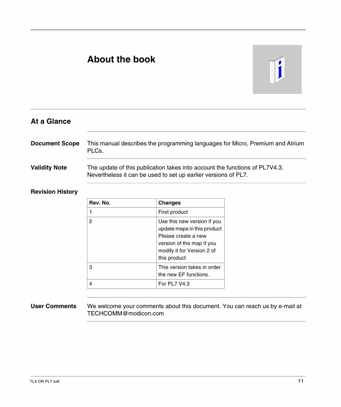
Document Scope This manual describes the programming languages for Micro, Premium and Atrium PLCs.
Validity Note The update of this publication takes into account the functions of PL7V4.3. Nevertheless it can be used to set up earlier versions of PL7.
Revision History
User Comments We welcome your comments about this document. You can reach us by e-mail at [email protected]
Rev. No. Changes
1 First product
2 Use this new version if you update maps in this product Please create a new version of the map if you modify it for Version 2 of this product
3 This version takes in order the new EF functions.
4 For PL7 V4.3
TLX DR PL7 xxE 11

About the book
12 TLX DR PL7 xxE
TLX DR PL7 xxE
1
Standard instructionsIntroduction
Contents of this section
This chapter describes the standard instructions for PL7 language.
What's in this Chapter?
This Chapter contains the following Sections:
Section Topic Page
1.1 Introduction to the PL7 instructions 14
1.2 Boolean instructions 15
1.3 Predefined function blocks 31
1.4 Numerical processing on integers 47
1.5 Program instructions 65
13
Standard instructions
1.1 Introduction to the PL7 instructions
PL7 Instructions
General All PL7 languages use the same instruction set.
Boolean instructions and function blocks are represented differently according to the language.
Example: loading instruction
Digital instructions (arithmetic, logic, task, etc.) have similar representations.
This document gives a detailed description of all the instructions; these have been put into two sets for the sake of simplicity: � the basic instructions (See Standard instructions, p. 13)� the advanced instructions (See Advanced instructions, p. 79)
Basic instructions
These comprise all the basic boolean instructions, the predefined function blocks, and the arithmetic and logic instructions on integers.
Advanced instructions
These comprise instructions which address advanced programming needs. These instructions are of two types:� PL7 language, these increase the possibilities for language processing using
specific functions (manipulation of character strings, time management, etc.),� tasks, these offer functions specific to the task to be processed, for example
functions for the communication task:� PRINT to send a character string type message to a terminal or printer, � SEND to send a message to an application,� PID PID regulating function.
Instruction Ladder language Instruction list Structured text
Loading LD :=
14 TLX DR PL7 xxE
Standard instructions
1.2 Boolean instructions
Introduction
Aim of this section
This section describes the PL7 language boolean instructions
What's in this Section?
This Section contains the following Maps:
Topic Page
Bit object instructions 16
Definition of the main boolean objects 17
Loading instructions 18
Assign instructions 20
AND Logic Instruction 22
OR Logic Instruction 25
Exclusive OR Instructions 28
TLX DR PL7 xxE 15
Standard instructions
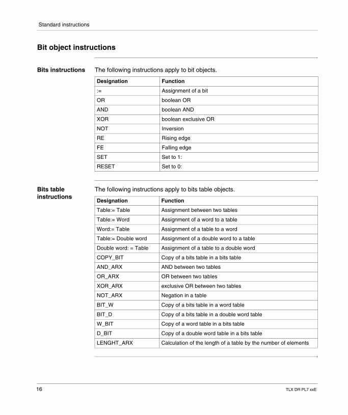
Bit object instructions
Bits instructions The following instructions apply to bit objects.
Bits table instructions
The following instructions apply to bits table objects.
Designation Function
:= Assignment of a bit
OR boolean OR
AND boolean AND
XOR boolean exclusive OR
NOT Inversion
RE Rising edge
FE Falling edge
SET Set to 1:
RESET Set to 0:
Designation Function
Table:= Table Assignment between two tables
Table:= Word Assignment of a word to a table
Word:= Table Assignment of a table to a word
Table:= Double word Assignment of a double word to a table
Double word: = Table Assignment of a table to a double word
COPY_BIT Copy of a bits table in a bits table
AND_ARX AND between two tables
OR_ARX OR between two tables
XOR_ARX exclusive OR between two tables
NOT_ARX Negation in a table
BIT_W Copy of a bits table in a word table
BIT_D Copy of a bits table in a double word table
W_BIT Copy of a word table in a bits table
D_BIT Copy of a double word table in a bits table
LENGHT_ARX Calculation of the length of a table by the number of elements
16 TLX DR PL7 xxE
Standard instructions
Definition of the main boolean objects
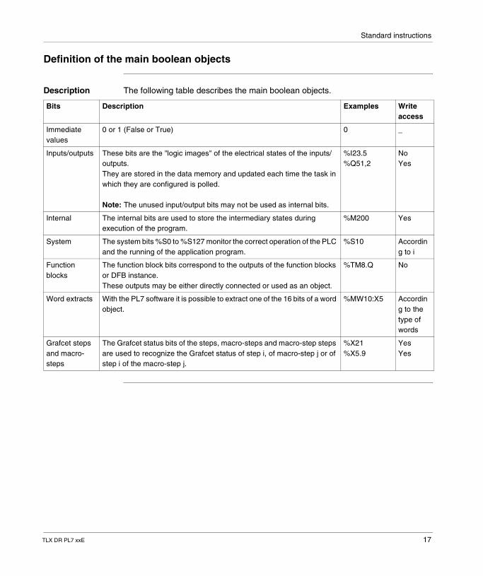
Description The following table describes the main boolean objects.
Bits Description Examples Write access
Immediate values
0 or 1 (False or True) 0 _
Inputs/outputs These bits are the "logic images" of the electrical states of the inputs/outputs. They are stored in the data memory and updated each time the task in which they are configured is polled.
Note: The unused input/output bits may not be used as internal bits.
%I23.5%Q51,2
NoYes
Internal The internal bits are used to store the intermediary states during execution of the program.
%M200 Yes
System The system bits %S0 to %S127 monitor the correct operation of the PLC and the running of the application program.
%S10 According to i
Function blocks
The function block bits correspond to the outputs of the function blocks or DFB instance. These outputs may be either directly connected or used as an object.
%TM8.Q No
Word extracts With the PL7 software it is possible to extract one of the 16 bits of a word object.
%MW10:X5 According to the type of words
Grafcet steps and macro-steps
The Grafcet status bits of the steps, macro-steps and macro-step steps are used to recognize the Grafcet status of step i, of macro-step j or of step i of the macro-step j.
%X21%X5.9
YesYes
TLX DR PL7 xxE 17
Standard instructions
Loading instructions
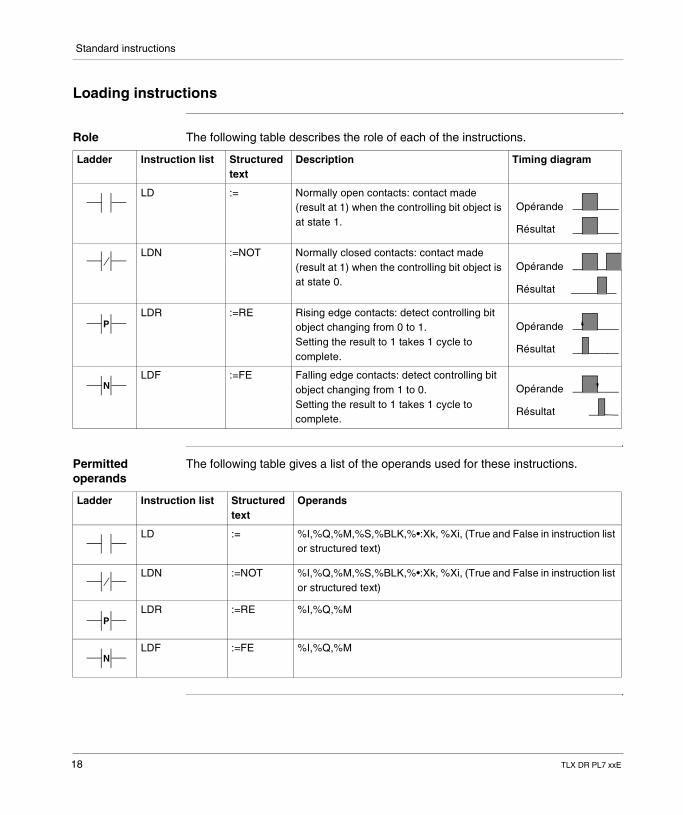
Role The following table describes the role of each of the instructions.
Permitted operands
The following table gives a list of the operands used for these instructions.
Ladder Instruction list Structured text
Description Timing diagram
LD := Normally open contacts: contact made (result at 1) when the controlling bit object is at state 1.
LDN :=NOT Normally closed contacts: contact made (result at 1) when the controlling bit object is at state 0.
LDR :=RE Rising edge contacts: detect controlling bit object changing from 0 to 1.Setting the result to 1 takes 1 cycle to complete.
LDF :=FE Falling edge contacts: detect controlling bit object changing from 1 to 0.Setting the result to 1 takes 1 cycle to complete.
Opérande
Résultat
Opérande
Résultat
P Opérande
Résultat
N Opérande
Résultat
Ladder Instruction list Structured text
Operands
LD := %I,%Q,%M,%S,%BLK,%•:Xk, %Xi, (True and False in instruction list or structured text)
LDN :=NOT %I,%Q,%M,%S,%BLK,%•:Xk, %Xi, (True and False in instruction list or structured text)
LDR :=RE %I,%Q,%M
LDF :=FE %I,%Q,%M
P
N
18 TLX DR PL7 xxE
Standard instructions
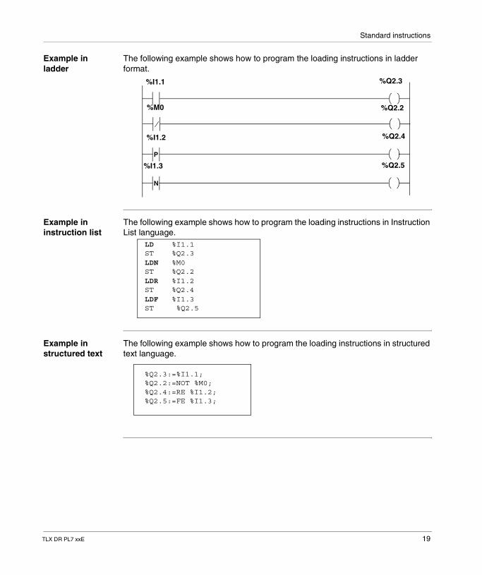
Example in ladder
The following example shows how to program the loading instructions in ladder format.
Example in instruction list
The following example shows how to program the loading instructions in Instruction List language.
Example in structured text
The following example shows how to program the loading instructions in structured text language.
P
N
%I1.1 %Q2.3
%M0
%I1.2 %Q2.4
%I1.3 %Q2.5
%Q2.2
LD %I1.1ST %Q2.3LDN %M0ST %Q2.2LDR %I1.2ST %Q2.4LDF %I1.3ST %Q2.5
%Q2.3:=%I1.1;%Q2.2:=NOT %M0;%Q2.4:=RE %I1.2;%Q2.5:=FE %I1.3;
TLX DR PL7 xxE 19
Standard instructions
Assign instructions
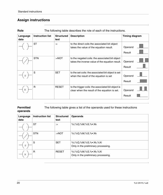
Role The following table describes the role of each of the instructions.
Permitted operands
The following table gives a list of the operands used for these instructions
Language data
Instruction list Structured text
Description Timing diagram
ST := to the direct coils the associated bit object takes the value of the equation result.
STN :=NOT to the negated coils: the associated bit object takes the inverse value of the equation result.
S SET to the set coils: the associated bit object is set when the result of the equation is set
R RESET to the trigger coils: the associated bit object is clear when the result of the equation is set.
Operand
Result
Operand
Result
S Operand
Result
R Operand
Result
Language data
Instruction list Structured text
Operands
ST := %I,%Q,%M,%S,%•:Xk
STN :=NOT %I,%Q,%M,%S,%•:Xk
S SET %I,%Q,%M,%S,%•:Xk,%XiOnly in the preliminary processing.
R RESET %I,%Q,%M,%S,%•:Xk,%XiOnly in the preliminary processing.
S
R
20 TLX DR PL7 xxE
Standard instructions
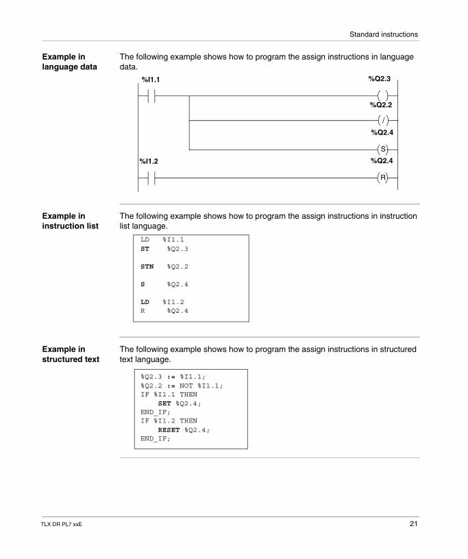
Example in language data
The following example shows how to program the assign instructions in language data.
Example in instruction list
The following example shows how to program the assign instructions in instruction list language.
Example in structured text
The following example shows how to program the assign instructions in structured text language.
%I1.1 %Q2.3
%Q2.4
%I1.2 %Q2.4
%Q2.2
S
R
LD %I1.1ST %Q2.3
STN %Q2.2
S %Q2.4
LD %I1.2R %Q2.4
%Q2.3 := %I1.1;%Q2.2 := NOT %I1.1;IF %I1.1 THEN SET %Q2.4;END_IF;IF %I1.2 THEN RESET %Q2.4;END_IF;
TLX DR PL7 xxE 21
Standard instructions
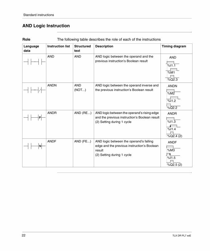
AND Logic Instruction
Role The following table describes the role of each of the instructions
Language data
Instruction list Structured text
Description Timing diagram
AND AND AND logic between the operand and the previous instruction’s Boolean result
ANDN AND (NOT...)
AND logic between the operand inverse and the previous instruction’s Boolean result
ANDR AND (RE...) AND logic between the operand’s rising edge and the previous instruction’s Boolean result(2) Setting during 1 cycle
ANDF AND (FE...) AND logic between the operand’s falling edge and the previous instruction’s Boolean result(2) Setting during 1 cycle
%I1.1
AND
%M1
%Q2.3
%M2
%I1.2
%Q2.2
ANDN
PANDR
%I1.3
%I1.4
%Q2.4 (2)
NANDF
%M3
%I1.5
%Q2.5 (2)
22 TLX DR PL7 xxE
Standard instructions
Permitted operands
The following table gives a list of the operands used for these instructions
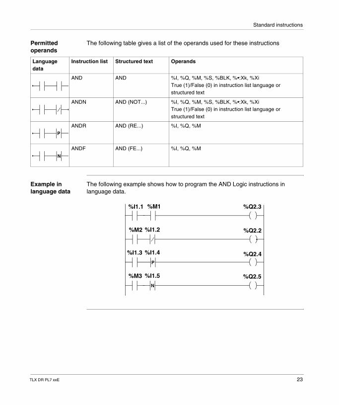
Example in language data
The following example shows how to program the AND Logic instructions in language data.
Language data
Instruction list Structured text Operands
AND AND %I, %Q, %M, %S, %BLK, %•:Xk, %XiTrue (1)/False (0) in instruction list language or structured text
ANDN AND (NOT...) %I, %Q, %M, %S, %BLK, %•:Xk, %XiTrue (1)/False (0) in instruction list language or structured text
ANDR AND (RE...) %I, %Q, %M
ANDF AND (FE...) %I, %Q, %M
P
N
P
N
%I1.1 %M1
%M2
%M3
%I1.2
%I1.3 %I1.4
%I1.5
%Q2.3
%Q2.2
%Q2.4
%Q2.5
TLX DR PL7 xxE 23
Standard instructions
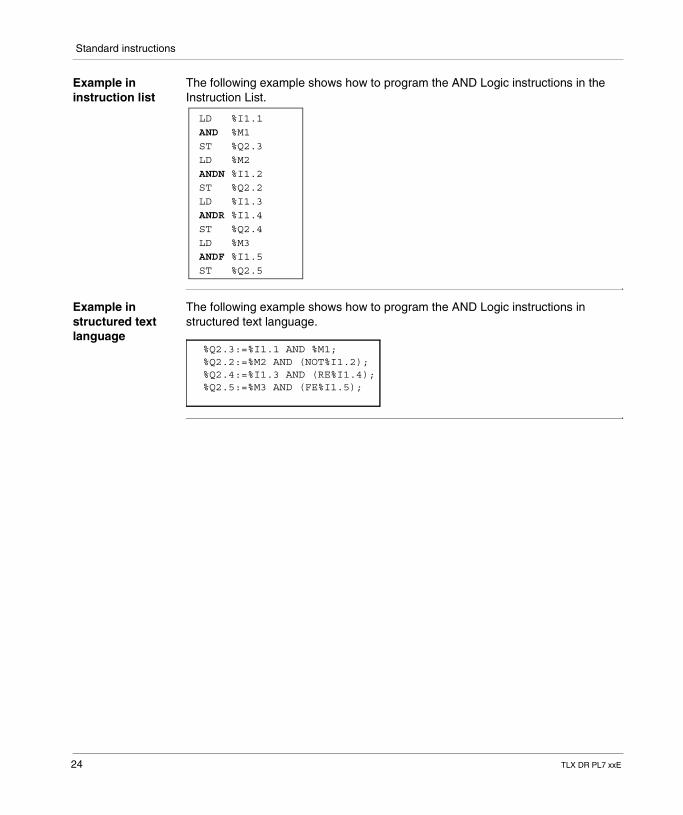
Example in instruction list
The following example shows how to program the AND Logic instructions in the Instruction List.
Example in structured text language
The following example shows how to program the AND Logic instructions in structured text language.
LD %I1.1AND %M1ST %Q2.3LD %M2ANDN %I1.2ST %Q2.2LD %I1.3ANDR %I1.4ST %Q2.4LD %M3ANDF %I1.5ST %Q2.5
%Q2.3:=%I1.1 AND %M1;%Q2.2:=%M2 AND (NOT%I1.2);%Q2.4:=%I1.3 AND (RE%I1.4);%Q2.5:=%M3 AND (FE%I1.5);
24 TLX DR PL7 xxE
Standard instructions
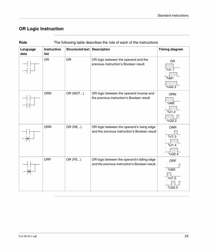
OR Logic Instruction
Role The following table describes the role of each of the instructions
Language data
Instruction list
Structured text Description Timing diagram
OR OR OR logic between the operand and the previous instruction’s Boolean result
ORN OR (NOT...) OR logic between the operand inverse and the previous instruction’s Boolean result
ORR OR (RE...) OR logic between the operand’s rising edge and the previous instruction’s Boolean result
ORF OR (FE...) OR logic between the operand’s falling edge and the previous instruction’s Boolean result.
OR
%I1.1
%M1
%Q2.3
ORN
%M2
%I1.2
%Q2.2
P
ORR
%I1.3
%I1.4
%Q2.4
N
ORF
%M3
%I1.5
%Q2.5
TLX DR PL7 xxE 25
Standard instructions
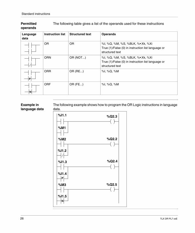
Permitted operands
The following table gives a list of the operands used for these instructions
Example in language data
The following example shows how to program the OR Logic instructions in language data.
Language data
Instruction list Structured text Operands
OR OR %I, %Q, %M, %S, %BLK, %•:Xk, %XiTrue (1)/False (0) in instruction list language or structured text
ORN OR (NOT...) %I, %Q, %M, %S, %BLK, %•:Xk, %XiTrue (1)/False (0) in instruction list language or structured text
ORR OR (RE...) %I, %Q, %M
ORF OR (FE...) %I, %Q, %M
P
N
P
N
%I1.1
%M1
%M2
%I1.2
%I1.3
%I1.4
%M3
%I1.5
%Q2.5
%Q2.4
%Q2.2
%Q2.3
26 TLX DR PL7 xxE
Standard instructions
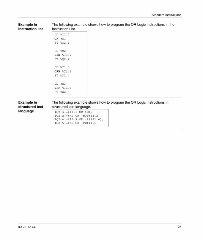
Example in instruction list
The following example shows how to program the OR Logic instructions in the Instruction List.
Example in structured text language
The following example shows how to program the OR Logic instructions in structured text language.
LD %I1.1OR %M1ST %Q2.3
LD %M2ORN %I1.2ST %Q2.2
LD %I1.3ORR %I1.4ST %Q2.4
LD %M3ORF %I1.5ST %Q2.5
%Q2.3:=%I1.1 OR %M1;%Q2.2:=%M2 OR (NOT%I1.2);%Q2.4:=%I1.3 OR (RE%I1.4);%Q2.5:=%M3 OR (FE%I1.5);
TLX DR PL7 xxE 27
Standard instructions
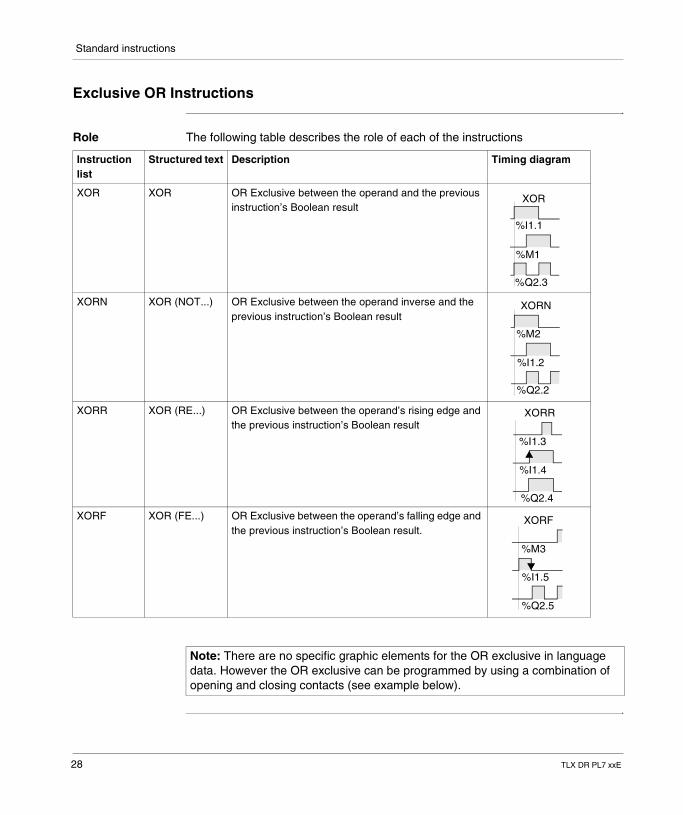
Exclusive OR Instructions
Role The following table describes the role of each of the instructions
Instruction list
Structured text Description Timing diagram
XOR XOR OR Exclusive between the operand and the previous instruction’s Boolean result
XORN XOR (NOT...) OR Exclusive between the operand inverse and the previous instruction’s Boolean result
XORR XOR (RE...) OR Exclusive between the operand’s rising edge and the previous instruction’s Boolean result
XORF XOR (FE...) OR Exclusive between the operand’s falling edge and the previous instruction’s Boolean result.
XOR
%I1.1
%M1
%Q2.3
XORN
%M2
%I1.2
%Q2.2
XORR
%I1.3
%I1.4
%Q2.4
XORF
%M3
%I1.5
%Q2.5
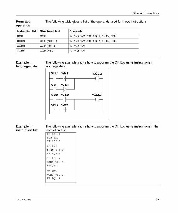
Note: There are no specific graphic elements for the OR exclusive in language data. However the OR exclusive can be programmed by using a combination of opening and closing contacts (see example below).
28 TLX DR PL7 xxE
Standard instructions
Permitted operands
The following table gives a list of the operands used for these instructions
Example in language data
The following example shows how to program the OR Exclusive instructions in language data.
Example in instruction list
The following example shows how to program the OR Exclusive instructions in the Instruction List:
Instruction list Structured text Operands
XOR XOR %I, %Q, %M, %S, %BLK, %•:Xk, %Xi
XORN XOR (NOT...) %I, %Q, %M, %S, %BLK, %•:Xk, %Xi
XORR XOR (RE...) %I, %Q, %M
XORF XOR (FE...) %I, %Q, %M
%I1.1 %M1
%M1 %I1.1
%M2 %I1.2
%I1.2 %M2
%Q2.3
%Q2.2
LD %I1.1XOR %M1ST %Q2.3
LD %M2XORN %I1.2ST %Q2.2
LD %I1.3XORR %I1.4ST%Q2.4
LD %M3XORF %I1.5ST %Q2.5
TLX DR PL7 xxE 29
Standard instructions
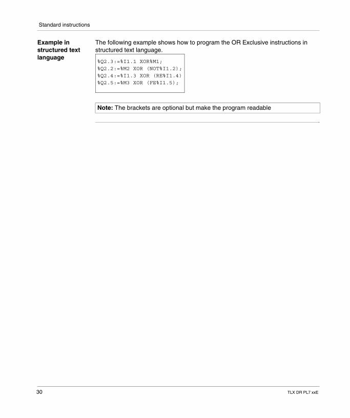
Example in structured text language
The following example shows how to program the OR Exclusive instructions in structured text language.
Note: The brackets are optional but make the program readable
%Q2.3:=%I1.1 XOR%M1;%Q2.2:=%M2 XOR (NOT%I1.2);%Q2.4:=%I1.3 XOR (RE%I1.4) %Q2.5:=%M3 XOR (FE%I1.5);
30 TLX DR PL7 xxE
Standard instructions
1.3 Predefined function blocks
Introduction
Aim of this sub-section
This sub-section describes PL7 language predefined function Blocks
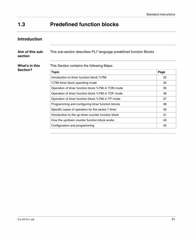
What's in this Section?
This Section contains the following Maps:
Topic Page
Introduction to timer function block %TMi 32
%TMi timer block operating mode 34
Operation of timer function block %TMi in TON mode 35
Operation of timer function block %TMi in TOF mode 36
Operation of timer function block %TMi in TP mode 37
Programming and configuring timer function blocks 38
Specific cases of operation for the series 7 timer 40
Introduction to the up-down counter function block 41
How the up/down counter function block works 43
Configuration and programming 45
TLX DR PL7 xxE 31
Standard instructions
Introduction to timer function block %TMi
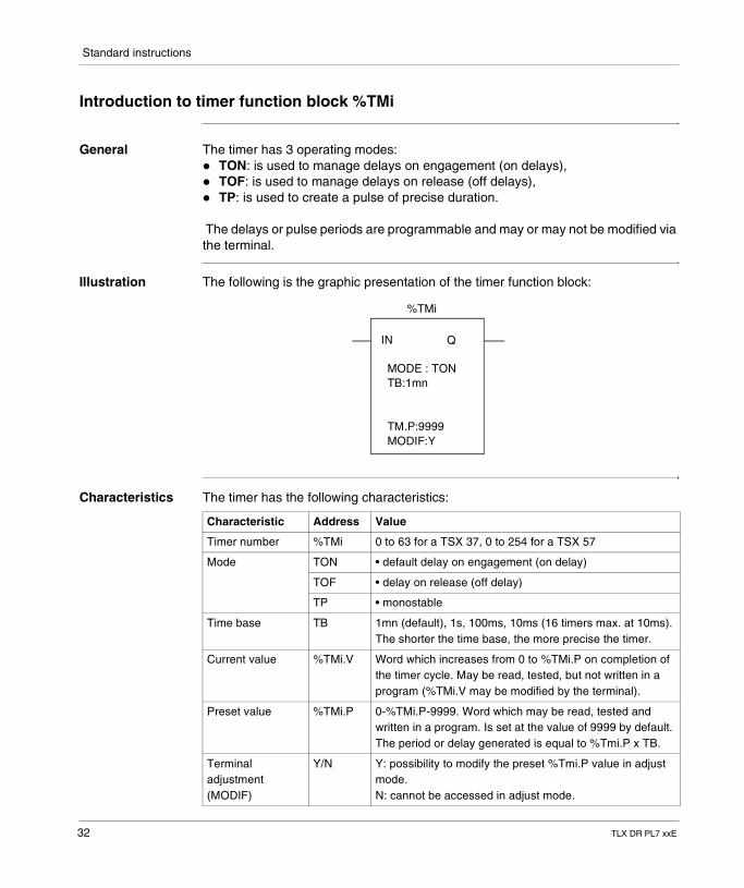
General The timer has 3 operating modes:� TON: is used to manage delays on engagement (on delays),� TOF: is used to manage delays on release (off delays),� TP: is used to create a pulse of precise duration.
The delays or pulse periods are programmable and may or may not be modified via the terminal.
Illustration The following is the graphic presentation of the timer function block:
Characteristics The timer has the following characteristics:
%TMi
IN Q
MODE : TONTB:1mn
TM.P:9999MODIF:Y
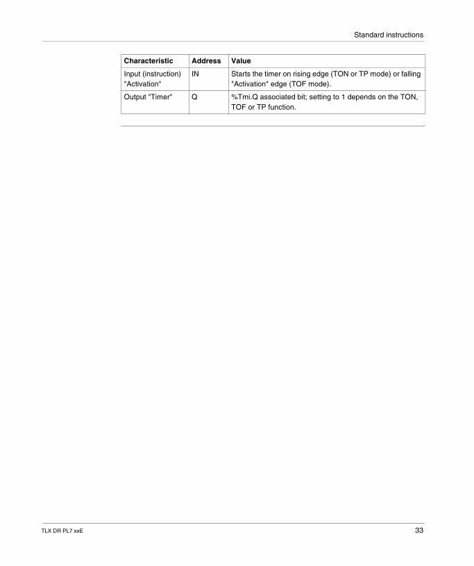
Characteristic Address Value
Timer number %TMi 0 to 63 for a TSX 37, 0 to 254 for a TSX 57
Mode TON • default delay on engagement (on delay)
TOF • delay on release (off delay)
TP • monostable
Time base TB 1mn (default), 1s, 100ms, 10ms (16 timers max. at 10ms). The shorter the time base, the more precise the timer.
Current value %TMi.V Word which increases from 0 to %TMi.P on completion of the timer cycle. May be read, tested, but not written in a program (%TMi.V may be modified by the terminal).
Preset value %TMi.P 0-%TMi.P-9999. Word which may be read, tested and written in a program. Is set at the value of 9999 by default. The period or delay generated is equal to %Tmi.P x TB.
Terminal adjustment (MODIF)
Y/N Y: possibility to modify the preset %Tmi.P value in adjust mode.N: cannot be accessed in adjust mode.
32 TLX DR PL7 xxE
Standard instructions
Input (instruction) "Activation"
IN Starts the timer on rising edge (TON or TP mode) or falling "Activation" edge (TOF mode).
Output "Timer" Q %Tmi.Q associated bit; setting to 1 depends on the TON, TOF or TP function.
Characteristic Address Value
TLX DR PL7 xxE 33
Standard instructions
%TMi timer block operating mode
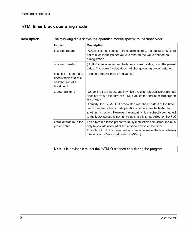
Description The following table shows the operating modes specific to the timer block.
Impact... Description
of a cold restart (%S0=1), causes the current value to set to 0, the output %TMi.Q to set to 0 while the preset value is reset to the value defined on configuration.
of a warm restart (%S1=1) has no effect on the timer’s current value, or on the preset value. The current value does not change during power outage.
of a shift to stop mode, deactivation of a task or execution of a breakpoint
does not freeze the current value.
a program jump Not polling the instructions in which the timer block is programmed does not freeze the current %TMi.V value; this continues to increase to %TMi.P.Similarly, the %TMi.Q bit associated with the Q output of the timer block maintains its normal operation and can thus be tested by another instruction. However the output, which is directly connected to the block output, is not activated since it is not polled by the PLC
of the alteration to the preset value
The alteration to the preset value by instruction or in adjust mode is only taken into account at the next activation of the timer.The alteration to the preset value in the variables editor is only taken into account after a cold restart (%S0=1).
Note: it is advisable to test the %TMi.Q bit once only during the program.
34 TLX DR PL7 xxE
Standard instructions
Operation of timer function block %TMi in TON mode
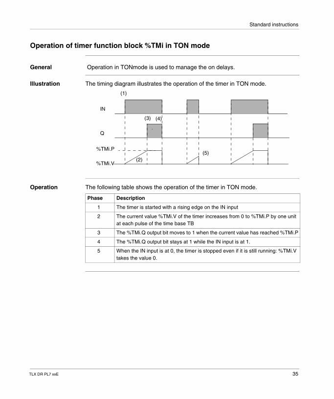
General Operation in TONmode is used to manage the on delays.
Illustration The timing diagram illustrates the operation of the timer in TON mode.
Operation The following table shows the operation of the timer in TON mode.
IN
Q
%TMi.P
%TMi.V
(1)
(2)
(3) (4)
(5)
Phase Description
1 The timer is started with a rising edge on the IN input
2 The current value %TMi.V of the timer increases from 0 to %TMi.P by one unit at each pulse of the time base TB
3 The %TMi.Q output bit moves to 1 when the current value has reached %TMi.P
4 The %TMi.Q output bit stays at 1 while the IN input is at 1.
5 When the IN input is at 0, the timer is stopped even if it is still running: %TMi.V takes the value 0.
TLX DR PL7 xxE 35
Standard instructions
Operation of timer function block %TMi in TOF mode
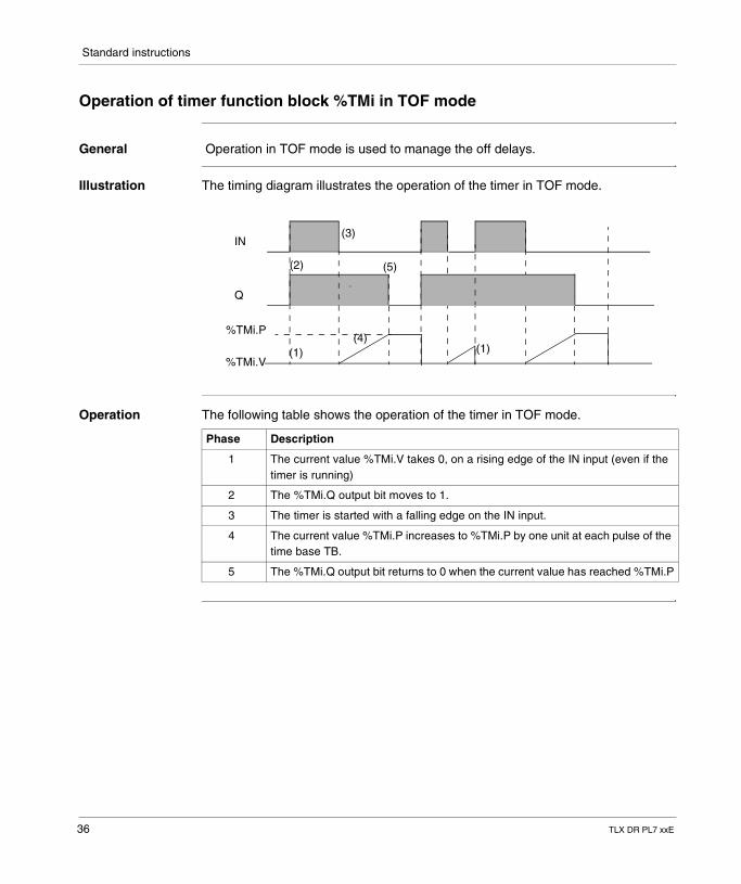
General Operation in TOF mode is used to manage the off delays.
Illustration The timing diagram illustrates the operation of the timer in TOF mode.
Operation The following table shows the operation of the timer in TOF mode.
IN
Q
%TMi.P
%TMi.V(1)
(3)
(4)
(2) (5)
(1)
Phase Description
1 The current value %TMi.V takes 0, on a rising edge of the IN input (even if the timer is running)
2 The %TMi.Q output bit moves to 1.
3 The timer is started with a falling edge on the IN input.
4 The current value %TMi.P increases to %TMi.P by one unit at each pulse of the time base TB.
5 The %TMi.Q output bit returns to 0 when the current value has reached %TMi.P
36 TLX DR PL7 xxE
Standard instructions
Operation of timer function block %TMi in TP mode
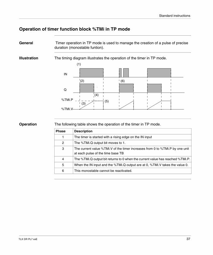
General Timer operation in TP mode is used to manage the creation of a pulse of precise duration (monostable funtion).
Illustration The timing diagram illustrates the operation of the timer in TP mode.
Operation The following table shows the operation of the timer in TP mode.
IN
Q
%TMi.P
%TMi.V
(1)
(2)
(3)
(4)
(6)
(5)
Phase Description
1 The timer is started with a rising edge on the IN input
2 The %TMi.Q output bit moves to 1.
3 The current value %TMi.V of the timer increases from 0 to %TMi.P by one unit at each pulse of the time base TB
4 The %TMi.Q output bit returns to 0 when the current value has reached %TMi.P.
5 When the IN input and the %TMi.Q output are at 0, %TMi.V takes the value 0.
6 This monostable cannot be reactivated.
TLX DR PL7 xxE 37
Standard instructions
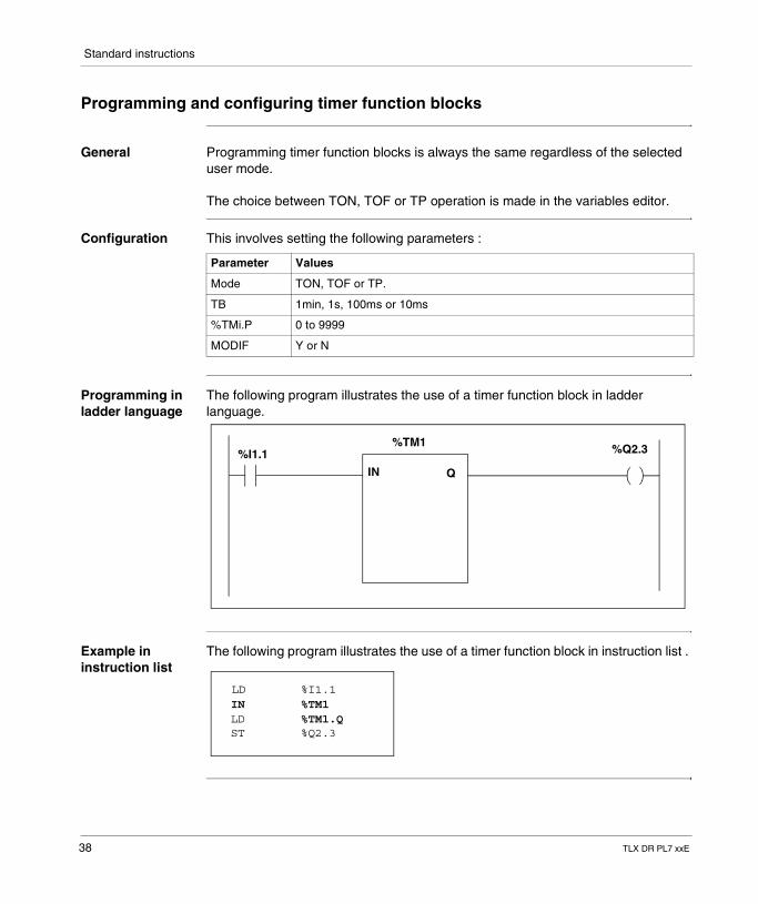
Programming and configuring timer function blocks
General Programming timer function blocks is always the same regardless of the selected user mode.
The choice between TON, TOF or TP operation is made in the variables editor.
Configuration This involves setting the following parameters :
Programming in ladder language
The following program illustrates the use of a timer function block in ladder language.
Example in instruction list
The following program illustrates the use of a timer function block in instruction list .
Parameter Values
Mode TON, TOF or TP.
TB 1min, 1s, 100ms or 10ms
%TMi.P 0 to 9999
MODIF Y or N
%TM1%I1.1 %Q2.3
IN Q
LD %I1.1IN %TM1LD %TM1.QST %Q2.3
38 TLX DR PL7 xxE
Standard instructions
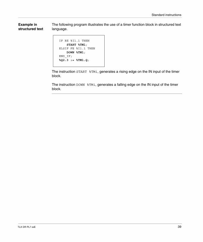
Example in structured text
The following program illustrates the use of a timer function block in structured text language.
The instruction START %TMi, generates a rising edge on the IN input of the timer block.
The instruction DOWN %TMi, generates a falling edge on the IN input of the timer block.
IF RE %I1.1 THEN START %TM1;ELSIF FE %I1.1 THEN DOWN %TM1;END_IF;%Q2.3 := %TM1.Q;
TLX DR PL7 xxE 39
Standard instructions
Specific cases of operation for the series 7 timer
Specific cases � Incidence of a "cold restart": (%S0 = 1) loads the preset value (defined by the variables editor) in the current value and sets the output %Ti.D at 0, as the preset value, which may have been altered by the terminal, has been lost.
� Incidence of a "warm restart": there is no incidence of (%S1=1) on the current value of the timer.
� Incidence of a switch to stop mode: the switch of the PLC into stop mode does not freeze the current value. The same applies when the current task is deactivated or on execution of a breakpoint.
� Incidence of a program jump: not polling the network in which the timer block is programmed does not freeze the current value %Ti.V which continues to decrease to 0. Similarly, the %Ti.D and %Ti.R bits associated with the D and R outputs maintain their normal operation and can thus be tested on another network. However the spools which are directly connected to the block outputs are not activated since they are not polled by the PLC.
� Test of %Ti.D and %Ti.R bits: these bits can change state during the cycle.
40 TLX DR PL7 xxE
Standard instructions
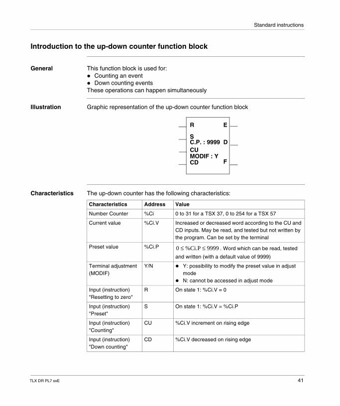
Introduction to the up-down counter function block
General This function block is used for:� Counting an event� Down counting eventsThese operations can happen simultaneously
Illustration Graphic representation of the up-down counter function block
Characteristics The up-down counter has the following characteristics:
R
S
CU
CDMODIF : Y
C.P. : 9999
E
D
F
Characteristics Address Value
Number Counter %Ci 0 to 31 for a TSX 37, 0 to 254 for a TSX 57
Current value %Ci.V Increased or decreased word according to the CU and CD inputs. May be read, and tested but not written by the program. Can be set by the terminal
Preset value %Ci.P . Word which can be read, tested
and written (with a default value of 9999)
Terminal adjustment (MODIF)
Y/N � Y: possibility to modify the preset value in adjust mode
� N: cannot be accessed in adjust mode
Input (instruction) "Resetting to zero"
R On state 1: %Ci.V = 0
Input (instruction) "Preset"
S On state 1: %Ci.V = %Ci.P
Input (instruction) "Counting"
CU %Ci.V increment on rising edge
Input (instruction) "Down counting"
CD %Ci.V decreased on rising edge
0 %Ci.P 9999≤ ≤
TLX DR PL7 xxE 41
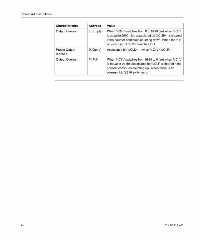
Standard instructions
Output Overrun E (Empty) When %Ci.V switches from 0 to 9999 (set when %Ci.V is equal to 9999), the associated bit %Ci.E=1 is cleared if the counter continues counting down. When there is an overrun, bit %S18 switches to 1
Preset Output reached
D (Done) Associated bit %Ci.D=1, when %Ci.V=%Ci.P.
Output Overrun F (Full) When %Ci.V switches from 9999 to 0 (set when %Ci.V is equal to 0), the associated bit %Ci.F is cleared if the counter continues counting up. When there is an overrun, bit %S18 switches to 1
Characteristics Address Value
42 TLX DR PL7 xxE
Standard instructions
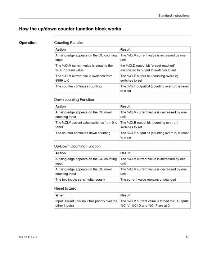
How the up/down counter function block works
Operation Counting Function
Down counting Function
Up/Down Counting Function
Reset to zero
Action Result
A rising edge appears on the CU counting input
The %Ci.V current value is increased by one unit
The %Ci.V current value is equal to the %Ci.P preset value
the %Ci.D output bit "preset reached" associated to output D switches to set
The %Ci.V current value switches from 9999 to 0
The %Ci.F output bit (counting overrun) switches to set
The counter continues counting The %Ci.F output bit (counting overrun) is reset to clear
Action Result
A rising edge appears on the CU down counting input
The %Ci.V current value is decreased by one unit
The %Ci.V current value switches from 0 to 9999
The %Ci.E output bit (counting overrun) switches to set
The counter continues down counting The %Ci.E output bit (counting overrun) is reset to clear
Action Result
A rising edge appears on the CU counting input
The %Ci.V current value is increased by one unit
A rising edge appears on the CU down counting input
The %Ci.V current value is decreased by one unit
The two inputs set simultaneously The current value remains unchanged
When Result
Input R is set (this input has priority over the other inputs)
The %Ci.V current value is forced to 0. Outputs %Ci.V, %CI.D and %CI.F are at 0
TLX DR PL7 xxE 43
Standard instructions
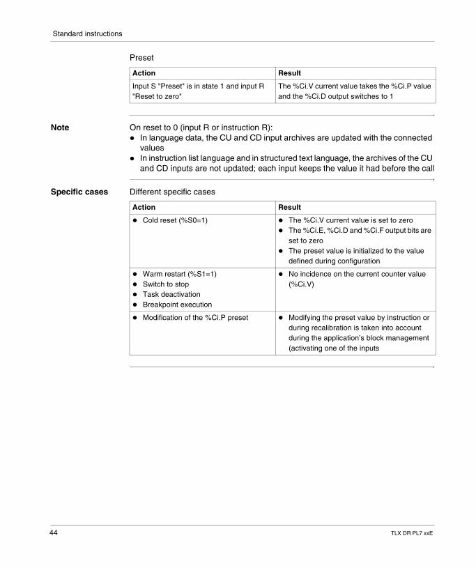
Preset
Note On reset to 0 (input R or instruction R):� In language data, the CU and CD input archives are updated with the connected
values� In instruction list language and in structured text language, the archives of the CU
and CD inputs are not updated; each input keeps the value it had before the call
Specific cases Different specific cases
Action Result
Input S "Preset" is in state 1 and input R "Reset to zero"
The %Ci.V current value takes the %Ci.P value and the %Ci.D output switches to 1
Action Result
� Cold reset (%S0=1) � The %Ci.V current value is set to zero� The %Ci.E, %Ci.D and %Ci.F output bits are
set to zero� The preset value is initialized to the value
defined during configuration
� Warm restart (%S1=1)� Switch to stop� Task deactivation� Breakpoint execution
� No incidence on the current counter value (%Ci.V)
� Modification of the %Ci.P preset � Modifying the preset value by instruction or during recalibration is taken into account during the application’s block management (activating one of the inputs
44 TLX DR PL7 xxE
Standard instructions
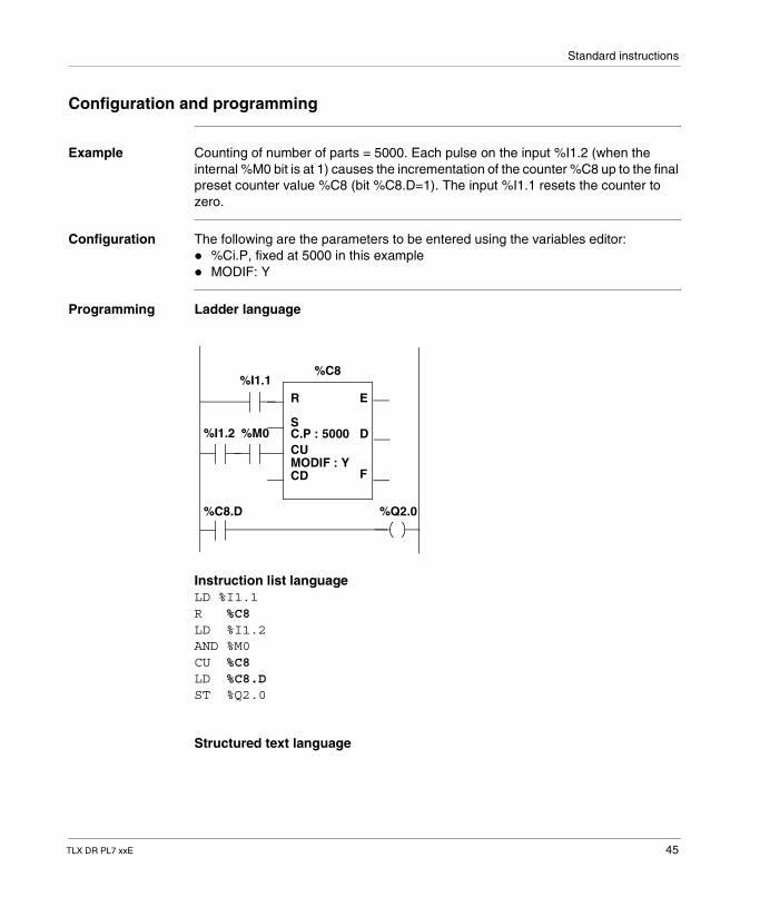
Configuration and programming
Example Counting of number of parts = 5000. Each pulse on the input %I1.2 (when the internal %M0 bit is at 1) causes the incrementation of the counter %C8 up to the final preset counter value %C8 (bit %C8.D=1). The input %I1.1 resets the counter to zero.
Configuration The following are the parameters to be entered using the variables editor:� %Ci.P, fixed at 5000 in this example� MODIF: Y
Programming Ladder language
Instruction list languageLD %I1.1R %C8LD %I1.2AND %M0CU %C8LD %C8.DST %Q2.0
Structured text language
R
S
CU
CDMODIF : Y
C.P : 5000
E
D
F
%C8%I1.1
%M0%I1.2
%C8.D %Q2.0
TLX DR PL7 xxE 45
Standard instructions
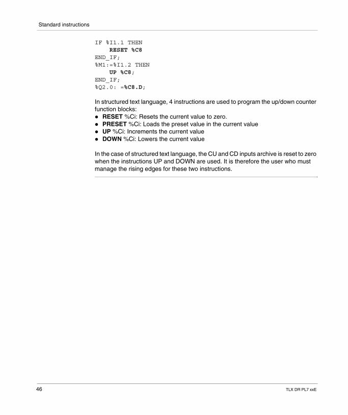
IF %I1.1 THEN RESET %C8END_IF;%M1:=%I1.2 THEN UP %C8;END_IF;%Q2.0: =%C8.D;
In structured text language, 4 instructions are used to program the up/down counter function blocks:� RESET %Ci: Resets the current value to zero.� PRESET %Ci: Loads the preset value in the current value� UP %Ci: Increments the current value� DOWN %Ci: Lowers the current value
In the case of structured text language, the CU and CD inputs archive is reset to zero when the instructions UP and DOWN are used. It is therefore the user who must manage the rising edges for these two instructions.
46 TLX DR PL7 xxE
Standard instructions
1.4 Numerical processing on integers
Introduction
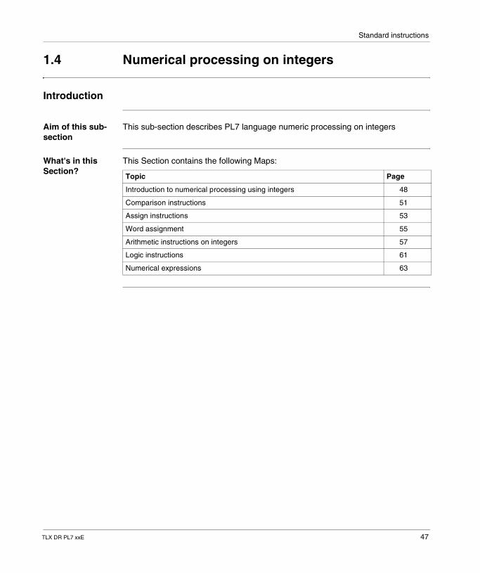
Aim of this sub-section
This sub-section describes PL7 language numeric processing on integers
What's in this Section?
This Section contains the following Maps:
Topic Page
Introduction to numerical processing using integers 48
Comparison instructions 51
Assign instructions 53
Word assignment 55
Arithmetic instructions on integers 57
Logic instructions 61
Numerical expressions 63
TLX DR PL7 xxE 47
Standard instructions
Introduction to numerical processing using integers
General The numerical instructions described in this chapter are for the following objects:� bit tables� words� double wordsInstructions for other object types are described in the "Advanced instructions (See Advanced instructions, p. 79)" section.
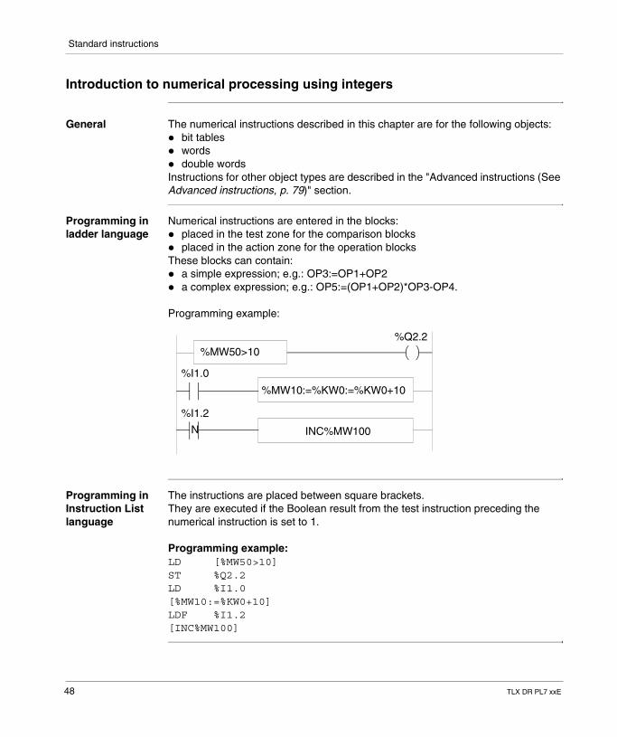
Programming in ladder language
Numerical instructions are entered in the blocks:� placed in the test zone for the comparison blocks� placed in the action zone for the operation blocksThese blocks can contain:� a simple expression; e.g.: OP3:=OP1+OP2� a complex expression; e.g.: OP5:=(OP1+OP2)*OP3-OP4.
Programming example:
Programming in Instruction List language
The instructions are placed between square brackets.They are executed if the Boolean result from the test instruction preceding the numerical instruction is set to 1.
Programming example:LD [%MW50>10]ST %Q2.2LD %I1.0[%MW10:=%KW0+10]LDF %I1.2[INC%MW100]
N
%MW50>10
%MW10:=%KW0:=%KW0+10
INC%MW100
%Q2.2
%I1.0
%I1.2
48 TLX DR PL7 xxE
Standard instructions
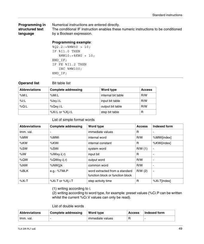
Programming in structured text language
Numerical instructions are entered directly.The conditional IF instruction enables these numeric instructions to be conditioned by a Boolean expression.
Programming example:%Q2.2:=%MW50 > 10;IF %I1.0 THEN %MW10:=%KW0 + 10;END_IF;IF FE %I1.2 THEN INC %MW100;END_IF;
Operand list Bit table list
List of simple format words
(1) writing according to i. (2) writing according to word type, for example: preset values (%Ci.P can be written whilst the current %Ci.V values can only be read).
List of double words
Abbreviations Complete addressing Word type Access
%M:L %Mi:L internal bit table R/W
%I:L %Ixy.i:L input bit table R/W
%Q:L %Qxy.i:L output bit table R/W
%Xi:L or %Xj.i:L step bit table R
Abbreviations Complete addressing Word type Access Indexed form
Imm. val. - immediate values R -
%MW %MWi internal word R/W %MWi[index]
%KW %KWi internal constant R %KWi[index]
%SW %SWi system word R/W (1) -
%IW %IWxy.i(.r) input bit R -
%QW %QWxy.i(.r) output word R/W -
%NW %NW{j}k common word R/W -
%BLK e.g.: %TMi.P word extracted from a standard function block or function block
R/W (2) -
%Xi.T %Xi.T or %Xj.i.T step activity time R %Xi.T[index]
Abbreviations Complete addressing Word type Access Indexed form
Imm. val. - immediate values R -
TLX DR PL7 xxE 49
Standard instructions
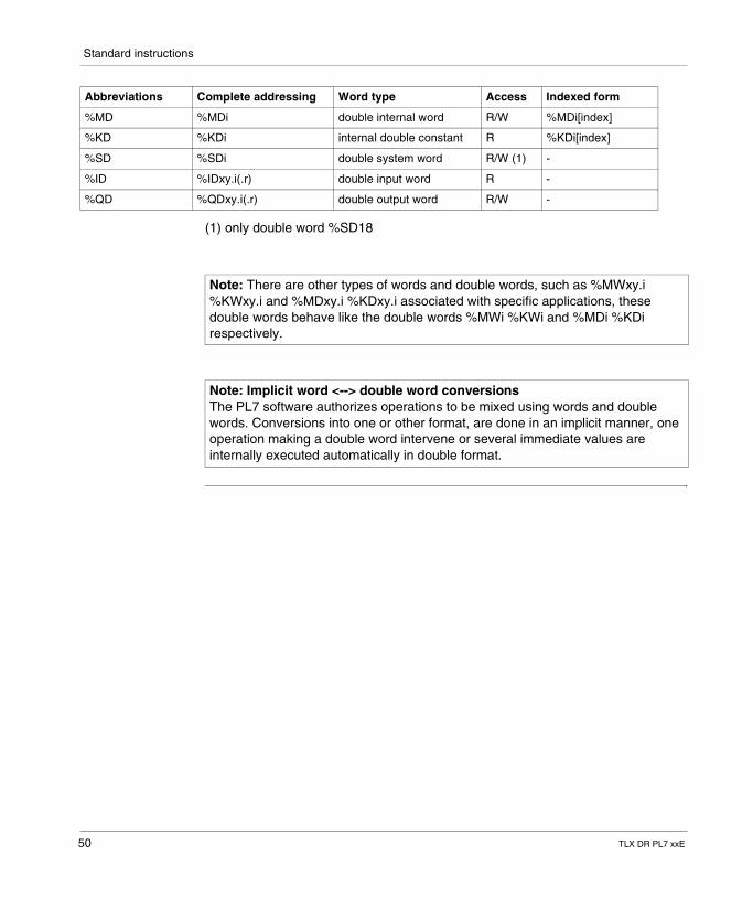
(1) only double word %SD18
%MD %MDi double internal word R/W %MDi[index]
%KD %KDi internal double constant R %KDi[index]
%SD %SDi double system word R/W (1) -
%ID %IDxy.i(.r) double input word R -
%QD %QDxy.i(.r) double output word R/W -
Abbreviations Complete addressing Word type Access Indexed form
Note: There are other types of words and double words, such as %MWxy.i %KWxy.i and %MDxy.i %KDxy.i associated with specific applications, these double words behave like the double words %MWi %KWi and %MDi %KDi respectively.
Note: Implicit word <--> double word conversions The PL7 software authorizes operations to be mixed using words and double words. Conversions into one or other format, are done in an implicit manner, one operation making a double word intervene or several immediate values are internally executed automatically in double format.
50 TLX DR PL7 xxE
Standard instructions
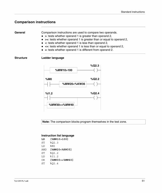
Comparison instructions
General Comparison instructions are used to compare two operands.� >: tests whether operand 1 is greater than operand 2,� >=: tests whether operand 1 is greater than or equal to operand 2,� <: tests whether operand 1 is less than operand 2,� <=: tests whether operand 1 is less than or equal to operand 2,� =: tests whether operand 1 is different from operand 2.
Structure Ladder language
Instruction list languageLD [%MW10>100]ST %Q2.3LD %M0AND [%MW20<%KW35]ST %Q2.2LD %I1.2OR [%MW30>=%MW40]ST %Q2.4
Note: The comparison blocks program themselves in the test zone.
%MW20<%KW35
%MW30>=%MW40
%M0
%I1.2
%MW10>100
%Q2.3
%Q2.2
%Q2.4
TLX DR PL7 xxE 51
Standard instructions
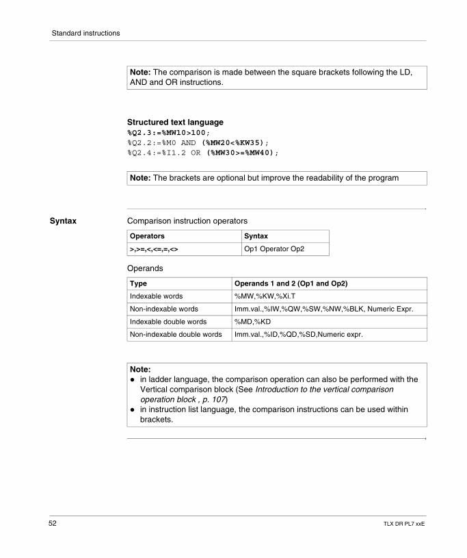
Structured text language%Q2.3:=%MW10>100;%Q2.2:=%M0 AND (%MW20<%KW35);%Q2.4:=%I1.2 OR (%MW30>=%MW40);
Syntax Comparison instruction operators
Operands
Note: The comparison is made between the square brackets following the LD, AND and OR instructions.
Note: The brackets are optional but improve the readability of the program
Operators Syntax
>,>=,<,<=,=,<> Op1 Operator Op2
Type Operands 1 and 2 (Op1 and Op2)
Indexable words %MW,%KW,%Xi.T
Non-indexable words Imm.val.,%IW,%QW,%SW,%NW,%BLK, Numeric Expr.
Indexable double words %MD,%KD
Non-indexable double words Imm.val.,%ID,%QD,%SD,Numeric expr.
Note: � in ladder language, the comparison operation can also be performed with the
Vertical comparison block (See Introduction to the vertical comparison operation block , p. 107)
� in instruction list language, the comparison instructions can be used within brackets.
52 TLX DR PL7 xxE
Standard instructions
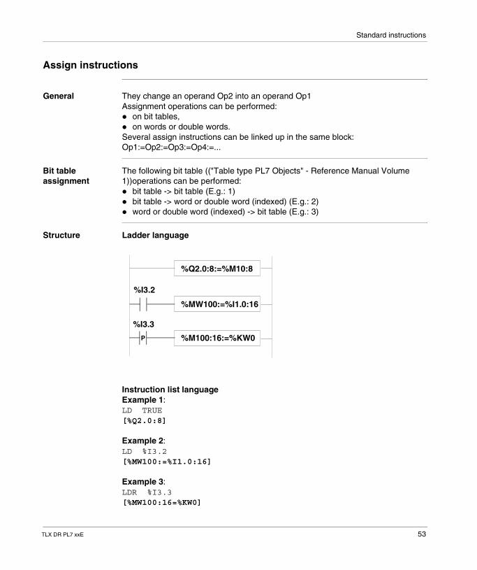
Assign instructions
General They change an operand Op2 into an operand Op1Assignment operations can be performed:� on bit tables,� on words or double words.Several assign instructions can be linked up in the same block: Op1:=Op2:=Op3:=Op4:=...
Bit table assignment
The following bit table (("Table type PL7 Objects" - Reference Manual Volume 1))operations can be performed:� bit table -> bit table (E.g.: 1)� bit table -> word or double word (indexed) (E.g.: 2)� word or double word (indexed) -> bit table (E.g.: 3)
Structure Ladder language
Instruction list languageExample 1:LD TRUE[%Q2.0:8]
Example 2:LD %I3.2[%MW100:=%I1.0:16]
Example 3:LDR %I3.3[%MW100:16=%KW0]
%Q2.0:8:=%M10:8
P
%MW100:=%I1.0:16
%M100:16:=%KW0
%I3.2
%I3.3
TLX DR PL7 xxE 53
Standard instructions
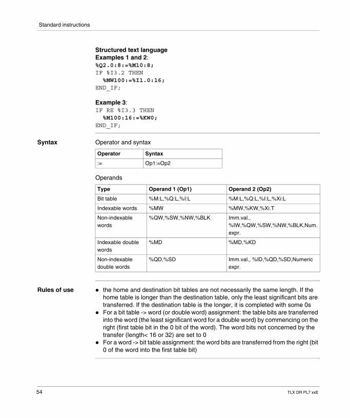
Structured text languageExamples 1 and 2:%Q2.0:8:=%M10:8;IF %I3.2 THEN %MW100:=%I1.0:16;END_IF;
Example 3:IF RE %I3.3 THEN %M100:16:=%KW0;END_IF;
Syntax Operator and syntax
Operands
Rules of use � the home and destination bit tables are not necessarily the same length. If the home table is longer than the destination table, only the least significant bits are transferred. If the destination table is the longer, it is completed with some 0s
� For a bit table -> word (or double word) assignment: the table bits are transferred into the word (the least significant word for a double word) by commencing on the right (first table bit in the 0 bit of the word). The word bits not concerned by the transfer (length< 16 or 32) are set to 0
� For a word -> bit table assignment: the word bits are transferred from the right (bit 0 of the word into the first table bit)
Operator Syntax
:= Op1:=Op2
Type Operand 1 (Op1) Operand 2 (Op2)
Bit table %M:L,%Q:L,%I:L %M:L,%Q:L,%I:L,%Xi:L
Indexable words %MW %MW,%KW,%Xi.T
Non-indexable words
%QW,%SW,%NW,%BLK Imm.val., %IW,%QW,%SW,%NW,%BLK,Num.expr.
Indexable double words
%MD %MD,%KD
Non-indexable double words
%QD,%SD Imm.val., %ID,%QD,%SD,Numeric expr.
54 TLX DR PL7 xxE
Standard instructions
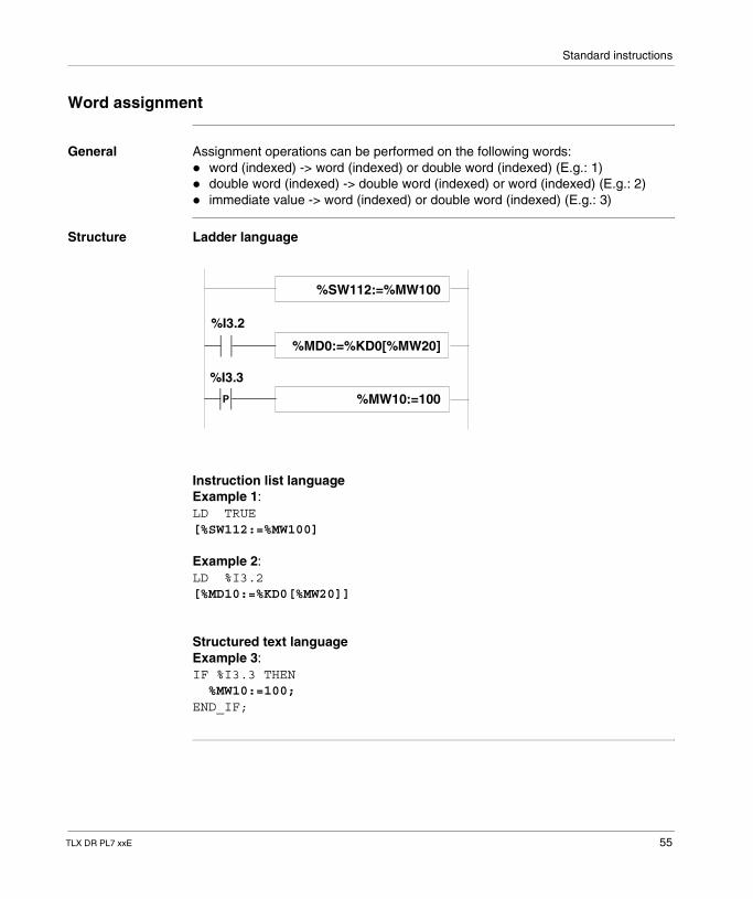
Word assignment
General Assignment operations can be performed on the following words:� word (indexed) -> word (indexed) or double word (indexed) (E.g.: 1)� double word (indexed) -> double word (indexed) or word (indexed) (E.g.: 2)� immediate value -> word (indexed) or double word (indexed) (E.g.: 3)
Structure Ladder language
Instruction list languageExample 1:LD TRUE[%SW112:=%MW100]
Example 2:LD %I3.2[%MD10:=%KD0[%MW20]]
Structured text languageExample 3:IF %I3.3 THEN %MW10:=100;END_IF;
P
%MD0:=%KD0[%MW20]
%MW10:=100
%I3.2
%I3.3
%SW112:=%MW100
TLX DR PL7 xxE 55
Standard instructions
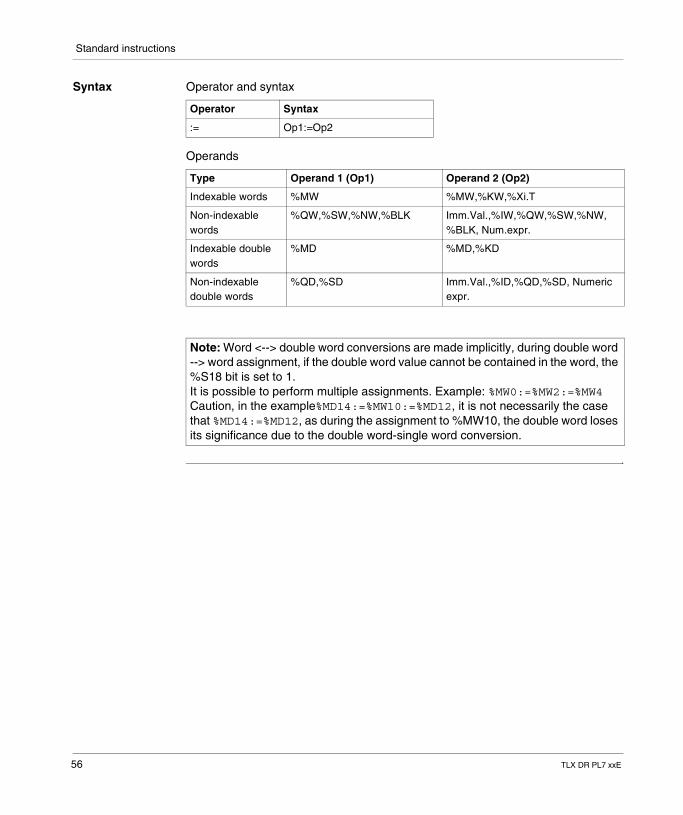
Syntax Operator and syntax
Operands
Operator Syntax
:= Op1:=Op2
Type Operand 1 (Op1) Operand 2 (Op2)
Indexable words %MW %MW,%KW,%Xi.T
Non-indexable words
%QW,%SW,%NW,%BLK Imm.Val.,%IW,%QW,%SW,%NW, %BLK, Num.expr.
Indexable double words
%MD %MD,%KD
Non-indexable double words
%QD,%SD Imm.Val.,%ID,%QD,%SD, Numeric expr.
Note: Word <--> double word conversions are made implicitly, during double word --> word assignment, if the double word value cannot be contained in the word, the %S18 bit is set to 1.It is possible to perform multiple assignments. Example: %MW0:=%MW2:=%MW4Caution, in the example%MD14:=%MW10:=%MD12, it is not necessarily the case that %MD14:=%MD12, as during the assignment to %MW10, the double word loses its significance due to the double word-single word conversion.
56 TLX DR PL7 xxE
Standard instructions
Arithmetic instructions on integers
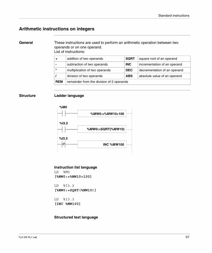
General These instructions are used to perform an arithmetic operation between two operands or on one operand.List of instructions:
Structure Ladder language
Instruction list languageLD %M0[%MW0:=%MW10+100]
LD %I3.2[%MW0:=SQRT(%MW10)]
LD %I3.3[INC %MW100]
Structured text language
+ addition of two operands SQRT square root of an operand
- subtraction of two operands INC incrementation of an operand
* multiplication of two operands DEC decrementation of an operand
/ division of two operands ABS absolute value of an operand
REM remainder from the division of 2 operands
P
%MW0:=SQRT(%MW10)
INC %MW100
%I3.2
%I3.3
%MW0:=%MW10+100
%M0
TLX DR PL7 xxE 57
Standard instructions
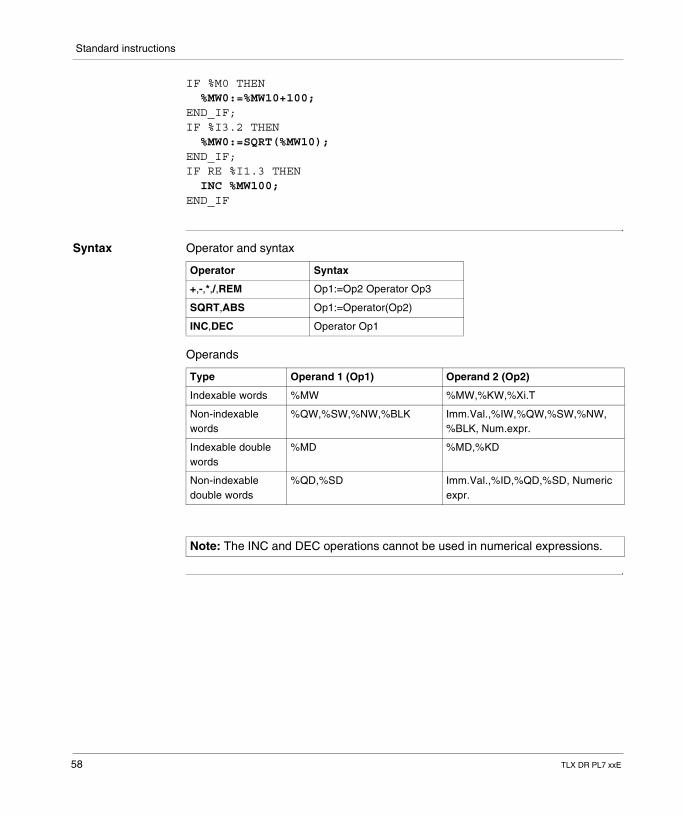
IF %M0 THEN %MW0:=%MW10+100;END_IF;IF %I3.2 THEN %MW0:=SQRT(%MW10);END_IF;IF RE %I1.3 THEN INC %MW100;END_IF
Syntax Operator and syntax
Operands
Operator Syntax
+,-,*,/,REM Op1:=Op2 Operator Op3
SQRT,ABS Op1:=Operator(Op2)
INC,DEC Operator Op1
Type Operand 1 (Op1) Operand 2 (Op2)
Indexable words %MW %MW,%KW,%Xi.T
Non-indexable words
%QW,%SW,%NW,%BLK Imm.Val.,%IW,%QW,%SW,%NW, %BLK, Num.expr.
Indexable double words
%MD %MD,%KD
Non-indexable double words
%QD,%SD Imm.Val.,%ID,%QD,%SD, Numeric expr.
Note: The INC and DEC operations cannot be used in numerical expressions.
58 TLX DR PL7 xxE
Standard instructions
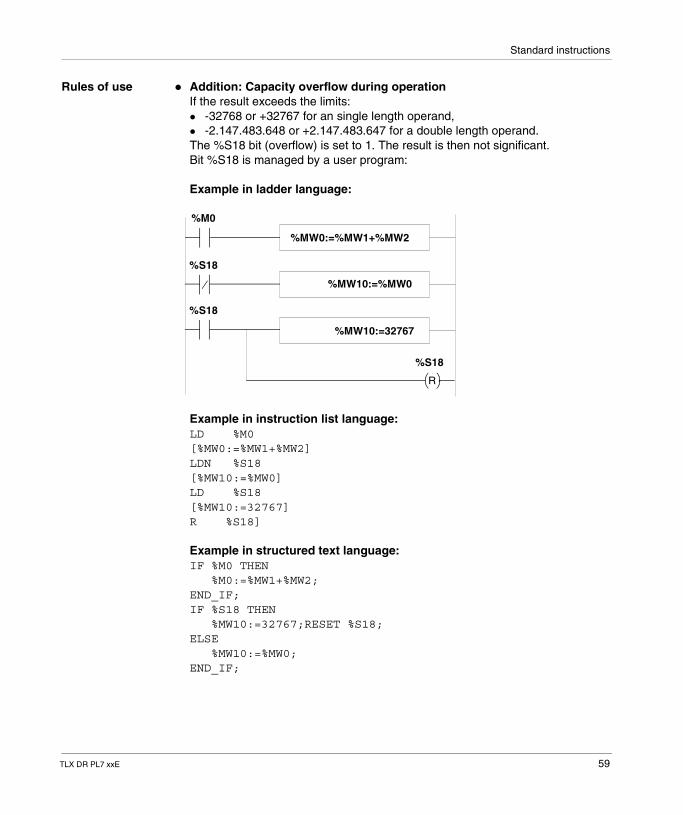
Rules of use � Addition: Capacity overflow during operationIf the result exceeds the limits:� -32768 or +32767 for an single length operand,� -2.147.483.648 or +2.147.483.647 for a double length operand.The %S18 bit (overflow) is set to 1. The result is then not significant. Bit %S18 is managed by a user program:
Example in ladder language:
Example in instruction list language:LD %M0[%MW0:=%MW1+%MW2]LDN %S18[%MW10:=%MW0]LD %S18[%MW10:=32767]R %S18]
Example in structured text language:IF %M0 THEN %M0:=%MW1+%MW2;END_IF;IF %S18 THEN %MW10:=32767;RESET %S18;ELSE %MW10:=%MW0;END_IF;
%MW0:=%MW1+%MW2
%MW10:=%MW0
%MW10:=32767
R
%S18
%M0
%S18
%S18
TLX DR PL7 xxE 59
Standard instructions
If %MW1 =23241 and %MW2=21853, the integer result (45094) cannot be expressed in a 16 bit word, bit %S18 is set to 1 and the result obtained (-20442) is incorrect. In this example, when the result is greater than 32767, its value is fixed at 32767.
� Multiplication:Capacity overflow during operation.If the result exceeds the storage word capacity, the %S18 bit (overflow) is set to 1 and the result is not significant.
� Division/remainder of the division:Dividing by 0.If the divisor is equal to 0, division is impossible and the %S18 system bit is set to 1. The result is then incorrect.Capacity overflow during operation.
� Extracting the square root:The square root can only be extracted on positive values. The result is then always positive. If the operand of the square root is negative, the %S18 system bit is set to 1 and the result is incorrect.
Note: � When an operation does not result in an integer (i.e. with a division or square
root), the result is truncated (rounded down to the nearest whole number).� The sign of the remainder of the division (REM) is that of the numerator.� The %S18 system bit is managed by the user program. It is set to 1 by the PLC.
It must be reset to 0 by the program in order to be reused (see example below).
60 TLX DR PL7 xxE
Standard instructions
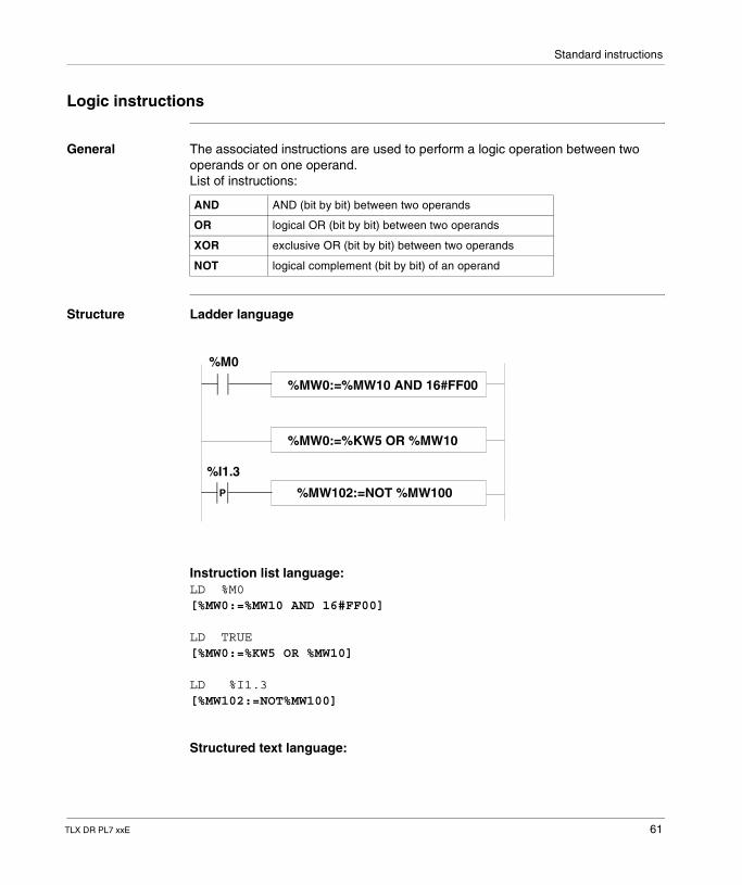
Logic instructions
General The associated instructions are used to perform a logic operation between two operands or on one operand.List of instructions:
Structure Ladder language
Instruction list language:LD %M0[%MW0:=%MW10 AND 16#FF00]
LD TRUE[%MW0:=%KW5 OR %MW10]
LD %I1.3[%MW102:=NOT%MW100]
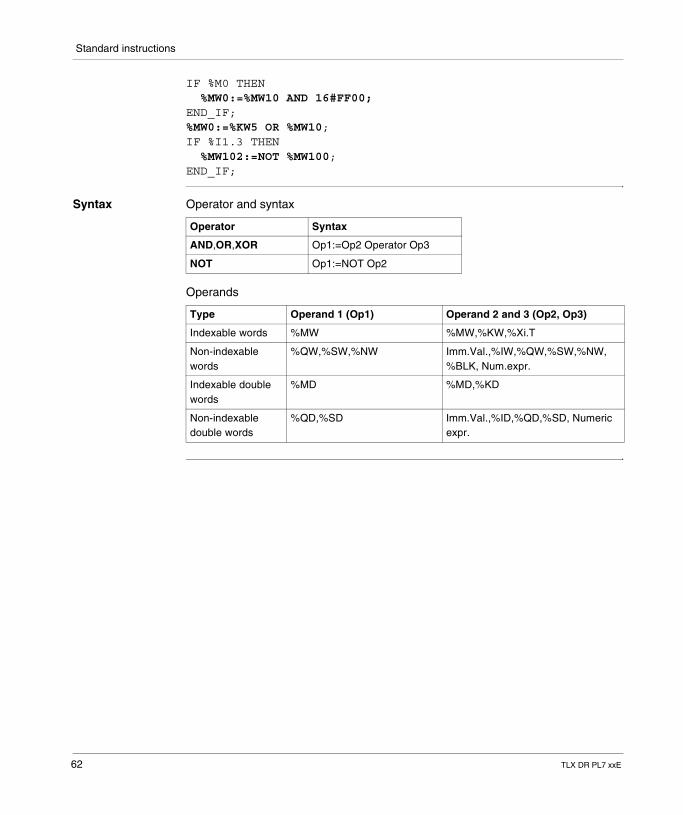
Structured text language:
AND AND (bit by bit) between two operands
OR logical OR (bit by bit) between two operands
XOR exclusive OR (bit by bit) between two operands
NOT logical complement (bit by bit) of an operand
P
%MW0:=%KW5 OR %MW10
%MW102:=NOT %MW100
%I1.3
%MW0:=%MW10 AND 16#FF00
%M0
TLX DR PL7 xxE 61
Standard instructions
IF %M0 THEN %MW0:=%MW10 AND 16#FF00;END_IF;%MW0:=%KW5 OR %MW10;IF %I1.3 THEN %MW102:=NOT %MW100;END_IF;
Syntax Operator and syntax
Operands
Operator Syntax
AND,OR,XOR Op1:=Op2 Operator Op3
NOT Op1:=NOT Op2
Type Operand 1 (Op1) Operand 2 and 3 (Op2, Op3)
Indexable words %MW %MW,%KW,%Xi.T
Non-indexable words
%QW,%SW,%NW Imm.Val.,%IW,%QW,%SW,%NW, %BLK, Num.expr.
Indexable double words
%MD %MD,%KD
Non-indexable double words
%QD,%SD Imm.Val.,%ID,%QD,%SD, Numeric expr.
62 TLX DR PL7 xxE
Standard instructions
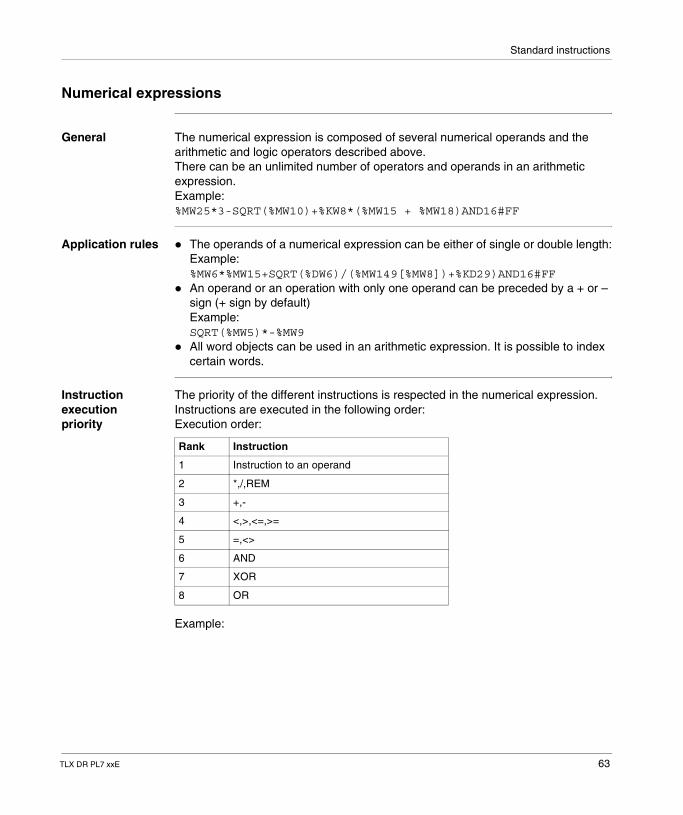
Numerical expressions
General The numerical expression is composed of several numerical operands and the arithmetic and logic operators described above.There can be an unlimited number of operators and operands in an arithmetic expression.Example: %MW25*3-SQRT(%MW10)+%KW8*(%MW15 + %MW18)AND16#FF
Application rules � The operands of a numerical expression can be either of single or double length:Example: %MW6*%MW15+SQRT(%DW6)/(%MW149[%MW8])+%KD29)AND16#FF
� An operand or an operation with only one operand can be preceded by a + or – sign (+ sign by default)Example: SQRT(%MW5)*-%MW9
� All word objects can be used in an arithmetic expression. It is possible to index certain words.
Instruction execution priority
The priority of the different instructions is respected in the numerical expression. Instructions are executed in the following order:Execution order:
Example:
Rank Instruction
1 Instruction to an operand
2 *,/,REM
3 +,-
4 <,>,<=,>=
5 =,<>
6 AND
7 XOR
8 OR
TLX DR PL7 xxE 63
Standard instructions
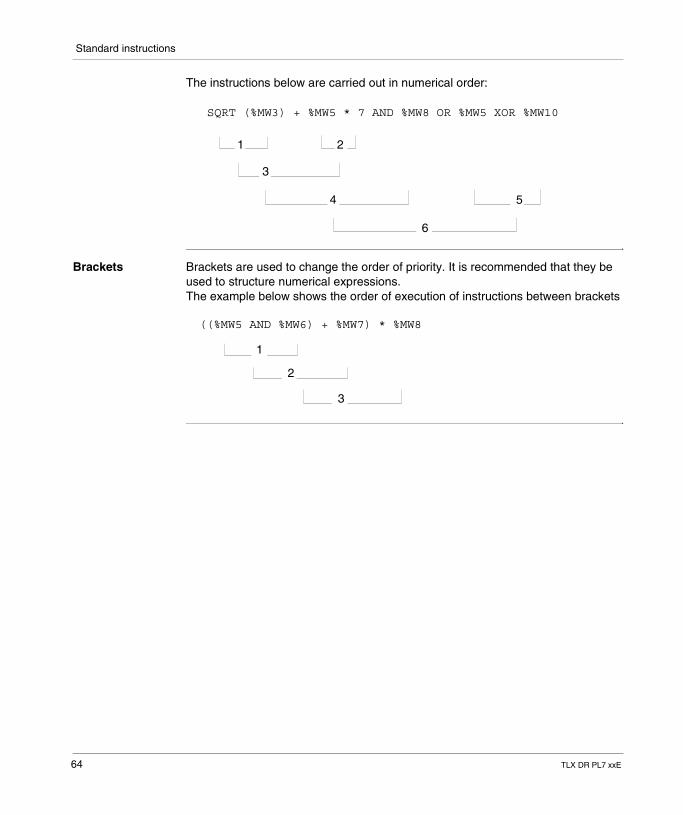
The instructions below are carried out in numerical order:
Brackets Brackets are used to change the order of priority. It is recommended that they be used to structure numerical expressions.The example below shows the order of execution of instructions between brackets
SQRT (%MW3) + %MW5 * 7 AND %MW8 OR %MW5 XOR %MW10
1 2
3
4 5
6
((%MW5 AND %MW6) + %MW7) * %MW8
1
2
3
64 TLX DR PL7 xxE
Standard instructions
1.5 Program instructions
Introduction
Aim of this sub-section
This sub-section describes PL7 language program instructions.
What's in this Section?
This Section contains the following Maps:
Topic Page
Subroutine call 66
Subroutine return 68
Jump in the program 70
End of program instructions 73
Program stop 75
Event masking/unmasking instructions 76
NOP Instructions 77
TLX DR PL7 xxE 65
Standard instructions
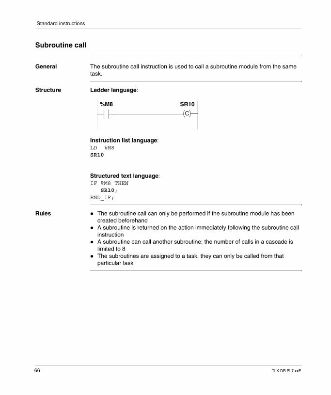
Subroutine call
General The subroutine call instruction is used to call a subroutine module from the same task.
Structure Ladder language:
Instruction list language:LD %M8SR10
Structured text language:IF %M8 THEN SR10;END_IF;
Rules � The subroutine call can only be performed if the subroutine module has been created beforehand
� A subroutine is returned on the action immediately following the subroutine call instruction
� A subroutine can call another subroutine; the number of calls in a cascade is limited to 8
� The subroutines are assigned to a task, they can only be called from that particular task
C
%M8 SR10
66 TLX DR PL7 xxE
Standard instructions
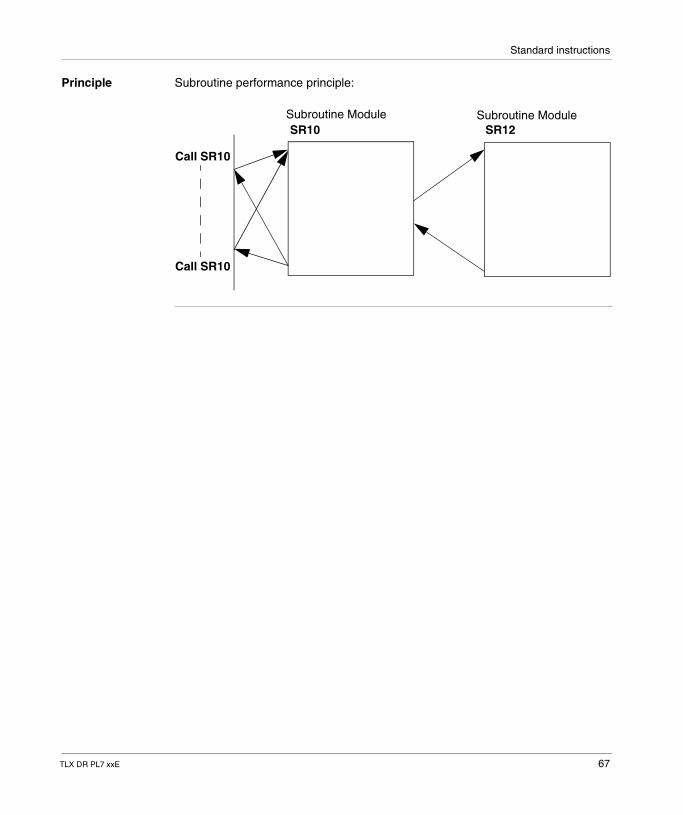
Principle Subroutine performance principle:
Subroutine Module Subroutine ModuleSR10 SR12
Call SR10
Call SR10
TLX DR PL7 xxE 67
Standard instructions
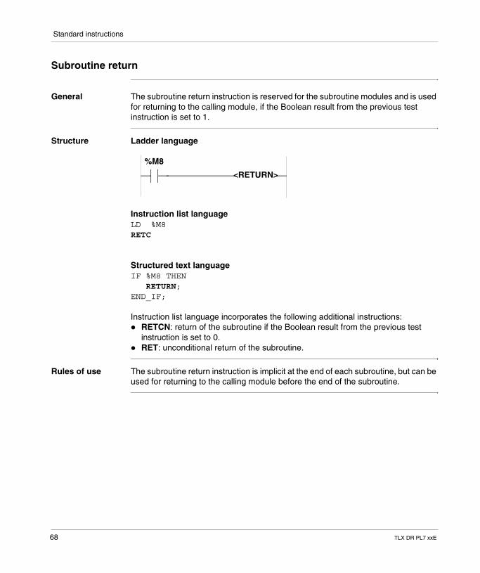
Subroutine return
General The subroutine return instruction is reserved for the subroutine modules and is used for returning to the calling module, if the Boolean result from the previous test instruction is set to 1.
Structure Ladder language
Instruction list languageLD %M8RETC
Structured text languageIF %M8 THEN RETURN;END_IF;
Instruction list language incorporates the following additional instructions:� RETCN: return of the subroutine if the Boolean result from the previous test
instruction is set to 0.� RET: unconditional return of the subroutine.
Rules of use The subroutine return instruction is implicit at the end of each subroutine, but can be used for returning to the calling module before the end of the subroutine.
%M8
<RETURN>
68 TLX DR PL7 xxE
Standard instructions
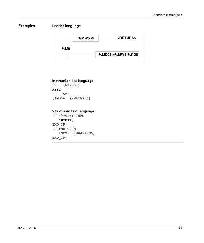
Examples Ladder language
Instruction list languageLD [%MW5>3]RETCLD %M8[%MD26:=%MW4*%KD6]
Structured text languageIF (%M5>3) THEN RETURN;END_IF;IF %M8 THEN %MD26:=%MW4*%KD6;END_IF;
%MW5>3 <RETURN>
%MD26:=%MW4*%KD6
%M8
TLX DR PL7 xxE 69
Standard instructions
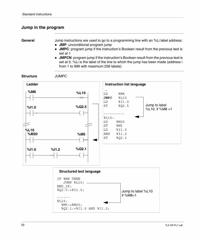
Jump in the program
General Jump instructions are used to go to a programming line with an %Li label address:� JMP: unconditional program jump� JMPC: program jump if the instruction’s Boolean result from the previous test is
set at 1� JMPCN: program jump if the instruction’s Boolean result from the previous test is
set at 0. %Li is the label of the line to which the jump has been made (address i from 1 to 999 with maximum 256 labels)
Structure JUMPC
>>%L10
%Q2.5%I1.0
%M8
%M5
%Q2.1%I1.0
%M20%L10
%I1.2
LD %M8JMPC %L10LD %I1.0ST %Q2.5
----------%L10:LD %M20ST %M5LD %I1.0AND %I1.2ST %Q2.1
Jump to label%L10, if %M8 =1
Ladder Instruction list language
IF %M8 THEN JUMP %L10;END_IF;%Q2.5:=%I1.0;
------%L10: %M5:=%M20; %Q2.1:=%I1.0 AND %I1.2;
Jump to label %L10if %M8=1
Structured text language
_
70 TLX DR PL7 xxE
Standard instructions
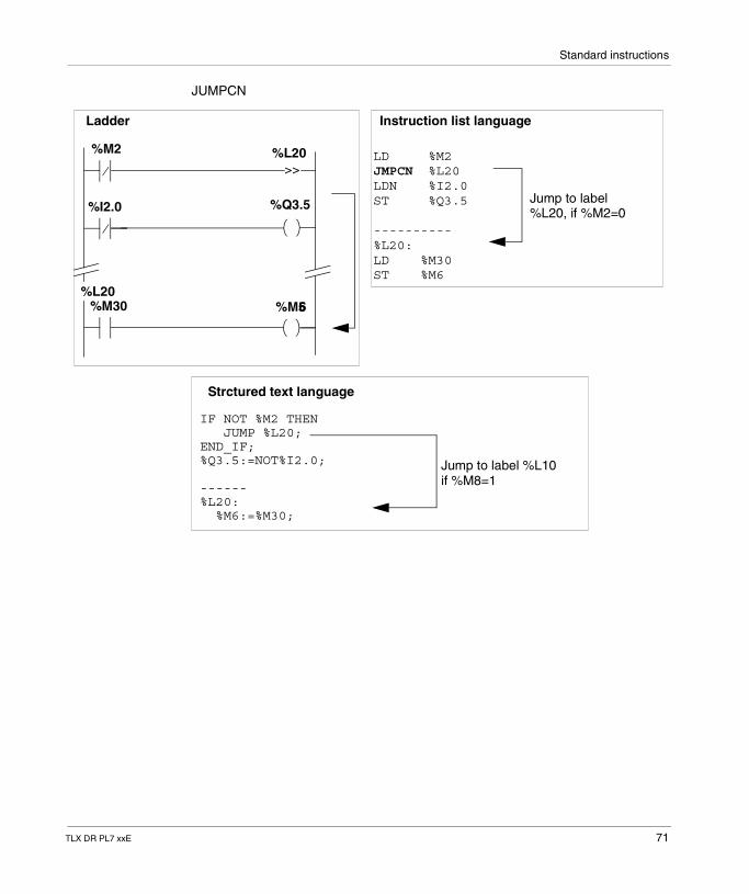
JUMPCN
>>%L20
%Q3.5%I2.0
%M2
%M5%M30%L20
LD %M2JMPCN %L20LDN %I2.0ST %Q3.5
----------%L20:LD %M30ST %M6
Jump to label%L20, if %M2=0
Ladder Instruction list language
IF NOT %M2 THEN JUMP %L20;END_IF;%Q3.5:=NOT%I2.0;
------%L20: %M6:=%M30;
Jump to label %L10if %M8=1
Strctured text language
6
TLX DR PL7 xxE 71
Standard instructions
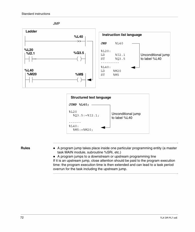
JMP
Rules � A program jump takes place inside one particular programming entity (a master task MAIN module, subroutine %SRi, etc.)
� A program jumps to a downstream or upstream programming lineIf it is an upstream jump, close attention should be paid to the program execution time: the program execution time is then extended and can lead to a task period overrun for the task including the upstream jump.
>>%L40
%Q3.5%I2.1
%M5%M20%L40
JMP %L40
%L20:
ST %Q3.5
%L40:LD %M20ST %M5
Unconditional jump
LadderInstruction list language
JUMP %L40; %L20 %Q3.5:=%I2.1;
------%L40: %M5:=%M20;
Unconditional jumpto label %L40
Structured text language
5
%L20LD %I2.1
---------to label %L40
72 TLX DR PL7 xxE
Standard instructions
End of program instructions
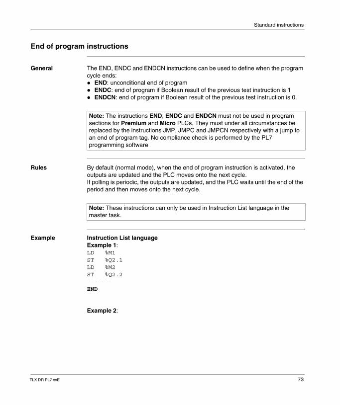
General The END, ENDC and ENDCN instructions can be used to define when the program cycle ends:� END: unconditional end of program� ENDC: end of program if Boolean result of the previous test instruction is 1� ENDCN: end of program if Boolean result of the previous test instruction is 0.
Rules By default (normal mode), when the end of program instruction is activated, the outputs are updated and the PLC moves onto the next cycle.If polling is periodic, the outputs are updated, and the PLC waits until the end of the period and then moves onto the next cycle.
Example Instruction List languageExample 1:LD %M1ST %Q2.1LD %M2ST %Q2.2-------END
Example 2:
Note: The instructions END, ENDC and ENDCN must not be used in program sections for Premium and Micro PLCs. They must under all circumstances be replaced by the instructions JMP, JMPC and JMPCN respectively with a jump to an end of program tag. No compliance check is performed by the PL7 programming software
Note: These instructions can only be used in Instruction List language in the master task.
TLX DR PL7 xxE 73
Standard instructions
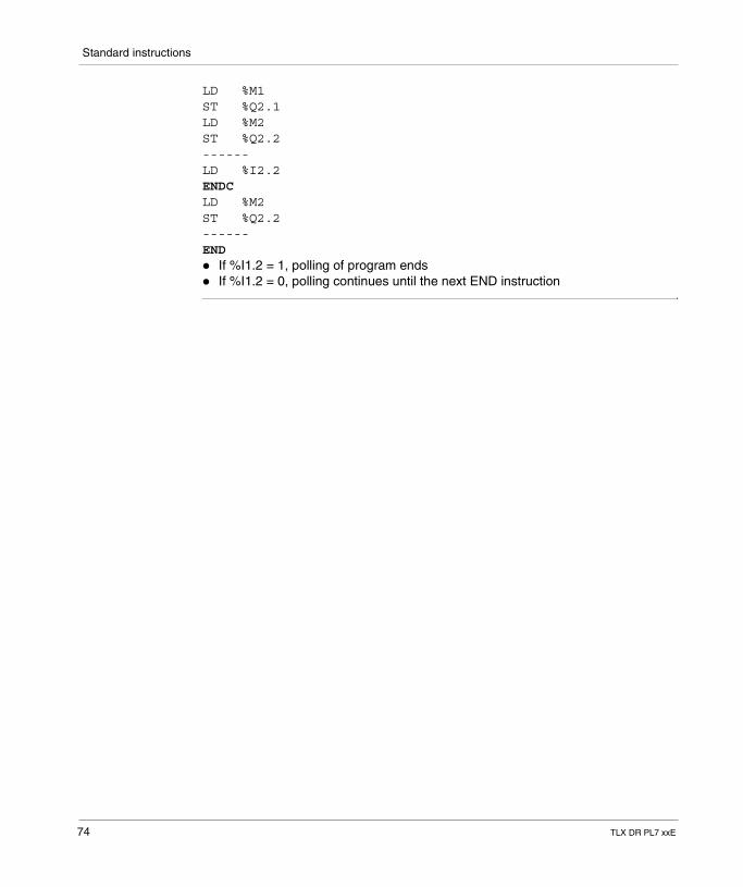
LD %M1ST %Q2.1LD %M2ST %Q2.2------LD %I2.2ENDCLD %M2ST %Q2.2------END� If %I1.2 = 1, polling of program ends� If %I1.2 = 0, polling continues until the next END instruction
74 TLX DR PL7 xxE
Standard instructions
Program stop
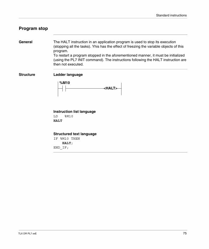
General The HALT instruction in an application program is used to stop its execution (stopping all the tasks). Yhis has the effect of freezing the variable objects of this program.To restart a program stopped in the aforementioned manner, it must be initialized (using the PL7 INIT command). The instructions following the HALT instruction are then not executed.
Structure Ladder language
Instruction list languageLD %M10HALT
Structured text languageIF %M10 THEN HALT;END_IF;
<HALT>%M10
TLX DR PL7 xxE 75
Standard instructions
Event masking/unmasking instructions
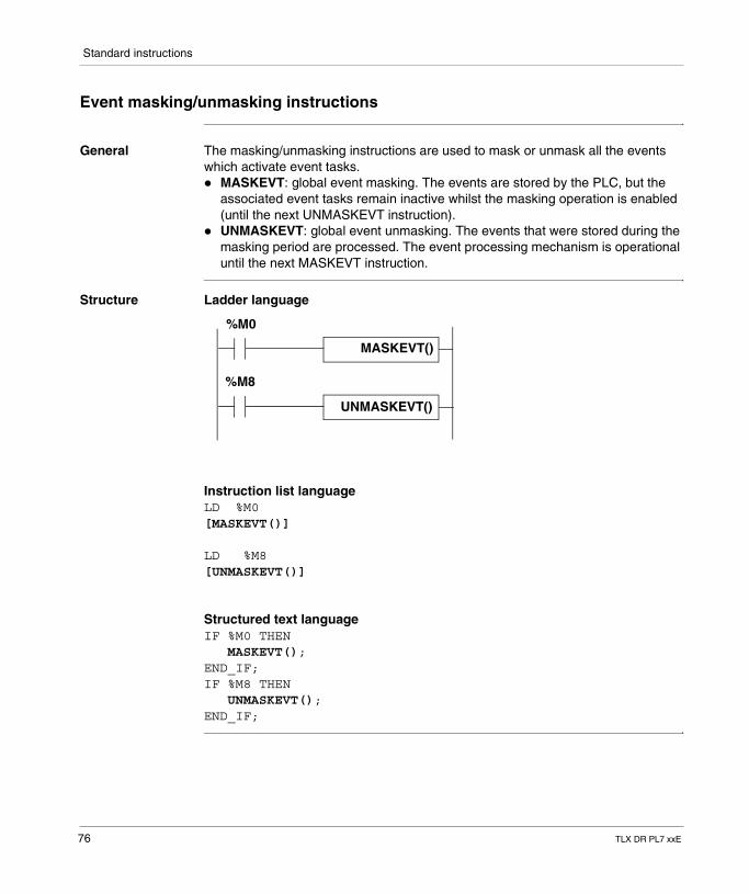
General The masking/unmasking instructions are used to mask or unmask all the events which activate event tasks.� MASKEVT: global event masking. The events are stored by the PLC, but the
associated event tasks remain inactive whilst the masking operation is enabled (until the next UNMASKEVT instruction).
� UNMASKEVT: global event unmasking. The events that were stored during the masking period are processed. The event processing mechanism is operational until the next MASKEVT instruction.
Structure Ladder language
Instruction list languageLD %M0[MASKEVT()]
LD %M8[UNMASKEVT()]
Structured text languageIF %M0 THEN MASKEVT();END_IF;IF %M8 THEN UNMASKEVT();END_IF;
UNMASKEVT()
%M0
%M8
MASKEVT()
76 TLX DR PL7 xxE
Standard instructions
NOP Instructions
General The NOP instruction does not perform any action. It is used to "reserve" lines in a program and thus makes it possible to write instructions without any modification of line numbers.
TLX DR PL7 xxE 77

Standard instructions
78 TLX DR PL7 xxE
TLX DR PL7 xxE
2
Advanced instructionsIntroduction
Contents of this section
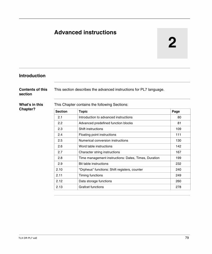
This section describes the advanced instructions for PL7 language.
What's in this Chapter?
This Chapter contains the following Sections:
Section Topic Page
2.1 Introduction to advanced instructions 80
2.2 Advanced predefined function blocks 81
2.3 Shift instructions 109
2.4 Floating point instructions 111
2.5 Numerical conversion instructions 130
2.6 Word table instructions 142
2.7 Character string instructions 167
2.8 Time management instructions: Dates, Times, Duration 199
2.9 Bit table instructions 232
2.10 "Orpheus" functions: Shift registers, counter 240
2.11 Timing functions 249
2.12 Data storage functions 260
2.13 Grafcet functions 278
79
Advanced instructions
2.1 Introduction to advanced instructions
Introduction to the advanced instructions
General The instructions described in this chapter are intended for advanced programming needs.They have the same effects in any language. Only the syntax is different.
These are:� either standard software instructions,� or functions considered as extensions of the software.
Instructions for the Function type ranges are used to enhance the basic software using specific programming instructions.� Operations on character strings, word tables, etc.� Task functions: Communication, Regulation, Operator dialog, etc.
Instruction families
They consist of the following families:� Character strings,� Integer tables,� Managing dates, times, periods,� Conversions,� Bit tables,� "Orpheus" functions.
The following families are described in the tasks concerned:� Communication,� Regulation,� Operator dialog,� Movement command.
Note: Function type instructions imply additional application memory occupation (only when they are actually used in the program). This memory occupation is to be taken into account by the programmer for each function, whatever their user number, and this is in accordance with the maximum memory size of the reserve PLC.
80 TLX DR PL7 xxE
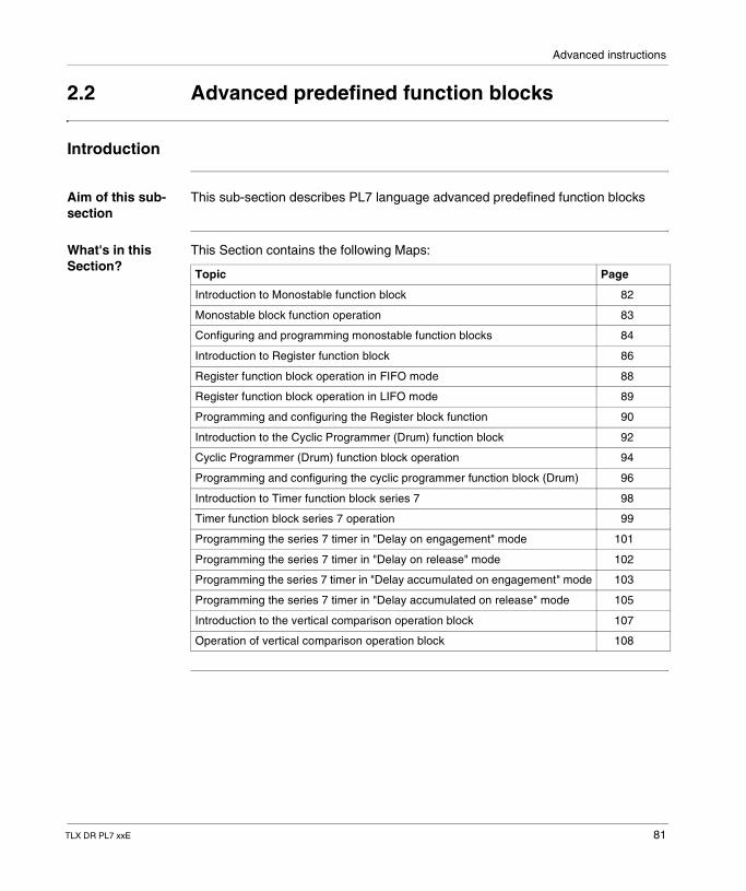
Advanced instructions
2.2 Advanced predefined function blocks
Introduction
Aim of this sub-section
This sub-section describes PL7 language advanced predefined function blocks
What's in this Section?
This Section contains the following Maps:
Topic Page
Introduction to Monostable function block 82
Monostable block function operation 83
Configuring and programming monostable function blocks 84
Introduction to Register function block 86
Register function block operation in FIFO mode 88
Register function block operation in LIFO mode 89
Programming and configuring the Register block function 90
Introduction to the Cyclic Programmer (Drum) function block 92
Cyclic Programmer (Drum) function block operation 94
Programming and configuring the cyclic programmer function block (Drum) 96
Introduction to Timer function block series 7 98
Timer function block series 7 operation 99
Programming the series 7 timer in "Delay on engagement" mode 101
Programming the series 7 timer in "Delay on release" mode 102
Programming the series 7 timer in "Delay accumulated on engagement" mode 103
Programming the series 7 timer in "Delay accumulated on release" mode 105
Introduction to the vertical comparison operation block 107
Operation of vertical comparison operation block 108
TLX DR PL7 xxE 81
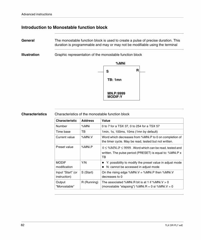
Advanced instructions
Introduction to Monostable function block
General The monostable function block is used to create a pulse of precise duration. This duration is programmable and may or may not be modifiable using the terminal
Illustration Graphic representation of the monostable function block
Characteristics Characteristics of the monostable function block
S R
TB: 1mn
MN.P:9999MODIF:Y
%MNi
Characteristic Address Value
Number %MNi 0 to 7 for a TSX 37, 0 to 254 for a TSX 57
Time base TB 1min, 1s, 100ms, 10ms (1mn by default)
Current value %MNi.V Word which decreases from %MNi.P to 0 on completion of the timer cycle. May be read, tested but not written.
Preset value %MNi.P . Word which can be read, tested and
written. The pulse period (PRESET) is equal to: %MNi.P x TB
MODIF modification
Y/N � Y: possibility to modify the preset value in adjust mode� N: cannot be accessed in adjust mode
Input "Start" (or instruction)
S (Start) On the rising edge %MNi.V = %MNi.P then %MNi.V decreases to 0
Output "Monostable"
R (Running) The associated %MNi.R bit is at 1 if %MNi.V > 0 (monostable "elapsing") %MNi.R = 0 si %MNi.V = 0
0 %MNi.P 9999≤ ≤
82 TLX DR PL7 xxE
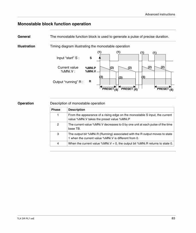
Advanced instructions
Monostable block function operation
General The monostable function block is used to generate a pulse of precise duration.
Illustration Timing diagram illustrating the monostable operation
Operation Description of monostable operation
PRESET PRESET PRESET
S
%MNi.P%MNi.V
R
Input “start” S :
Current value%MNi.V :
Output “running” R :
(1)
(2)
(3)
(1) (1) (1)
(2) (2) (2)
(3) (3)
(4) (4) (4)
Phase Description
1 From the appearance of a rising edge on the monostable S input, the current value %MNi.V takes the preset value %MNi.P
2 The current value %MNi.V decreases to 0 by one unit at each pulse of the time base TB.
3 The output bit %MNi.R (Running) associated with the R output moves to state 1 when the current value %MNi.V is different from 0.
4 When the current value %MNi.V = 0, the output bit %MNi.R returns to state 0.
TLX DR PL7 xxE 83
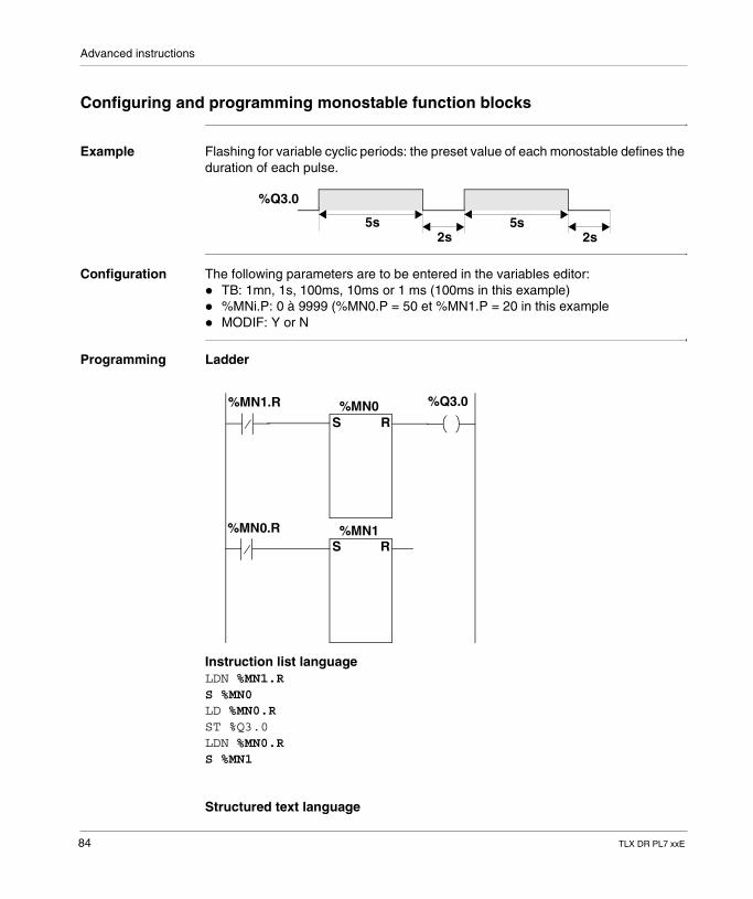
Advanced instructions
Configuring and programming monostable function blocks
Example Flashing for variable cyclic periods: the preset value of each monostable defines the duration of each pulse.
Configuration The following parameters are to be entered in the variables editor:� TB: 1mn, 1s, 100ms, 10ms or 1 ms (100ms in this example)� %MNi.P: 0 à 9999 (%MN0.P = 50 et %MN1.P = 20 in this example� MODIF: Y or N
Programming Ladder
Instruction list languageLDN %MN1.RS %MN0LD %MN0.RST %Q3.0LDN %MN0.RS %MN1
Structured text language
5s 5s2s 2s
%Q3.0
S R
S R
%MN1.R %MN0 %Q3.0
%MN0.R %MN1
84 TLX DR PL7 xxE
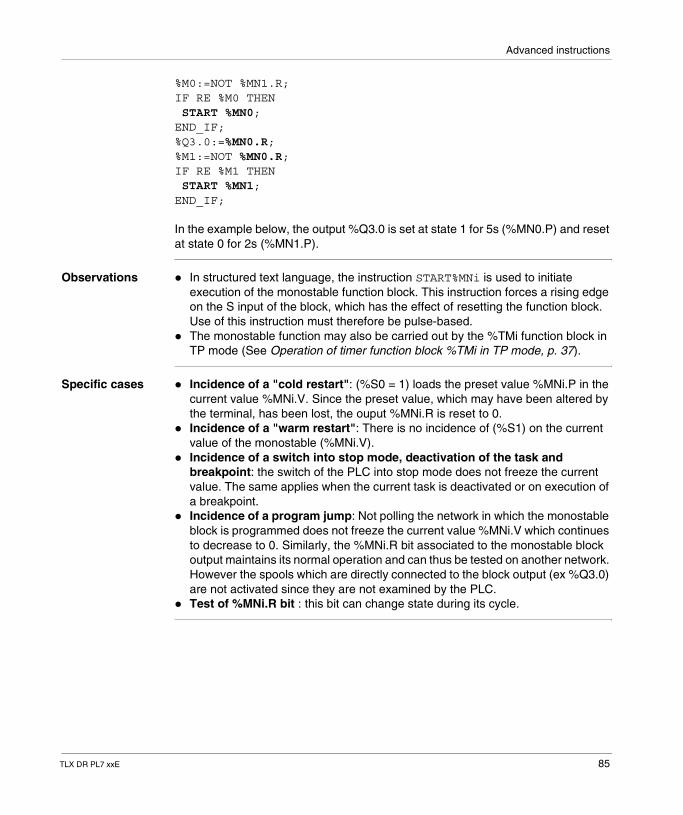
Advanced instructions
%M0:=NOT %MN1.R;IF RE %M0 THEN START %MN0;END_IF;%Q3.0:=%MN0.R;%M1:=NOT %MN0.R;IF RE %M1 THEN START %MN1;END_IF;
In the example below, the output %Q3.0 is set at state 1 for 5s (%MN0.P) and reset at state 0 for 2s (%MN1.P).
Observations � In structured text language, the instruction START%MNi is used to initiate execution of the monostable function block. This instruction forces a rising edge on the S input of the block, which has the effect of resetting the function block. Use of this instruction must therefore be pulse-based.
� The monostable function may also be carried out by the %TMi function block in TP mode (See Operation of timer function block %TMi in TP mode, p. 37).
Specific cases � Incidence of a "cold restart": (%S0 = 1) loads the preset value %MNi.P in the current value %MNi.V. Since the preset value, which may have been altered by the terminal, has been lost, the ouput %MNi.R is reset to 0.
� Incidence of a "warm restart": There is no incidence of (%S1) on the current value of the monostable (%MNi.V).
� Incidence of a switch into stop mode, deactivation of the task and breakpoint: the switch of the PLC into stop mode does not freeze the current value. The same applies when the current task is deactivated or on execution of a breakpoint.
� Incidence of a program jump: Not polling the network in which the monostable block is programmed does not freeze the current value %MNi.V which continues to decrease to 0. Similarly, the %MNi.R bit associated to the monostable block output maintains its normal operation and can thus be tested on another network. However the spools which are directly connected to the block output (ex %Q3.0) are not activated since they are not examined by the PLC.
� Test of %MNi.R bit : this bit can change state during its cycle.
TLX DR PL7 xxE 85
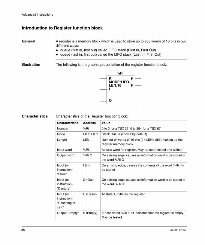
Advanced instructions
Introduction to Register function block
General A register is a memory block which is used to store up to 255 words of 16 bits in two different ways: � queue (first in, first out) called FIFO stack (First In, First Out)� queue (last in, first out) called the LIFO stack (Last In, First Out)
Illustration The following is the graphic presentation of the register function block:
Characteristics Characteristics of the Register function block:
%RiR
I
O
E
FMODE:LIFOLEN:16
Characteristic Address Value
Number %Ri 0 to 3 for a TSX 37, 0 to 254 for a TSX 57
Mode FIFO LIFO Stack Queue (choice by default)
Length LEN Number of words of 16 bits (1< LEN< 255) making up the register memory block.
Input word %Ri.I Access word for register. May be read, tested and written.
Output word %Ri.O On a rising edge, causes an information word to be stored in the word %Ri.O
Input (or instruction) "Store"
I (In) On a rising edge, causes the contents of the word %Ri.I to be stored
Input (or instruction) "Destore"
O (Out) On a rising edge, causes an information word to be stored in the word %Ri.O
Input (or instruction) "Resetting to zero"
R (Reset) At state 1, initiates the register
Output "Empty" E (Empty) E associated %Ri.E bit indicates that the register is empty. May be tested.
86 TLX DR PL7 xxE
Advanced instructions
Output "Full" F (Full) The associated %Ri.F bit indicates that the register is full. May be tested.
Note: When the two inputs I and O are activated simultaneously, storage is carried out before the destocking.
Characteristic Address Value
TLX DR PL7 xxE 87
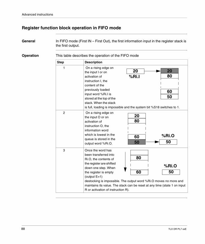
Advanced instructions
Register function block operation in FIFO mode
General In FIFO mode (First IN – First Out), the first information input in the register stack is the first output.
Operation This table describes the operation of the FIFO mode
Step Description
1 On a rising edge on the input I or on activation of instruction I, the content of the previously loaded input word %Ri.I is stored at the top of the stack. When the stack is full, loading is impossible and the system bit %S18 switches to 1.
2 On a rising edge on the input O or on activation of instruction O, the information word which is lowest in the queue is stored in the output word %Ri.O.
3 Once the word has been transferred into Ri.O, the contents of the register are shifted down one step. When the register is empty (output E=1) destocking is impossible. The output word %Ri.O moves no more and maintains its value. The stack can be reset at any time (state 1 on input R or activation of instruction R).
%Ri.I
50
802020
60
50
8020
%Ri.O50
60
80
%Ri.O5060
88 TLX DR PL7 xxE
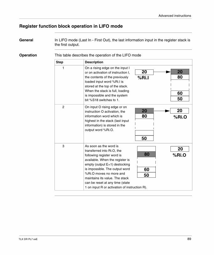
Advanced instructions
Register function block operation in LIFO mode
General In LIFO mode (Last In - First Out), the last information input in the register stack is the first output.
Operation This table describes the operation of the LIFO mode
Step Description
1 On a rising edge on the input I or on activation of instruction I, the contents of the previously loaded input word %Ri.I is stored at the top of the stack. When the stack is full, loading is impossible and the system bit %S18 switches to 1.
2 On input O rising edge or on instruction O activation, the information word which is highest in the stack (last input information) is stored in the output word %Ri.O.
3 As soon as the word is transferred into Ri.O, the following register word is available. When the register is empty (output E=1) destocking is impossible. The output word %Ri.O moves no more and maintains its value. The stack can be reset at any time (state 1 on input R or activation of instruction R).
%Ri.I
50
802020
60
8020
%Ri.O20
50
80 %Ri.O20
5060
TLX DR PL7 xxE 89
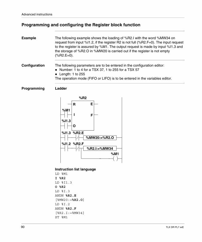
Advanced instructions
Programming and configuring the Register block function
Example The following example shows the loading of %R2.I with the word %MW34 on request from input %I1.2, if the register R2 is not full (%R2.F=0). The input request to the register is assured by %M1. The output request is made by input %I1.3 and the storage of %R2.O in %MW20 is carried out if the register is not empty (%R2.E=0).
Configuration The following parameters are to be entered in the configuration editor:� Number: 1 to 4 for a TSX 37, 1 to 255 for a TSX 57� Length: 1 to 255The operation mode (FIFO or LIFO) is to be entered in the variables editor.
Programming Ladder
Instruction list languageLD %M1I %R2LD %I1.3O %R2LD %I.3ANDN %R2.E[%MW20:=%R2.O]LD %I.2ANDN %R2.F[%R2.I:=%MW34]ST %M1
%R2
R
I
O
E
F%M1
%I1.3
%I1.3 %R2.E
%I1.2 %R2.F
%M1
%MW20:=%R2.O
%R2.I:=%MW34
90 TLX DR PL7 xxE
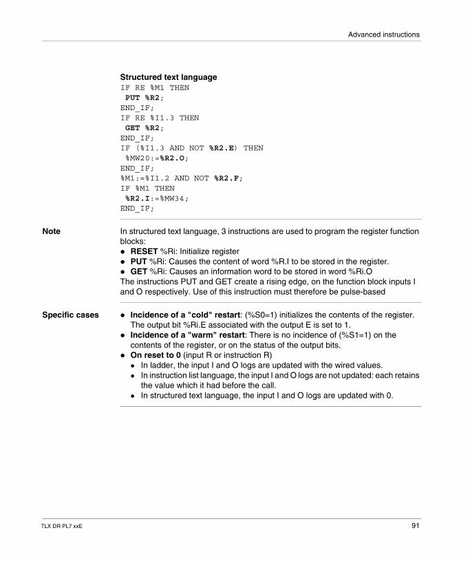
Advanced instructions
Structured text languageIF RE %M1 THEN PUT %R2;END_IF;IF RE %I1.3 THEN GET %R2;END_IF;IF (%I1.3 AND NOT %R2.E) THEN %MW20:=%R2.O;END_IF;%M1:=%I1.2 AND NOT %R2.F;IF %M1 THEN %R2.I:=%MW34;END_IF;
Note In structured text language, 3 instructions are used to program the register function blocks:� RESET %Ri: Initialize register� PUT %Ri: Causes the content of word %R.I to be stored in the register.� GET %Ri: Causes an information word to be stored in word %Ri.OThe instructions PUT and GET create a rising edge, on the function block inputs I and O respectively. Use of this instruction must therefore be pulse-based
Specific cases � Incidence of a "cold" restart: (%S0=1) initializes the contents of the register. The output bit %Ri.E associated with the output E is set to 1.
� Incidence of a "warm" restart: There is no incidence of (%S1=1) on the contents of the register, or on the status of the output bits.
� On reset to 0 (input R or instruction R)� In ladder, the input I and O logs are updated with the wired values.� In instruction list language, the input I and O logs are not updated: each retains
the value which it had before the call.� In structured text language, the input I and O logs are updated with 0.
TLX DR PL7 xxE 91
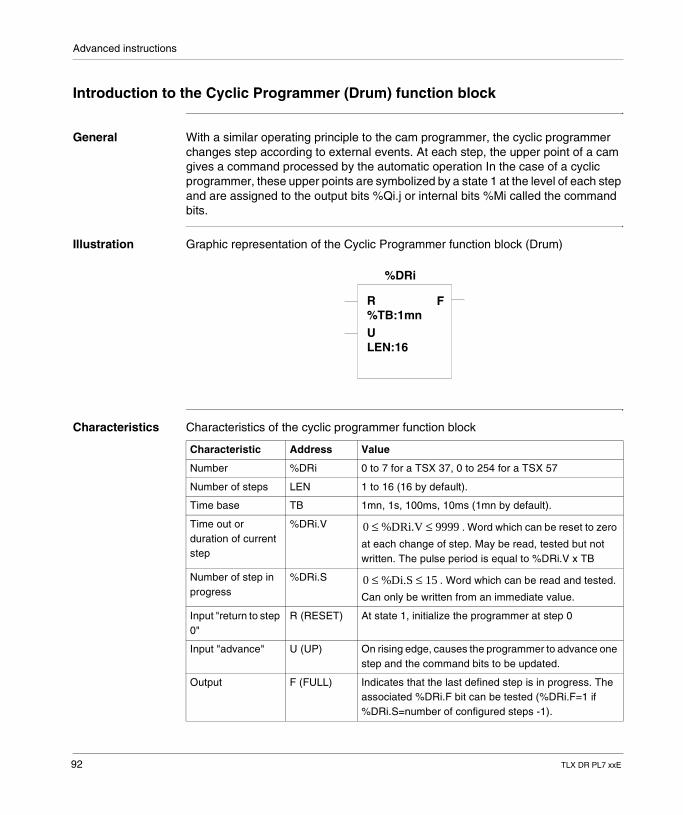
Advanced instructions
Introduction to the Cyclic Programmer (Drum) function block
General With a similar operating principle to the cam programmer, the cyclic programmer changes step according to external events. At each step, the upper point of a cam gives a command processed by the automatic operation In the case of a cyclic programmer, these upper points are symbolized by a state 1 at the level of each step and are assigned to the output bits %Qi.j or internal bits %Mi called the command bits.
Illustration Graphic representation of the Cyclic Programmer function block (Drum)
Characteristics Characteristics of the cyclic programmer function block
%DRi
R
U%TB:1mn
LEN:16
F
Characteristic Address Value
Number %DRi 0 to 7 for a TSX 37, 0 to 254 for a TSX 57
Number of steps LEN 1 to 16 (16 by default).
Time base TB 1mn, 1s, 100ms, 10ms (1mn by default).
Time out or duration of current step
%DRi.V . Word which can be reset to zero
at each change of step. May be read, tested but not written. The pulse period is equal to %DRi.V x TB
Number of step in progress
%DRi.S . Word which can be read and tested.
Can only be written from an immediate value.
Input "return to step 0"
R (RESET) At state 1, initialize the programmer at step 0
Input "advance" U (UP) On rising edge, causes the programmer to advance one step and the command bits to be updated.
Output F (FULL) Indicates that the last defined step is in progress. The associated %DRi.F bit can be tested (%DRi.F=1 if %DRi.S=number of configured steps -1).
0 %DRi.V 9999≤ ≤
0 %Di.S 15≤ ≤
92 TLX DR PL7 xxE
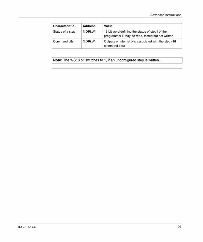
Advanced instructions
Status of a step %DRi.Wj 16 bit word defining the status of step j of the programmer i. May be read, tested but not written.
Command bits %DRi.Wj Outputs or internal bits associated with the step (16 command bits)
Note: The %S18 bit switches to 1, if an unconfigured step is written.
Characteristic Address Value
TLX DR PL7 xxE 93
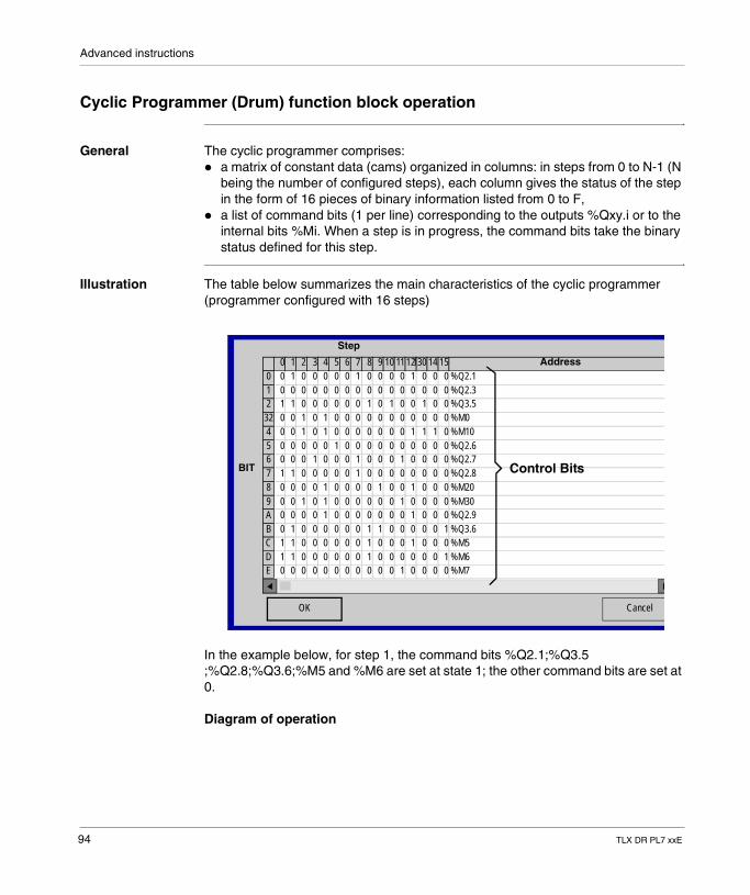
Advanced instructions
Cyclic Programmer (Drum) function block operation
General The cyclic programmer comprises: � a matrix of constant data (cams) organized in columns: in steps from 0 to N-1 (N
being the number of configured steps), each column gives the status of the step in the form of 16 pieces of binary information listed from 0 to F,
� a list of command bits (1 per line) corresponding to the outputs %Qxy.i or to the internal bits %Mi. When a step is in progress, the command bits take the binary status defined for this step.
Illustration The table below summarizes the main characteristics of the cyclic programmer (programmer configured with 16 steps)
In the example below, for step 1, the command bits %Q2.1;%Q3.5 ;%Q2.8;%Q3.6;%M5 and %M6 are set at state 1; the other command bits are set at 0.
Diagram of operation
%DRO Nbr pas : 16
OK Cancel
0 Address1 2 3 4 5 6 7 8 9 10 1112130 14 150 1 0 0 0 0 0 1 0 0 0 0 1 0 0 00 %Q2.10 0 0 0 0 0 0 0 0 0 0 0 0 0 0 01 %Q2.31 1 0 0 0 0 0 0 1 0 1 0 0 1 0 02 %Q3.50 0 1 0 1 0 0 0 0 0 0 0 0 0 0 032 %M00 0 1 0 1 0 0 0 0 0 0 0 1 1 1 04 %M100 0 0 0 0 1 0 0 0 0 0 0 0 0 0 05 %Q2.60 0 0 1 0 0 0 1 0 0 0 1 0 0 0 06 %Q2.71 1 0 0 0 0 0 1 0 0 0 0 0 0 0 07 %Q2.80 0 0 0 1 0 0 0 0 1 0 0 1 0 0 08 %M200 0 1 0 1 0 0 0 0 0 0 1 0 0 0 09 %M300 0 0 0 1 0 0 0 0 0 0 0 1 0 0 0A %Q2.90 1 0 0 0 0 0 0 1 1 0 0 0 0 0 1B %Q3.61 1 0 0 0 0 0 0 1 0 0 0 1 0 0 0C %M51 1 0 0 0 0 0 0 1 0 0 0 0 0 0 1D %M60 0 0 0 0 0 0 0 0 0 0 1 0 0 0 0E %M7
Control Bits
Step
BIT
94 TLX DR PL7 xxE
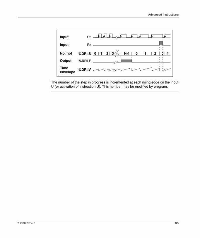
Advanced instructions
The number of the step in progress is incremented at each rising edge on the input U (or activation of instruction U). This number may be modified by program.
0 1 2 3 N-1 0 1 2 0 1
U:
R:
%DRi.S
%DRi.F
%DRi.V
Input
Input
No. not
Output
Timeenvelope
TLX DR PL7 xxE 95
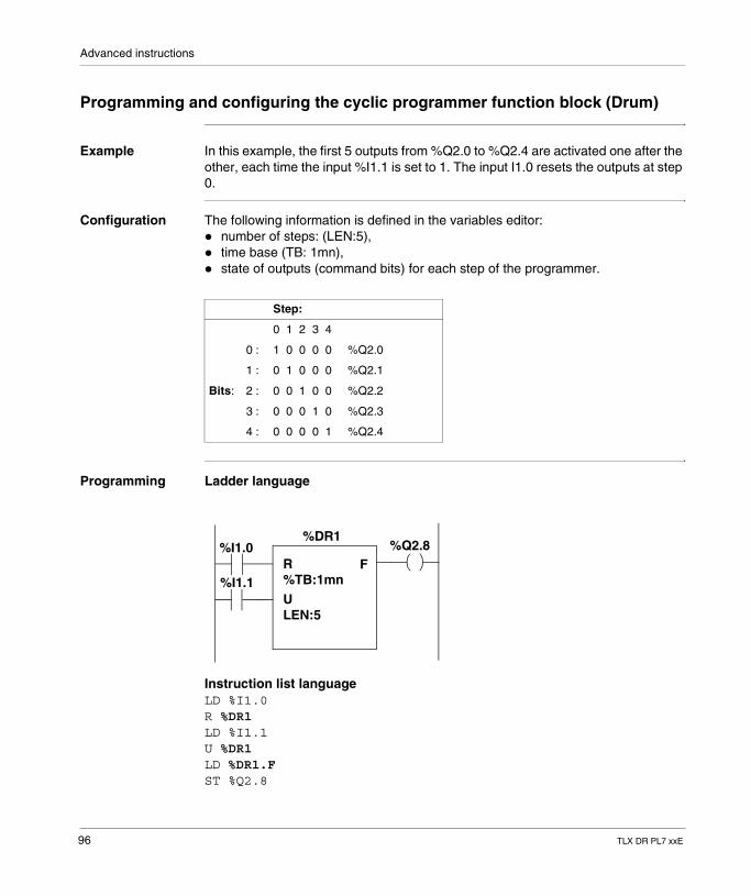
Advanced instructions
Programming and configuring the cyclic programmer function block (Drum)
Example In this example, the first 5 outputs from %Q2.0 to %Q2.4 are activated one after the other, each time the input %I1.1 is set to 1. The input I1.0 resets the outputs at step 0.
Configuration The following information is defined in the variables editor:� number of steps: (LEN:5),� time base (TB: 1mn),� state of outputs (command bits) for each step of the programmer.
Programming Ladder language
Instruction list languageLD %I1.0R %DR1LD %I1.1U %DR1LD %DR1.FST %Q2.8
Step:
0 1 2 3 4
0 : 1 0 0 0 0 %Q2.0
1 : 0 1 0 0 0 %Q2.1
Bits: 2 : 0 0 1 0 0 %Q2.2
3 : 0 0 0 1 0 %Q2.3
4 : 0 0 0 0 1 %Q2.4
%DR1
R
U%TB:1mn
LEN:5
F%I1.0
%I1.1
%Q2.8
96 TLX DR PL7 xxE
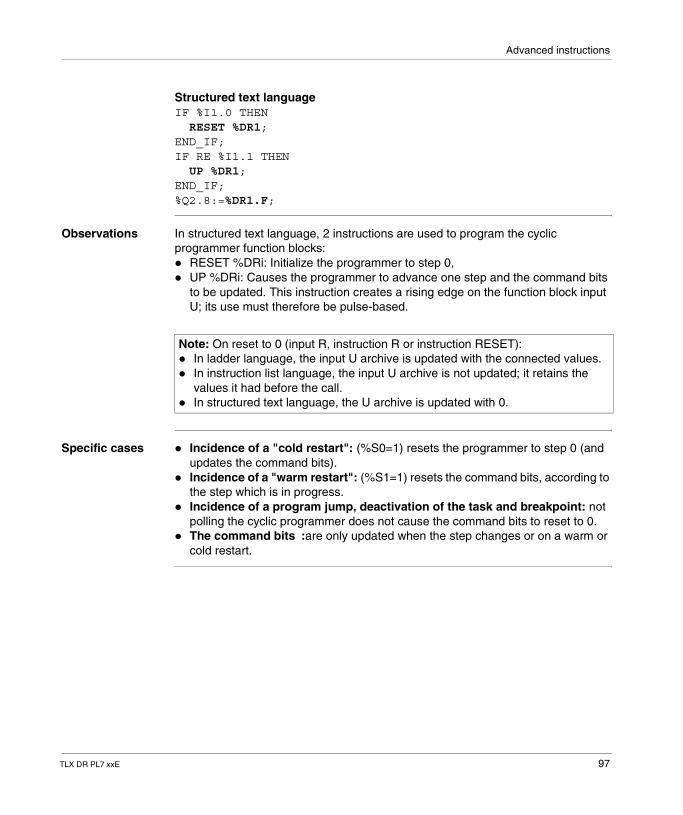
Advanced instructions
Structured text languageIF %I1.0 THEN RESET %DR1;END_IF;IF RE %I1.1 THEN UP %DR1;END_IF;%Q2.8:=%DR1.F;
Observations In structured text language, 2 instructions are used to program the cyclic programmer function blocks:� RESET %DRi: Initialize the programmer to step 0,� UP %DRi: Causes the programmer to advance one step and the command bits
to be updated. This instruction creates a rising edge on the function block input U; its use must therefore be pulse-based.
Specific cases � Incidence of a "cold restart": (%S0=1) resets the programmer to step 0 (and updates the command bits).
� Incidence of a "warm restart": (%S1=1) resets the command bits, according to the step which is in progress.
� Incidence of a program jump, deactivation of the task and breakpoint: not polling the cyclic programmer does not cause the command bits to reset to 0.
� The command bits :are only updated when the step changes or on a warm or cold restart.
Note: On reset to 0 (input R, instruction R or instruction RESET):� In ladder language, the input U archive is updated with the connected values.� In instruction list language, the input U archive is not updated; it retains the
values it had before the call.� In structured text language, the U archive is updated with 0.
TLX DR PL7 xxE 97
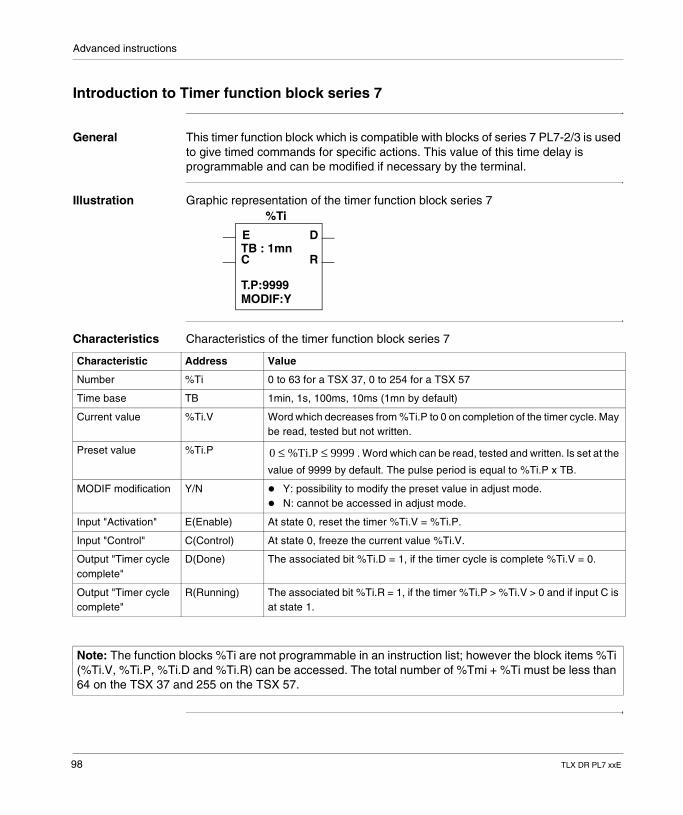
Advanced instructions
Introduction to Timer function block series 7
General This timer function block which is compatible with blocks of series 7 PL7-2/3 is used to give timed commands for specific actions. This value of this time delay is programmable and can be modified if necessary by the terminal.
Illustration Graphic representation of the timer function block series 7
Characteristics Characteristics of the timer function block series 7
%Ti
E
C
D
RTB : 1mn
T.P:9999MODIF:Y
Characteristic Address Value
Number %Ti 0 to 63 for a TSX 37, 0 to 254 for a TSX 57
Time base TB 1min, 1s, 100ms, 10ms (1mn by default)
Current value %Ti.V Word which decreases from %Ti.P to 0 on completion of the timer cycle. May be read, tested but not written.
Preset value %Ti.P . Word which can be read, tested and written. Is set at the
value of 9999 by default. The pulse period is equal to %Ti.P x TB.
MODIF modification Y/N � Y: possibility to modify the preset value in adjust mode.� N: cannot be accessed in adjust mode.
Input "Activation" E(Enable) At state 0, reset the timer %Ti.V = %Ti.P.
Input "Control" C(Control) At state 0, freeze the current value %Ti.V.
Output "Timer cycle complete"
D(Done) The associated bit %Ti.D = 1, if the timer cycle is complete %Ti.V = 0.
Output "Timer cycle complete"
R(Running) The associated bit %Ti.R = 1, if the timer %Ti.P > %Ti.V > 0 and if input C is at state 1.
0 %Ti.P 9999≤ ≤
Note: The function blocks %Ti are not programmable in an instruction list; however the block items %Ti (%Ti.V, %Ti.P, %Ti.D and %Ti.R) can be accessed. The total number of %Tmi + %Ti must be less than 64 on the TSX 37 and 255 on the TSX 57.
98 TLX DR PL7 xxE
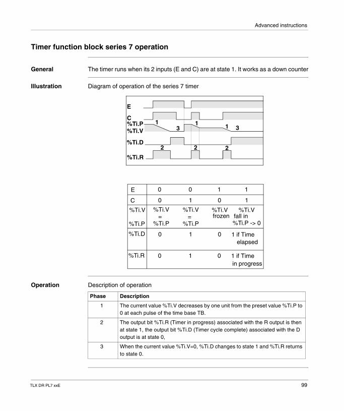
Advanced instructions
Timer function block series 7 operation
General The timer runs when its 2 inputs (E and C) are at state 1. It works as a down counter
Illustration Diagram of operation of the series 7 timer
Operation Description of operation
E
C%Ti.P%Ti.V
%Ti.R
%Ti.D
3 31 1 1
2 2 2
E
C
%Ti.D
%Ti.R
0 0 11
0 1 10
%Ti.V=
%Ti.P
%Ti.V
%Ti.P
%Ti.V=
%Ti.P
%Ti.Vfrozen
%Ti.Vfall in%Ti.P -> 0
0 1 1 if Time0
elapsed
0 1 1 if Time0in progress
Phase Description
1 The current value %Ti.V decreases by one unit from the preset value %Ti.P to 0 at each pulse of the time base TB.
2 The output bit %Ti.R (Timer in progress) associated with the R output is then at state 1, the output bit %Ti.D (Timer cycle complete) associated with the D output is at state 0,
3 When the current value %Ti.V=0, %Ti.D changes to state 1 and %Ti.R returns to state 0.
TLX DR PL7 xxE 99
Advanced instructions
Instructions In structured text language, 3 instructions are used to program the timer function blocks %Ti� PRESET %Ti: Resets the timer� START %Ti: Starts the timer cycle� STOP %Ti: Freezes the current value of the timer
100 TLX DR PL7 xxE
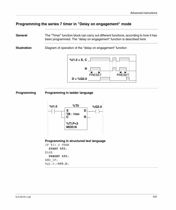
Advanced instructions
Programming the series 7 timer in "Delay on engagement" mode
General The "Timer" function block can carry out different functions, according to how it has been programmed. The "delay on engagement" function is described here
Illustration Diagram of operation of the "delay on engagement" function
Programming Programming in ladder language
Programming in structured text languageIF %I1.0 THEN START %T0;ELSE PRESET %T0;END_IF;%Q2.0:=%T0.D;
%I1.0 = E, C
R
D = %Q2.0PRESET PRESET
%T0
E
C
D
RTB : 1mn
%Ti.P=3MOD:N
%I1.0 %Q2.0
TLX DR PL7 xxE 101
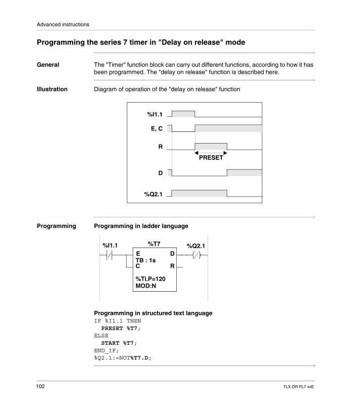
Advanced instructions
Programming the series 7 timer in "Delay on release" mode
General The "Timer" function block can carry out different functions, according to how it has been programmed. The "delay on release" function is described here.
Illustration Diagram of operation of the "delay on release" function
Programming Programming in ladder language
Programming in structured text languageIF %I1.1 THEN PRESET %T7;ELSE START %T7;END_IF;%Q2.1:=NOT%T7.D;
%I1.1
R
%Q2.1
PRESET
E, C
D
%T7
E
C
D
RTB : 1s
%Ti.P=120MOD:N
%I1.1 %Q2.1
102 TLX DR PL7 xxE
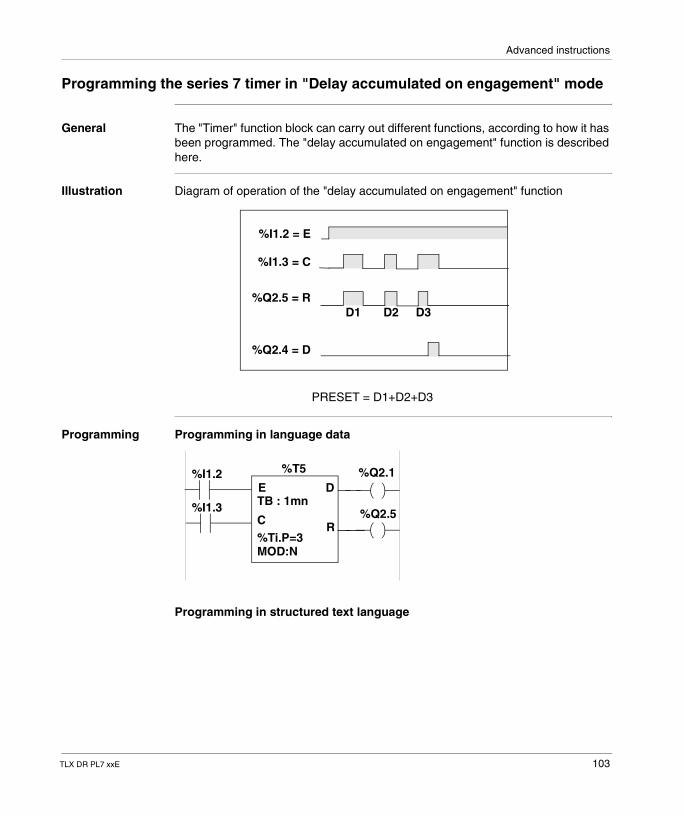
Advanced instructions
Programming the series 7 timer in "Delay accumulated on engagement" mode
General The "Timer" function block can carry out different functions, according to how it has been programmed. The "delay accumulated on engagement" function is described here.
Illustration Diagram of operation of the "delay accumulated on engagement" function
Programming Programming in language data
Programming in structured text language
%I1.2 = E
%Q2.5 = R
%I1.3 = C
%Q2.4 = D
D1 D2 D3
PRESET = D1+D2+D3
%T5
E
C
D
R
TB : 1mn
%Ti.P=3MOD:N
%I1.2 %Q2.1
%Q2.5%I1.3
TLX DR PL7 xxE 103
Advanced instructions
IF %I1.2 THENIF %I1.3 THEN START %T5;ELSE STOP %T5;END_IF;ELSE PRESET %T5;END_IF;%Q2.4:=%T5.D;%Q2.5:=%T5.R;
104 TLX DR PL7 xxE
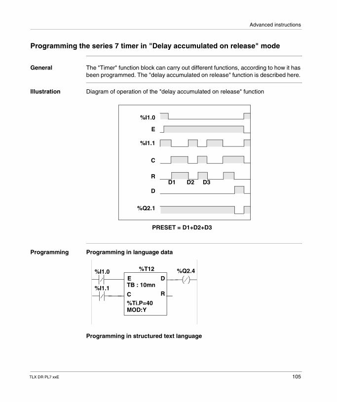
Advanced instructions
Programming the series 7 timer in "Delay accumulated on release" mode
General The "Timer" function block can carry out different functions, according to how it has been programmed. The "delay accumulated on release" function is described here.
Illustration Diagram of operation of the "delay accumulated on release" function
Programming Programming in language data
Programming in structured text language
%I1.0
%I1.1
E
%Q2.1
D1 D2 D3
C
D
R
PRESET = D1+D2+D3
%T12
E
C
D
RTB : 10mn
%Ti.P=40MOD:Y
%I1.0 %Q2.4
%I1.1
TLX DR PL7 xxE 105
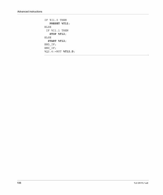
Advanced instructions
IF %I1.0 THEN PRESET %T12;ELSE IF %I1.1 THEN STOP %T12;ELSE START %T12;END_IF;END_IF;%Q2.4:=NOT %T12.D;
106 TLX DR PL7 xxE
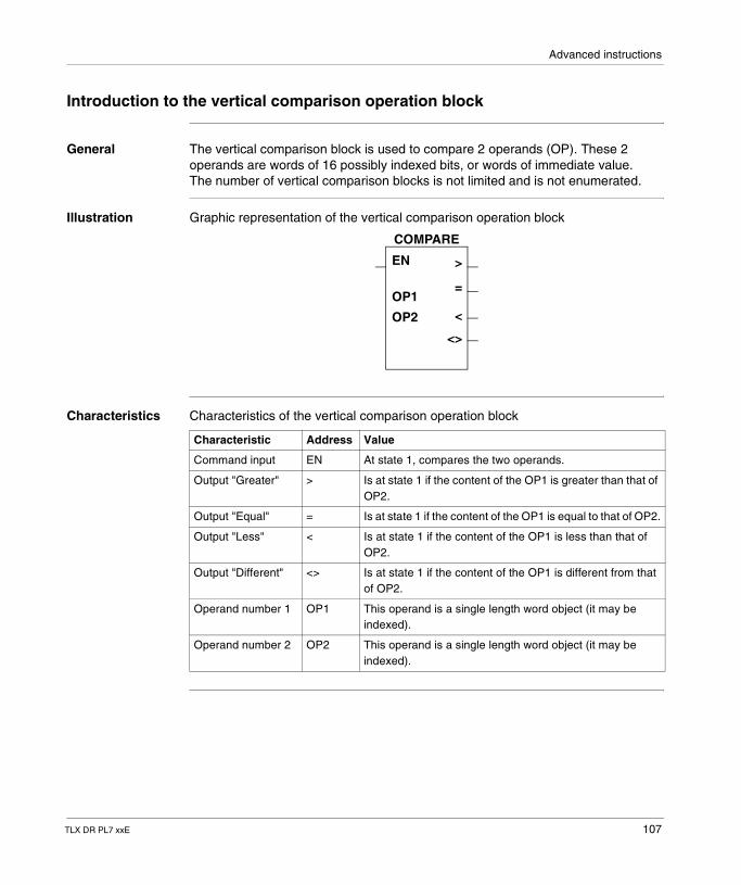
Advanced instructions
Introduction to the vertical comparison operation block
General The vertical comparison block is used to compare 2 operands (OP). These 2 operands are words of 16 possibly indexed bits, or words of immediate value.The number of vertical comparison blocks is not limited and is not enumerated.
Illustration Graphic representation of the vertical comparison operation block
Characteristics Characteristics of the vertical comparison operation block
>
=
<
<>
EN
OP1
OP2
COMPARE
Characteristic Address Value
Command input EN At state 1, compares the two operands.
Output "Greater" > Is at state 1 if the content of the OP1 is greater than that of OP2.
Output "Equal" = Is at state 1 if the content of the OP1 is equal to that of OP2.
Output "Less" < Is at state 1 if the content of the OP1 is less than that of OP2.
Output "Different" <> Is at state 1 if the content of the OP1 is different from that of OP2.
Operand number 1 OP1 This operand is a single length word object (it may be indexed).
Operand number 2 OP2 This operand is a single length word object (it may be indexed).
TLX DR PL7 xxE 107
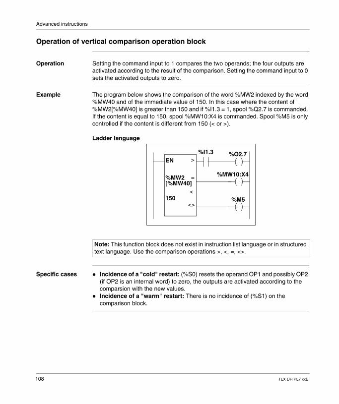
Advanced instructions
Operation of vertical comparison operation block
Operation Setting the command input to 1 compares the two operands; the four outputs are activated according to the result of the comparison. Setting the command input to 0 sets the activated outputs to zero.
Example The program below shows the comparison of the word %MW2 indexed by the word %MW40 and of the immediate value of 150. In this case where the content of %MW2[%MW40] is greater than 150 and if %I1.3 = 1, spool %Q2.7 is commanded. If the content is equal to 150, spool %MW10:X4 is commanded. Spool %M5 is only controlled if the content is different from 150 (< or >).
Ladder language
Specific cases � Incidence of a "cold" restart: (%S0) resets the operand OP1 and possibly OP2 (if OP2 is an internal word) to zero, the outputs are activated according to the comparsion with the new values.
� Incidence of a "warm" restart: There is no incidence of (%S1) on the comparison block.
Note: This function block does not exist in instruction list language or in structured text language. Use the comparison operations >, <, =, <>.
EN%I1.3
>
=
<
<>
%Q2.7
%MW10:X4
%M5
%MW2[%MW40]
150
108 TLX DR PL7 xxE
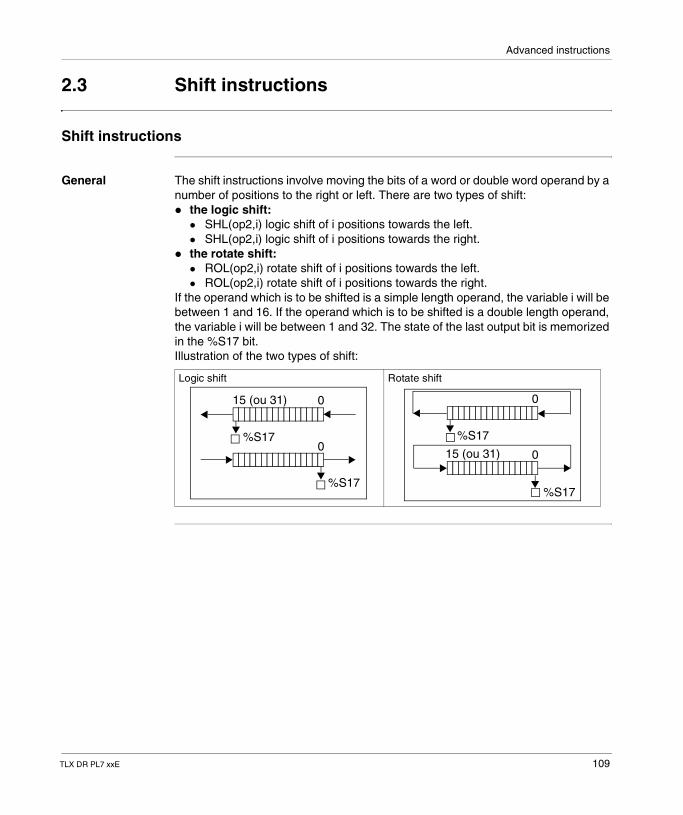
Advanced instructions
2.3 Shift instructions
Shift instructions
General The shift instructions involve moving the bits of a word or double word operand by a number of positions to the right or left. There are two types of shift:� the logic shift:
� SHL(op2,i) logic shift of i positions towards the left.� SHL(op2,i) logic shift of i positions towards the right.
� the rotate shift:� ROL(op2,i) rotate shift of i positions towards the left.� ROL(op2,i) rotate shift of i positions towards the right.
If the operand which is to be shifted is a simple length operand, the variable i will be between 1 and 16. If the operand which is to be shifted is a double length operand, the variable i will be between 1 and 32. The state of the last output bit is memorized in the %S17 bit.Illustration of the two types of shift:
Logic shift Rotate shift
%S17
15 (ou 31)
0
0
%S17
%S17
0
0
%S17
15 (ou 31)
TLX DR PL7 xxE 109
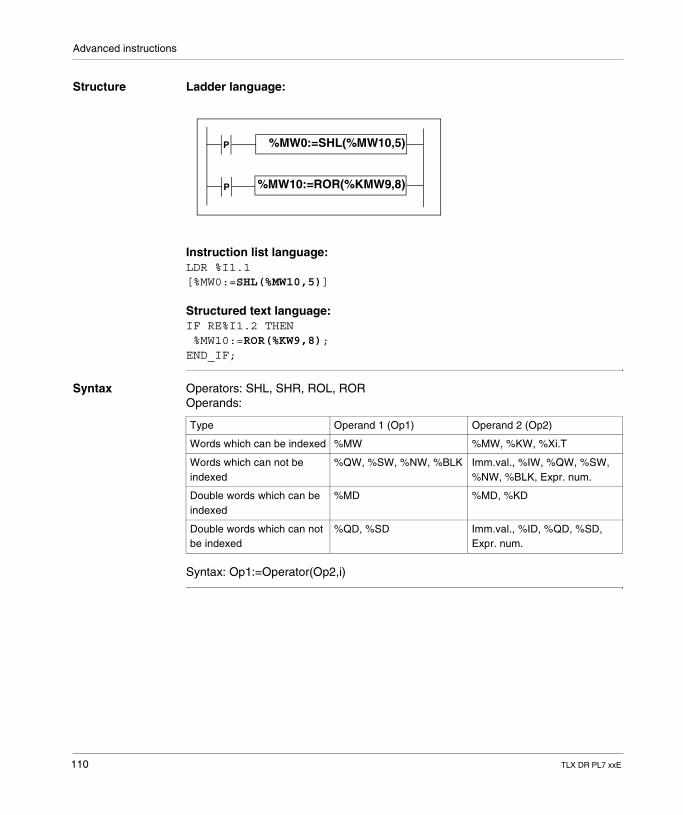
Advanced instructions
Structure Ladder language:
Instruction list language:LDR %I1.1[%MW0:=SHL(%MW10,5)]
Structured text language:IF RE%I1.2 THEN %MW10:=ROR(%KW9,8);END_IF;
Syntax Operators: SHL, SHR, ROL, ROROperands:
Syntax: Op1:=Operator(Op2,i)
%MW0:=SHL(%MW10,5)
%MW10:=ROR(%KMW9,8)
P
P
Type Operand 1 (Op1) Operand 2 (Op2)
Words which can be indexed %MW %MW, %KW, %Xi.T
Words which can not be indexed
%QW, %SW, %NW, %BLK Imm.val., %IW, %QW, %SW, %NW, %BLK, Expr. num.
Double words which can be indexed
%MD %MD, %KD
Double words which can not be indexed
%QD, %SD Imm.val., %ID, %QD, %SD, Expr. num.
110 TLX DR PL7 xxE
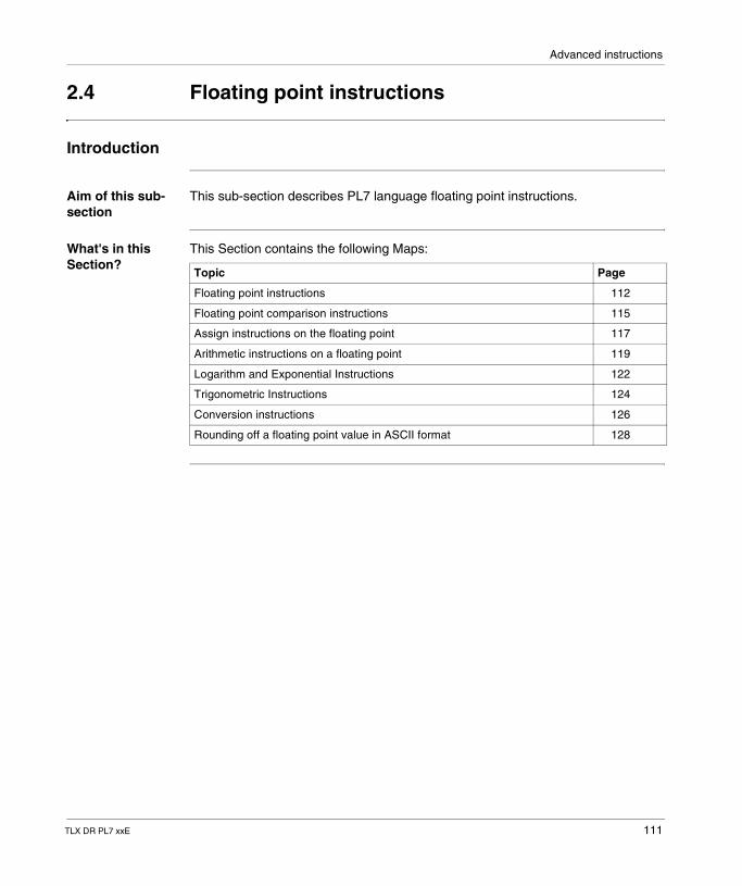
Advanced instructions
2.4 Floating point instructions
Introduction
Aim of this sub-section
This sub-section describes PL7 language floating point instructions.
What's in this Section?
This Section contains the following Maps:
Topic Page
Floating point instructions 112
Floating point comparison instructions 115
Assign instructions on the floating point 117
Arithmetic instructions on a floating point 119
Logarithm and Exponential Instructions 122
Trigonometric Instructions 124
Conversion instructions 126
Rounding off a floating point value in ASCII format 128
TLX DR PL7 xxE 111
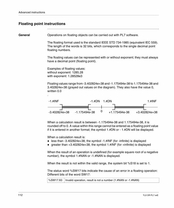
Advanced instructions
Floating point instructions
General Operations on floating objects can be carried out with PL7 software.
The floating format used is the standard IEEE STD 734-1985 (equivalent IEC 559). The length of the words is 32 bits, which corresponds to the single decimal point floating numbers.
The floating values can be represented with or without exponent; they must always have a decimal point (floating point).
Examples of floating values: without exponent: 1285.28 with exponent: 1.28528e3
Floating values range from -3.402824e+38 and -1.175494e-38 to 1.175494e-38 and 3.402824e+38 (grayed out values on the diagram). They also have the value 0, written 0.0.
When a calculation result is between -1.175494e-38 and 1.175494e-38, it is rounded off to 0. A value within this range cannot be entered as a floating point value if it is entered in another format; the symbol 1.#DN or - 1.#DN will be displayed.
When a calculation result is: � less than -3.402824e+38, the symbol -1.#INF (for -infinite) is displayed� greater than +3.402824e+38, the symbol 1.#INF (for +infinite) is displayed
When the result of an operation is undefined (for example square root of a negative number), the symbol 1.#NAN or -1.#NAN is displayed.
When the result is not within the valid range, the system bit %S18 is set to 1.
The status word %SW17 bits indicate the cause of an error in a floating operation:Different bits of the word SW17:
%SW17:X0 Invalid operation, result is not a number (1.#NAN or -1.#NAN)
-1.#INF -1.#DN 1.#DN 1.#INF
-3.402824e+38 -1.175494e-38 +1.175494e-38 +3.402824e+380
112 TLX DR PL7 xxE
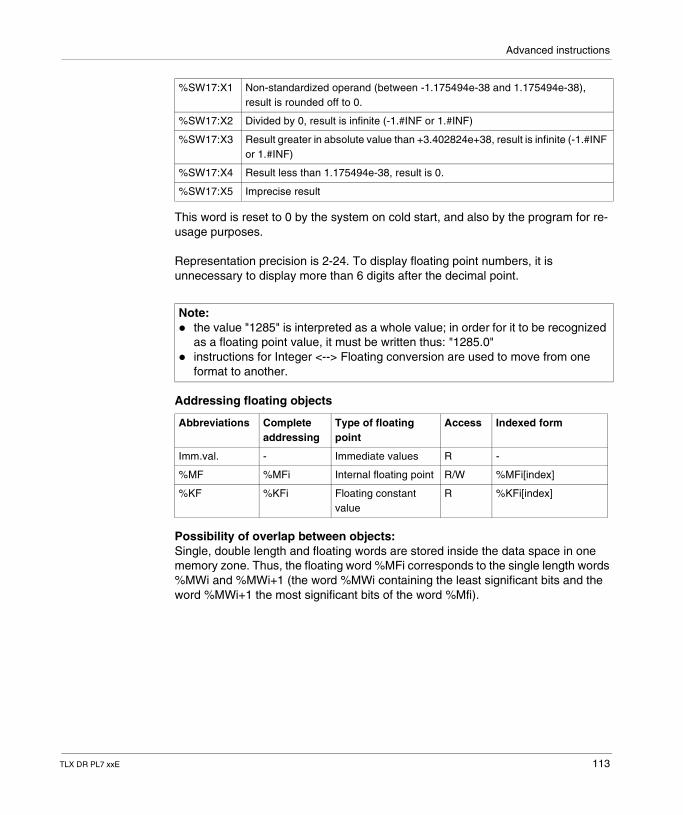
Advanced instructions
This word is reset to 0 by the system on cold start, and also by the program for re-usage purposes.
Representation precision is 2-24. To display floating point numbers, it is unnecessary to display more than 6 digits after the decimal point.
Addressing floating objects
Possibility of overlap between objects:Single, double length and floating words are stored inside the data space in one memory zone. Thus, the floating word %MFi corresponds to the single length words %MWi and %MWi+1 (the word %MWi containing the least significant bits and the word %MWi+1 the most significant bits of the word %Mfi).
%SW17:X1 Non-standardized operand (between -1.175494e-38 and 1.175494e-38), result is rounded off to 0.
%SW17:X2 Divided by 0, result is infinite (-1.#INF or 1.#INF)
%SW17:X3 Result greater in absolute value than +3.402824e+38, result is infinite (-1.#INF or 1.#INF)
%SW17:X4 Result less than 1.175494e-38, result is 0.
%SW17:X5 Imprecise result
Note: � the value "1285" is interpreted as a whole value; in order for it to be recognized
as a floating point value, it must be written thus: "1285.0"� instructions for Integer <--> Floating conversion are used to move from one
format to another.
Abbreviations Complete addressing
Type of floating point
Access Indexed form
Imm.val. - Immediate values R -
%MF %MFi Internal floating point R/W %MFi[index]
%KF %KFi Floating constant value
R %KFi[index]
TLX DR PL7 xxE 113
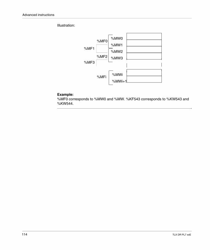
Advanced instructions
Illustration:
Example: %MF0 corresponds to %MW0 and %MW. %KF543 corresponds to %KW543 and %KW544.
%MW0
%MW1
%MW2
%MW3
%MWi
%MWi+1
%MF0
%MF1
%MF2
%MF3
%MFi
114 TLX DR PL7 xxE
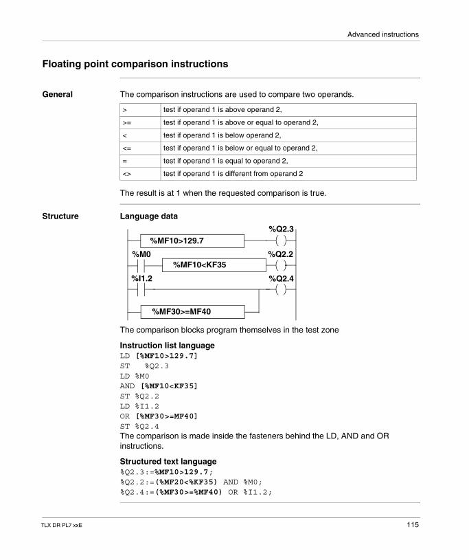
Advanced instructions
Floating point comparison instructions
General The comparison instructions are used to compare two operands.
The result is at 1 when the requested comparison is true.
Structure Language data
The comparison blocks program themselves in the test zone
Instruction list languageLD [%MF10>129.7]ST %Q2.3LD %M0AND [%MF10<KF35]ST %Q2.2LD %I1.2OR [%MF30>=MF40]ST %Q2.4The comparison is made inside the fasteners behind the LD, AND and OR instructions.
Structured text language%Q2.3:=%MF10>129.7;%Q2.2:=(%MF20<%KF35) AND %M0;%Q2.4:=(%MF30>=%MF40) OR %I1.2;
> test if operand 1 is above operand 2,
>= test if operand 1 is above or equal to operand 2,
< test if operand 1 is below operand 2,
<= test if operand 1 is below or equal to operand 2,
= test if operand 1 is equal to operand 2,
<> test if operand 1 is different from operand 2
%MF10>129.7
%MF10<KF35
%MF30>=MF40
%Q2.3
%Q2.2
%Q2.4
%M0
%I1.2
TLX DR PL7 xxE 115
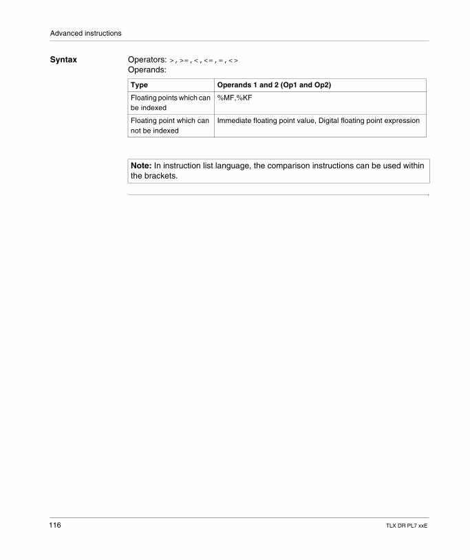
Advanced instructions
Syntax Operators: >,>=,<,<=,=,<>Operands:
Type Operands 1 and 2 (Op1 and Op2)
Floating points which can be indexed
%MF,%KF
Floating point which can not be indexed
Immediate floating point value, Digital floating point expression
Note: In instruction list language, the comparison instructions can be used within the brackets.
116 TLX DR PL7 xxE
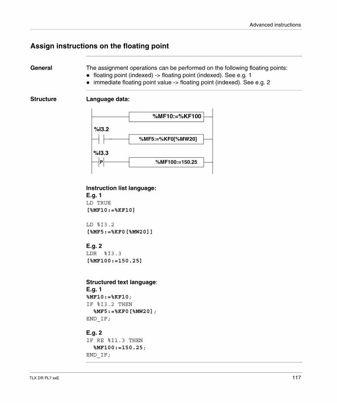
Advanced instructions
Assign instructions on the floating point
General The assignment operations can be performed on the following floating points:� floating point (indexed) -> floating point (indexed). See e.g. 1� immediate floating point value -> floating point (indexed). See e.g. 2
Structure Language data:
Instruction list language: E.g. 1LD TRUE[%MF10:=%KF10]
LD %I3.2[%MF5:=%KF0[%MW20]]
E.g. 2LDR %I3.3[%MF100:=150.25]
Structured text language:E.g. 1%MF10:=%KF10;IF %I3.2 THEN %MF5:=%KF0[%MW20];END_IF;
E.g. 2IF RE %I1.3 THEN %MF100:=150.25;END_IF;
%MF10:=%KF100
%MF5:=%KF0[%MW20]
%MF100:=150.25P
%I3.2
%I3.3
TLX DR PL7 xxE 117
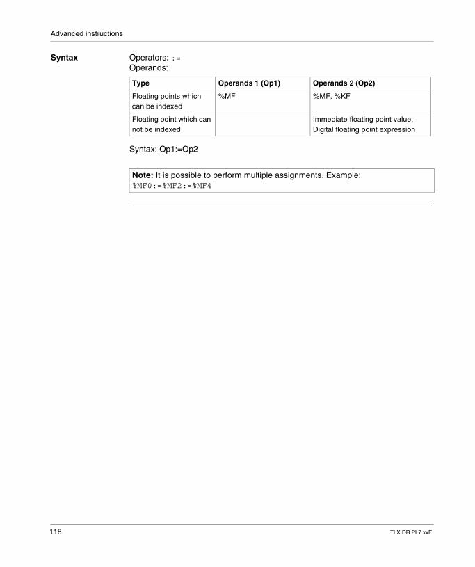
Advanced instructions
Syntax Operators: :=Operands:
Syntax: Op1:=Op2
Type Operands 1 (Op1) Operands 2 (Op2)
Floating points which can be indexed
%MF %MF, %KF
Floating point which can not be indexed
Immediate floating point value, Digital floating point expression
Note: It is possible to perform multiple assignments. Example: %MF0:=%MF2:=%MF4
118 TLX DR PL7 xxE
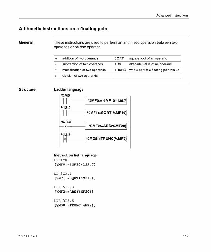
Advanced instructions
Arithmetic instructions on a floating point
General These instructions are used to perform an arithmetic operation between two operands or on one operand.
Structure Ladder language
Instruction list languageLD %M0[%MF0:=%MF10+129.7]
LD %I3.2[%MF1:=SQRT(%MF10)]
LDR %I3.3[%MF2:=ABS(%MF20)]
LDR %I3.5[%MD8:=TRUNC(%MF2)]
+ addition of two operands SQRT square root of an operand
- subtraction of two operands ABS absolute value of an operand
* multiplication of two operands TRUNC whole part of a floating point value
/ division of two operands
P
P
%M0
%I3.2
%I3.3
%I3.5
%MF0:=%MF10+129.7
%MF1:=SQRT(%MF10)
%MF2:=ABS(%MF20)
%MD8:=TRUNC(%MF2)
TLX DR PL7 xxE 119
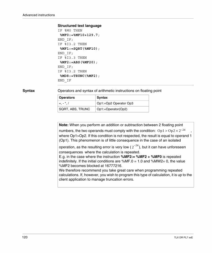
Advanced instructions
Structured text languageIF %M0 THEN %MF0:=%MF10+129.7;END_IF;IF %I3.2 THEN %MF1:=SQRT(%MF10);END_IF;IF %I3.3 THEN %MF2:=ABS(%MF20);END_IF;IF %I3.2 THEN %MD8:=TRUNC(%MF2);END_IF
Syntax Operators and syntax of arithmetic instructions on floating point
Operators Syntax
+, - *, / Op1:=Op2 Operator Op3
SQRT, ABS, TRUNC Op1:=Operator(Op2)
Note: When you perform an addition or subtraction between 2 floating point
numbers, the two operands must comply with the condition: , where Op1>Op2. If this condition is not respected, the result is equal to operand 1 (Op1). This phenomenon is of little consequence in the case of an isolated
operation, as the resulting error is very low ( ), but it can have unforeseen consequences where the calculation is repeated. E.g. in the case where the instruction %MF2:= %MF2 + %MF0 is repeated indefinitely. If the initial conditions are %MF.0 = 1.0 and %MW2= 0, the value %MF2 becomes blocked at 16777216.We therefore recommend you take great care when programming repeated calculations. If, however, you wish to program this type of calculation, it is up to the client application to manage truncation errors.
Op1 Op2 2 24–×>
224–
120 TLX DR PL7 xxE
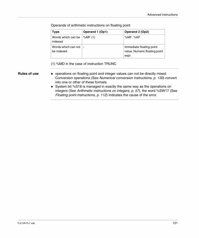
Advanced instructions
Operands of arithmetic instructions on floating point
(1) %MD in the case of instruction TRUNC
Rules of use � operations on floating point and integer values can not be directly mixed. Conversion operations (See Numerical conversion instructions, p. 130) convert into one or other of these formats.
� System bit %S18 is managed in exactly the same way as the operations on integers (See Arithmetic instructions on integers, p. 57), the word %SW17 (See Floating point instructions, p. 112) indicates the cause of the error.
Type Operand 1 (Op1) Operand 2 (Op2)
Words which can be indexed
%MF (1) %MF, %KF
Words which can not be indexed
- Immediate floating point value, Numeric floating point expr.
TLX DR PL7 xxE 121
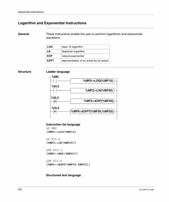
Advanced instructions
Logarithm and Exponential Instructions
General These instructions enable the user to perform logarithmic and exponential operations.
Structure Ladder language
Instruction list languageLD %M0[%MF0:=LOG(%MF10]
LD %I3.2[%MF2:=LN(%MF20)]
LDR %I3.3[%MF4:=EXP(%MF40)]
LDR %I3.4[%MF6:=EXPT(%MF50,%MF52)]
Structured text language
LOG base 10 logarithm
LN Napierian logarithm
EXP natural exponential
EXPT exponentiation of an actual by an actual
%MF6:=EXPT(%MF50,%MF52)
P
P
%M0
%I3.2
%I3.3
%I3.4
%MF0:=LOG(%MF10)
%MF2:=LN(%MF20)
%MF4:=EXP(%MF40)
122 TLX DR PL7 xxE
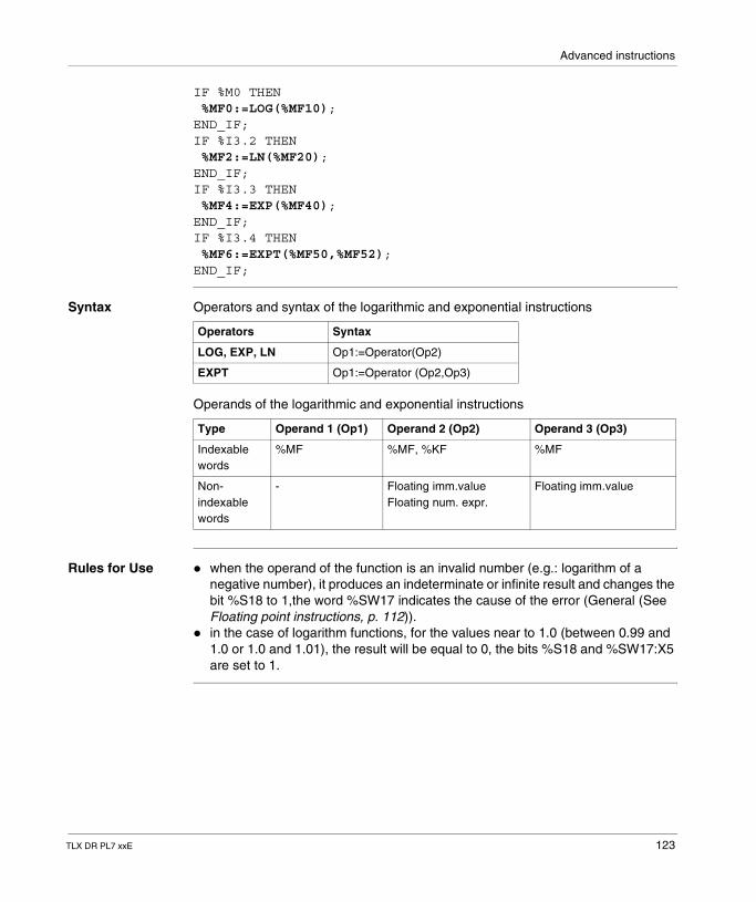
Advanced instructions
IF %M0 THEN %MF0:=LOG(%MF10);END_IF;IF %I3.2 THEN %MF2:=LN(%MF20);END_IF;IF %I3.3 THEN %MF4:=EXP(%MF40);END_IF;IF %I3.4 THEN %MF6:=EXPT(%MF50,%MF52);END_IF;
Syntax Operators and syntax of the logarithmic and exponential instructions
Operands of the logarithmic and exponential instructions
Rules for Use � when the operand of the function is an invalid number (e.g.: logarithm of a negative number), it produces an indeterminate or infinite result and changes the bit %S18 to 1,the word %SW17 indicates the cause of the error (General (See Floating point instructions, p. 112)).
� in the case of logarithm functions, for the values near to 1.0 (between 0.99 and 1.0 or 1.0 and 1.01), the result will be equal to 0, the bits %S18 and %SW17:X5 are set to 1.
Operators Syntax
LOG, EXP, LN Op1:=Operator(Op2)
EXPT Op1:=Operator (Op2,Op3)
Type Operand 1 (Op1) Operand 2 (Op2) Operand 3 (Op3)
Indexable words
%MF %MF, %KF %MF
Non-indexable words
- Floating imm.valueFloating num. expr.
Floating imm.value
TLX DR PL7 xxE 123
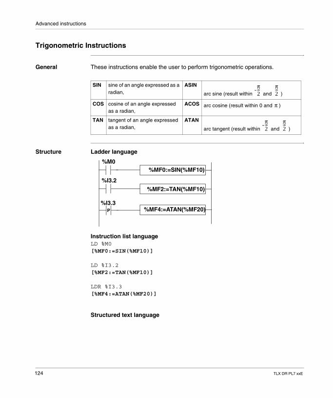
Advanced instructions
Trigonometric Instructions
General These instructions enable the user to perform trigonometric operations.
Structure Ladder language
Instruction list languageLD %M0[%MF0:=SIN(%MF10)]
LD %I3.2[%MF2:=TAN(%MF10)]
LDR %I3.3[%MF4:=ATAN(%MF20)]
Structured text language
SIN sine of an angle expressed as a radian,
ASIN
arc sine (result within and )
COS cosine of an angle expressed as a radian,
ACOS arc cosine (result within 0 and )
TAN tangent of an angle expressed as a radian,
ATAN
arc tangent (result within and )
-π2--- π
2---
π
-π2--- π
2---
P
%M0
%I3.2
%I3.3
%MF0:=SIN(%MF10)
%MF2:=TAN(%MF10)
%MF4:=ATAN(%MF20)
124 TLX DR PL7 xxE
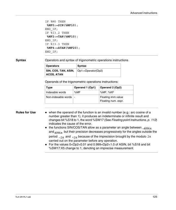
Advanced instructions
IF %M0 THEN %MF0:=SIN(%MF10);END_IF;IF %I3.2 THEN %MF2:=TAN(%MF10);END_IF;IF %I3.3 THEN %MF4:=ATAN(%MF20);END_IF;
Syntax Operators and syntax of trigonometric operations instructions
Operands of the trigonometric operations instructions:
Rules for Use � when the operand of the function is an invalid number (e.g.: arc cosine of a number greater than 1), it produces an indeterminate or infinite result and changes bit %S18 to 1, the word %SW17 (See Floating point instructions, p. 112) indicates the cause of the error.
� the functions SIN/COS/TAN allow as a parameter an angle between and but their precision decreases progressively for the angles outside the
period and because of the imprecision brought by the modulo carried out on the parameter before any operation.
� For the values 0<Op2<0.01 and 0.999<Op2<1.0 of ASIN, bit %S18 and bit %SW17:X5 change to 1, denoting an imprecise measurement.
Operators Syntax
SIN, COS, TAN, ASIN, ACOS, ATAN
Op1:=Operator(Op2)
Type Operand 1 (Op1) Operand 2 (Op2)
Indexable words %MF %MF, %KF
Non-indexable words - Floating imm.valueFloating num. expr.
4096π–
4096π2– π +2π 2π
TLX DR PL7 xxE 125
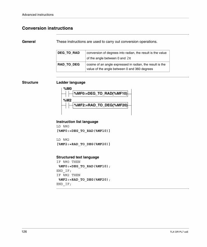
Advanced instructions
Conversion instructions
General These instructions are used to carry out conversion operations.
Structure Ladder language
Instruction list languageLD %M0[%MF0:=DEG_TO_RAD(%MF10)]
LD %M2[%MF2:=RAD_TO_DEG(%MF20)]
Structured text languageIF %M0 THEN %MF0:=DEG_TO_RAD(%MF10);END_IF;IF %M2 THEN %MF2:=RAD_TO_DEG(%MF20);END_IF;
DEG_TO_RAD conversion of degrees into radian, the result is the value
of the angle between 0 and
RAD_TO_DEG cosine of an angle expressed in radian, the result is the value of the angle between 0 and 360 degrees
2π
%M0
%M2%MF2:=RAD_TO_DEG(%MF20)
%MF0:=DEG_TO_RAD(%MF10)
126 TLX DR PL7 xxE
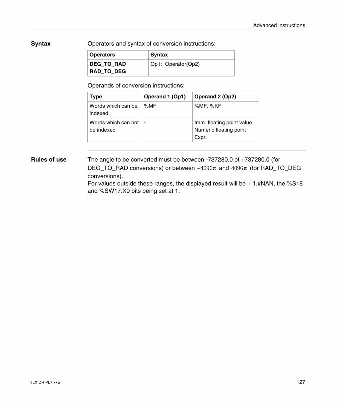
Advanced instructions
Syntax Operators and syntax of conversion instructions:
Operands of conversion instructions:
Rules of use The angle to be converted must be between -737280.0 et +737280.0 (for DEG_TO_RAD conversions) or between and (for RAD_TO_DEG conversions). For values outside these ranges, the displayed result will be + 1.#NAN, the %S18 and %SW17:X0 bits being set at 1.
Operators Syntax
DEG_TO_RAD RAD_TO_DEG
Op1:=Operator(Op2)
Type Operand 1 (Op1) Operand 2 (Op2)
Words which can be indexed
%MF %MF, %KF
Words which can not be indexed
- Imm. floating point valueNumeric floating point Expr.
4096π– 4096π
TLX DR PL7 xxE 127
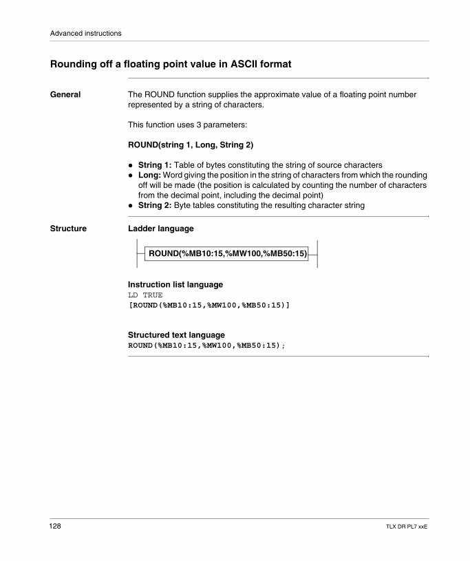
Advanced instructions
Rounding off a floating point value in ASCII format
General The ROUND function supplies the approximate value of a floating point number represented by a string of characters.
This function uses 3 parameters:
ROUND(string 1, Long, String 2)
� String 1: Table of bytes constituting the string of source characters� Long: Word giving the position in the string of characters from which the rounding
off will be made (the position is calculated by counting the number of characters from the decimal point, including the decimal point)
� String 2: Byte tables constituting the resulting character string
Structure Ladder language
Instruction list languageLD TRUE[ROUND(%MB10:15,%MW100,%MB50:15)]
Structured text languageROUND(%MB10:15,%MW100,%MB50:15);
ROUND(%MB10:15,%MW100,%MB50:15)
128 TLX DR PL7 xxE
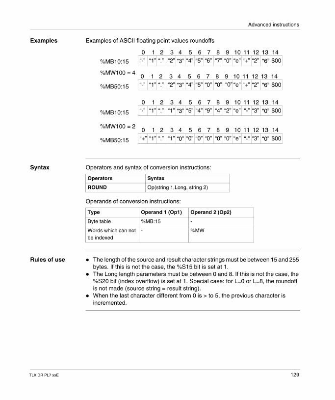
Advanced instructions
Examples Examples of ASCII floating point values roundoffs
Syntax Operators and syntax of conversion instructions:
Operands of conversion instructions:
Rules of use � The length of the source and result character strings must be between 15 and 255 bytes. If this is not the case, the %S15 bit is set at 1.
� The Long length parameters must be between 0 and 8. If this is not the case, the %S20 bit (index overflow) is set at 1. Special case: for L=0 or L=8, the roundoff is not made (source string = result string).
� When the last character different from 0 is > to 5, the previous character is incremented.
“-” “1” “.” “2” “3” “4” “5” “6” “7” “0” “e” “+” “2” “6” $00
“-” “1” “.” “2” “3” “4” “5” “0” “0” “e” “+” “2” “6” $00
“-” “1” “.” “1” “3” “5” “4” “9” “4” “2” “e” “-” “3” “0” $00
“+” “1” “.” “1” “0” “0” “0” “0” “0” “0” “e” “-” “3” “0” $00
“0”
0 1 2 3 4 5 6 7 8 9 10 11 12 13 14
0 1 2 3 4 5 6 7 8 9 10 11 12 13 14
0 1 2 3 4 5 6 7 8 9 10 11 12 13 14
0 1 2 3 4 5 6 7 8 9 10 11 12 13 14
%MB10:15
%MW100 = 4
%MB50:15
%MB10:15
%MW100 = 2
%MB50:15
Operators Syntax
ROUND Op(string 1,Long, string 2)
Type Operand 1 (Op1) Operand 2 (Op2)
Byte table %MB:15 -
Words which can not be indexed
- %MW
TLX DR PL7 xxE 129
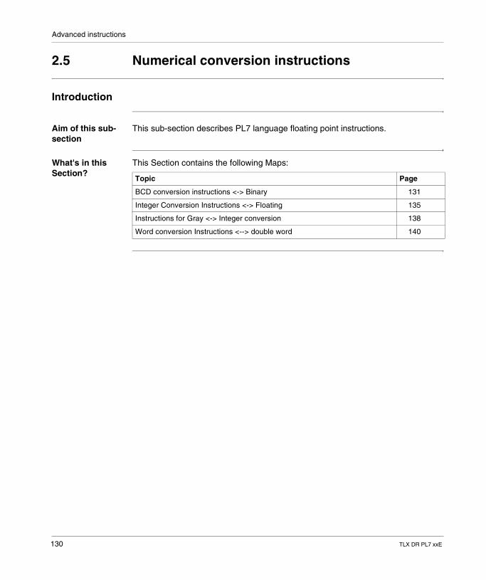
Advanced instructions
2.5 Numerical conversion instructions
Introduction
Aim of this sub-section
This sub-section describes PL7 language floating point instructions.
What's in this Section?
This Section contains the following Maps:
Topic Page
BCD conversion instructions <-> Binary 131
Integer Conversion Instructions <-> Floating 135
Instructions for Gray <-> Integer conversion 138
Word conversion Instructions <--> double word 140
130 TLX DR PL7 xxE
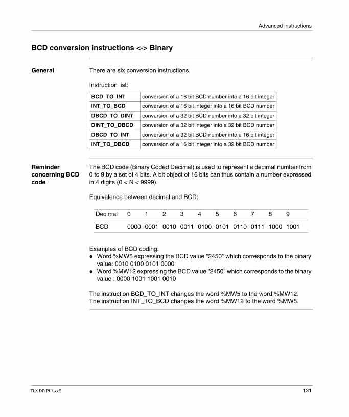
Advanced instructions
BCD conversion instructions <-> Binary
General There are six conversion instructions.
Instruction list:
Reminder concerning BCD code
The BCD code (Binary Coded Decimal) is used to represent a decimal number from 0 to 9 by a set of 4 bits. A bit object of 16 bits can thus contain a number expressed in 4 digits (0 < N < 9999).
Equivalence between decimal and BCD:
Examples of BCD coding:� Word %MW5 expressing the BCD value "2450" which corresponds to the binary
value: 0010 0100 0101 0000� Word %MW12 expressing the BCD value "2450" which corresponds to the binary
value : 0000 1001 1001 0010
The instruction BCD_TO_INT changes the word %MW5 to the word %MW12.The instruction INT_TO_BCD changes the word %MW12 to the word %MW5.
BCD_TO_INT conversion of a 16 bit BCD number into a 16 bit integer
INT_TO_BCD conversion of a 16 bit integer into a 16 bit BCD number
DBCD_TO_DINT conversion of a 32 bit BCD number into a 32 bit integer
DINT_TO_DBCD conversion of a 32 bit integer into a 32 bit BCD number
DBCD_TO_INT conversion of a 32 bit BCD number into a 16 bit integer
INT_TO_DBCD conversion of a 16 bit integer into a 32 bit BCD number
Decimal 0 1 2 3 4 5 6 7 8 9
BCD 0000 0001 0010 0011 0100 0101 0110 0111 1000 1001
TLX DR PL7 xxE 131
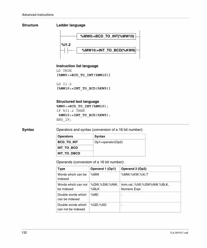
Advanced instructions
Structure Ladder language
Instruction list languageLD TRUE[%MW0:=BCD_TO_INT(%MW10)]
LD I1.2[%MW10:=INT_TO_BCD(%KW9)]
Structured text language%MW0:=BCD_TO_INT(%MW10);IF %I1.2 THEN %MW10:=INT_TO_BCD(%KW9);END_IF;
Syntax Operators and syntax (conversion of a 16 bit number):
Operands (conversion of a 16 bit number):
%MW0:=BCD_TO_INT(%MW10)
%MW10:=INT_TO_BCD(%KW9)
%I1.2
Operators Syntax
BCD_TO_INT Op1=operator(Op2)
INT_TO_BCD
INT_TO_DBCD
Type Operand 1 (Op1) Operand 2 (Op2)
Words which can be indexed
%MW %MW,%KW,%Xi.T
Words which can not be indexed
%QW,%SW,%NW,%BLK
Imm.val.,%IW,%SW%NW,%BLK, Numeric Expr.
Double words which can be indexed
%MD -
Double words which can not be indexed
%QD,%SD -
132 TLX DR PL7 xxE
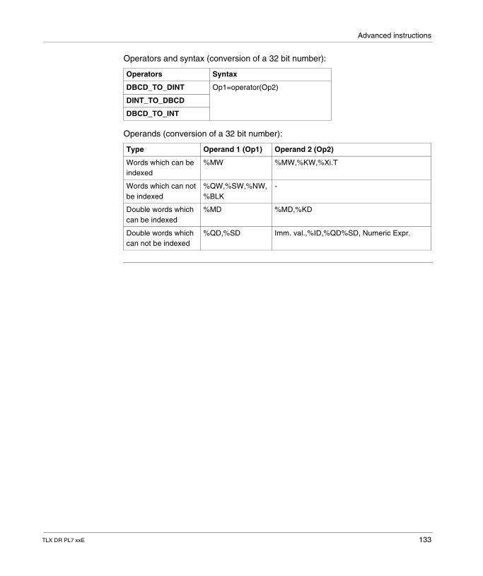
Advanced instructions
Operators and syntax (conversion of a 32 bit number):
Operands (conversion of a 32 bit number):
Operators Syntax
DBCD_TO_DINT Op1=operator(Op2)
DINT_TO_DBCD
DBCD_TO_INT
Type Operand 1 (Op1) Operand 2 (Op2)
Words which can be indexed
%MW %MW,%KW,%Xi.T
Words which can not be indexed
%QW,%SW,%NW,%BLK
-
Double words which can be indexed
%MD %MD,%KD
Double words which can not be indexed
%QD,%SD Imm. val.,%ID,%QD%SD, Numeric Expr.
TLX DR PL7 xxE 133
Advanced instructions
Example of applications
The BCD_TO_INT instruction is used to process a setpoint value present in PLC input on BCD encoded encoder wheels.The INT_TO_BCD instruction is used to display digital values (eg: calculation result, current value of function block) on BCD coded displays.
Rules of use � BCD->Binary conversionThe BCD-->Binary conversion instructions ensure that the conversion operator is working on a BCD coded value. If the value is not a BCD value, the %S18 system bit is set at 1 and the result returns the value of the first nibble which is at fault.E.g.: BCD_TO_INT(%MW2) with %MW2=4660 gives 1234 as the result. However, %MW2=242 (16#00F2) causes %S18 to set at 1 and the result is 15.For the DBCD_TO_INT instruction, if the BCD number is greater than 32767, the system bit %S18 is set at 1 and the value -1 is stored in the result.
� Binary->BCD conversionWhen the last character different from 0 is > at 5, the previous character is incremented.The instruction INT_TO_BCD (or DINT_TO_BCD) ensures that the conversion operator is working on a value between 0 and 9999 (or 0 and 9999 9999). If this is not the case, the system bit %S18 is set at 1 and the result returns the input parameter value.E.g.: INT_TO_BCD (%MW2) with %MW2=2478 gives 9336 as the result. However, %MW2=10004 causes %S18 to set at 1 and the result is 10004.For the INT_TO_DBCD instruction, if the input parameter is negative, the system bit %S18 is set at 1 and the result returns the input parameter value.
134 TLX DR PL7 xxE
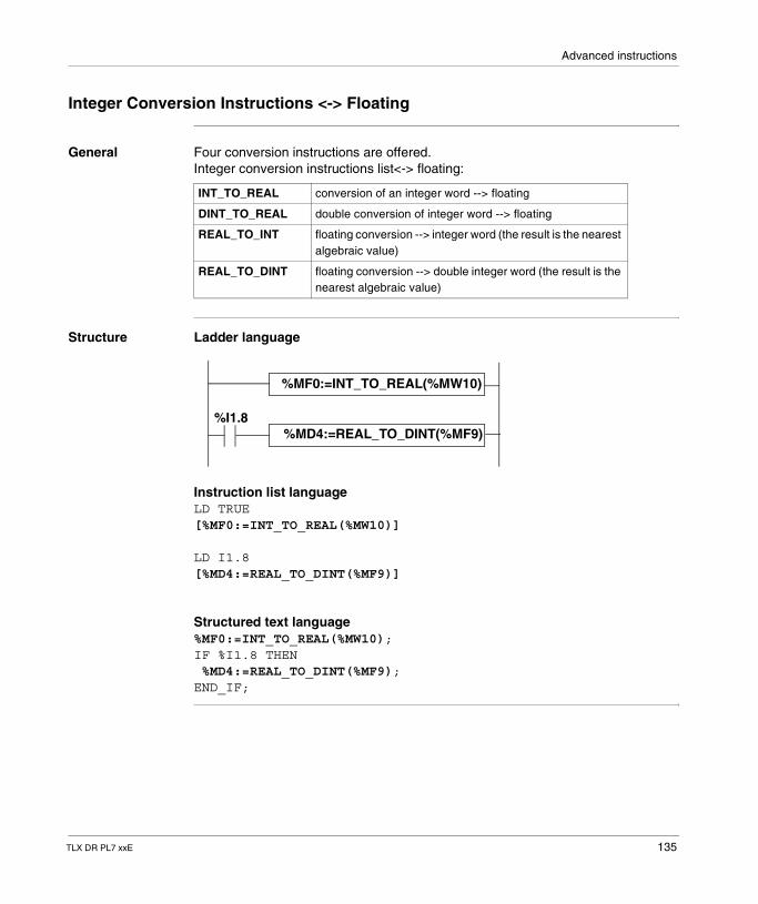
Advanced instructions
Integer Conversion Instructions <-> Floating
General Four conversion instructions are offered.Integer conversion instructions list<-> floating:
Structure Ladder language
Instruction list languageLD TRUE[%MF0:=INT_TO_REAL(%MW10)]
LD I1.8[%MD4:=REAL_TO_DINT(%MF9)]
Structured text language%MF0:=INT_TO_REAL(%MW10);IF %I1.8 THEN %MD4:=REAL_TO_DINT(%MF9);END_IF;
INT_TO_REAL conversion of an integer word --> floating
DINT_TO_REAL double conversion of integer word --> floating
REAL_TO_INT floating conversion --> integer word (the result is the nearest algebraic value)
REAL_TO_DINT floating conversion --> double integer word (the result is the nearest algebraic value)
%MF0:=INT_TO_REAL(%MW10)
%MD4:=REAL_TO_DINT(%MF9)%I1.8
TLX DR PL7 xxE 135
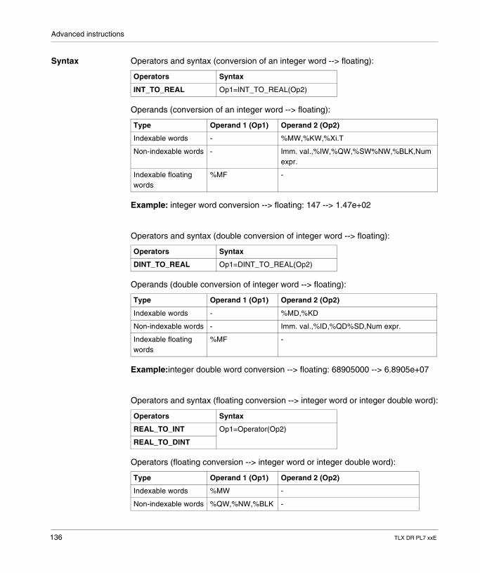
Advanced instructions
Syntax Operators and syntax (conversion of an integer word --> floating):
Operands (conversion of an integer word --> floating):
Example: integer word conversion --> floating: 147 --> 1.47e+02
Operators and syntax (double conversion of integer word --> floating):
Operands (double conversion of integer word --> floating):
Example:integer double word conversion --> floating: 68905000 --> 6.8905e+07
Operators and syntax (floating conversion --> integer word or integer double word):
Operators (floating conversion --> integer word or integer double word):
Operators Syntax
INT_TO_REAL Op1=INT_TO_REAL(Op2)
Type Operand 1 (Op1) Operand 2 (Op2)
Indexable words - %MW,%KW,%Xi.T
Non-indexable words - Imm. val.,%IW,%QW,%SW%NW,%BLK,Num expr.
Indexable floating words
%MF -
Operators Syntax
DINT_TO_REAL Op1=DINT_TO_REAL(Op2)
Type Operand 1 (Op1) Operand 2 (Op2)
Indexable words - %MD,%KD
Non-indexable words - Imm. val.,%ID,%QD%SD,Num expr.
Indexable floating words
%MF -
Operators Syntax
REAL_TO_INT Op1=Operator(Op2)
REAL_TO_DINT
Type Operand 1 (Op1) Operand 2 (Op2)
Indexable words %MW -
Non-indexable words %QW,%NW,%BLK -
136 TLX DR PL7 xxE
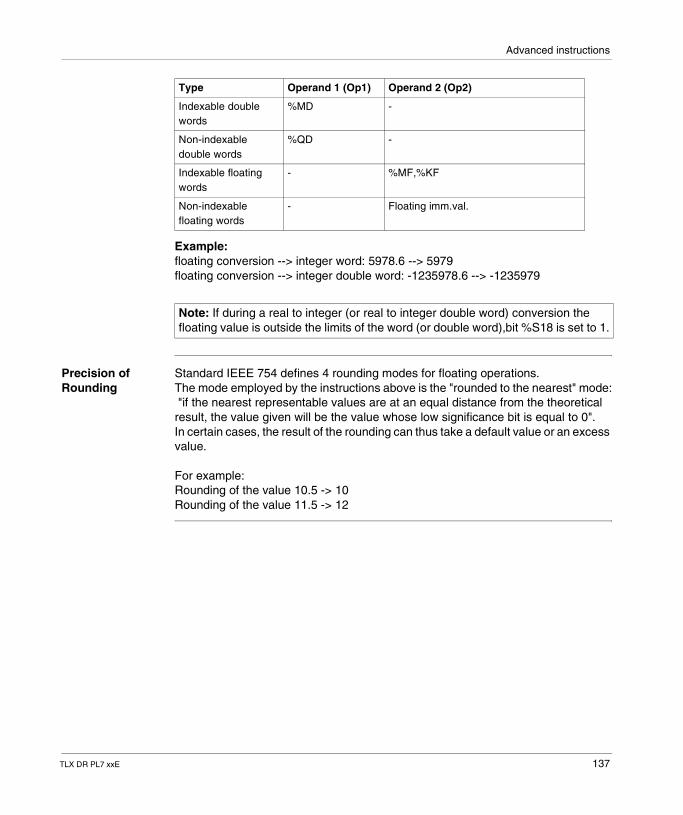
Advanced instructions
Example: floating conversion --> integer word: 5978.6 --> 5979 floating conversion --> integer double word: -1235978.6 --> -1235979
Precision of Rounding
Standard IEEE 754 defines 4 rounding modes for floating operations.The mode employed by the instructions above is the "rounded to the nearest" mode: "if the nearest representable values are at an equal distance from the theoretical result, the value given will be the value whose low significance bit is equal to 0".In certain cases, the result of the rounding can thus take a default value or an excess value.
For example:Rounding of the value 10.5 -> 10Rounding of the value 11.5 -> 12
Indexable double words
%MD -
Non-indexable double words
%QD -
Indexable floating words
- %MF,%KF
Non-indexable floating words
- Floating imm.val.
Note: If during a real to integer (or real to integer double word) conversion the floating value is outside the limits of the word (or double word),bit %S18 is set to 1.
Type Operand 1 (Op1) Operand 2 (Op2)
TLX DR PL7 xxE 137
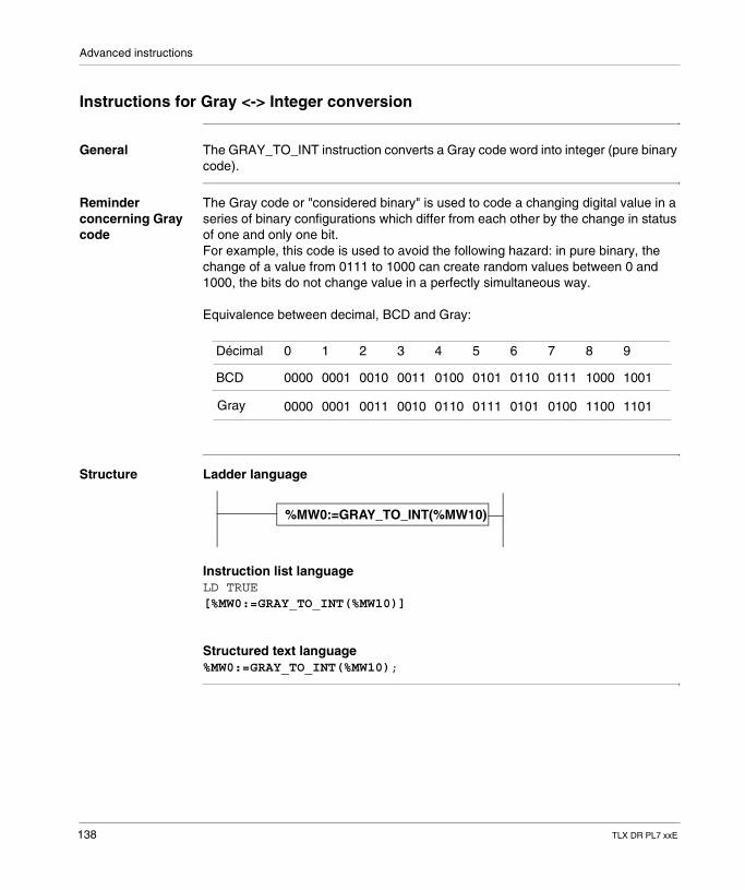
Advanced instructions
Instructions for Gray <-> Integer conversion
General The GRAY_TO_INT instruction converts a Gray code word into integer (pure binary code).
Reminder concerning Gray code
The Gray code or "considered binary" is used to code a changing digital value in a series of binary configurations which differ from each other by the change in status of one and only one bit. For example, this code is used to avoid the following hazard: in pure binary, the change of a value from 0111 to 1000 can create random values between 0 and 1000, the bits do not change value in a perfectly simultaneous way.
Equivalence between decimal, BCD and Gray:
Structure Ladder language
Instruction list languageLD TRUE[%MW0:=GRAY_TO_INT(%MW10)]
Structured text language%MW0:=GRAY_TO_INT(%MW10);
Décimal 0 1 2 3 4 5 6 7 8 9
BCD 0000 0001 0010 0011 0100 0101 0110 0111 1000 1001
Gray 0000 0001 0011 0010 0110 0111 0101 0100 1100 1101
%MW0:=GRAY_TO_INT(%MW10)
138 TLX DR PL7 xxE
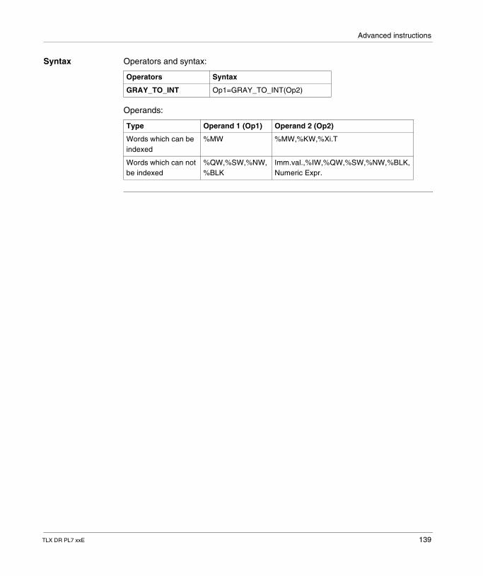
Advanced instructions
Syntax Operators and syntax:
Operands:
Operators Syntax
GRAY_TO_INT Op1=GRAY_TO_INT(Op2)
Type Operand 1 (Op1) Operand 2 (Op2)
Words which can be indexed
%MW %MW,%KW,%Xi.T
Words which can not be indexed
%QW,%SW,%NW,%BLK
Imm.val.,%IW,%QW,%SW,%NW,%BLK, Numeric Expr.
TLX DR PL7 xxE 139
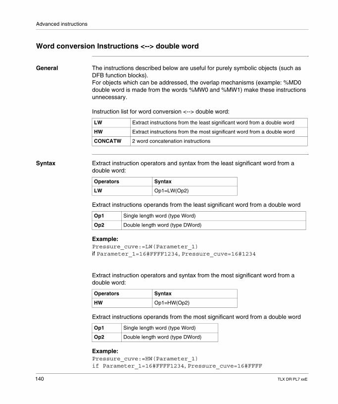
Advanced instructions
Word conversion Instructions <--> double word
General The instructions described below are useful for purely symbolic objects (such as DFB function blocks).For objects which can be addressed, the overlap mechanisms (example: %MD0 double word is made from the words %MW0 and %MW1) make these instructions unnecessary.
Instruction list for word conversion <--> double word:
Syntax Extract instruction operators and syntax from the least significant word from a double word:
Extract instructions operands from the least significant word from a double word
Example:Pressure_cuve:=LW(Parameter_1)if Parameter_1=16#FFFF1234, Pressure_cuve=16#1234
Extract instruction operators and syntax from the most significant word from a double word:
Extract instructions operands from the most significant word from a double word
Example:Pressure_cuve:=HW(Parameter_1)if Parameter_1=16#FFFF1234, Pressure_cuve=16#FFFF
LW Extract instructions from the least significant word from a double word
HW Extract instructions from the most significant word from a double word
CONCATW 2 word concatenation instructions
Operators Syntax
LW Op1=LW(Op2)
Op1 Single length word (type Word)
Op2 Double length word (type DWord)
Operators Syntax
HW Op1=HW(Op2)
Op1 Single length word (type Word)
Op2 Double length word (type DWord)
140 TLX DR PL7 xxE
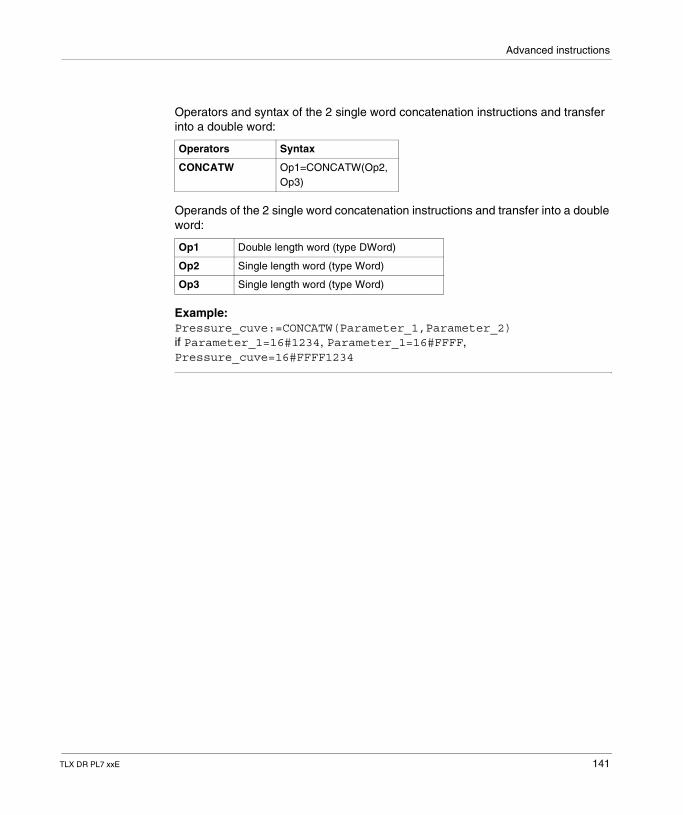
Advanced instructions
Operators and syntax of the 2 single word concatenation instructions and transfer into a double word:
Operands of the 2 single word concatenation instructions and transfer into a double word:
Example:Pressure_cuve:=CONCATW(Parameter_1,Parameter_2)if Parameter_1=16#1234, Parameter_1=16#FFFF, Pressure_cuve=16#FFFF1234
Operators Syntax
CONCATW Op1=CONCATW(Op2,Op3)
Op1 Double length word (type DWord)
Op2 Single length word (type Word)
Op3 Single length word (type Word)
TLX DR PL7 xxE 141
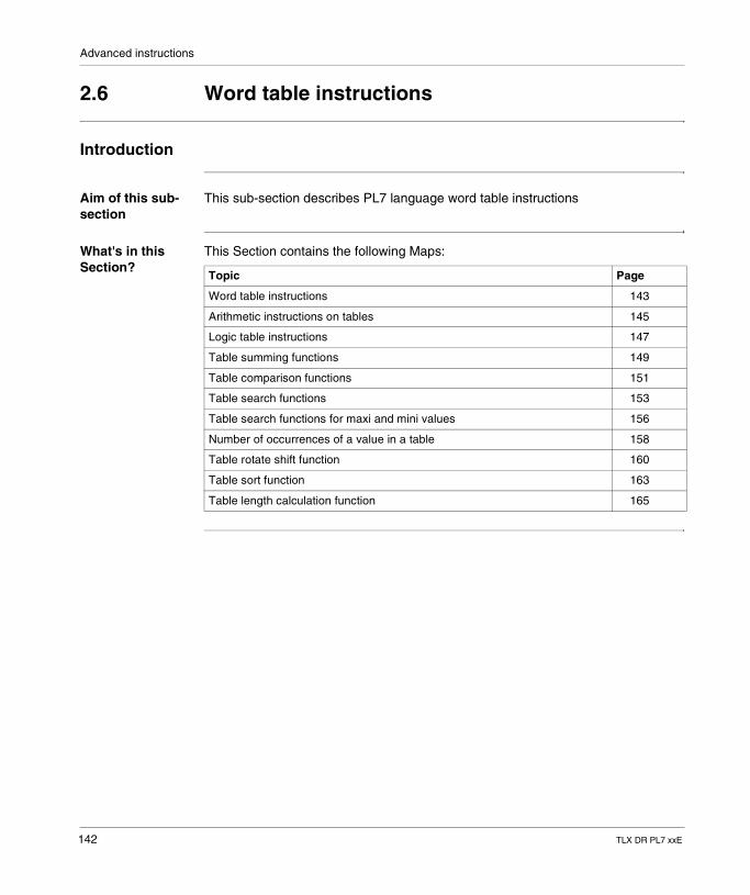
Advanced instructions
2.6 Word table instructions
Introduction
Aim of this sub-section
This sub-section describes PL7 language word table instructions
What's in this Section?
This Section contains the following Maps:
Topic Page
Word table instructions 143
Arithmetic instructions on tables 145
Logic table instructions 147
Table summing functions 149
Table comparison functions 151
Table search functions 153
Table search functions for maxi and mini values 156
Number of occurrences of a value in a table 158
Table rotate shift function 160
Table sort function 163
Table length calculation function 165
142 TLX DR PL7 xxE
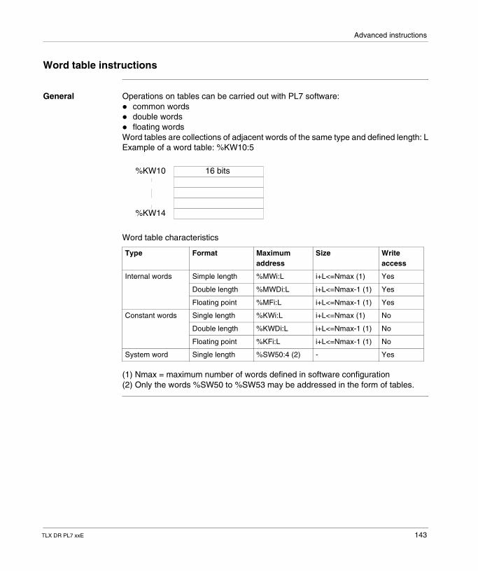
Advanced instructions
Word table instructions
General Operations on tables can be carried out with PL7 software: � common words� double words� floating wordsWord tables are collections of adjacent words of the same type and defined length: LExample of a word table: %KW10:5
Word table characteristics
(1) Nmax = maximum number of words defined in software configuration(2) Only the words %SW50 to %SW53 may be addressed in the form of tables.
Type Format Maximum address
Size Write access
Internal words Simple length %MWi:L i+L<=Nmax (1) Yes
Double length %MWDi:L i+L<=Nmax-1 (1) Yes
Floating point %MFi:L i+L<=Nmax-1 (1) Yes
Constant words Single length %KWi:L i+L<=Nmax (1) No
Double length %KWDi:L i+L<=Nmax-1 (1) No
Floating point %KFi:L i+L<=Nmax-1 (1) No
System word Single length %SW50:4 (2) - Yes
16 bits%KW10
%KW14
TLX DR PL7 xxE 143
Advanced instructions
General rules on table operations
� table operations can only be carried out on tables containing objects of the same type
� table operations can only be carried out on a maximum of 2 tables� if the tables in an operation are of different sizes, the result table will correspond
to the smaller of the 2 operand tables� the user must avoid carrying out operations on tables with overlap (for example:
%MW100[20]:=%MW90[20]+%KW100[20])� an operation on 2 tables is carried out on each element of the same rank in both
tables and the result is transferred into the element of the same rank in the result table
� if during an operation between 2 elements, the system bit %S18 is set at 1, the result for this operation is invalid, but the operation for the following elements is carried out correctly
� when one of the operands is a numeric expression, this must be put between brackets
� the rank of a word in a table corresponds to the position of the word in the table; the first position corresponds to rank 0
144 TLX DR PL7 xxE
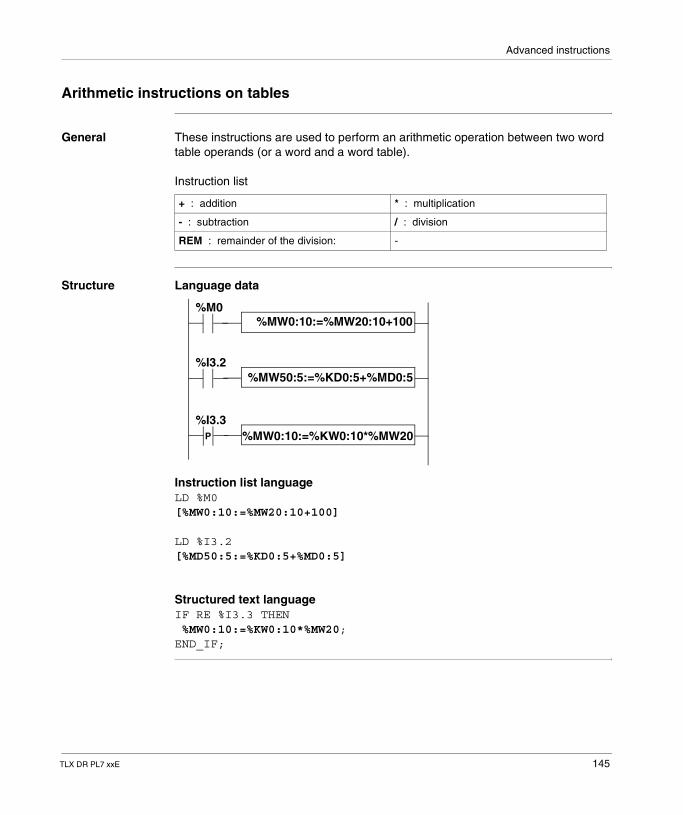
Advanced instructions
Arithmetic instructions on tables
General These instructions are used to perform an arithmetic operation between two word table operands (or a word and a word table).
Instruction list
Structure Language data
Instruction list languageLD %M0[%MW0:10:=%MW20:10+100]
LD %I3.2[%MD50:5:=%KD0:5+%MD0:5]
Structured text languageIF RE %I3.3 THEN %MW0:10:=%KW0:10*%MW20;END_IF;
+ : addition * : multiplication
- : subtraction / : division
REM : remainder of the division: -
%MW0:10:=%MW20:10+100%M0
%MW50:5:=%KD0:5+%MD0:5%I3.2
%MW0:10:=%KW0:10*%MW20%I3.3
P
TLX DR PL7 xxE 145
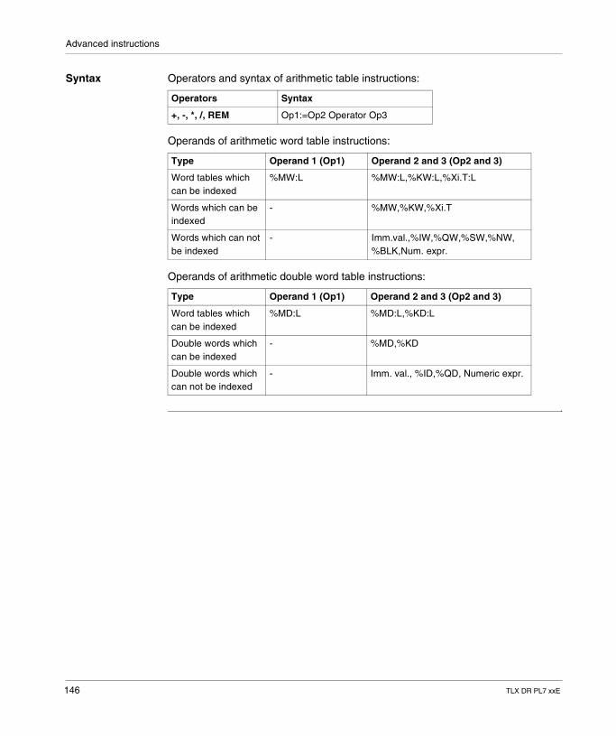
Advanced instructions
Syntax Operators and syntax of arithmetic table instructions:
Operands of arithmetic word table instructions:
Operands of arithmetic double word table instructions:
Operators Syntax
+, -, *, /, REM Op1:=Op2 Operator Op3
Type Operand 1 (Op1) Operand 2 and 3 (Op2 and 3)
Word tables which can be indexed
%MW:L %MW:L,%KW:L,%Xi.T:L
Words which can be indexed
- %MW,%KW,%Xi.T
Words which can not be indexed
- Imm.val.,%IW,%QW,%SW,%NW, %BLK,Num. expr.
Type Operand 1 (Op1) Operand 2 and 3 (Op2 and 3)
Word tables which can be indexed
%MD:L %MD:L,%KD:L
Double words which can be indexed
- %MD,%KD
Double words which can not be indexed
- Imm. val., %ID,%QD, Numeric expr.
146 TLX DR PL7 xxE
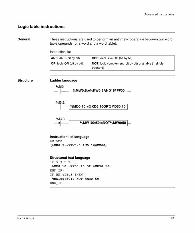
Advanced instructions
Logic table instructions
General These instructions are used to perform an arithmetic operation between two word table operands (or a word and a word table).
Instruction list
Structure Ladder language
Instruction list languageLD %M0[%MW0:5:=%KW0:5 AND 16#FF00]
Structured text languageIF %I3.2 THEN %MD0:10:=%KD5:10 OR %MD50:10;END_IF;IF RE %I3.3 THEN %MW100:50:= NOT %MW0:50;END_IF;
AND: AND (bit by bit) XOR: exclusive OR (bit by bit)
OR: logic OR (bit by bit) NOT: logic complement (bit by bit) of a table (1 single operand)
%MD0:10:=%KD5:10OR%MD50:10
%M0
%I3.2
%I3.3P
%MW0:5:=%KW0:5AND16#FF00
%MW100:50:=NOT%MW0:50
TLX DR PL7 xxE 147
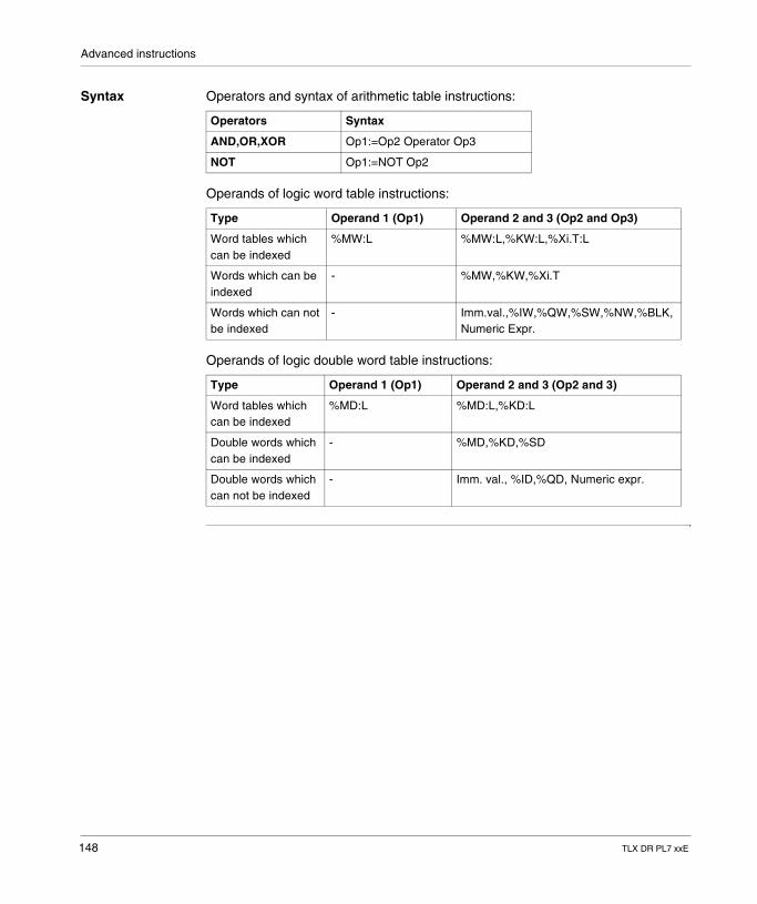
Advanced instructions
Syntax Operators and syntax of arithmetic table instructions:
Operands of logic word table instructions:
Operands of logic double word table instructions:
Operators Syntax
AND,OR,XOR Op1:=Op2 Operator Op3
NOT Op1:=NOT Op2
Type Operand 1 (Op1) Operand 2 and 3 (Op2 and Op3)
Word tables which can be indexed
%MW:L %MW:L,%KW:L,%Xi.T:L
Words which can be indexed
- %MW,%KW,%Xi.T
Words which can not be indexed
- Imm.val.,%IW,%QW,%SW,%NW,%BLK, Numeric Expr.
Type Operand 1 (Op1) Operand 2 and 3 (Op2 and 3)
Word tables which can be indexed
%MD:L %MD:L,%KD:L
Double words which can be indexed
- %MD,%KD,%SD
Double words which can not be indexed
- Imm. val., %ID,%QD, Numeric expr.
148 TLX DR PL7 xxE
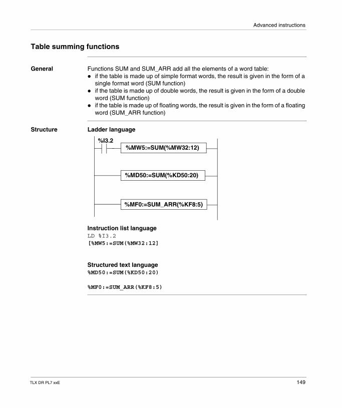
Advanced instructions
Table summing functions
General Functions SUM and SUM_ARR add all the elements of a word table:� if the table is made up of simple format words, the result is given in the form of a
single format word (SUM function)� if the table is made up of double words, the result is given in the form of a double
word (SUM function)� if the table is made up of floating words, the result is given in the form of a floating
word (SUM_ARR function)
Structure Ladder language
Instruction list languageLD %I3.2[%MW5:=SUM(%MW32:12]
Structured text language%MD50:=SUM(%KD50:20)
%MF0:=SUM_ARR(%KF8:5)
%I3.2%MW5:=SUM(%MW32:12)
%MF0:=SUM_ARR(%KF8:5)
%MD50:=SUM(%KD50:20)
TLX DR PL7 xxE 149
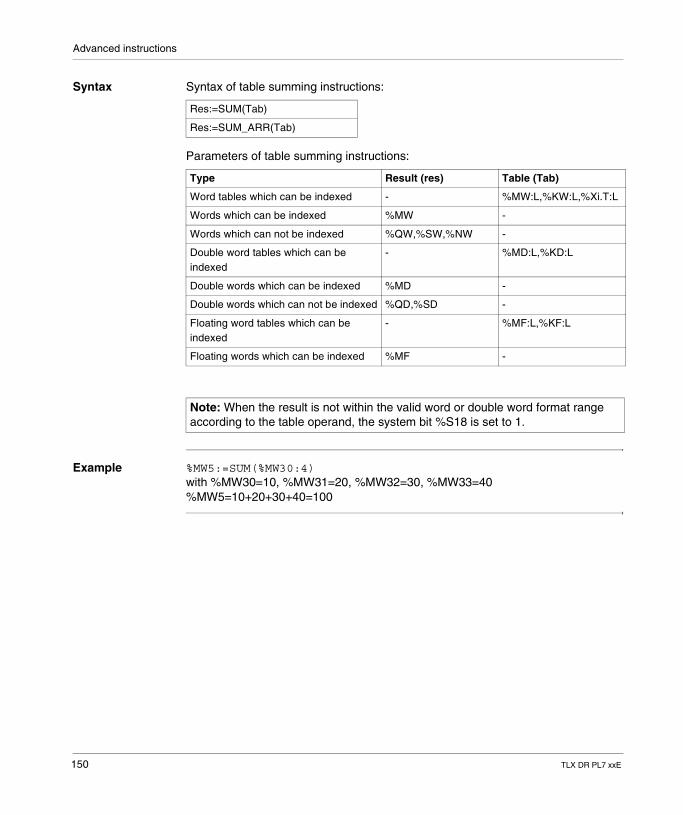
Advanced instructions
Syntax Syntax of table summing instructions:
Parameters of table summing instructions:
Example %MW5:=SUM(%MW30:4)with %MW30=10, %MW31=20, %MW32=30, %MW33=40%MW5=10+20+30+40=100
Res:=SUM(Tab)
Res:=SUM_ARR(Tab)
Type Result (res) Table (Tab)
Word tables which can be indexed - %MW:L,%KW:L,%Xi.T:L
Words which can be indexed %MW -
Words which can not be indexed %QW,%SW,%NW -
Double word tables which can be indexed
- %MD:L,%KD:L
Double words which can be indexed %MD -
Double words which can not be indexed %QD,%SD -
Floating word tables which can be indexed
- %MF:L,%KF:L
Floating words which can be indexed %MF -
Note: When the result is not within the valid word or double word format range according to the table operand, the system bit %S18 is set to 1.
150 TLX DR PL7 xxE
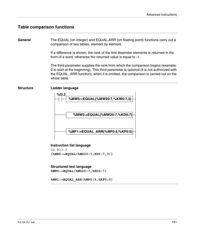
Advanced instructions
Table comparison functions
General The EQUAL (on integer) and EQUAL-ARR (on floating point) functions carry out a comparison of two tables, element by element.
If a difference is shown, the rank of the first dissimilar elements is returned in the form of a word, otherwise the returned value is equal to -1.
The third parameter supplies the rank from which the comparison begins (example: 0 to start at the beginning). This third parameter is optional (it is not authorized with the EQUAL_ARR function); when it is omitted, the comparison is carried out on the whole table.
Structure Ladder language
Instruction list languageLD %I3.2[%MW5:=EQUAL(%MD20:7,KD0:7,3)]
Structured text language%MW0:=EQUAL(%MD20:7,%KD0:7)
%MW1:=EQUAL_ARR(%MF0:5,%KF0:5)
%MW5:=EQUAL(%MW20:7,%KW0:7,3)%I3.2
%MW0:=EQUAL(%MW20:7,%KD0:7)
%MF1:=EQUAL_ARR(%MF0:5,%KF0:5)
TLX DR PL7 xxE 151
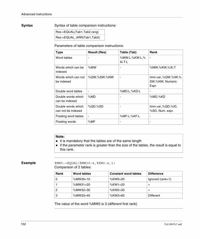
Advanced instructions
Syntax Syntax of table comparison instructions:
Parameters of table comparison instructions:
Example %MW5:=EQUAL(%MW30:4,%KW0:4,1)Comparison of 2 tables:
The value of the word %MW5 is 3 (different first rank)
Res:=EQUAL(Tab1,Tab2,rang)
Res:=EQUAL_ARR(Tab1,Tab2)
Type Result (Res) Table (Tab) Rank
Word tables - %MW:L,%KW:L,%Xi.T:L
-
Words which can be indexed
%MW - %MW,%KW,%Xi.T
Words which can not be indexed
%QW,%SW,%NW - Imm.val.,%QW,%IW,%SW,%NW, Numeric Expr.
Double word tables - %MD:L,%KD:L -
Double words which can be indexed
%MD - %MD,%KD
Double words which can not be indexed
%QD,%SD - Imm.val.,%QD,%ID, %SD, Num. expr.
Floating word tables - %MF:L,%KF:L -
Floating words %MF - -
Note: � it is mandatory that the tables are of the same length� if the parameter rank is greater than the size of the tables, the result is equal to
this rank.
Rank Word tables Constant word tables Difference
0 %MW30=10 %KW0=20 Ignored (rank<1)
1 %MW31=20 %KW1=20 =
2 %MW32=30 %KW2=30 =
3 %MW33=40 %KW3=60 Different
152 TLX DR PL7 xxE
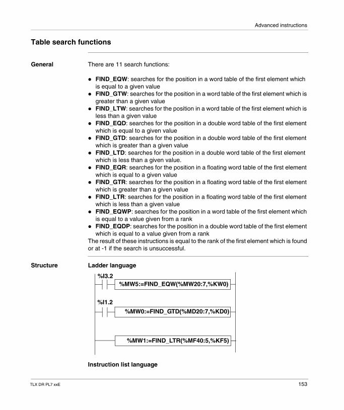
Advanced instructions
Table search functions
General There are 11 search functions:
� FIND_EQW: searches for the position in a word table of the first element which is equal to a given value
� FIND_GTW: searches for the position in a word table of the first element which is greater than a given value
� FIND_LTW: searches for the position in a word table of the first element which is less than a given value
� FIND_EQD: searches for the position in a double word table of the first element which is equal to a given value
� FIND_GTD: searches for the position in a double word table of the first element which is greater than a given value
� FIND_LTD: searches for the position in a double word table of the first element which is less than a given value.
� FIND_EQR: searches for the position in a floating word table of the first element which is equal to a given value
� FIND_GTR: searches for the position in a floating word table of the first element which is greater than a given value
� FIND_LTR: searches for the position in a floating word table of the first element which is less than a given value
� FIND_EQWP: searches for the position in a word table of the first element which is equal to a value given from a rank
� FIND_EQDP: searches for the position in a double word table of the first element which is equal to a value given from a rank
The result of these instructions is equal to the rank of the first element which is found or at -1 if the search is unsuccessful.
Structure Ladder language
Instruction list language
%MW5:=FIND_EQW(%MW20:7,%KW0)%I3.2
%MW0:=FIND_GTD(%MD20:7,%KD0)
%MW1:=FIND_LTR(%MF40:5,%KF5)
%I1.2
TLX DR PL7 xxE 153
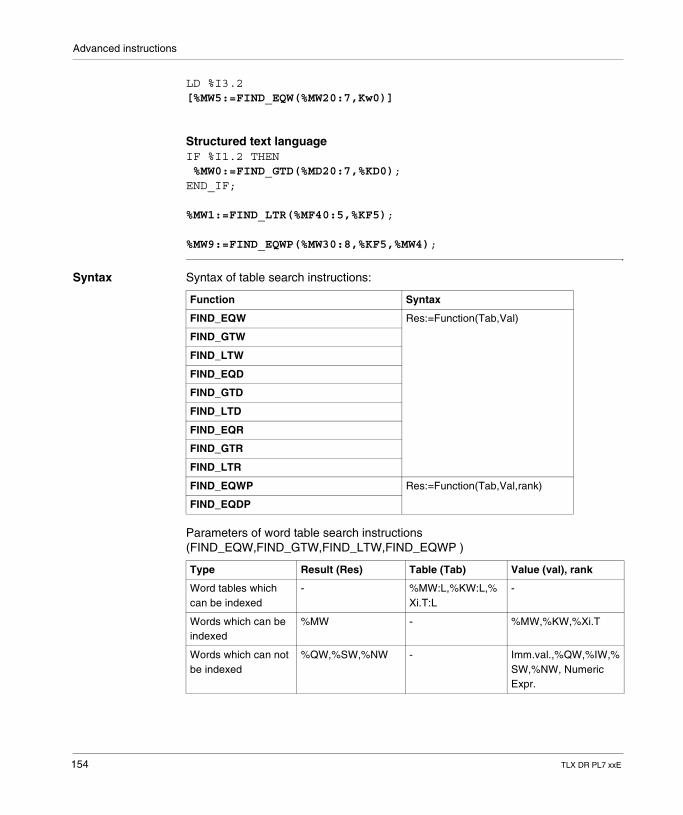
Advanced instructions
LD %I3.2[%MW5:=FIND_EQW(%MW20:7,Kw0)]
Structured text languageIF %I1.2 THEN %MW0:=FIND_GTD(%MD20:7,%KD0);END_IF;
%MW1:=FIND_LTR(%MF40:5,%KF5);
%MW9:=FIND_EQWP(%MW30:8,%KF5,%MW4);
Syntax Syntax of table search instructions:
Parameters of word table search instructions (FIND_EQW,FIND_GTW,FIND_LTW,FIND_EQWP )
Function Syntax
FIND_EQW Res:=Function(Tab,Val)
FIND_GTW
FIND_LTW
FIND_EQD
FIND_GTD
FIND_LTD
FIND_EQR
FIND_GTR
FIND_LTR
FIND_EQWP Res:=Function(Tab,Val,rank)
FIND_EQDP
Type Result (Res) Table (Tab) Value (val), rank
Word tables which can be indexed
- %MW:L,%KW:L,%Xi.T:L
-
Words which can be indexed
%MW - %MW,%KW,%Xi.T
Words which can not be indexed
%QW,%SW,%NW - Imm.val.,%QW,%IW,%SW,%NW, Numeric Expr.
154 TLX DR PL7 xxE
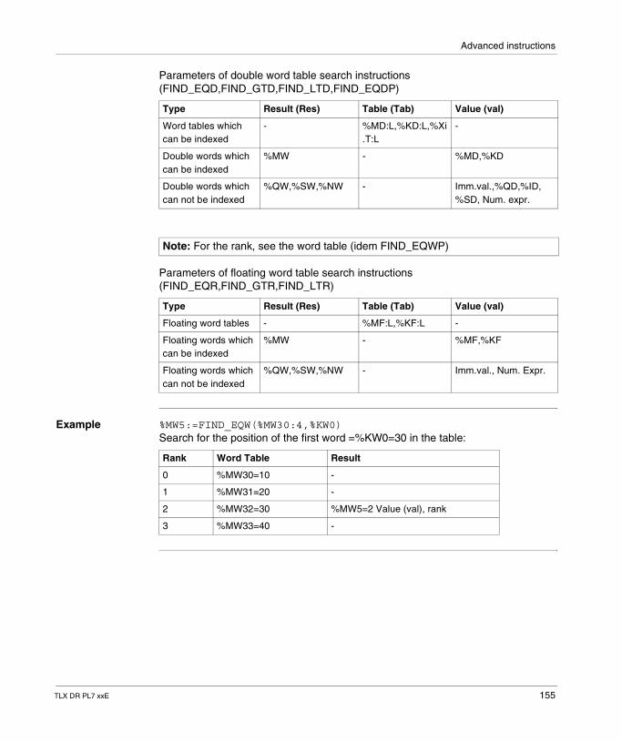
Advanced instructions
Parameters of double word table search instructions (FIND_EQD,FIND_GTD,FIND_LTD,FIND_EQDP)
Parameters of floating word table search instructions (FIND_EQR,FIND_GTR,FIND_LTR)
Example %MW5:=FIND_EQW(%MW30:4,%KW0)Search for the position of the first word =%KW0=30 in the table:
Type Result (Res) Table (Tab) Value (val)
Word tables which can be indexed
- %MD:L,%KD:L,%Xi.T:L
-
Double words which can be indexed
%MW - %MD,%KD
Double words which can not be indexed
%QW,%SW,%NW - Imm.val.,%QD,%ID, %SD, Num. expr.
Note: For the rank, see the word table (idem FIND_EQWP)
Type Result (Res) Table (Tab) Value (val)
Floating word tables - %MF:L,%KF:L -
Floating words which can be indexed
%MW - %MF,%KF
Floating words which can not be indexed
%QW,%SW,%NW - Imm.val., Num. Expr.
Rank Word Table Result
0 %MW30=10 -
1 %MW31=20 -
2 %MW32=30 %MW5=2 Value (val), rank
3 %MW33=40 -
TLX DR PL7 xxE 155
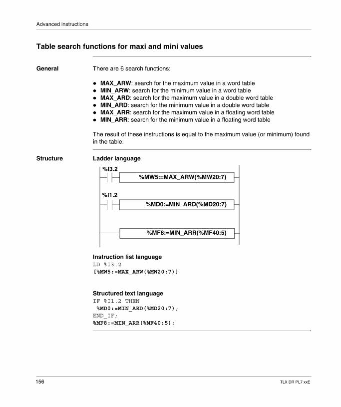
Advanced instructions
Table search functions for maxi and mini values
General There are 6 search functions:
� MAX_ARW: search for the maximum value in a word table� MIN_ARW: search for the minimum value in a word table� MAX_ARD: search for the maximum value in a double word table� MIN_ARD: search for the minimum value in a double word table� MAX_ARR: search for the maximum value in a floating word table� MIN_ARR: search for the minimum value in a floating word table
The result of these instructions is equal to the maximum value (or minimum) found in the table.
Structure Ladder language
Instruction list languageLD %I3.2[%MW5:=MAX_ARW(%MW20:7)]
Structured text languageIF %I1.2 THEN %MD0:=MIN_ARD(%MD20:7);END_IF;%MF8:=MIN_ARR(%MF40:5);
%MW5:=MAX_ARW(%MW20:7)%I3.2
%MD0:=MIN_ARD(%MD20:7)
%MF8:=MIN_ARR(%MF40:5)
%I1.2
156 TLX DR PL7 xxE
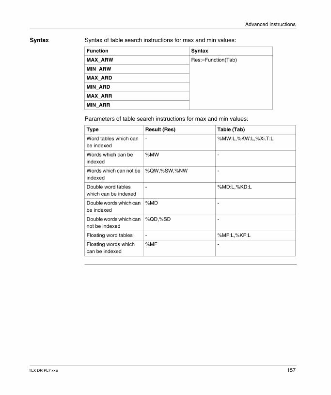
Advanced instructions
Syntax Syntax of table search instructions for max and min values:
Parameters of table search instructions for max and min values:
Function Syntax
MAX_ARW Res:=Function(Tab)
MIN_ARW
MAX_ARD
MIN_ARD
MAX_ARR
MIN_ARR
Type Result (Res) Table (Tab)
Word tables which can be indexed
- %MW:L,%KW:L,%Xi.T:L
Words which can be indexed
%MW -
Words which can not be indexed
%QW,%SW,%NW -
Double word tables which can be indexed
- %MD:L,%KD:L
Double words which can be indexed
%MD -
Double words which can not be indexed
%QD,%SD -
Floating word tables - %MF:L,%KF:L
Floating words which can be indexed
%MF -
TLX DR PL7 xxE 157
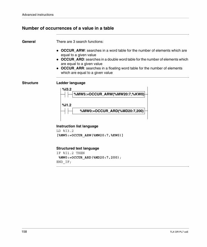
Advanced instructions
Number of occurrences of a value in a table
General There are 3 search functions:
� OCCUR_ARW: searches in a word table for the number of elements which are equal to a given value
� OCCUR_ARD: searches in a double word table for the number of elements which are equal to a given value
� OCCUR_ARR: searches in a floating word table for the number of elements which are equal to a given value
Structure Ladder language
Instruction list languageLD %I3.2[%MW5:=OCCUR_ARW(%MW20:7,%KW0)]
Structured text languageIF %I1.2 THEN %MW0:=OCCUR_ARD(%MD20:7,200);END_IF;
%MW5:=OCCUR_ARW(%MW20:7,%KW0)%I3.2
%MW0:=OCCUR_ARD(%MD20:7,200)
%I1.2
158 TLX DR PL7 xxE
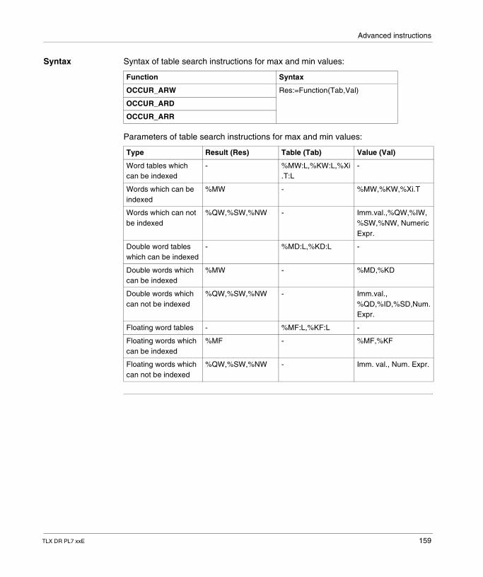
Advanced instructions
Syntax Syntax of table search instructions for max and min values:
Parameters of table search instructions for max and min values:
Function Syntax
OCCUR_ARW Res:=Function(Tab,Val)
OCCUR_ARD
OCCUR_ARR
Type Result (Res) Table (Tab) Value (Val)
Word tables which can be indexed
- %MW:L,%KW:L,%Xi.T:L
-
Words which can be indexed
%MW - %MW,%KW,%Xi.T
Words which can not be indexed
%QW,%SW,%NW - Imm.val.,%QW,%IW,%SW,%NW, Numeric Expr.
Double word tables which can be indexed
- %MD:L,%KD:L -
Double words which can be indexed
%MW - %MD,%KD
Double words which can not be indexed
%QW,%SW,%NW - Imm.val., %QD,%ID,%SD,Num. Expr.
Floating word tables - %MF:L,%KF:L -
Floating words which can be indexed
%MF - %MF,%KF
Floating words which can not be indexed
%QW,%SW,%NW - Imm. val., Num. Expr.
TLX DR PL7 xxE 159
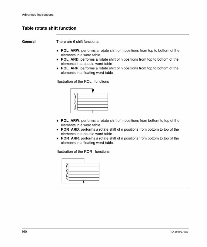
Advanced instructions
Table rotate shift function
General There are 6 shift functions:
� ROL_ARW: performs a rotate shift of n positions from top to bottom of the elements in a word table
� ROL_ARD: performs a rotate shift of n positions from top to bottom of the elements in a double word table
� ROL_ARR: performs a rotate shift of n positions from top to bottom of the elements in a floating word table
Illustration of the ROL_ functions
� ROL_ARW: performs a rotate shift of n positions from bottom to top of the elements in a word table
� ROR_ARD: performs a rotate shift of n positions from bottom to top of the elements in a double word table
� ROR_ARR: performs a rotate shift of n positions from bottom to top of the elements in a floating word table
Illustration of the ROR_ functions
012345
012345
160 TLX DR PL7 xxE
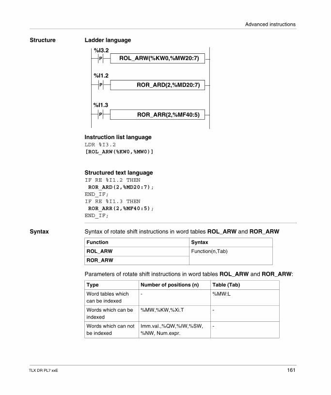
Advanced instructions
Structure Ladder language
Instruction list languageLDR %I3.2[ROL_ARW(%KW0,%MW0)]
Structured text languageIF RE %I1.2 THEN ROR_ARD(2,%MD20:7);END_IF;IF RE %I1.3 THEN ROR_ARR(2,%MF40:5);END_IF;
Syntax Syntax of rotate shift instructions in word tables ROL_ARW and ROR_ARW
Parameters of rotate shift instructions in word tables ROL_ARW and ROR_ARW:
ROL_ARW(%KW0,%MW20:7)%I3.2
ROR_ARD(2,%MD20:7)
%I1.2
P
P
ROR_ARR(2,%MF40:5)
%I1.3
P
Function Syntax
ROL_ARW Function(n,Tab)
ROR_ARW
Type Number of positions (n) Table (Tab)
Word tables which can be indexed
- %MW:L
Words which can be indexed
%MW,%KW,%Xi.T -
Words which can not be indexed
Imm.val.,%QW,%IW,%SW, %NW, Num.expr.
-
TLX DR PL7 xxE 161
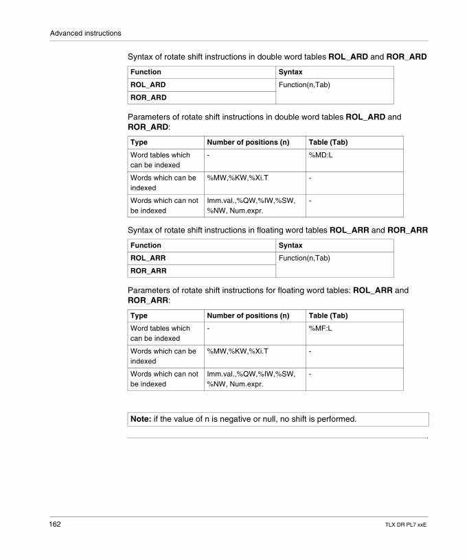
Advanced instructions
Syntax of rotate shift instructions in double word tables ROL_ARD and ROR_ARD
Parameters of rotate shift instructions in double word tables ROL_ARD and ROR_ARD:
Syntax of rotate shift instructions in floating word tables ROL_ARR and ROR_ARR
Parameters of rotate shift instructions for floating word tables: ROL_ARR and ROR_ARR:
Function Syntax
ROL_ARD Function(n,Tab)
ROR_ARD
Type Number of positions (n) Table (Tab)
Word tables which can be indexed
- %MD:L
Words which can be indexed
%MW,%KW,%Xi.T -
Words which can not be indexed
Imm.val.,%QW,%IW,%SW, %NW, Num.expr.
-
Function Syntax
ROL_ARR Function(n,Tab)
ROR_ARR
Type Number of positions (n) Table (Tab)
Word tables which can be indexed
- %MF:L
Words which can be indexed
%MW,%KW,%Xi.T -
Words which can not be indexed
Imm.val.,%QW,%IW,%SW, %NW, Num.expr.
-
Note: if the value of n is negative or null, no shift is performed.
162 TLX DR PL7 xxE
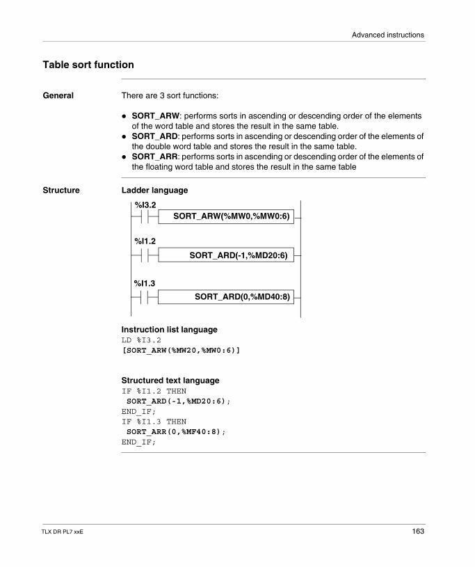
Advanced instructions
Table sort function
General There are 3 sort functions:
� SORT_ARW: performs sorts in ascending or descending order of the elements of the word table and stores the result in the same table.
� SORT_ARD: performs sorts in ascending or descending order of the elements of the double word table and stores the result in the same table.
� SORT_ARR: performs sorts in ascending or descending order of the elements of the floating word table and stores the result in the same table
Structure Ladder language
Instruction list languageLD %I3.2[SORT_ARW(%MW20,%MW0:6)]
Structured text languageIF %I1.2 THEN SORT_ARD(-1,%MD20:6);END_IF;IF %I1.3 THEN SORT_ARR(0,%MF40:8);END_IF;
SORT_ARW(%MW0,%MW0:6)%I3.2
SORT_ARD(-1,%MD20:6)
%I1.2
SORT_ARD(0,%MD40:8)
%I1.3
TLX DR PL7 xxE 163
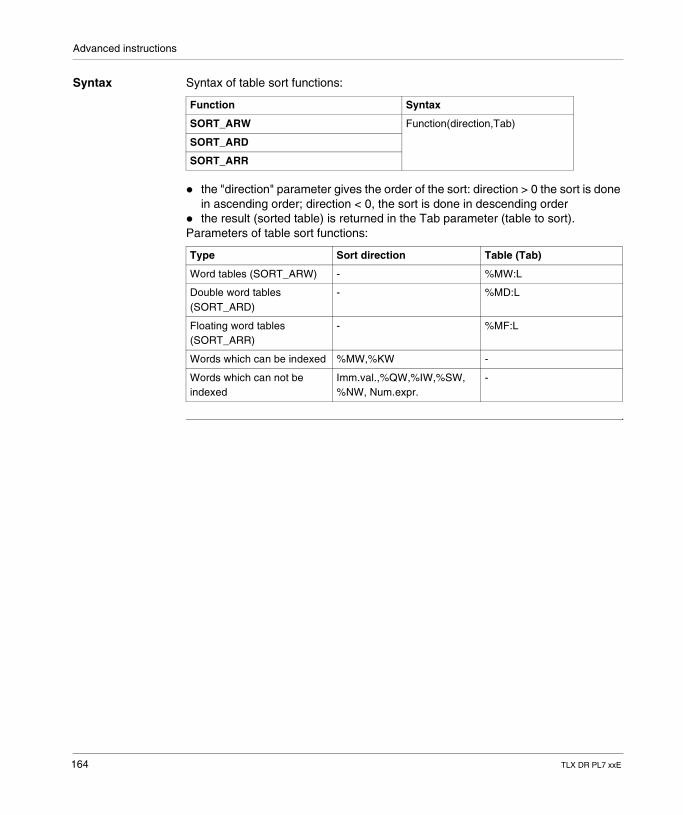
Advanced instructions
Syntax Syntax of table sort functions:
� the "direction" parameter gives the order of the sort: direction > 0 the sort is done in ascending order; direction < 0, the sort is done in descending order
� the result (sorted table) is returned in the Tab parameter (table to sort).Parameters of table sort functions:
Function Syntax
SORT_ARW Function(direction,Tab)
SORT_ARD
SORT_ARR
Type Sort direction Table (Tab)
Word tables (SORT_ARW) - %MW:L
Double word tables (SORT_ARD)
- %MD:L
Floating word tables (SORT_ARR)
- %MF:L
Words which can be indexed %MW,%KW -
Words which can not be indexed
Imm.val.,%QW,%IW,%SW, %NW, Num.expr.
-
164 TLX DR PL7 xxE
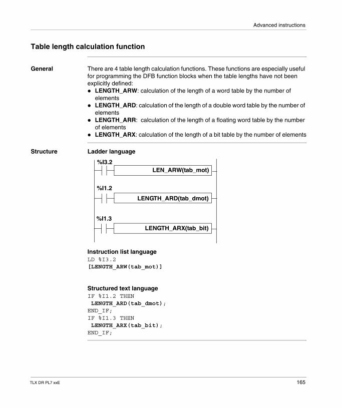
Advanced instructions
Table length calculation function
General There are 4 table length calculation functions. These functions are especially useful for programming the DFB function blocks when the table lengths have not been explicitly defined:� LENGTH_ARW: calculation of the length of a word table by the number of
elements� LENGTH_ARD: calculation of the length of a double word table by the number of
elements� LENGTH_ARR: calculation of the length of a floating word table by the number
of elements� LENGTH_ARX: calculation of the length of a bit table by the number of elements
Structure Ladder language
Instruction list languageLD %I3.2[LENGTH_ARW(tab_mot)]
Structured text languageIF %I1.2 THEN LENGTH_ARD(tab_dmot);END_IF;IF %I1.3 THEN LENGTH_ARX(tab_bit);END_IF;
LEN_ARW(tab_mot)%I3.2
LENGTH_ARD(tab_dmot)
%I1.2
LENGTH_ARX(tab_bit)
%I1.3
TLX DR PL7 xxE 165
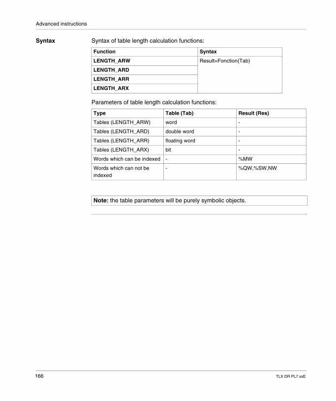
Advanced instructions
Syntax Syntax of table length calculation functions:
Parameters of table length calculation functions:
Function Syntax
LENGTH_ARW Result=Fonction(Tab)
LENGTH_ARD
LENGTH_ARR
LENGTH_ARX
Type Table (Tab) Result (Res)
Tables (LENGTH_ARW) word -
Tables (LENGTH_ARD) double word -
Tables (LENGTH_ARR) floating word -
Tables (LENGTH_ARX) bit -
Words which can be indexed - %MW
Words which can not be indexed
- %QW,%SW,NW
Note: the table parameters will be purely symbolic objects.
166 TLX DR PL7 xxE
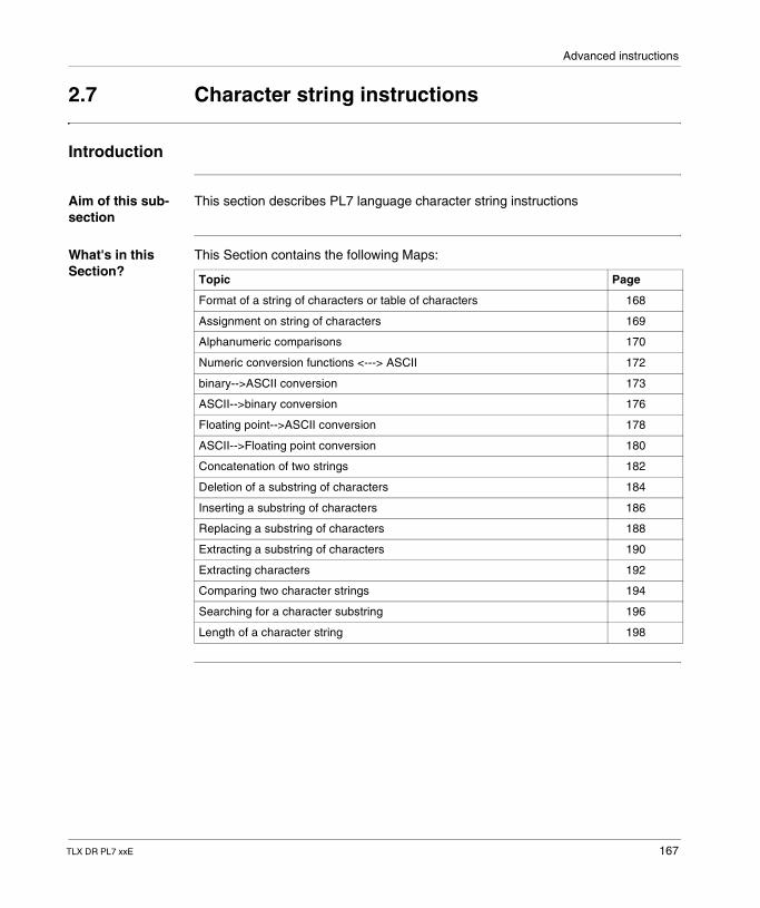
Advanced instructions
2.7 Character string instructions
Introduction
Aim of this sub-section
This section describes PL7 language character string instructions
What's in this Section?
This Section contains the following Maps:
Topic Page
Format of a string of characters or table of characters 168
Assignment on string of characters 169
Alphanumeric comparisons 170
Numeric conversion functions <---> ASCII 172
binary-->ASCII conversion 173
ASCII-->binary conversion 176
Floating point-->ASCII conversion 178
ASCII-->Floating point conversion 180
Concatenation of two strings 182
Deletion of a substring of characters 184
Inserting a substring of characters 186
Replacing a substring of characters 188
Extracting a substring of characters 190
Extracting characters 192
Comparing two character strings 194
Searching for a character substring 196
Length of a character string 198
TLX DR PL7 xxE 167
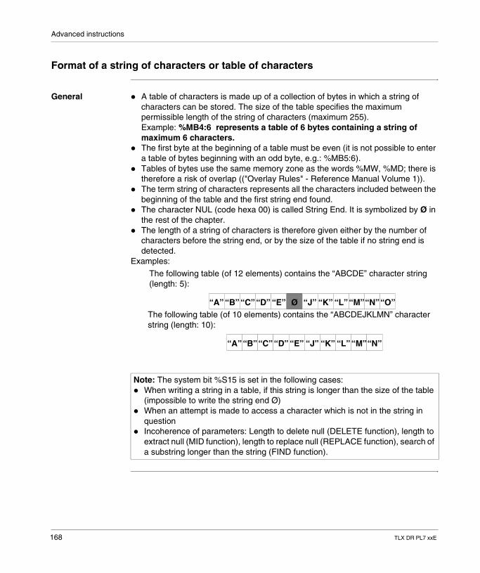
Advanced instructions
Format of a string of characters or table of characters
General � A table of characters is made up of a collection of bytes in which a string of characters can be stored. The size of the table specifies the maximum permissible length of the string of characters (maximum 255).Example: %MB4:6 represents a table of 6 bytes containing a string of maximum 6 characters.
� The first byte at the beginning of a table must be even (it is not possible to enter a table of bytes beginning with an odd byte, e.g.: %MB5:6).
� Tables of bytes use the same memory zone as the words %MW, %MD; there is therefore a risk of overlap (("Overlay Rules" - Reference Manual Volume 1)).
� The term string of characters represents all the characters included between the beginning of the table and the first string end found.
� The character NUL (code hexa 00) is called String End. It is symbolized by Ø in the rest of the chapter.
� The length of a string of characters is therefore given either by the number of characters before the string end, or by the size of the table if no string end is detected.
Examples:
Note: The system bit %S15 is set in the following cases:� When writing a string in a table, if this string is longer than the size of the table
(impossible to write the string end Ø)� When an attempt is made to access a character which is not in the string in
question� Incoherence of parameters: Length to delete null (DELETE function), length to
extract null (MID function), length to replace null (REPLACE function), search of a substring longer than the string (FIND function).
The following table (of 12 elements) contains the “ABCDE” character string (length: 5):
The following table (of 10 elements) contains the “ABCDEJKLMN” character string (length: 10):
“A” “B”“C”“D” “E” “J” “K” “L”“M”“N”“O”Ø
“A”“B”“C” “D” “E” “J” “K” “L”“M”“N”
168 TLX DR PL7 xxE
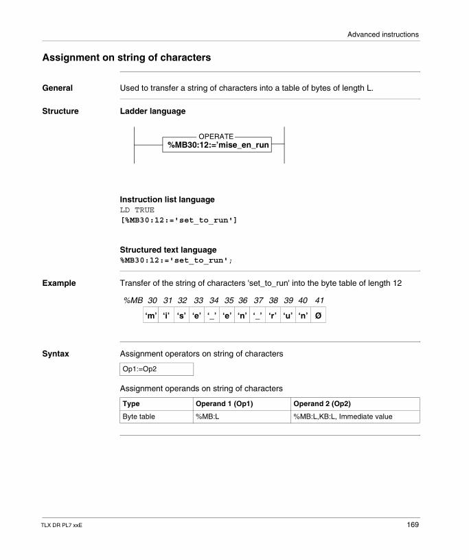
Advanced instructions
Assignment on string of characters
General Used to transfer a string of characters into a table of bytes of length L.
Structure Ladder language
Instruction list languageLD TRUE[%MB30:12:='set_to_run']
Structured text language%MB30:12:='set_to_run';
Example Transfer of the string of characters 'set_to_run' into the byte table of length 12
Syntax Assignment operators on string of characters
Assignment operands on string of characters
OPERATE%MB30:12:=’mise_en_run
%MB 30 31 32 33 34 35 36 37 38 39 40 41
‘m’ ‘i’ ‘s’ ‘e’ ‘_’ ‘e’ ‘n’ ‘_’ ‘r’ ‘u’ ‘n’ Ø
Op1:=Op2
Type Operand 1 (Op1) Operand 2 (Op2)
Byte table %MB:L %MB:L,KB:L, Immediate value
TLX DR PL7 xxE 169
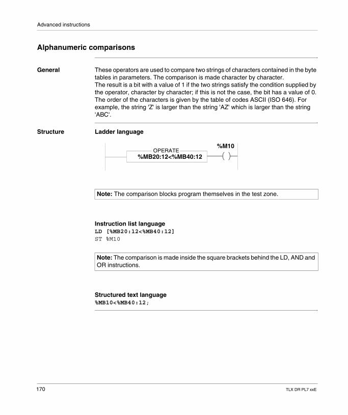
Advanced instructions
Alphanumeric comparisons
General These operators are used to compare two strings of characters contained in the byte tables in parameters. The comparison is made character by character.The result is a bit with a value of 1 if the two strings satisfy the condition supplied by the operator, character by character; if this is not the case, the bit has a value of 0.The order of the characters is given by the table of codes ASCII (ISO 646). For example, the string 'Z' is larger than the string 'AZ' which is larger than the string 'ABC'.
Structure Ladder language
Instruction list languageLD [%MB20:12<%MB40:12]ST %M10
Structured text language%MB10<%MB40:12;
Note: The comparison blocks program themselves in the test zone.
Note: The comparison is made inside the square brackets behind the LD, AND and OR instructions.
OPERATE%MB20:12<%MB40:12
%M10
170 TLX DR PL7 xxE
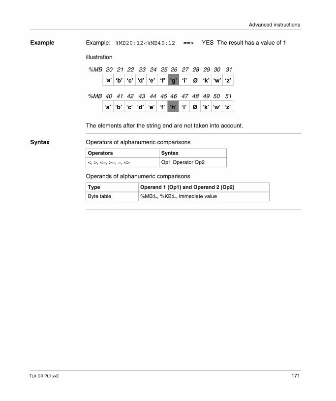
Advanced instructions
Example Example: %MB20:12<%MB40:12 ==> YES The result has a value of 1
illustration
The elements after the string end are not taken into account.
Syntax Operators of alphanumeric comparisons
Operands of alphanumeric comparisons
%MB 20 21 22 23 24 25 26 27 28 29 30 31
‘a’ ‘b’ ‘c’ ‘d’ ‘e’ ‘f’ ‘g’ ‘i’ Ø ‘k’ ‘w’ ‘z’
%MB 40 41 42 43 44 45 46 47 48 49 50 51
‘a’ ‘b’ ‘c’ ‘d’ ‘e’ ‘f’ ‘h’ ‘i’ Ø ‘k’ ‘w’ ‘z’
Operators Syntax
<, >, <=, >=, =, <> Op1 Operator Op2
Type Operand 1 (Op1) and Operand 2 (Op2)
Byte table %MB:L, %KB:L, immediate value
TLX DR PL7 xxE 171
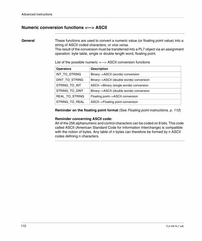
Advanced instructions
Numeric conversion functions <---> ASCII
General These functions are used to convert a numeric value (or floating point value) into a string of ASCII coded characters, or vice versa.The result of the conversion must be transferred into a PL7 object via an assignment operation: byte table, single or double length word, floating point.
List of the possible numeric <---> ASCII conversion functions
Reminder on the floating point format (See Floating point instructions, p. 112)
Reminder concerning ASCII code:All of the 256 alphanumeric and control characters can be coded on 8 bits. This code called ASCII (American Standard Code for Information Interchange) is compatible with the notion of bytes. Any table of n bytes can therefore be formed by n ASCII codes defining n characters.
Operators Description
INT_TO_STRING Binary-->ASCII (words) conversion
DINT_TO_STRING Binary-->ASCII (double words) conversion
STRING_TO_INT ASCII-->Binary (single words) conversion
STRING_TO_DINT Binary-->ASCII (double words) conversion
REAL_TO_STRING Floating point-->ASCII conversion
STRING_TO_REAL ASCII-->Floating point conversion
172 TLX DR PL7 xxE
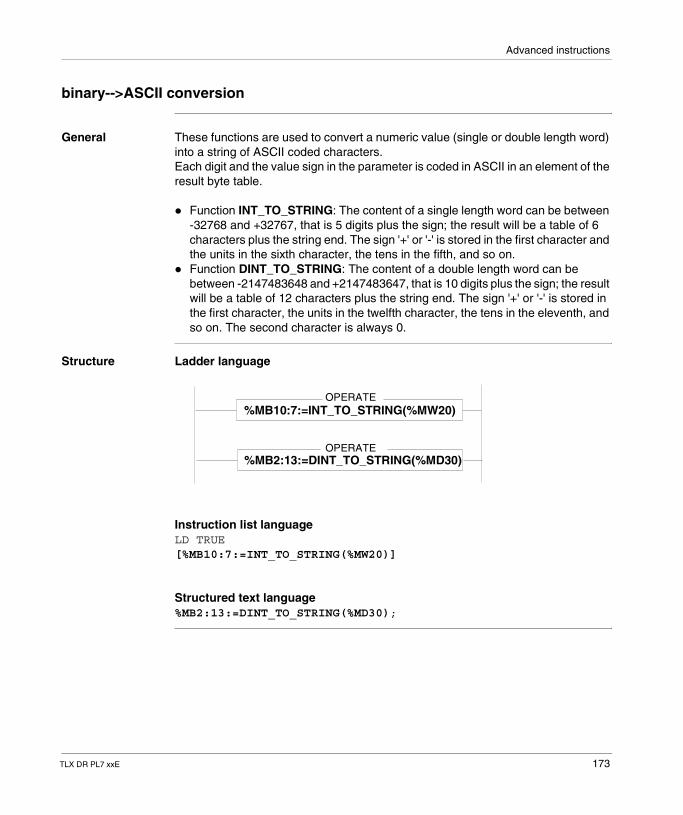
Advanced instructions
binary-->ASCII conversion
General These functions are used to convert a numeric value (single or double length word) into a string of ASCII coded characters.Each digit and the value sign in the parameter is coded in ASCII in an element of the result byte table.
� Function INT_TO_STRING: The content of a single length word can be between -32768 and +32767, that is 5 digits plus the sign; the result will be a table of 6 characters plus the string end. The sign '+' or '-' is stored in the first character and the units in the sixth character, the tens in the fifth, and so on.
� Function DINT_TO_STRING: The content of a double length word can be between -2147483648 and +2147483647, that is 10 digits plus the sign; the result will be a table of 12 characters plus the string end. The sign '+' or '-' is stored in the first character, the units in the twelfth character, the tens in the eleventh, and so on. The second character is always 0.
Structure Ladder language
Instruction list languageLD TRUE[%MB10:7:=INT_TO_STRING(%MW20)]
Structured text language%MB2:13:=DINT_TO_STRING(%MD30);
OPERATE%MB10:7:=INT_TO_STRING(%MW20)
OPERATE%MB2:13:=DINT_TO_STRING(%MD30)
TLX DR PL7 xxE 173
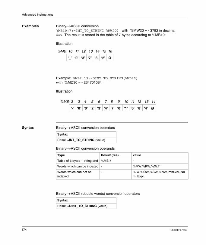
Advanced instructions
Examples Binary-->ASCII conversion%MB10:7:=INT_TO_STRING(%MW20) with %MW20 = - 3782 in decimal==> The result is stored in the table of 7 bytes according to %MB10:
Illustration
Example: %MB2:13:=DINT_TO_STRING(%MD30)with %MD30 = - 234701084
Illustration
Syntax Binary-->ASCII conversion operators
Binary-->ASCII conversion operands
Binary-->ASCII (double words) conversion operators
%MB 10 11 12 13 14 15 16
‘_’ ‘0’ ‘3’ ‘7’ ‘8’ ‘2’ Ø
%MB 2 3 4 5 6 7 8 9 10 11 12 13
‘-’ ‘0’ ‘0’ ‘2’ ‘3’ ‘4’ ‘7’ ‘0’ ‘1’ ‘0’ ‘8’ ‘4’
14
Ø
Syntax
Result:=INT_TO_STRING (value)
Type Result (res) value
Table of 6 bytes + string end %MB:7 -
Words which can be indexed - %MW,%KW,%Xi.T
Words which can not be indexed
- %IW,%QW,%SW,%NW,Imm.val.,Num. Expr.
Syntax
Result:=DINT_TO_STRING (value)
174 TLX DR PL7 xxE
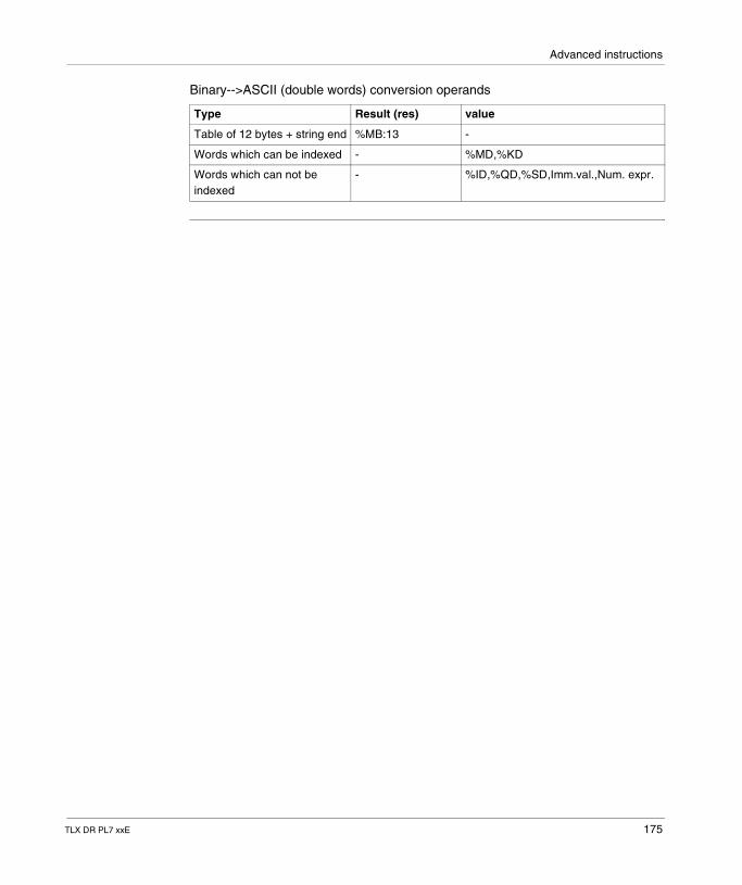
Advanced instructions
Binary-->ASCII (double words) conversion operands
Type Result (res) value
Table of 12 bytes + string end %MB:13 -
Words which can be indexed - %MD,%KD
Words which can not be indexed
- %ID,%QD,%SD,Imm.val.,Num. expr.
TLX DR PL7 xxE 175
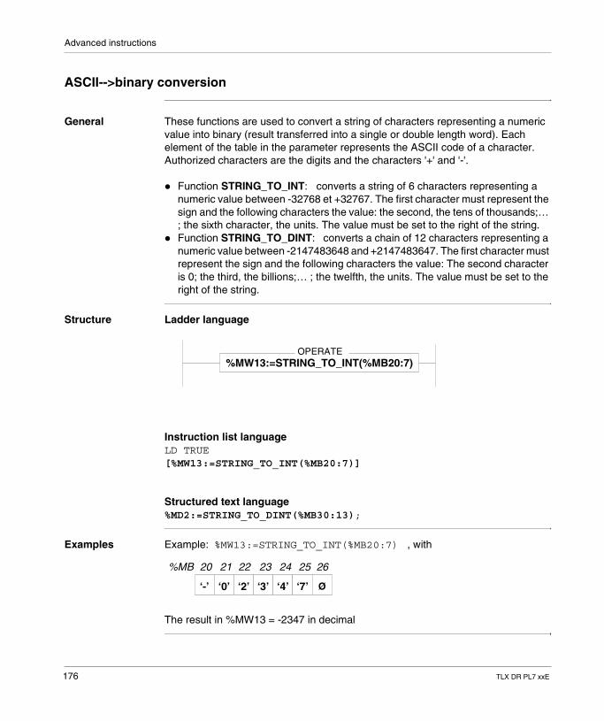
Advanced instructions
ASCII-->binary conversion
General These functions are used to convert a string of characters representing a numeric value into binary (result transferred into a single or double length word). Each element of the table in the parameter represents the ASCII code of a character. Authorized characters are the digits and the characters '+' and '-'.
� Function STRING_TO_INT: converts a string of 6 characters representing a numeric value between -32768 et +32767. The first character must represent the sign and the following characters the value: the second, the tens of thousands;… ; the sixth character, the units. The value must be set to the right of the string.
� Function STRING_TO_DINT: converts a chain of 12 characters representing a numeric value between -2147483648 and +2147483647. The first character must represent the sign and the following characters the value: The second character is 0; the third, the billions;… ; the twelfth, the units. The value must be set to the right of the string.
Structure Ladder language
Instruction list languageLD TRUE[%MW13:=STRING_TO_INT(%MB20:7)]
Structured text language%MD2:=STRING_TO_DINT(%MB30:13);
Examples Example: %MW13:=STRING_TO_INT(%MB20:7) , with
The result in %MW13 = -2347 in decimal
OPERATE%MW13:=STRING_TO_INT(%MB20:7)
%MB 20 21 22 23 24 25 26
‘-’ ‘0’ ‘2’ ‘3’ ‘4’ ‘7’ Ø
176 TLX DR PL7 xxE
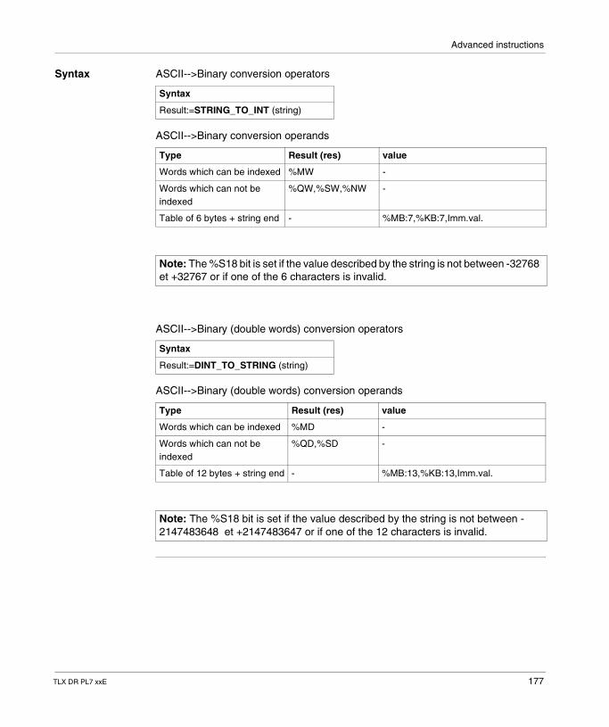
Advanced instructions
Syntax ASCII-->Binary conversion operators
ASCII-->Binary conversion operands
ASCII-->Binary (double words) conversion operators
ASCII-->Binary (double words) conversion operands
Syntax
Result:=STRING_TO_INT (string)
Type Result (res) value
Words which can be indexed %MW -
Words which can not be indexed
%QW,%SW,%NW -
Table of 6 bytes + string end - %MB:7,%KB:7,Imm.val.
Note: The %S18 bit is set if the value described by the string is not between -32768 et +32767 or if one of the 6 characters is invalid.
Syntax
Result:=DINT_TO_STRING (string)
Type Result (res) value
Words which can be indexed %MD -
Words which can not be indexed
%QD,%SD -
Table of 12 bytes + string end - %MB:13,%KB:13,Imm.val.
Note: The %S18 bit is set if the value described by the string is not between -2147483648 et +2147483647 or if one of the 12 characters is invalid.
TLX DR PL7 xxE 177
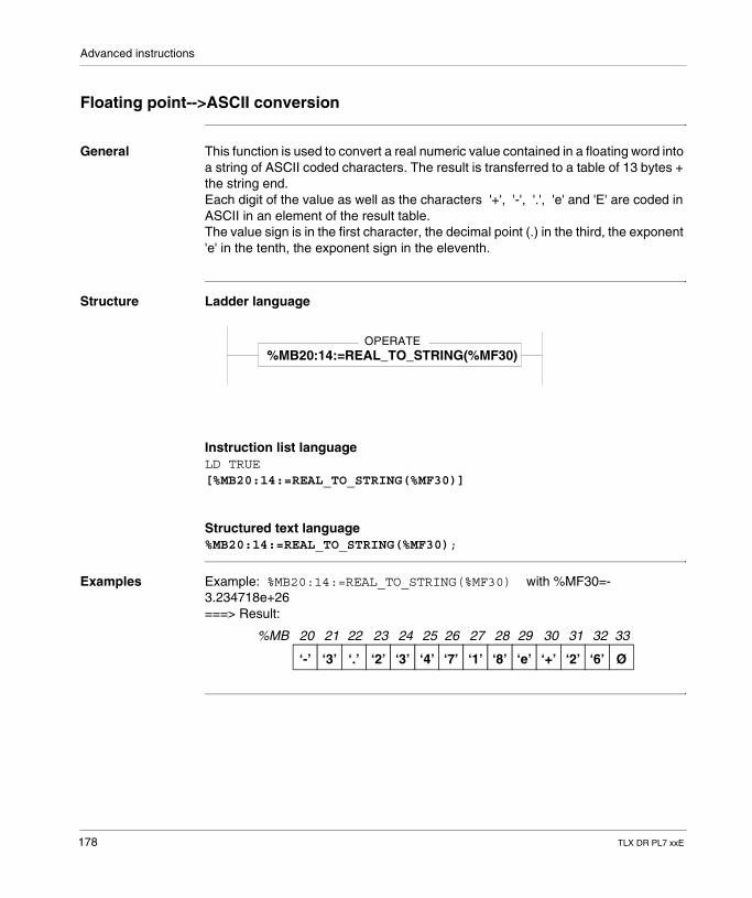
Advanced instructions
Floating point-->ASCII conversion
General This function is used to convert a real numeric value contained in a floating word into a string of ASCII coded characters. The result is transferred to a table of 13 bytes + the string end.Each digit of the value as well as the characters '+', '-', '.', 'e' and 'E' are coded in ASCII in an element of the result table.The value sign is in the first character, the decimal point (.) in the third, the exponent 'e' in the tenth, the exponent sign in the eleventh.
Structure Ladder language
Instruction list languageLD TRUE[%MB20:14:=REAL_TO_STRING(%MF30)]
Structured text language%MB20:14:=REAL_TO_STRING(%MF30);
Examples Example: %MB20:14:=REAL_TO_STRING(%MF30) with %MF30=- 3.234718e+26===> Result:
OPERATE%MB20:14:=REAL_TO_STRING(%MF30)
%MB 20 21 22 23 24 25 26
‘-’ ‘3’ ‘.’ ‘2’ ‘3’ ‘4’ ‘7’ ‘1’ ‘8’ ‘e’ ‘+’ ‘2’ ‘6’ Ø
27 28 29 30 31 32 33
178 TLX DR PL7 xxE
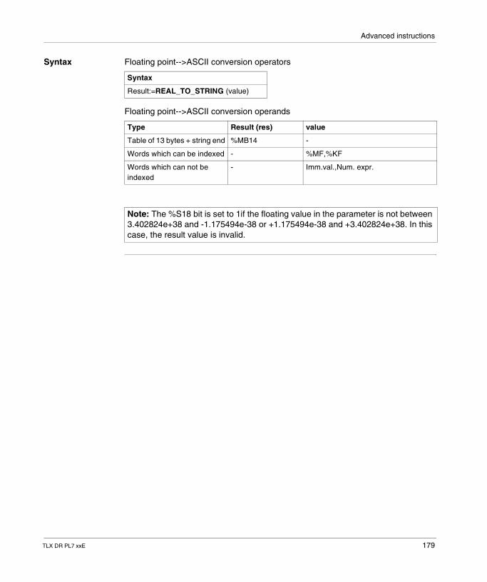
Advanced instructions
Syntax Floating point-->ASCII conversion operators
Floating point-->ASCII conversion operands
Syntax
Result:=REAL_TO_STRING (value)
Type Result (res) value
Table of 13 bytes + string end %MB14 -
Words which can be indexed - %MF,%KF
Words which can not be indexed
- Imm.val.,Num. expr.
Note: The %S18 bit is set to 1if the floating value in the parameter is not between 3.402824e+38 and -1.175494e-38 or +1.175494e-38 and +3.402824e+38. In this case, the result value is invalid.
TLX DR PL7 xxE 179
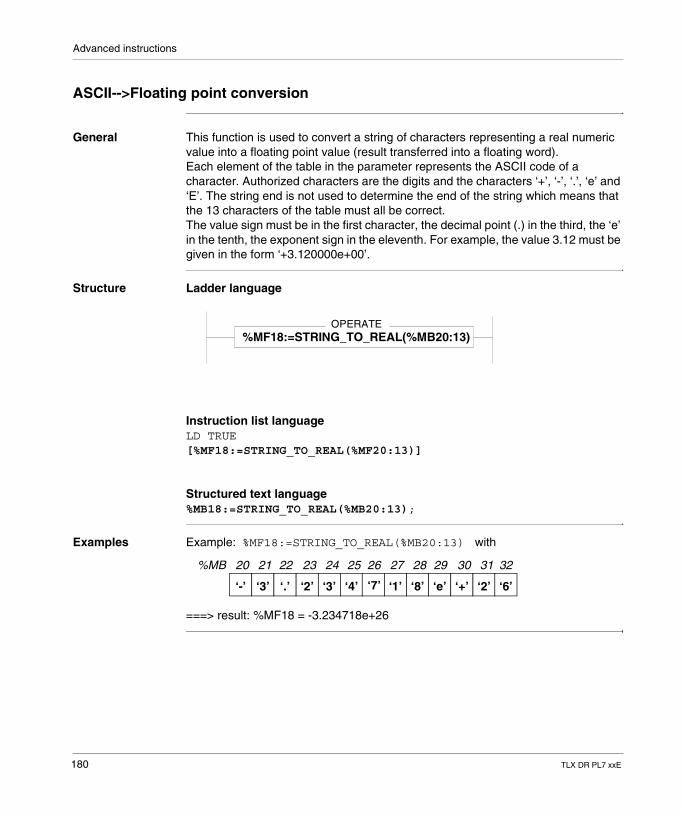
Advanced instructions
ASCII-->Floating point conversion
General This function is used to convert a string of characters representing a real numeric value into a floating point value (result transferred into a floating word).Each element of the table in the parameter represents the ASCII code of a character. Authorized characters are the digits and the characters ‘+’, ‘-’, ‘.’, ‘e’ and ‘E’. The string end is not used to determine the end of the string which means that the 13 characters of the table must all be correct.The value sign must be in the first character, the decimal point (.) in the third, the ‘e’ in the tenth, the exponent sign in the eleventh. For example, the value 3.12 must be given in the form ‘+3.120000e+00’.
Structure Ladder language
Instruction list languageLD TRUE[%MF18:=STRING_TO_REAL(%MF20:13)]
Structured text language%MB18:=STRING_TO_REAL(%MB20:13);
Examples Example: %MF18:=STRING_TO_REAL(%MB20:13) with
===> result: %MF18 = -3.234718e+26
OPERATE%MF18:=STRING_TO_REAL(%MB20:13)
%MB 20 21 22 23 24 25 26
‘-’ ‘3’ ‘.’ ‘2’ ‘3’ ‘4’ ‘7’ ‘1’ ‘8’ ‘e’ ‘+’ ‘2’ ‘6’
27 28 29 30 31 32
180 TLX DR PL7 xxE
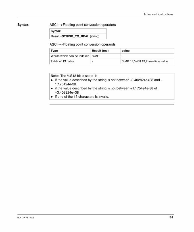
Advanced instructions
Syntax ASCII-->Floating point conversion operators
ASCII-->Floating point conversion operands
Syntax
Result:=STRING_TO_REAL (string)
Type Result (res) value
Words which can be indexed %MF -
Table of 13 bytes - %MB:13,%KB:13,Immediate value
Note: The %S18 bit is set to 1:� if the value described by the string is not between -3.402824e+38 and -
1.175494e-38� if the value described by the string is not between +1.175494e-38 et
+3.402824e+38� if one of the 13 characters is invalid.
TLX DR PL7 xxE 181
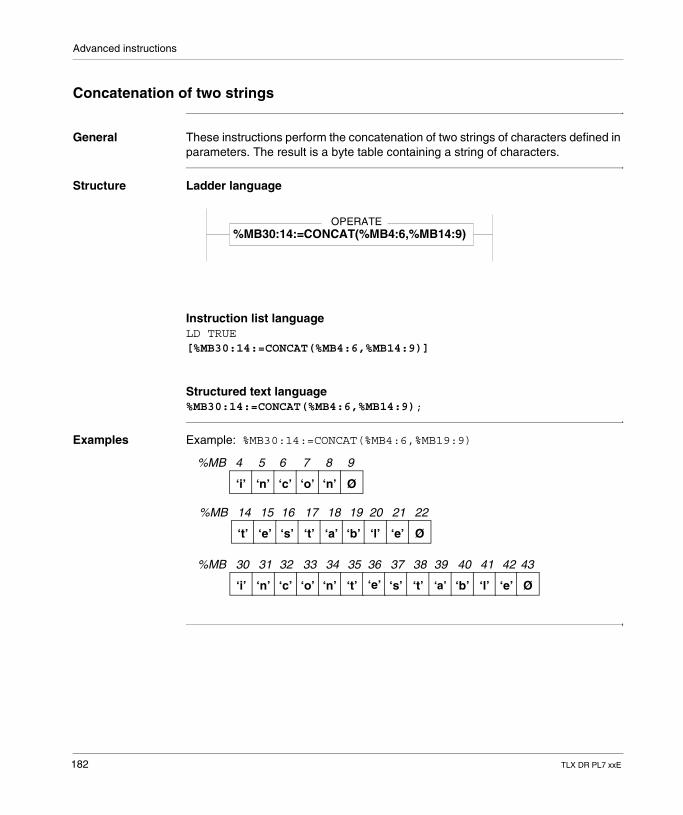
Advanced instructions
Concatenation of two strings
General These instructions perform the concatenation of two strings of characters defined in parameters. The result is a byte table containing a string of characters.
Structure Ladder language
Instruction list languageLD TRUE[%MB30:14:=CONCAT(%MB4:6,%MB14:9)]
Structured text language%MB30:14:=CONCAT(%MB4:6,%MB14:9);
Examples Example: %MB30:14:=CONCAT(%MB4:6,%MB19:9)
OPERATE%MB30:14:=CONCAT(%MB4:6,%MB14:9)
%MB 4 5 6 7 8 9
‘i’ ‘n’ ‘c’ ‘o’ ‘n’ Ø
%MB 14 15 16 17 18 19 20
‘t’ ‘e’ ‘s’ ‘t’ ‘a’ ‘b’ ‘l’ ‘e’ Ø
21 22
%MB 30 31 32 33 34 35 36
‘i’ ‘n’ ‘c’ ‘o’ ‘n’ ‘t’ ‘e’ ‘s’ ‘t’ ‘a’ ‘b’ ‘l’ ‘e’
37 38 39 40 41 42
Ø
43
182 TLX DR PL7 xxE
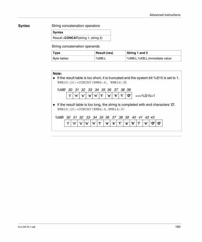
Advanced instructions
Syntax String concatenation operators
String concatenation operands
Syntax
Result:=CONCAT(string 1, string 2)
Type Result (res) String 1 and 2
Byte tables %MB:L %MB:L,%KB;L,Immediate value
Note: � If the result table is too short, it is truncated and the system bit %S15 is set to 1.
%MB30:10:=CONCAT(%MB4:6, %MB14:9)
� If the result table is too long, the string is completed with end characters 'Ø'. %MB30:15:=CONCAT(%MB4:6,%MB14:9)
%MB 30 31 32 33 34 35 36
‘i’ ‘n’ ‘c’ ‘o’ ‘n’ ‘t’ ‘e’ ‘s’ ‘t’
37 38
‘Ø’
38
==>%S15=1
%MB 30 31 32 33 34 35 36
‘i’ ‘n’ ‘c’ ‘o’ ‘n’ ‘t’ ‘e’ ‘s’ ‘t’ ‘a’ ‘b’ ‘l’ ‘e’
37 38 39 40 41 42
‘Ø’
43
‘Ø’
TLX DR PL7 xxE 183
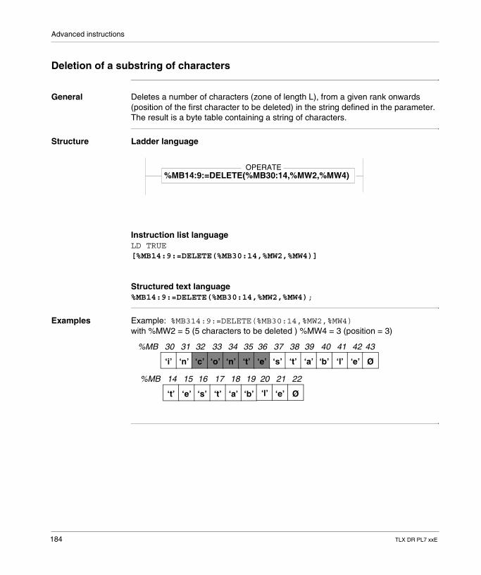
Advanced instructions
Deletion of a substring of characters
General Deletes a number of characters (zone of length L), from a given rank onwards (position of the first character to be deleted) in the string defined in the parameter. The result is a byte table containing a string of characters.
Structure Ladder language
Instruction list languageLD TRUE[%MB14:9:=DELETE(%MB30:14,%MW2,%MW4)]
Structured text language%MB14:9:=DELETE(%MB30:14,%MW2,%MW4);
Examples Example: %MB314:9:=DELETE(%MB30:14,%MW2,%MW4)with %MW2 = 5 (5 characters to be deleted ) %MW4 = 3 (position = 3)
OPERATE%MB14:9:=DELETE(%MB30:14,%MW2,%MW4)
%MB 14 15 16 17 18 19 20
‘t’ ‘e’ ‘s’ ‘t’ ‘a’ ‘b’ ‘l’ ‘e’ Ø
21 22
%MB 30 31 32 33 34 35 36
‘i’ ‘n’ ‘c’ ‘o’ ‘n’ ‘t’ ‘e’ ‘s’ ‘t’ ‘a’ ‘b’ ‘l’ ‘e’
37 38 39 40 41 42
Ø
43
184 TLX DR PL7 xxE

Advanced instructions
Syntax Operator for deletion of a substring of characters
Operands for deletion of a substring of characters
Syntax
Result:=DELETE(string 1, long, pos)
Type Result (res) String Long (length), Pos (position)
Byte tables %MB:L %MB:L,%KB;L,Immediate value
-
Indexable words - - %MW,%KW,%Xi.T
Non-indexable word
- - %IW,%QW,%SW,%NW, Imm.val., Num. Expr.
Note: Possibility of overlap between the parameters following the indexes of the PL7 objects:� Table containing the source string.� Table containing the result string.� Word containing the length to be deleted.� Word containing the position of the first character to be deleted.A negative length or position is interpreted as being equal to 0. The parameter position starts at the value 1, which corresponds to the first position in the string of characters.
TLX DR PL7 xxE 185
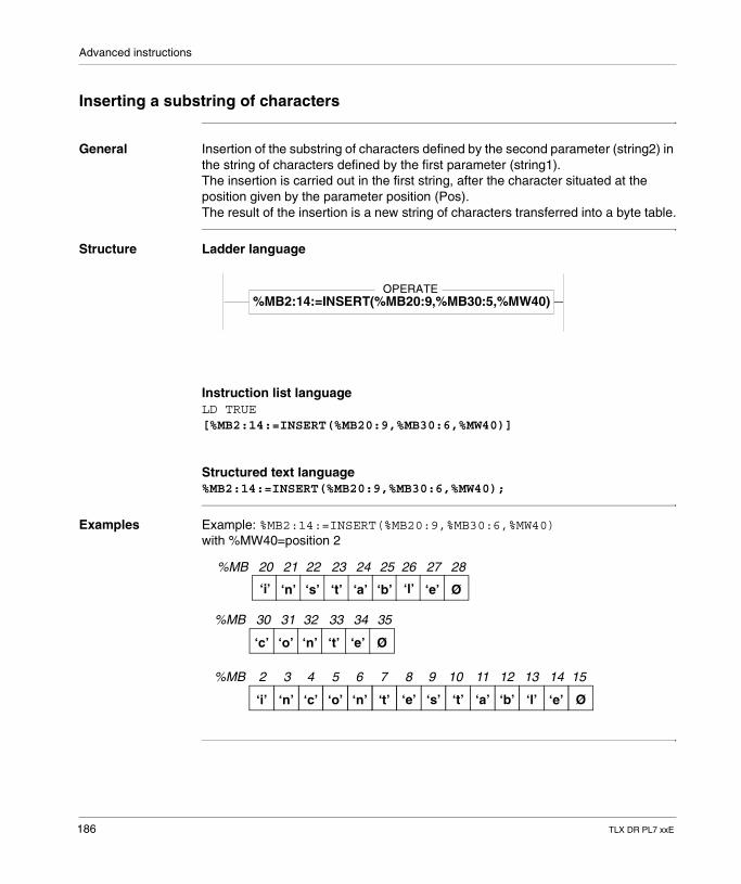
Advanced instructions
Inserting a substring of characters
General Insertion of the substring of characters defined by the second parameter (string2) in the string of characters defined by the first parameter (string1).The insertion is carried out in the first string, after the character situated at the position given by the parameter position (Pos).The result of the insertion is a new string of characters transferred into a byte table.
Structure Ladder language
Instruction list languageLD TRUE[%MB2:14:=INSERT(%MB20:9,%MB30:6,%MW40)]
Structured text language%MB2:14:=INSERT(%MB20:9,%MB30:6,%MW40);
Examples Example: %MB2:14:=INSERT(%MB20:9,%MB30:6,%MW40)with %MW40=position 2
OPERATE%MB2:14:=INSERT(%MB20:9,%MB30:5,%MW40)
%MB 20 21 22 23 24 25 26
‘i’ ‘n’ ‘s’ ‘t’ ‘a’ ‘b’ ‘l’ ‘e’ Ø
27 28
%MB 2 3 4 5 6 7 8
‘i’ ‘n’ ‘c’ ‘o’ ‘n’ ‘t’ ‘e’ ‘s’ ‘t’ ‘a’ ‘b’ ‘l’ ‘e’
9 10 11 12 13 14
Ø
15
%MB 30 31 32 33 34 35
‘c’ ‘o’ ‘n’ ‘t’ ‘e’ Ø
186 TLX DR PL7 xxE
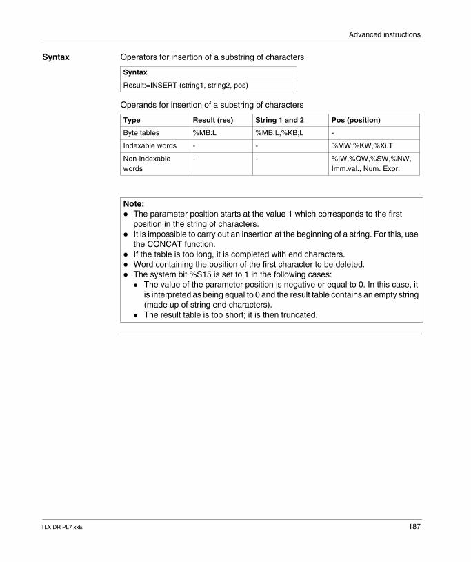
Advanced instructions
Syntax Operators for insertion of a substring of characters
Operands for insertion of a substring of characters
Syntax
Result:=INSERT (string1, string2, pos)
Type Result (res) String 1 and 2 Pos (position)
Byte tables %MB:L %MB:L,%KB;L -
Indexable words - - %MW,%KW,%Xi.T
Non-indexable words
- - %IW,%QW,%SW,%NW, Imm.val., Num. Expr.
Note: � The parameter position starts at the value 1 which corresponds to the first
position in the string of characters.� It is impossible to carry out an insertion at the beginning of a string. For this, use
the CONCAT function.� If the table is too long, it is completed with end characters.� Word containing the position of the first character to be deleted.� The system bit %S15 is set to 1 in the following cases:
� The value of the parameter position is negative or equal to 0. In this case, it is interpreted as being equal to 0 and the result table contains an empty string (made up of string end characters).
� The result table is too short; it is then truncated.
TLX DR PL7 xxE 187
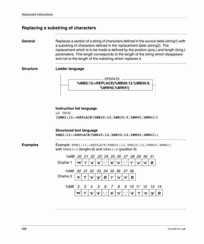
Advanced instructions
Replacing a substring of characters
General Replaces a section of a string of characters defined in the source table (string1) with a substring of characters defined in the replacement table (string2). The replacement which is to be made is defined by the position (pos.) and length (long.) parameters. This length corresponds to the length of the string which disappears and not to the length of the substring which replaces it.
Structure Ladder language
Instruction list languageLD TRUE[%MB2:13:=REPLACE(%MB20:12,%MB30:9,%MW40,%MW41)]
Structured text language%MB2:13:=REPLACE(%MB20:12,%MB30:12,%MW40,%MW41);
Examples Example: %MB2:13:=REPLACE(%MB20:12,%MB30:12,%MW40,%MW41)with %MW40=3 (length=3) and %MW41=9 (position 9)
OPERATE%MB2:13:=REPLACE(%MB20:12,%MB30:9,
%MW40,%MW41)
%MB 20 21 22 23 24 25 26
‘m’ ‘i’ ‘s’ ‘e’ ‘_’ ‘e’ ‘n’ ‘_’ ‘r’
27 28
%MB 2 3 4 5 6 7 8
‘m’ ‘i’ ‘s’ ‘e’ ‘_’ ‘e’ ‘n’ ‘_’ ‘s’ ‘t’ ‘o’ ‘p’ Ø
9 10 11 12 13 14
%MB 30 31 32 33 34 35
‘s’ ‘t’ ‘o’ ‘p’ Ø ‘r’
29 3130
3836 37
‘u’ ‘n’ Ø
‘u’ ‘n’ Ø
Chaîne 1
Chaîne 2
188 TLX DR PL7 xxE
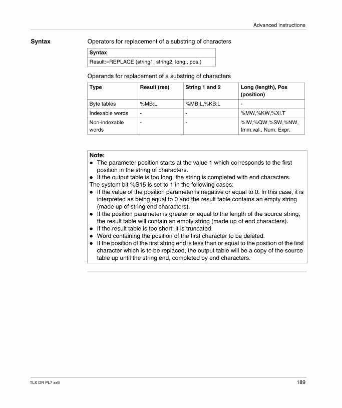
Advanced instructions
Syntax Operators for replacement of a substring of characters
Operands for replacement of a substring of characters
Syntax
Result:=REPLACE (string1, string2, long., pos.)
Type Result (res) String 1 and 2 Long (length), Pos (position)
Byte tables %MB:L %MB:L,%KB;L -
Indexable words - - %MW,%KW,%Xi.T
Non-indexable words
- - %IW,%QW,%SW,%NW, Imm.val., Num. Expr.
Note: � The parameter position starts at the value 1 which corresponds to the first
position in the string of characters.� If the output table is too long, the string is completed with end characters.The system bit %S15 is set to 1 in the following cases:� If the value of the position parameter is negative or equal to 0. In this case, it is
interpreted as being equal to 0 and the result table contains an empty string (made up of string end characters).
� If the position parameter is greater or equal to the length of the source string, the result table will contain an empty string (made up of end characters).
� If the result table is too short; it is truncated.� Word containing the position of the first character to be deleted.� If the position of the first string end is less than or equal to the position of the first
character which is to be replaced, the output table will be a copy of the source table up until the string end, completed by end characters.
TLX DR PL7 xxE 189
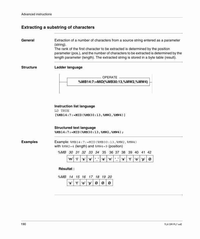
Advanced instructions
Extracting a substring of characters
General Extraction of a number of characters from a source string entered as a parameter (string).The rank of the first character to be extracted is determined by the position parameter (pos.), and the number of characters to be extracted is determined by the length parameter (length). The extracted string is stored in a byte table (result).
Structure Ladder language
Instruction list languageLD TRUE[%MB14:7:=MID(%MB30:13,%MW2,%MW4)]
Structured text language%MB14:7:=MID(%MB30:13,%MW2,%MW4);
Examples Example: %MB14:7:=MID(%MB30:13,%MW2,%MW4)with %MW2=4 (length) and %MW4=9 (position)
OPERATE
%MB14:7:=MID(%MB30:13,%MW2,%MW4)
%MB 30 31 32 33 34
‘m’ ‘i’ ‘s’ ‘e’ ‘_’ ‘e’ ‘n’ ‘_’ ‘s’ ‘t’ ‘o’ ‘p’ Ø
%MB 14 15 16 17 18 19
‘s’ ‘t’ ‘o’ ‘p’ Ø Ø
20
Ø
Résultat :
35 36 37 38 39 40 41 42
190 TLX DR PL7 xxE
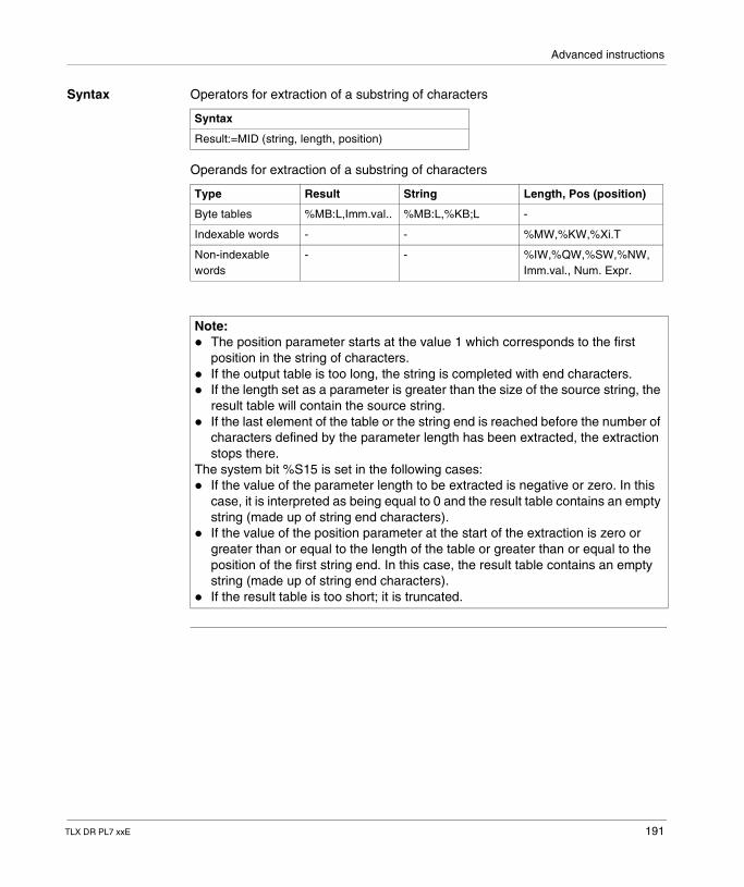
Advanced instructions
Syntax Operators for extraction of a substring of characters
Operands for extraction of a substring of characters
Syntax
Result:=MID (string, length, position)
Type Result String Length, Pos (position)
Byte tables %MB:L,Imm.val.. %MB:L,%KB;L -
Indexable words - - %MW,%KW,%Xi.T
Non-indexable words
- - %IW,%QW,%SW,%NW, Imm.val., Num. Expr.
Note: � The position parameter starts at the value 1 which corresponds to the first
position in the string of characters.� If the output table is too long, the string is completed with end characters.� If the length set as a parameter is greater than the size of the source string, the
result table will contain the source string.� If the last element of the table or the string end is reached before the number of
characters defined by the parameter length has been extracted, the extraction stops there.
The system bit %S15 is set in the following cases:� If the value of the parameter length to be extracted is negative or zero. In this
case, it is interpreted as being equal to 0 and the result table contains an empty string (made up of string end characters).
� If the value of the position parameter at the start of the extraction is zero or greater than or equal to the length of the table or greater than or equal to the position of the first string end. In this case, the result table contains an empty string (made up of string end characters).
� If the result table is too short; it is truncated.
TLX DR PL7 xxE 191
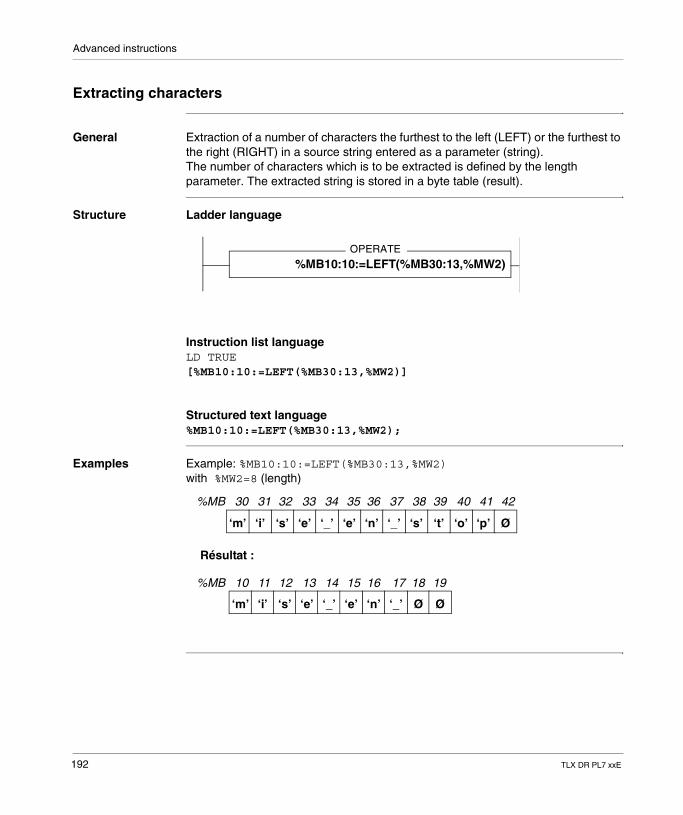
Advanced instructions
Extracting characters
General Extraction of a number of characters the furthest to the left (LEFT) or the furthest to the right (RIGHT) in a source string entered as a parameter (string).The number of characters which is to be extracted is defined by the length parameter. The extracted string is stored in a byte table (result).
Structure Ladder language
Instruction list languageLD TRUE[%MB10:10:=LEFT(%MB30:13,%MW2)]
Structured text language%MB10:10:=LEFT(%MB30:13,%MW2);
Examples Example: %MB10:10:=LEFT(%MB30:13,%MW2)with %MW2=8 (length)
OPERATE
%MB10:10:=LEFT(%MB30:13,%MW2)
%MB 30 31 32 33 34 35 36
‘m’ ‘i’ ‘s’ ‘e’ ‘_’ ‘e’ ‘n’ ‘_’ ‘s’ ‘t’ ‘o’ ‘p’ Ø
37 38 39 40 41 42
%MB 10 11 12 13 14 15
‘m’ ‘i’ ‘s’ ‘e’ ‘_’ ‘e’
17
Ø
Résultat :
16 18 19
Ø‘_’‘n’
192 TLX DR PL7 xxE
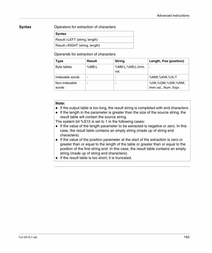
Advanced instructions
Syntax Operators for extraction of characters
Operands for extraction of characters
Syntax
Result:=LEFT (string, length)
Result:=RIGHT (string, length)
Type Result String Length, Pos (position)
Byte tables %MB:L %MB:L,%KB;L,Imm. val.
-
Indexable words - - %MW,%KW,%Xi.T
Non-indexable words
- - %IW,%QW,%SW,%NW, Imm.val., Num. Expr.
Note: � If the output table is too long, the result string is completed with end characters.� If the length in the parameter is greater than the size of the source string, the
result table will contain the source string.The system bit %S15 is set to 1 in the following cases:� If the value of the length parameter to be extracted is negative or zero. In this
case, the result table contains an empty string (made up of string end characters).
� If the value of the position parameter at the start of the extraction is zero or greater than or equal to the length of the table or greater than or equal to the position of the first string end. In this case, the result table contains an empty string (made up of string end characters).
� If the result table is too short; it is truncated.
TLX DR PL7 xxE 193
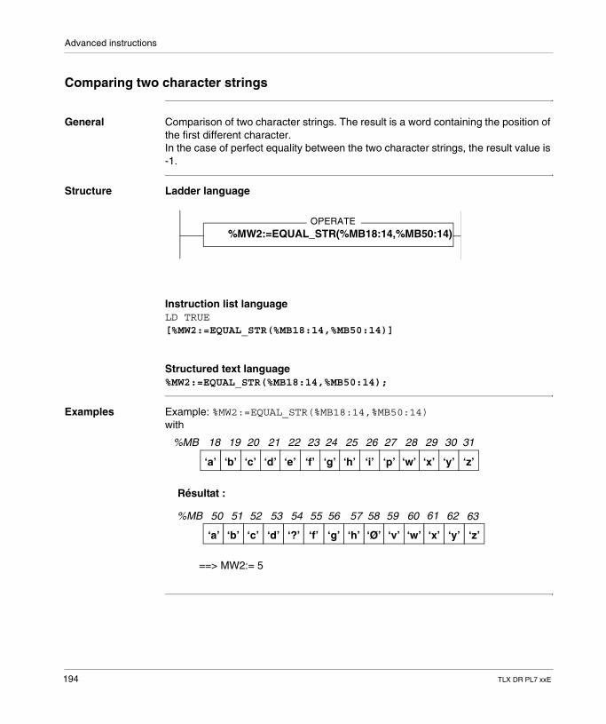
Advanced instructions
Comparing two character strings
General Comparison of two character strings. The result is a word containing the position of the first different character.In the case of perfect equality between the two character strings, the result value is -1.
Structure Ladder language
Instruction list languageLD TRUE[%MW2:=EQUAL_STR(%MB18:14,%MB50:14)]
Structured text language%MW2:=EQUAL_STR(%MB18:14,%MB50:14);
Examples Example: %MW2:=EQUAL_STR(%MB18:14,%MB50:14)with
OPERATE%MW2:=EQUAL_STR(%MB18:14,%MB50:14)
%MB 18 19 20 21 22 23 24
‘a’ ‘b’ ‘c’ ‘d’ ‘e’ ‘f’ ‘g’ ‘h’ ‘i’ ‘p’ ‘w’ ‘x’ ‘y’
25 26 27 28 29 30
%MB 50 51 52 53 54 55
‘a’ ‘b’ ‘c’ ‘d’ ‘?’ ‘f’
57
‘Ø’
Résultat :
56 58 59
‘Ø’‘h’‘g’
31
‘z’
60 61 62 63
‘v’ ‘x’‘w’ ‘y’ ‘z’
==> MW2:= 5
194 TLX DR PL7 xxE
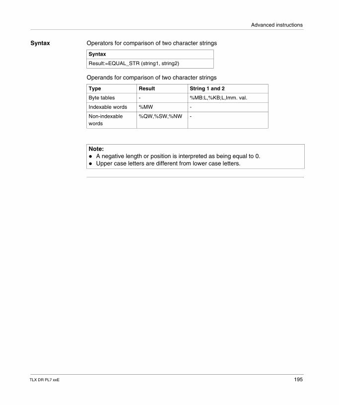
Advanced instructions
Syntax Operators for comparison of two character strings
Operands for comparison of two character strings
Syntax
Result:=EQUAL_STR (string1, string2)
Type Result String 1 and 2
Byte tables - %MB:L,%KB;L,Imm. val.
Indexable words %MW -
Non-indexable words
%QW,%SW,%NW -
Note: � A negative length or position is interpreted as being equal to 0.� Upper case letters are different from lower case letters.
TLX DR PL7 xxE 195
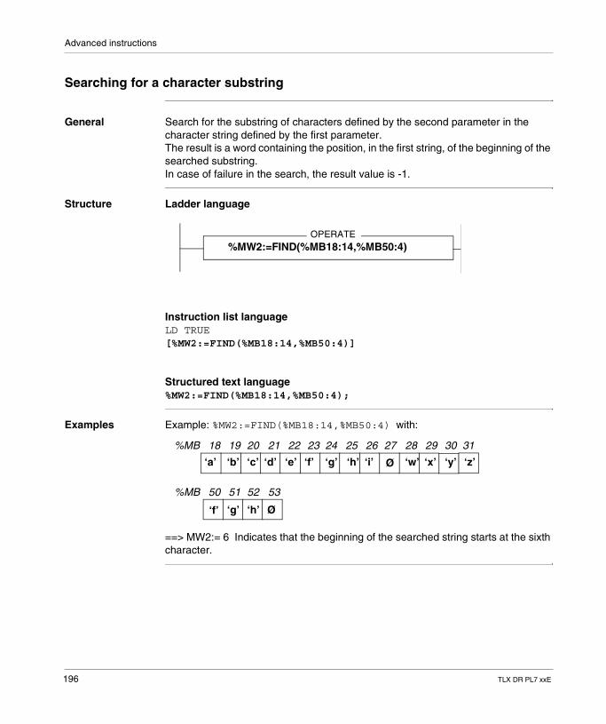
Advanced instructions
Searching for a character substring
General Search for the substring of characters defined by the second parameter in the character string defined by the first parameter.The result is a word containing the position, in the first string, of the beginning of the searched substring.In case of failure in the search, the result value is -1.
Structure Ladder language
Instruction list languageLD TRUE[%MW2:=FIND(%MB18:14,%MB50:4)]
Structured text language%MW2:=FIND(%MB18:14,%MB50:4);
Examples Example: %MW2:=FIND(%MB18:14,%MB50:4) with:
==> MW2:= 6 Indicates that the beginning of the searched string starts at the sixth character.
OPERATE%MW2:=FIND(%MB18:14,%MB50:4)
%MB 18 19 20 21 22 23 24
‘a’ ‘b’ ‘c’ ‘d’ ‘e’ ‘f’ ‘g’ ‘h’ ‘i’ Ø ‘w’ ‘x’ ‘y’
25 26 27 28 29 30
%MB 50 51 52 53
‘f’ ‘g’ ‘h’ Ø
31
‘z’
196 TLX DR PL7 xxE

Advanced instructions
Syntax Search operators for character substrings
Search operands for characters substrings
Syntax
Result:=FIND (string1, string2)
Type Result String 1 and 2
Indexable words %MW -
Non-indexable words
%QW,%SW,%NW -
Byte tables - %MB:L,%KB;L,Imm. val.
Note: A negative length or position is interpreted as being equal to 0.
TLX DR PL7 xxE 197
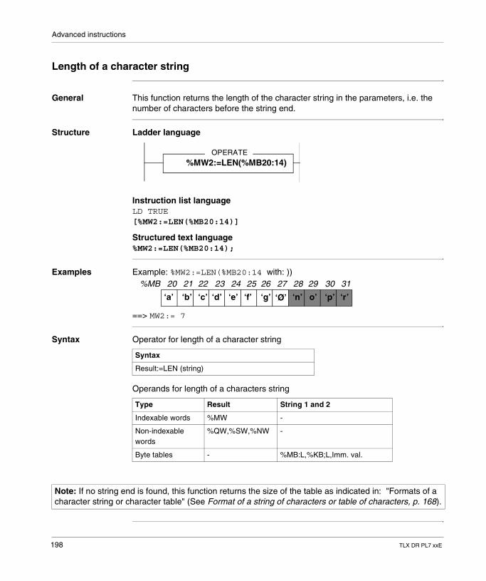
Advanced instructions
Length of a character string
General This function returns the length of the character string in the parameters, i.e. the number of characters before the string end.
Structure Ladder language
Instruction list languageLD TRUE[%MW2:=LEN(%MB20:14)]
Structured text language%MW2:=LEN(%MB20:14);
Examples Example: %MW2:=LEN(%MB20:14 with: ))
==> MW2:= 7
Syntax Operator for length of a character string
Operands for length of a characters string
OPERATE%MW2:=LEN(%MB20:14)
%MB 20 21 22 23 24 25 26
‘a’ ‘b’ ‘c’ ‘d’ ‘e’ ‘f’ ‘g’ ‘Ø’ ‘n’ o’ ‘p’ ‘r’
27 28 29 30 31
Syntax
Result:=LEN (string)
Type Result String 1 and 2
Indexable words %MW -
Non-indexable words
%QW,%SW,%NW -
Byte tables - %MB:L,%KB;L,Imm. val.
Note: If no string end is found, this function returns the size of the table as indicated in: "Formats of a character string or character table" (See Format of a string of characters or table of characters, p. 168).
198 TLX DR PL7 xxE
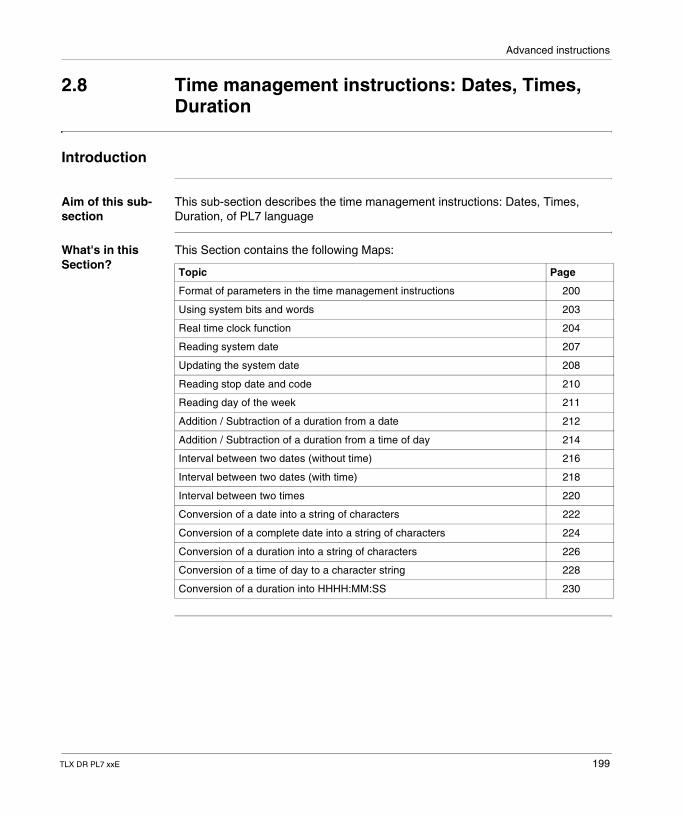
Advanced instructions
2.8 Time management instructions: Dates, Times, Duration
Introduction
Aim of this sub-section
This sub-section describes the time management instructions: Dates, Times, Duration, of PL7 language
What's in this Section?
This Section contains the following Maps:
Topic Page
Format of parameters in the time management instructions 200
Using system bits and words 203
Real time clock function 204
Reading system date 207
Updating the system date 208
Reading stop date and code 210
Reading day of the week 211
Addition / Subtraction of a duration from a date 212
Addition / Subtraction of a duration from a time of day 214
Interval between two dates (without time) 216
Interval between two dates (with time) 218
Interval between two times 220
Conversion of a date into a string of characters 222
Conversion of a complete date into a string of characters 224
Conversion of a duration into a string of characters 226
Conversion of a time of day to a character string 228
Conversion of a duration into HHHH:MM:SS 230
TLX DR PL7 xxE 199
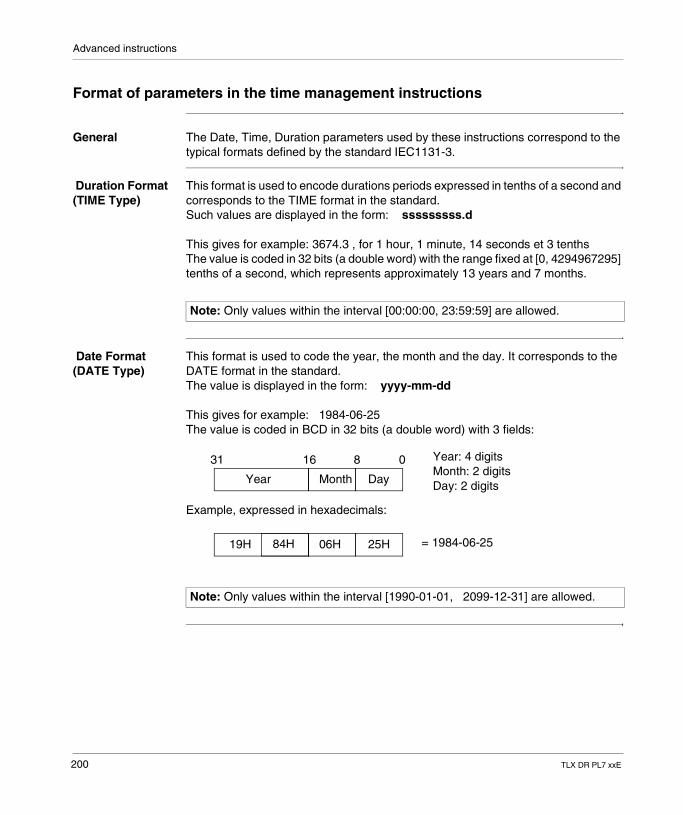
Advanced instructions
Format of parameters in the time management instructions
General The Date, Time, Duration parameters used by these instructions correspond to the typical formats defined by the standard IEC1131-3.
Duration Format (TIME Type)
This format is used to encode durations periods expressed in tenths of a second and corresponds to the TIME format in the standard.Such values are displayed in the form: sssssssss.d
This gives for example: 3674.3 , for 1 hour, 1 minute, 14 seconds et 3 tenthsThe value is coded in 32 bits (a double word) with the range fixed at [0, 4294967295] tenths of a second, which represents approximately 13 years and 7 months.
Date Format (DATE Type)
This format is used to code the year, the month and the day. It corresponds to the DATE format in the standard.The value is displayed in the form: yyyy-mm-dd
This gives for example: 1984-06-25The value is coded in BCD in 32 bits (a double word) with 3 fields:
Example, expressed in hexadecimals:
Note: Only values within the interval [00:00:00, 23:59:59] are allowed.
Note: Only values within the interval [1990-01-01, 2099-12-31] are allowed.
Year Month Day
31 16 8 0 Year: 4 digitsMonth: 2 digitsDay: 2 digits
19H 06H 25H = 1984-06-2584H
200 TLX DR PL7 xxE
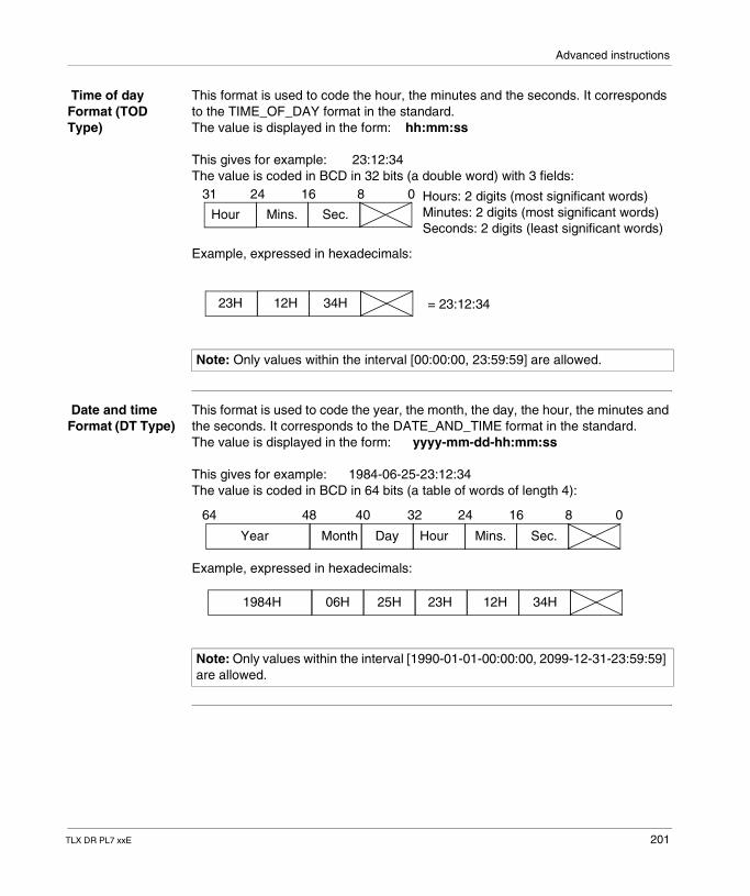
Advanced instructions
Time of day Format (TOD Type)
This format is used to code the hour, the minutes and the seconds. It corresponds to the TIME_OF_DAY format in the standard.The value is displayed in the form: hh:mm:ss
This gives for example: 23:12:34The value is coded in BCD in 32 bits (a double word) with 3 fields:
Example, expressed in hexadecimals:
Date and time Format (DT Type)
This format is used to code the year, the month, the day, the hour, the minutes and the seconds. It corresponds to the DATE_AND_TIME format in the standard.The value is displayed in the form: yyyy-mm-dd-hh:mm:ss
This gives for example: 1984-06-25-23:12:34The value is coded in BCD in 64 bits (a table of words of length 4):
Example, expressed in hexadecimals:
Note: Only values within the interval [00:00:00, 23:59:59] are allowed.
8 01624
Hour Mins. Sec.
31 Hours: 2 digits (most significant words)Minutes: 2 digits (most significant words)Seconds: 2 digits (least significant words)
23H 12H 34H = 23:12:34
Note: Only values within the interval [1990-01-01-00:00:00, 2099-12-31-23:59:59] are allowed.
Year Month Day
64 8 0162448 40
Hour Mins. Sec.
32
1984H 06H 25H 23H 12H 34H
TLX DR PL7 xxE 201
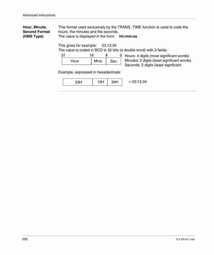
Advanced instructions
Hour, Minute, Second Format (HMS Type)
This format used exclusively by the TRANS_TIME function is used to code the hours, the minutes and the seconds.The value is displayed in the form: hh:mm:ss
This gives for example: 23:12:34The value is coded in BCD in 32 bits (a double word) with 3 fields:
Example, expressed in hexadecimals:
8 016
Hour Mins. Sec.
31 Hours: 4 digits (most significant words)Minutes: 2 digits (least significant words)Seconds: 2 digits (least significant
23H 12H 34H = 23:12:34
202 TLX DR PL7 xxE
Advanced instructions
Using system bits and words
System bit %S17 The system bit %S17 is set in the following cases:� Result of an operation outside the range of permitted values� An input parameter cannot be interpreted and is not coherent with the desired
format (DATE, DT or TOD)� Operation on a Time of Day (TOD) format involving a change of day� Real time clock access conflict
System bit %S15 The system bit %S15 is set to 1 when a string is being written in a table, when this string is longer than the size of the table.
System words System words:� %SD18: absolute time counter is also used to calculate durations (incremented
every 1/10 of a second by the system)� %SW49 à %SW53 (See Description of system words %SW48 to %SW59, p. 302)
can also be used to display dates
TLX DR PL7 xxE 203
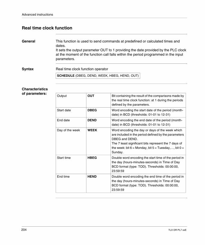
Advanced instructions
Real time clock function
General This function is used to send commands at predefined or calculated times and dates.It sets the output parameter OUT to 1 providing the date provided by the PLC clock at the moment of the function call falls within the period programmed in the input parameters.
Syntax Real time clock function operator
Characteristics of parameters:
SCHEDULE (DBEG, DEND, WEEK, HBEG, HEND, OUT)
Output OUT Bit containing the result of the comparisons made by the real time clock function: at 1 during the periods defined by the parameters.
Start date DBEG Word encoding the start date of the period (month-date) in BCD (thresholds: 01-01 to 12-31)
End date DEND Word encoding the end date of the period (month-date) in BCD (thresholds: 01-01 to 12-31)
Day of the week WEEK Word encoding the day or days of the week which are included in the period defined by the parameters DBEG and DEND.The 7 least significant bits represent the 7 days of the week: bit 6 = Monday, bit 5 = Tuesday,…, bit 0 = Sunday.
Start time HBEG Double word encoding the start time of the period in the day (hours-minutes-seconds) in Time of Day BCD format (type: TOD). Thresholds: 00:00:00, 23:59:59
End time HEND Double word encoding the end time of the period in the day (hours-minutes-seconds) in Time of Day BCD format (type: TOD). Thresholds: 00:00:00, 23:59:59
204 TLX DR PL7 xxE
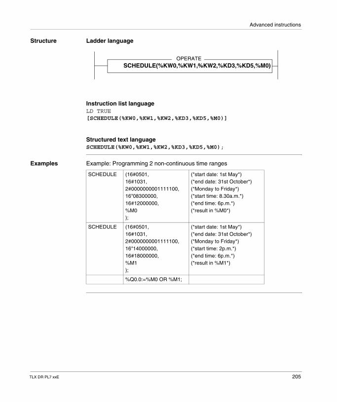
Advanced instructions
Structure Ladder language
Instruction list languageLD TRUE[SCHEDULE(%KW0,%KW1,%KW2,%KD3,%KD5,%M0)]
Structured text languageSCHEDULE(%KW0,%KW1,%KW2,%KD3,%KD5,%M0);
Examples Example: Programming 2 non-continuous time ranges
OPERATESCHEDULE(%KW0,%KW1,%KW2,%KD3,%KD5,%M0)
SCHEDULE (16#0501,16#1031,2#0000000001111100,16"08300000,16#12000000,%M0);
(*start date: 1st May*)(*end date: 31st October*)(*Monday to Friday*)(*start time: 8.30a.m.*)(*end time: 6p.m.*)(*result in %M0*)
SCHEDULE (16#0501,16#1031,2#0000000001111100,16"14000000,16#18000000,%M1);
(*start date: 1st May*)(*end date: 31st October*)(*Monday to Friday*)(*start time: 2p.m.*)(*end time: 6p.m.*)(*result in %M1*)
%Q0.0:=%M0 OR %M1;
TLX DR PL7 xxE 205
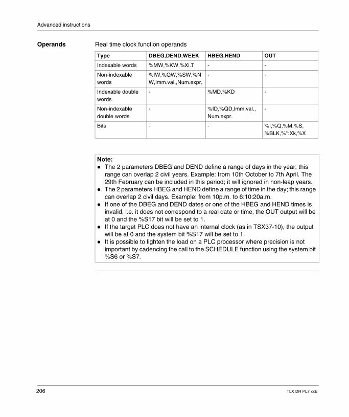
Advanced instructions
Operands Real time clock function operands
Type DBEG,DEND,WEEK HBEG,HEND OUT
Indexable words %MW,%KW,%Xi.T - -
Non-indexable words
%IW,%QW,%SW,%NW,Imm.val.,Num.expr.
- -
Indexable double words
- %MD,%KD -
Non-indexable double words
- %ID,%QD,Imm.val., Num.expr.
-
Bits - - %I,%Q,%M,%S, %BLK,%*:Xk,%X
Note: � The 2 parameters DBEG and DEND define a range of days in the year; this
range can overlap 2 civil years. Example: from 10th October to 7th April. The 29th February can be included in this period; it will ignored in non-leap years.
� The 2 parameters HBEG and HEND define a range of time in the day; this range can overlap 2 civil days. Example: from 10p.m. to 6:10:20a.m.
� If one of the DBEG and DEND dates or one of the HBEG and HEND times is invalid, i.e. it does not correspond to a real date or time, the OUT output will be at 0 and the %S17 bit will be set to 1.
� If the target PLC does not have an internal clock (as in TSX37-10), the output will be at 0 and the system bit %S17 will be set to 1.
� It is possible to lighten the load on a PLC processor where precision is not important by cadencing the call to the SCHEDULE function using the system bit %S6 or %S7.
206 TLX DR PL7 xxE
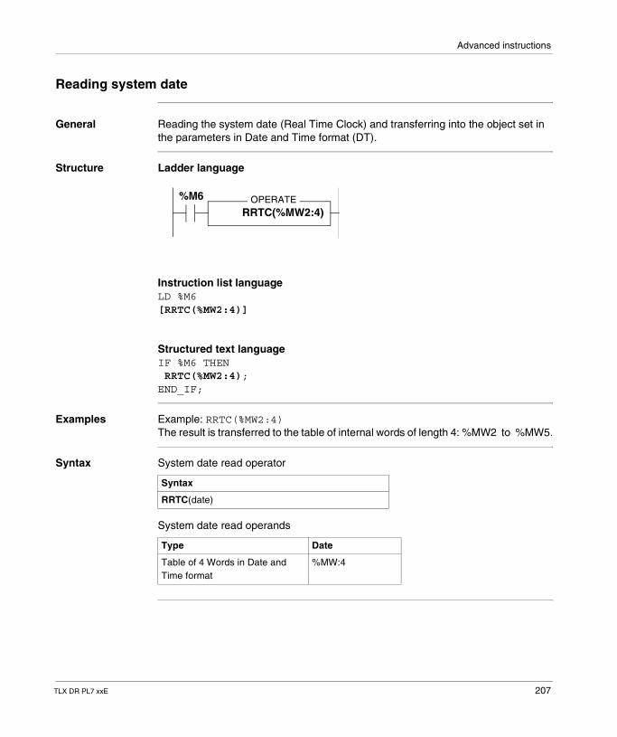
Advanced instructions
Reading system date
General Reading the system date (Real Time Clock) and transferring into the object set in the parameters in Date and Time format (DT).
Structure Ladder language
Instruction list languageLD %M6[RRTC(%MW2:4)]
Structured text languageIF %M6 THEN RRTC(%MW2:4);END_IF;
Examples Example: RRTC(%MW2:4)The result is transferred to the table of internal words of length 4: %MW2 to %MW5.
Syntax System date read operator
System date read operands
OPERATERRTC(%MW2:4)
%M6
Syntax
RRTC(date)
Type Date
Table of 4 Words in Date and Time format
%MW:4
TLX DR PL7 xxE 207
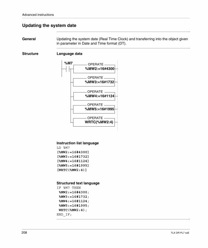
Advanced instructions
Updating the system date
General Updating the system date (Real Time Clock) and transferring into the object given in parameter in Date and Time format (DT).
Structure Language data
Instruction list languageLD %M7[%MW2:=16#4300][%MW3:=16#1732][%MW4:=16#1124][%MW5:=16#1995][WRTC(%MW2:4)]
Structured text languageIF %M7 THEN %MW2:=16#4300; %MW3:=16#1732; %MW4:=16#1124; %MW5:=16#1995; WRTC(%MW2:4);END_IF;
OPERATE%MW2:=16#4300
OPERATE%MW3:=16#1732
OPERATE%MW4:=16#1124
WRTC(%MW2:4)
%MW5:=16#1995
%M7
OPERATE
OPERATE
208 TLX DR PL7 xxE
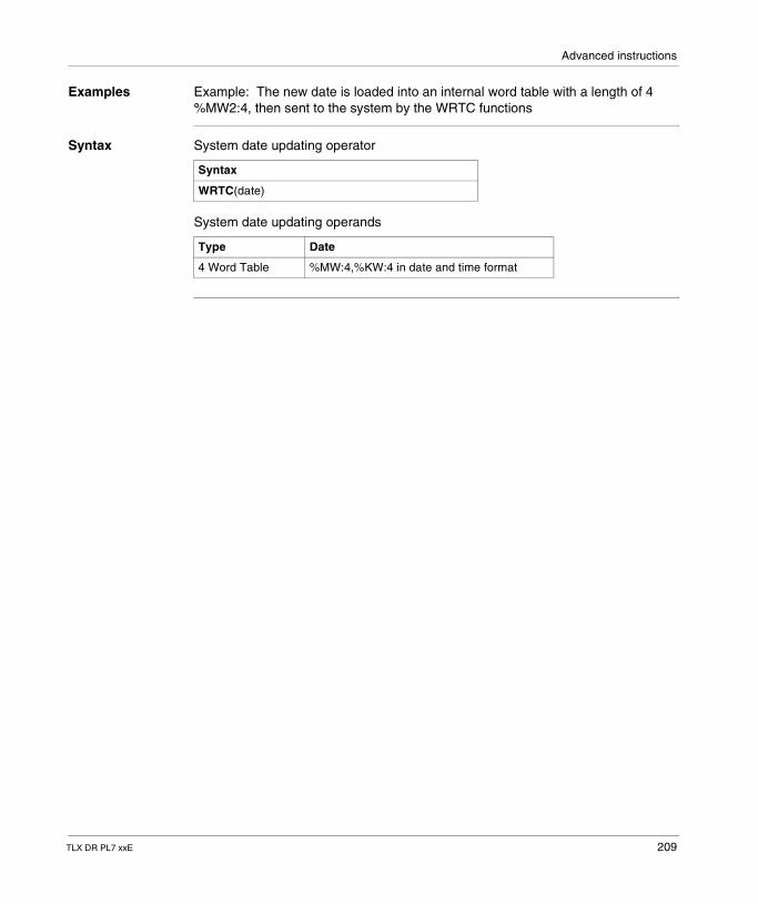
Advanced instructions
Examples Example: The new date is loaded into an internal word table with a length of 4 %MW2:4, then sent to the system by the WRTC functions
Syntax System date updating operator
System date updating operands
Syntax
WRTC(date)
Type Date
4 Word Table %MW:4,%KW:4 in date and time format
TLX DR PL7 xxE 209
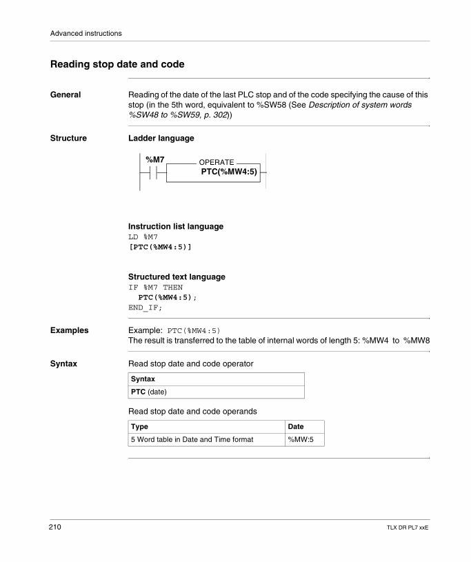
Advanced instructions
Reading stop date and code
General Reading of the date of the last PLC stop and of the code specifying the cause of this stop (in the 5th word, equivalent to %SW58 (See Description of system words %SW48 to %SW59, p. 302))
Structure Ladder language
Instruction list languageLD %M7[PTC(%MW4:5)]
Structured text languageIF %M7 THEN PTC(%MW4:5);END_IF;
Examples Example: PTC(%MW4:5)The result is transferred to the table of internal words of length 5: %MW4 to %MW8
Syntax Read stop date and code operator
Read stop date and code operands
OPERATEPTC(%MW4:5)
%M7
Syntax
PTC (date)
Type Date
5 Word table in Date and Time format %MW:5
210 TLX DR PL7 xxE
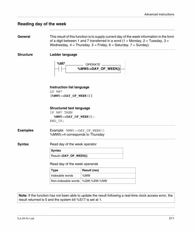
Advanced instructions
Reading day of the week
General This result of this function is to supply current day of the week information in the form of a digit between 1 and 7 transferred in a word (1 = Monday, 2 = Tuesday, 3 = Wednesday, 4 = Thursday. 5 = Friday, 6 = Saturday, 7 = Sunday).
Structure Ladder language
Instruction list languageLD %M7[%MW5:=DAY_OF_WEEK()]
Structured text languageIF %M7 THEN %MW5:=DAY_OF_WEEK();END_IF;
Examples Example: %MW5:=DAY_OF_WEEK()%MW5:=4 corresponds to Thursday
Syntax Read day of the week operator
Read day of the week operands
OPERATE%MW5:=DAY_OF_WEEK()
%M7
Syntax
Result:=DAY_OF_WEEK()
Type Result (res)
Indexable words %MW
Non-indexable words %QW,%SW,%NW
Note: If the function has not been able to update the result following a real-time clock access error, the result returned is 0 and the system bit %S17 is set at 1.
TLX DR PL7 xxE 211
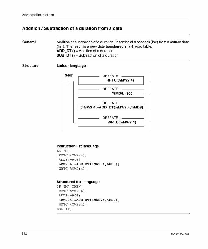
Advanced instructions
Addition / Subtraction of a duration from a date
General Addition or subtraction of a duration (in tenths of a second) (In2) from a source date (In1). The result is a new date transferred in a 4 word table.ADD_DT () = Addition of a durationSUB_DT () = Subtraction of a duration
Structure Ladder language
Instruction list languageLD %M7[RRTC(%MW2:4)][%MD8:=906][%MW2:4:=ADD_DT(%MW2:4,%MD8)][WRTC(%MW2:4)]
Structured text languageIF %M7 THEN RRTC(%MW2:4); %MD8:=906; %MW2:4:=ADD_DT(%MW2:4,%MD8); WRTC(%MW2:4);END_IF;
OPERATERRTC(%MW2:4)
%M7
OPERATE
OPERATE
OPERATE
%MD8:=906
%MW2:4:=ADD_DT(%MW2:4,%MD8)
WRTC(%MW2:4)
212 TLX DR PL7 xxE
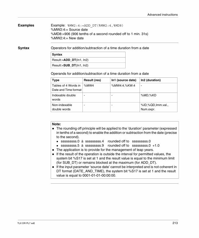
Advanced instructions
Examples Example: %MW2:4:=ADD_DT(%MW2:4,%MD8)%MW2:4:= Source date%MD8:=906 (906 tenths of a second rounded off to 1 min. 31s)%MW2:4:= New date
Syntax Operators for addition/subtraction of a time duration from a date
Operands for addition/subtraction of a time duration from a date
Syntax
Result:=ADD_DT(In1, In2)
Result:=SUB_DT(In1, In2)
Type Result (res) In1 (source date) In2 (duration)
Tables of 4 Words in Date and Time format
%MW4 %MW4:4,%KW:4 -
Indexable double words
- - %MD,%KD
Non-indexable double words
- - %ID,%QD,Imm.val., Num.expr.
Note: � The rounding off principle will be applied to the ‘duration’ parameter (expressed
in tenths of a second) to enable the addition or subtraction from the date (precise to the second).� sssssssss.0 à sssssssss.4 rounded off to sssssssss.0� sssssssss.5 à sssssssss.9 rounded off to sssssssss.0 +1.0
� The application is to provide for the management of leap years.� If the result of the operation is outside the interval for permitted values, the
system bit %S17 is set at 1 and the result value is equal to the minimum limit (for SUB_DT) or remains blocked at the maximum (for ADD_DT).
� If the input parameter ‘source date’ cannot be interpreted and is not coherent in DT format (DATE_AND_TIME), the system bit %S17 is set at 1 and the result value is equal to 0001-01-01-00:00:00.
TLX DR PL7 xxE 213
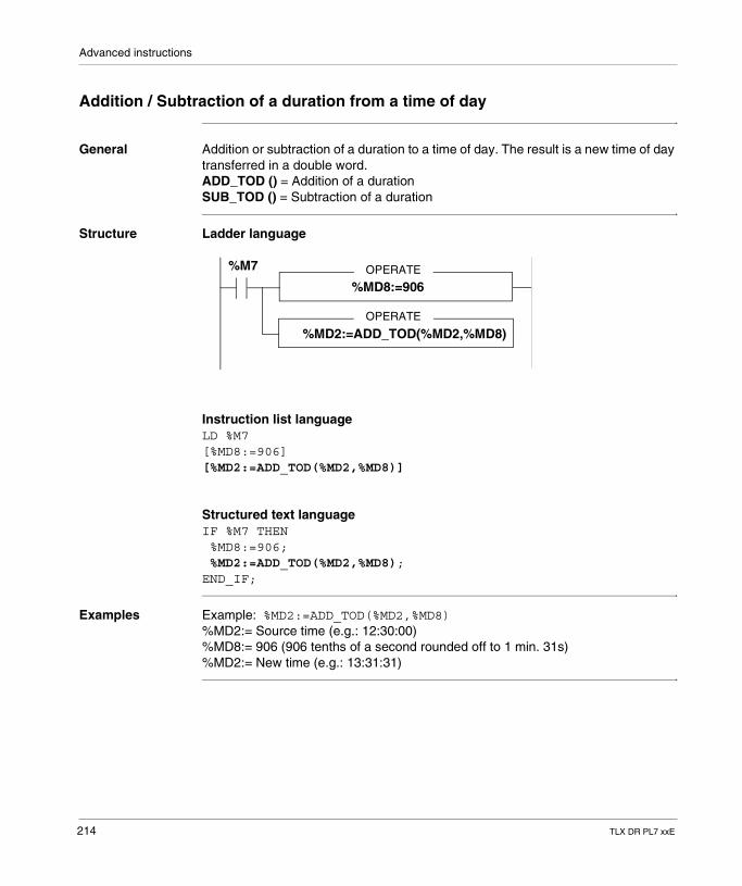
Advanced instructions
Addition / Subtraction of a duration from a time of day
General Addition or subtraction of a duration to a time of day. The result is a new time of day transferred in a double word.ADD_TOD () = Addition of a durationSUB_TOD () = Subtraction of a duration
Structure Ladder language
Instruction list languageLD %M7[%MD8:=906][%MD2:=ADD_TOD(%MD2,%MD8)]
Structured text languageIF %M7 THEN %MD8:=906; %MD2:=ADD_TOD(%MD2,%MD8);END_IF;
Examples Example: %MD2:=ADD_TOD(%MD2,%MD8)%MD2:= Source time (e.g.: 12:30:00)%MD8:= 906 (906 tenths of a second rounded off to 1 min. 31s)%MD2:= New time (e.g.: 13:31:31)
OPERATE
%MD2:=ADD_TOD(%MD2,%MD8)
%M7
OPERATE
%MD8:=906
214 TLX DR PL7 xxE
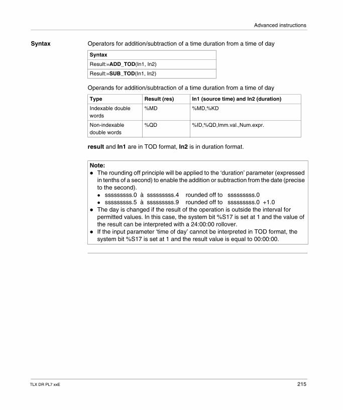
Advanced instructions
Syntax Operators for addition/subtraction of a time duration from a time of day
Operands for addition/subtraction of a time duration from a time of day
result and In1 are in TOD format, In2 is in duration format.
Syntax
Result:=ADD_TOD(In1, In2)
Result:=SUB_TOD(In1, In2)
Type Result (res) In1 (source time) and In2 (duration)
Indexable double words
%MD %MD,%KD
Non-indexable double words
%QD %ID,%QD,Imm.val.,Num.expr.
Note: � The rounding off principle will be applied to the ‘duration’ parameter (expressed
in tenths of a second) to enable the addition or subtraction from the date (precise to the second).� sssssssss.0 à sssssssss.4 rounded off to sssssssss.0� sssssssss.5 à sssssssss.9 rounded off to sssssssss.0 +1.0
� The day is changed if the result of the operation is outside the interval for permitted values. In this case, the system bit %S17 is set at 1 and the value of the result can be interpreted with a 24:00:00 rollover.
� If the input parameter ‘time of day’ cannot be interpreted in TOD format, the system bit %S17 is set at 1 and the result value is equal to 00:00:00.
TLX DR PL7 xxE 215
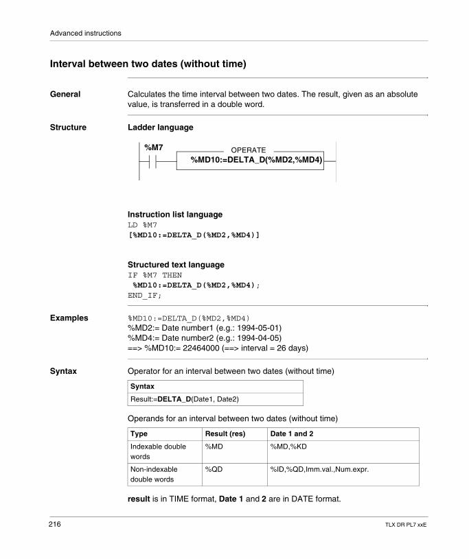
Advanced instructions
Interval between two dates (without time)
General Calculates the time interval between two dates. The result, given as an absolute value, is transferred in a double word.
Structure Ladder language
Instruction list languageLD %M7[%MD10:=DELTA_D(%MD2,%MD4)]
Structured text languageIF %M7 THEN %MD10:=DELTA_D(%MD2,%MD4);END_IF;
Examples %MD10:=DELTA_D(%MD2,%MD4)%MD2:= Date number1 (e.g.: 1994-05-01)%MD4:= Date number2 (e.g.: 1994-04-05)==> %MD10:= 22464000 (==> interval = 26 days)
Syntax Operator for an interval between two dates (without time)
Operands for an interval between two dates (without time)
result is in TIME format, Date 1 and 2 are in DATE format.
OPERATE%M7
%MD10:=DELTA_D(%MD2,%MD4)
Syntax
Result:=DELTA_D(Date1, Date2)
Type Result (res) Date 1 and 2
Indexable double words
%MD %MD,%KD
Non-indexable double words
%QD %ID,%QD,Imm.val.,Num.expr.
216 TLX DR PL7 xxE
Advanced instructions
The TIME format is defined with precision to a tenth of a second. The DATE format is defined with precision to a day. The calculated time interval will be a multiple of 864000 (= 1day = 24 h x 60 mn x 60 s x 10 tenths).
Note: � There is overflow if the result exceeds the maximum value permitted for a
duration (TIME). In this case, the result is equal to 0 and the system bit %S18 is set at 1.
� If one of the input parameters cannot be interpreted and is not coherent in DATE format, the system bit %S17 is set at 1 and the result is equal to 0.
TLX DR PL7 xxE 217
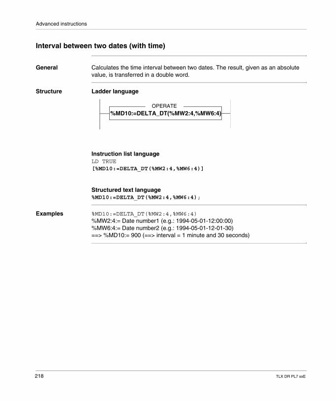
Advanced instructions
Interval between two dates (with time)
General Calculates the time interval between two dates. The result, given as an absolute value, is transferred in a double word.
Structure Ladder language
Instruction list languageLD TRUE[%MD10:=DELTA_DT(%MW2:4,%MW6:4)]
Structured text language%MD10:=DELTA_DT(%MW2:4,%MW6:4);
Examples %MD10:=DELTA_DT(%MW2:4,%MW6:4)%MW2:4:= Date number1 (e.g.: 1994-05-01-12:00:00)%MW6:4:= Date number2 (e.g.: 1994-05-01-12-01-30)==> %MD10:= 900 (==> interval = 1 minute and 30 seconds)
OPERATE
%MD10:=DELTA_DT(%MW2:4,%MW6:4)
218 TLX DR PL7 xxE
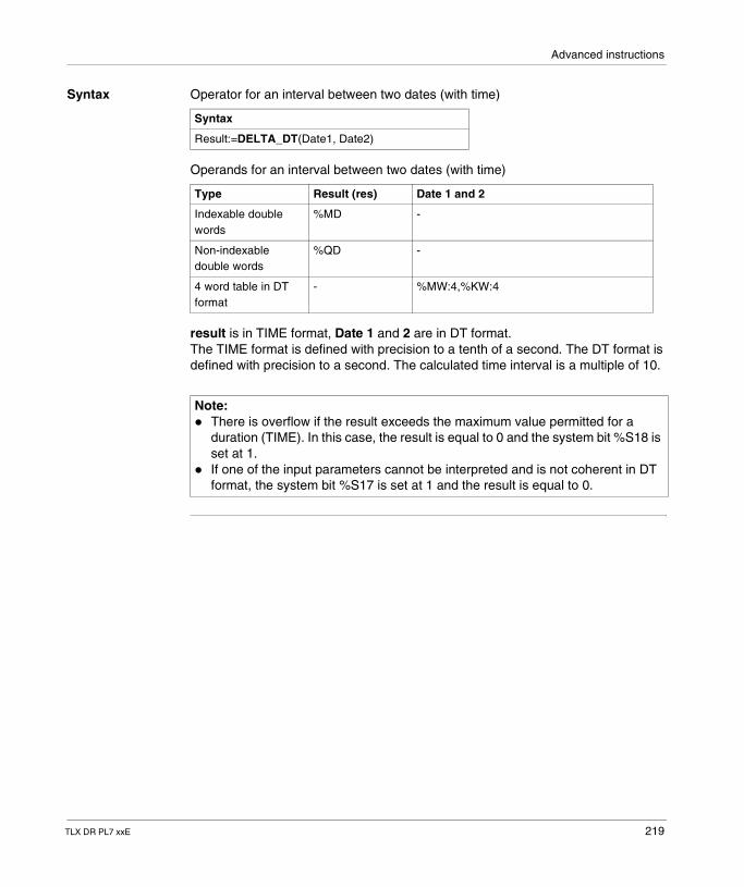
Advanced instructions
Syntax Operator for an interval between two dates (with time)
Operands for an interval between two dates (with time)
result is in TIME format, Date 1 and 2 are in DT format.The TIME format is defined with precision to a tenth of a second. The DT format is defined with precision to a second. The calculated time interval is a multiple of 10.
Syntax
Result:=DELTA_DT(Date1, Date2)
Type Result (res) Date 1 and 2
Indexable double words
%MD -
Non-indexable double words
%QD -
4 word table in DT format
- %MW:4,%KW:4
Note: � There is overflow if the result exceeds the maximum value permitted for a
duration (TIME). In this case, the result is equal to 0 and the system bit %S18 is set at 1.
� If one of the input parameters cannot be interpreted and is not coherent in DT format, the system bit %S17 is set at 1 and the result is equal to 0.
TLX DR PL7 xxE 219
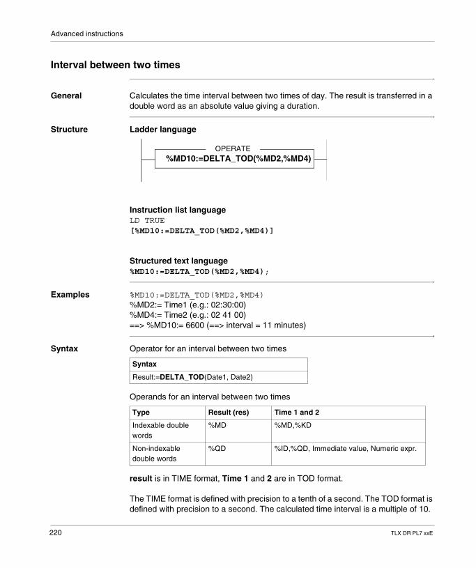
Advanced instructions
Interval between two times
General Calculates the time interval between two times of day. The result is transferred in a double word as an absolute value giving a duration.
Structure Ladder language
Instruction list languageLD TRUE[%MD10:=DELTA_TOD(%MD2,%MD4)]
Structured text language%MD10:=DELTA_TOD(%MD2,%MD4);
Examples %MD10:=DELTA_TOD(%MD2,%MD4)%MD2:= Time1 (e.g.: 02:30:00)%MD4:= Time2 (e.g.: 02 41 00)==> %MD10:= 6600 (==> interval = 11 minutes)
Syntax Operator for an interval between two times
Operands for an interval between two times
result is in TIME format, Time 1 and 2 are in TOD format.
The TIME format is defined with precision to a tenth of a second. The TOD format is defined with precision to a second. The calculated time interval is a multiple of 10.
OPERATE%MD10:=DELTA_TOD(%MD2,%MD4)
Syntax
Result:=DELTA_TOD(Date1, Date2)
Type Result (res) Time 1 and 2
Indexable double words
%MD %MD,%KD
Non-indexable double words
%QD %ID,%QD, Immediate value, Numeric expr.
220 TLX DR PL7 xxE
Advanced instructions
Note: If one of the input parameters cannot be interpreted and is not coherent in TOD format, the system bit %S17 is set at 1 and the result is equal to 0.
TLX DR PL7 xxE 221
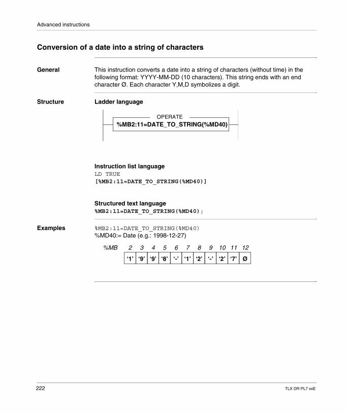
Advanced instructions
Conversion of a date into a string of characters
General This instruction converts a date into a string of characters (without time) in the following format: YYYY-MM-DD (10 characters). This string ends with an end character Ø. Each character Y,M,D symbolizes a digit.
Structure Ladder language
Instruction list languageLD TRUE[%MB2:11=DATE_TO_STRING(%MD40)]
Structured text language%MB2:11=DATE_TO_STRING(%MD40);
Examples %MB2:11=DATE_TO_STRING(%MD40)%MD40:= Date (e.g.: 1998-12-27)
OPERATE
%MB2:11=DATE_TO_STRING(%MD40)
2 3 4 5 6 7 8 9 10 11 12%MB
‘1’ ‘9’ ‘9’ ‘8’ ‘-’ ‘1’ ‘2’ ‘-’ ‘2’ ‘7’ Ø
222 TLX DR PL7 xxE
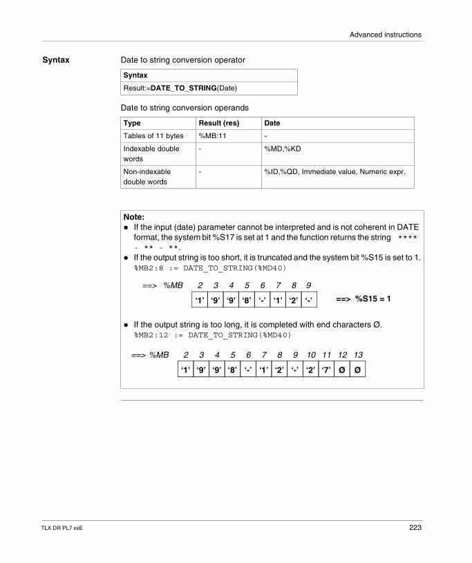
Advanced instructions
Syntax Date to string conversion operator
Date to string conversion operands
Syntax
Result:=DATE_TO_STRING(Date)
Type Result (res) Date
Tables of 11 bytes %MB:11 -
Indexable double words
- %MD,%KD
Non-indexable double words
- %ID,%QD, Immediate value, Numeric expr.
Note: � If the input (date) parameter cannot be interpreted and is not coherent in DATE
format, the system bit %S17 is set at 1 and the function returns the string **** - ** - **.
� If the output string is too short, it is truncated and the system bit %S15 is set to 1.%MB2:8 := DATE_TO_STRING(%MD40)
� If the output string is too long, it is completed with end characters Ø.%MB2:12 := DATE_TO_STRING(%MD40)
2 3 4 5 6 7 8%MB
‘1’ ‘9’ ‘9’ ‘8’ ‘-’ ‘1’ ‘2’
==>
==> %S15 = 1‘-’
9
2 3 4 5 6 7 8 9 10 11 12%MB
‘1’ ‘9’ ‘9’ ‘8’ ‘-’ ‘1’ ‘2’ ‘-’ ‘2’ ‘7’ Ø
13
Ø
==>
TLX DR PL7 xxE 223
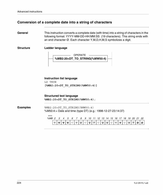
Advanced instructions
Conversion of a complete date into a string of characters
General This instruction converts a complete date (with time) into a string of characters in the following format: YYYY-MM-DD-HH:MM:SS (19 characters). This string ends with an end character Ø. Each character Y,M,D,H,M,S symbolizes a digit.
Structure Ladder language
Instruction list languageLD TRUE[%MB2:20=DT_TO_STRING(%MW50:4)]
Structured text language%MB2:20=DT_TO_STRING(%MW50:4);
Examples %MB2:20=DT_TO_STRING(%MW50:4)%M50:4:= Date and time (type DT) (e.g.: 1998-12-27-23:14:37)
OPERATE
%MB2:20=DT_TO_STRING(%MW50:4)
2 3 4 5 6 7 8 9 10 11 12
‘1’ ‘9’ ‘9’ ‘8’ ‘-’ ‘1’ ‘2’ ‘-’ ‘2’ ‘7’ ‘-’ ‘2’ ‘3’ ‘:’ ‘1’ ‘4’ ‘:’ ‘3’ ‘7’ Ø
13 14 15 16 17 18 19 20 21
Ø
22%MB==>
224 TLX DR PL7 xxE
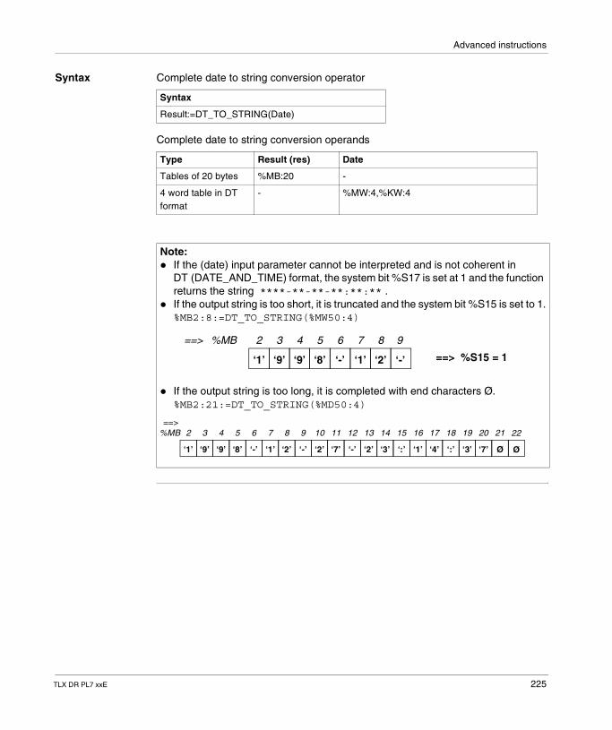
Advanced instructions
Syntax Complete date to string conversion operator
Complete date to string conversion operands
Syntax
Result:=DT_TO_STRING(Date)
Type Result (res) Date
Tables of 20 bytes %MB:20 -
4 word table in DT format
- %MW:4,%KW:4
Note: � If the (date) input parameter cannot be interpreted and is not coherent in
DT (DATE_AND_TIME) format, the system bit %S17 is set at 1 and the function returns the string ****-**-**-**:**:** .
� If the output string is too short, it is truncated and the system bit %S15 is set to 1.%MB2:8:=DT_TO_STRING(%MW50:4)
� If the output string is too long, it is completed with end characters Ø.%MB2:21:=DT_TO_STRING(%MD50:4)
2 3 4 5 6 7 8%MB
‘1’ ‘9’ ‘9’ ‘8’ ‘-’ ‘1’ ‘2’
==>
==> %S15 = 1‘-’
9
2 3 4 5 6 7 8 9 10 11 12
‘1’ ‘9’ ‘9’ ‘8’ ‘-’ ‘1’ ‘2’ ‘-’ ‘2’ ‘7’ ‘-’ ‘2’ ‘3’ ‘:’ ‘1’ ‘4’ ‘:’ ‘3’ ‘7’ Ø
13 14 15 16 17 18 19 20 21
Ø
22%MB==>
TLX DR PL7 xxE 225
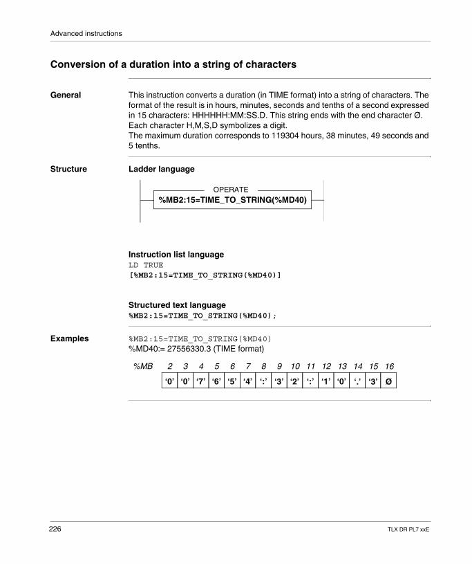
Advanced instructions
Conversion of a duration into a string of characters
General This instruction converts a duration (in TIME format) into a string of characters. The format of the result is in hours, minutes, seconds and tenths of a second expressed in 15 characters: HHHHHH:MM:SS.D. This string ends with the end character Ø. Each character H,M,S,D symbolizes a digit.The maximum duration corresponds to 119304 hours, 38 minutes, 49 seconds and 5 tenths.
Structure Ladder language
Instruction list languageLD TRUE[%MB2:15=TIME_TO_STRING(%MD40)]
Structured text language%MB2:15=TIME_TO_STRING(%MD40);
Examples %MB2:15=TIME_TO_STRING(%MD40)%MD40:= 27556330.3 (TIME format)
OPERATE
%MB2:15=TIME_TO_STRING(%MD40)
2 3 4 5 6 7 8 9 10 11 12%MB
‘0’ ‘0’ ‘7’ ‘6’ ‘5’ ‘4’ ‘:’ ‘3’ ‘2’ ‘:’ ‘1’
13
‘0’
14 15
‘.’ ‘3’
16
Ø
226 TLX DR PL7 xxE
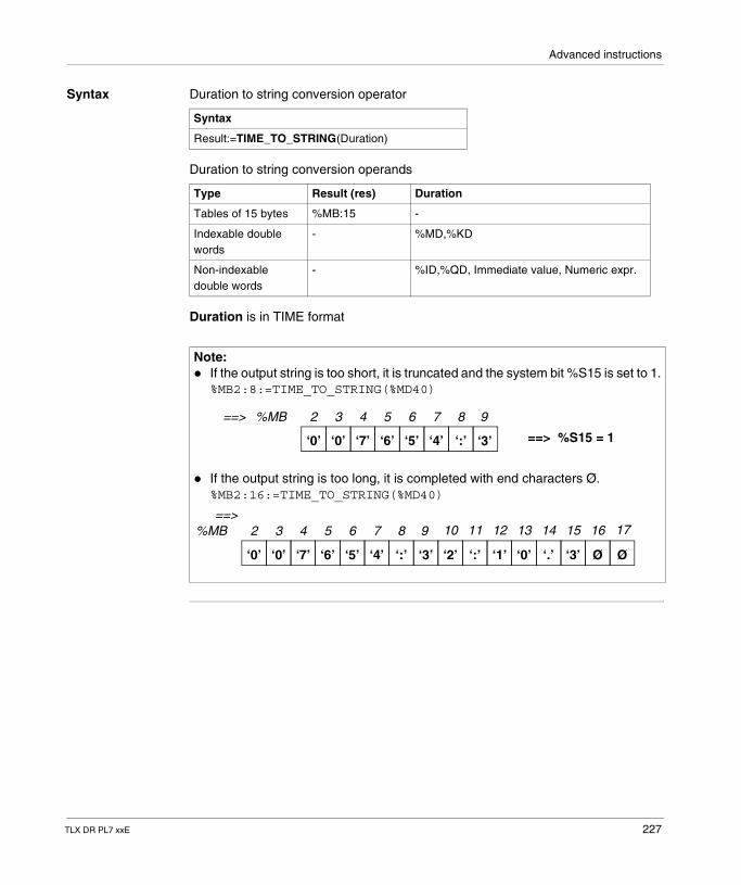
Advanced instructions
Syntax Duration to string conversion operator
Duration to string conversion operands
Duration is in TIME format
Syntax
Result:=TIME_TO_STRING(Duration)
Type Result (res) Duration
Tables of 15 bytes %MB:15 -
Indexable double words
- %MD,%KD
Non-indexable double words
- %ID,%QD, Immediate value, Numeric expr.
Note: � If the output string is too short, it is truncated and the system bit %S15 is set to 1.
%MB2:8:=TIME_TO_STRING(%MD40)
� If the output string is too long, it is completed with end characters Ø.%MB2:16:=TIME_TO_STRING(%MD40)
2 3 4 5 6 7 8%MB
‘0’ ‘0’ ‘7’ ‘6’ ‘5’ ‘4’ ‘:’
==>
==> %S15 = 1‘3’
9
2 3 4 5 6 7 8%MB
‘0’ ‘0’ ‘7’ ‘6’ ‘5’ ‘4’ ‘:’
==>
‘3’
9 10 11 12 13 14 15 16
‘2’ ‘:’ ‘1’ ‘0’ ‘.’ ‘3’ Ø
17
Ø
TLX DR PL7 xxE 227
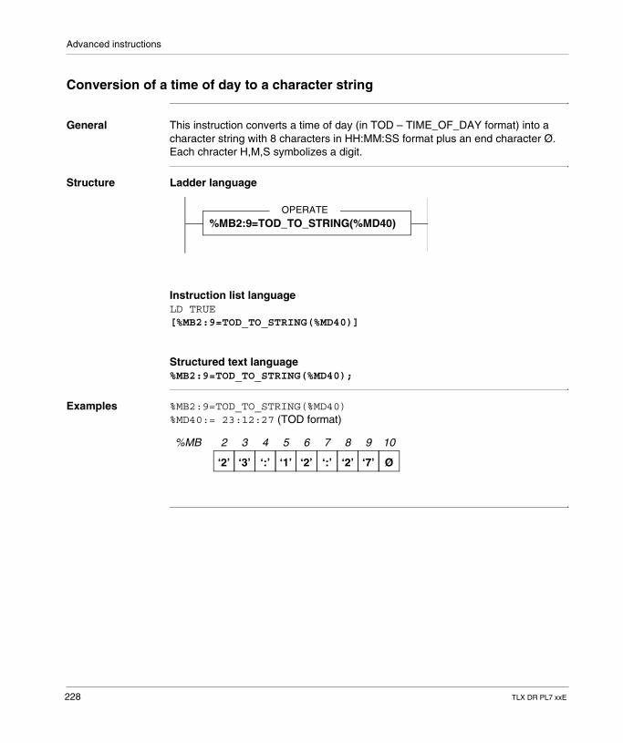
Advanced instructions
Conversion of a time of day to a character string
General This instruction converts a time of day (in TOD – TIME_OF_DAY format) into a character string with 8 characters in HH:MM:SS format plus an end character Ø. Each chracter H,M,S symbolizes a digit.
Structure Ladder language
Instruction list languageLD TRUE[%MB2:9=TOD_TO_STRING(%MD40)]
Structured text language%MB2:9=TOD_TO_STRING(%MD40);
Examples %MB2:9=TOD_TO_STRING(%MD40)%MD40:= 23:12:27 (TOD format)
OPERATE
%MB2:9=TOD_TO_STRING(%MD40)
2 3 4 5 6 7 8 9 10%MB
‘2’ ‘3’ ‘:’ ‘1’ ‘2’ ‘:’ ‘2’ ‘7’ Ø
228 TLX DR PL7 xxE
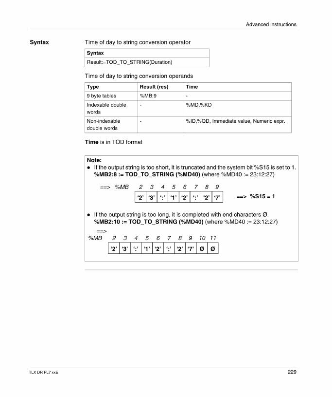
Advanced instructions
Syntax Time of day to string conversion operator
Time of day to string conversion operands
Time is in TOD format
Syntax
Result:=TOD_TO_STRING(Duration)
Type Result (res) Time
9 byte tables %MB:9 -
Indexable double words
- %MD,%KD
Non-indexable double words
- %ID,%QD, Immediate value, Numeric expr.
Note: � If the output string is too short, it is truncated and the system bit %S15 is set to 1.
%MB2:8 := TOD_TO_STRING (%MD40) (where %MD40 := 23:12:27)
� If the output string is too long, it is completed with end characters Ø.%MB2:10 := TOD_TO_STRING (%MD40) (where %MD40 := 23:12:27)
2 3 4 5 6 7 8%MB
‘2’ ‘3’ ‘:’ ‘1’ ‘2’ ‘:’ ‘2’
==>
==> %S15 = 1‘7’
9
2 3 4 5 6 7 8%MB
‘2’ ‘3’ ‘:’ ‘1’ ‘2’ ‘:’ ‘2’
==>
‘7’
9 10 11
Ø Ø
TLX DR PL7 xxE 229
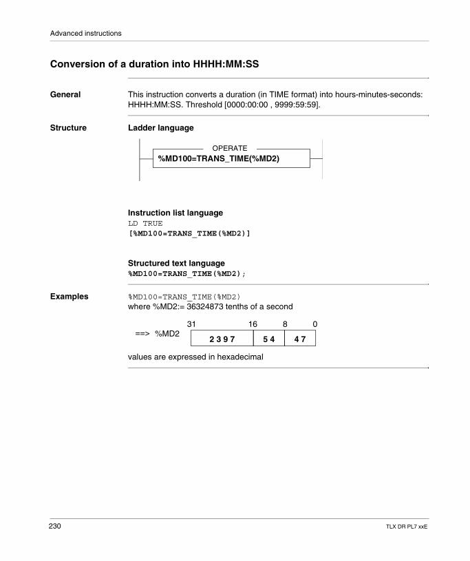
Advanced instructions
Conversion of a duration into HHHH:MM:SS
General This instruction converts a duration (in TIME format) into hours-minutes-seconds: HHHH:MM:SS. Threshold [0000:00:00 , 9999:59:59].
Structure Ladder language
Instruction list languageLD TRUE[%MD100=TRANS_TIME(%MD2)]
Structured text language%MD100=TRANS_TIME(%MD2);
Examples %MD100=TRANS_TIME(%MD2)where %MD2:= 36324873 tenths of a second
values are expressed in hexadecimal
OPERATE
%MD100=TRANS_TIME(%MD2)
31 16 8 0%MD2
2 3 9 7 5 4 4 7==>
230 TLX DR PL7 xxE
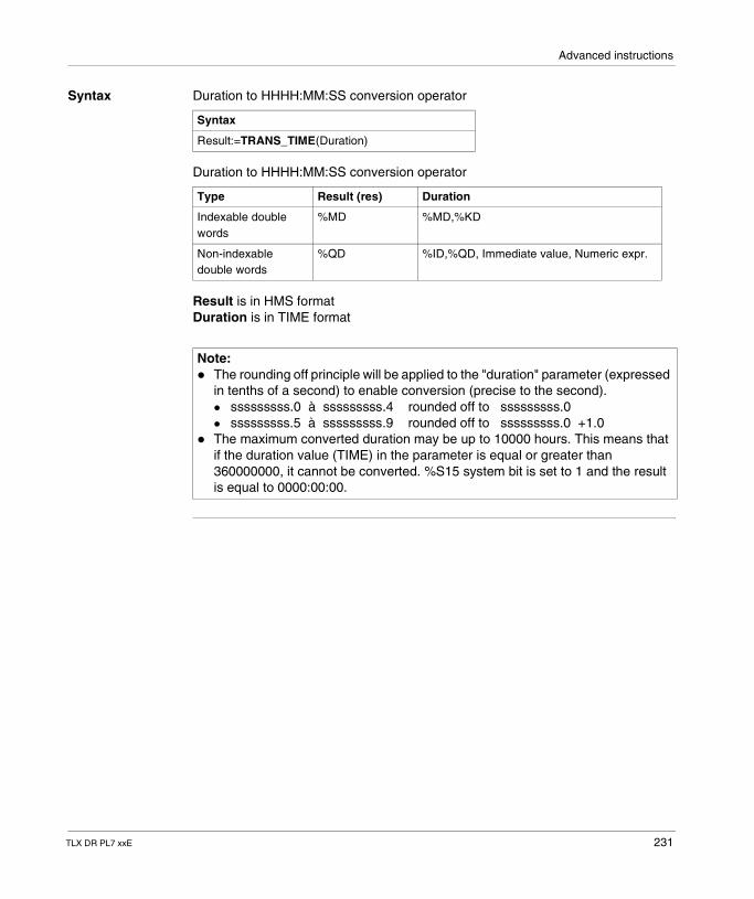
Advanced instructions
Syntax Duration to HHHH:MM:SS conversion operator
Duration to HHHH:MM:SS conversion operator
Result is in HMS formatDuration is in TIME format
Syntax
Result:=TRANS_TIME(Duration)
Type Result (res) Duration
Indexable double words
%MD %MD,%KD
Non-indexable double words
%QD %ID,%QD, Immediate value, Numeric expr.
Note: � The rounding off principle will be applied to the "duration" parameter (expressed
in tenths of a second) to enable conversion (precise to the second).� sssssssss.0 à sssssssss.4 rounded off to sssssssss.0� sssssssss.5 à sssssssss.9 rounded off to sssssssss.0 +1.0
� The maximum converted duration may be up to 10000 hours. This means that if the duration value (TIME) in the parameter is equal or greater than 360000000, it cannot be converted. %S15 system bit is set to 1 and the result is equal to 0000:00:00.
TLX DR PL7 xxE 231
Advanced instructions
2.9 Bit table instructions
Introduction
Aim of this sub-section
This sub-section describes PL7 language bit table instructions
What's in this Section?
This Section contains the following Maps:
Topic Page
Copying a bit table into a bit table 233
Logic instructions on bit tables 234
Copying a bit table into a word table 236
Copy of a word table in a bits table 238
232 TLX DR PL7 xxE
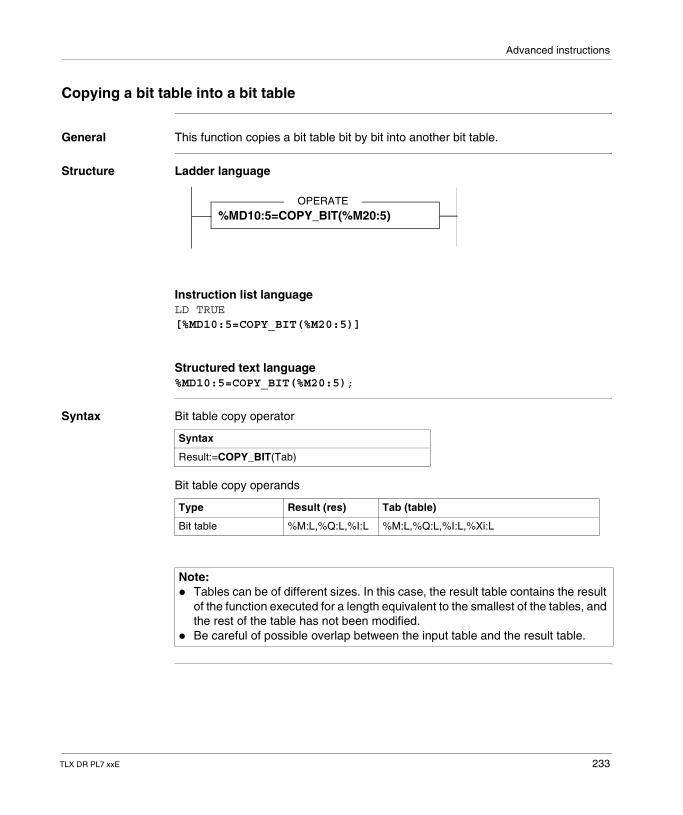
Advanced instructions
Copying a bit table into a bit table
General This function copies a bit table bit by bit into another bit table.
Structure Ladder language
Instruction list languageLD TRUE[%MD10:5=COPY_BIT(%M20:5)]
Structured text language%MD10:5=COPY_BIT(%M20:5);
Syntax Bit table copy operator
Bit table copy operands
OPERATE%MD10:5=COPY_BIT(%M20:5)
Syntax
Result:=COPY_BIT(Tab)
Type Result (res) Tab (table)
Bit table %M:L,%Q:L,%I:L %M:L,%Q:L,%I:L,%Xi:L
Note: � Tables can be of different sizes. In this case, the result table contains the result
of the function executed for a length equivalent to the smallest of the tables, and the rest of the table has not been modified.
� Be careful of possible overlap between the input table and the result table.
TLX DR PL7 xxE 233
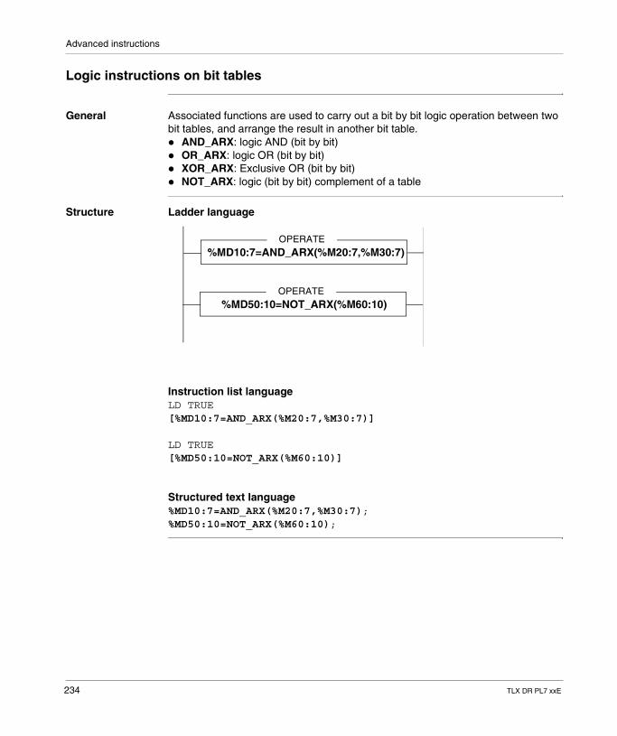
Advanced instructions
Logic instructions on bit tables
General Associated functions are used to carry out a bit by bit logic operation between two bit tables, and arrange the result in another bit table.� AND_ARX: logic AND (bit by bit)� OR_ARX: logic OR (bit by bit)� XOR_ARX: Exclusive OR (bit by bit)� NOT_ARX: logic (bit by bit) complement of a table
Structure Ladder language
Instruction list languageLD TRUE[%MD10:7=AND_ARX(%M20:7,%M30:7)]
LD TRUE[%MD50:10=NOT_ARX(%M60:10)]
Structured text language%MD10:7=AND_ARX(%M20:7,%M30:7);%MD50:10=NOT_ARX(%M60:10);
OPERATE%MD10:7=AND_ARX(%M20:7,%M30:7)
OPERATE%MD50:10=NOT_ARX(%M60:10)
234 TLX DR PL7 xxE
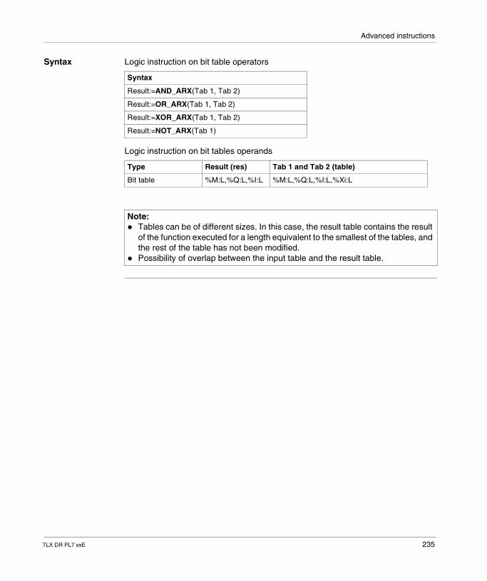
Advanced instructions
Syntax Logic instruction on bit table operators
Logic instruction on bit tables operands
Syntax
Result:=AND_ARX(Tab 1, Tab 2)
Result:=OR_ARX(Tab 1, Tab 2)
Result:=XOR_ARX(Tab 1, Tab 2)
Result:=NOT_ARX(Tab 1)
Type Result (res) Tab 1 and Tab 2 (table)
Bit table %M:L,%Q:L,%I:L %M:L,%Q:L,%I:L,%Xi:L
Note: � Tables can be of different sizes. In this case, the result table contains the result
of the function executed for a length equivalent to the smallest of the tables, and the rest of the table has not been modified.
� Possibility of overlap between the input table and the result table.
TLX DR PL7 xxE 235
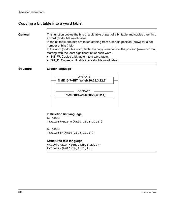
Advanced instructions
Copying a bit table into a word table
General This function copies the bits of a bit table or part of a bit table and copies them into a word (or double word) table.In the bit table, the bits are taken starting from a certain position (brow) for a set number of bits (nbit).In the word (or double word) table, the copy is made from the position (wrow or drow) starting with the least significant bit of each word.� BIT_W: Copies a bit table into a word table.� BIT_D: Copies a bit table into a double word table.
Structure Ladder language
Instruction list languageLD TRUE[%MD10:7=BIT_W(%M20:29,3,22,2)]
LD TRUE[%MD10:4=(%M20:29,3,22,1)]
Structured text language%MD10:7=BIT_W(%M20:29,3,22,2);%MD10:4=(%M20:29,3,22,1);
OPERATE
%MD10:7=BIT_W(%M20:29,3,22,2)
OPERATE
%MD10:4=(%M20:29,3,22,1)
236 TLX DR PL7 xxE
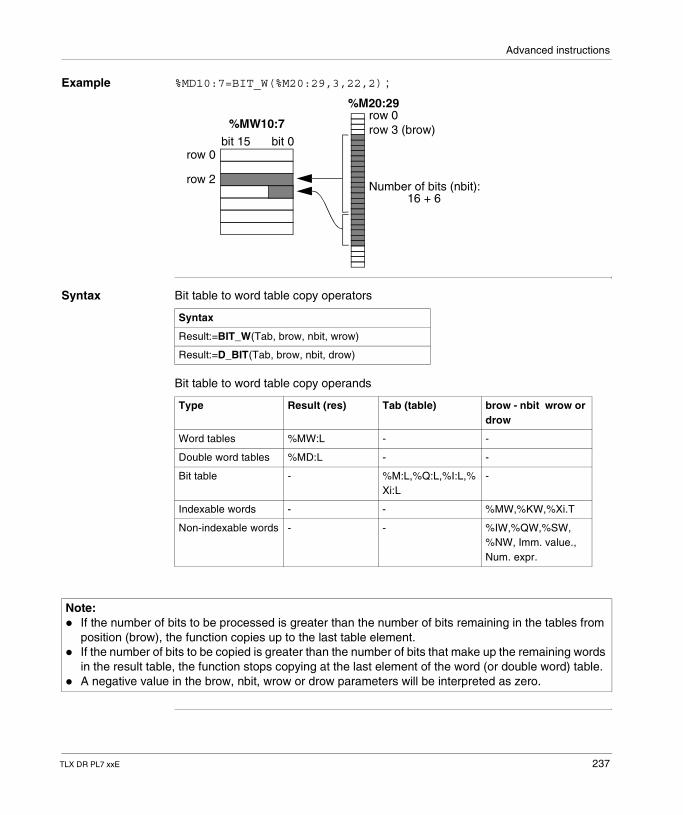
Advanced instructions
Example %MD10:7=BIT_W(%M20:29,3,22,2) ;
Syntax Bit table to word table copy operators
Bit table to word table copy operands
%M20:29row 0row 3 (brow)
Number of bits (nbit):16 + 6
row 0bit 15 bit 0
row 2
%MW10:7
Syntax
Result:=BIT_W(Tab, brow, nbit, wrow)
Result:=D_BIT(Tab, brow, nbit, drow)
Type Result (res) Tab (table) brow - nbit wrow or drow
Word tables %MW:L - -
Double word tables %MD:L - -
Bit table - %M:L,%Q:L,%I:L,%Xi:L
-
Indexable words - - %MW,%KW,%Xi.T
Non-indexable words - - %IW,%QW,%SW, %NW, Imm. value., Num. expr.
Note: � If the number of bits to be processed is greater than the number of bits remaining in the tables from
position (brow), the function copies up to the last table element.� If the number of bits to be copied is greater than the number of bits that make up the remaining words
in the result table, the function stops copying at the last element of the word (or double word) table.� A negative value in the brow, nbit, wrow or drow parameters will be interpreted as zero.
TLX DR PL7 xxE 237
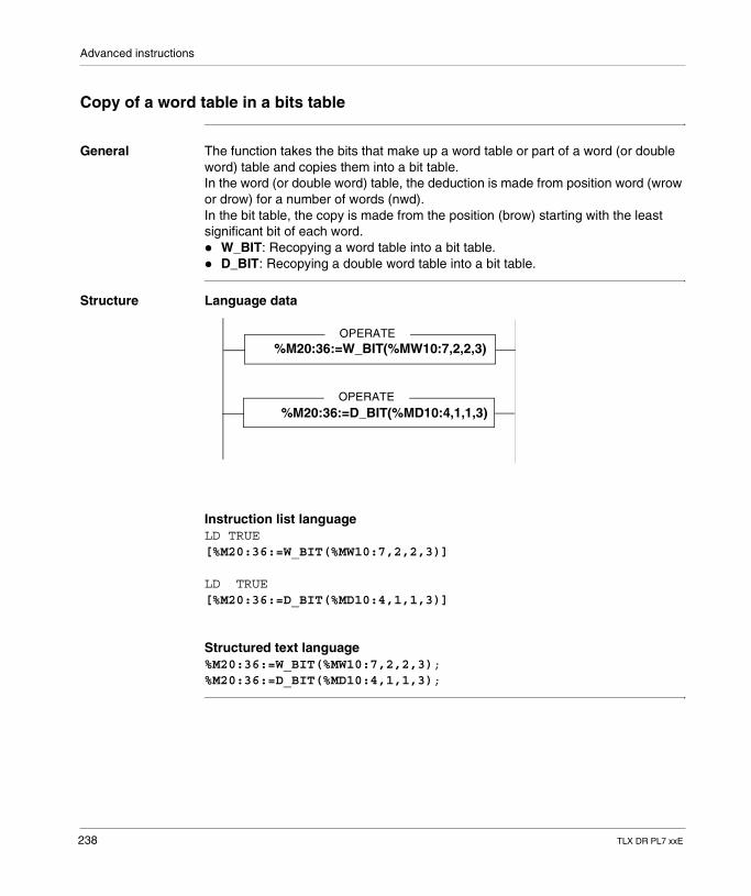
Advanced instructions
Copy of a word table in a bits table
General The function takes the bits that make up a word table or part of a word (or double word) table and copies them into a bit table.In the word (or double word) table, the deduction is made from position word (wrow or drow) for a number of words (nwd).In the bit table, the copy is made from the position (brow) starting with the least significant bit of each word.� W_BIT: Recopying a word table into a bit table.� D_BIT: Recopying a double word table into a bit table.
Structure Language data
Instruction list languageLD TRUE[%M20:36:=W_BIT(%MW10:7,2,2,3)]
LD TRUE[%M20:36:=D_BIT(%MD10:4,1,1,3)]
Structured text language%M20:36:=W_BIT(%MW10:7,2,2,3);%M20:36:=D_BIT(%MD10:4,1,1,3);
OPERATE%M20:36:=W_BIT(%MW10:7,2,2,3)
OPERATE%M20:36:=D_BIT(%MD10:4,1,1,3)
238 TLX DR PL7 xxE
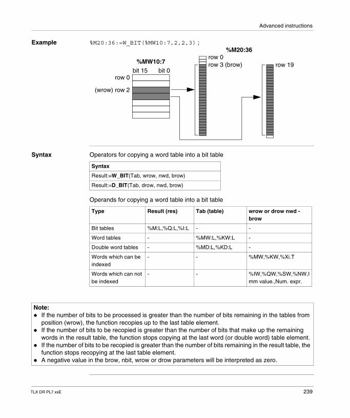
Advanced instructions
Example %M20:36:=W_BIT(%MW10:7,2,2,3) ;
Syntax Operators for copying a word table into a bit table
Operands for copying a word table into a bit table
%M20:36row 0row 3 (brow)
row 0bit 15 bit 0
(wrow) row 2
%MW10:7 row 19
Syntax
Result:=W_BIT(Tab, wrow, nwd, brow)
Result:=D_BIT(Tab, drow, nwd, brow)
Type Result (res) Tab (table) wrow or drow nwd -brow
Bit tables %M:L,%Q:L,%I:L - -
Word tables - %MW:L,%KW:L -
Double word tables - %MD:L,%KD:L -
Words which can be indexed
- - %MW,%KW,%Xi.T
Words which can not be indexed
- - %IW,%QW,%SW,%NW,Imm value.,Num. expr.
Note: � If the number of bits to be processed is greater than the number of bits remaining in the tables from
position (wrow), the function recopies up to the last table element.� If the number of bits to be recopied is greater than the number of bits that make up the remaining
words in the result table, the function stops copying at the last word (or double word) table element.� If the number of bits to be recopied is greater than the number of bits remaining in the result table, the
function stops recopying at the last table element.� A negative value in the brow, nbit, wrow or drow parameters will be interpreted as zero.
TLX DR PL7 xxE 239
Advanced instructions
2.10 "Orpheus" functions: Shift registers, counter
Introduction
Aim of this sub-section
This sub-section describes the following "Orpheus" functions of PL7 language: shift register and counter
What's in this Section?
This Section contains the following Maps:
Topic Page
Shift register on words with shifted bit retrieval 241
Up/down counting with overshoot signaling 244
Rotate shifts 247
240 TLX DR PL7 xxE
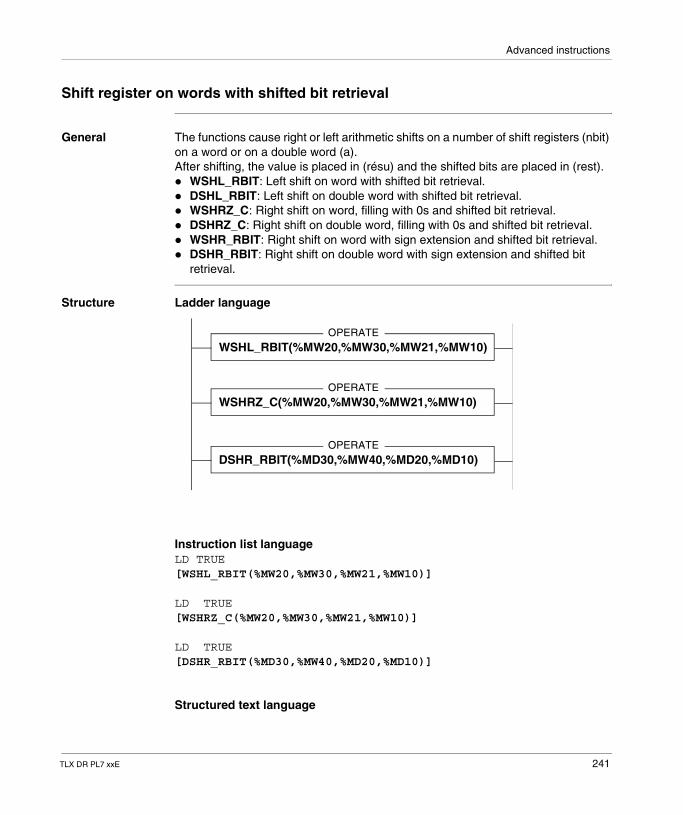
Advanced instructions
Shift register on words with shifted bit retrieval
General The functions cause right or left arithmetic shifts on a number of shift registers (nbit) on a word or on a double word (a).After shifting, the value is placed in (résu) and the shifted bits are placed in (rest).� WSHL_RBIT: Left shift on word with shifted bit retrieval.� DSHL_RBIT: Left shift on double word with shifted bit retrieval.� WSHRZ_C: Right shift on word, filling with 0s and shifted bit retrieval.� DSHRZ_C: Right shift on double word, filling with 0s and shifted bit retrieval.� WSHR_RBIT: Right shift on word with sign extension and shifted bit retrieval.� DSHR_RBIT: Right shift on double word with sign extension and shifted bit
retrieval.
Structure Ladder language
Instruction list languageLD TRUE[WSHL_RBIT(%MW20,%MW30,%MW21,%MW10)]
LD TRUE[WSHRZ_C(%MW20,%MW30,%MW21,%MW10)]
LD TRUE[DSHR_RBIT(%MD30,%MW40,%MD20,%MD10)]
Structured text language
OPERATEWSHL_RBIT(%MW20,%MW30,%MW21,%MW10)
OPERATEWSHRZ_C(%MW20,%MW30,%MW21,%MW10)
OPERATEDSHR_RBIT(%MD30,%MW40,%MD20,%MD10)
TLX DR PL7 xxE 241
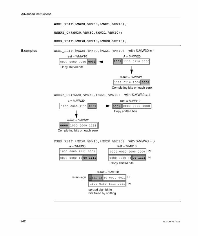
Advanced instructions
WSHL_RBIT(%MW20,%MW30,%MW21,%MW10);
WSHRZ_C(%MW20,%MW30,%MW21,%MW10);
DSHR_RBIT(%MD30,%MW40,%MD20,%MD10);
Examples WSHL_RBIT(%MW20,%MW30,%MW21,%MW10) with %MW30 = 4
WSHRZ_C(%MW20,%MW30,%MW21,%MW10) with %MW30 = 4
DSHR_RBIT(%MD30,%MW40,%MD20,%MD10) with %MW40 = 6
0000 0000 0000 0001
rest = %MW10
1111 0110 10000001
1111 0110 1000 0000
A = %MW20
result = %MW21
Copy shifted bits
Completing bits on each zero
1000 0000 1111 0000 0000 00000001
a = %MW20 rest = %MW10
result = %MW21
Completing bits on each zero
Copy shifted bits
0001
1000 0000 11110000
1000 0000 1111 0001
0000 0000 11 00 1111 0000 0000 11 00 1111
PF
Pf
1100 0100 1111 0011
1111 11 10 0000 0011 PF
Pf
0000 0000 0000 0000
rest = %MD10a = %MD30
result = %MD20
retain sign
Copy shifted bits
spread sign bit inbits freed by shifting
242 TLX DR PL7 xxE
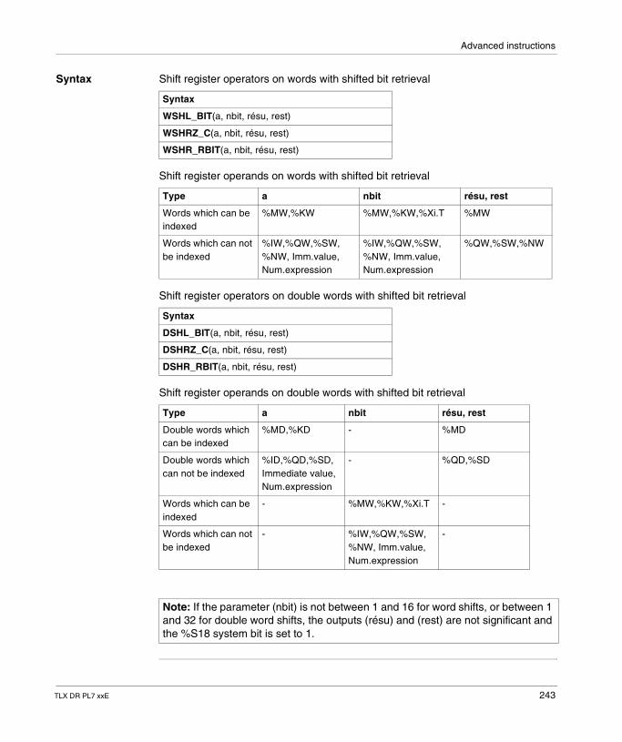
Advanced instructions
Syntax Shift register operators on words with shifted bit retrieval
Shift register operands on words with shifted bit retrieval
Shift register operators on double words with shifted bit retrieval
Shift register operands on double words with shifted bit retrieval
Syntax
WSHL_BIT(a, nbit, résu, rest)
WSHRZ_C(a, nbit, résu, rest)
WSHR_RBIT(a, nbit, résu, rest)
Type a nbit résu, rest
Words which can be indexed
%MW,%KW %MW,%KW,%Xi.T %MW
Words which can not be indexed
%IW,%QW,%SW, %NW, Imm.value, Num.expression
%IW,%QW,%SW, %NW, Imm.value, Num.expression
%QW,%SW,%NW
Syntax
DSHL_BIT(a, nbit, résu, rest)
DSHRZ_C(a, nbit, résu, rest)
DSHR_RBIT(a, nbit, résu, rest)
Type a nbit résu, rest
Double words which can be indexed
%MD,%KD - %MD
Double words which can not be indexed
%ID,%QD,%SD, Immediate value, Num.expression
- %QD,%SD
Words which can be indexed
- %MW,%KW,%Xi.T -
Words which can not be indexed
- %IW,%QW,%SW,%NW, Imm.value, Num.expression
-
Note: If the parameter (nbit) is not between 1 and 16 for word shifts, or between 1 and 32 for double word shifts, the outputs (résu) and (rest) are not significant and the %S18 system bit is set to 1.
TLX DR PL7 xxE 243
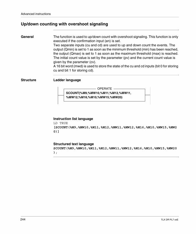
Advanced instructions
Up/down counting with overshoot signaling
General The function is used to up/down count with overshoot signaling. This function is only executed if the confirmation input (en) is set.Two separate inputs (cu and cd) are used to up and down count the events. The output (Qmin) is set to 1 as soon as the minimum threshold (min) has been reached, the output (Qmax) is set to 1 as soon as the maximum threshold (max) is reached.The initial count value is set by the parameter (pv) and the current count value is given by the parameter (cv).A 16 bit word (mwd) is used to store the state of the cu and cd inputs (bit 0 for storing cu and bit 1 for storing cd).
Structure Ladder language
Instruction list languageLD TRUE[SCOUNT(%M9,%MW10,%M11,%M12,%MW11,%MW12,%M16,%M10,%MW15,%MW20)]
Structured text languageSCOUNT(%M9,%MW10,%M11,%M12,%MW11,%MW12,%M16,%M10,%MW15,%MW20);
OPERATESCOUNT(%M9,%MW10,%M11,%M12,%MW11,%MW12,%M16,%M10,%MW15,%MW20)
244 TLX DR PL7 xxE
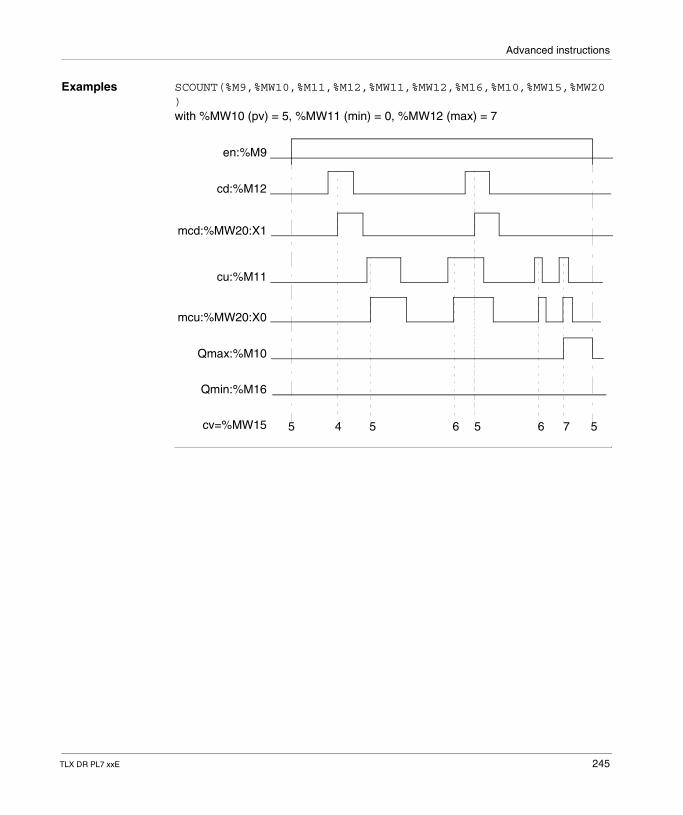
Advanced instructions
Examples SCOUNT(%M9,%MW10,%M11,%M12,%MW11,%MW12,%M16,%M10,%MW15,%MW20)with %MW10 (pv) = 5, %MW11 (min) = 0, %MW12 (max) = 7
5 4 5 6 5 6 7 5
en:%M9
cd:%M12
mcd:%MW20:X1
cu:%M11
Qmax:%M10
Qmin:%M16
cv=%MW15
mcu:%MW20:X0
TLX DR PL7 xxE 245
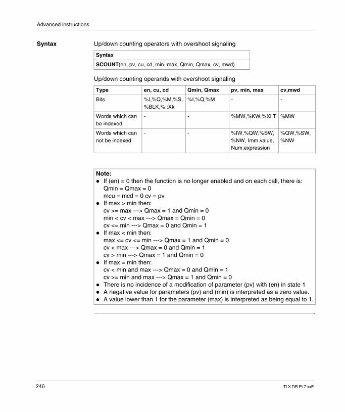
Advanced instructions
Syntax Up/down counting operators with overshoot signaling
Up/down counting operands with overshoot signaling
Syntax
SCOUNT(en, pv, cu, cd, min, max, Qmin, Qmax, cv, mwd)
Type en, cu, cd Qmin, Qmax pv, min, max cv,mwd
Bits %I,%Q,%M,%S,%BLK,%.:Xk
%I,%Q,%M - -
Words which can be indexed
- - %MW,%KW,%Xi.T %MW
Words which can not be indexed
- - %IW,%QW,%SW,%NW, Imm.value, Num.expression
%QW,%SW,%NW
Note: � If (en) = 0 then the function is no longer enabled and on each call, there is:
Qmin = Qmax = 0 mcu = mcd = 0 cv = pv
� If max > min then: cv >= max ---> Qmax = 1 and Qmin = 0 min < cv < max ---> Qmax = Qmin = 0 cv <= min ---> Qmax = 0 and Qmin = 1
� If max < min then: max <= cv <= min ---> Qmax = 1 and Qmin = 0 cv < max ---> Qmax = 0 and Qmin = 1 cv > min ---> Qmax = 1 and Qmin = 0
� If max = min then:cv < min and max ---> Qmax = 0 and Qmin = 1cv >= min and max ---> Qmax = 1 and Qmin = 0
� There is no incidence of a modification of parameter (pv) with (en) in state 1� A negative value for parameters (pv) and (min) is interpreted as a zero value.� A value lower than 1 for the parameter (max) is interpreted as being equal to 1.
246 TLX DR PL7 xxE
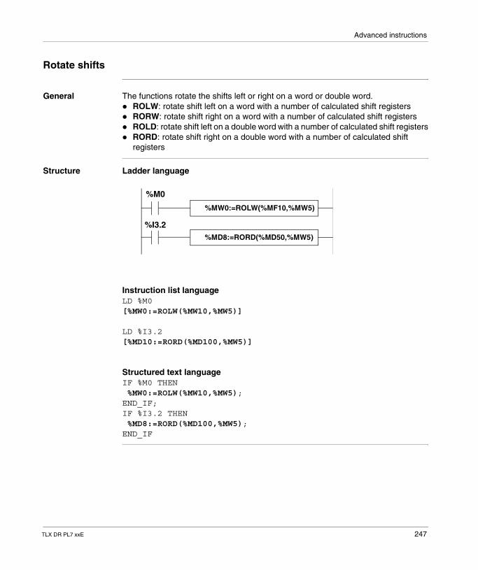
Advanced instructions
Rotate shifts
General The functions rotate the shifts left or right on a word or double word.� ROLW: rotate shift left on a word with a number of calculated shift registers� RORW: rotate shift right on a word with a number of calculated shift registers� ROLD: rotate shift left on a double word with a number of calculated shift registers� RORD: rotate shift right on a double word with a number of calculated shift
registers
Structure Ladder language
Instruction list languageLD %M0[%MW0:=ROLW(%MW10,%MW5)]
LD %I3.2[%MD10:=RORD(%MD100,%MW5)]
Structured text languageIF %M0 THEN %MW0:=ROLW(%MW10,%MW5);END_IF;IF %I3.2 THEN %MD8:=RORD(%MD100,%MW5);END_IF
%MW0:=ROLW(%MF10,%MW5)
%MD8:=RORD(%MD50,%MW5)
%M0
%I3.2
TLX DR PL7 xxE 247
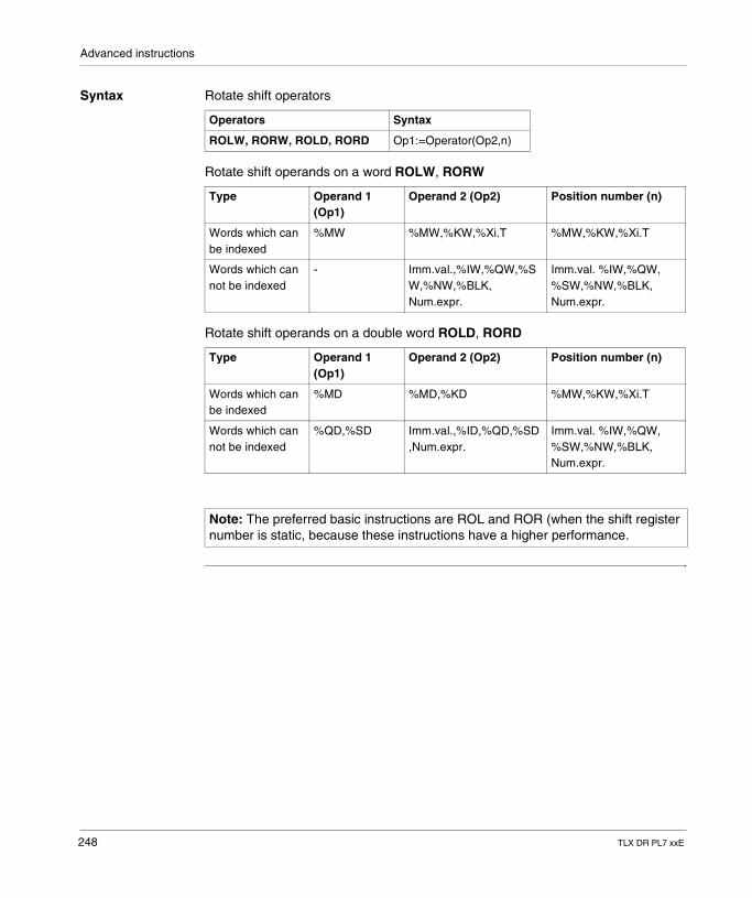
Advanced instructions
Syntax Rotate shift operators
Rotate shift operands on a word ROLW, RORW
Rotate shift operands on a double word ROLD, RORD
Operators Syntax
ROLW, RORW, ROLD, RORD Op1:=Operator(Op2,n)
Type Operand 1 (Op1)
Operand 2 (Op2) Position number (n)
Words which can be indexed
%MW %MW,%KW,%Xi.T %MW,%KW,%Xi.T
Words which can not be indexed
- Imm.val.,%IW,%QW,%SW,%NW,%BLK, Num.expr.
Imm.val. %IW,%QW, %SW,%NW,%BLK, Num.expr.
Type Operand 1 (Op1)
Operand 2 (Op2) Position number (n)
Words which can be indexed
%MD %MD,%KD %MW,%KW,%Xi.T
Words which can not be indexed
%QD,%SD Imm.val.,%ID,%QD,%SD,Num.expr.
Imm.val. %IW,%QW, %SW,%NW,%BLK, Num.expr.
Note: The preferred basic instructions are ROL and ROR (when the shift register number is static, because these instructions have a higher performance.
248 TLX DR PL7 xxE
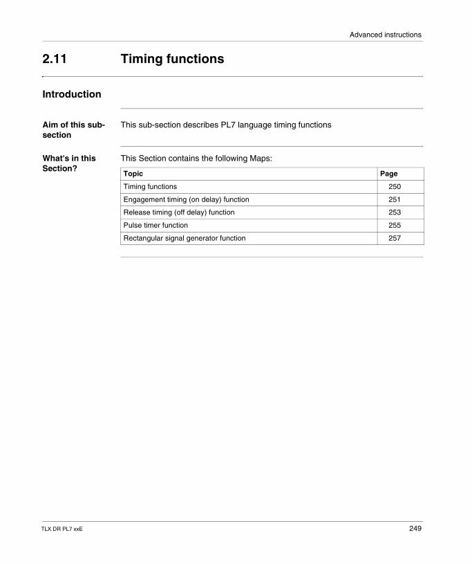
Advanced instructions
2.11 Timing functions
Introduction
Aim of this sub-section
This sub-section describes PL7 language timing functions
What's in this Section?
This Section contains the following Maps:
Topic Page
Timing functions 250
Engagement timing (on delay) function 251
Release timing (off delay) function 253
Pulse timer function 255
Rectangular signal generator function 257
TLX DR PL7 xxE 249
Advanced instructions
Timing functions
General As opposed to the predefined function blocks, these timing functions are not limited in number and can be used in the DFB function block code. 4 timing functions are available.� FTON: Engagement timing (on delay).� FTOF: Release timing (off delay).� FTP: Pulse timing: Timing� FPULSOR: rectangular signal: Timing
250 TLX DR PL7 xxE
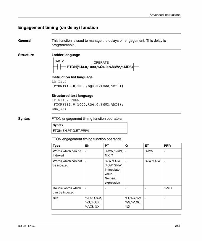
Advanced instructions
Engagement timing (on delay) function
General This function is used to manage the delays on engagement. This delay is programmable
Structure Ladder language
Instruction list languageLD I1.2[FTON(%I3.0,1000,%Q4.0,%MW2,%MD8)]
Structured text languageIF %I1.2 THEN FTON(%I3.0,1000,%Q4.0,%MW2,%MD8);END_IF;
Syntax FTON engagement timing function operators
FTON engagement timing function operands
OPERATE
FTON(%I3.0,1000,%Q4.0,%MW2,%MD8)
%I1.2
Syntax
FTON(EN,PT,Q,ET,PRIV)
Type EN PT Q ET PRIV
Words which can be indexed
- %MW,%KW,%Xi.T
- %MW -
Words which can not be indexed
- %IW,%QW,%SW,%NW, Immediate value, Numeric expression
- %IW,%QW -
Double words which can be indexed
- - - - %MD
Bits %I,%Q,%M,%S,%BLK,%*:Xk,%X
%I,%Q,%M%S,%*:Xk,%X
- -
TLX DR PL7 xxE 251
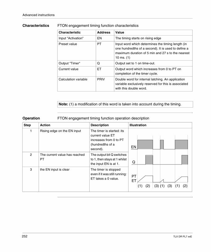
Advanced instructions
Characteristics FTON engagement timing function characteristics
Operation FTON engagement timing function operation description
Characteristic Address Value
Input "Activation" EN The timing starts on rising edge
Preset value PT Input word which determines the timing length (in one hundredths of a second). It is used to define a maximum duration of 5 min and 27 s to the nearest 10 ms. (1)
Output "Timer" Q Output set to 1 on time-out.
Current value ET Output word which increases from 0 to PT on completion of the timer cycle.
Calculation variable PRIV Double word for internal latching. An application variable exclusively reserved for this is associated with this double word.
Note: (1) a modification of this word is taken into account during the timing.
Step Action Description Illustration
1 Rising edge on the EN input The timer is started: its current value ET increases from 0 to PT (hundredths of a second).
2 The current value has reached PT
The output bit Q switches to 1, then stays at 1 whilst the input EN is at 1.
3 the EN input is clear The timer is stopped even if it was still running: ET takes a 0 value.
ETPT
Q
EN
(1) (2) (3) (1) (3) (1) (2)
252 TLX DR PL7 xxE
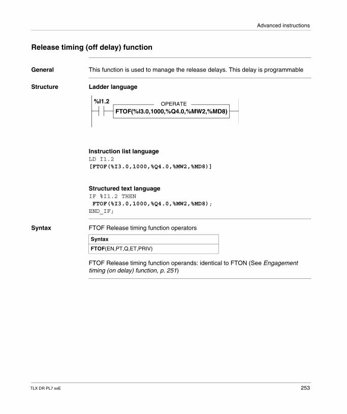
Advanced instructions
Release timing (off delay) function
General This function is used to manage the release delays. This delay is programmable
Structure Ladder language
Instruction list languageLD I1.2[FTOF(%I3.0,1000,%Q4.0,%MW2,%MD8)]
Structured text languageIF %I1.2 THEN FTOF(%I3.0,1000,%Q4.0,%MW2,%MD8);END_IF;
Syntax FTOF Release timing function operators
FTOF Release timing function operands: identical to FTON (See Engagement timing (on delay) function, p. 251)
OPERATEFTOF(%I3.0,1000,%Q4.0,%MW2,%MD8)
%I1.2
Syntax
FTOF(EN,PT,Q,ET,PRIV)
TLX DR PL7 xxE 253
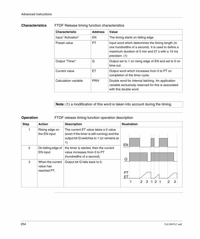
Advanced instructions
Characteristics FTOF Release timing function characteristics
Operation FTOF release timing function operation description
Characteristic Address Value
Input "Activation" EN The timing starts on falling edge
Preset value PT Input word which determines the timing length (in one hundredths of a second). It is used to define a maximum duration of 5 min and 27 s with a 10 ms precision. (1)
Output "Timer" Q Output set to 1 on rising edge of EN and set to 0 on time-out.
Current value ET Output word which increases from 0 to PT on completion of the timer cycle.
Calculation variable PRIV Double word for internal latching. An application variable exclusively reserved for this is associated with this double word.
Note: (1) a modification of this word is taken into account during the timing.
Step Action Description Illustration
1 Rising edge on the EN input
The current ET value takes a 0 value (even if the timer is still running) and the output bit Q switches to 1 (or remains at 1)
2 On falling edge of EN input
the timer is started, then the current value increases from 0 to PT (hundredths of a second).
3 When the current value has reached PT.
Output bit Q falls back to 0.
ETPT
Q
EN
1 2 1 1 223 3
254 TLX DR PL7 xxE
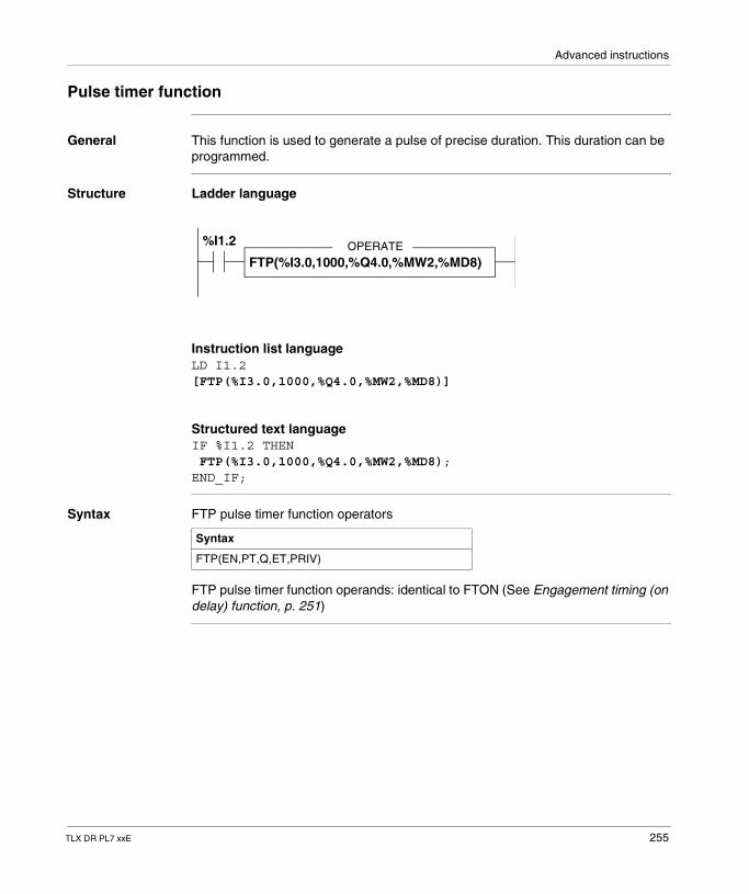
Advanced instructions
Pulse timer function
General This function is used to generate a pulse of precise duration. This duration can be programmed.
Structure Ladder language
Instruction list languageLD I1.2[FTP(%I3.0,1000,%Q4.0,%MW2,%MD8)]
Structured text languageIF %I1.2 THEN FTP(%I3.0,1000,%Q4.0,%MW2,%MD8);END_IF;
Syntax FTP pulse timer function operators
FTP pulse timer function operands: identical to FTON (See Engagement timing (on delay) function, p. 251)
OPERATEFTP(%I3.0,1000,%Q4.0,%MW2,%MD8)
%I1.2
Syntax
FTP(EN,PT,Q,ET,PRIV)
TLX DR PL7 xxE 255

Advanced instructions
Characteristics FTP pulse timer function characteristics
Operation FTP pulse timer function operating description
Characteristic Address Value
Input "Activation" EN The timing starts on falling edge
Preset value PT Input word which determines the timing length (in one hundredths of a second). It is used to define a maximum duration of 5 min and 27 s with a 10 ms precision. (1)
Output "Timer" Q Output set to 1 on time-out.
Current value ET Output word which increases from 0 to PT on completion of the timer cycle.
Calculation variable PRIV Double word for internal latching. An application variable exclusively reserved for this is associated with this double word.
Note: (1) a modification of this word is taken into account during the timing.
Step Action Description Illustration
1 Rising edge on the EN input
The timer is started (if it is not already on) and the current ET value advances from 0 to PT (hundredths of a second). Output bit Q switches to 1
This monostable cannot be reactivated.
2 When the current value has reached PT.
Output bit Q falls back to 0.
3 The EN input and output Q are at 0
PT takes a 0 value.
ETPT
Q
EN
1 2 1 13 3 2
256 TLX DR PL7 xxE
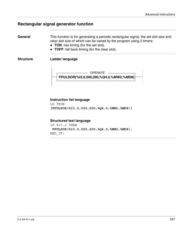
Advanced instructions
Rectangular signal generator function
General This function is for generating a periodic rectangular signal, the set slot size and clear slot size of which can be varied by the program using 2 timers:� TON: rise timing (for the set slot).� TOFF: fall back timing (for the clear slot).
Structure Ladder language
Instruction list languageLD TRUE[FPULSOR(%I3.0,500,200,%Q4.0,%MW2,%MD8)]
Structured text languageIF %I1.2 THEN FPULSOR(%I3.0,500,200,%Q4.0,%MW2,%MD8);END_IF;
OPERATE
FPULSOR(%I3.0,500,200,%Q4.0,%MW2,%MD8)
TLX DR PL7 xxE 257
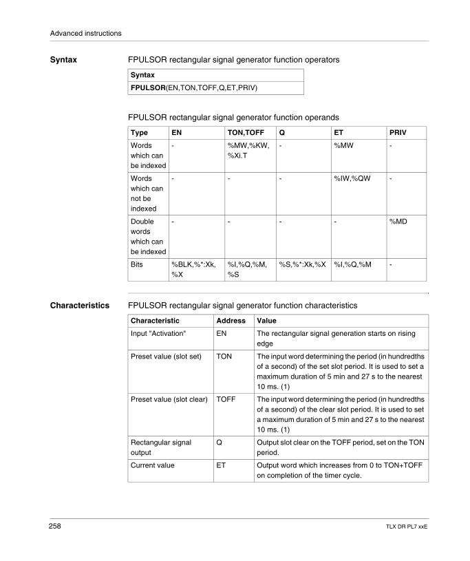
Advanced instructions
Syntax FPULSOR rectangular signal generator function operators
FPULSOR rectangular signal generator function operands
Characteristics FPULSOR rectangular signal generator function characteristics
Syntax
FPULSOR(EN,TON,TOFF,Q,ET,PRIV)
Type EN TON,TOFF Q ET PRIV
Words which can be indexed
- %MW,%KW,%Xi.T
- %MW -
Words which can not be indexed
- - - %IW,%QW -
Double words which can be indexed
- - - - %MD
Bits %BLK,%*:Xk,%X
%I,%Q,%M, %S
%S,%*:Xk,%X %I,%Q,%M -
Characteristic Address Value
Input "Activation" EN The rectangular signal generation starts on rising edge
Preset value (slot set) TON The input word determining the period (in hundredths of a second) of the set slot period. It is used to set a maximum duration of 5 min and 27 s to the nearest 10 ms. (1)
Preset value (slot clear) TOFF The input word determining the period (in hundredths of a second) of the clear slot period. It is used to set a maximum duration of 5 min and 27 s to the nearest 10 ms. (1)
Rectangular signal output
Q Output slot clear on the TOFF period, set on the TON period.
Current value ET Output word which increases from 0 to TON+TOFF on completion of the timer cycle.
258 TLX DR PL7 xxE
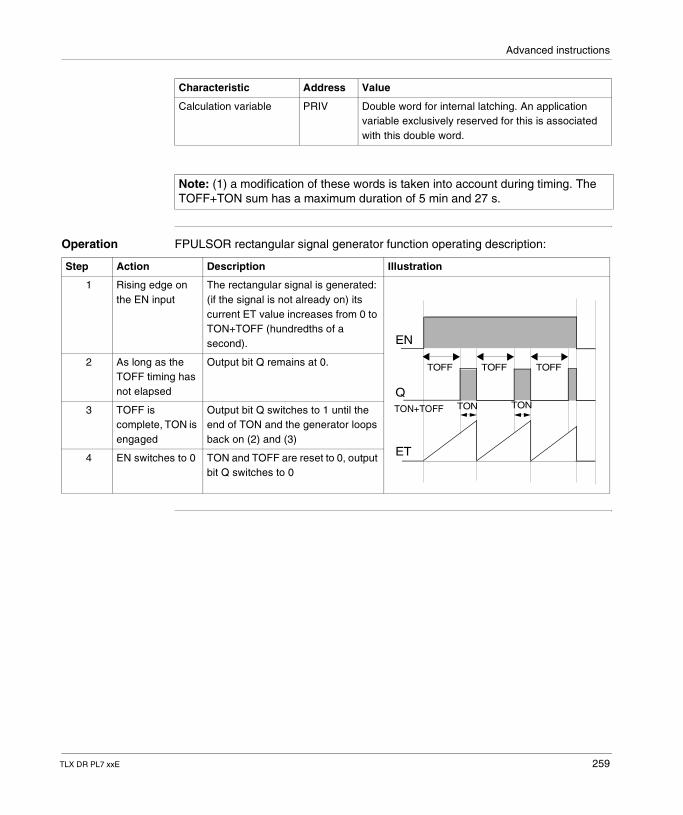
Advanced instructions
Operation FPULSOR rectangular signal generator function operating description:
Calculation variable PRIV Double word for internal latching. An application variable exclusively reserved for this is associated with this double word.
Note: (1) a modification of these words is taken into account during timing. The TOFF+TON sum has a maximum duration of 5 min and 27 s.
Characteristic Address Value
Step Action Description Illustration
1 Rising edge on the EN input
The rectangular signal is generated: (if the signal is not already on) its current ET value increases from 0 to TON+TOFF (hundredths of a second).
2 As long as the TOFF timing has not elapsed
Output bit Q remains at 0.
3 TOFF is complete, TON is engaged
Output bit Q switches to 1 until the end of TON and the generator loops back on (2) and (3)
4 EN switches to 0 TON and TOFF are reset to 0, output bit Q switches to 0
ET
Q
EN
TOFF TOFF
TON TON
TOFF
TON+TOFF
TLX DR PL7 xxE 259
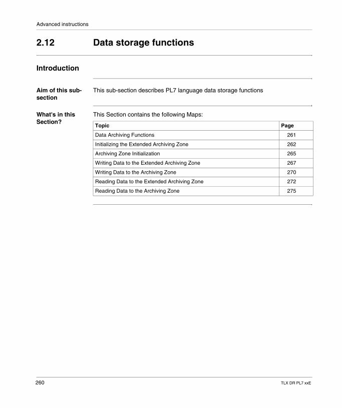
Advanced instructions
2.12 Data storage functions
Introduction
Aim of this sub-section
This sub-section describes PL7 language data storage functions
What's in this Section?
This Section contains the following Maps:
Topic Page
Data Archiving Functions 261
Initializing the Extended Archiving Zone 262
Archiving Zone Initialization 265
Writing Data to the Extended Archiving Zone 267
Writing Data to the Archiving Zone 270
Reading Data to the Extended Archiving Zone 272
Reading Data to the Archiving Zone 275
260 TLX DR PL7 xxE
Advanced instructions
Data Archiving Functions
At a Glance These functions allow the archiving of data by program in a dedicated zone for user memory cards.
Example of Application
� automatic storage of application data (status report log, history etc.) in the user memory card located in the memory slot in the PLC processor.
� saving of production acceptance tests in the same memory card.
Different Functions
6 functions allow data to be archived and restored.
The following functions are applied to any of the type 1 PCMCIA memory cards (memory cards located in slot 0 of the processor) and the type 3 cards (memory cards located in slot 1 of the processor). � SET_PCM_EXT: to initialize at a value all or part of the memory card's archiving
zone,� WRITE_PCM_EXT to write data into the archiving zone in the memory card,� READ_PCM_EXT: to read data in the memory card's archiving zone.
The following functions only apply to the type 1 PCMCIA memory card (memory cards located in slot 0 of the processor). � SET_PCMCIA: to initialize at a value all or part of the memory card's archiving
zone,� WRITE_PCMCIA to write data into the archiving zone in the memory card,� READ_PCMCIA: to read data in the memory card's archiving zone.
Note: These functions require:� PL7 V4.2 or above,� a PLC operating system version (SV), which is equal or above 5.2.
Note: access to data stored in the archiving zone of a memory card is only possible from the application in the PLC for these 6 base functions. A remote station CANNOT be accessed directly through a network or communication bus.
TLX DR PL7 xxE 261
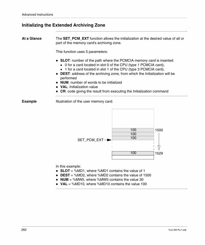
Advanced instructions
Initializing the Extended Archiving Zone
At a Glance The SET_PCM_EXT function allows the initialization at the desired value of all or part of the memory card's archiving zone.
This function uses 5 parameters:
� SLOT: number of the path where the PCMCIA memory card is inserted:� 0 for a card located in slot 0 of the CPU (type 1 PCMCIA card),� 1 for a card located in slot 1 of the CPU (type 3 PCMCIA card).
� DEST: address of the archiving zone, from which the Initialization will be performed
� NUM: number of words to be initialized� VAL: Initialization value� CR: code giving the result from executing the Initialization command
Example Illustration of the user memory card:
In this example:� SLOT = %MD1, where %MD1 contains the value of 1� DEST = %MD2, where %MD2 contains the value of 1500� NUM = %MW5, where %MW5 contains the value 30� VAL = %MD10, where %MD10 contains the value 100
1500
1529
100100100
100
SET_PCM_EXT
262 TLX DR PL7 xxE
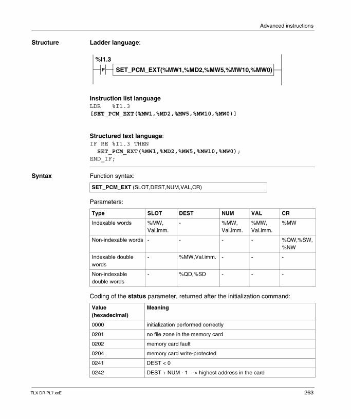
Advanced instructions
Structure Ladder language:
Instruction list languageLDR %I1.3[SET_PCM_EXT(%MW1,%MD2,%MW5,%MW10,%MW0)]
Structured text language:IF RE %I1.3 THEN SET_PCM_EXT(%MW1,%MD2,%MW5,%MW10,%MW0);END_IF;
Syntax Function syntax:
Parameters:
Coding of the status parameter, returned after the initialization command:
P SET_PCM_EXT(%MW1,%MD2,%MW5,%MW10,%MW0)
%I1.3
SET_PCM_EXT (SLOT,DEST,NUM,VAL,CR)
Type SLOT DEST NUM VAL CR
Indexable words %MW, Val.imm.
- %MW, Val.imm.
%MW, Val.imm.
%MW
Non-indexable words - - - - %QW,%SW, %NW
Indexable double words
- %MW,Val.imm. - - -
Non-indexable double words
- %QD,%SD - - -
Value(hexadecimal)
Meaning
0000 initialization performed correctly
0201 no file zone in the memory card
0202 memory card fault
0204 memory card write-protected
0241 DEST < 0
0242 DEST + NUM - 1 -> highest address in the card
TLX DR PL7 xxE 263
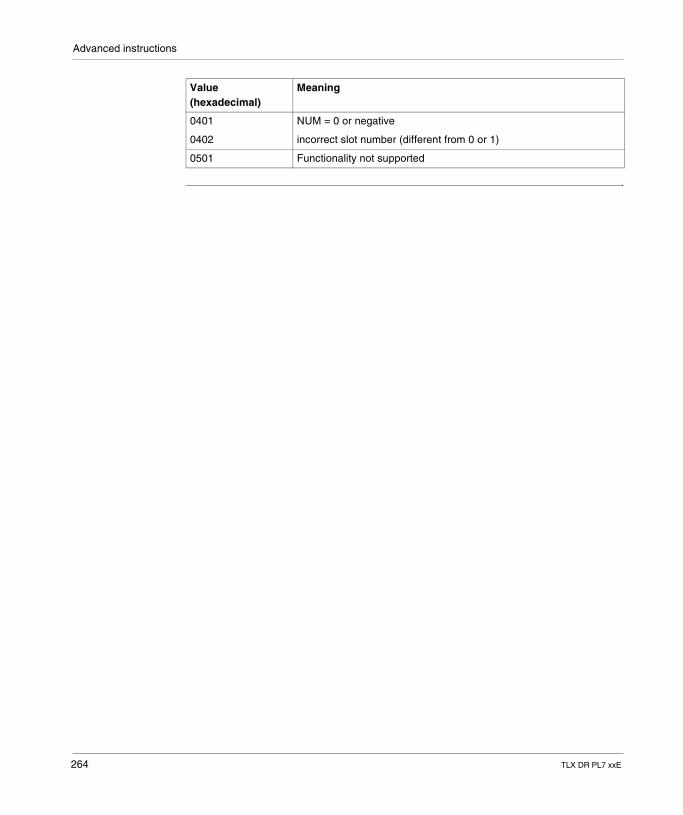
Advanced instructions
0401 NUM = 0 or negative
0402 incorrect slot number (different from 0 or 1)
0501 Functionality not supported
Value(hexadecimal)
Meaning
264 TLX DR PL7 xxE
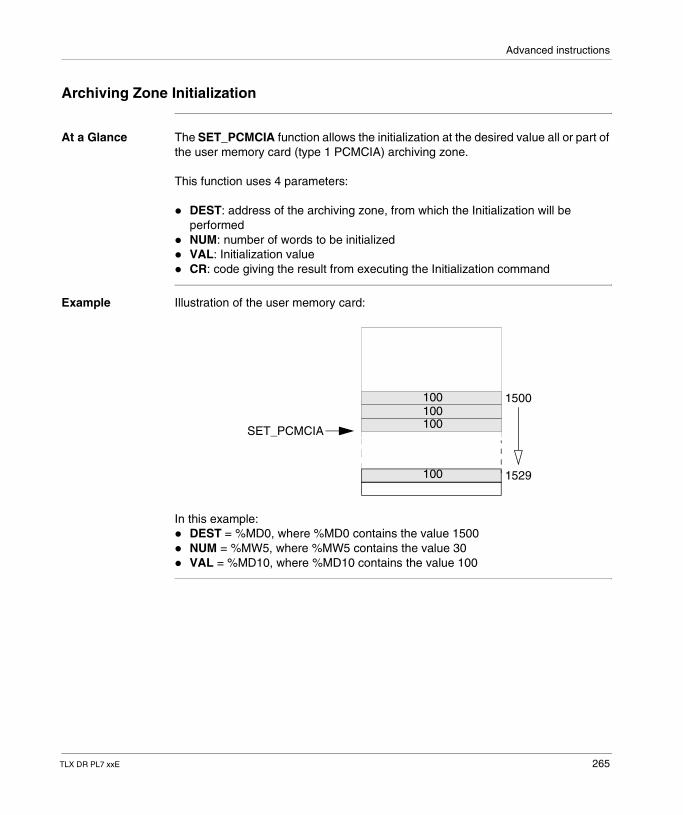
Advanced instructions
Archiving Zone Initialization
At a Glance The SET_PCMCIA function allows the initialization at the desired value all or part of the user memory card (type 1 PCMCIA) archiving zone.
This function uses 4 parameters:
� DEST: address of the archiving zone, from which the Initialization will be performed
� NUM: number of words to be initialized� VAL: Initialization value� CR: code giving the result from executing the Initialization command
Example Illustration of the user memory card:
In this example:� DEST = %MD0, where %MD0 contains the value 1500� NUM = %MW5, where %MW5 contains the value 30� VAL = %MD10, where %MD10 contains the value 100
1500
1529
100100100
100
SET_PCMCIA
TLX DR PL7 xxE 265
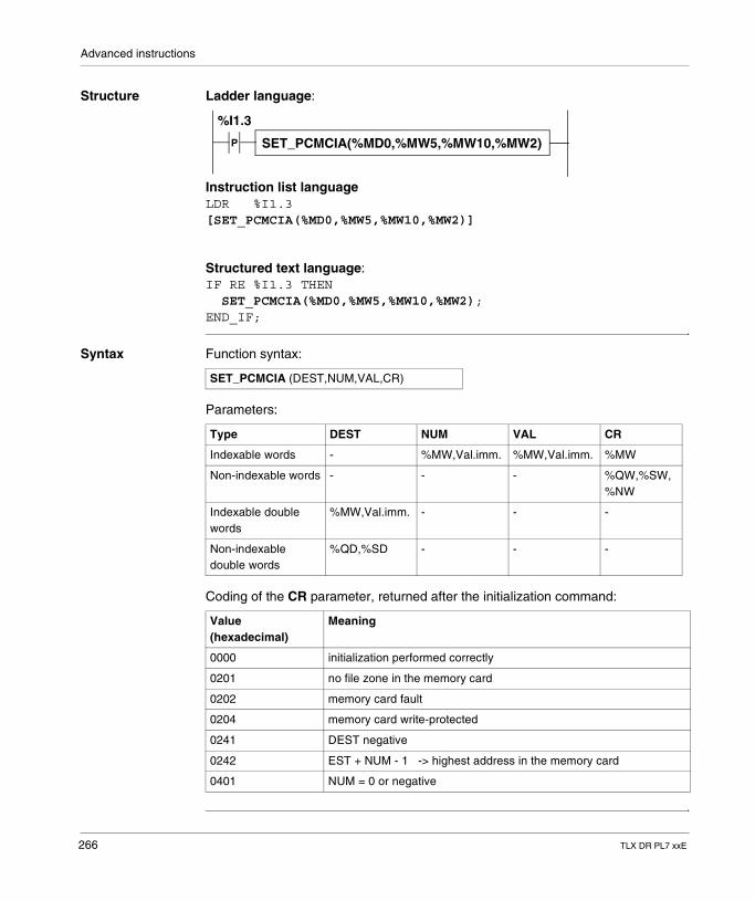
Advanced instructions
Structure Ladder language:
Instruction list languageLDR %I1.3[SET_PCMCIA(%MD0,%MW5,%MW10,%MW2)]
Structured text language:IF RE %I1.3 THEN SET_PCMCIA(%MD0,%MW5,%MW10,%MW2);END_IF;
Syntax Function syntax:
Parameters:
Coding of the CR parameter, returned after the initialization command:
P SET_PCMCIA(%MD0,%MW5,%MW10,%MW2)
%I1.3
SET_PCMCIA (DEST,NUM,VAL,CR)
Type DEST NUM VAL CR
Indexable words - %MW,Val.imm. %MW,Val.imm. %MW
Non-indexable words - - - %QW,%SW,%NW
Indexable double words
%MW,Val.imm. - - -
Non-indexable double words
%QD,%SD - - -
Value(hexadecimal)
Meaning
0000 initialization performed correctly
0201 no file zone in the memory card
0202 memory card fault
0204 memory card write-protected
0241 DEST negative
0242 EST + NUM - 1 -> highest address in the memory card
0401 NUM = 0 or negative
266 TLX DR PL7 xxE
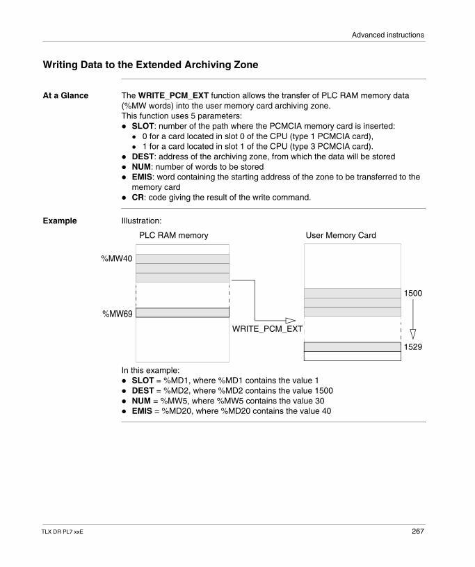
Advanced instructions
Writing Data to the Extended Archiving Zone
At a Glance The WRITE_PCM_EXT function allows the transfer of PLC RAM memory data (%MW words) into the user memory card archiving zone.This function uses 5 parameters:� SLOT: number of the path where the PCMCIA memory card is inserted:
� 0 for a card located in slot 0 of the CPU (type 1 PCMCIA card),� 1 for a card located in slot 1 of the CPU (type 3 PCMCIA card).
� DEST: address of the archiving zone, from which the data will be stored� NUM: number of words to be stored� EMIS: word containing the starting address of the zone to be transferred to the
memory card� CR: code giving the result of the write command.
Example Illustration:
In this example:� SLOT = %MD1, where %MD1 contains the value 1� DEST = %MD2, where %MD2 contains the value 1500� NUM = %MW5, where %MW5 contains the value 30� EMIS = %MD20, where %MD20 contains the value 40
1500
1529
WRITE_PCM_EXT
PLC RAM memory User Memory Card
%MW40
%MW69
TLX DR PL7 xxE 267
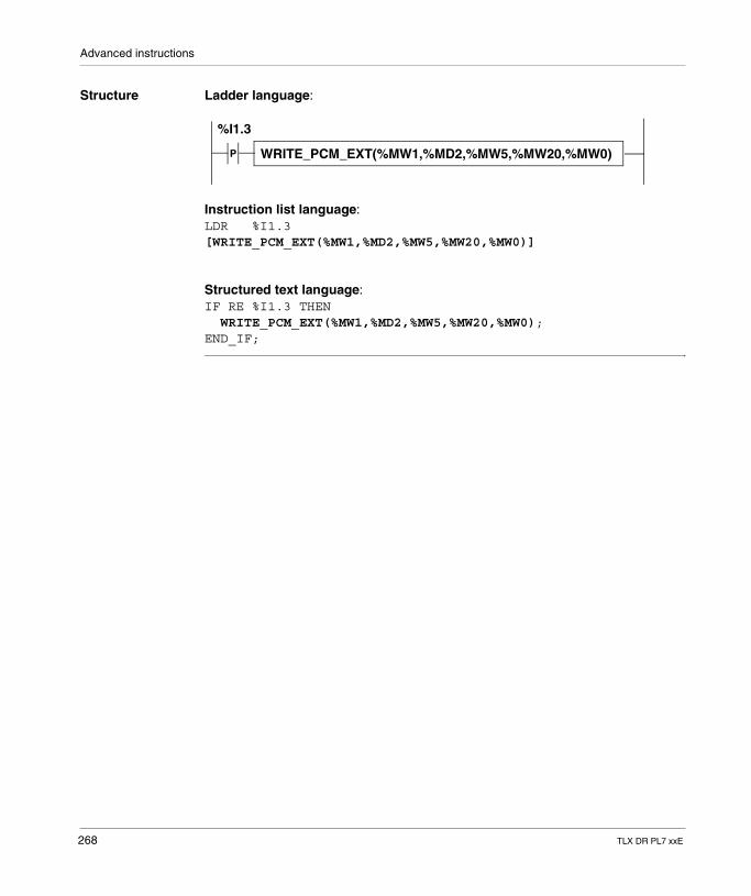
Advanced instructions
Structure Ladder language:
Instruction list language:LDR %I1.3[WRITE_PCM_EXT(%MW1,%MD2,%MW5,%MW20,%MW0)]
Structured text language:IF RE %I1.3 THEN WRITE_PCM_EXT(%MW1,%MD2,%MW5,%MW20,%MW0);END_IF;
P WRITE_PCM_EXT(%MW1,%MD2,%MW5,%MW20,%MW0)
%I1.3
268 TLX DR PL7 xxE
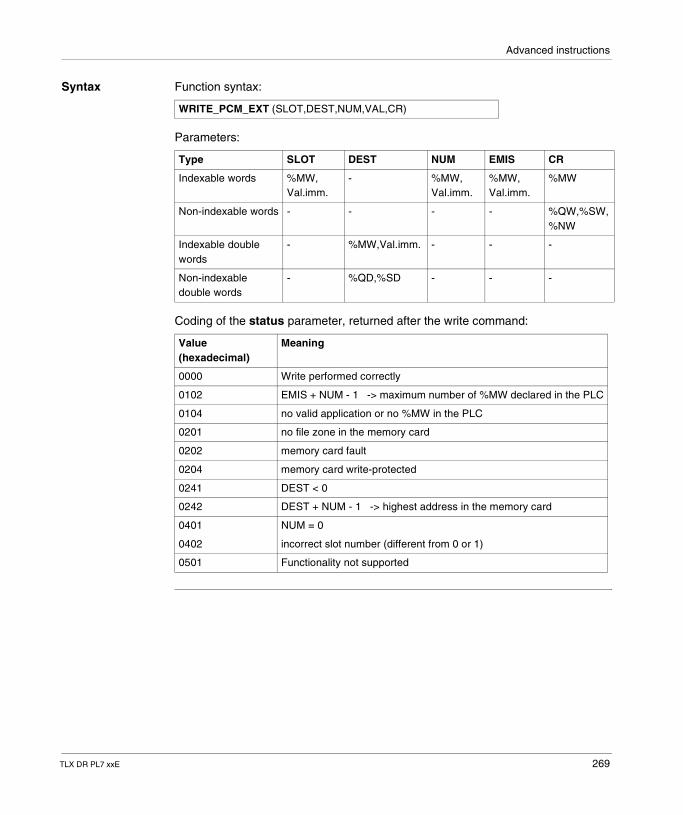
Advanced instructions
Syntax Function syntax:
Parameters:
Coding of the status parameter, returned after the write command:
WRITE_PCM_EXT (SLOT,DEST,NUM,VAL,CR)
Type SLOT DEST NUM EMIS CR
Indexable words %MW, Val.imm.
- %MW, Val.imm.
%MW, Val.imm.
%MW
Non-indexable words - - - - %QW,%SW, %NW
Indexable double words
- %MW,Val.imm. - - -
Non-indexable double words
- %QD,%SD - - -
Value(hexadecimal)
Meaning
0000 Write performed correctly
0102 EMIS + NUM - 1 -> maximum number of %MW declared in the PLC
0104 no valid application or no %MW in the PLC
0201 no file zone in the memory card
0202 memory card fault
0204 memory card write-protected
0241 DEST < 0
0242 DEST + NUM - 1 -> highest address in the memory card
0401 NUM = 0
0402 incorrect slot number (different from 0 or 1)
0501 Functionality not supported
TLX DR PL7 xxE 269
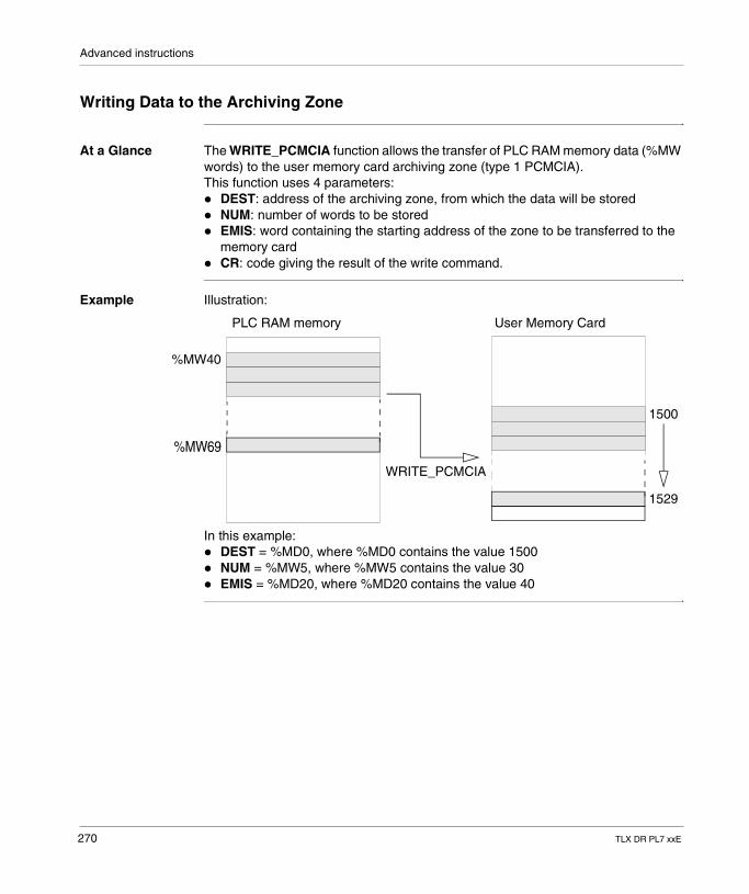
Advanced instructions
Writing Data to the Archiving Zone
At a Glance The WRITE_PCMCIA function allows the transfer of PLC RAM memory data (%MW words) to the user memory card archiving zone (type 1 PCMCIA).This function uses 4 parameters:� DEST: address of the archiving zone, from which the data will be stored� NUM: number of words to be stored� EMIS: word containing the starting address of the zone to be transferred to the
memory card� CR: code giving the result of the write command.
Example Illustration:
In this example:� DEST = %MD0, where %MD0 contains the value 1500� NUM = %MW5, where %MW5 contains the value 30� EMIS = %MD20, where %MD20 contains the value 40
1500
1529
WRITE_PCMCIA
PLC RAM memory User Memory Card
%MW40
%MW69
270 TLX DR PL7 xxE
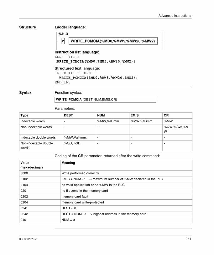
Advanced instructions
Structure Ladder language:
Instruction list language:LDR %I1.3[WRITE_PCMCIA(%MD0,%MW5,%MW20,%MW2)]
Structured text language:IF RE %I1.3 THEN WRITE_PCMCIA(%MD0,%MW5,%MW20,%MW2);END_IF;
Syntax Function syntax:
Parameters:
Coding of the CR parameter, returned after the write command:
P WRITE_PCMCIA(%MD0,%MW5,%MW20,%MW2)
%I1.3
WRITE_PCMCIA (DEST,NUM,EMIS,CR)
Type DEST NUM EMIS CR
Indexable words - %MW,Val.imm. %MW,Val.imm. %MW
Non-indexable words - - - %QW,%SW,%NW
Indexable double words %MW,Val.imm. - - -
Non-indexable double words
%QD,%SD - - -
Value(hexadecimal)
Meaning
0000 Write performed correctly
0102 EMIS + NUM - 1 -> maximum number of %MW declared in the PLC
0104 no valid application or no %MW in the PLC
0201 no file zone in the memory card
0202 memory card fault
0204 memory card write-protected
0241 DEST < 0
0242 DEST + NUM - 1 -> highest address in the memory card
0401 NUM = 0
TLX DR PL7 xxE 271
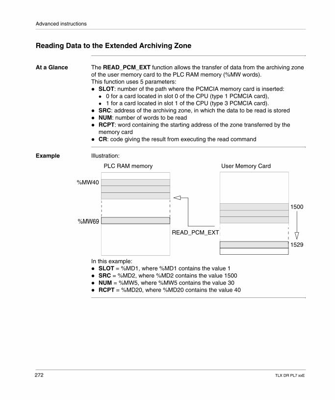
Advanced instructions
Reading Data to the Extended Archiving Zone
At a Glance The READ_PCM_EXT function allows the transfer of data from the archiving zone of the user memory card to the PLC RAM memory (%MW words).This function uses 5 parameters:� SLOT: number of the path where the PCMCIA memory card is inserted:
� 0 for a card located in slot 0 of the CPU (type 1 PCMCIA card),� 1 for a card located in slot 1 of the CPU (type 3 PCMCIA card).
� SRC: address of the archiving zone, in which the data to be read is stored� NUM: number of words to be read� RCPT: word containing the starting address of the zone transferred by the
memory card� CR: code giving the result from executing the read command
Example Illustration:
In this example:� SLOT = %MD1, where %MD1 contains the value 1� SRC = %MD2, where %MD2 contains the value 1500� NUM = %MW5, where %MW5 contains the value 30� RCPT = %MD20, where %MD20 contains the value 40
1500
1529
READ_PCM_EXT
PLC RAM memory User Memory Card
%MW40
%MW69
272 TLX DR PL7 xxE
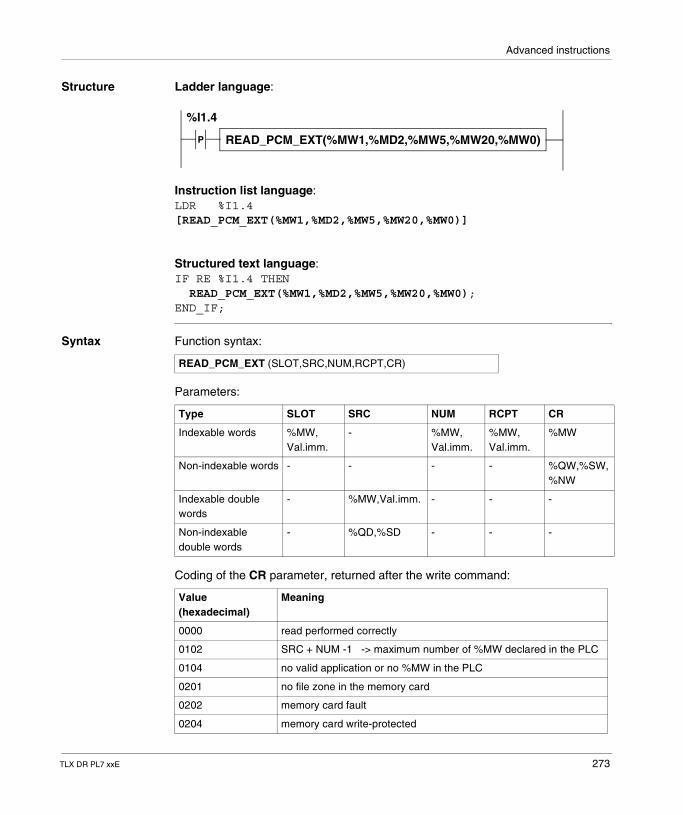
Advanced instructions
Structure Ladder language:
Instruction list language:LDR %I1.4[READ_PCM_EXT(%MW1,%MD2,%MW5,%MW20,%MW0)]
Structured text language:IF RE %I1.4 THEN READ_PCM_EXT(%MW1,%MD2,%MW5,%MW20,%MW0);END_IF;
Syntax Function syntax:
Parameters:
Coding of the CR parameter, returned after the write command:
P READ_PCM_EXT(%MW1,%MD2,%MW5,%MW20,%MW0)
%I1.4
READ_PCM_EXT (SLOT,SRC,NUM,RCPT,CR)
Type SLOT SRC NUM RCPT CR
Indexable words %MW, Val.imm.
- %MW, Val.imm.
%MW, Val.imm.
%MW
Non-indexable words - - - - %QW,%SW, %NW
Indexable double words
- %MW,Val.imm. - - -
Non-indexable double words
- %QD,%SD - - -
Value(hexadecimal)
Meaning
0000 read performed correctly
0102 SRC + NUM -1 -> maximum number of %MW declared in the PLC
0104 no valid application or no %MW in the PLC
0201 no file zone in the memory card
0202 memory card fault
0204 memory card write-protected
TLX DR PL7 xxE 273
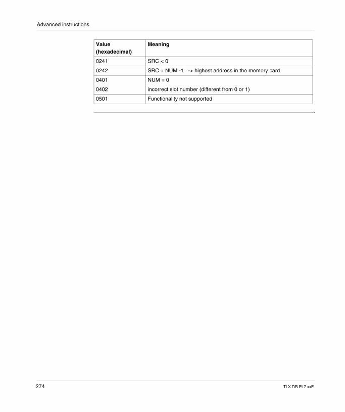
Advanced instructions
0241 SRC < 0
0242 SRC + NUM -1 -> highest address in the memory card
0401 NUM = 0
0402 incorrect slot number (different from 0 or 1)
0501 Functionality not supported
Value(hexadecimal)
Meaning
274 TLX DR PL7 xxE
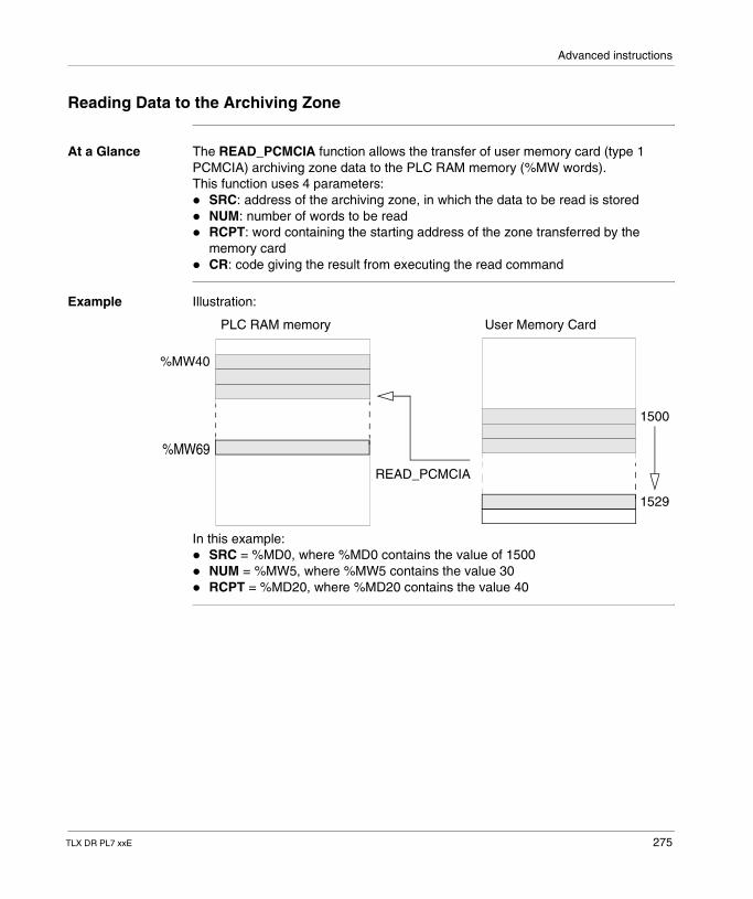
Advanced instructions
Reading Data to the Archiving Zone
At a Glance The READ_PCMCIA function allows the transfer of user memory card (type 1 PCMCIA) archiving zone data to the PLC RAM memory (%MW words).This function uses 4 parameters:� SRC: address of the archiving zone, in which the data to be read is stored� NUM: number of words to be read� RCPT: word containing the starting address of the zone transferred by the
memory card� CR: code giving the result from executing the read command
Example Illustration:
In this example:� SRC = %MD0, where %MD0 contains the value of 1500� NUM = %MW5, where %MW5 contains the value 30� RCPT = %MD20, where %MD20 contains the value 40
1500
1529
READ_PCMCIA
PLC RAM memory User Memory Card
%MW40
%MW69
TLX DR PL7 xxE 275
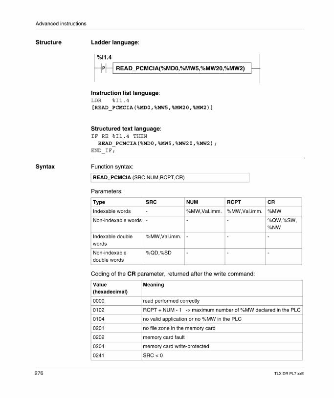
Advanced instructions
Structure Ladder language:
Instruction list language:LDR %I1.4[READ_PCMCIA(%MD0,%MW5,%MW20,%MW2)]
Structured text language:IF RE %I1.4 THEN READ_PCMCIA(%MD0,%MW5,%MW20,%MW2);END_IF;
Syntax Function syntax:
Parameters:
Coding of the CR parameter, returned after the write command:
P READ_PCMCIA(%MD0,%MW5,%MW20,%MW2)
%I1.4
READ_PCMCIA (SRC,NUM,RCPT,CR)
Type SRC NUM RCPT CR
Indexable words - %MW,Val.imm. %MW,Val.imm. %MW
Non-indexable words - - - %QW,%SW,%NW
Indexable double words
%MW,Val.imm. - - -
Non-indexable double words
%QD,%SD - - -
Value(hexadecimal)
Meaning
0000 read performed correctly
0102 RCPT + NUM - 1 -> maximum number of %MW declared in the PLC
0104 no valid application or no %MW in the PLC
0201 no file zone in the memory card
0202 memory card fault
0204 memory card write-protected
0241 SRC < 0
276 TLX DR PL7 xxE
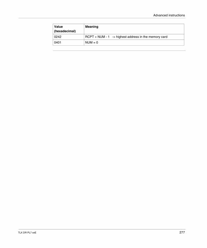
Advanced instructions
0242 RCPT + NUM - 1 -> highest address in the memory card
0401 NUM = 0
Value(hexadecimal)
Meaning
TLX DR PL7 xxE 277
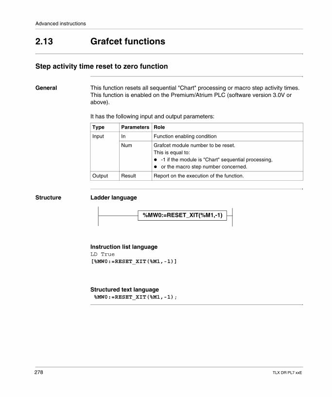
Advanced instructions
2.13 Grafcet functions
Step activity time reset to zero function
General This function resets all sequential "Chart" processing or macro step activity times.This function is enabled on the Premium/Atrium PLC (software version 3.0V or above).
It has the following input and output parameters:
Structure Ladder language
Instruction list languageLD True[%MW0:=RESET_XIT(%M1,-1)]
Structured text language %MW0:=RESET_XIT(%M1,-1);
Type Parameters Role
Input In Function enabling condition
Num Grafcet module number to be reset. This is equal to:� -1 if the module is "Chart" sequential processing,� or the macro step number concerned.
Output Result Report on the execution of the function.
%MW0:=RESET_XIT(%M1,-1)
278 TLX DR PL7 xxE
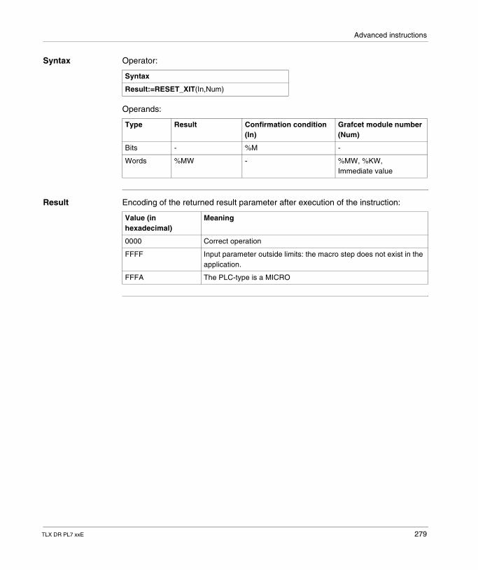
Advanced instructions
Syntax Operator:
Operands:
Result Encoding of the returned result parameter after execution of the instruction:
Syntax
Result:=RESET_XIT(In,Num)
Type Result Confirmation condition (In)
Grafcet module number (Num)
Bits - %M -
Words %MW - %MW, %KW, Immediate value
Value (in hexadecimal)
Meaning
0000 Correct operation
FFFF Input parameter outside limits: the macro step does not exist in the application.
FFFA The PLC-type is a MICRO
TLX DR PL7 xxE 279

Advanced instructions
280 TLX DR PL7 xxE
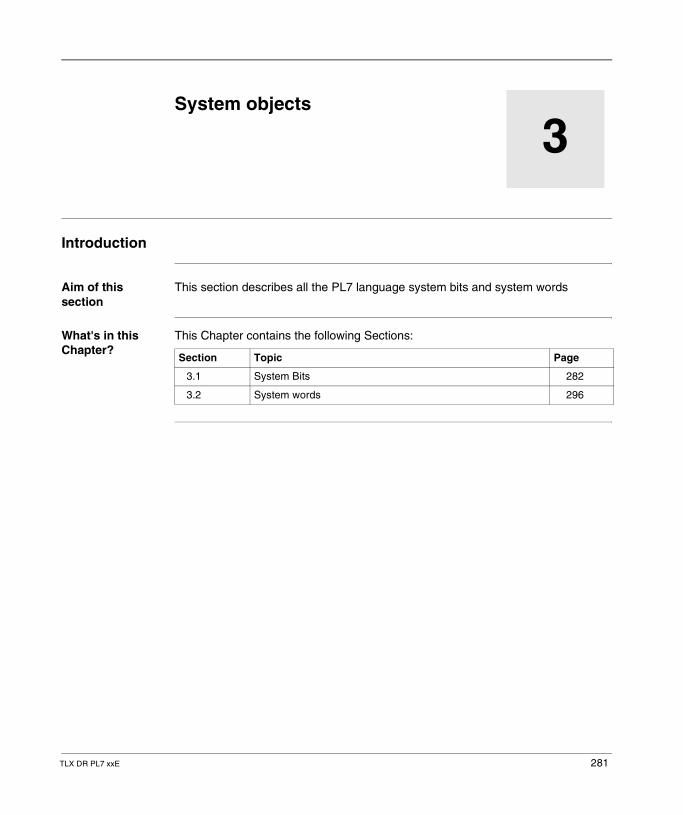
TLX DR PL7 xxE
3
System objectsIntroduction
Aim of this section
This section describes all the PL7 language system bits and system words
What's in this Chapter?
This Chapter contains the following Sections:
Section Topic Page
3.1 System Bits 282
3.2 System words 296
281
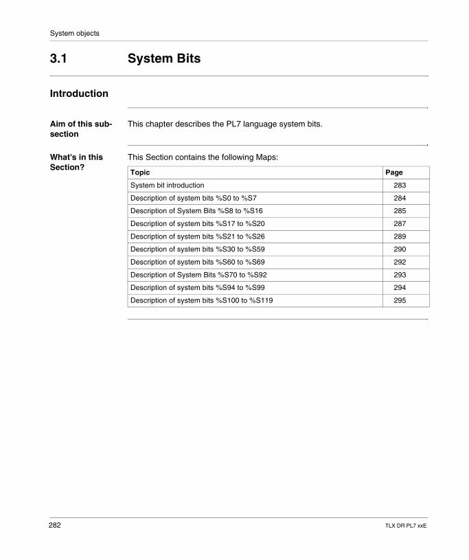
System objects
3.1 System Bits
Introduction
Aim of this sub-section
This chapter describes the PL7 language system bits.
What's in this Section?
This Section contains the following Maps:
Topic Page
System bit introduction 283
Description of system bits %S0 to %S7 284
Description of System Bits %S8 to %S16 285
Description of system bits %S17 to %S20 287
Description of system bits %S21 to %S26 289
Description of system bits %S30 to %S59 290
Description of system bits %S60 to %S69 292
Description of System Bits %S70 to %S92 293
Description of system bits %S94 to %S99 294
Description of system bits %S100 to %S119 295
282 TLX DR PL7 xxE
System objects
System bit introduction
General The TSX 37 and TSX 57 PLCs use %Si system bits which indicate the state of the PLC, or they can be used to operate its functioning.This bits can be tested in the user program to detect any function event before starting a set processing procedure. Some bits must be reset to their initial or usual state by program. However, the system bits, which are reset to their initial or usual state by the system, must not be done so by program or by the terminal.
TLX DR PL7 xxE 283
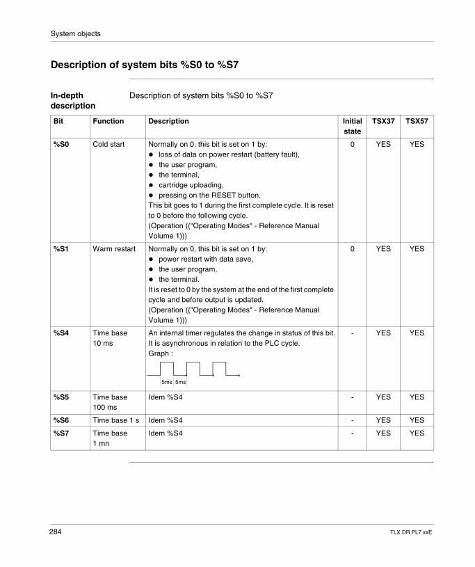
System objects
Description of system bits %S0 to %S7
In-depth description
Description of system bits %S0 to %S7
Bit Function Description Initial state
TSX37 TSX57
%S0 Cold start Normally on 0, this bit is set on 1 by:� loss of data on power restart (battery fault),� the user program,� the terminal,� cartridge uploading,� pressing on the RESET button.This bit goes to 1 during the first complete cycle. It is reset to 0 before the following cycle.(Operation (("Operating Modes" - Reference Manual Volume 1)))
0 YES YES
%S1 Warm restart Normally on 0, this bit is set on 1 by:� power restart with data save,� the user program,� the terminal.It is reset to 0 by the system at the end of the first complete cycle and before output is updated.(Operation (("Operating Modes" - Reference Manual Volume 1)))
0 YES YES
%S4 Time base 10 ms
An internal timer regulates the change in status of this bit.It is asynchronous in relation to the PLC cycle.Graph :
- YES YES
%S5 Time base 100 ms
Idem %S4 - YES YES
%S6 Time base 1 s Idem %S4 - YES YES
%S7 Time base 1 mn
Idem %S4 - YES YES
5ms 5ms
284 TLX DR PL7 xxE
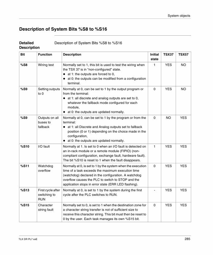
System objects
Description of System Bits %S8 to %S16
Detailed Description
Description of System Bits %S8 to %S16
Bit Function Description Initial state
TSX37 TSX57
%S8 Wiring test Normally set to 1, this bit is used to test the wiring when the TSX 37 is in "non-configured" state.� at 1: the outputs are forced to 0,� at 0: the outputs can be modified from a configuration
terminal.
1 YES NO
%S9 Setting outputs to 0
Normally at 0, can be set to 1 by the output program or from the terminal:� at 1: all discrete and analog outputs are set to 0,
whatever the fallback mode configured for each module,
� at 0: the outputs are updated normally.
0 YES NO
%S9 Outputs on all buses to fallback
Normally at 0, can be set to 1 by the program or from the terminal:� at 1: all Discrete and Analog outputs set to fallback
position (0 or 1) depending on the choice made in the configuration,
� at 0: the outputs are updated normally.
0 NO YES
%S10 I/O fault Normally at 1. Is set to 0 when an I/O fault is detected on an in-rack module or a remote module (FIPIO) (non-compliant configuration, exchange fault, hardware fault). The bit %S10 is reset to 1 when the fault disappears.
1 YES YES
%S11 Watchdog overflow
Normally at 0, is set to 1 by the system when the execution time of a task exceeds the maximum execution time (watchdog) declared in the configuration. A watchdog overflow causes the PLC to switch to STOP and the application stops in error state (ERR LED flashing).
0 YES YES
%S13 First cycle after switching to RUN
Normally at 0, is set to 1 by the system during the first cycle after the PLC switches to RUN.
- YES YES
%S15 Character string fault
Normally set to 0, is set to 1 when the destination zone for a character string transfer is not of sufficient size to receive this character string. This bit must then be reset to 0 by the user. Each task manages its own %S15 bit.
0 YES YES
TLX DR PL7 xxE 285
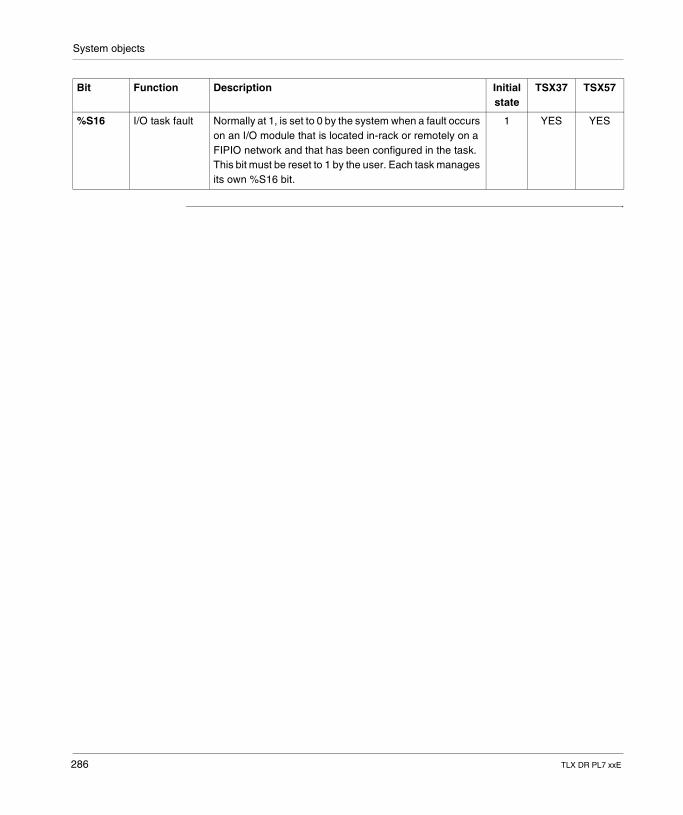
System objects
%S16 I/O task fault Normally at 1, is set to 0 by the system when a fault occurs on an I/O module that is located in-rack or remotely on a FIPIO network and that has been configured in the task. This bit must be reset to 1 by the user. Each task manages its own %S16 bit.
1 YES YES
Bit Function Description Initial state
TSX37 TSX57
286 TLX DR PL7 xxE
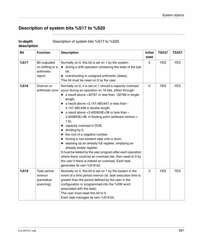
System objects
Description of system bits %S17 to %S20
In-depth description
Description of system bits %S17 to %S20
Bit Function Description Initial state
TSX37 TSX57
%S17 Bit outputted on shifting or a arithmetic report.
Normally on 0, this bit is set on 1 by the system:� during a shift operation containing the state of the last
bit,� overshooting in unsigned arithmetic (dates).This bit must be reset on 0 by the user.
0 YES YES
%S18 Overrun or arithmetic error
Normally on 0, it is set on 1 should a capacity overload occur during an operation on 16 bits, either through:� a result above +32767 or less than –32768 in single
length,� a result above +2,147,483,647 or less than -
2.147.483.648 in double length,� a result above +3.402824E+38 or less than –
3.402824E+38, in floating point (software version > 1.0),
� capacity overload in DCB,� dividing by 0,� the root of a negative number,� forcing a non-existent step onto a drum.� stacking up an already full register, emptying an
already empty register.It must be tested by the user program after each operation where there could be an overload risk, then reset to 0 by the user if there is indeed an overload. Each task generates its own %S18 bit.
0 YES YES
%S19 Task period overrun (periodical scanning)
Normally on 0, this bit is set on 1 by the system in the event of a time period overrun (ie. task execution time is greater than the period defined by the user in the configuration or programmed into the %SW word associated with the task).The user must reset this bit to 0.Each task manages its own %S19 bit.
0 YES YES
TLX DR PL7 xxE 287
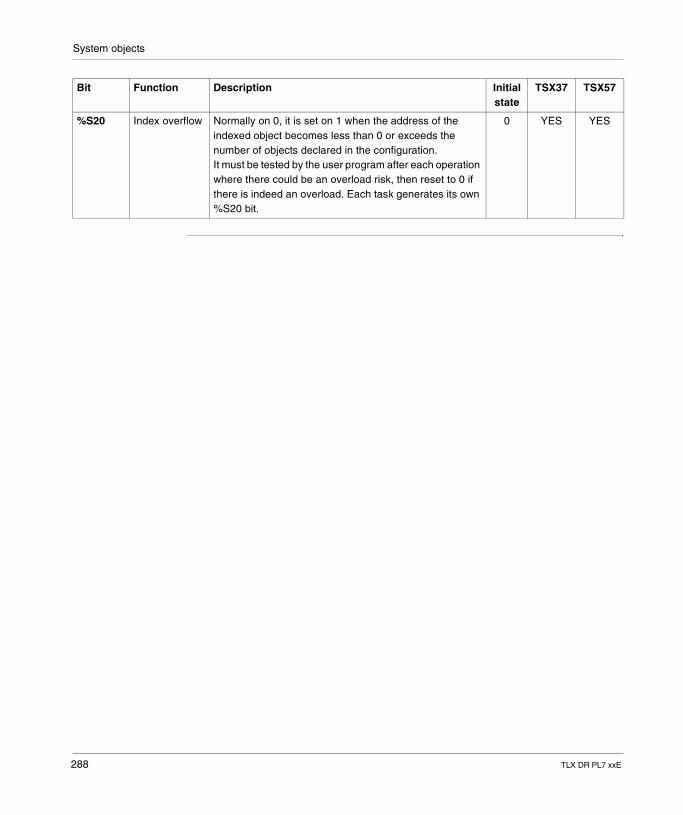
System objects
%S20 Index overflow Normally on 0, it is set on 1 when the address of the indexed object becomes less than 0 or exceeds the number of objects declared in the configuration.It must be tested by the user program after each operation where there could be an overload risk, then reset to 0 if there is indeed an overload. Each task generates its own %S20 bit.
0 YES YES
Bit Function Description Initial state
TSX37 TSX57
288 TLX DR PL7 xxE
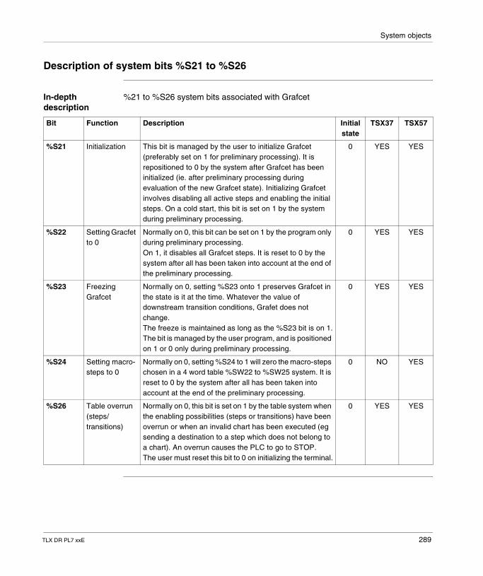
System objects
Description of system bits %S21 to %S26
In-depth description
%21 to %S26 system bits associated with Grafcet
Bit Function Description Initial state
TSX37 TSX57
%S21 Initialization This bit is managed by the user to initialize Grafcet (preferably set on 1 for preliminary processing). It is repositioned to 0 by the system after Grafcet has been initialized (ie. after preliminary processing during evaluation of the new Grafcet state). Initializing Grafcet involves disabling all active steps and enabling the initial steps. On a cold start, this bit is set on 1 by the system during preliminary processing.
0 YES YES
%S22 Setting Gracfet to 0
Normally on 0, this bit can be set on 1 by the program only during preliminary processing.On 1, it disables all Grafcet steps. It is reset to 0 by the system after all has been taken into account at the end of the preliminary processing.
0 YES YES
%S23 Freezing Grafcet
Normally on 0, setting %S23 onto 1 preserves Grafcet in the state is it at the time. Whatever the value of downstream transition conditions, Grafet does not change.The freeze is maintained as long as the %S23 bit is on 1.The bit is managed by the user program, and is positioned on 1 or 0 only during preliminary processing.
0 YES YES
%S24 Setting macro-steps to 0
Normally on 0, setting %S24 to 1 will zero the macro-steps chosen in a 4 word table %SW22 to %SW25 system. It is reset to 0 by the system after all has been taken into account at the end of the preliminary processing.
0 NO YES
%S26 Table overrun (steps/transitions)
Normally on 0, this bit is set on 1 by the table system when the enabling possibilities (steps or transitions) have been overrun or when an invalid chart has been executed (eg sending a destination to a step which does not belong to a chart). An overrun causes the PLC to go to STOP.The user must reset this bit to 0 on initializing the terminal.
0 YES YES
TLX DR PL7 xxE 289
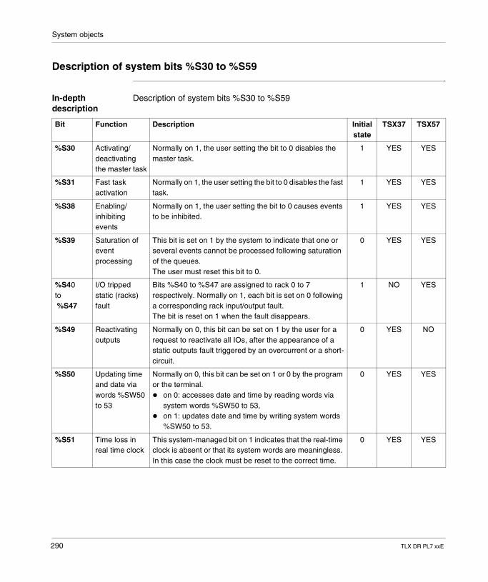
System objects
Description of system bits %S30 to %S59
In-depth description
Description of system bits %S30 to %S59
Bit Function Description Initial state
TSX37 TSX57
%S30 Activating/deactivating the master task
Normally on 1, the user setting the bit to 0 disables the master task.
1 YES YES
%S31 Fast task activation
Normally on 1, the user setting the bit to 0 disables the fast task.
1 YES YES
%S38 Enabling/inhibiting events
Normally on 1, the user setting the bit to 0 causes events to be inhibited.
1 YES YES
%S39 Saturation of event processing
This bit is set on 1 by the system to indicate that one or several events cannot be processed following saturation of the queues.The user must reset this bit to 0.
0 YES YES
%S40to %S47
I/O tripped static (racks) fault
Bits %S40 to %S47 are assigned to rack 0 to 7 respectively. Normally on 1, each bit is set on 0 following a corresponding rack input/output fault.The bit is reset on 1 when the fault disappears.
1 NO YES
%S49 Reactivating outputs
Normally on 0, this bit can be set on 1 by the user for a request to reactivate all IOs, after the appearance of a static outputs fault triggered by an overcurrent or a short-circuit.
0 YES NO
%S50 Updating time and date via words %SW50 to 53
Normally on 0, this bit can be set on 1 or 0 by the program or the terminal.� on 0: accesses date and time by reading words via
system words %SW50 to 53,� on 1: updates date and time by writing system words
%SW50 to 53.
0 YES YES
%S51 Time loss in real time clock
This system-managed bit on 1 indicates that the real-time clock is absent or that its system words are meaningless. In this case the clock must be reset to the correct time.
0 YES YES
290 TLX DR PL7 xxE
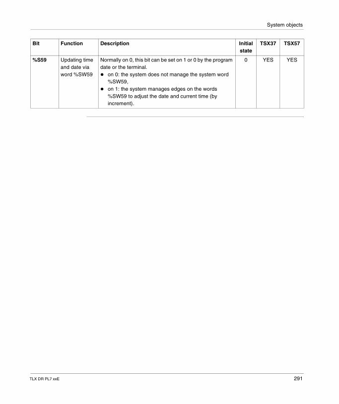
System objects
%S59 Updating time and date via word %SW59
Normally on 0, this bit can be set on 1 or 0 by the program date or the terminal.� on 0: the system does not manage the system word
%SW59,� on 1: the system manages edges on the words
%SW59 to adjust the date and current time (by increment).
0 YES YES
Bit Function Description Initial state
TSX37 TSX57
TLX DR PL7 xxE 291
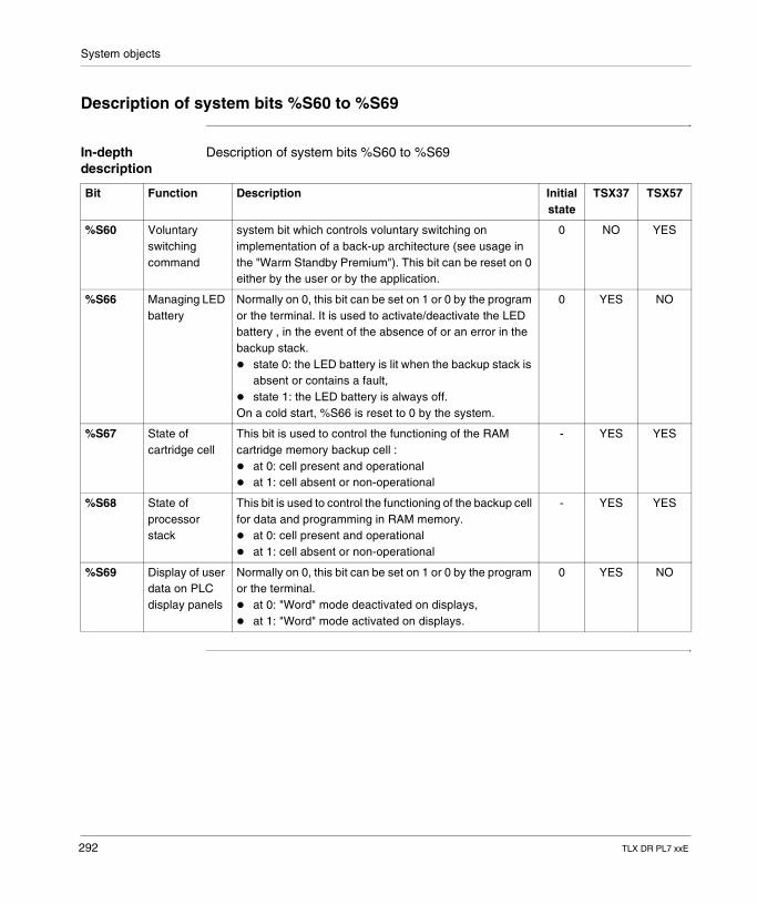
System objects
Description of system bits %S60 to %S69
In-depth description
Description of system bits %S60 to %S69
Bit Function Description Initial state
TSX37 TSX57
%S60 Voluntary switching command
system bit which controls voluntary switching on implementation of a back-up architecture (see usage in the "Warm Standby Premium"). This bit can be reset on 0 either by the user or by the application.
0 NO YES
%S66 Managing LED battery
Normally on 0, this bit can be set on 1 or 0 by the program or the terminal. It is used to activate/deactivate the LED battery , in the event of the absence of or an error in the backup stack.� state 0: the LED battery is lit when the backup stack is
absent or contains a fault,� state 1: the LED battery is always off.On a cold start, %S66 is reset to 0 by the system.
0 YES NO
%S67 State of cartridge cell
This bit is used to control the functioning of the RAM cartridge memory backup cell :� at 0: cell present and operational� at 1: cell absent or non-operational
- YES YES
%S68 State of processor stack
This bit is used to control the functioning of the backup cell for data and programming in RAM memory.� at 0: cell present and operational� at 1: cell absent or non-operational
- YES YES
%S69 Display of user data on PLC display panels
Normally on 0, this bit can be set on 1 or 0 by the program or the terminal.� at 0: "Word" mode deactivated on displays,� at 1: "Word" mode activated on displays.
0 YES NO
292 TLX DR PL7 xxE
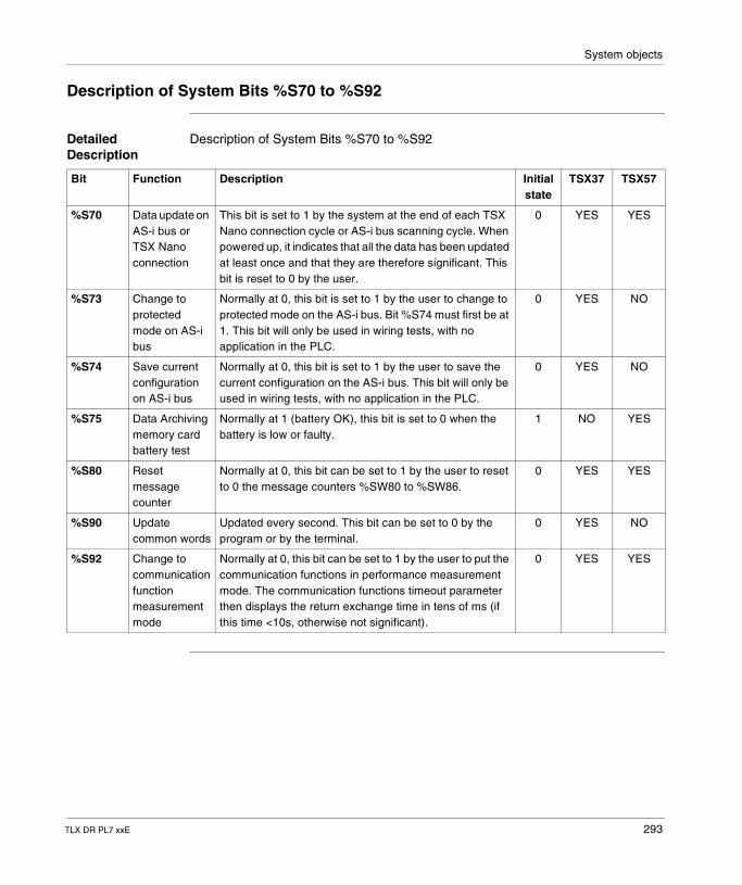
System objects
Description of System Bits %S70 to %S92
Detailed Description
Description of System Bits %S70 to %S92
Bit Function Description Initial state
TSX37 TSX57
%S70 Data update on AS-i bus or TSX Nano connection
This bit is set to 1 by the system at the end of each TSX Nano connection cycle or AS-i bus scanning cycle. When powered up, it indicates that all the data has been updated at least once and that they are therefore significant. This bit is reset to 0 by the user.
0 YES YES
%S73 Change to protected mode on AS-i bus
Normally at 0, this bit is set to 1 by the user to change to protected mode on the AS-i bus. Bit %S74 must first be at 1. This bit will only be used in wiring tests, with no application in the PLC.
0 YES NO
%S74 Save current configuration on AS-i bus
Normally at 0, this bit is set to 1 by the user to save the current configuration on the AS-i bus. This bit will only be used in wiring tests, with no application in the PLC.
0 YES NO
%S75 Data Archiving memory card battery test
Normally at 1 (battery OK), this bit is set to 0 when the battery is low or faulty.
1 NO YES
%S80 Reset message counter
Normally at 0, this bit can be set to 1 by the user to reset to 0 the message counters %SW80 to %SW86.
0 YES YES
%S90 Update common words
Updated every second. This bit can be set to 0 by the program or by the terminal.
0 YES NO
%S92 Change to communication function measurement mode
Normally at 0, this bit can be set to 1 by the user to put the communication functions in performance measurement mode. The communication functions timeout parameter then displays the return exchange time in tens of ms (if this time <10s, otherwise not significant).
0 YES YES
TLX DR PL7 xxE 293
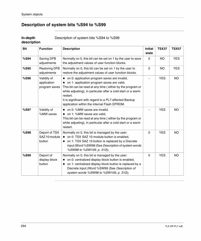
System objects
Description of system bits %S94 to %S99
In-depth description
Description of system bits %S94 to %S99
Bit Function Description Initial state
TSX37 TSX57
%S94 Saving DFB adjustments
Normally on 0, this bit can be set on 1 by the user to save the adjustment values of user function blocks.
0 NO YES
%S95 Restoring DFB adjustments
Normally on 0, this bit can be set on 1 by the user to restore the adjustment values of user function blocks.
0 NO YES
%S96 Validity of application program saves
� on 0: application program saves are invalid,� on 1: application program saves are valid,This bit can be read at any time ( either by the program or while adjusting), in particular after a cold start or a warm restart.It is significant with regard to a PL7-effected Backup application within the internal Flash EPROM.
- YES NO
%S97 Validity of %MW saves
� on 0: %MW saves are invalid,� on 1: %MW saves are valid,This bit can be read at any time ( either by the program or while adjusting), in particular after a cold start or a warm restart.
- YES NO
%S98 Deport of TSX SAZ 10 module button
Normally on 0, this bit is managed by the user:� on 0: TSX SAZ 10 module button is enabled,� on 1: TSX SAZ 10 button is replaced by a Discrete
input (Word %SW98 (See Description of system words %SW98 to %SW109, p. 312)).
0 YES NO
%S99 Deport of display block button
Normally on 0, this bit is managed by the user:� on 0: centralized display block button is enabled,� on 1: centralized display block button is replaced by a
Discrete input (Word %SW99 (See Description of system words %SW98 to %SW109, p. 312)).
0 YES NO
294 TLX DR PL7 xxE
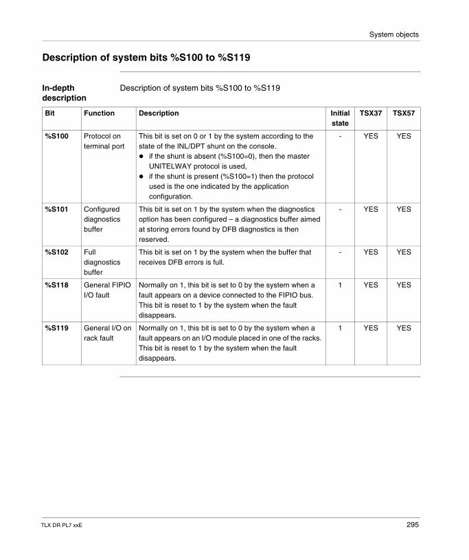
System objects
Description of system bits %S100 to %S119
In-depth description
Description of system bits %S100 to %S119
Bit Function Description Initial state
TSX37 TSX57
%S100 Protocol on terminal port
This bit is set on 0 or 1 by the system according to the state of the INL/DPT shunt on the console.� if the shunt is absent (%S100=0), then the master
UNITELWAY protocol is used,� if the shunt is present (%S100=1) then the protocol
used is the one indicated by the application configuration.
- YES YES
%S101 Configured diagnostics buffer
This bit is set on 1 by the system when the diagnostics option has been configured – a diagnostics buffer aimed at storing errors found by DFB diagnostics is then reserved.
- YES YES
%S102 Full diagnostics buffer
This bit is set on 1 by the system when the buffer that receives DFB errors is full.
- YES YES
%S118 General FIPIO I/O fault
Normally on 1, this bit is set to 0 by the system when a fault appears on a device connected to the FIPIO bus. This bit is reset to 1 by the system when the fault disappears.
1 YES YES
%S119 General I/O on rack fault
Normally on 1, this bit is set to 0 by the system when a fault appears on an I/O module placed in one of the racks. This bit is reset to 1 by the system when the fault disappears.
1 YES YES
TLX DR PL7 xxE 295
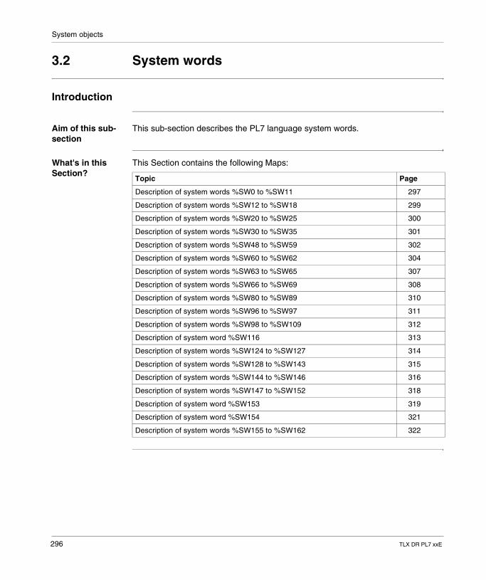
System objects
3.2 System words
Introduction
Aim of this sub-section
This sub-section describes the PL7 language system words.
What's in this Section?
This Section contains the following Maps:
Topic Page
Description of system words %SW0 to %SW11 297
Description of system words %SW12 to %SW18 299
Description of system words %SW20 to %SW25 300
Description of system words %SW30 to %SW35 301
Description of system words %SW48 to %SW59 302
Description of system words %SW60 to %SW62 304
Description of system words %SW63 to %SW65 307
Description of system words %SW66 to %SW69 308
Description of system words %SW80 to %SW89 310
Description of system words %SW96 to %SW97 311
Description of system words %SW98 to %SW109 312
Description of system word %SW116 313
Description of system words %SW124 to %SW127 314
Description of system words %SW128 to %SW143 315
Description of system words %SW144 to %SW146 316
Description of system words %SW147 to %SW152 318
Description of system word %SW153 319
Description of system word %SW154 321
Description of system words %SW155 to %SW162 322
296 TLX DR PL7 xxE
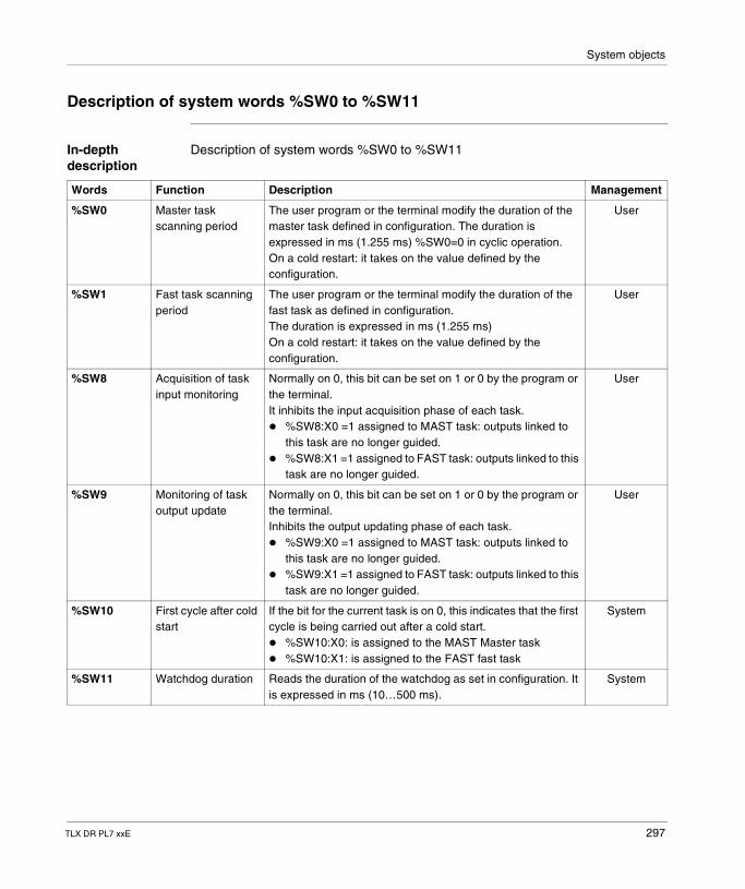
System objects
Description of system words %SW0 to %SW11
In-depth description
Description of system words %SW0 to %SW11
Words Function Description Management
%SW0 Master task scanning period
The user program or the terminal modify the duration of the master task defined in configuration. The duration is expressed in ms (1.255 ms) %SW0=0 in cyclic operation.On a cold restart: it takes on the value defined by the configuration.
User
%SW1 Fast task scanning period
The user program or the terminal modify the duration of the fast task as defined in configuration.The duration is expressed in ms (1.255 ms)On a cold restart: it takes on the value defined by the configuration.
User
%SW8 Acquisition of task input monitoring
Normally on 0, this bit can be set on 1 or 0 by the program or the terminal.It inhibits the input acquisition phase of each task.� %SW8:X0 =1 assigned to MAST task: outputs linked to
this task are no longer guided.� %SW8:X1 =1 assigned to FAST task: outputs linked to this
task are no longer guided.
User
%SW9 Monitoring of task output update
Normally on 0, this bit can be set on 1 or 0 by the program or the terminal.Inhibits the output updating phase of each task.� %SW9:X0 =1 assigned to MAST task: outputs linked to
this task are no longer guided.� %SW9:X1 =1 assigned to FAST task: outputs linked to this
task are no longer guided.
User
%SW10 First cycle after cold start
If the bit for the current task is on 0, this indicates that the first cycle is being carried out after a cold start.� %SW10:X0: is assigned to the MAST Master task� %SW10:X1: is assigned to the FAST fast task
System
%SW11 Watchdog duration Reads the duration of the watchdog as set in configuration. It is expressed in ms (10…500 ms).
System
TLX DR PL7 xxE 297
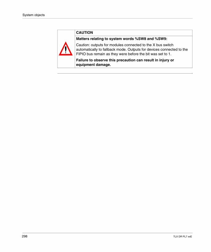
System objects
CAUTION
Matters relating to system words %SW8 and %SW9:
Caution: outputs for modules connected to the X bus switch automatically to fallback mode. Outputs for devices connected to the FIPIO bus remain as they were before the bit was set to 1.
Failure to observe this precaution can result in injury or equipment damage.
298 TLX DR PL7 xxE
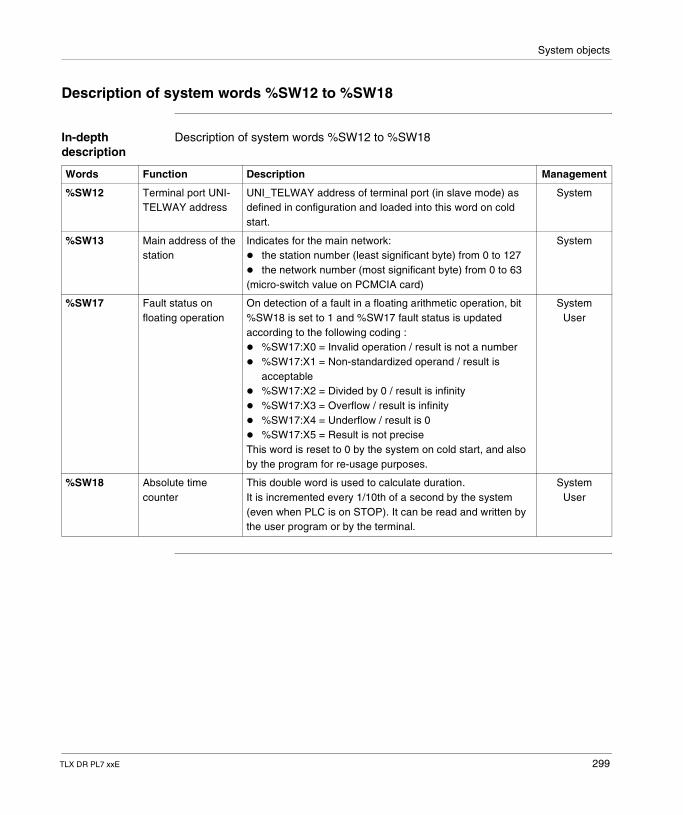
System objects
Description of system words %SW12 to %SW18
In-depth description
Description of system words %SW12 to %SW18
Words Function Description Management
%SW12 Terminal port UNI-TELWAY address
UNI_TELWAY address of terminal port (in slave mode) as defined in configuration and loaded into this word on cold start.
System
%SW13 Main address of the station
Indicates for the main network:� the station number (least significant byte) from 0 to 127� the network number (most significant byte) from 0 to 63(micro-switch value on PCMCIA card)
System
%SW17 Fault status on floating operation
On detection of a fault in a floating arithmetic operation, bit %SW18 is set to 1 and %SW17 fault status is updated according to the following coding :� %SW17:X0 = Invalid operation / result is not a number� %SW17:X1 = Non-standardized operand / result is
acceptable� %SW17:X2 = Divided by 0 / result is infinity� %SW17:X3 = Overflow / result is infinity� %SW17:X4 = Underflow / result is 0� %SW17:X5 = Result is not preciseThis word is reset to 0 by the system on cold start, and also by the program for re-usage purposes.
SystemUser
%SW18 Absolute time counter
This double word is used to calculate duration.It is incremented every 1/10th of a second by the system (even when PLC is on STOP). It can be read and written by the user program or by the terminal.
SystemUser
TLX DR PL7 xxE 299
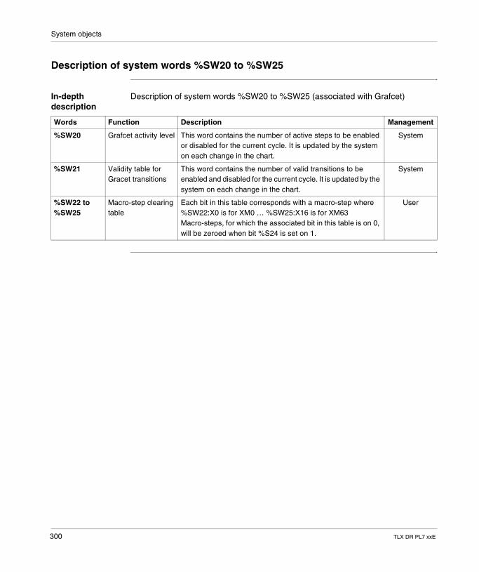
System objects
Description of system words %SW20 to %SW25
In-depth description
Description of system words %SW20 to %SW25 (associated with Grafcet)
Words Function Description Management
%SW20 Grafcet activity level This word contains the number of active steps to be enabled or disabled for the current cycle. It is updated by the system on each change in the chart.
System
%SW21 Validity table for Gracet transitions
This word contains the number of valid transitions to be enabled and disabled for the current cycle. It is updated by the system on each change in the chart.
System
%SW22 to %SW25
Macro-step clearing table
Each bit in this table corresponds with a macro-step where %SW22:X0 is for XM0 … %SW25:X16 is for XM63Macro-steps, for which the associated bit in this table is on 0, will be zeroed when bit %S24 is set on 1.
User
300 TLX DR PL7 xxE

System objects
Description of system words %SW30 to %SW35
In-depth description
Description of system words %SW30 to %SW35
Words Function Description Management
%SW30 Master task execution time
Indicates the execution time of the last master task cycle (in ms).
System
%SW31 Maximum master task execution time
Indicates the longest master task execution time from the last cold start (in ms).
System
%SW32 Minimum master task execution time
Indicates the shortest master task execution time from the last cold start (in ms).
System
%SW33 Fast task execution time
Indicates the execution time of the last fast task cycle (in ms). System
%SW34 Maximum fast task execution time
Indicates the longest fast task execution time from the last cold start (in ms).
System
%SW35 Minimum fast task execution time
Indicates the shortest fast task execution time from the last cold start (in ms).
System
Note: More detail on execution time: this is the time elapsed between the beginning (input acquisition) and the end (output update) of a scanning period. This time includes the processing of event tasks and fast tasks, as well as processing console requests.
TLX DR PL7 xxE 301
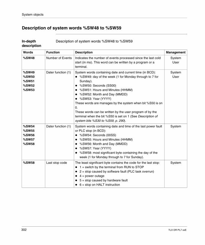
System objects
Description of system words %SW48 to %SW59
In-depth description
Description of system words %SW48 to %SW59
Words Function Description Management
%SW48 Number of Events Indicates the number of events processed since the last cold start (in ms). This word can be written by a program or a terminal.
SystemUser
%SW49%SW50%SW51%SW52%SW53
Dater function (1) System words containing date and current time (in BCD):� %SW49: day of the week (1 for Monday through to 7 for
Sunday).� %SW50: Seconds (SS00)� %SW51: Hours and Minutes (HHMM)� %SW52: Month and Day (MMDD)� %SW53: Year (YYYY)These words are manages by the system when bit %S50 is on 0.These words can be written by the user program of by the terminal when the bit %S50 is set on 1 (See Description of system bits %S30 to %S59, p. 290).
SystemUser
%SW54%SW55%SW56%SW57%SW58
Dater function (1) System words containing date and time of the last power fault or PLC stop (in BCD):� %SW54: Seconds (00SS)� %SW55: Hours and Minutes (HHMM)� %SW56: Month and Day (MMDD)� %SW57: Year (YYYY)� %SW58: most significant byte containing the day of the
week (1 for Monday through to 7 for Sunday).
System
%SW58 Last stop code The least significant byte contains the code for the last stop:� 1 = switch by the terminal from RUN to STOP� 2 = stop caused by software fault (PLC task overrun)� 4 = power outage� 5 = stop caused by hardware fault� 6 = stop on HALT instruction
System
302 TLX DR PL7 xxE
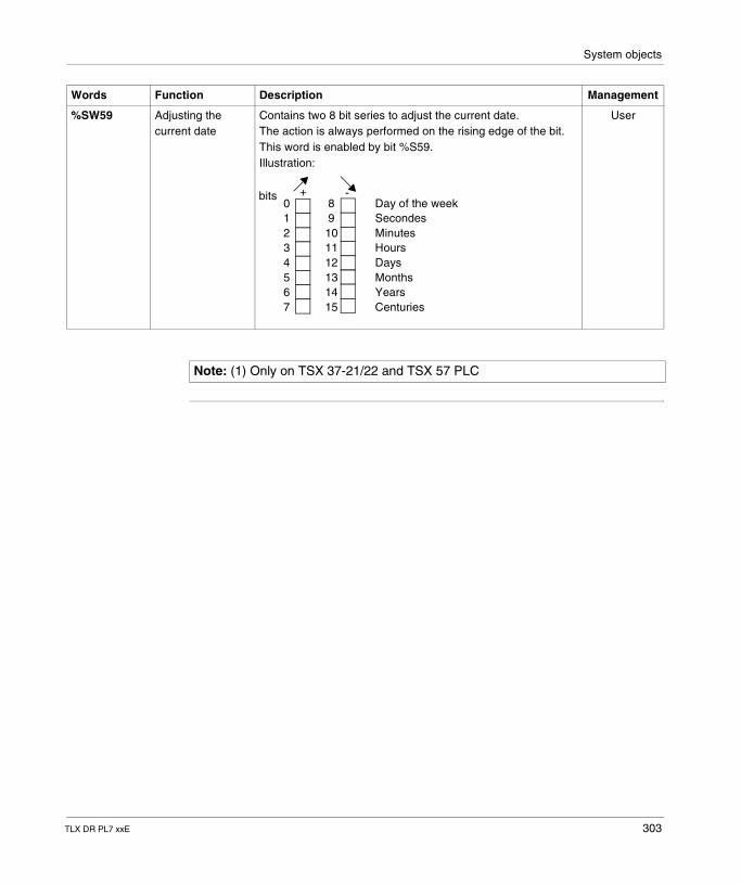
System objects
%SW59 Adjusting the current date
Contains two 8 bit series to adjust the current date.The action is always performed on the rising edge of the bit.This word is enabled by bit %S59.Illustration:
User
Words Function Description Management
01234567
89101112131415
Day of the weekSecondesMinutesHoursDaysMonthsYearsCenturies
+ -bits
Note: (1) Only on TSX 37-21/22 and TSX 57 PLC
TLX DR PL7 xxE 303
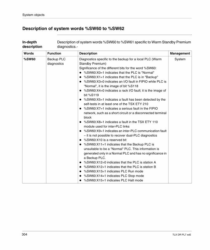
System objects
Description of system words %SW60 to %SW62
In-depth description
Description of system words %SW60 to %SW61 specific to Warm Standby Premium diagnostics.-
Words Function Description Management
%SW60 Backup PLC diagnostics
Diagnostics specific to the backup for a local PLC (Warm Standby Premium)Significance of the different bits for the word %SW60:� %SW60:X0=1 indicates that the PLC is "Normal"� %SW60:X1=1 indicates that the PLC is in "Backup"� %SW60:X3=0 indicates an I/O fault in FIPIO while PLC is
"Normal", it is the image of bit %S118� %SW60:X4=0 indicates a rack I/O fault; it is the image of
bit %S119� %SW60:X5=1 indicates a fault has been detected by the
self-tests in at least one of the TSX ETY 210� %SW60:X7=1 indicates a serious fault in the FIPIO
network, such as a short circuit or a disconnected terminal block
� %SW60:X8=1 indicates a fault in the TSX ETY 110 module used for inter-PLC links
� %SW60:X9=1 indicates an inter-PLC communication fault – it is not possible to recover dual-PLC diagnostics
� %SW60:X10 is a reserved bit� %SW60:X11=1 indicates that the Backup PLC is
unsuitable to be a "Normal" PLC. This information is generated only in a Normal PLC and has no significance in a Backup PLC.
� %SW60:X12=0 indicates that the PLC is station A� %SW60:X12=1 indicates that the PLC is station B� %SW60:X13=1 indicates PLC Run mode� %SW60:X14=1 indicates PLC Stop mode� %SW60:X15=1 indicates PLC Halt mode
System
304 TLX DR PL7 xxE
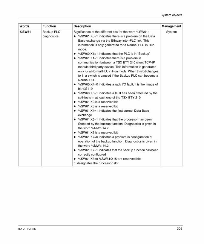
System objects
%SW61 Backup PLC diagnostics
Significance of the different bits for the word %SW61:� %SW61:X0=1 indicates there is a problem on the Data
Base exchange via the Ethway inter-PLC link. This information is only generated for a Normal PLC in Run mode.
� %SW60:X1=1 indicates that the PLC is in "Backup"� %SW61:X1=1 indicates there is a problem in
communication between a TSX ETY 210 client TCP-IP module third party device. This information is generated only for a Normal PLC in Run mode. When this bit changes to 1, a switch is caused if the Backup PLC can become a Normal PLC.
� %SW60:X4=0 indicates a rack I/O fault; it is the image of bit %S119
� %SW60:X5=1 indicates a fault has been detected by the self-tests in at least one of the TSX ETY 210
� %SW61:X2 is a reserved bit� %SW61:X3 is a reserved bit� %SW61:X4=1 indicates the first correct Data Base
exchange� %SW61:X5=1 indicates that the processor has been
Stopped by the backup function. Diagnostics is given in the word %MWp.14.2
� %SW61:X6 is a reserved bit� %SW61:X7=0 indicates a problem in configuration of
operation of the backup function. Diagnostics is given in the word %MWp.14.2
� %SW61:X7=1 indicates that the backup function has been correctly configured
� %SW61:X8 to %SW61:X15 are reserved bitsp: designates the processor slot
System
Words Function Description Management
TLX DR PL7 xxE 305
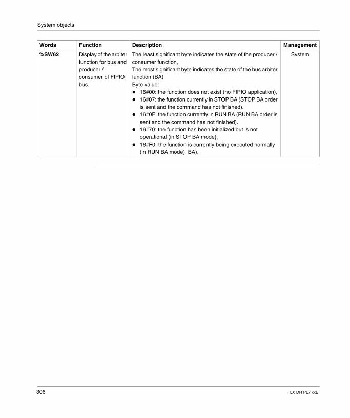
System objects
%SW62 Display of the arbiter function for bus and producer / consumer of FIPIO bus.
The least significant byte indicates the state of the producer / consumer function,The most significant byte indicates the state of the bus arbiter function (BA)Byte value:� 16#00: the function does not exist (no FIPIO application),� 16#07: the function currently in STOP BA (STOP BA order
is sent and the command has not finished).� 16#0F: the function currently in RUN BA (RUN BA order is
sent and the command has not finished).� 16#70: the function has been initialized but is not
operational (in STOP BA mode),� 16#F0: the function is currently being executed normally
(in RUN BA mode). BA),
System
Words Function Description Management
306 TLX DR PL7 xxE
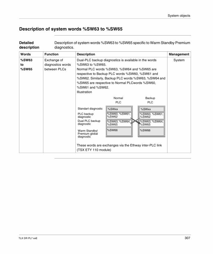
System objects
Description of system words %SW63 to %SW65
Detailed description
Description of system words %SW63 to %SW65 specific to Warm Standby Premium diagnostics.
Words Function Description Management
%SW63to%SW65
Exchange of diagnostics words between PLCs
Dual-PLC backup diagnostics is available in the words %SW63 to %SW65.Normal PLC words %SW63, %SW64 and %SW65 are respective to Backup PLC words %SW60, %SW61 and %SW62. Similarly, Backup PLC words %SW63, %SW64 and %SW65 are respective to Normal PLCwords %SW60, %SW61 and %SW62.Illustration
These words are exchanges via the Ethway inter-PLC link (TSX ETY 110 module)
System
Normal
PLC
Backup
PLC
%SWxx %SWxx
%SW60, %SW61,
Warm StandbylPremium globaldiagnostic
Dual PLC backupdiagnostic
PLC backupdiagnostic
Standart diagnostic
%SW62
%SW63, %SW64,%SW65
%SW66
%SW60, %SW61,%SW62
%SW63, %SW64,%SW65
%SW66
TLX DR PL7 xxE 307
System objects
Description of system words %SW66 to %SW69
Detailed description
Description of system word %SW66 for Warm Standby Premium diagnostics
Words Function Description Management
%SW66 Global diagnostics for Warm Standby Premium architecture
In each of the PLCs, global diagnostics of Warm Standby Premium are created from the backup diagnostics of the two PLCs. These global diagnostics are stored in %SW66. Its bits have the following significance :
System
� %SW66:X0=0 indicates Warm Standby Premium downgraded functioning.� %SW66:X0=1 indicates Warm Standby Premium nominal functioning.� %SW66:X1=1 indicates that PLC A is a Normal PLC� %SW66:21=1 indicates that PLC B is a Normal PLC� %SW66:X3=1 indicates a break-down in inter-PLC communicationInformation on PLC A� %SW66:X4=1 indicates a serious FIPIO network fault on PLC A� %SW66:X5=1 indicates that PLC A is on STOP� %SW66:X6=1 indicates that PLC A is on Halt� %SW66:X7=1 indicates an Ethernet TCP-IP communication breakdown in PLC A (module TSX
ETY 210 or client function)� %SW66:X8=1 indicates a breakdown on at least one of the racked modules in PLC A� %SW66:X9=1 indicates a breakdown on at least one of FIPIO devices in PLC AInformation on PLC B� %SW66:X10=1 indicates a serious FIPIO network fault on PLC B� %SW66:X11=1 indicates that PLC B is on STOP� %SW66:X12=1 indicates that PLC B is on Halt� %SW66:X13=1 indicates an Ethernet TCP-IP communication breakdown in PLC B (module TSX
ETY 210 or client function)� %SW66:X14=1 indicates a breakdown on at least one of the racked modules in PLC B� %SW66:X15=1 indicates a breakdown on at least one of FIPIO devices in PLC B
Note: %SW66 X4 to %SW66 X15 information is not significant if an inter-PLC communication breakdown is present (%SW66 X3 = 1)
308 TLX DR PL7 xxE
System objects
Description of system words %SW67 to %SW69 for Warm Standby Premium diagnostics.
Words Function Description Management
%SW67 Network address and dual-PLC station address
This word contains the network address and the dual-PLC station address, which can be used to set up inter-PLC communication. This word must be displayed in hexadecimal for interpretation in the following manner :
System
%SW68%SW69
Time base used by EF Tempo.
These words contains a time base used by EF Tempo. It is transferred from the Normal PLC to the Backup PLC for updating and synchronisation.
System
MSB LSBnetwork address station address
TLX DR PL7 xxE 309
System objects
Description of system words %SW80 to %SW89
Detailed description
Description of system words %SW80 to %SW89
Words Function Description Management
%SW80%SW81%SW82%SW83%SW84%SW85%SW86
Telegram and message management
� %SW80: No. of messages sent by the system to the terminal port.
� %SW81: No. of messages received by the system from the terminal port.
� %SW82: No. of messages sent by the system to the PCMCIA module.
� %SW83: No. of messages received by the system from the PCMCIA module.
� %SW84: No. of telegrams sent by the system.� %SW85: No. of telegrams received by the system.� %SW86: No. of messages refused by the system.
SystemUser
%SW87%SW88%SW89
Managing communication flows (1)
� %SW87: Number of requests processed by synchronous server per master (MAST) task cycle.
� %SW88: Number of requests processed by asynchronous server per master (MAST) task cycle.
� %SW89: Number of requests processed by server functions (immediately) per master (MAST) task cycle.
System
Note: (1) Only for TSX/PCX/PMX 57 PLC
310 TLX DR PL7 xxE
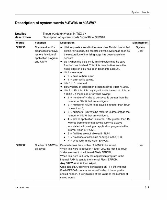
System objects
Description of system words %SW96 to %SW97
Detailed description
These words only exist in TSX 37Description of system words %SW96 to %SW97
Words Function Description Management
%SW96 Command and/or diagnostics for save/restore function of application program and %MW
� bit 0: requests a send to the save zone This bit is enabled on the rising edge. It is reset to 0 by the system as soon as the restoration of the rising edge has been taken into account.
� bit 1: when this bit is on 1, this indicates that the save function has finished. This bit is reset to 0 as soon the rising edge on bit 0 has been taken into account.
� bit 2: save report:� 0 -> save without error,� 1 -> error while saving.
� bits 3 to 5: reserved.� bit 6: validity of application program saves (idem %S96).� bits 8 to 15: this bit is only significant is the report bit is on
1 (bit 2 = 1 means an error while saving):� 1 -> number of %MW to be saved is greater than the
number of %MW that are configured� 2 -> number of %MW to be saved is greater than 1000
or less than 0,� 3 -> number of %MW to be restored is greater than the
number of %MW that are configured� 4 -> size of application in internal RAM greater than 15
Kwords (remember that saving %MW is always associated with saving an application program in the internal Flash EPROM),
� 5 -> facilities are not allowed in RUN,� 6 -> presence of a Backup cartridge in the PLC,� 7 -> write fault in the Flash EPROM.
SystemUser
%SW97 Number of %MW to be saved
Parameterizes the number of %MW to be saved.When this word is between 1 and 1000, the first 1 to 1000 %MW are sent to the internal Flash EPROM.When this word is 0, only the application program in the internal RAM is sent to the internal Flash EPROM.Any %MW save is then wiped.On a cold start, this word is initialized on –1 if the internal Flash EPROM contains no saved %MW. If the opposite should happen, it is initialized at the value of the number of saved words.
User
TLX DR PL7 xxE 311
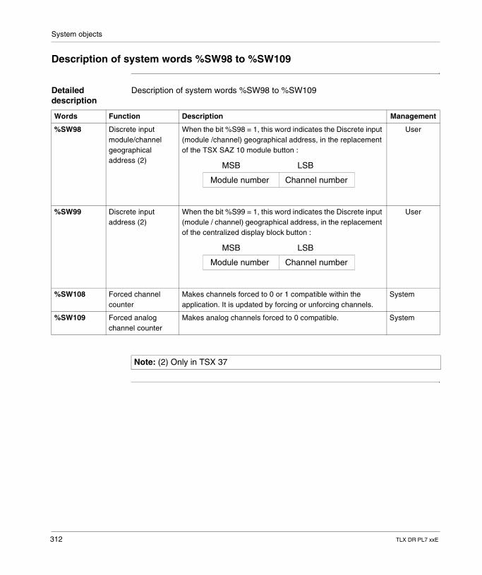
System objects
Description of system words %SW98 to %SW109
Detailed description
Description of system words %SW98 to %SW109
Words Function Description Management
%SW98 Discrete input module/channel geographical address (2)
When the bit %S98 = 1, this word indicates the Discrete input (module /channel) geographical address, in the replacement of the TSX SAZ 10 module button :
User
%SW99 Discrete input address (2)
When the bit %S99 = 1, this word indicates the Discrete input (module / channel) geographical address, in the replacement of the centralized display block button :
User
%SW108 Forced channel counter
Makes channels forced to 0 or 1 compatible within the application. It is updated by forcing or unforcing channels.
System
%SW109 Forced analog channel counter
Makes analog channels forced to 0 compatible. System
Module number Channel number
MSB LSB
Module number Channel number
MSB LSB
Note: (2) Only in TSX 37
312 TLX DR PL7 xxE
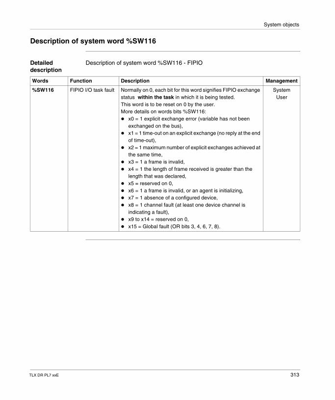
System objects
Description of system word %SW116
Detailed description
Description of system word %SW116 - FIPIO
Words Function Description Management
%SW116 FIPIO I/O task fault Normally on 0, each bit for this word signifies FIPIO exchange status within the task in which it is being tested.This word is to be reset on 0 by the user.More details on words bits %SW116:� x0 = 1 explicit exchange error (variable has not been
exchanged on the bus),� x1 = 1 time-out on an explicit exchange (no reply at the end
of time-out),� x2 = 1 maximum number of explicit exchanges achieved at
the same time,� x3 = 1 a frame is invalid,� x4 = 1 the length of frame received is greater than the
length that was declared,� x5 = reserved on 0,� x6 = 1 a frame is invalid, or an agent is initializing,� x7 = 1 absence of a configured device,� x8 = 1 channel fault (at least one device channel is
indicating a fault),� x9 to x14 = reserved on 0,� x15 = Global fault (OR bits 3, 4, 6, 7, 8).
SystemUser
TLX DR PL7 xxE 313
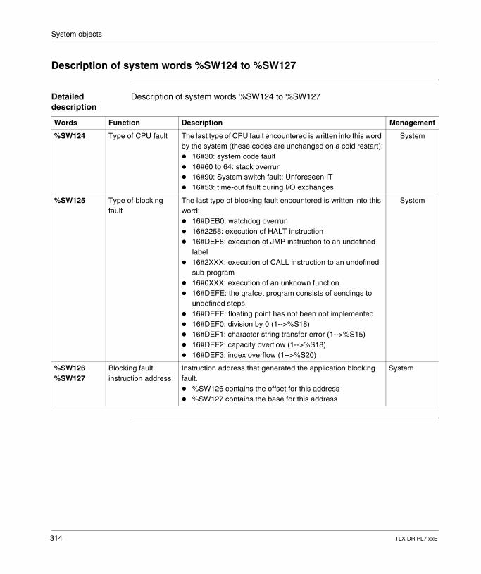
System objects
Description of system words %SW124 to %SW127
Detailed description
Description of system words %SW124 to %SW127
Words Function Description Management
%SW124 Type of CPU fault The last type of CPU fault encountered is written into this word by the system (these codes are unchanged on a cold restart):� 16#30: system code fault� 16#60 to 64: stack overrun� 16#90: System switch fault: Unforeseen IT� 16#53: time-out fault during I/O exchanges
System
%SW125 Type of blocking fault
The last type of blocking fault encountered is written into this word:� 16#DEB0: watchdog overrun� 16#2258: execution of HALT instruction� 16#DEF8: execution of JMP instruction to an undefined
label� 16#2XXX: execution of CALL instruction to an undefined
sub-program� 16#0XXX: execution of an unknown function� 16#DEFE: the grafcet program consists of sendings to
undefined steps.� 16#DEFF: floating point has not been not implemented� 16#DEF0: division by 0 (1-->%S18)� 16#DEF1: character string transfer error (1-->%S15)� 16#DEF2: capacity overflow (1-->%S18)� 16#DEF3: index overflow (1-->%S20)
System
%SW126%SW127
Blocking fault instruction address
Instruction address that generated the application blocking fault.� %SW126 contains the offset for this address� %SW127 contains the base for this address
System
314 TLX DR PL7 xxE
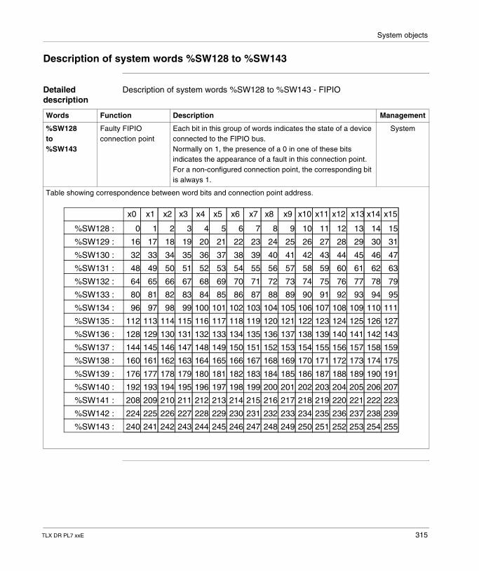
System objects
Description of system words %SW128 to %SW143
Detailed description
Description of system words %SW128 to %SW143 - FIPIO
Words Function Description Management
%SW128to%SW143
Faulty FIPIO connection point
Each bit in this group of words indicates the state of a device connected to the FIPIO bus.Normally on 1, the presence of a 0 in one of these bits indicates the appearance of a fault in this connection point. For a non-configured connection point, the corresponding bit is always 1.
System
Table showing correspondence between word bits and connection point address.
x0 x1 x2 x3 x4 x5 x6 x7 x8 x9 x10 x11 x12 x13 x14 x15
%SW128 :
%SW129 :
%SW130 :
%SW131 :
%SW132 :
%SW133 :
%SW134 :
%SW135 :
%SW136 :
%SW137 :
%SW138 :
%SW139 :
%SW140 :
%SW141 :
%SW142 :
%SW143 :
0 1 2 3 4 5 6 7 8 9 10 11 12 13 14 15
16 17 18 19 20 21 22 23 24 25 26 27 28 29 30 31
32 33 34 35 36 37 38 39 40 41 42 43 44 45 46 47
48 49 50 51 52 53 54 55 56 57 58 59 60 61 62 63
64 65 66 67 68 69 70 71 72 73 74 75 76 77 78 79
80 81 82 83 84 85 86 87 88 89 90 91 92 93 94 95
96 97 98 99 100 101 102 103 104 105 106 107 108 109 110 111
112 113 114 115 116 117 118 119 120 121 122 123 124 125 126 127
128 129 130 131 132 133 134 135 136 137 138 139 140 141 142 143
144 145 146 147 148 149 150 151 152 153 154 155 156 157 158 159
160 161 162 163 164 165 166 167 168 169 170 171 172 173 174 175
176 177 178 179 180 181 182 183 184 185 186 187 188 189 190 191
192 193 194 195 196 197 198 199 200 201 202 203 204 205 206 207
208 209 210 211 212 213 214 215 216 217 218 219 220 221 222 223
224 225 226 227 228 229 230 231 232 233 234 235 236 237 238 239
241 242240 243 244 245 246 247 248 249 250 251 252 253 254 255
TLX DR PL7 xxE 315
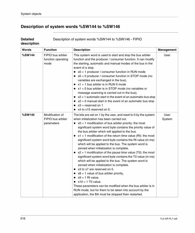
System objects
Description of system words %SW144 to %SW146
Detailed description
Description of system words %SW144 to %SW146 - FIPIO
Words Function Description Management
%SW144 FIPIO bus arbiter function operating mode
This system word is used to start and stop the bus arbiter function and the producer / consumer function. It can modify the starting, automatic and manual modes of the bus in the event of a stop.� x0 = 1 producer / consumer function in RUN mode� x0 = 0 producer / consumer function in STOP mode (no
variables are exchanged in the bus),� x1 = 1 bus arbiter is in RUN 0 mode� x1 = 0 bus arbiter is in STOP mode (no variables or
message scanning is carried out in the bus),� x2 = 1 automatic start in the event of an automatic bus stop� x2 = 0 manual start in the event of an automatic bus stop� x3 = reserved on 1� x4 to x15 reserved on 0.
User
%SW145 Modification of FIPIO bus arbiter parameters
The bits are set on 1 by the user, and reset to 0 by the system when initialization has been carried out.� x0 = 1 modification of bus arbiter priority: the most
significant system word byte contains the priority value of the bus arbiter which will applied to the bus.
� x1 = 1 modification of the return time value (Rt): the most significant system word byte contains the Rt value (in ms) which will be applied to the bus. The system word is zeroed when initialization is complete.
� x2 = 1 modification of the pause time value (T0): the most significant system word byte contains the T0 value (in ms) which will be applied to the bus. The system word is zeroed when initialization is complete.
� x3 to x7 are reserved on 0.� x8 = 1 value of bus arbiter priority,� x9 = 1 Rt value,� x10 = 1 T0 value.These parameters can be modified when the bus arbiter is in RUN mode, but for them to be taken into account by the application, the BA must be stopped then restarted.
UserSystem
316 TLX DR PL7 xxE
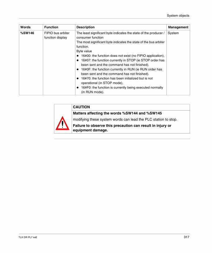
System objects
%SW146 FIPIO bus arbiter function display
The least significant byte indicates the state of the producer / consumer functionThe most significant byte indicates the state of the bus arbiter function.Byte value� 16#00: the function does not exist (no FIPIO application),� 16#07: the function currently in STOP (ie STOP order has
been sent and the command has not finished).� 16#0F: the function currently in RUN (ie RUN order has
been sent and the command has not finished).� 16#70: the function has been initialized but is not
operational (in STOP mode),� 16#F0: the function is currently being executed normally
(in RUN mode).
System
Words Function Description Management
CAUTION
Matters affecting the words %SW144 and %SW145
modifying these system words can lead the PLC station to stop.
Failure to observe this precaution can result in injury or equipment damage.
TLX DR PL7 xxE 317
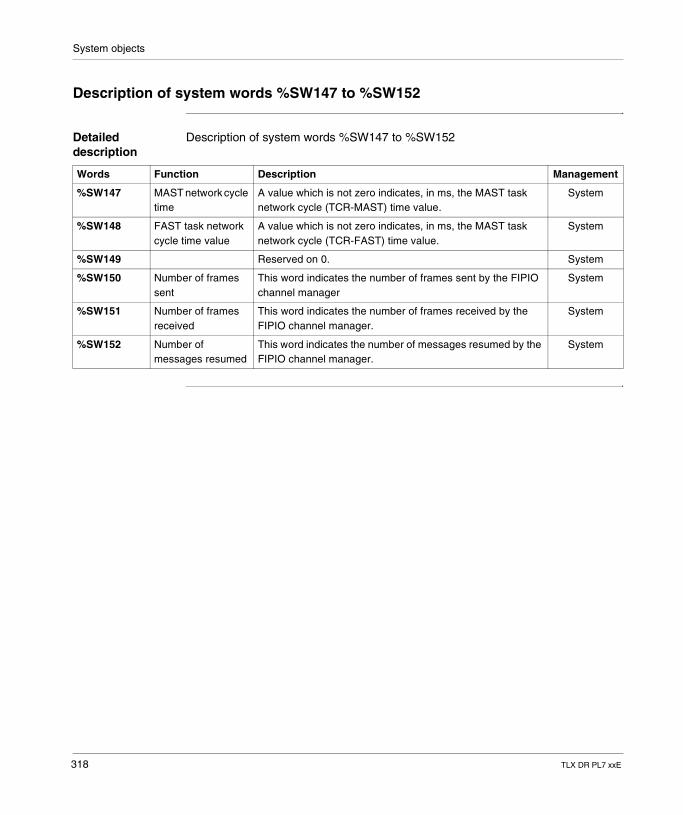
System objects
Description of system words %SW147 to %SW152
Detailed description
Description of system words %SW147 to %SW152
Words Function Description Management
%SW147 MAST network cycle time
A value which is not zero indicates, in ms, the MAST task network cycle (TCR-MAST) time value.
System
%SW148 FAST task network cycle time value
A value which is not zero indicates, in ms, the MAST task network cycle (TCR-FAST) time value.
System
%SW149 Reserved on 0. System
%SW150 Number of frames sent
This word indicates the number of frames sent by the FIPIO channel manager
System
%SW151 Number of frames received
This word indicates the number of frames received by the FIPIO channel manager.
System
%SW152 Number of messages resumed
This word indicates the number of messages resumed by the FIPIO channel manager.
System
318 TLX DR PL7 xxE
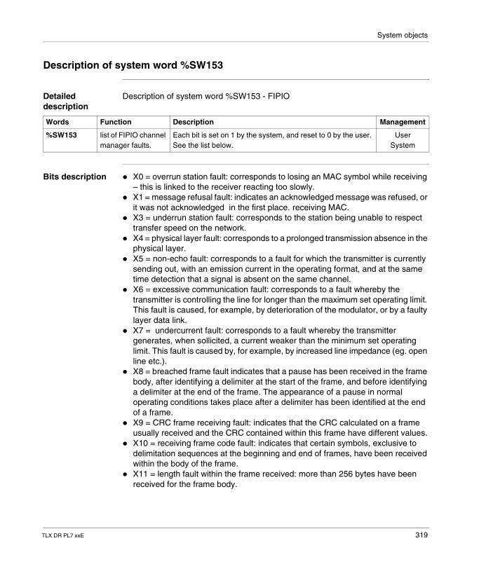
System objects
Description of system word %SW153
Detailed description
Description of system word %SW153 - FIPIO
Bits description � X0 = overrun station fault: corresponds to losing an MAC symbol while receiving – this is linked to the receiver reacting too slowly.
� X1 = message refusal fault: indicates an acknowledged message was refused, or it was not acknowledged in the first place. receiving MAC.
� X3 = underrun station fault: corresponds to the station being unable to respect transfer speed on the network.
� X4 = physical layer fault: corresponds to a prolonged transmission absence in the physical layer.
� X5 = non-echo fault: corresponds to a fault for which the transmitter is currently sending out, with an emission current in the operating format, and at the same time detection that a signal is absent on the same channel.
� X6 = excessive communication fault: corresponds to a fault whereby the transmitter is controlling the line for longer than the maximum set operating limit. This fault is caused, for example, by deterioration of the modulator, or by a faulty layer data link.
� X7 = undercurrent fault: corresponds to a fault whereby the transmitter generates, when sollicited, a current weaker than the minimum set operating limit. This fault is caused by, for example, by increased line impedance (eg. open line etc.).
� X8 = breached frame fault indicates that a pause has been received in the frame body, after identifying a delimiter at the start of the frame, and before identifying a delimiter at the end of the frame. The appearance of a pause in normal operating conditions takes place after a delimiter has been identified at the end of a frame.
� X9 = CRC frame receiving fault: indicates that the CRC calculated on a frame usually received and the CRC contained within this frame have different values.
� X10 = receiving frame code fault: indicates that certain symbols, exclusive to delimitation sequences at the beginning and end of frames, have been received within the body of the frame.
� X11 = length fault within the frame received: more than 256 bytes have been received for the frame body.
Words Function Description Management
%SW153 list of FIPIO channel manager faults.
Each bit is set on 1 by the system, and reset to 0 by the user. See the list below.
UserSystem
TLX DR PL7 xxE 319
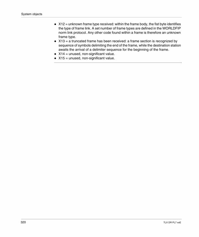
System objects
� X12 = unknown frame type received: within the frame body, the fist byte identifies the type of frame link. A set number of frame types are defined in the WORLDFIP norm link protocol. Any other code found within a frame is therefore an unknown frame type.
� X13 = a truncated frame has been received: a frame section is recognized by sequence of symbols delimiting the end of the frame, while the destination station awaits the arrival of a delimiter sequence for the beginning of the frame.
� X14 = unused, non-significant value.� X15 = unused, non-significant value.
320 TLX DR PL7 xxE
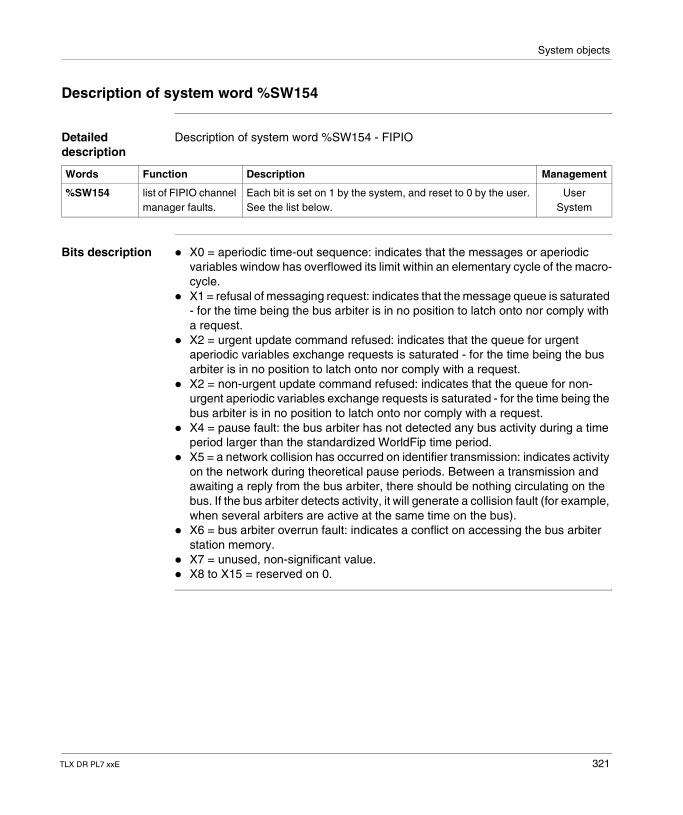
System objects
Description of system word %SW154
Detailed description
Description of system word %SW154 - FIPIO
Bits description � X0 = aperiodic time-out sequence: indicates that the messages or aperiodic variables window has overflowed its limit within an elementary cycle of the macro-cycle.
� X1 = refusal of messaging request: indicates that the message queue is saturated - for the time being the bus arbiter is in no position to latch onto nor comply with a request.
� X2 = urgent update command refused: indicates that the queue for urgent aperiodic variables exchange requests is saturated - for the time being the bus arbiter is in no position to latch onto nor comply with a request.
� X2 = non-urgent update command refused: indicates that the queue for non-urgent aperiodic variables exchange requests is saturated - for the time being the bus arbiter is in no position to latch onto nor comply with a request.
� X4 = pause fault: the bus arbiter has not detected any bus activity during a time period larger than the standardized WorldFip time period.
� X5 = a network collision has occurred on identifier transmission: indicates activity on the network during theoretical pause periods. Between a transmission and awaiting a reply from the bus arbiter, there should be nothing circulating on the bus. If the bus arbiter detects activity, it will generate a collision fault (for example, when several arbiters are active at the same time on the bus).
� X6 = bus arbiter overrun fault: indicates a conflict on accessing the bus arbiter station memory.
� X7 = unused, non-significant value.� X8 to X15 = reserved on 0.
Words Function Description Management
%SW154 list of FIPIO channel manager faults.
Each bit is set on 1 by the system, and reset to 0 by the user. See the list below.
UserSystem
TLX DR PL7 xxE 321
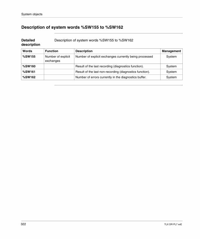
System objects
Description of system words %SW155 to %SW162
Detailed description
Description of system words %SW155 to %SW162
Words Function Description Management
%SW155 Number of explicit exchanges
Number of explicit exchanges currently being processed System
%SW160 Result of the last recording (diagnostics function). System
%SW161 Result of the last non-recording (diagnostics function). System
%SW162 Number of errors currently in the diagnostics buffer. System
322 TLX DR PL7 xxE
CBAIndex
Symbols, 115-, 119, 145%Ci, 41, 43, 45%DRi, 92, 94, 96%MNi, 82, 83, 84%Ri, 86, 88, 89, 90%S0, 284%S1, 284%S10, 285%S100, 295%S101, 295%S102, 295%S11, 285%S118, 295%S119, 295%S13, 285%S15, 285%S16, 286%S17, 287%S18, 287%S19, 287%S20, 288%S21, 289%S22, 289%S23, 289%S24, 289%S26, 289%S30, 290%S31, 290%S38, 290%S39, 290
TLX DR PL7 xx
%S4, 284%S40, 290%S49, 290%S5, 284%S50, 290%S51, 290%S59, 291%S6, 284%S60, 292%S66, 292%S67, 292%S68, 292%S69, 292%S7, 284%S70, 293%S73, 293%S74, 293%S75, 293%S8, 285%S80, 293%S9, 285%S90, 293%S92, 293%S94, 294%S95, 294%S96, 294%S97, 294%S98, 294%S99, 294%SW0, 297%SW1, 297%SW10, 297
323
Index
%SW108, 312%SW109, 312%SW11, 297%SW116, 313%SW12, 299%SW124, 314%SW125, 314%SW126, 314%SW128, 315%SW13, 299%SW144, 316%SW145, 316%SW146, 317%SW147, 318%SW148, 318%SW149, 318%SW150, 318%SW151, 318%SW152, 318%SW153, 319%SW154, 321%SW155, 322%SW160, 322%SW161, 322%SW162, 322%SW17, 299%SW18, 299%SW20, 300%SW21, 300%SW22, 300%SW30, 301%SW31, 301%SW32, 301%SW33, 301%SW34, 301%SW35, 301%SW48, 302%SW49, 302%SW54, 302%SW58, 302%SW59, 303%SW60, 304%SW61, 305%SW62, 306%SW63, 307%SW66, 308
324
%SW67, 309%SW68, 309%SW8, 297%SW80, 310%SW87, 310%SW9, 297%SW96, 311%SW97, 311%SW98, 312%SW99, 312%Ti, 40, 98, 99, 101, 102, 103, 105*, 119, 145+, 119, 145/, 119, 145=, 115>, 115>=, 115
AABS, 119ACOS, 124ADD_DT, 212, 214AND, 22, 147AND_ARX, 234ANDF, 22ANDN, 22ANDR, 22ASIN, 124ATAN, 124
BBCD_TO_INT, 131BIT_D, 236BIT_W, 236
CCOMPARE, 108Compare, 107CONCAT, 182CONCATW, 140COPY_BIT, 233COS, 124
TLX DR PL7 xx
Index
DD_BIT, 238D_TO_INT, 131DATE_TO_STRING, 222, 224DAY_OF_WEEK, 211DBCD_TO_DINT, 131DEG_TO_RAD, 126DELETE, 184DELTA_D, 216DELTA_DT, 218DELTA_TOD, 220DINT_TO_DBCD, 131DINT_TO_REAL, 135DINT_TO_STRING, 173, 176DSHL_RBIT, 241DSHR_RBIT, 241DSHRZ_C, 241
EEND, 73ENDC, 73ENDCN, 73EQUAL, 151EQUAL_ARR, 151EQUAL_STR, 194EXP, 122EXPT, 122
FFIND, 196FIND_, 153FPULSOR, 257FTOF, 253FTON, 251FTP, 255
GGRAY_TO_INT, 138
HHALT, 75
TLX DR PL7 xx
HW, 140
IINSERT, 186Instruction
bit objects, 16INT_TO_BCD, 131INT_TO_DBCD, 131INT_TO_REAL, 135INT_TO_STRING, 173, 176
LLD, 18LDF, 18LDN, 18LDR, 18LEFT, 192LEN, 198LENGTH_, 165LN, 122LOG, 122LW, 140
MMASKEVT, 76MAX_, 156MID, 190MIN_, 156
NNOP, 77NOT, 147NOT_ARX, 234
OObject
Boolean, 17OCCUR_, 158OR, 25, 147OR_ARX, 234
325
Index
ORF, 25ORN, 25ORR, 25
PPL7 Instruction, 14PTC, 210
RR, 20RAD_TO_DEG, 126READ_PCM_EXT, 272READ_PCMCIA, 275REAL_TO_DINT, 135REAL_TO_INT, 135REAL_TO_STRING, 178REM, 145REPLACE, 188RESET, 20RESET_XIT, 278RET, 68RETCN, 68RETURN, 68RIGHT, 192ROL, 109ROL_, 160ROLD, 247ROLW, 247ROR, 109ROR_, 160RORD, 247RORW, 247ROUND, 128RRTC, 207
SS, 20SCHEDULE, 204SCOUNT, 244SET, 20SET_PCM_EXT, 262SET_PCMCIA, 265SHL, 109
326
SHR, 109SIN, 124SORT_, 163SQRT, 119SR, 66ST, 20STN, 20STRING_TO_REAL, 180SUB_DT, 212, 214SUM, 149SUM_ARR, 149System Bits, 282System words, 296
TTAN, 124TIME_TO_STRING, 226TOD_TO_STRING, 228TRANS_TIME, 230TRUNC, 119
UUNMASKEVT, 76
WW_BIT, 238WRITE_PCM_EXT, 267WRITE_PCMCIA, 270WRTC, 208WSHL_RBIT, 241WSHR_RBIT, 241WSHRZ_C, 241
XXOR, 28, 147XOR_ARX, 234XORF, 28XORN, 28XORR, 28
TLX DR PL7 xx