reference manual - omnio
TRANSCRIPT

Intelligent building automation.
Reference ManualOmnio E-Tool

Omnio. Intelligent building automation. 2
Welcome to the world of Omnio
The intelligent radio bus system to control lighting, shading and heating of buildings
If you require more flexibility during building or restoration activities, you should follow new directions starting from scratch. The electric installation specifically challenges archi-tects, planners, electricians and owners. The demand for more comfortable functions wit-hin the building automatically leads to more wiring and requires complicated controls in-cluding complex programming and finally gets very expensive. In consequence of keeping the building budget they skimp on comfort and eco friendliness.
Omnio is a competitive and technical attractive alternative to conventional electric installa-tions. The completely maintenance free system is based on the bidirectional EnOcean radio technology. It connects switches and electric consumers via radio instead of conventional wiring systems. The advantages are obvious.
– Exemplary performance– Highest flexibility during installation– Wide individuality in implementation– Sustainable EnOcean radio technology– Competitive and eco friendly system
Tomorrow’s technology for today’s requirements
Omnio as a part of the electric installation is able to control lighting, shading and heating on an intelligent basis. Omnio relies on the established EnOcean technology, regulated wit-hin the international standard ISO/IEC 14543-3-10.
The systems intelligence is spread out in all actuators and therefore doesn’t need any cen-tral control unit. With it being an open bus system, all Omnio devices can be easily integra-ted and operated by any third-party system.

3 AWAG Elektrotechnik AG, Sandbüelstrasse 2, CH-8604 Volketswil, +41449081919, www.awag.ch
Table of contents
Introduction ..........................................................................................................................................................9License ...............................................................................................................................................................9Installation ......................................................................................................................................................9Workflow ....................................................................................................................................................... 10User level ....................................................................................................................................................... 10
Remote access ................................................................................................................................................... 11Factory mode ............................................................................................................................................... 11Default settings .......................................................................................................................................... 11
Project .................................................................................................................................................................. 12New ................................................................................................................................................................. 12Load ................................................................................................................................................................. 12Save ................................................................................................................................................................. 13Save as ............................................................................................................................................................ 13PDF… ................................................................................................................................................................ 13Project specific Reman code................................................................................................................... 13
Devices ................................................................................................................................................................. 14ReMan Scan .................................................................................................................................................. 14Edit .................................................................................................................................................................. 14Clone ............................................................................................................................................................... 15Combine ........................................................................................................................................................ 15Add device..................................................................................................................................................... 16Delete ............................................................................................................................................................. 16
Edit configuration ............................................................................................................................................ 17Name, Location, Type ................................................................................................................................ 17PDF… ................................................................................................................................................................ 18Replace… ........................................................................................................................................................ 18Edit sender .................................................................................................................................................... 18Add sender.................................................................................................................................................... 19Delete sender ............................................................................................................................................... 20ReMan ............................................................................................................................................................ 20Read back ...................................................................................................................................................... 21Compare ........................................................................................................................................................ 21Read 1 ............................................................................................................................................................. 21Send to save ................................................................................................................................................. 22
EnOcean Remote Management ................................................................................................................. 23Status ............................................................................................................................................................. 23Security code................................................................................................................................................ 24Signal strength ........................................................................................................................................... 24
Filter ...................................................................................................................................................................... 25Macros .................................................................................................................................................................. 26
Example in MS Excel ................................................................................................................................. 27Functions............................................................................................................................................................. 28ARCO-Functions ................................................................................................................................................ 29
Function X01: Gateway ........................................................................................................................... 29Function X03: Rocker splitter ................................................................................................................ 29Function X06: Button splitter................................................................................................................ 30

Omnio. Intelligent building automation. 4
Function X10: Unlock ARCO ................................................................................................................... 30AWAG-Functions .............................................................................................................................................. 31
Function A01: Presence simulation with rocker ............................................................................ 31Function A02: Presence simulation with key-card switch ......................................................... 31Function A04: Presence simulation with rocker, all channels ................................................. 32Function A05: Lock with rocker ............................................................................................................. 32Function A23: Timer EcoSwitch (AW23) ............................................................................................ 33Function A24: Timer TimeSwitch (AW24) ......................................................................................... 33Function A25: Timer ComfortSwitch (AW25) .................................................................................. 34
Dimmer functions ........................................................................................................................................... 35Function D01: Switch off ......................................................................................................................... 35Function D02: Dim with rocker ............................................................................................................ 35Function D03: Dim with button ........................................................................................................... 35Function D04: Predefined dim value .................................................................................................. 36Function D05: Step switch (AW20) ...................................................................................................... 36Function D06: Switch with rocker ....................................................................................................... 37Function D10: Soft dimming ................................................................................................................. 37Function D15: Dimmer-follower .......................................................................................................... 38Function D22: Scene ................................................................................................................................. 38
Gateway functions .......................................................................................................................................... 39Function G01: Filter sender address ................................................................................................... 39Function G02: Filter sender base address ........................................................................................ 39
Blind functions.................................................................................................................................................. 40Function J01: Move with rocker short ................................................................................................ 40Function J02: Move with rocker long ................................................................................................. 40Function J03: Go to position with priority ....................................................................................... 40Function J04: Stop ..................................................................................................................................... 41Function J05: Sequential rocker ........................................................................................................... 41Function J06: Window contact ............................................................................................................. 42Function J07: Go to position with button ........................................................................................ 42Function J08: Temperature control with rocker ............................................................................. 43Function J09: Temperature sensor ...................................................................................................... 43Function J10: Window handle .............................................................................................................. 44Function J11: Weather station .............................................................................................................. 44Function J12: Temperature control with key-card switch .......................................................... 45Function J13: Set alarm state ................................................................................................................ 45Function J14: Go to position with rocker .......................................................................................... 46Function J15: Move/Stepper .................................................................................................................. 46Function J22: Scene ................................................................................................................................... 47
Switching functions ........................................................................................................................................ 48Extension input .......................................................................................................................................... 48Function S01: Switch with rocker ........................................................................................................ 49Function S02: Switch on .......................................................................................................................... 49Function S03: Switch off ......................................................................................................................... 50Function S04: Pulse ................................................................................................................................... 50Function S05: Step switch (AW20) ...................................................................................................... 51Function S06: Sequential push-button ............................................................................................. 52Function S07: Blinking ............................................................................................................................. 53

5 AWAG Elektrotechnik AG, Sandbüelstrasse 2, CH-8604 Volketswil, +41449081919, www.awag.ch
Function S08: Short/long with push-button .................................................................................. 54Function S09: Window contact ............................................................................................................ 54Function S10: Window handle ............................................................................................................. 55Function S11: Central on ......................................................................................................................... 55Function S12: Central off ........................................................................................................................ 55Function S20: Toilet fan ........................................................................................................................... 56Function S21: Toilet fan PIR .................................................................................................................... 57Function S22: Scene .................................................................................................................................. 57
Thermostat functions .................................................................................................................................... 58Logger ............................................................................................................................................................. 58Function H01: Room sensor ................................................................................................................... 59Function H02: Heating Control Panel ................................................................................................ 59Function H03: Setpoint shifting ........................................................................................................... 60Function H04: Window contact ........................................................................................................... 61Function H05: Window handle ............................................................................................................ 61Function H06: Second setpoint ............................................................................................................ 62Function H07: Setpoint switchover with rocker ............................................................................. 62Function H08: Setpoint switchover with key-card switch .......................................................... 63Function H09: Temperature sensor .................................................................................................... 63Function H10: Temperature as setpoint ........................................................................................... 64
Weather station ................................................................................................................................................ 65Device properties ............................................................................................................................................. 66
Action on alarm .......................................................................................................................................... 66Active power* .............................................................................................................................................. 66Active set point* ......................................................................................................................................... 66Automatic end position ........................................................................................................................... 67Automatic suppression timer* ............................................................................................................. 67Azimuth* ....................................................................................................................................................... 67Base ID ........................................................................................................................................................... 67Blinds command (F01) ............................................................................................................................. 68Blinds mode ................................................................................................................................................. 68Blinds position* .......................................................................................................................................... 68Blinds runtime ............................................................................................................................................ 68Blinds sun direction .................................................................................................................................. 69Blinds sun off delay ................................................................................................................................... 69Blinds sun on delay ................................................................................................................................... 69Blinds sun threshold ................................................................................................................................. 70Blinds wind off delay ................................................................................................................................ 70Blinds wind on delay ................................................................................................................................ 70Blinds wind threshold .............................................................................................................................. 70Bridge-Nr. ...................................................................................................................................................... 70Channel disabled ....................................................................................................................................... 71Channels* ...................................................................................................................................................... 71Chip temperature* .................................................................................................................................... 71Clone count .................................................................................................................................................. 71Current monitor* ....................................................................................................................................... 72Current run* ................................................................................................................................................. 72Date* ............................................................................................................................................................... 72

Omnio. Intelligent building automation. 6
Day/night signal transmission ............................................................................................................. 72Day of week* ................................................................................................................................................ 73Daytime* ....................................................................................................................................................... 73Dead time ..................................................................................................................................................... 73Default hysteresis ...................................................................................................................................... 73Default setpoint ......................................................................................................................................... 74Demomode ................................................................................................................................................... 74Device command ....................................................................................................................................... 74Dim timer (EEP)* ......................................................................................................................................... 74Dim value* .................................................................................................................................................... 75EEP ................................................................................................................................................................... 75Elevation* ...................................................................................................................................................... 75Emergency mode* ...................................................................................................................................... 75Energy counter* .......................................................................................................................................... 75Expects ACK .................................................................................................................................................. 76Extension input mode* ............................................................................................................................ 76Extension input telegram type ............................................................................................................. 76Feedback telegram type .......................................................................................................................... 76Feedback trigger ......................................................................................................................................... 77Hysteresis* .................................................................................................................................................... 78If window open ........................................................................................................................................... 78Input evaluation ......................................................................................................................................... 78Input filter mode ........................................................................................................................................ 79Latitude* ........................................................................................................................................................ 79Load* ............................................................................................................................................................... 79Load measurement ................................................................................................................................... 79Load number* .............................................................................................................................................. 80Location ......................................................................................................................................................... 80Lock-out (high-level)* ................................................................................................................................ 80Logged entries* ........................................................................................................................................... 80Logger time range ..................................................................................................................................... 80Longtitude* .................................................................................................................................................. 80Manual programming mode ................................................................................................................ 80Minimum phase angle ............................................................................................................................ 81MINI type ....................................................................................................................................................... 81Motor delay .................................................................................................................................................. 81Name .............................................................................................................................................................. 82Network node number ............................................................................................................................ 82Operating mode* ....................................................................................................................................... 82Output cascade .......................................................................................................................................... 82Output locked* ............................................................................................................................................ 82Output mode ............................................................................................................................................... 83PIR level .......................................................................................................................................................... 83Presence simulation*................................................................................................................................ 83Protocol type (RRT)..................................................................................................................................... 84Radio telegrams received* ...................................................................................................................... 84Radio telegrams transmitted* .............................................................................................................. 84Rain sensor* ................................................................................................................................................. 84

7 AWAG Elektrotechnik AG, Sandbüelstrasse 2, CH-8604 Volketswil, +41449081919, www.awag.ch
REG type ........................................................................................................................................................ 84Relay cycles* ................................................................................................................................................. 85Relay output* ............................................................................................................................................... 85Remote access permissions* .................................................................................................................. 85Remote access settings ............................................................................................................................ 85Remote access timer* ............................................................................................................................... 86Repeater ........................................................................................................................................................ 86Repositioning in* ....................................................................................................................................... 86Runs before repositioning ...................................................................................................................... 87Security code allowed............................................................................................................................... 87Security code set* ....................................................................................................................................... 87Sender address ............................................................................................................................................ 88Sender list size* ........................................................................................................................................... 88Sends ACK ..................................................................................................................................................... 88Sensor alarm transmission .................................................................................................................... 88Setpoint* ....................................................................................................................................................... 88Setpoint 1* .................................................................................................................................................... 89Setpoint 2* .................................................................................................................................................... 89Setpoint range for H01 ............................................................................................................................ 89Setpoint shifting duration* .................................................................................................................... 89Setpoint shifting temperature* ............................................................................................................ 89Shading position ....................................................................................................................................... 90Shading angle ............................................................................................................................................ 90Simulation change in* ............................................................................................................................. 91Simulation on for* ..................................................................................................................................... 91Slats angle* ................................................................................................................................................... 91Slats rotation time ..................................................................................................................................... 91Start-up behaviour .................................................................................................................................... 91Staircase light duration ........................................................................................................................... 92Staircase light prewarning function .................................................................................................. 93Stepper (J15), step duration ................................................................................................................... 93Stepper (J15), pause duration ............................................................................................................... 93Summertime*.............................................................................................................................................. 94Sun west, south, east* .............................................................................................................................. 94Telegram repetitions ................................................................................................................................ 94Temperature* ............................................................................................................................................... 94Temperature control* ............................................................................................................................... 95Temperature evaluation* ........................................................................................................................ 95Temperature monitor* ............................................................................................................................. 95Test blinds ..................................................................................................................................................... 95Test dimmer ................................................................................................................................................. 95Test switching actuator ........................................................................................................................... 95Test thermostat actuator ........................................................................................................................ 96Time* ............................................................................................................................................................... 96TST Hardware............................................................................................................................................... 96Twilight sensor* .......................................................................................................................................... 96Type ................................................................................................................................................................. 96UP hardware ................................................................................................................................................ 97

Omnio. Intelligent building automation. 8
Up time* ........................................................................................................................................................ 97Version*.......................................................................................................................................................... 97Weather data selection............................................................................................................................ 97Weather data transmission ................................................................................................................... 98Weather lock-out* ...................................................................................................................................... 98Weather lock-out delay ............................................................................................................................ 98Weather lock-out delay timer* .............................................................................................................. 98Window open* ............................................................................................................................................ 98Wind speed* ................................................................................................................................................. 99

9 AWAG Elektrotechnik AG, Sandbüelstrasse 2, CH-8604 Volketswil, +41449081919, www.awag.ch
Introduction
With the AWAG software E-Tool all actuators of the Omnio product line can be configured completely by radio without manual access to the device. The software is also used for plan-ning, start-up and troubleshooting on site.
LicenseE-Tool is free of charge, no license is required. It can be downloaded from the AWAG website, see www.awag.ch.
InstallationE-Tool runs on the Windows operating system. It consists of a singele EXE-file and no ins-tallation is required. An Omnio gateway SG-USB300 is needed for proper function of E-Tool. The gateway serves as interface between the computer and EnOcean radio telegrams. It is available form AWAG Elektrotechnik AG, www.awag.ch, Art.-No. 6044 000.
It may be necessary to install a driver for the virtual COM-port. The driver is included in the E-Tool zip file, it is also available from the FTDI-Chip manufacturer website www.ftdichip.com/drivers/vcp.htm.
After program start-up, select the appropriate Omnio USB-interface and the transmission rate (57.6 kBd). When properly configured, all EnOcean radio telegrams appear in the moni-tor window on the right handside.

Omnio. Intelligent building automation. 10
WorkflowWith the E-Tool software, Omnio actuators can be configured via radio without having to manually access the device. The entire configuration can be stored electronically in a project file. The configuration takes place in three steps:
1» Load configurationBefore you can (re-) configure an Omnio actuator, its current configuration needs to be read into E-Tool. This is done in two ways, either by opening the corresponding project file or by reading the actuator directly via radio.
2» Edit configurationThen, the configuration can be edited and adapted in E-Tool as desired.
3» Save configurationFinally, the data needs to be transferred back to the actuator and the project file needs to be saved.
User levelVia the pink program icon in the top left corner one can select the user level in the menu E-Tool Options. Depending on the user level, certain parameters and menu commands are hidden, which makes the program easer at the beginning.
Basic: for beginnersExpert: for advanced usersService: for experts.
Note: If no parameters are visible, the user level is probably too low.
11 AWAG Elektrotechnik AG, Sandbüelstrasse 2, CH-8604 Volketswil, +41449081919, www.awag.ch
Remote access
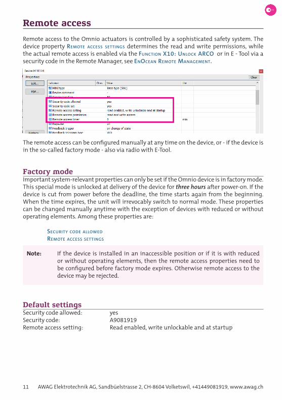
Remote access to the Omnio actuators is controlled by a sophisticated safety system. The device property Remote access settings determines the read and write permissions, while the actual remote access is enabled via the Function X10: unlock aRco or in E - Tool via a security code in the Remote Manager, see enocean Remote management.
The remote access can be configured manually at any time on the device, or - if the device is in the so-called factory mode - also via radio with E-Tool.
Factory modeImportant system-relevant properties can only be set if the Omnio device is in factory mode. This special mode is unlocked at delivery of the device for three hours after power-on. If the device is cut from power before the deadline, the time starts again from the beginning. When the time expires, the unit will irrevocably switch to normal mode. These properties can be changed manually anytime with the exception of devices with reduced or without operating elements. Among these properties are:
secuRity code allowed
Remote access settings
Note: If the device is installed in an inaccessible position or if it is with reduced or without operating elements, then the remote access properties need to be configured before factory mode expires. Otherwise remote access to the device may be rejected.
Default settingsSecurity code allowed: yesSecurity code: A9081919Remote access setting: Read enabled, write unlockable and at startup

Omnio. Intelligent building automation. 12
Project
The project file contains the configuration of Omnio devices in electronic form in CSV for-mat. On the one hand, projects can be created at the desk, on the other hand, the configu-ration of existing units can be documented and changed.
The dialog box is accessed by clicking the Project button.
The project file can also be edited with a text editor or in MS Excel, see also chapter macRos.
Note: If the CSV file is edited incorrectly, E-Tol might not be able to read it. It is the-refore advisable to create a backup copy before making manual changes.
NewCreates a new project and empties the device list at the same time. Under Designations, the project can be given a name, a number and a comment.
Note: The file name is not set until the file is saved.
LoadLoads a project saved in CSV format and displays all devices in the device list.

13 AWAG Elektrotechnik AG, Sandbüelstrasse 2, CH-8604 Volketswil, +41449081919, www.awag.ch
SaveSaves the current project file in CSV format. With Clear, unwanted (i.e. unprocessed) devices that do not originate from a project file will be removed.
Note: For the complete configuration of the Omnio actuators to be contained in the project file, the devices must first be read in individually, see Read back.
Save asSave the project file in CSV format under a new filename. The dialog window must then be closed.
PDF…Create a complete project documentation in PDF format and open the PDF reader to display the document.
Project specific Reman codeIn order to prevent unwanted access by third parties to personal Omnio actuators through the standard password, a password can be set here. It is stored in encrypted form in the project file and displayed in the ReMan dialogue instead of the standard password, see enocean Remote management.
Note: For security reasons it is strongly advised to use an unique password for each project. The password must be set manually for each Omnio actuator, see also secuRity code.

Omnio. Intelligent building automation. 14
Devices
Omnio devices can be added in different ways:
- by loading a project file, see chapter PRoject
- by using the Reman scan command, see below- Omnio device sends a UTE-teach-in telegram, see device command.
ReMan ScanFind all Omnio devices that are within range and display them with the corresponding icon in the device list.
EditTo edit a device, mark it in the device list and select Edit, see also chapter edit conFiguRation.

15 AWAG Elektrotechnik AG, Sandbüelstrasse 2, CH-8604 Volketswil, +41449081919, www.awag.ch
CloneDuplicate an Omnio device from the device list. The cloned device has the same configu-ration as the original device, but it does not yet have a valid EnOcean ID. Usually, a cloned device is combined with an existing device, see combine below.
CombineCombine two devices. The second device is marked with Ctrl - Click. A cloned device is usual-ly used, see clone above. The configuration of the physically present device (valid EnOcean ID) is overwritten with that of the cloned device (invalid EnOcean ID) and the cloned device is deleted. The configuration must then be stored on the device with send to save.
Note: The button Edit... changes to Combine... as soon as the second device has been selected with Ctrl - Click.
Note: Instead of clone/combine, the device command RePlace... can also be used.

Omnio. Intelligent building automation. 16
Add deviceManually add a device to the device list. In the dialog box, a name, location, type and EnO-cean ID can be entered. If the device itself is not yet known but only its ID, the device can still be fully configured.
DeleteDelete an Omnio device from the list.

17 AWAG Elektrotechnik AG, Sandbüelstrasse 2, CH-8604 Volketswil, +41449081919, www.awag.ch
Edit configuration
To configure a device, mark it in the device list and select Edit. The configuration of the device appears in the editing dialog. Depending on whether the device has been manually added, scanned, or opened from a project file, this dialog is almost empty and the configu-ration has to be read by the device itself, see Read back.
The device properties are displayed in the upper table, a detailed description of all device properties can be found in the chapter device PRoPeRties. The programmed transmitters are listed in the lower table, a detailed description can be found in chapter Functions.
Note: Some device properties and most functions are device-specific.
Note: To make the changes effective, they must be saved on the device with the send to save command.
Name, Location, TypeName and location can be chosen freely and they are stored on the actuator. After a Read back command they appear in the device properties name and location. The four additional labels only appear in the project file and can be used for custom identification of the device.
Note: The type is normally recognised automatically, see device property tyPe. It may only be changed manually in exceptional cases, as otherwise the device may behave unpredictably or incorrectly!

Omnio. Intelligent building automation. 18
PDF…Creates a detailed project documentation in PDF format.
Replace...Copy the configuration of another device of the same type to the current device. The origi-nal device can be selected from a list. Security code and base ID are not copied. To save the new configuration on the device, comPaRe and then send to save have to be chosen.
Edit senderEach sender is assigned a function and a number of parameters, which can be changed via Paired senders - Edit. However, not all of the functions and parameters can be changed, e.g. rocker functions, since two buttons are affected (rocker O and I). In this case, you must delete the sender first and then re-program it with the desired function.

19 AWAG Elektrotechnik AG, Sandbüelstrasse 2, CH-8604 Volketswil, +41449081919, www.awag.ch
Add senderAdd a new sender to the sender list. At programming, the sender is assigned a function which can be parameterised.
In the dialog box, you can select the sender on the left side and the desired function on the right side.
Note: In order for the sender to appear in the drop-down list, it must have sent at least one telegram before the dialog call, i.e. if you want to program a rocker, one of its buttons must have been pressed previously.

Omnio. Intelligent building automation. 20
If the transmitter is predefined, all functions matching the transmitter type can be listed with List functions matching the sender. Conversely, if the function is predefined, all mat-ching transmitters can be listed with List senders matching the function.
In the lower part, sender specific parameters can be specified on the left side and function specific parameters on the right side.
Delete senderDelete the marked sender.
Note: Both sides of a rocker have to be deleted separately (AI-AO / BI-BO).
ReManEnOcean Remote Management functions, see chapter enocean Remote management.

21 AWAG Elektrotechnik AG, Sandbüelstrasse 2, CH-8604 Volketswil, +41449081919, www.awag.ch
Read backLoads the configuration of an Omnio device within range. The device properties are display-ed in the upper list, the programmed sender in the lower list.
CompareLoads the configuration of an Omnio device within radio range and compares it with the configuration stored in the project file. The differences are marked yellow.
Read 1The same as the Read back command, but only reads the selected device property and is therefore much faster.

Omnio. Intelligent building automation. 22
Note: This only works with device properties and not with paired senders.
Send to saveSaves the configuration on the actuator. After a successful send command the yellow mar-ked differences disappear.
Note: This function is only allowed with the proper read/write permissions, see also chapter Remote access.

23 AWAG Elektrotechnik AG, Sandbüelstrasse 2, CH-8604 Volketswil, +41449081919, www.awag.ch
EnOcean Remote Management
The EnOcean Remote Management has been fully implemented in all Omnio actuators. It can be accessed via ReMan...
Status
QueryEstablishes a ReMan connection to the Omnio device and displays current information on access rights, security code and radio signal quality.
Note: The first action must always be a query to enable the other buttons.
PingRetrieve the signal strength of the radio signal [dBm] and response time [ms] of the actua-tor. The signal strength is an indicator of the the actuator‘s radio signal quality. The smaller the absolute value of the signal strength, the better is the signal quality, see also signal stRength.
Blink (Action)Both Leds of the Omnio actuator flash five times. This is useful for visual identification of an actuator.

Omnio. Intelligent building automation. 24
Security codeThe remote access can also be enabled by an 8-digit security code. The security code consists of the numbers 0 ... 9 and the characters A ... F (hexadecimal). There’s no difference between upper and lower case.
Note: The default code of Omnio devices is A9081919.
Set…Set 8-digit hexadecimal security code, which sets the device property secuRity code set* to YES. An existing security code will be overwritten without warning. To reset the security code use 00000000. This also sets the device property secuRity code set* to NO.
Note: The security code can only be set if the device property secuRity code allowed is enabled.
Note: To prevent unwanted remote access to the device by third parties, the default security code needs to be changed.
UnlockEnable remote access. The device property Remote access settings determines the read/write permissions for remote access.
LockDisable remote access. The device property Remote access settings determines which read/write permissions are locked.
Signal strengthThe signal strength [dBm] is an indicator of the radio signal’s quality.
-50 dBm Excellent signal quality-60 dBm Good signal quality-85 dBm Poor signal quality-90 dBm Out of range

25 AWAG Elektrotechnik AG, Sandbüelstrasse 2, CH-8604 Volketswil, +41449081919, www.awag.ch
Filter
Configuring devices in an environment with many EnOcean transmitters may become diffi-cult and confusing very quickly. The filter function is very helpful in that case.
The filter can either filter the device window and/or the monitor window. It is possible to have the devices filtered out but display all telegrams.
Telegrams can be filtered by sender address, telegram type and/or signal strength. The de-vices can be selected with arrow keys.
A filter can be saved in a file and loaded on demand. It is saved in XML format, the file type is <file-name>.etf.

Omnio. Intelligent building automation. 26
Macros
Macros are used in the manual processing of project files in CSV format (usually in MS Ex-cel). Macros simplify the configuration of the actuators without E - Tool, as the sensors can be assigned predefined basic functions.
Syntax <->;transmitter slot;ID;function;button;[channel;]
<-> indication of a transmitter slot
; delimiter
Transmitter slot: 1…50
ID EnOcean-ID of transmitter, e.g. ‘002A3512. Important: In Excel, all hex numbers must be preceded by an apostrophe so that they are not mista-kenly converted into another format.
Function Function name
Ann: Awag functions A01 … A25 Dnn: Dimm functions D01 … D22 Gnn: Gateway functions G01 … G02 Jnn: Blind functions J01 … J22 Snn: Switch functions S01 … S22 Xnn: ARCO functions X01 … X10
Button Name of rocker or button. Button D is reserved for window contacts and can’t be programmed. For some sensors (FG, FK, KSM, PIR, RTF) this para-meter can be omitted.
A: rocker A B: rocker B C: rocker C AO: button AO AI: button AI BO: button BO BI: button BI CO: button CO CI: button CI
Channel Actuator channel (optional). If missing, channel 1 is taken by default. This parameter can be omitted for all 1-channel actuators.
CHn: channel 1 … 8 CHA: all channels
27 AWAG Elektrotechnik AG, Sandbüelstrasse 2, CH-8604 Volketswil, +41449081919, www.awag.ch
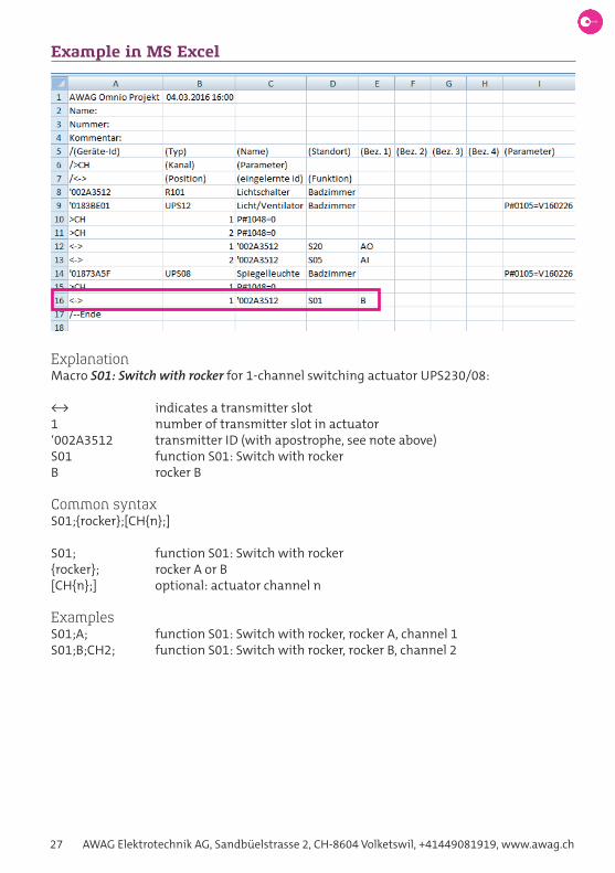
Example in MS Excel
ExplanationMacro S01: Switch with rocker for 1-channel switching actuator UPS230/08:
<-> indicates a transmitter slot1 number of transmitter slot in actuator‘002A3512 transmitter ID (with apostrophe, see note above)S01 function S01: Switch with rockerB rocker B
Common syntaxS01;{rocker};[CH{n};]
S01; function S01: Switch with rocker{rocker}; rocker A or B[CH{n};] optional: actuator channel n
ExamplesS01;A; function S01: Switch with rocker, rocker A, channel 1S01;B;CH2; function S01: Switch with rocker, rocker B, channel 2

Omnio. Intelligent building automation. 28
Functions
Omnio actuators are multifunctional, upto twenty different functions are implemented on each device. At programming, the transmitter is assigned a function on the actuator. Dif-ferent transmitters can have different functions on the same actuator, e.g. transmitter 1 = step switch and transmitter 2 = sequential push button. Each device type familiy provides different functions:
Type DescriptionARCO Xnn: ARCO functions X01 … X10AWAG functions Ann: AWAG functions A01 … A25Dimmer Dnn: Dimmer functions D01 … D22Gateways Gnn: Gateway functions G01 … G02Blind actuators Jnn: Blind functions J01 … J22Switch actuators: Snn: Switch functions S01 … S22Thermostat actuators: Hnn: Thermostat functions H01 … H10
In the following chapters, all functions sorted by device type are described in detail accor-ding to the following scheme:
Description: Function descriptionParameter: Function parameter. The default value is underlined.Lock-outs: Indicates, which lock-outs block the function. This is used
by blind actuators only.Context: Device: Valid for the entire device (i.e. all channels) Channel: Valid for a single channel onlyTransmitter: Type of transmitter the described function can be assig-
ned toDevices: All devices that provide this functionMacros: Syntax of the standard macroMan. configuration: Manual device configuration

29 AWAG Elektrotechnik AG, Sandbüelstrasse 2, CH-8604 Volketswil, +41449081919, www.awag.ch
ARCO-Functions
Function X01: GatewayProgram a gateway in an actuator. The outputs of the actuator can be controlled via the gateway. The communication is based upon VLD-telegrams of the EEP (EnOcean Equipment Profile), see also device property Feedback telegRam tyPe.
Note: Apart from feedback telegrams, 4BS-telegrams to control the actuator are not supported anymore.
Context: DeviceTransmitter: GatewayDevices: KD, KS, KXJ, miniS01, REGH, REGJ, REGS, UPD, UPH, UPJ, UPSMacros: X01;
Manual device configuration0 – LRN (2 s) – 15 Set actuator to programming modeGateway sends UTE Teach-in Actuator receives UTE Teach-in0 – CLR Set actuator to normal mode
Function X03: Rocker splitterThe split function of the button interface sends telegrams of a programmed radio trans-mitter distributed over several channels. Rocker telegrams are sent on the three channels A, B and C of the base ID plus a defined offset. If the length of the keystroke is to be taken into account (max. 8 s), set the parameter Trigger to release (with duration).
Parameter Range Description
Trigger edgeRelease (with duration)
Send time, release takes into account the length of the keypress
ID Offset 1, 2, 3, 4 Sender address = base-ID + offset
Context: DeviceTransmitter: PTM rockerDevices: TSTMacros: X03;{rocker};
Manual device configuration0 – LRN (2 s) – 1 – press rocker 2x – CLR Edge, base-ID + offset 10 – LRN (2 s) – 2 – press rocker 2x – CLR Edge, base-ID + offset 20 – LRN (2 s) – 3 – press rocker 2x – CLR Release, base-ID + offset 30 – LRN (2 s) – 4 – press rocker 2x – CLR Release, base-ID + offset 4

Omnio. Intelligent building automation. 30
Function X06: Button splitterSee also Function X06: button sPlitteR. Button telegrams are sent on the six channels AI, AO, BI, BO, CI and CO of the base ID plus a defined offset. If the length of the keystroke must be considered (max. 8 s), set the parameter Trigger to release (with duration).
Parameter Range Description
Trigger edgeRelease (with duration)
Send time, release takes into account the length of the keypress
ID Offset 5, 6, 7, 8 Sender address = base-ID + offset
Context: DeviceTransmitter: PTM buttonDevices: TSTMacros: X06;{button};
Manual device configuration0 – LRN (2 s) – 5 – press button 2x – CLR Edge, base-ID + offset 50 – LRN (2 s) – 6 – press button 2x – CLR Edge, base-ID + offset 60 – LRN (2 s) – 7 – press button 2x – CLR Release, base-ID + offset 70 – LRN (2 s) – 8 – press button 2x – CLR Release, base-ID + offset 8
Function X10: Unlock ARCOEnable or disable remote access via ARCO (AWAG Remote Commissioning for Omnio) to the actuator with a rocker. The device property Remote access settings determines the read and write permissions for remote access.
Note: This function can only be configured in factory mode via E-Tool or otherwise manually on the actuator itself.
Parameter Range Description
ARCO unlock, lock Action on button I
Context: DeviceTransmitter: PTM rockerDevices: KD, KS, KXJ, miniS01, REGH, REGJ, REGS, TST, UPD, UPH, UPJ, UPSMacros: X10;{rocker};
Manual device configuration2 – LRN (2 s) – 3 – press rocker 2x – CLR Unlock ARCO 7 – LRN (2 s) – 7 – press rocker 2x – CLR Swap buttons O and I

31 AWAG Elektrotechnik AG, Sandbüelstrasse 2, CH-8604 Volketswil, +41449081919, www.awag.ch
AWAG-Functions
Function A01: Presence simulation with rockerUse a rocker to switch the presence simulation on or off. When switched on, the light swit-ches on for 6 … 30 seconds for acknowledgement before the simulation starts. The light then switches on and off at random, also the dimming value is selected randomly. When switched off, the light switches on for 3 seconds and then off for acknowledgement. The presence simulation is automatically switched off as soon as another command is execu-ted. The device properties PResence simulation*, simulation on FoR* and simulation change in* reflect the actual state of the presence simulation.
Parameter Range Description
Channel 1 … n Actuator channel
Action start, stop Action on button I
Context: ChannelTransmitter: PTM rockerDevices: KD, KS, miniS01, REGS, UPD, UPSMacros: A01;{rocker};[CH{n};]
Manual device configuration2 – LRN (2 s) – 0 – press rocker 2x – CLR Presence simulation with rocker
Function A02: Presence simulation with key-card switchUse a key-card switch to switch the presence simulation on or off. When the card is remo-ved, the light switches on for 6 … 30 seconds for acknowledgement before the simulation starts. The light then switches on and off at random, also the dimming value is selected randomly. When the card is inserted, the light switches on for 3 seconds and then off for acknowledgement. The presence simulation is automatically switched off as soon as anot-her command is executed. The device properties PResence simulation*, simulation on FoR* and simulation change in* reflect the actual state of the presence simulation.
Parameter Range Description
Channel 1 … n Actuator channel
Context: ChannelTransmitter: KSM Key-Card SwitchDevices: KD, KS, miniS01, REGS, UPD, UPSMacros: A02;[CH{n};]
Manual device configuration2 – LRN (2 s) – 1 – insert card 2x – CLR Presence sim. with key-card switch
Omnio. Intelligent building automation. 32
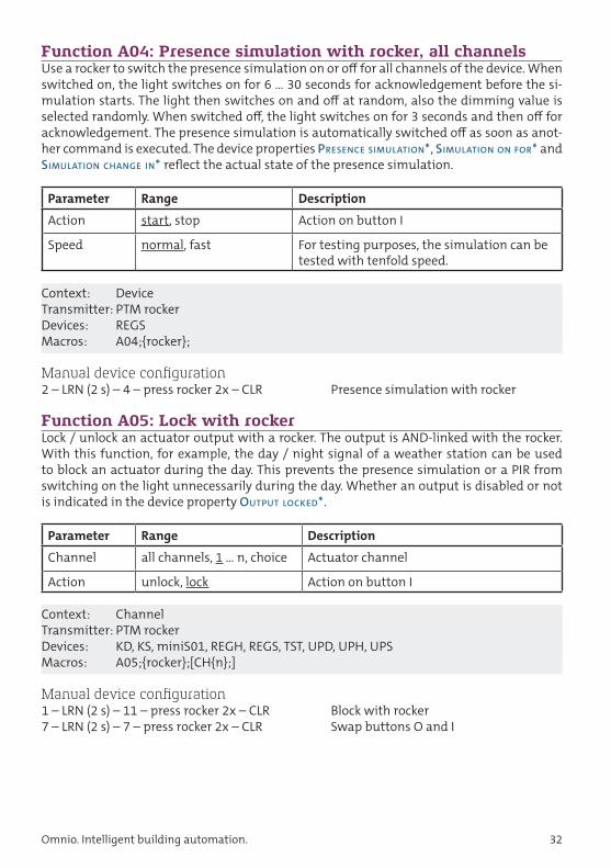
Function A04: Presence simulation with rocker, all channels Use a rocker to switch the presence simulation on or off for all channels of the device. When switched on, the light switches on for 6 … 30 seconds for acknowledgement before the si-mulation starts. The light then switches on and off at random, also the dimming value is selected randomly. When switched off, the light switches on for 3 seconds and then off for acknowledgement. The presence simulation is automatically switched off as soon as anot-her command is executed. The device properties PResence simulation*, simulation on FoR* and simulation change in* reflect the actual state of the presence simulation.
Parameter Range Description
Action start, stop Action on button I
Speed normal, fast For testing purposes, the simulation can be tested with tenfold speed.
Context: DeviceTransmitter: PTM rockerDevices: REGSMacros: A04;{rocker};
Manual device configuration2 – LRN (2 s) – 4 – press rocker 2x – CLR Presence simulation with rocker
Function A05: Lock with rockerLock / unlock an actuator output with a rocker. The output is AND-linked with the rocker. With this function, for example, the day / night signal of a weather station can be used to block an actuator during the day. This prevents the presence simulation or a PIR from switching on the light unnecessarily during the day. Whether an output is disabled or not is indicated in the device property outPut locked*.
Parameter Range Description
Channel all channels, 1 … n, choice Actuator channel
Action unlock, lock Action on button I
Context: ChannelTransmitter: PTM rockerDevices: KD, KS, miniS01, REGH, REGS, TST, UPD, UPH, UPSMacros: A05;{rocker};[CH{n};]
Manual device configuration1 – LRN (2 s) – 11 – press rocker 2x – CLR Block with rocker7 – LRN (2 s) – 7 – press rocker 2x – CLR Swap buttons O and I

33 AWAG Elektrotechnik AG, Sandbüelstrasse 2, CH-8604 Volketswil, +41449081919, www.awag.ch
Function A23: Timer EcoSwitch (AW23)Step switch with staircase light function. With each keystroke the output changes from 0 % to 100 % or vice versa. In addition, the staircase light function is activated, which switches off the light after a set time. The duration is set in the device property staiRcase light duRa-tion. Additionally, a prewarning function can be enabled, see device property staiRcase light PRewaRning Function.
Parameter Range Description
Channel 1 … n Actuator channel
Context: ChannelTransmitter: PTM buttonDevices: KD, KS, miniS01, REGS, UPD, UPSMacros: A23;{button};[CH{n};]
Manual device configuration1 – LRN (2 s) – 7 – press button 2x – CLR Dimmer: Timer EcoSwitch (AW23)0 – LRN (2 s) – 8 – press button 2x – CLR Switch actuators: Timer EcoSwitch (AW23)
Timer duration see staiRcase light duRation
Prewarning function see staiRcase light PRewaRning Function
Function A24: Timer TimeSwitch (AW24)Retriggerable staircase light function. With each keystroke the staircase light function is activated, which switches off the light after a set time. A subsequent keystroke during the time delay retriggers the function. The duration is set in the device property staiRcase light duRation. Additionally, a prewarning function can be enabled, see device property staiRcase light PRewaRning Function.
Parameter Range Description
Channel 1 … n, choice Actuator channel
Context: ChannelTransmitter: PTM button, PIR (EEP: A5-07-03)Devices: KD, KS, miniS01, REGS, UPD, UPSMacros: A24;{button};[CH{n};] (button) A24;[CH{n};] (PIR)
Manual device configuration1 – LRN (2 s) – 8 – press button 2x – CLR Dimmer: Timer TimeSwitch (AW24)1 – LRN (2 s) – 8 – LRN-button PIR – CLR Dimmer (PIR): Timer TimeSwitch0 – LRN (2 s) – 9 – press button 2x – CLR Switch actuators: Timer TimeSwitch (AW24)0 – LRN (2 s) – 9 – LRN-button PIR – CLR Switch actuators (PIR): Timer TimeSwitch
Timer duration see staiRcase light duRation
Prewarning function see staiRcase light PRewaRning Function

Omnio. Intelligent building automation. 34
Function A25: Timer ComfortSwitch (AW25)Retriggerable staircase light function with simple and fourfold time delay. A short keys-troke activates the staircase light function, which switches off the light after a set time. A long keystroke activates the staircase light function with fourfold time delay. A subsequent keystroke during the time delay retriggers the function. The duration is set in the device property staiRcase light duRation. Additionally, a prewarning function can be enabled, see device property staiRcase light PRewaRning Function.
Parameter Range Description
Channel 1 … n Actuator channel
Context: ChannelTransmitter: PTM buttonDevices: KD, KS, REGS, UPD, UPSMacros: A25;{button};[CH{n};]
Manual device configuration1 – LRN (2 s) – 9 – press button 2x – CLR Timer ComfortSwitch (AW25)
Timer duration see staiRcase light duRation
Prewarning function see staiRcase light PRewaRning Function

35 AWAG Elektrotechnik AG, Sandbüelstrasse 2, CH-8604 Volketswil, +41449081919, www.awag.ch
Dimmer functions
Function D01: Switch offSwitch off (0 %) without fading time.
Context: ChannelTransmitter: PTM buttonDevices: KD, UPDMacros: D01;{button};
Manual device configuration0 – LRN (2 s) – 3 – press button 2x – CLR Switch off
Function D02: Dim with rockerDim up or down with a rocker. A short keystroke on button O switches off the dimmer, a long keystroke dims down. A short keystroke on button I switches the dimmer on to the last dimming value, a long keystroke dims up, while a double click turns the dimmer on 100 %.
Parameter Range Description
Direction bright, dark Action on button I
Context: ChannelTransmitter: PTM rockerDevices: KD, UPDMacros: D02;{rocker};
Manual device configuration0 – LRN (2 s) – 0 – press rocker 2x – CLR Dim with rocker (O=off / I=on)0 – LRN (2 s) – 1 – press rocker 2x – CLR Dim with rocker (O=on / I=off)7 – LRN (2 s) – 7 – press rocker 2x – CLR Swap buttons O and I
Function D03: Dim with buttonPush operation of the dimmer. A short keystroke switches the dimmer off or on to the last dim value, a long keystroke dims down or up. Every keystroke is changing the dim direction. A double click turns the dimmer on 100%. The staircase light function can be switched on as well. The duration is set in the device property staiRcase light duRation. Additionally, a pre-warning function can be enabled, see device property staiRcase light PRewaRning Function.
Parameter Range Description
Staircase light function off, on Staircase light function off / on
Context: ChannelTransmitter: PTM buttonDevices: KD, UPDMacros: D03;{button};

Omnio. Intelligent building automation. 36
Manual device configuration0 – LRN (2 s) – 4 – press button 2x – CLR Dim with button1 – LRN (2 s) – 6 – press button 2x – CLR Dim with button, staircase light fct. on
Timer duration see staiRcase light duRation
Prewarning function see staiRcase light PRewaRning Function
Function D04: Predefined dim valueDim to a predefined value with an adjustable fade time via a push-button.
Parameter Range Description
Dim value 0 … 100 % 0 % = off, 100 % = on
Fade time 0, 1 … 7 s Fade time
Context: ChannelTransmitter: PTM button, PIR (EEP: A5-07-01/02/03 und A5-08-01/02/03)Devices: KD, UPDMacros: D04;{button}; (button) D04; (PIR)
Manual device configuration0 – LRN (2 s) – 2 – press button 2x – CLR Dim to 100 % in 0 seconds0 – LRN (2 s) – 6 – press button 2x – CLR Dim to 0 % in 1 seconds0 – LRN (2 s) – 7 – press button 2x – CLR Dim to 15 % in 1 seconds0 – LRN (2 s) – 8 – press button 2x – CLR Dim to 30 % in 1 seconds0 – LRN (2 s) – 9 – press button 2x – CLR Dim to 45 % in 1 seconds0 – LRN (2 s) – 10 – press button 2x – CLR Dim to 60 % in 1 seconds0 – LRN (2 s) – 11 – press button 2x – CLR Dim to 75 % in 1 seconds0 – LRN (2 s) – 12 – press button 2x – CLR Dim to 90 % in 1 seconds0 – LRN (2 s) – 13 – press button 2x – CLR Dim to 100 % in 1 seconds
Fade timeThe second switch position corresponds to the fade time in seconds8 – LRN (2 s) – [0 … 7] – press button 2x – CLR Fade time 0 … 7 s
Function D05: Step switch (AW20)Step switch with fade time. Each keystroke dims from 0 % to 100 % with adjustable fade time from 0 … 7 s, or vice versa.
Parameter Range Description
Fade time 0 … 7 s Fade time
Context: ChannelTransmitter: PTM buttonDevices: KD, UPDMacros: D05;{button};

37 AWAG Elektrotechnik AG, Sandbüelstrasse 2, CH-8604 Volketswil, +41449081919, www.awag.ch
Manual device configuration0 – LRN (2 s) – 5 – press button 2x – CLR Step switch (AW20)The fade time can’t be set manually.
Function D06: Switch with rockerSwitch on and off with a rocker. Pressing the rocker button O switches the dimmer off (0 %), pressing the rocker button I switches the dimmer on to 100 %. Dimming is not possible with this function, it is intended for non-dimmable LED lamps. Since the dimmer switches in the zero-crossing, the inrush currents are virtually eliminated.
Parameter Range Description
Output on, off Action on button I
Context: ChannelTransmitter: PTM rockerDevices: KD, UPDMacros: D06;{rocker};
Manual device configuration0 – LRN (2 s) – 14 – press rocker 2x – CLR Switch with rocker (O = off / I = on)7 – LRN (2 s) – 7 – press rocker 2x – CLR Swap buttons O and I
Function D10: Soft dimmingDim slowly from 0 … 100 % via a push-button, or vice versa. There are two fixed fade times available: soft = 2 minutes and ultrasoft = 15 minutes. The fade times refer to the full dim-ming range from 0 … 100 %. When starting from a different value, they are reduced accor-dingly.
Parameter Range Description
Mode soft onultrasoft onsoft offultrasoft off
Dim direction and fade timesoft = 2 minutesultrasoft = 15 minutes
Context: ChannelTransmitter: PTM button, PIR (EEP: A5-07-01/02/03 und A5-08-01/02/03)Devices: KD, UPDMacros: D10;{button}; (button) D10; (PIR)
Manual device configuration1 – LRN (2 s) – 2 – press button 2x – CLR Dim soft from 0 … 100 %1 – LRN (2 s) – 3 – press button 2x – CLR Dim ultrasoft from 0 … 100 %1 – LRN (2 s) – 4 – press button 2x – CLR Dim soft from 100 … 0 %1 – LRN (2 s) – 5 – press button 2x – CLR Dim ultrasoft from 100 … 0 %

Omnio. Intelligent building automation. 38
Function D15: Dimmer-followerDim synchronized to a master dimmer. This function is used to dimming several lamps at different dimmers synchronously. The master dimmer must send VLD feedback messages (EEP D2-01-03). Since a dimmer follower listens to the feedback signals from the master, visible delays can occur during the dimming process.
Context: ChannelTransmitter: UPD (EEP D2-01-03)Devices: KD, UPDMacros: D15;
Manual device configuration1 – LRN (2 s) – 2x EEP D2-01-03 – CLR Dimmer-follower
Master15 – LRN (2 s) – 6 – press LRN Feedback on change of state15 – LRN (2 s) – 12 – press LRN Telegram type VLD13 – LRN (2 s) – 13 – LRN (2 s) Send 2 VLD telegrams (EEP D2-01-03)
Function D22: SceneProgrammable scene button to store and retrieve the dimming value. A very long keystroke (> 3.5 s) saves the current dim value. The dimmer acknowledges this with a short flicke-ring. A short keystroke restores the saved value with an adjustable fade time from 0 … 120 seconds. The fade time upon manual configuration is fixed at 9 s.
Parameter Range Description
Dim value 0 … 76 % … 100 % 0 % = off, 100 % = on
Fade time 0 … 9 s, 10 s, 15 s, 20 s, 30 s, 1 min, 2 min
Fade time
Context: ChannelTransmitter: PTM buttonDevices: KD, UPDMacros: SZENE; Assign all four PTM buttons as scene buttons D22;{button}; Scene button
Manual device configuration2 – LRN (2 s) – 2 – press button 2x – CLR Scene

39 AWAG Elektrotechnik AG, Sandbüelstrasse 2, CH-8604 Volketswil, +41449081919, www.awag.ch
Gateway functions
Function G01: Filter sender addressProgram EnOcean device in gateway. The address of the device (EnOcean ID) is stored in the gateway’s input filter. When the input filter is activated, the gateway only forwards tele-grams of programmed devices.
Context: DeviceTransmitter: EnOcean DeviceeDevices: APG03B-RSxxx, USB300 (read only)Macros: G01;
Manual device configurationPress S3 on gateway Enable programming modePress LRN-button on EnOcean device Program device into gatewayPress S3 on gateway Enable default mode
Function G02: Filter sender base addressProgram Base-ID of an EnOcean device in gateway. The Base-ID of the device is stored in the gateway’s input filter. When the input filter is activated, the gateway only forwards tele-grams of devices, which are in the address range of the Base-ID. The range is always 128, e.g.:
Base-ID 0xFF801200Range 0xFF801200 … 0xFF80127F
This function is used in conjunction with the Omnio E-Bridge, when telegrams (e.g. central commands) need to be transported across two gateways. Gateway 1 is then programmed with the function G02 in Gateway 2, where Gateway 2 forwards all telegrams from Gate-way 1.
Context: DeviceTransmitter: APG03B-RSxxx, USB300, EnOcean GatewayDevices: APG03B-RSxxxMacros: G02;
Manual device configurationNot possible.

Omnio. Intelligent building automation. 40
Blind functions
Function J01: Move with rocker shortControl the blind via a rocker switch. Button O = move up, button I = move down. If the but-ton is pressed longer than 1 second, the blind moves to the end. If during the movement the button is pressed less than 0.8 seconds, the blind stops. When the blind is at a standstill, the slats are adjusted by briefly pressing the button.
Parameter Range Description
Channel 1 … n, all channels, choice Actuator channel
Direction down, up Action on button I
Lock-outs: Higher-level alarm, window lock-out, weather lock-outContext: ChannelTransmitter: PTM rockerDevices: KXJ, REGJ, UPJMacros: J01;{rocker};[CH{n};]
Manual device configuration0 – LRN (2 s) – 0 – press rocker 2x – CLR Move with rocker short7 – LRN (2 s) – 7 – press rocker 2x – CLR Swap buttons O and I
Function J02: Move with rocker longControl the blind via a rocker switch. Button O = move up, button I = move down. If the but-ton is pressed less than 0.8 seconds, the blind moves to the end. If during the movement the button is pressed longer than 1 second, the blind stops. When the blind is at a standstill, the slats are adjusted by pressing the button longer than 1 second.
Parameter Range Description
Channel 1 … n, all channels, choice Actuator channel
Direction down, up Action on button I
Lock-outs: Higher-level alarm, window lock-out, weather lock-outContext: ChannelTransmitter: PTM rockerDevices: KXJ, REGJ, UPJMacros: J02;{rocker};[CH{n};]
Manual device configuration0 – LRN (2 s) – 1 – press rocker 2x – CLR Move with rocker long7 – LRN (2 s) – 7 – press rocker 2x – CLR Swap buttons O and I
Function J03: Go to position with priorityThe blind moves to an end position when a button is pressed, even if a monitored window is open or the wind alarm is present.

41 AWAG Elektrotechnik AG, Sandbüelstrasse 2, CH-8604 Volketswil, +41449081919, www.awag.ch
Parameter Range Description
Channel 1 … n, all channels, choice Actuator channel
Destination lower end position,upper end position
End position of the blind
Lock-outs: Higher-level alarmContext: ChannelTransmitter: PTM buttonDevices: KXJ, REGJ, UPJMacros: J03;{button};[CH{n};]
Manual device configuration0 – LRN (2 s) – 2 – press button 2x – CLR Go to upper end position with priority0 – LRN (2 s) – 3 – press button 2x – CLR Go to lower end position with priority
Function J04: StopThe blind stops when a button is pressed.
Parameter Range Description
Channel 1 … n, all channels, choice Actuator channel
Context: ChannelTransmitter: PTM buttonDevices: KXJ, REGJ, UPJMacros: J04;{button};[CH{n};]
Manual device configuration0 – LRN (2 s) – 4 – press button 2x – CLR Stop blind
Function J05: Sequential rockerThe blind moves as long as a rocker button is pressed. Button O = go up, button I = go down.
Parameter Range Description
Channel 1 … n, all channels, choice Actuator channel
Direction down, up Action on button I
Lock-outs: Higher-level alarm, window lock-out, weather lock-out Context: ChannelTransmitter: PTM rockerDevices: KXJ, REGJ, UPJMacros: J05;{rocker};[CH{n};]
Manual device configuration0 – LRN (2 s) – 5 – press rocker 2x – CLR Sequential rocker

Omnio. Intelligent building automation. 42
Function J06: Window contactControl the blind via a window contact. If the monitored window opens, the window lock-out is activated and the blind can’t be operated manually anymore. The device property iF window oPen determines, whether the blind goes to the upper end position in that case. The window lock-out is on as long as the window is open. Programmed window contacts and window handles are logical AND-linked.
Window contacts send a heartbeat signal every 15 minutes. After one hour without heart-beat signal the state window open is assumed and the window lock-out will be activated.
Note: Defective window contacts must be deprogrammed, otherwise they block the blinds.
Parameter Range Description
Channel 1 … n Actuator channel
Lock-outs: Higher-level alarm Context: ChannelTransmitter: STM window contact (EEP: D5-00-01)Devices: KXJ, REGJ, UPJMacros: J06;[CH{n};]
Manual device configuration0 – LRN (2 s) – 6 – press LRN on window c. – CLR Window contact13 – LRN (2 s) – 14 – press LRN Deprogram dead window contacts
Function J07: Go to position with buttonMove the blind to a predefined position via a push-button. The end position of the three shading positions can be configured via the corresponding device properties shading Posi-tion and shading angle.
Parameter Range Description
Channel 1 … n, all channels, choice Actuator channel
Destination upper end position,shading position 1 … 3,lower end position
End position of the blind
Lock-outs: Higher-level alarm, window lock-out, weather lock-out Context: ChannelTransmitter: PTM buttonDevices: KXJ, REGJ, UPJMacros: J07;{button};[CH{n};]
Manual device configuration0 – LRN (2 s) – 9 – press button 2x – CLR Upper end position0 – LRN (2 s) – 10 – press button 2x – CLR Shading position 10 – LRN (2 s) – 11 – press button 2x – CLR Shading position 2

43 AWAG Elektrotechnik AG, Sandbüelstrasse 2, CH-8604 Volketswil, +41449081919, www.awag.ch
0 – LRN (2 s) – 12 – press button 2x – CLR Shading position 30 – LRN (2 s) – 13 – press button 2x – CLR Lower end position
Function J08: Temperature control with rockerSwitch the automatic temperature control on and off with a rocker. Button O enables auto-matic temperature control, button I enables manual mode. This function is always used in conjunction with a temperature sensor, see also Function j09: temPeRatuRe sensoR. The device property temPeRatuRe contRol* indicates the operating mode.
Parameter Range Description
Channel 1 … n, all channels, choice Actuator channel
Operation mode manual, automatic Action on button I
Context: ChannelTransmitter: PTM rockerDevices: KXJ, REGJ, UPJMacros: J08;{rocker};[CH{n};]
Manual device configuration0 – LRN (2 s) – 14 – press rocker 2x – CLR Temperature control with rocker
Function J09: Temperature sensorRoom sensor for the temperature controlled automatic function. If the temperature is too high (e.g. sunlight into the room), the blind will go down. The end position is determined with the device property automatic end Position. If it gets too cold in the room (e.g. clouds), the blind will go up. Only one room sensor can be programmed per channel.
The temperature control function can be switched on or off with Function j08: temPeRatuRe contRol with RockeR and Function j11: weatheR station. If none of the two functions is pro-grammed, the operation mode is set to automatic by default.
The temperature setpoint is set at the room sensor itself, from where it is sent to the blind actuator. The range is 0 … 40.8 °C. The hysteresis is permanently set to 2 K, see also device property hysteResis*. After every event the temperature control function is locked for three minutes, see also device property automatic suPPRession timeR*.
If the position of the blind is adjusted manually or via a gateway in automatic mode, it re-mains unchanged for half an hour, after which the automatic mode becomes active again.
Parameter Range Description
Channel 1 … n, all channels, choice Actuator channel
EEP A5-10-10, / -05 / -03 EnOcean Equipment Profile of sensor
Lock-outs: Higher-level alarm, window lock-out, manual mode, weather lock-out Context: ChannelTransmitter: RTF16x (EEP: A5-10-03/05/10)Devices: KXJ, REGJ, UPJ

Omnio. Intelligent building automation. 44
Macros: J09;[CH{n};]
Manual device configuration1 – LRN (2 s) – 0 – press LRN on RTF – CLR Temperature sensor (1 channel)2 – LRN (2 s) – 0 – press LRN on RTF – CLR Temperature sensor (all channels)
Function J10: Window handleControl the blind via a window or door handle. If the monitored window opens, the window lock-out is activated. The device property iF window oPen determines, whether the blind goes to the upper end position in that case. The window lock-out is on as long as the window is open. Programmed window contacts and window handles are logical AND-linked.
Window and door handles have three states: closed, open and tilted. It can be determined, whether tilted counts as window open or window closed.
Parameter Range Description
Channel 1 … n Actuator channel
Tilted counts as open, closed Evaluation of a tilted window
Lock-outs: Higher-level alarm Context: ChannelTransmitter: Hoppe window or door handle (EEP: F6-10-00)Devices: KXJ, REGJ, UPJMacros: J10;[CH{n};]
Manual device configuration0 – LRN (2 s) – 7 – turn handle 2x – CLR Window handle, tilted = open0 – LRN (2 s) – 8 – turn handle 2x – CLR Window handle, tilted = closed
Function J11: Weather stationThe blinds can be automatically controlled by an Omnio weatheR station and protected against damage caused by severe weather.
An up-command by the weather station (e.g. wind alarm) activates the weather lock-out, and the blind moves to the upper end position. When the weather lock-out is active, the blind can no longer be operated manually. For a manual operation to be possible despite individual short gusts, this lock is only switched on with the second up-command. By de-fault, it is cancelled with a delay of five minutes after alarms, see device property weatheR lock-out delay. A down-command by the weather station (e.g. sun too bright) will move the blind to the position specified in the device property automatic end Position.
Parameter Range Description
Channel 1 … n, all channels, choice Actuator channel
Destination automatic end position,upper end position
End position of blind after a down-com-mand (AI)

45 AWAG Elektrotechnik AG, Sandbüelstrasse 2, CH-8604 Volketswil, +41449081919, www.awag.ch
Lock-outs: Higher-level alarmContext: ChannelTransmitter: XFJ, F01Devices: KXJ, REGJ, UPJMacros: J11;[CH{n};]
Manual device configurationNot advised, use E-Tool instead
Function J12: Temperature control with key-card switchSwitch the automatic temperature control on and off with a key-card switch. Removing the card enables automatic temperature control, inserting the card enables manual mode. This function is always used in conjunction with a temperature sensor, see also Function j09: temPeRatuRe sensoR. The device property temPeRatuRe contRol* indicates the operating mode.
Parameter Range Description
Channel 1 … n, all channels, choice Actuator channel
Context: ChannelTransmitter: KSM Key-Card SwitchDevices: KXJ, REGJ, UPJMacros: J12;[CH{n};]
Manual device configuration1 – LRN (2 s) – 8 – insert card 2x – CLR Temperature control with key-card switch
Function J13: Set alarm stateSet the alarm state via a rocker. A rocker-button sets the alarm state. While the alarm is on, the blind actuator is locked and can’t be operated manually. The other rocker-button resets the alarm and resets the blind actuator. The lock-outs higher-level alarm, higher-level blockage and wind alarm will be reset. The behaviour of the blind during an alarm is deter-mined by the device property action on alaRm.
Parameter Range Description
Channel 1 … n, all channels, choice Actuator channel
Function reset alarm, set alarm Action on button I
Context: ChannelTransmitter: PTM rockerDevices: KXJ, REGJ, UPJMacros: J13;{rocker};[CH{n};]
Manual device configuration1 – LRN (2 s) – 10 – press rocker 2x – CLR Set alarm7 – LRN (2 s) – 7 – press rocker 2x – CLR Swap buttons O and I

Omnio. Intelligent building automation. 46
Function J14: Go to position with rockerRocker version of function J07: Go to position with button. Both rocker buttons move the blind to freely selectable positions. By default, the blind moves to the upper end position with the O button and to the lower end position with the I button. With the help of the three target parameters, the corresponding end positions are assigned to the two buttons.
Parameter Range Description
Channel 1 … n, all channels, choice Actuator channel
Destination Destination A, Destination B Action on button I
Destination A upper end position, shading pos. 1 … 3, lower end position
End position destination A
Destination B upper end position, shading pos. 1 … 3, lower end position
End position destination B
Trigger every telegram,change of destination
Change of destination acts upon change of state, e.g. day/night
Lock-outs: Higher-level alarm, window lock-out, weather lock-out Context: ChannelTransmitter: PTM rockerDevices: KXJ, REGJ, UPJMacros: J14;{rocker};[CH{n};]
Manual device configuration2 – LRN (2 s) – 1 – press rocker 2x – CLR Go to position with rocker
Function J15: Move/StepperSimilar to Function j02: move with RockeR long, with the difference that the slats can’t be adjusted continuously but in steps only. A short keypress moves the blind to the end. A short keypress during the movement stops the blind. A long keypress changes the slat position step by step. The parameters can be adjusted in the device properties stePPeR (j15), steP duRation and stePPeR (j15), Pause duRation.
Parameter Range Description
Channel 1 … n, all channels, choice Actuator channel
Destination down, up Action on button I
Lock-outs: Higher-level alarm, window lock-out, weather lock-out Context: ChannelTransmitter: PTM rockerDevices: KXJ, REGJ, UPJMacros: J15;{rocker};[CH{n};]
Manual device configuration1 – LRN (2 s) – 1 – press rocker 2x – CLR Move/Stepper
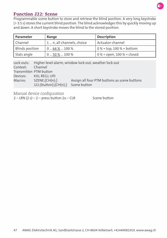
47 AWAG Elektrotechnik AG, Sandbüelstrasse 2, CH-8604 Volketswil, +41449081919, www.awag.ch
Function J22: SceneProgrammable scene button to store and retrieve the blind position. A very long keystroke (> 3.5 s) stores the current blind position. The blind acknowledges this by quickly moving up and down. A short keystroke moves the blind to the stored position.
Parameter Range Description
Channel 1 … n, all channels, choice Actuator channel
Blinds position 0 … 64 % … 100 % 0 % = top, 100 % = bottom
Slats angle 0 … 50 % … 100 % 0 % = open, 100 % = closed
Lock-outs: Higher-level alarm, window lock-out, weather lock-out Context: ChannelTransmitter: PTM buttonDevices: KXJ, REGJ, UPJMacros: SZENE;[CH{n};] Assign all four PTM buttons as scene buttons J22;{button};[CH{n};] Scene button
Manual device configuration2 – LRN (2 s) – 2 – press button 2x – CLR Scene button

Omnio. Intelligent building automation. 48
Switching functions
Extension inputSome actuators have an extension input, to which conventionally wired switches and push buttons can be connected. It is configured like a normal radio transmitter, it must also be pressed twice during manual programming. By default, the Function s05: steP switch (aw20) is set. In E-Tool, the extension input is always located at position 1 of the paired senders and can’t be deleted.
The extension input can also be used as an independent binary input (1-channel button in-terface) without switching the actuator’s relay. In this case, the parameter Output of Func-tion s05: steP switch (aw20) must be disabled. The device property eXtension inPut telegRam tyPe determines the type of telegram that is sent when operating the extension input.
DevicesUPS230/10, miniS01

49 AWAG Elektrotechnik AG, Sandbüelstrasse 2, CH-8604 Volketswil, +41449081919, www.awag.ch
Function S01: Switch with rockerSwitch the output on and off via a rocker. This is a combination of functions S02 and S03. Each rocker-button is programmed as Function s02: switch on and Function s03: switch oFF respectively, and can be configured with the corresponding delay times.
Parameter Range Description
Channel 1 … n, choice Actuator channel
Output on, off Action on button I
On delay 0 s … 60 h Switch on delay
Off delay 0 s … 60 h Switch off delay
Context: ChannelTransmitter: PTM rockerDevices: KS, miniS01, REGS, UPSMacros: S01;{rocker};[CH{n};]
Manual device configuration0 – LRN (2 s) – 0 – press rocker 2x – CLR Switch with rocker (O = off, I = on)0 – LRN (2 s) – 1 – press rocker 2x – CLR Switch with rocker (O = on, I = off)On delay see Function s02: switch on
Off delay see Function s03: switch oFF
0 – LRN (2 s) – 7 – press rocker 2x – CLR Switch with rocker, staircase light fct. onOff delay see device property staiRcase light duRation
Function S02: Switch onSwitch on the output via a push-button. Additionally, an on delay from 1 second to 60 hours can be configured. The function is retriggerable, i.e. a subsequent keystroke restarts the on delay.
Parameter Range Description
Channel 1 … n, choice Actuator channel
On delay 0 s … 60 h Switch on delay
Context: ChannelTransmitter: PTM button, PIR (EEP: A5-07-03)Devices: KS, miniS01, REGS, UPSMacros: S02;{button};[CH{n};] (button) S02;[CH{n};] (PIR)
Manual device configuration0 – LRN (2 s) – 2 – press button 2x – CLR Switch on with button0 – LRN (2 s) – 2 – LRN-button PIR – CLR Switch on with PIR

Omnio. Intelligent building automation. 50
On delay = time base x multiplier according to the following scheme:8 – LRN (2 s) – [time base] – press button 2x – [multiplier] – press button 2x – CLR
8 – LRN (2 s) – 0 – button 2 x – [0…15] … 0 … 15 s in 1 s – steps8 – LRN (2 s) – 1 – button 2 x – [1…15] … 4 … 60 s in 4 s – steps8 – LRN (2 s) – 2 – button 2 x – [1…15] … 15 … 225 s in 15 s – steps8 – LRN (2 s) – 3 – button 2 x – [1…15] … 1 … 15 min in 1 min – steps8 – LRN (2 s) – 4 – button 2 x – [1…15] … 4 … 60 min in 4 min – steps8 – LRN (2 s) – 5 – button 2 x – [1…15] … 15 … 225 min in 15 min – steps8 – LRN (2 s) – 6 – button 2 x – [1…15] … 1 … 15 h in 1 h – steps8 – LRN (2 s) – 7 – button 2 x – [1…15] … 4 … 60 h in 4 h – steps
Function S03: Switch offSwitch off the output via a push-button. Additionally, an off delay from 1 second to 60 hours can be configured. The function is retriggerable, i.e. a subsequent keystroke restarts the off delay.
Parameter Range Description
Channel 1 … n, choice Actuator channel
Off delay 0 s … 60 h Switch off delay
Context: ChannelTransmitter: PTM buttonDevices: KS, miniS01, REGS, UPSMacros: S03;{button};[CH{n};]
Manual device configuration0 – LRN (2 s) – 3 – press button 2x – CLR Switch off
Off delay = time base x multiplier according to the following scheme:8 – LRN (2 s) – [time base] – press button 2x – [multiplier] – press button 2x – CLR
8 – LRN (2 s) – 0 – button 2 x – [0…15] … 0 … 15 s in 1 s – steps8 – LRN (2 s) – 1 – button 2 x – [1…15] … 4 … 60 s in 4 s – steps8 – LRN (2 s) – 2 – button 2 x – [1…15] … 15 … 225 s in 15 s – steps8 – LRN (2 s) – 3 – button 2 x – [1…15] … 1 … 15 min in 1 min – steps8 – LRN (2 s) – 4 – button 2 x – [1…15] … 4 … 60 min in 4 min – steps8 – LRN (2 s) – 5 – button 2 x – [1…15] … 15 … 225 min in 15 min – steps8 – LRN (2 s) – 6 – button 2 x – [1…15] … 1 … 15 h in 1 h – steps8 – LRN (2 s) – 7 – button 2 x – [1…15] … 4 … 60 h in 4 h – steps
Function S04: PulseSwitch on the output for a pulse period of 1 second to 60 hours via a push-button. The func-tion is non-retriggerable, i.e. subsequent keystrokes during the pulse period are ignored. It can be defined whether the output is switched off or the pulse period keeps on running when the button is released. Additionally, the output can be inverted as well.

51 AWAG Elektrotechnik AG, Sandbüelstrasse 2, CH-8604 Volketswil, +41449081919, www.awag.ch
Parameter Range Description
Channel 1 … n Actuator channel
Puls duration 1 s … 3 s … 60 h Puls duration
Off on release yes, no Behaviour on release of button
Output mode normal, inverted Normal or inverted mode
Context: ChannelTransmitter: PTM buttonDevices: KS, miniS01, REGS, UPSMacros: S04;{button};[CH{n};]
Manual device configuration0 – LRN (2 s) – 6 – press button 2x – CLR Doorbell function 3 s, off on release0 – LRN (2 s) – 14 – press button 2x – CLR Pulse 10 s, no change on release of button
Pulse = time base x multiplier according to the following scheme:8 – LRN (2 s) – [time base] – press button 2x – [multiplier] – press button 2x – CLR
8 – LRN (2 s) – 8 – button 2 x – [0…15] … 0 … 15 s in 1 s – steps8 – LRN (2 s) – 9 – button 2 x – [1…15] … 4 … 60 s in 4 s – steps8 – LRN (2 s) – 10 – button 2 x – [1…15] … 15 … 225 s in 15 s – steps8 – LRN (2 s) – 11 – button 2 x – [1…15] … 1 … 15 min in 1 min – steps8 – LRN (2 s) – 12 – button 2 x – [1…15] … 4 … 60 min in 4 min – steps8 – LRN (2 s) – 13 – button 2 x – [1…15] … 15 … 225 min in 15 min – steps8 – LRN (2 s) – 14 – button 2 x – [1…15] … 1 … 15 h in 1 h – steps8 – LRN (2 s) – 15 – button 2 x – [1…15] … 4 … 60 h in 4 h – steps9 – LRN (2 s) – 8 – press button 2x – 0 – press button 2x – CLR Invert output
Function S05: Step switch (AW20)Step switch with adjustable delay times. Each time the button is pressed, the state of the output changes. On and off delay times of 1 second upto 60 hours can be set. The function is retriggerable, i.e. pressing the button again increases the delay time.
For a conventionally wired Scheme-3 circuit connected to the extension input, the para-meter Mode must be set to switch. The parameter Activation must be deactivated if the extension input is used as independent binary input (1-channel push-button interface). Then the relay is not switched upon actuating the input, but only a radio telegram is sent.
Parameter Range Description
Channel 1 … n Actuator channel
On delay 0 s … 15 min Switch on delay
Off delay 0 s … 15 min Switch off delay
Mode button, switch (edge) Edge detection on/off
Output enabled, disabled disable output

Omnio. Intelligent building automation. 52
Context: ChannelTransmitter: PTM buttonDevices: KS, miniS01, REGS, UPSMacros: S05;{button};[CH{n};]
Manual device configuration0 – LRN (2 s) – 4 – press button 2x – CLR Step switch (AW20)0 – LRN (2 s) – 13 – press button 2x –CLR Step switch (edge)
On delay = time base x multiplier according to the following scheme:8 – LRN (2 s) – [time base] – press button 2x – [multiplier] – press button 2x – CLR8 – LRN (2 s) – 0 – button 2 x – [0…15] … 0 … 15 s in 1 s – steps8 – LRN (2 s) – 1 – button 2 x – [1…15] … 4 … 60 s in 4 s – steps8 – LRN (2 s) – 2 – button 2 x – [1…15] … 15 … 225 s in 15 s – steps8 – LRN (2 s) – 3 – button 2 x – [1…15] … 1 … 15 min in 1 min – steps
Off delay = time base x multiplier according to the following scheme:9 – LRN (2 s) – [time base] – press button 2x – [multiplier] – press button 2x – CLR9 – LRN (2 s) – 0 – button 2 x – [0…15] … 0 … 15 s in 1 s – steps9 – LRN (2 s) – 1 – button 2 x – [1…15] … 4 … 60 s in 4 s – steps9 – LRN (2 s) – 2 – button 2 x – [1…15] … 15 … 225 s in 15 s – steps9 – LRN (2 s) – 3 – button 2 x – [1…15] … 1 … 15 min in 1 min – steps
Extension input UPS230/10:14 – LRN (2 s) – 0 – LRN Push-button connected to ext. input14 – LRN (2 s) – 1 – LRN Switch connected to extension input14 – LRN (2 s) – 2 – LRN Disable extension input
Function S06: Sequential push-buttonSequential push-button with adjustable time delays. Switch on the output as long as the button is pressed. An on delay and off delay from 1 second to 60 hours can be configured. Is the button released during the on delay, the output doesn’t change its state. Additionally, the output can be inverted.
Parameter Range Description
Channel 1 … n, choice Actuator channel
On delay 0 s … 60 h Switch on delay
Off delay 0 s … 60 h Switch off delay
Output mode normal, inverted Normal: on while pressedInverted: off while pressed
Context: ChannelTransmitter: PTM button, KSM Key-Card Switch, PIR (EEP: A5-07-03)Devices: KS, miniS01, REGS, UPSMacros: S06;{button};[CH{n};] (button) S06;[CH{n};] (Key-Card Switch, PIR)

53 AWAG Elektrotechnik AG, Sandbüelstrasse 2, CH-8604 Volketswil, +41449081919, www.awag.ch
Manual device configuration0 – LRN (2 s) – 5 – press button 2x – CLR Sequential push-button (PTM)0 – LRN (2 s) – 5 – insert card 2x – CLR Sequential push-button (KSM)0 – LRN (2 s) – 5 – LRN-button PIR – CLR Sequential push-button (PIR)
Delay times see Function s05: steP switch (aw20)
9 – LRN (2 s) – 8 – press button 2x – 0 – Taste 2x – CLR Invert output
Function S07: BlinkingWhen a button is pressed, the output starts flashing. The on and off duration can be set from 1 second to 15 minutes. Alternatively, you can also use the staircase lighting dura-tion for symmetrical flashing, see device property staiRcase light duRation. In addition, the behaviour when the button is pressed again can be determined. If this parameter is set to blinking, the flashing must be stoped via another key, e.g. with the Function s03: switch oFF. This is used, for example, with alarms that must be explicitly acknowledged for safety reasons.
Parameter Range Description
Channel 1 … n Actuator channel
On duration 1 s … 9 s … 15 min On duration
Off duration 1 s … 12 s … 15 min Off duration
Subsequent keystroke off, on, keep state, blink Action on subsequent keystroke
Time base on-/off-duration,staircase light
Time base for blinking frequen-cy
Context: ChannelTransmitter: PTM buttonDevices: KS, miniS01, REGS, UPSMacros: S07;{button};[CH{n};]
Manual device configurationBlinking with staircase light duration, no stop on subsequent keystroke1 – LRN (2 s) – 14 – press button 2x – CLRBlinking frequency see device property staiRcase light duRation
Blinking with on/off duration, stop on subsequent keystroke1 – LRN (2 s) – 15 – press button 2x – CLRBlinking frequency see delay times in Function s05: steP switch (aw20)

Omnio. Intelligent building automation. 54
Function S08: Short/long with push-buttonFunction 1 is performed on a short (< 1 s) keystroke, function 2 is performed on releasing the button after a long keystroke. The following combinations are possible:
Timer-off function 1 = staircase light function 2 = offOn-off function 1 = on function 2 = offOff-on function 1 = off function 2 = on.
Parameter Range Description
Channel 1 … n Actuator channel
Type timer-off, on-off, off-on Combination of functions
Context: ChannelTransmitter: PTM buttonDevices: KS, REGS, UPSMacros: S08;{button};[CH{n};]
Manual device configuration0 – LRN (2 s) – 10 – press button 2x – CLR timer-off (staircase light)0 – LRN (2 s) – 11 – press button 2x – CLR On-off0 – LRN (2 s) – 12 – press button 2x – CLR Off-on
Time delay see device property staiRcase light duRation
Function S09: Window contactMonitor a window or door via a window contact. The output is switched on when the mo-nitored window opens and vice versa. Programmed window contacts and window handles are logical AND-linked. The output is only switched off when all windows are closed.
Window contacts send a heartbeat signal every 15 minutes. After one hour without heart-beat signal the state window open is assumed and the window lock-out will be activated.
Note: Defective window contacts must be deprogrammed, otherwise they block the output.
Parameter Range Description
Channel 1 … n Actuator channel
Context: ChannelTransmitter: STM window contact (EEP: D5-00-01)Devices: KS, miniS01, REGS, UPSMacros: S09;[CH{n};]
Manual device configuration1 – LRN (2 s) – 0 – press LRN on sensor – CLR Window contact13 – LRN (2 s) – 14 – press LRN Deprogram dead window contacts

55 AWAG Elektrotechnik AG, Sandbüelstrasse 2, CH-8604 Volketswil, +41449081919, www.awag.ch
Function S10: Window handleMonitor a window or sliding door via a window handle. The output is switched on when the monitored window opens and vice versa. Programmed window contacts and window handles are logical AND-linked. The output is only switched off when all windows are clo-sed.
Window and door handles have three states: closed, open and tilted. It can be determined, whether tilted counts as window open or window closed.
Parameter Range Description
Channel 1 … n Actuator channel
Tilted counts as open, closed Evaluation of state tilted
Context: ChannelTransmitter: Hoppe window and door handles (EEP: F6-10-00)Devices: KS, miniS01, REGS, UPSMacros: S10;[CH{n};]
Manual device configuration1 – LRN (2 s) – 7 – turn handle 2x – CLR Window handle, tilted = open1 – LRN (2 s) – 8 – turn handle 2x – CLR Window handle, tilted = closed
Function S11: Central onSwitch on all channels.
Context: DeviceTransmitter: PTM button, PIR (EEP: A5-07-03)Devices: REGS, UPS230/12Macros: S11;{button}; (button) S11; (PIR)
Manual device configuration1 – LRN (2 s) – 3 – press button 2x – CLR Central on with button1 – LRN (2 s) – 3 – LRN-button PIR – CLR Central on with PIR
Function S12: Central offSwitch off all channels.
Context: DeviceTransmitter: PTM buttonDevices: REGS, UPS230/12Macros: S12;{button};
Manual device configuration1 – LRN (2 s) – 2 – press button 2x – CLR Central off

Omnio. Intelligent building automation. 56
Function S20: Toilet fanStep switch with toilet fan function. This function can be used in toilets for controlling the light and the fan via a push-button. The first keystroke switches channel 1 (light) on imme-diately and channel 2 (fan) on after an adjustable time delay. The second keystroke switches channel 1 off immediately and channel 2 off after an adjustable time delay. The time delay is up to 15 minutes.
Parameter Range Description
Channel 1-2, 3-4, 5-6, 7-8 Channel pair of actuator
On delay 0 s … 3 min … 15 min Switch on delay channel 2
Off delay 0 s … 5 min … 15 min Switch off delay channel 2
Context: Channel pair (ch1-ch2, ch3-ch4, ch5-ch6, ch7-ch8)Transmitter: PTM buttonDevices: REGS, UPS230/12Macros: S20;{button};[CH{n};]
Manual device configuration1 – LRN (2 s) – 1 – press button 2x – CLR ch1: toggle ch2: 3/5 min1 – LRN (2 s) – 4 – press button 2x – CLR ch1: toggle ch2: 1/3 s
On delay = time base x multiplier according to the following scheme:8 – LRN (2 s) – [time base] – press button 2x – [multiplier] – press button 2x – CLR8 – LRN (2 s) – 4 – button 2 x – [0…15] … 0 … 15 s in 1 s – steps8 – LRN (2 s) – 5 – button 2 x – [1…15] … 4 … 60 s in 4 s – steps8 – LRN (2 s) – 6 – button 2 x – [1…15] … 15 … 225 s in 15 s – steps8 – LRN (2 s) – 7 – button 2 x – [1…15] … 1 … 15 min in 1 min – steps
Off delay = time base x multiplier according to the following scheme:9 – LRN (2 s) – [time base] – press button 2x – [multiplier] – press button 2x – CLR9 – LRN (2 s) – 4 – button 2 x – [0…15] … 0 … 15 s in 1 s – steps9 – LRN (2 s) – 5 – button 2 x – [1…15] … 4 … 60 s in 4 s – steps9 – LRN (2 s) – 6 – button 2 x – [1…15] … 15 … 225 s in 15 s – steps9 – LRN (2 s) – 7 – button 2 x – [1…15] … 1 … 15 min in 1 min – steps

57 AWAG Elektrotechnik AG, Sandbüelstrasse 2, CH-8604 Volketswil, +41449081919, www.awag.ch
Function S21: Toilet fan PIRToilet fan function with PIR. This function is used, among other things, to automatically control lights and fans in toilets via a motion detector (PIR). The ON signal switches on channel 1 (light) immediately and channel 2 (toilet fan) after an adjustable delay time. The OFF-signal switches off channel 1 and channel 2 after an adjustable delay time.
Parameter Range Description
Channel 1-2, 3-4, 5-6, 7-8 Channel pair of actuator
On delay 0 s … 3 min … 15 min Switch on delay channel 2
Off delay 0 s … 5 min … 15 min Switch off delay channel 2
K1 off delay none, 10 s, 1 min, 3 min Switch off delay channel 1
Context: Channel pair (ch1-ch2, ch3-ch4, ch5-ch6, ch7-ch8)Transmitter: PIR (EEP: A5-07-03)Devices: REGS, UPS230/12Macros: S21;[CH{n};]
Manual device configuration1 – LRN (2 s) – 5 – LRN-Taste PIR – CLR Toilet fan PIR, 3 / 5 min1 – LRN (2 s) – 6 – LRN-Taste PIR – CLR Toilet fan PIR, 1s / 1 min
The delay times can’t be set manually.
Function S22: SceneProgrammable scene button to store and retrieve the output states. A very long keystroke (> 3.5 s) stores the states of all outputs. A short keystroke restores the states of all outputs.
Context: DeviceTransmitter: PTM buttonDevices: KS, miniS01, REGS, UPSMacros: SZENE; Assign all four PTM buttons as scene buttons S22;{button}; Scene button
Manual device configuration2 – LRN (2 s) – 2 – press button 2x – CLR Scene button

Omnio. Intelligent building automation. 58
Thermostat functions
LoggerAll Omnio thermostat actuators come with a built-in datalogger which records all import-ant parameters over an adjustable period of time. Thus, the correct function of the heating control can be confirmed during commissioning on site.
The logger is called up via the „Log Viewer ...“ button. This button becomes visible as soon as the device parameter loggeR time Range is selected:
The recorded data can be displayed channel by channel via «SCAN» and saved for further processing via a «CSV» as a CSV-file. There are 70 memory locations per channel, which are constantly overwritten with the latest values.
Note: The recorded values are stored in RAM and are lost in the event of a power failure or restart of the device.

59 AWAG Elektrotechnik AG, Sandbüelstrasse 2, CH-8604 Volketswil, +41449081919, www.awag.ch
Function H01: Room sensorRoom sensor for controlling the temperature of individual rooms using a 2-point controller with hysteresis. The desired room temperature is set on the room sensor via the setpoint. The room sensor sends temperature (current value) and setpoint via radio to the thermos-tat actuator. Since the setpoint is transmitted relative to the setpoint range, this range must also be specified, see device property setPoint Range FoR h01. If the thermostat actuator does not receive a room sensor signal for more than one hour, it will switch to emergency mode, see device property emeRgency mode*.
Parameter Range Description
Channel 1 … n Actuator channel
EEP A5-10-10/11/12A5-10-03/04/05/06/0A
EnOcean Equipment Profile
Hysteresis 0 … 0.8 K … 2.4 K Hysteresis of 2-point controller
Context: ChannelTransmitter: RTF16x (EEP: A5-10-03/04/05/06/0A/10/11/12)Devices: REGH, UPHMacros: H01;[CH{n};]
Manual device configuration0 – LRN (2 s) – 0 – press LRN on RTF – CLR RTF16x, EEP A5-10-100 – LRN (2 s) – 6 – press LRN on RTF – CLR Room sensor, EEP A5-10-03
Hysteresis8 – LRN (2 s) – 0 – press LRN – CLR No hysteresis8 – LRN (2 s) – 2 – press LRN – CLR 0.3 K8 – LRN (2 s) – 3 – press LRN – CLR 0.5 K8 – LRN (2 s) – 5 – press LRN – CLR 0.8 K8 – LRN (2 s) – 9 – press LRN – CLR 1.4 K8 – LRN (2 s) – 13 – press LRN – CLR 2.0 K
Function H02: Heating Control PanelProgram all four buttons of a double rocker with a predefined setpoint. A set point shift according to Function h03: setPoint shiFting is assigned to each button:
AO: -0 K Comfort mode AI: -2 K StandbyBO: -4 K Night mode BI: 8 °C Off (frost protection).
Parameter Range Description
Channel all channels, 1 … n Actuator channel
Duration endless, 1 … 15 h Duration of new setpoint
Context: ChannelTransmitter: PTM double rockerDevices: REGH, UPHMacros: H02;[CH{n};]

Omnio. Intelligent building automation. 60
Function H03: Setpoint shiftingSet the active setpoint to a new value via a button. The new setpoint can be specified rela-tive to the current setpoint range (+/- 9.9 K) or absolute (8 … 37.9 ° C). In addition, one can set the duration of the new setpoint (1 … 15 hours or endless). The following predefined setpoint are available: -0 K (Comfort); -2 K (standby); -4 K (night reduction); 8 ° C (off, frost protection).
Parameter Range Description
Channel all channels, 1 … n Actuator channel
Mode comfort, standby, night, off, special setting
Predefined setpoints
OffsetRelative -9.9 … 0 … 9.9 K Relative setpoint shifting
Absolute 8 … 37.9 °C Absolute setpoint
Duration endless, 1 … 15 h Duration of new setpoint
Context: ChannelTransmitter: PTM button, PIR (EEP: A5-07-03)Devices: REGH, UPHMacros: H03;{button};[CH{n};] (button)
Manual device configuration0 – LRN (2 s) – 1 – press rocker 2x – CLR O = comfort, I = standby0 – LRN (2 s) – 2 – press rocker 2x – CLR O = night, I = off7 – LRN (2 s) – 7 – press rocker 2x – CLR Swap buttons O and I
Offset9 – LRN (2 s) – 7 – press button 2x – 2 – press button 2x – CLR -8 K9 – LRN (2 s) – 5 – press button 2x – 9 – press button 2x – CLR -4 K (night)9 – LRN (2 s) – 4 – press button 2x – 12 – press button 2x – CLR -2 K (standby)9 – LRN (2 s) – 4 – press button 2x – 6 – press button 2x – CLR -1 K9 – LRN (2 s) – 0 – press button 2x – 0 – press button 2x – CLR 0 K (comfort)9 – LRN (2 s) – 0 – press button 2x – 6 – press button 2x – CLR +1 K9 – LRN (2 s) – 0 – press button 2x – 12 – press button 2x – CLR +2 K9 – LRN (2 s) – 1 – press button 2x – 9 – press button 2x – CLR +4 K9 – LRN (2 s) – 9 – press button 2x – 9 – press button 2x – CLR 8 °C (off)9 – LRN (2 s) – 10 – press button 2x – 0 – press button 2x – CLR 10 °C9 – LRN (2 s) – 10 – press button 2x – 6 – press button 2x – CLR 12 °C9 – LRN (2 s) – 10 – press button 2x – 12 – press button 2x – CLR 14 °C
Duration8 – LRN (2 s) – 0 – press button 2x – CLR endless8 – LRN (2 s) – [1…15] – press button 2x – CLR 1 … 15 hours
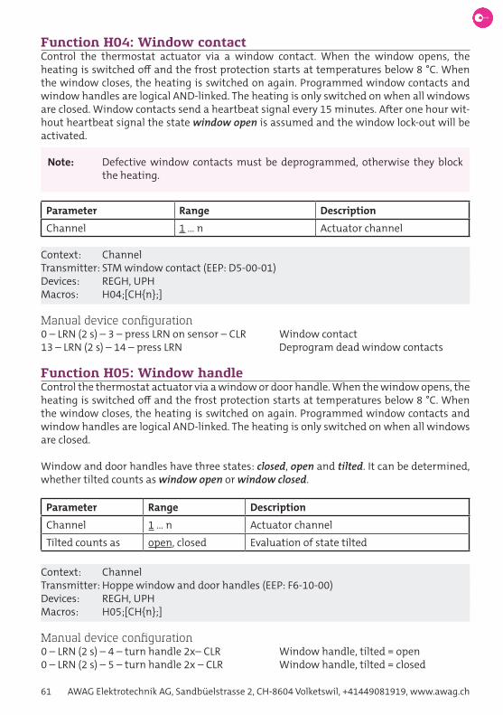
61 AWAG Elektrotechnik AG, Sandbüelstrasse 2, CH-8604 Volketswil, +41449081919, www.awag.ch
Function H04: Window contactControl the thermostat actuator via a window contact. When the window opens, the heating is switched off and the frost protection starts at temperatures below 8 °C. When the window closes, the heating is switched on again. Programmed window contacts and window handles are logical AND-linked. The heating is only switched on when all windows are closed. Window contacts send a heartbeat signal every 15 minutes. After one hour wit-hout heartbeat signal the state window open is assumed and the window lock-out will be activated.
Note: Defective window contacts must be deprogrammed, otherwise they block the heating.
Parameter Range Description
Channel 1 … n Actuator channel
Context: ChannelTransmitter: STM window contact (EEP: D5-00-01)Devices: REGH, UPHMacros: H04;[CH{n};]
Manual device configuration0 – LRN (2 s) – 3 – press LRN on sensor – CLR Window contact13 – LRN (2 s) – 14 – press LRN Deprogram dead window contacts
Function H05: Window handleControl the thermostat actuator via a window or door handle. When the window opens, the heating is switched off and the frost protection starts at temperatures below 8 °C. When the window closes, the heating is switched on again. Programmed window contacts and window handles are logical AND-linked. The heating is only switched on when all windows are closed.
Window and door handles have three states: closed, open and tilted. It can be determined, whether tilted counts as window open or window closed.
Parameter Range Description
Channel 1 … n Actuator channel
Tilted counts as open, closed Evaluation of state tilted
Context: ChannelTransmitter: Hoppe window and door handles (EEP: F6-10-00)Devices: REGH, UPHMacros: H05;[CH{n};]
Manual device configuration0 – LRN (2 s) – 4 – turn handle 2x– CLR Window handle, tilted = open0 – LRN (2 s) – 5 – turn handle 2x – CLR Window handle, tilted = closed

Omnio. Intelligent building automation. 62
Function H06: Second setpointUsing an additional room temperature sensor (e.g. Omnio RTF161) as second setpoint. The following EEP are supported: A5-10-10 … 12. Only the setpoint is used, the temperature is ignored. The value is displayed in the device property setPoint 2* and it is valid for one chan-nel or all channels of the thermostat actuator. The default value is 18 °C.
The switchover from the first to the second set point is done with either Function h07: setPoint switchoveR with RockeR or Function h08: setPoint switchoveR with key-caRd switch.
Parameter Range Description
Channel all channels, 1 … n Actuator channel
Context: ChannelTransmitter: RTF16x (EEP: A5-10-10/11/12)Devices: REGH, UPHMacros: H06;[CH{n};]
Manual device configuration0 – LRN (2 s) – 7 – press LRN on RTF – CLR Second setpoint, 1 channel1 – LRN (2 s) – 7 – press LRN on RTF – CLR Second setpoint, all channels
Function H07: Setpoint switchover with rockerChoose the first or second setpoint via a rocker. In case no second setpoint has been pro-grammed via Function h06: second setPoint, the value defaults to 18 °C.
Parameter Range Description
Channel all channels, 1 … n Actuator channel
Setpoint setpoint 1, setpoint 2 Action on button I
Context: ChannelTransmitter: PTM rockerDevices: REGH, UPHMacros: H07;{rocker};[CH{n};]
Manual device configuration0 – LRN (2 s) – 8 – press rocker 2x – CLR Setpoint switchover (one channel)1 – LRN (2 s) – 8 – press rocker 2x – CLR Setpoint switchover (all channels)

63 AWAG Elektrotechnik AG, Sandbüelstrasse 2, CH-8604 Volketswil, +41449081919, www.awag.ch
Function H08: Setpoint switchover with key-card switchChoose the first or second setpoint via a key-card switch. Inserting the card activates the first setpoint, removing the card activates the second setpoint. In case no second setpoint has been programmed via Function h06: second setPoint, the value defaults to 18 °C.
Parameter Range Description
Channel all channels, 1 … n Actuator channel
Context: ChannelTransmitter: KSM Key-Card SchalterDevices: REGH, UPHMacros: H08;[CH{n};]
Manual device configuration0 – LRN (2 s) – 9 – insert card 2x – CLR Setpoint switchover (one channel)1 – LRN (2 s) – 9 – insert card 2x – CLR Setpoint switchover (all channels)
Function H09: Temperature sensorIf the user is not allowed to adjust the set point locally or if this is specified by a higher-level system, then a temperature sensor without setpoint can be used. The standard setpoint is 22 °C and can only be adjusted using E-Tool, see also device property deFault setPoint. The hysteresis is 0.8 K by default, it can only be adjusted by E-Tool, see also the device property deFault hysteResis.
Note: This function must not be used together with function H01: Room sensor!
Parameter Range Description
Channel 1 … n Actuator channel
EEP A5-10-01…0D / A5-02-05A5-10-10…14A5-04-03
RTF16x, RTF261RTF16xRTF100
Context: ChannelTransmitter: RTF100, RTF16x, RTF261 (EEP: A5-04-03, A5-10-01…0D, A5-10-10…14)Devices: REGH, UPHMacros: H09;[CH{n};]
Manual device configuration0 – LRN (2 s) – 10 – press LRN on RTF – CLR Temperature sensor, EEP: A5-10-01…0D0 – LRN (2 s) – 11 – press LRN on RTF – CLR Temperature sensor, EEP: A5-10-10…140 – LRN (2 s) – 12 – press LRN on RTF – CLR Temperature sensor, EEP: A5-04-03

Omnio. Intelligent building automation. 64
Function H10: Temperature as setpointTemperature folllower. The local temperature (slave) is regulated according to a preset tem-perature (master). The master is programmed as Function h09: temPeRatuRe sensoR on the same channel as the slave.
Note: This function must not be used together with function H01: Room sensor!
Parameter Range Description
Channel all channels, 1 … n Actuator channel
EEP A5-10-01 … 0D / A5-02-05 RTF16x
Context: ChannelTransmitter: RTF16x (EEP: A5-10-01 … 0D / A5-02-05)Devices: REGH, UPHMacros: H10;[CH{n};]
Manual device configuration0 – LRN (2 s) – 14 – press LRN on RTF – CLR Temperature as SP, EEP: A5-10-01 … 0D

65 AWAG Elektrotechnik AG, Sandbüelstrasse 2, CH-8604 Volketswil, +41449081919, www.awag.ch
Weather station
The Omnio weather station consists of the weather sensor P04x-RS485 and the weather evaluation unit XFJ, which is connected through its integrated RS485-interface. The weat-her evaluation unit XFJ is able to convert the captured weather data to EnOcean telegrams. This way blinds can be pilot-controlled and protected against thunderstorms.
Four individual signals are available:
Channel 1: Weather raw data according to EEP A5-13-01…06.Channel 2: Alarm in case of failure of the weather sensor.Channel 3: Day/night signal.Channel 4: Up-/down signal for blinds which is calculated from the weather data from wind, rain and sun. The switching thresholds and delay times can be adjus- ted as required.
Up to eight weather evaluation units can be connected to the weather sensor in order to cover different zones within a building.
Block diagram
DevicesWeather sensor P04x-RS485Weather evaluation unit XFJPower supply 24VDC for sensor and evaluation unitBlind actuators KXJ, REGJ, UPJ
ConfigurationSee Function j11: weatheR station.

Omnio. Intelligent building automation. 66
Device properties
Note: Device properties marked with an asterisk (*) can’t be edited.
Note: The default value is underlined.
Action on alarmBehaviour of the blind in case of an alarm. This device property can only be set with EEP (EnOcean Equipment Profile) D2-05-0x (CMD 5 – Set parameters) or with E-Tool.
Range: Nothing (If the blind received a positioning command before the alarm signal, it is carried out despite the alarm) Immediate stop Go up Go down Shading position 1, 2, 3Context: ChannelDevices: KXJ, REGJ, UPJProperty: P#1030 0 (nothing) … 6 (shading position 3)
Manual device configurationNot possible
Active power*Current power consumption in Watt.
Range: 0 … 3680 WContext: DeviceDevices: miniS01
Active set point*Indicates which of the two setpoints is active. The current setpoints can be found in the device properties setPoint 1* and setPoint 2*.
Range: Setpoint 1 Setpoint 2Context: ChannelDevices: REGH, UPH
AddressSets the state of a REG device within an Omnio E-Bridge.
Note: This parameter can be adjusted by E-Tool in FactoRy mode only.

67 AWAG Elektrotechnik AG, Sandbüelstrasse 2, CH-8604 Volketswil, +41449081919, www.awag.ch
Range: Master, Slave 1 … 31, Standalone, AutodetectContext: DeviceDevices: REGProperty: P#0117 0 (Master) … 33 (Autodetect)
Manual device configuration2 – CLR (2 s) – 0 – LRN Master2 – CLR (2 s) – 1 … 15 – LRN Slave 1 … 153 – CLR (2 s) – 0 … 15 – LRN Slave 16 … 314 – CLR (2 s) – 0 – LRN Standalone4 – CLR (2 s) – 1 – LRN Autodetect
Automatic end positionEnd position of the blind after a down-command in automatic mode. See also Function j09: temPeRatuRe sensoR.
Range: Lower end position, Shading position 1, 2, 3Context: ChannelDevices: KXJ, REGJ, UPJProperty: P#1010 0 (lower end position) … 3 (shading position 3)
Manual device configurationApplies to all channels of a device, individual shading positions can only be set via E-Tool.10 – LRN (2 s) – 0 – LRN Lower end position, slats closed10 – LRN (2 s) – 1 – LRN Shading position 110 – LRN (2 s) – 2 – LRN Shading position 210 – LRN (2 s) – 3 – LRN Shading position 3
Automatic suppression timer*Indicates the remaining time in minutes of the automatic mode suppression.
Range: 3 minutesContext: ChannelDevices: KXJ, REGJ, UPJ
Azimuth*Azimuth of the sun in degrees. Depending on the sensor type this information is not avai-lable.
Range: 0 … 360.0 °Context: DeviceDevices: XFJ
Base ID EnOcean base ID. A maximum of 128 (0x80) devices can be addressed via the base ID, which is why each base ID ends either with 0x00 or 0x80.
Note: The base ID can be changed a maximum of ten times, after which a final lock

Omnio. Intelligent building automation. 68
takes effect.
Range: 0xFF800000 … 0xFFFFFF80Context: DeviceDevices: APG, TST, USBProperty: P#0111 FF800000 … FFFFFF80
Manual device configurationNot possible.
Blinds command (F01)Enable/disable blinds command, see also device property blinds mode.
Range: off, onContext: DeviceDevices: XFJProperty: P#2050 0 (off), 1 (on)
Blinds modeDefines which events (wind, rain, or sun alarm) trigger the up/down commands. The com-mands are sent either cyclic every 10 seconds (always) ore once three times within 3 seconds (pulse). The switching thresholds and delay times can be adjusted as required.
Range: up on wind (repeated) up on rain (repeated) up on wind or rain (repeated) wind, rain, sunshine up when cloudy, down on sunshine (pulse) up on rain, down when dry (pulse)Context: DeviceDevices: XFJProperty: P#2051 0 (up on wind) … 5 (up on rain, down when dry)
Blinds position*Current position of the blind in percent: Upper end position = 0 %, lower end position = 100 %. If the position is unknown (e.g. after a power failure) the value is unknown. It will be updated once the blind reaches one of its end positions.
Range: 0 … 100 %, unknownContext: ChannelDevices: KXJ, REGJ, UPJ
Blinds runtimeRuntime of the blinds in hundredths of a second from the upper to the lower end position.
Range: 500 … 18000 … 30000 hundredths of a second (5 s … 3 Min. … 5 Min.)Context: Channel

69 AWAG Elektrotechnik AG, Sandbüelstrasse 2, CH-8604 Volketswil, +41449081919, www.awag.ch
Devices: KXJ, REGJ, UPJProperty: P#1006 500 … 30000
Manual device configuration5 – LRN (2 s) – 3 – LRN Duration = 300 Sekunden
Option a)Measure the runtime of the blind with a stopwatch (1 … 299 s) and program each digit (hundreds – tens – units) according to the following scheme:5 – LRN (2 s) – [hundreds 0…2] – LRN – [tens 0…9] – LRN – [units 0…9] – LRN
Option b)Move the blinds to the upper end position and program the runtime automatically with the following procedure:5 – LRN (2 s) – 15 – LRN Blinds moves down automaticallyLRN press LRN when the blind reaches the lower end position
For both options, adjust the runtime if necessary: 5 – LRN (2 s) – 4 – LRN Reduce runtime by 1 second 5 – LRN (2 s) – 5 – LRN Extend runtime by 1 second5 – LRN (2 s) – 6 – LRN Reduce runtime by 10 seconds5 – LRN (2 s) – 7 – LRN Extend runtime by 10 seconds
Blinds sun directionThe weather sensor provides the sunlight intensity from east, south and west. This para-meter specifies the direction. See also device property sun west, south, east*.
Range: East, South, WestContext: DeviceDevices: XFJProperty: P#2053 0 (East) … 2 (West)
Blinds sun off delaySwitch-off delay of the sun alarm in seconds, see also device property blinds sun thReshold.
Range: 1 … 120 … 3600 sContext: DeviceDevices: XFJProperty: P#2055 0 … 3600
Blinds sun on delaySwitch-on delay of the sun alarm in seconds, see also device property blinds sun thReshold.
Range: 1 … 30 … 900 sContext: DeviceDevices: XFJProperty: P#2054 0 … 900

Omnio. Intelligent building automation. 70
Blinds sun thresholdThreshold for the sunlight intensity (BLINDS SUN DIRECTION) in kLux. If the value is excee-ding the threshold, the sun alarm is triggered after an adjustable time delay (blinds sun on delay) and a single down-command is sent. If the value drops below the threshold, the sun alarm is cleared after an adjustable time delay (blinds sun oFF delay). Depending on the device property blinds mode an up-command is sent.
Range: 2 … 40 … 80 kLuxContext: DeviceDevices: XFJProperty: P#2052 2 … 80
Blinds wind off delaySwitch off delay of the weather alarm by wind after a wind event in seconds. See also device property blinds wind thReshold.
Range: 1 … 60 … 900 sContext: DeviceDevices: XFJProperty: P#2058 1 … 900
Blinds wind on delaySwitch on delay of the weather alarm by wind after a wind event in seconds. See also device property blinds wind thReshold.
Range: 1 … 3 … 60 sContext: DeviceDevices: XFJProperty: P#2057 1 … 60
Blinds wind thresholdThreshold for the wind speed in m/s. If this value exceeds the threshold, the wind alarm is triggered after an adjustable delay time (blinds wind on delay) and an up-command is sent every 10 seconds. If the wind intensity falls below the threshold again, the wind alarm is de-activated after an adjustable delay time (blinds wind oFF delay). During the entire duration of the wind alarm, an up-command is sent every 10 seconds.
Range: 4 … 18 … 34 m/sContext: DeviceDevices: XFJProperty: P#2056 4 … 34
Bridge-Nr.Number of the Omnio E-Bridge. If several E-bridges (multi-bridge) are used in a project, these should be numbered consecutively for the sake of clarity.
Note: This property can only be adjusted in FactoRy mode of the Bridge Master via E-Tool.

71 AWAG Elektrotechnik AG, Sandbüelstrasse 2, CH-8604 Volketswil, +41449081919, www.awag.ch
Range: 0 … 255Context: DeviceDevices: REG MasterProperty: P#0118 0 … 255
Channel disabledEnable or disable a channel of an Omnio thermostat actuator.
Range: no, yesContext: ChannelDevices: REGH, UPH230Property: P#0305 0 (enabled), 1 (disabled)
Manual device configuration12 – LRN (2 s) – [see table below] – LRN
Channel 1 2 3 4 5 6 7 8
Disabled (yes) 0 2 4 6 8 10 12 14
Enabled (no) 1 3 5 7 9 11 13 15
Channels*Number of channels of the device.
Range: 1 … nContext: DeviceDevices: KD, KS, KXJ, REGH, REGJ, REGS, UPD, UPH, UPJ, UPS
Chip temperature*Temperature of the microprocessor in degrees Celsius. If the temperature exceeds 80 °C, the relay is switched off and locked for five minutes. During this time the red LED flashes. If the temperature drops below 75 °C the lockout is removed and the unit returns to normal operation mode. The device property temPeRatuRe monitoR* indicates this behaviour.
Range: 30 … 85 °CContext: DeviceDevices: miniS01
Clone countClones are needed to evaluate the feedback from a binary interface (such as an Astro ti-mer) in multi-channel Omnio devices. For example, the Venetian blind in the dining room (channel 1) at dawn should go all the way up, whereas the blind in the bedroom (channel 2) should only set the slats horizontal. Clones always send on the base id + offset 0x10 (clone 1) / 0x20 (clone 2) / 0x30 (clone 3).
Note: Depending on the number of transmission repetitions, plenty of telegrams may occur when using several clones.

Omnio. Intelligent building automation. 72
Range: 0, 1, 2, 3Context: DeviceDevices: TSTProperty: P#0295 0 … 3
Manual device configuration15 – LRN (2 s) – 9 – LRN No clone15 – LRN (2 s) – 10 – LRN 1 clone15 – LRN (2 s) – 11 – LRN 2 clones15 – LRN (2 s) – 12 – LRN 3 clones
Current monitor*Indicates whether the current is within the permissible range. If the current value exceeds 16 A, the relay is switched off and locked for thirty seconds. During this time the red LED flashes. After this time, the lockout is removed and the device returns to normal operation mode.
Note: Inrush currents are not affected.
Range: OK, overcurrentContext: DeviceDevices: miniS01
Current run*Current moving direction of the blind.
Range: none, upwards, downwardsContext: ChannelDevices: KXJ, REGJ, UPJ
Date*Current date in the form dd.mm.yy. Depending on the sensor type this information is not available.
Range: 01.01.00 … 31.12.99Context: DeviceDevices: XFJ
Day/night signal transmissionTransmission interval of the day/night signal. If the value changes, the signal is sent imme-diately, i.e. outside of the transmission interval.
Range: off, 3 s, 30 s, ~3 min, ~10 min, ~20 minContext: DeviceDevices: XFJProperty: P#2036 0 (off) … 5 (~20 min)

73 AWAG Elektrotechnik AG, Sandbüelstrasse 2, CH-8604 Volketswil, +41449081919, www.awag.ch
Day of week*Current day of week. Depending on the sensor type this information is not available.
Range: 1 … 7 (Monday … Sunday)Context: DeviceDevices: XFJ
Daytime*Indicates the daytime (day/night). The signal usually comes from a brightness sensor or an astro-timer. If no sensor is attached, the value displayed is unknown.
Range: Day, Night, unknownContext: DeviceDevices: KD, KS, REGS, UPD, UPS, XFJ
Dead time
a) Blind actuators:Waiting time between two reverse position commands of a blind.
Note: Some blind motors can be damaged if the dead time is set to 0! That‘s why the dead time can‘t be set to 0 with E-Tool.
b) Switch actuators:Rest time of the relay in zero position when switching over changeover contacts.
Range: 0, 400, 800, 1600 msContext: DeviceDevices: KXJ, REGJ, REGS12/04, UPJProperty: P#0313 1 (400 ms) … 3 (1600 ms) 0 is not allowed and an error is displayed in E-Tool!
Manual device configuration14 – LRN (2 s) – 6 – LRN 014 – LRN (2 s) – 7 – LRN 400 ms14 – LRN (2 s) – 8 – LRN 800 ms14 – LRN (2 s) – 9 – LRN 1600 ms
Default hysteresisDefault hysteresis, see also Function h09: temPeRatuRe sensoR.
Range: 0 … 0.8 … 2.4 KContext: DeviceDevices: REGH, UPHProperty: P#2044 0 (0) … 15 (2.4)

Omnio. Intelligent building automation. 74
Default setpointDefault setpoint when using temperature sensors without setpoint, see also Function h09: temPeRatuRe sensoR.
Range: 15.0 … 22.0 … 28.0 °CContext: DeviceDevices: REGH, UPHProperty: P#2043 15.0 … 28.0
DemomodeSpecial mode for testing purpose, which switches off all delay times.
Range: on, offContext: DeviceDevices: KXJ, REGJ, UPJProperty: P#0318 0 (on), 1 (off)
Manual device configuration12 – LRN (2 s) – 6 – LRN – 0 – CLR Demo mode on, delay times off12 – LRN (2 s) – 7 – LRN – 0 – CLR Demo mode off, delay times on
Device commandReboot: Reboot deviceLaunch UTE learn sequence: Send UTE Teach-In telegramLaunch UTE clear sequence: Send UTE Teach-Out telegramFactory reset: Load factory defaultsStart load measurement: Measure load (UPD)Learn telegram channel 1: Send 2 learn telegrams (AI, TST)Learn telegram channel 2: Send 2 learn telegrams (BI, TST)Reset energy meter: Reset energy meter (miniS01)
Context: DeviceDevices: KD, KS, KXJ, miniS01, REGH, REGJ, REGS, TST, UPD, UPH, UPJ, UPS
Manual device configuration13 – LRN (2 s) – 11 – LRN (2 s) Send UTE Teach-In telegram13 – LRN (2 s) – 12 – LRN (2 s) Send UTE Teach-Out telegram13 – LRN (2 s) – 15 – LRN (2 s) Factory reset
UPD5 – LRN (2 s) – 3 – LRN Start load measurement
TST13 – LRN (2 s) – 1 – LRN Send 2 learn telegrams (AI) on channel 113 – LRN (2 s) – 2 – LRN Send 2 learn telegrams (BI) on channel 2
Dim timer (EEP)*Three internal dim times, which can only be adjusted by EEP.

75 AWAG Elektrotechnik AG, Sandbüelstrasse 2, CH-8604 Volketswil, +41449081919, www.awag.ch
Range: 0 … 9 sContext: ChannelDevices: KD, UPD
Dim value*Current dim level in % (0 = dark, 100 % = bright).
Range: 0 … 100 %Context: ChannelDevices: KD, UPD
EEPSpecifies the EEP (EnOcean Equipment Profile) of Omnio blind actuators.
Range: D2-05-00, D2-05-04 (KXJ, UPJ) D2-05-01, D2-05-05 (REGJ)Context: DeviceDevices: KXJ, REGJ, UPJProperty: P#1077 0 (D2-05-01), 1 (D2-05-05) REGJ P#1086 0 (D2-05-00), 1 (D2-05-04) KXJ, UPJ
Manual device configuration14 – LRN (2 s) – 14 – LRN D2-05-01 (REGJ) / D2-05-00 (KXJ, UPJ)14 – LRN (2 s) – 15 – LRN D2-05-05 (REGJ) / D2-05-04 (KXJ, UPJ)
Elevation*Elevation of the sun in degrees. Depending on the sensor type this information is not avai-lable.
Range: - 90.0 … + 90.0 °Context: DeviceDevices: XFJ
Emergency mode*Programmed room sensors send a heartbeat signal. If no signal has been received within an hour or no room sensor has been programmed yet, the thermostat actuator switches to frost protection mode. The output switches on and off in a 40-minute interval, and for each channel a LED blinks: Channel 1 (LRN), channel 2 (CLR).
Range: Yes, noContext: ChannelDevices: REGH, UPH
Energy counter*Current energy consumption in watt-hours [Wh] since the initial commissioning of the de-vice. This value is stored on the device every two hours and is retained even after a power interruption. The energy meter can be reset to zero using the device command Reset energy meter.

Omnio. Intelligent building automation. 76
Range: 0 … 4.294 * 109 WhContext: DeviceDevices: miniS01
Expects ACKSpecifies whether the gateway expects a confirmation telegram from the client.
Range: no, yesContext: DeviceDevices: APGProperty: P#2500 0 (no), 1 (yes)
Manual device configurationNot possible.
Extension input mode*Operating mode of the extension input, which has to be chosen depending on the connec-ted button or switch, see also chapter eXtension inPut. The configuration is done in Function s05: steP switch (aw20). Independently the type of feedback when operating the exten-sion input can be set, see device property eXtension inPut telegRam tyPe.
Range: push-button, rocker, disabledContext: DeviceDevices: UPS230/10, miniS01
Extension input telegram typeSpecifies the telegram type of a feedback when operating the extension input.
Range: RPS push-button: On: AI pushed Off: AI released RPS rocker: On: AI Off: AO disabled: Sending of feedback disabledContext: DeviceDevices: UPS230/10Property: P#0320 0 (RPS push-button) … 2 (disabled)
Manual device configuration14 – LRN (2 s) – 3 – LRN RPS push-button14 – LRN (2 s) – 4 – LRN RPS rocker14 – LRN (2 s) – 5 – LRN Disabled
Feedback telegram typeSpecifies the telegram type of the feedback. Type RPS push-button off-commands (button released) of the different channels from multi-channel actuators can’t be distinguished from each other. Therefore, only on-commands should be used.
Range
Device RPS rocker RPS Taste 4BS VLD

77 AWAG Elektrotechnik AG, Sandbüelstrasse 2, CH-8604 Volketswil, +41449081919, www.awag.ch
UPJKXJ - - Format: 0x 00 jj nn 0C
jj: blinds pos. 0…100 %ll: slats pos. 0…100 % nn: channel number 0…7
D2-05-00D2-05-04
REGJ - - D2-05-01D2-05-05
UPDKD
Channel 1: > 0 %: AI 0 %: AO
Channel 2: > 0 %: BI 0 %: BO
Channel 3: > 0 %: CI 0 %: CO
Channel 4: ---Channel 5: ---Channel 6: ---Channel 7: ---Channel 8: ---
Channel 1: > 0 %: AI pushed 0 %: releasedChannel 2:> 0 %: AO pushed 0 %: releasedChannel 3: > 0 %: BI pushed 0 %: releasedChannel 4: > 0 %: BO pushed 0 %: releasedChannel 5: > 0 %: CI pushed 0 %: releasedChannel 6: > 0 %: CO pushed 0 %: released
Channel 7,8: ---
Format: 0x 00 dd 00 0Cdd: dim value 0…100 % D2-01-03
miniS01 A5-11-01 D2-01-00
UPS08UPS10KS Format: 0x 00 ss nn 0C
ss: switch value 0/100 %nn: channel number 0…7
D2-01-01
UPS12 D2-01-11
REGS04 D2-01-13
REGS08 D2-01-14
UPH10 Format: 0x ss tt nn 0Css: setpoint 0…250, relati-ve to setpoint rangett: temperature 0…250 (0…40 °C)nn: Bit 0 = relay on Bit 1 = 2nd setpoint active Bit 2 = window open Bit 3 = emergncy mode on Bit 4-7 = channel 0…7
D2-34-00
UPH12 D2-34-01
REGH D2-34-02
Context: DeviceDevices: KD, KS, KXJ, miniS01, REGH, REGJ, REGS, UPD, UPH, UPJ, UPSProperty: P#0302 0 (RPS rocker) … 3 (VLD)
Manual device configuration15 – LRN (2 s) – 9 – LRN RPS rocker (ORG5)15 – LRN (2 s) – 10 – LRN RPS push-button (ORG5)15 – LRN (2 s) – 11 – LRN 4BS (ORG7)15 – LRN (2 s) – 12 – LRN VLD
Feedback triggerSpecifies the time at which the actuator sends a feedback. The type of return messages is defined in the device property Feedback telegRam tyPe.
Range: none on change of state on change of state and every 3 Min on change of state and every 30 sContext: DeviceDevices: KD, KS, KXJ, miniS01, REGH, REGJ, REGS, TST, UPD, UPH, UPJ, UPS

Omnio. Intelligent building automation. 78
Property: P#0301 0 (none) … 3 (on change of state and every 30 s)
Manual device configuration15 – LRN (2 s) – 5 – LRN None15 – LRN (2 s) – 6 – LRN On change of state15 – LRN (2 s) – 7 – LRN On change of state and every 3 min15 – LRN (2 s) – 8 – LRN On change of state and every 30 s13 – LRN (2 s) – 11 – LRN (2 s) Send UTE teach-in telegram13 – LRN (2 s) – 12 – LRN (2 s) Send UTE teach-out telegram13 – LRN (2 s) – 13 – LRN (2 s) Send two learn telegrams
Hysteresis*Hysteresis of the 2-point-controller in Kelvin, see also device property temPeRatuRe*.
Range: Blind actuators: 2 K non-adjustable, see also Function j09: temPeRatuRe sensoR
Thermostat actuators: 0 … 2.4 K, see also Function h01: Room sensoR
Context: ChannelDevices: KXJ, REGH, REGJ, UPH, UPJ
If window openDetermines whether the blind should go up in case of an open monitored window. The window lock-out is enabled as long as the window is open, see also Function j06: window contact.
Range: stop, go upContext: DeviceDevices: KXJ, REGJ, UPJProperty: P#0316 0 (stop), 1 (go up)
Manual device configuration12 – LRN (2 s) – 0 – LRN – CLR Lock-out enabled, no movement12 – LRN (2 s) – 1 – LRN – CLR Lock-out enabled, go upwards
Input evaluationSpecifes how the input signals are evaluated. Depending on the type of device connected to the inputs, this parameter needs to be configured according to the table below. The time switch is usually a two-channel (astro-) time switch for controlling the blinds at dusk.
Range
Device Telegram atchannel 1 on
Telegram at channel 1 off
Telegram at channel 2 on
Telegram at channel 2 off
Rocker AI AO BI BO
Button AI pushed AI released AO pushed AO released
Timer AI - - AO
Weather station AI (1x) - AO (every 10 s) -

79 AWAG Elektrotechnik AG, Sandbüelstrasse 2, CH-8604 Volketswil, +41449081919, www.awag.ch
Context: DeviceDevices: TSTProperty: P#0290 0 (Rocker) … 3 (Weather station)
Input filter modeSwitch the input filter on and off. If the input filter is switched on, only telegrams from de-vices in the filter list are forwarded (whitelist). If the input filter is switched off, all telegrams are forwarded.
Range: off, activeContext: DeviceDevices: APGProperty: P#2502 0 (off), 1 (active)
Manual device configurationNot possible.
Latitude*Latitude in degrees. Depending on the sensor type this information is not available.
Range: N/S 0 … 90.0 °Context: DeviceDevices: XFJ
Load*Electric power in watts of the connected load.
Range: 0 … 300 WContext: DeviceDevices: KD, UPD
Load measurementSpecifies at which time an automatic calibration process is started. For a good dimming experience, the connected load must be calibrated once.
Range: on power-on after factory reset or power-cycle without load offContext: DeviceDevices: KD, UPDProperty: P#2205 0 (on power-on) … 2 (off)
Manual device configuration5 – LRN (2 s) – 0 – LRN on power-on5 – LRN (2 s) – 1 – LRN after factory reset or power-cycle without load5 – LRN (2 s) – 2 – LRN off5 – LRN (2 s) – 3 – LRN start load measurement

Omnio. Intelligent building automation. 80
Load number*Indicates the maximum number of luminaires of the same type the dimmer can handle.
Range: 0 … 100Context: DeviceDevices: KD, UPD
Location16 arbitrary characters, e.g. living room.
Context: DeviceDevices: KD, KS, KXJ, miniS01, REGH, REGJ, REGS, TST, UPD, UPH, UPJ, UPS, XFJProperty: EnOcean_ID;device_type;name;location;;;;;
Lock-out (high-level)*Indicates a high-level lock-out (alarm or blockade). The alarm can be set via Function j13: set alaRm state or a VLD-telegram (EEP D2-05-00).
Range: Off, alarm, blockageContext: ChannelDevices: KXJ, REGJ, UPJ
Logged entries*Number of logged logger values for thermostat actuators. See also chapter loggeR.
Range: 0 … 70Context: DeviceDevices: REGH, UPH
Logger time rangeTime range recorded by the logger on thermostat actuators. See also chapter loggeR.
Range: 14 min., 70 min., 7 h, ½ d, 1½ d, 3 d, 1 week, 2 weeksContext: DeviceDevices: REGH, UPHProperty: P#2046 0 (14 min) … 7 (2 weeks)
Longtitude*Longitude in degrees. Depending on the sensor type this information is not available.
Range: O/W 0 … 180.0 °Context: DeviceDevices: XFJ
Manual programming modeProgram sender with a single click. To prevent errors, senders are usually programmed with a double click within a second on manual configuration. Some senders can’t be manually operated twice within that time and need to be programmed with a single click.

81 AWAG Elektrotechnik AG, Sandbüelstrasse 2, CH-8604 Volketswil, +41449081919, www.awag.ch
Range: single click, double clickContext: DeviceDevices: KD, KS, KXJ, REGH, REGJ, REGS, TST, UPD, UPH, UPJ, UPSProperty: P#0303 0 (double click), 1 (single click)
Manual device configuration15 – LRN (2 s) – 13 – LRN Program with double click15 – LRN (2 s) – 14 – LRN Program with single click
Minimum phase angleIn order to make optimum use of the lower dimming range of LED lamps, the miniS01mum phase angle may need to be adjusted manually:
1. Calibrate the load, see also device command Start load measurement2. Dim the lamp all the way down3. Reduce the phase angle until the lamp just illuminates without flickering4. Switch the lamp off and on again. If it illuminates, everything is fine.5. If the lamp remains dark, increase the phase angle until the lamp can be switched on
reliably.
Range: 1 … 20 … 45 °Context: DeviceDevices: KD, UPDProperty: P#2206 1 … 45
Manual device configuration5 – LRN (2 s) – 4 – LRN - 1 °5 – LRN (2 s) – 5 – LRN + 1 °5 – LRN (2 s) – 6 – LRN - 5 °5 – LRN (2 s) – 7 – LRN + 5 °
MINI typeType of Omnio switching actuator miniS01 and the starter kits.
Note: This property can only be configured by AWAG.
Range: S01, ES11, ES16, ES21, ES26, ES31, ES36, ES41, ES46Context: DeviceDevices: miniS01
Motor delayInternal delay time of the blind motor in hundredths of a second, i.e. the time until the mo-tor responds after switching the blind actuator. This can reduce inaccuracies in positioning commands.
Range: 0 … 200 hundredths of a secondContext: Device

Omnio. Intelligent building automation. 82
Devices: KXJ, REGJ, UPJProperty: P#1064 0 … 200
Manual device configurationNot possible
Name16 arbitrary characters, e.g. ceiling light.
Context: DeviceDevices: KD, KS, KXJ, miniS01, REGH, REGJ, REGS, TST, UPD, UPH, UPJ, UPS, XFJProperty: EnOcean_ID;Device_type;name;location;;;;;
Network node numberEach gateway in an E-Bridge should be given an unique network node number. This pre-vents telegram collisions in scanning mode.
Range: 0 … 255Context: DeviceDevices: APGProperty: P#0114 0 … 255
Operating mode*Operating mode of a thermostat actuator.
Range: heating required, no heating required, temperature unknownContext: ChannelDevices: REGH, UPH
Output cascadeDelay time between the outputs of a device at central commands. This prevents power over-loading when many devices are turned on simultaneously, e.g. at wind alarm.
Range: off, 20, 40, 100, 150, 200, 250, 300, 400, 500, 1000 msContext: DeviceDevices: REGJ, REGSProperty: P#0325 0 (off) … 10 (1000 ms)
Manual device configuration14 – LRN (2 s) – 10 – LRN aus14 – LRN (2 s) – 11 – LRN 20 ms14 – LRN (2 s) – 12 – LRN 100 ms14 – LRN (2 s) – 13 – LRN 500 ms
Output locked*Indicates if the output is disabled, see also Function a05: lock with RockeR.
Range: yes, no

83 AWAG Elektrotechnik AG, Sandbüelstrasse 2, CH-8604 Volketswil, +41449081919, www.awag.ch
Context: ChannelDevices: miniS01, REGS
Output modeWith this device property, the output can be inverted (TST) or swapped (KXJ, UPJ).
a) TSTFor push-button interfaces in inverted mode, the key telegrams pressed - released and the rocker telegrams I – O are interchanged.
Range: normal, invertedContext: DeviceDevices: TSTProperty: P#0292 0 (normal), 1 (inverted)
Manual device configuration13 – LRN (2 s) – 8 – LRN normal13 – LRN (2 s) – 9 – LRN inverted
b) KXJ, UPJFor blind actuators, the up and down outputs are swapped so that problems with non-uni-formly connected blind motors can be easily solved at actuator level.
Range: normal, swappedContext: ChannelDevices: KXJ, UPJProperty: P#1078 0 (normal), 1 (swapped)
Manual device configurationNot possible
PIR levelEnOcean presence detectors with EEP A5-07-03 also transmit the ambient brightness. This parameter can be used to suppress the illumination during the day. If the brightness drops below the threshold the output is switched on when a motion or presence is detected. If the brightness exceeds the threshold the output remains off despite movement.
Range: 0 … 500 … 1000 lxContext: DeviceDevices: miniS01Property: P#2429 0 … 1000
Manual device configurationNot possible
Presence simulation*Indicates the status of the presence simulation.

Omnio. Intelligent building automation. 84
Range: on, offContext: ChannelDevices: KD, KS, miniS01, REGS, UPD, UPS
Protocol type (RRT)Protocol used by the gateway. For applications with the Omnio E-Bridge it is mandatory to use type 1.
Range: type 0 (RPS-, 1BS- und 4BS-telegrams) type 1 (RPS-, 1BS-, 4BS-, VLD-, UTE- and SYSEX-telegrams, additionally destination address, signal strength und number of subtelegrams)Context: DeviceDevices: APGProperty: P#0113 0 (type 0), 1 (type 1)
Radio telegrams received*Number of telegrams received since last reboot of the device.
Range: 0 …Context: DeviceDevices: miniS01
Radio telegrams transmitted*Number of telegrams transmitted since last reboot of the device.
Range: 0 …Context: DeviceDevices: miniS01
Rain sensor*Indicates rain. Switch-on delay = 3 s, switch-off delay = 30 s. The delay times are fixed and can’t be changed.
Range: rain, no rainContext: DeviceDevices: XFJ
REG typeDefines the device type of an Omnio REG actuator. After a change of the device type the device must be rebooted.
Note: This can only be done in FactoRy mode by E-Tool.
Range: REGS04, REGS08, REGH08Context: DeviceDevices: REGH, REGSProperty: P#0116 0 (REGS04), 1 (REGS08), 3 (REGH08)

85 AWAG Elektrotechnik AG, Sandbüelstrasse 2, CH-8604 Volketswil, +41449081919, www.awag.ch
Manual device configuration14 – LRN (2 s) – 0 – LRN REGS0414 – LRN (2 s) – 1 – LRN REGS0814 – LRN (2 s) – 3 – LRN REGH08
Relay cycles*Total number of the relay‘s switch-on cycles.
Range: 0 … 65536Context: DeviceDevices: miniS01
Relay output*Indicates the state of the actuator’s relay output.
Range: on, offContext: ChannelDevices: KS, KXJ, miniS01, REGH, REGJ, REGS, UPH, UPJ, UPS
Remote access permissions*Indicates the current read and write permissions for remote access to an Omnio actuator via E-Tool.
Range: See device property Remote access settings
Context: DeviceDevices: KD, KS, KXJ, miniS01, REGH, REGJ, REGS, TST, UPD, UPH, UPJ, UPS
Remote access settingsDetermines the read and write permissions for remote access to an Omnio actuator via E-Tool. These permissions can be configured in FactoRy mode via E-Tool or manually on the device at any time. The actuator is normally unlocked in E-Tool via a secuRity code. However, this can also be done via a rocker switch with the Function X10: unlock aRco.
Note: If remote access is completely deactivated (line 1 in the table), it is no longer possible to access the device via E-Tool without first manually enabling it. The same applies to write access (lines 2 and 3 in the table). Caution is the-refore advised with inaccessible or encapsulated devices without operating elements.
Range
Remote commissioning Read Write
Read and write disabled no no
Read unlockable 30 min no
Read unlockable and at startup 30 min no

Omnio. Intelligent building automation. 86
Read enabled, write unlockable yes 30 min
Read enabled, write unlockable and at startup yes 30 min
Read and write unlockable 30 min 30 min
Read and write unlockable and at startup 30 min 30 min
Read and write enabled yes yes
Context: DeviceDevices: KD, KS, KXJ, miniS01, REGH, REGJ, REGS, TST, UPD, UPH, UPJ, UPS, XFJProperty: P#0322 0 (disabled) … 7 (read and write enabled)
Manual device configuration11 – LRN (2 s) – 0 – LRN Read and write disabled11 – LRN (2 s) – 1 – LRN Read unlockable11 – LRN (2 s) – 2 – LRN Read unlockable and at startup11 – LRN (2 s) – 3 – LRN Read enabled, write unlockable11 – LRN (2 s) – 4 – LRN Read enabled, write unlockable and at startup11 – LRN (2 s) – 5 – LRN Read and write unlockable11 – LRN (2 s) – 6 – LRN Read and write unlockable and at startup11 – LRN (2 s) – 7 – LRN Read and write enabled
Remote access timer*Remaining time in minutes until the read and write permissions are reset when accessing the device remotely. See also device property Remote access settings.
Range: 0 … 30 MinutenContext: DeviceDevices: KD, KS, KXJ, miniS01, REGH, REGJ, REGS, TST, UPD, UPH, UPJ, UPS, XFJ
RepeaterIn case of range issues of the EnOcean radio, the repeater can be switched on independently of the other functions of the device. At level 1 original telegrams are amplified, at level 2 origi-nal and already amplified telegrams are amplified. Telegrams can only be amplified twice.
Range: off, level 1, level 2Context: DeviceDevices: KD, KS, KXJ, miniS01, REGH, REGJ, REGS, TST, UPD, UPH, UPJ, UPS, XFJProperty: P#0300 0 (off), 1 (level 1), 2 (level 2)
Manual device configuration15 – LRN (2 s) – 0 – LRN Repeater off15 – LRN (2 s) – 1 – LRN Repeater level 115 – LRN (2 s) – 2 – LRN Repeater level 2
Repositioning in*Number of remaining travels of the blind until the next repositioning. See also device pro-

87 AWAG Elektrotechnik AG, Sandbüelstrasse 2, CH-8604 Volketswil, +41449081919, www.awag.ch
perty Runs beFoRe RePositioning.
Range: 0 … 200 cyclesContext: ChannelDevices: KXJ, REGJ, UPJ
Runs before repositioningIf the blind is operated in the middle position range only for a longer period of time, inaccu-racies occur with position commands. Therefore, the blind must regularly move to an end position (0 or 100 %). When the number of runs before repositioning is reached, the blind first moves to an end position with the next position command and only then to the desired position. The remaining runs are displayed in the device property RePositioning in*. If the parameter is set to 0, repositioning remains switched off.
Range: 0 … 30 … 200Context: DeviceDevices: KXJ, UPJProperty: P#1087 0 … 200
Manual device configurationNot possible.
Security code allowedGrant permission to enable remote access via a secuRity code. This EnOcean Remote Ma-nagement function can be found in E-Tool Reman. By default, it is allowed to set a security code. See also chapter deFault settings.
Note: This can only be set in FactoRy mode by E-Tool or manually on the device it-self.
Range: no, yesContext: DeviceDevices: KD, KS, KXJ, miniS01, REGH, REGJ, REGS, TST, UPD, UPH, UPJ, UPS, XFJProperty: P#1040 0 (no), 1 (yes)
Manual device configuration11 – LRN (2 s) – 8 – LRN Enable security code11 – LRN (2 s) – 9 – LRN Disable security code
Security code set*Indicates, whether a security code to enable remote access has been set.
Note: For Omnio actuators, the security code A9081919 is set as standard. See also chapter deFault settings.
Range: no, yes

Omnio. Intelligent building automation. 88
Context: DeviceDevices: KD, KS, KXJ, miniS01, REGH, REGJ, REGS, TST, UPD, UPH, UPJ, UPS, XFJ
Sender addressSpecifies the address of the feedback. The EnOcean chip ID is fixed, the base ID can be chan-ged, see also the device property base id.
Range: Chip-ID, Base-IDContext: DeviceDevices: TSTProperty: P#0293 0 (Chip-ID), 1 (Base-ID)
Manual device configuration13 – LRN (2 s) – 6 – LRN Chip-ID13 – LRN (2 s) – 7 – LRN Base-ID
Sender list size*Number of memory slots for sensors to be programmed. If present, the extension input always occupies the first slot. A rocker occupies two memory slots.
Range: 50Context: DeviceDevices: KD, KS, KXJ, miniS01, REGH, REGJ, REGS, TST, UPD, UPH, UPJ, UPS
Sends ACKSpecifies whether the gateway needs to acknowledge a telegram from the client.
Range: no, yesContext: DeviceDevices: APGProperty: P#2501 0 (no), 1 (yes)
Sensor alarm transmissionTransmission interval of the alarm signal in case of failure of the weather sensor. The sensor alarm is transmitted cyclically and immediately at value changes.
Range: off, 3 s, 30 s, ~3 min, ~10 min, ~20 minContext: DeviceDevices: XFJProperty: P#2035 0 (off) … 5 (~20 min)
Setpoint*Current setpoint on the room sensor in degrees Celsius. This value is used as switching threshold for the blind actuator’s automatic function, see also Function j09: temPeRatuRe sensoR.
Range: 0 … 40.8 °C, depending on the room sensor’s setpoint rangeContext: Channel

89 AWAG Elektrotechnik AG, Sandbüelstrasse 2, CH-8604 Volketswil, +41449081919, www.awag.ch
Devices: KXJ, REGJ, UPJ
Setpoint 1*Current setpoint on the first room sensor in degrees Celsius. This value is used as switching threshold for the thermostat actuator’s two-point controller, see also Function h01: Room sensoR.
Range: 0 … 40.8 °C, depending on the room sensor’s setpoint rangeContext: ChannelDevices: REGH, UPH
Setpoint 2*Current setpoint on the second room sensor in degrees Celsius. This value is used for a set-point switchover, see also Function h06: second setPoint.
Range: 0 … 40.8 °C, depending on the room sensor’s setpoint rangeContext: ChannelDevices: REGH, UPH
Setpoint range for H01Temperature range of the room sensor in degrees Celsius. The setpoint can be adjusted within its boundaries. Depending on the device this range has to be set properly for correct readings, see Function h01: Room sensoR. Omnio room sensors require the following value:
RTF16x: 0 … 40.8 °CRTF261: 8 … 30 °C
Range: 0 … 40.8 °C, 12 … 32 °C, 8 … 30 °CContext: DeviceDevices: REGH, UPHProperty: P#0304 0 (40.8), 1 (32), 2 (30)
Manual device configuration13 – LRN (2 s) – 0 – LRN Set point range 0 … 40.8 °C13 – LRN (2 s) – 1 – LRN Set point range 12 … 32 °C13 – LRN (2 s) – 2 – LRN Set point range 8 … 30 °C
Setpoint shifting duration*Duration in minutes of the setpoint shifting. For endless shifting, 0 is shown. See also Func-tion h03: setPoint shiFting.
Range: 0 (endless), 5 … 75 minutesContext: ChannelDevices: REGH, UPH
Setpoint shifting temperature*Current setpoint during setpoint shiftings. Depending on the settings, this value can be ab-solute (degrees Celsius) or relative (deviation in degrees Kelvin). If no shifting is active, the

Omnio. Intelligent building automation. 90
value 0.0 will be shown. See also Function h03: setPoint shiFting.
Range: 8 … 37.9 °C (absolute setpoint) -9.9 … 9.9 K (relative setpoint)Context: ChannelDevices: REGH, UPH
Shading position Position of the blinds in % in shading position 1 … 3.
Range: 0 (upper end position) … 100 % (lower end position)Context: ChannelDevices: KXJ, REGJ, UPJProperty: P#1055 0 … 100 (shading position 1) P#1057 0 … 100 (shading position 2) P#1059 0 … 100 (shading position 3)
Manual device configurationBeschattungsposition 1: blinds / slats10 – LRN (2 s) – 4 – LRN 33 % 33 %10 – LRN (2 s) – 5 – LRN 50 % 0 %10 – LRN (2 s) – 6 – LRN 50 % 50 %10 – LRN (2 s) – 7 – LRN 50 % 100 %
Shading position 2:10 – LRN (2 s) – 8 – LRN 66 % 66 %10 – LRN (2 s) – 9 – LRN 75 % 0 %10 – LRN (2 s) – 10 – LRN 75 % 50 %10 – LRN (2 s) – 11 – LRN 75 % 100 %
Shading position 3:10 – LRN (2 s) – 12 – LRN 85 % 0 %10 – LRN (2 s) – 13 – LRN 85 % 50 %10 – LRN (2 s) – 14 – LRN 100 % 0 %10 – LRN (2 s) – 15 – LRN 100 % 50 %
Shading angle Slat angle in % in shading position 1 … 3.
Range: 0 (open) … 100 % (closed)Context: ChannelDevices: KXJ, REGJ, UPJProperty: P#1056 0 … 100 (shading position 1) P#1058 0 … 100 (shading position 2) P#1060 0 … 100 (shading position 3)
Manual device configurationSee device property shading Position.
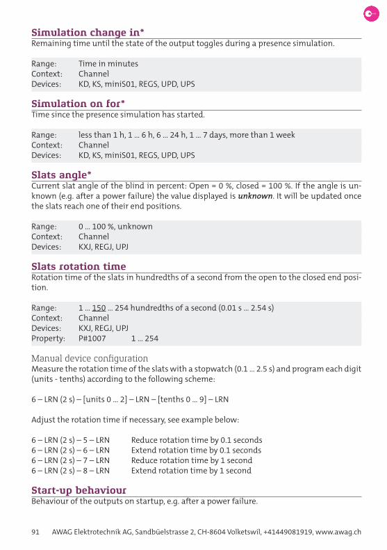
91 AWAG Elektrotechnik AG, Sandbüelstrasse 2, CH-8604 Volketswil, +41449081919, www.awag.ch
Simulation change in*Remaining time until the state of the output toggles during a presence simulation.
Range: Time in minutesContext: ChannelDevices: KD, KS, miniS01, REGS, UPD, UPS
Simulation on for*Time since the presence simulation has started.
Range: less than 1 h, 1 … 6 h, 6 … 24 h, 1 … 7 days, more than 1 weekContext: ChannelDevices: KD, KS, miniS01, REGS, UPD, UPS
Slats angle*Current slat angle of the blind in percent: Open = 0 %, closed = 100 %. If the angle is un-known (e.g. after a power failure) the value displayed is unknown. It will be updated once the slats reach one of their end positions.
Range: 0 … 100 %, unknownContext: ChannelDevices: KXJ, REGJ, UPJ
Slats rotation timeRotation time of the slats in hundredths of a second from the open to the closed end posi-tion.
Range: 1 … 150 … 254 hundredths of a second (0.01 s … 2.54 s)Context: ChannelDevices: KXJ, REGJ, UPJProperty: P#1007 1 … 254
Manual device configurationMeasure the rotation time of the slats with a stopwatch (0.1 … 2.5 s) and program each digit (units - tenths) according to the following scheme:
6 – LRN (2 s) – [units 0 … 2] – LRN – [tenths 0 … 9] – LRN
Adjust the rotation time if necessary, see example below:
6 – LRN (2 s) – 5 – LRN Reduce rotation time by 0.1 seconds 6 – LRN (2 s) – 6 – LRN Extend rotation time by 0.1 seconds6 – LRN (2 s) – 7 – LRN Reduce rotation time by 1 second6 – LRN (2 s) – 8 – LRN Extend rotation time by 1 second
Start-up behaviourBehaviour of the outputs on startup, e.g. after a power failure.

Omnio. Intelligent building automation. 92
Range
Switch position Thermostat actuators Blind actuators Dimmer Switching actua-
tors
0 After a power failure all outputs are switched on. If no temperature signal has been received within 5 minutes, the thermostat actuator switches to frost protection mode. The out-put switches on and off in a 40-minute interval and LRN blinks.
no movement off off
1 go up 100 % channel 1 on
2 go down 25 % channel 2 on
3 - 50 % channel 3 on
4 - 75 % all channels on
5 - pulse 1 sec
7 - - Keep state (UPS10, miniS01)
Context: DeviceDevices: KD, KS, KXJ, miniS01, REGH, REGJ, REGS, UPD, UPH, UPJ, UPSProperty: P#0311 0 … 7 (see table above) switching actuators P#0312 0 … 2 (see table above) blind actuators P#0321 0 … 5 (see table above) dimmer
Manual device configuration13 – LRN (2 s) – [0…7, see table above] – LRN
Staircase light durationTime duration of the staircase light function. See also Function a23: timeR ecoswitch (aw23), Function a24: timeR timeswitch (aw24) and Function a25: timeR comFoRtswitch (aw25). In E-Tool, the switch-on duration is determined by a multiplication of two para-meters, default time = 3 minutes.
Range: 1 s … 3 min … 60 hContext: DeviceDevices: KD, KS, miniS01, REGS, UPD, UPSProperty: P#0323 encoded
Manual device configuration4 – LRN (2 s) – 0 – LRN 10 s4 – LRN (2 s) – 1 – LRN 30 s4 – LRN (2 s) – 2 – LRN 1 min4 – LRN (2 s) – 3 – LRN 2 min4 – LRN (2 s) – 4 – LRN 3 min4 – LRN (2 s) – 5 – LRN 4 min4 – LRN (2 s) – 6 – LRN 5 min4 – LRN (2 s) – 7 – LRN 7 min4 – LRN (2 s) – 8 – LRN 10 min4 – LRN (2 s) – 9 – LRN 15 min4 – LRN (2 s) – 10 – LRN 20 min4 – LRN (2 s) – 11 – LRN 30 min

93 AWAG Elektrotechnik AG, Sandbüelstrasse 2, CH-8604 Volketswil, +41449081919, www.awag.ch
4 – LRN (2 s) – 12 – LRN 45 min4 – LRN (2 s) – 13 – LRN 1 h4 – LRN (2 s) – 14 – LRN 2 h4 – LRN (2 s) – 15 – LRN 3 h
Staircase light prewarning functionIf the prewarning function is enabled, the light will blink once 30 s before the time elapses. It can only be enabled at durations starting from 1 minute. See also device property staiR-case light duRation.
Range: off, onContext: DeviceDevices: KD, KS, miniS01, REGS, UPD, UPSProperty: P#0315 0 (off), 1 (on)
Manual device configuration12 – LRN (2 s) – 0 – LRN Prewarning function enabled12 – LRN (2 s) – 1 – LRN Prewarning function disabled
Stepper (J15), step durationSStep length of slat positioning in hundredths of a second, seen from the perspective of the blind. The delay time of the blind motor, which can be seen in the device parameter motoR delay, is automatically added to the switching time of the relay. See also Function j15: move/stePPeR.
Range: 5 … 10 … 255 hundredths of secondsContext: DeviceDevices: KXJ, REGJ, UPJProperty: P#1062 5 … 255
Manual device configurationNot possible.
Stepper (J15), pause durationPause length of slat positioning in hundredths of a second, seen from the perspective of the blind. The delay time of the blind motor, which can be seen in the device parameter motoR delay, is automatically subtracted from the rest time of the relay. See also Function j15: move/stePPeR.
Range: 5 … 40 … 255 hundredths of secondsContext: DeviceDevices: KXJ, REGJ, UPJProperty: P#1063 5 … 255
Manual device configurationNot possible.

Omnio. Intelligent building automation. 94
Summertime*Indicates summertime. Depending on the sensor type this information is not available.
Range: yes, noContext: DeviceDevices: XFJ
Sun west, south, east*Sunlight intensity from the corresponding direction in kLux.
Range: 0 … 99 kLuxContext: DeviceDevices: XFJ
Telegram repetitionsNumber of telegram repetitions.
Range: 1, 2, 3, 5Context: DeviceDevices: TSTProperty: P#0294 1, 2, 3, 5
Manual device configuration13 – LRN (2 s) – 10 – LRN 113 – LRN (2 s) – 11 – LRN 213 – LRN (2 s) – 12 – LRN 313 – LRN (2 s) – 13 – LRN 5
Temperature*Temperature measured by the room sensor in degrees Celsius.
a) Blind actuator:If the current temperature exceeds the setpoint, in automatic mode the blind will go to the position set in the device property AUTOMATIC END POSITION. If the current temperature drops below the value setpoint – hysteresis, the blind will go to the upper end position, see device property hysteResis* and Function j09: temPeRatuRe sensoR. Since the temperature is evaluated only once per minute, it can lead to delays.
b) Thermostat actuator:If the current temperature exceeds the setpoint, the heating will be switched on. If the cur-rent temperature drops below the value setpoint – hysteresis, the heating will switch off, see device property hysteResis*.
Range: 0 … 40.8 °CContext: ChannelDevices: KXJ, REGH, REGJ, UPH, UPJ, XFJ

95 AWAG Elektrotechnik AG, Sandbüelstrasse 2, CH-8604 Volketswil, +41449081919, www.awag.ch
Temperature control*Operation mode of the blinds. See also Function j09: temPeRatuRe sensoR.
Range: manual, automaticContext: ChannelDevices: KXJ, REGJ, UPJ
Temperature evaluation*Indicates whether the current temperature is above or below the setpoint in automatic mode of the blinds. If the temperature exceeds the setpoint, above setpoint is displayed. Below setpoint is displayed, if the temperature drops below the value setpoint – hysteresis. See also Function j09: temPeRatuRe sensoR.
Range: Above setpoint, below setpoint, unknownContext: ChannelDevices: KXJ, REGJ, UPJ
Temperature monitor*Indicates whether the processor temperature is within the permissible range, see also de-vice property chiP temPeRatuRe*.
Range: OK, ÜbertemperaturContext: DeviceDevices: miniS01
Test blindsThe blinds can be raised and lowered manually for test purposes.
Range: up, down, stopContext: ChannelDevices: KXJ, REGJ, UPJ
Test dimmerThe dimmer can be switched on and off for test purposes.
Range: dim to 100 % dim to 0 % start simulation stop simulationContext: ChannelDevices: KD, UPD
Test switching actuatorThe relay can be switched on and off for test purposes.
Range: switch on relay switch off relay start simulation

Omnio. Intelligent building automation. 96
stop simulationContext: ChannelDevices: KS, miniS01, REGS, UPS
Test thermostat actuatorThe relay can be switched on and off for test purposes.
Range: switch on relay switch off relayContext: ChannelDevices: REGH, UPH
Time*Current time: hour, minute, second. Depending on the sensor type this information is not available.
Range: 00:00:00 … 23:59:59Context: DeviceDevices: XFJ
TST HardwareHardware type of TST-actuator. This property must not be changed!
Range: IN1/IN2 TST230/10 IN/T TST230/12Context: DeviceDevices: TST
Twilight sensor*Daylight in Lux. Depending on the sensor type this information is not available.
Range: 0 … 999 LuxContext: DeviceDevices: XFJ
TypeInternal type identification of the Omnio device in E-Tool. The device type is normally de-tected automatically based on its telegrams, but may need to be set manually. This ensures that the correct properties are displayed in E-Tool
Range: PTM: R101, WS, FG, KSM, TST10, TST12, F01, NBS Sensor: RTF100, RTF160, RTF161, FK, XFJ, PIR, CO2 UP: UPS08, UPS10, UPS12, UPD10, UPJ12, UPH10, UPH12, miniS01, -ES11, -ES16, -ES21, -ES26, -ES31, -ES36, -ES41, -ES46 Kabel: KS10, KD10, KXJ12 REG: REGS04, REGS08, REGJ04, REGH08 Interface: APG03B-RS485, APG03B-RS232, GatewayContext: Device

97 AWAG Elektrotechnik AG, Sandbüelstrasse 2, CH-8604 Volketswil, +41449081919, www.awag.ch
Devices: KD, KS, KXJ, miniS01, REGH, REGJ, REGS, TST, UPD, UPH, UPJ, UPS
UP hardwareHardware type of a flush-mounted actuator. This property must not be changed!
Range: 1-channel latch KS230/10, UPH230/10, UPS230/10 1-channel normal UPS230/08 2-channel KXJ230/12, UPH230/12, UPJ230/12, UPS230/12Context: DeviceDevices: KS, KXJ, UPH, UPJ, UPS
Up time*Time in seconds since last reboot of the device.
Range: Time in secondsContext: DeviceDevices: miniS01
Version*Firmware Version Vyymmdd (year-month-day).
Context: DeviceDevices: KD, KS, KXJ, miniS01, REGH, REGJ, REGS, TST, UPD, UPH, UPJ, UPS, XFJ
Weather data selectionSelection of weather data, which is transmitted via EnOcean radio from the evaluation unit XFJ. The following weather data is available:
Weather (EEP: A5-13-01)Sun (EEP: A5-13-02)Date (EEP: A5-13-03)Time (EEP: A5-13-04)GPS Direction (EEP: A5-13-05)GPS Position (EEP: A5-13-06)
Note: Depending on the type of sensor not all data is available.
Range: weather, sun, date, time, GPS direction, GPS position, weather + sun, weather + sun + date, weather + sun + date + time, Datum + time, weather + sun + date + time + GPS direction, weather + sun + date + time + GPS direction + GPS position, GPS direction + GPS positionContext: DeviceDevices: XFJProperty: P#2034 0 (weather) … 12 (GPS direction + GPS positionn)

Omnio. Intelligent building automation. 98
Weather data transmissionTransmission interval of the weather raw data. In the case of value changes, the data is sent immediately, i.e. also outside the transmission interval.
Range: off, 3 s, 30 s, ~3 min, ~10 min, ~20 minContext: DeviceDevices: XFJProperty: P#2033 0 (off) … 5 (~20 min)
Weather lock-out*Indicates whether the weather lock-out is active. See also Function j11: weatheR station.
Range: on, offContext: ChannelDevices: KXJ, REGJ, UPJ
Weather lock-out delaySwitch-off delay of the weather lock after the end of the alarm. As long as a weather alarm is pending, the weather lock is activated and the blind can’t be operated manually. Only 20 sec-onds after the end of the alarm the weather lock is cancelled. The delay time extends this lockout period, so that the blinds do not constantly go up and down in gusty wind. See also Function j11: weatheR station. The remaining time is displayed in the device property weatheR lock-out delay timeR*.
Range: 0, 5 min.Context: DeviceDevices: KXJ, REGJ, UPJProperty: P#0319 0, 1 (5 minutes)
Manual device configuration12 – LRN (2 s) – 8 – LRN – CLR Disable weather lock-out delay12 – LRN (2 s) – 9 – LRN – CLR Weather lock-out delay 5 min
Weather lock-out delay timer*Indicates the remaining time in seconds of the weather lock-out delay. In case the delay is 5 minutes, the counter displays 255 s during the first 45 seconds and then starts counting back-wards. See also device property weatheR lock-out delay and Function j11: weatheR sta-tion.
Range: 255 … 0 s, counting backwardsContext: DeviceDevices: KXJ, REGJ, UPJ
Window open*Indicates the state of a monitored window.
Range: yes, noContext: Channel

99 AWAG Elektrotechnik AG, Sandbüelstrasse 2, CH-8604 Volketswil, +41449081919, www.awag.ch
Devices: KXJ, REGH, REGJ, UPH, UPJ
Wind speed*Wind speed in m/s.
Range: 0 … 35 m/sContext: DeviceDevices: XFJ

Omnio. Intelligent building automation. 100
© Copyright 2016 - 2021 AWAG Elektrotechnik AG / BZV1.20_210416 (E-Tool V2.07)