reference standards rs-16
TRANSCRIPT

Reference Standard 16
209
REFERENCE STANDARDS RS-16PLUMBING AND GAS PIPING
*LIST OF REFERENCED NATIONAL STANDARDS
ANSI-A21.4 Cement Mortar Lining for Cast Iron Pipe and Fittings ..............................................1964
ANSI-A21.6 Cast-Iron Pipe Centrifugally Cast in Metal Molds for Water or Other Liquids......... 1962
ANSI-A21.8 Cast-Iron Pipe Centrifugally Cast in Sand-Lined Molds for Water or Other Liquids1962
ANSI-A40.4 Air Gaps in Plumbing Systems ......................................…........................................ 1942
ANSI-A40.5 Threaded Cast Iron Pipe for Drainage, Vent, and Waste Services............................. 1943
ANSI-A40.6 Backflow Preventers in Plumbing Systems ............................................................... 1943
ANSI-106.1 Standard and Extra Strength Perforated Clay Pipe, Specifications for ......................1962
ANSI-A106.3 Standard Strength Clay Sewer Pipe, Specifications for .............................................1965**ANSI/AHAM FWD-1 .....................................................................................................................................1992
ANSI/ASME A112.18.1M Finished and Rough Brass Plumbing Fixture Fittings ............................................... 1979
ANSI/ASME A112.19.1M Enameled Cast Iron Plumbing Fixtures ..................................................................... 1987
ANSI A112.19.2M Vitreous China Plumbing Fixtures .............................................................................1982
ANSI/ASME A112.19.3M Stainless Steel Plumbing Fixtures (Designed for Residential Use) .......................... 1987
ANSI/ASME A112.19.4M Porcelain Enameled Formed Steel Plumbing Fixtures .............................................. 1984
ANSI-B2.1 Pipe Threads (Except Dryseal) (Partial Revision of B2.1-1945) ...............................1968
ANSI-B16.3 Malleable-Iron Screwed Fittings, 150 and 300 lb. (Revision and Consolidation of B16.3-1951 and B16.19-1951) .............................................................................................1977
ANSI-B16.4 Cast-Iron Screwed Fittings, 125 and 250 lbs. ............................................................ 1977
ANSI-B16.12 Cast-Iron Screwed Drainage Fittings .........................................................................1976
ANSI-B16.15 Cast-Bronze Screwed Fittings, 125 and 250 lb. (Revision and Consolidation of B16.15-1958 and B16.17-1949) ...........................…………………………………………...1978
ANSI-B16.18 Cast-Bronze Solder-Joint Pressure Fittings ..................... ......................................... 1978
ANSI-B16.22 Wrought Copper and Bronze Solder-Joint Drainage Fittings.....................................1973
ANSI-B16.23 Cast-Bronze Solder-Joint Drainage Fittings .............................................................. 1976
ANSI-B16.24 Bronze Flanges and Flanges Fittings 150 and 300 lb. ............................................... 1979
ANSI B31.2 Fuel Gas Piping ................................................................ .........................................1968
ANSI B31.8 Gas Transmission and Distribution Piping Systems ....... ......................................... 1975
ANSI-B36.1 Welded and Seamless Steel Pipe, Specifications for ................................................. 1966
ANSI-B36.2 Welded Wrought-Iron Pipe, Specifications for ..........................................................1966
ANSI-B36.19 Stainless Steel Pipe .................................................................................................... 1976
ANSI-B36.20 Black and Hot Dipped Zinc-Coated (Galvanized) Welded and Seamless Steel Pipe forOrdinary Uses, Specifications for .............................................................................. 1966
ANSI-C72.1 Household Automatic Electric Storage-Type Water Heaters, Standard for............... 1972
ANSI-G8 Zinc-Coated (Galvanized) Iron or Steel Sheets, Coils, etc. ....................................... 1964
ANSI-H23.1 Seamless Copper Water Tubes, Specification for ............ .........................................1967
ANSI-H23.3 Seamless Copper Tube, Specification for ........................ ......................................... 1965
ANSI-H26.1 Seamless Copper Pipe, Standard Sizes, Specification for.......................................... 1963
Reference Standard 16
210
ANSI-H26.2 Threadless Copper Pipe, Specification for ...................... ......................................... 1963
ANSI-H27.1 Seamless Red Brass Pipe, Standard Sizes, Specification for .....................................1963
ANSI-H36.1 Seamless Brass Tube, Specification for .....................................................................1967
ANSI/NFiPA 50 Standard for Bulk Oxygen Systems at Consumer Sites ............................................1985
ANSI/NFiPA 99 Standard for Health Care Facilities, as modified ....................................................... 1987** ANSI/UL 430 Standard for Waste Disposers ..................... (5th Edition)........................................ 1994
ANSI-Z4.2 Drinking Fountains, Specifications for ...................................................................... 1942
ANSI-Z21.10.1 Gas Water Heaters, Volume I, Automatic Storage Type, Water Heaters with inputs of75,000 BTU per hour or less ..................................................................................... 1981
ANSI Z21.10.3 Gas Water Heaters, Volume III, Circulating Tank, Instantaneous and Large AutomaticStorage Type Water Heaters ...................................................................................... 1981
ANSI-Z21.22 Relief Valves and Automatic Gas Shut-Off Devices for Hot Water Supply Systems,Listing Requirements for ........................................................................................... 1979
ANSI Z223.1/NfiPA No. 54 National Fuel Gas Code including Addenda Z223.1a-1978....................................... 1974
ASME Boiler and Pressure Vessel Code ............................................................................... 1980
API 1104 Standard for Welding Pipelines and Related Facilities ..............................................1977
ASTM-B32 Specification for Solder Metal ................................................................................... 1976
ASTM-B36 Specification for Brass Plate, Sheet, Strip, and Rolled Bar ....................................... 1977
ASTM-B121 Specification for Leaded Brass Plate, Sheet, Strip, and Rolled Bar .......................... 1976
ASTM-B135 Seamless Brass Tube, Specification for .................................................................... 1971a
ASTM-B146 Leaded Yellow Brass Sand Casting for General Purposes, Specification for.............1952
ASTM-B152 Copper Sheet, Strip, Plate, and Rolled Bar, Specification for ................................... 1979
ASTM-B260 Brazing Filler Metal (Tentative), Specification for ....................................................1962T
ASTM-C4 Specification for Clay Drain Tile ...............................................................................1962
ASTM-C13 Specification for Standard Strength Clay Sewer Pipe (Tentative)..............................1964T
ASTM-C14 Specification for Concrete Sewer, Storm Drain, and Culvert Pipe.............................1979
ASTM-C76 Specification for Reinforced Concrete Culvert, Storm Drain, and Sewer Pipe..........1979
ASTM-C200 Specification for Extra Strength Clay Pipe (Tentative) ............................................. 1965T
ASTM-C425 Specification for Vitrified Clay Pipe Joints Using Materials Having Resilient Properties...1977
ASTM-C428 Specification for Asbestos-Cement Non-pressure Sewer Pipe................................... 1978
ASTM-C443 Specification for Joints for Circular Concrete Sewer and Gaskets.............................1978
ASTM-C508 Specification for Asbestos-Cement Perforated Underdrain Pipe............................... 1978a
ASTM-D2513 Thermoplastic Gas Pressure Pipe, Tubing and Fittings ............................................. 1976
ASTM-E84 Method of Test for Surface Burning Characteristics of Building Materials...............1981
AWWA C204 Protective Coating Coal-Tar Enamel ......................................................................... 1951
CISPI Designation 301 Standard Specification for Hubless Cast Iron Soil Pipe and Fittings for Sanitary andStorm Drain, Waste, and Vent Piping Applications ................................................. 1985
CISPI Designation 310 Specification for Cast Iron Soil Pipe Institute’s Approved Coupling for Use inConnection with Hubless Cast Iron Soil Pipe and Fittings for Sanitary and Storm Drain,Waste and Vent Piping Applications ......................................................................... 1985

Reference Standard 16
211
CS-111 Earthenware (Vitreous-Glazed) Plumbing Fixtures ...................................................1943
CS-177 Bituminous-Coated Septic Tanks .............................................................................. 1962
CS-188 Cast-Iron Soil Pipe and Fittings ................................................................................. 1966
CS-270 Non-Metallic Pipe and Fittings Acrylonitrile- Butadiene-Styrene (ABS)..................1965
CS-272 Non-Metallic Pipe and Fittings Polyvinyl Chloride (PVC)........................................ 1965
FS-HH-C536a Compound, Plumbing-Fixture Setting ....................................................................... 1954
FS-HH-G116 Gaskets, Plumbing-Fixture-Setting ............................................................................1936
FS-QQ-L156(1) Lead Caulking ............................................................................................................ 1946
FS-QQ-C40 Caulking: Lead Wool and Lead Pig ..........................................................................1965
FS-QQ-L201d Lead Sheet ..................................................................................................................1961
FS-RR-S726(1) Stills, Water, Portable (Without Heating Device), for U.S.P. "Distilled Water"........1950
FS-SS-P361b Pipe, Clay, Sewer ....................................................................................................... 1962
FS-SS-S169 Sealer, Joint, Sewer, Mineral-Filled, Hot-Pour ..........................................................1954
FS-WW-F406a(1) Flange-Dimensions, Standard: (Classes 125 and 250 Cast-Iron Flanges; Classes 150,250, and 300 Bronze Flanges) (For Land Use) ..........................................................1943
FS-WW-H171C Hangers and Supports, Pipe ....................................................................................... 1964
FS-WW-H191a Heater, Water, Steam-Hot Water Heated (Instantaneous, Steam, Water Converter Type).. 1964
FS-WW-N351a(1) Nipples, Pipe, Threaded ............................................................................................ 1960
FS-WW-U531C Unions, Pipe Steel or Malleable Iron; Thread Connection......................................... 1965
FS-WW-P356 Pipe, Cast-Iron; Drainage, Vent, and Waste (Threaded)............................................ 1936
FS-WW-P360a Pipe, Cast-Iron; Pressure Gas and Water ......................... ......................................... 1959
FS-WW-P401C Pipe and Pipe Fittings, Cast-Iron, Soil ............................. .........................................1963
FS-WW-P406b(1) Pipe Steel (Seamless and Welded) (for Ordinary Use) ..............................................1964
FS-WW-P471a(2) Pipe-Fittings; Bushings, Locknuts, and Plugs; Brass or Bronze, Iron or Steel, andAluminum (Screwed); 125-150 Pounds......................................................................1964
FS-WW-P541b(2) Plumbing Fixtures-Land Use ..................................................................................... 1962
FS-WW-U516 Unions; Brass or Bronze, 250-Pound ........................................................................ 1933
FS-WW-U536(1) Unions; Malleable Iron or Steel, 300-Pound ............................................................. 1933
FS-WW-V51a(2) Valves, Bronze; Angle, Check and Globe, 125- and 150- Pound Screwed and Flanged(for Land Use) ............................................................................................................1954
FS-WW-V54b Valves, Gate, Bronze, 125- and 150-Pound, Screwed and Flanged (for Land Use)...1962
FS-WW-V58(1) Valves, Cast Iron, Gate; 125- and 250-Pound Screwed and Flanged (for Land Use)... 1946
16 NYCRR 255 Transmission and Distribution of Gas ............................. ......................................... 1978
ANSI/IEEE 515 Recommended Practice for the Testing, Design, Installation and Maintenance ofElectrical Resistance Heat Tracing for Industrial Applications .......................... 1983
*Local Law 100-1989; Local Law 29-1989; Local Law 29-1987; Local Law 82-1986; Local Law 30-1982; 1025-88 BCR**Local Law 71-1997
Reference Standard 16
212
TABLE OF CONTENTS
Section Definitions
P101.0 General ProvisionsP101.1 Protection of PipesP101.2 Trenching, Excavation, and BackfillP101.3 SleevesP101.4 RatproofingP101.5 Toilet Facilities for Workmen
P102.0 MaterialsP102.1 General RequirementsP102.2 Standards for Plumbing MaterialsP102.3 Identification MaterialsP102.4 Piping System Materials
P103.0 Joints and ConnectionsP103.1 Types of Joints for Piping MaterialsP103.2 Joints Between Different Piping MaterialsP103.3 Connections Between Drainage Piping and
Certain FixturesP103.4 TightnessP103.5 Waterproofing of OpeningsP103.6 Other Joints
P104.0 Plumbing FixturesP104.1 RequirementsP104.2 Installation of FixturesP104.3 OverflowsP104.4 Water ClosetsP104.5 UrinalsP104.6 Flushing Devices for Water Closets and UrinalsP104.7 LavatoriesP104.8 BathtubsP104.9 ShowersP104.10 SinksP104.11 Dishwashing MachinesP104.12 Automatic Clothes WashersP104.13 Laundry TraysP104.14 Garbage Can WashersP104.15 Fixture StrainersP104.16 Drinking FountainsP104.17 Floor DrainsP104.18 Drains for Drip PipesP104.19 Funnel DrainsP104.20 Special Plumbing Fixtures
P105.0 Traps and CleanoutsP105.1 Fixture TrapsP105.2 Building (House) TrapsP105.3 Drainage Pipe CleanoutsP105.4 Interceptors, Separators, and Neutralizing PitsP105.5 Interceptors, Separators, and Neutralizing Pits
for Specific ServicesP105.6 Venting of Interceptors, Separators, and
Neutralizing PitsP105.7 Accessibility of Interceptors, Separators and
Neutralizing PitsP105.8 Maintenance of Interceptors, Separators and
Neutralizing PitsP105.9 Backwater ValvesP105.10 Industrial Wastes Sampling Manholes
P106.0 Hangers and SupportsP106.1 MaterialP106.2 Attachment to BuildingP106.3 Intervals of Supports
*P106.4 Installation of No-Hub Type Cast Iron SoilPipe, Fittings, and Couplings
*Local Law 100-1989
P107.0 Water Supply and DistributionP107.1 PermitsP107.2 Water ServiceP107.3 MetersP107.4 Check ValvesP107.5 Water Supply Distribution SystemP107.6 Water Supply Control ValvesP107.7 Auxiliary Water SystemsP107.8 Water Supply TanksP107.9 House and Booster PumpsP107.10 Protection of Potable SupplyP107.11 Toxic Materials and SubstancesP107.12 Used PipingP107.13 Prohibited Connections to Fixtures and
EquipmentP107.14 Connections to Mechanical Equipment and
SystemsP107.15 Refrigeration Unit Condensers and Cooling
JacketsP107.16 Air Conditioning and RefrigerationP107.17 Used Water Return ProhibitedP107.18 Protection Against Backflow and Back-
SiphonageP107.19 Approval of DevicesP107.20 Protection of Potable Water Supply OutletsP107.21 Preheating ApparatusP107.22 (Blank)P107.23 Chemical Solution Tanks or ApparatusP107.24 Bedpan WashersP107.25 Laboratory OutletsP107.26 Hot Water Supply SystemP107.27 Disinfection of Potable Water Systems
P108.0 Sanitary Drainage PipingP108.1 PermitsP108.2 Street Sewer ConnectionsP108.3 Abandonment of Existing Building Sewer
Connections
Reference Standard 16
213
P108.4 Building (House Traps)P108.5 Fresh Air InletsP108.6 Drainage Below Sewer LevelP108.7 Sub-Soil DrainageP108.8 Drainage Piping InstallationP108.9 Sanitary Drainage Fixture UnitsP108.10 Sizing the Sanitary Drainage PipingP108.11 Drip Pipes
P109.0 Vent PipingP109.1 Size of VentsP109.2 Protection of Trap SealsP109.3 Vent Stack and Stack VentsP109.4 Vent TerminalsP109.5 Vent Grading and ConnectionsP109.6 Stack VentingP109.7 Common VentsP109.8 Fixture VentsP109.9 Relief VentsP109.10 Suds Pressure Zones VentsP109.11 Permitted Combination Waste and Vent Systems
P110.0 Storm Drainage PipingP110.1 Permits
*P110.2 Disposal of Storm WaterP110.3 Storm Water Drainage to Sanitary Sewer
ProhibitedP110.4 Size of Storm Drains and LeadersP110.5 Values for Continuous FlowP110.6 Controlled Flow Storm Water SystemP110.7 Traps on Storm Drains and LeadersP110.8 Leaders or Storm Water PipingP110.9 Roof Drain StrainersP110.10 Roof Drain Flashings RequiredP110.11 Expansion Joints RequiredP110.12 Sanitary and Storm Sewers
*P110.13 On-Site Disposal*Local Law 103-1989; Local Law 7-1984
P111.0 Indirect Waste PipingP111.1 Indirect Waste RequiredP111.2 Common Indirect WastesP111.3 VentingP111.4 SizingP111.5 Receptors or SumpsP111.6 Condensers and Sumps
P112.0 Special and Miscellaneous Waste PipingP112.1 Industrial WastesP112.2 Chemical WastesP112.3 Flammable Solvents or Oil WastesP112.4 Radioactive Wastes
P113.0 Individual Sewage SystemsP113.1 Information RequiredP113.2 Individual Sewage Disposal Systems
P113.3 Individual Sewage Disposal System (One andTwo-Family Dwellings)
P113.4 Housing Development Sewage Disposal SystemsP113.5 General RequirementsP113.6 LocationP113.7 Septic TanksP113.8 Distribution BoxP113.9 Soil Percolation TestsP113.10 Seepage UnitsP113.11 Subsurface Disposal FieldP113.12 Maintenance
P114.0 Hospital and Institutional PlumbingP114.1 GeneralP114.2 Definitions for Special Hospital Fixtures and
EquipmentP114.3 Requirement for Special Hospital Fixtures and
EquipmentP114.4 Plumbing in Mental HospitalsP114.5 Number of Plumbing FixturesP114.6 Drainage and VentingP114.7 Sterilizer WastesP114.8 Vapor VentsP114.9 Sizing of Sterilizer Vent StacksP114.10 Water SupplyP114.11 Vacuum SystemsP114.12 Oxygen and Nitrous Oxide Systems
P115.0 Gas PipingP115.1 General Requirements for Gas PipingP115.2 Gas Service Piping ConnectionsP115.3 Gas Regulator and Gas Regulator Vent OutletsP115.4 Outside Gas Cut-OffP115.5 Gas Meter LocationP115.6 Gas Piping Materials and FittingsP115.7 Installation of Gas PipingP115.8 Gas Piping Sizes
P116.0 Swimming Pools and Display Pools or FountainsP116.1 Swimming PoolsP116.2 Display Pools and Fountains
LIST OF TABLESIndex Table No.RS 16-1 Standards for Plumbing MaterialsRS 16-2 DeletedRS 16-3 Caulking FerrulesRS 16-4 Soldering BushingsRS 16-5 Minimum Number of Plumbing Fixtures
RequiredRS 16-6 Minimum Size of Fixture Traps for Various
Types of Plumbing FixturesRS 16-7 Minimum Rate of Flow and Minimum Required
Pressure During Flow for Sizing IndividualBranch Supplies for Plumbing Fixtures
RS 16-8 Size of Overflows for Gravity and Suction
Reference Standard 16
214
TanksRS 16-9 Size of Weirs for Gravity and Suction TanksRS 16-10 Suction Tank SizesRS 16-11 Cross-Connection Where Protective Devices
are Required and Critical Level (C-L) Settingfor Vacuum Breakers
RS 16-12 Sanitary Drainage Fixture Unit ValvesRS 16-13 Maximum Permissible Loads for Sanitary
Drainage Piping (in terms of fixture units)RS 16-14 Size of Vent Stacks and Branch VentsRS 16-15 DeletedRS 16-16 DeletedRS 16-17 Size of Horizontal Storm DrainsRS 16-18 Size of Vertical LeadersRS 16-19 Size of Roof Gutters**Local Law 85-1973RS 16-20 Fixture Unit-Drainage Square Footage
EquivalentRS 16-21 Minimum Distances Between Sewage
System Components and BetweenComponents and EncumbrancesRS 16-22 Minimum Capacity of Septic TanksRS 16-23A Design Data for Absorptive Capacity of
Disposal Field and Seepage PitsRS 16-23BDesign Data for Absorptive Capacity of
Disposal Field and Seepage PitsRS 16-24 Limiting Dimensions of Disposal Field
ComponentsRS 16-25 Minimum Number of Fixtures for Hospitals
and InstitutionsRS 16-26 Stack Sizes for Bedpan Steamers and
Boiling Type Sterilizers, and of ConnectionsPermitted
RS 16-27 Stack Sizes for Pressure Sterilizers andNumber of Connections Permitted
RS 16-28 Fixture Water Supply Protection
LIST OF ILLUSTRATIONS
Figure No.RS 16-1 Methods of Connecting Overflow from Gravity
House and Suction Water Supply TanksRS 16-2 Sizing of Branch Vent Piping and Drop Vents
to First Floor, Basement and Cellar FixturesRS 16-3 DeletedRS 16-4 Vent ArrangementsRS 16-5 DeletedRS 16-6 Offsets in Buildings Five Stories or MoreRS 16-7 Relief Vents for Stack of More than Ten Branch
IntervalsRS 16-8 Suds Pressure ZonesRS 16-9 Combination Waste and Vent Oil Waste
Drainage**RS 16-9A Yard Drain With Sump**RS 16-9B Detail of Dry Well With Sand Column
RS 16-10 Acid Drainage for Buildings Four Stories or Less
RS 16-11 Acid Drainage for Buildings Over FourStories
*RS 16-12A Typical Concrete Septic Tank*RS 16-12B Typical Metal Septic Tank*RS 16-13A Absorption Type System*RS 16-13B Absorption Type
*Local Law 85-1973**Local Law 103-1989
Section P100.0 DefinitionsThe following definitions shall be used in the applicationof this reference standard.
AIR-BREAK (DRAINAGE SYSTEM).—Apiping arrangement in which a drain from a fixture,appliance, or device discharges through an air breakinto a fixture, receptacle, or interceptor at a point abovethe flood level rim of the receptacle.
AIR GAP (WATER DISTRIBUTION SYSTEM).—The unobstructed vertical distance through the freeatmosphere between the lowest opening from any pipeor faucet supplying water to a tank, plumbing fixture, orother device and the flood level rim of the receptacle.
BACKFLOW.—The flow of water or otherliquids, mixtures, or substances into the distributingpipes of a potable supply of water from any source orsources other than its intended source. (See back-siphonage.)
BACK-SIPHONAGE.—The flowing back ofused, contaminated, or polluted water from a plumbingfixture or vessel into a water-supply system due to anegative pressure in such pipe. (See backflow.)
BATTERY OF FIXTURES.—Any group oftwo or more similar adjacent fixtures that discharge intoa common horizontal waste or soil branch.
BRANCH.—That part of a piping systemother than a main, riser, or stack that extends to fixtureson two or less consecutive floors.
BRANCH INTERVAL.—A distance along asoil or waste stack corresponding in general to a storyheight, but in no case less than 8 ft. within which thehorizontal branches from one floor or story of abuilding are connected to the stack.
BRANCH VENT.—A vent connecting one ormore individual vents with a vent stack or stack vent.
BUILDING HOUSE DRAIN.—That part ofthe lowest piping of a drainage system that receives thedischarge from the soil, waste, and other drainage pipesof the building and conveys it to the building housesewer by gravity; the building house drain shall beconsidered to extend 5 ft. outside the building wall.
BUILDING HOUSE DRAIN (COMBINED).—A building house drain that conveys both storm waterand sewage or other drainage.
BUILDING HOUSE DRAIN (SANITARY).—A building house drain carrying sewage only.
BUILDING GRAVITY DRAINAGE SYSTEM.—A drainage system that drains by gravity into the
Reference Standard 16
215
building house sewer.BUILDING HOUSE SEWER.—That part of
the horizontal piping of a drainage system that extendsfrom the end of the building house drain and thatreceives the discharge of the building house drain andconveys it to a public sewer, private sewer, individualsewage-disposal system or other point of disposal.
BUILDING HOUSE SEWER (COMBINED).—A building house sewer that conveys both sewage andstorm water and other clear water wastes.
BUILDING HOUSE SEWER (SANITARY).—A building house sewer carrying sewage only.
BUILDING HOUSE STORM DRAIN.—Thatpart of the lowest piping of a storm drainage systemthat receives clear water drainage from leaders, surfacerun-off, ground water, subsurface water, condensate,cooling water or other similar storm or clear waterdrainage pipes inside of the walls of the building andconveys to it to the building house storm sewer bygravity; the building house storm drain shall beconsidered to extend 5 ft. outside of the building wall.
BUILDING HOUSE STORM SEWER.—That part of the horizontal piping of the storm drainagesystem that extends from the building house storm drainto the public storm sewer, combined sewer, or otherpoint of disposal.
BUILDING SUB-HOUSE DRAIN.—Theportion of a house drainage system that conveys thedrainage from the lower portion of the building to anejector pit or sump pit from which it is pumped into thebuilding house sewer.
BUILDING HOUSE TRAP.—A trap, orassembly of fittings, installed in the building housedrain to prevent circulation of air between the housedrainage system and the building house sewer.
CESSPOOL.—A covered excavation in theground that receives the discharge of domestic sewageor other organic wastes from a drainage system, sodesigned as to retain the organic matter and solids, butpermitting the liquid to seep through the bottom and sides.
COMBINATION FIXTURE.—A fixturecombining one sink and tray or two- or three-compartment sink or tray in one unit.
COMBINATION WASTE AND VENTSYSTEM.—A specially designed system of wastepiping embodying the horizontal wet venting of one ormore sinks or floor drains by means of a common wasteand vent pipe.
COMMON VENT.—A vent connecting atthe junction of two fixture drains and serving as a ventfor both fixtures and drains.
CONTINUOUS VENT.—A vertical vent thatis a continuation of the drain to which it connects.
CONTINUOUS WASTE.—A drain from twoor three fixtures connected to a single trap.
CROSS-CONNECTION.—A physical connection
or arrangement between two otherwise separate pipingsystems, one of which contains potable water and theother with either water of unknown or questionablesafety or steam, gases, or chemicals whereby there canbe a flow from one system to another.
DEAD END.—A branch leading from a soil,waste, or vent pipe, building house drain, or buildinghouse sewer, which is terminated to a developeddistance of 2 ft. or more by means of a plug or otherclosed fitting.
DEVELOPED LENGTH.—The length along thecenter line of pipe and fittings, both horizontal and vertical.
DIAMETER.—Unless otherwise specificallystated, the term "diameter" is the nominal diameter asdesignated commercially.
DOMESTIC SEWAGE.—The water-bornewastes derived from ordinary living processes.
DRAIN.—Any pipe that carries waste wateror water-borne wastes in a building drainage system.
DRAINAGE SYSTEM.—Includes all thepiping within public or private premises, which conveyssewage, rain water, or other liquid wastes to a legalpoint of disposal, but does not include the mains of apublic sewer system or private or public sewage-treatment or disposal plant.
DRY WELL.—See leaching well or pit.DUAL VENT.—See common vent.EFFECTIVE OPENING.—The minimum
cross-sectional area at the point of water-discharge,measured or expressed in terms: (1) diameter of acircle; (2) if the opening is not circular, the diameter ora circle of equivalent cross-sectional area.
EXISTING WORK.—A plumbing system orany part thereof installed prior to the effective date ofthis code.
FIRE LINE.—A system of pipes and equipmentused exclusively to supply water for extinguishing fires.
FIXTURE.—See plumbing fixture.FIXTURE BRANCH.—A water supply pipe
connecting one or more fixtures to a main water supplyheader or riser.
FIXTURE DRAIN.—The drain from the trapof a fixture to the junction of that drain with any otherdrain pipe.
FIXTURE SUPPLY.—A water-supply pipeconnecting the fixture with the fixture branch.
FLOOD LEVEL RIM.—The top edge or rimof a receptacle from which water can overflow regardlessof the location of any overflow piping from the receptacle.
FLOODED.—A fixture is flooded when theliquid therein rises to the flood level rim.
FLUSH VALVE.—A device located at thebottom of the tank for the purpose of flushing waterclosets and similar fixtures.
FLUSHOMETER VALVE.—A device thatdischarges a predetermined quantity of water to fixtures

Reference Standard 16
216
for flushing purposes and is actuated by direct water pressure.FROSTPROOF WATER CLOSET.—A
hopper that has no water in the bowl and has the trapand the control valve for its water supply installedbelow the frost line.
GAS DISTRIBUTION PIPING.—All pipingfrom the house wide of the gas meter piping that distributesthe gas supplied by a public utility to all fixtures andapparatus used for illumination or fuel in any building
GAS METER PIPING.—The piping from theshut-off valve inside the building to the outlet of the meter.
GAS SERVICE PIPING.—The supply pipefrom the street main through the building wall andincluding the stopcock or shut-off valve inside the building.
INDIRECT WASTE PIPE.—A drain pipeused to convey liquid wastes that does not connectdirectly with the drainage system, but which dischargesinto the house drainage system through an air break intoa trap, fixture, receptacle, or interceptor.
INDUSTRIAL WASTE.—A liquid, gaseousor solid substance, or a combination thereof resultingfrom any process of industry, manufacturing, trade orbusiness or from the development or recovery of anynatural resource.
INTERCEPTOR.—A device designed andinstalled so as to separate and retain deleterious, hazardous,or undesirable matter from normal wastes and permitnormal sewage or liquid wastes to discharge into thedisposal terminal by gravity.
LEACHING WELL OR PIT.—A coveredpit constructed so as to permit the liquid contents toseep into the ground.
LEADER.—A vertical drainage pipe forconveying storm water from roof or gutter drains to thebuilding storm drain, building house drain (combined).or other means of disposal. The leader shall include thehorizontal pipe to a single roof drain or gutter drain.
LIQUID WASTE.—The discharge from anyfixture, appliance, or appurtenance, in connection witha plumbing system that does not receive fecal matter.
LOAD FACTOR.—The percentage of thetotal connected fixture unit flow rate that is likely tooccur at any point in the drainage system.
LOCAL VENTILATING PIPE.—A pipe onthe fixture side of the trap through which vapor or foulair is removed from a room or fixture.
NORMAL SEWAGE.—Normal sewagemeans "normal sewage" as defined in the rules andregulations of the Department of Public Works.
PITCH.—See grade.pH VALUE.—An arbitrary symbol adopted to
express the degree of acidity or alkalinity of a solution.It is the logarithm of the reciprocal of the hydrogenionconcentration, in gram mols per liter at 71.6oF. A pH of7.0 represents a neutral solution, lower values representacidity, higher values alkalinity.
PIPING.—As used in this reference standard,piping shall include fittings, valves, and other accessoriesor appurtenances required to make a complete installation.
PLUMBING.—The practice, materials, andfixtures used in the installation, maintenance, extension,repair, replacement, relocation and alteration of all piping,fixtures, appliances, and appurtenances in connection withany of the following, sanitary drainage or storm drainagefacilities, the venting system, and public or private watersupply systems, within or adjacent to any building; also, thepractice and materials used in the installation, maintenance,extension, repair, replacement, relocation or alteration ofstorm water, liquid-waste, or sewerage, and water-supplysystems of any premises in their connection with anypoint of public disposal or other acceptable terminal.
PLUMBING FIXTURES.—Installed receptacles,devices, or appliances that are supplied with water orthat receive or discharge liquids or liquid-borne wastes.
PLUMBING SYSTEM.—Includes the water-supply and distribution pipes; plumbing fixtures andtraps; soil, waste, and vent pipe; building house drainsand building house sewers including their respectiveconnections, devices, and appurtenances within theproperty lines of the premises, and water-treating orwater-using equipment.
POOL.—A water receptacle used forswimming or as a plunge or other bath, designed toaccommodate more than one bather at a time. Also areceptacle used for decorative purposes.
POTABLE WATER.—Water free fromimpurities present in amounts sufficient to cause disease orharmful physiological effects. Its bacteriological andchemical quality shall conform to the requirements ofthe department of health of the City of New York.
PRIVATE OR PRIVATE USE.—In theclassification of plumbing fixtures, "private" applies tofixtures in residences and apartments and to fixtures inbathrooms of hotels and similar installations where thefixtures are intended for the use of a family or an individual.
PRIVATE SEWER.—A sewer privatelyowned and controlled by public authority only to theextent provided by law.
PUBLIC OR PUBLIC USE.—In theclassification of plumbing fixtures, "public" applies tofixtures in general toilet rooms of schools, gymnasiums,hotels, railroad stations, public buildings, bars, comfortstations, and other installations (whether pay or free)where fixtures are installed so that their use is similarlyunrestricted.
PUBLIC SEWER.—A common sewer directlycontrolled by public authority.
RELIEF VENT.—A vent installed so as topermit additional circulation of air between thedrainage and vent systems where the drainage systemmight otherwise be air bound.
RIM.—An unobstructed open edge of a fixture.
Reference Standard 16
217
RISER.—A water-supply pipe that extendsvertically one full story or more to convey water tobranches or fixtures.
ROOF DRAIN.—A drain installed to receivewater collecting on the surface of a roof and todischarge it into the leader (downspout).
ROUGHING-IN.—The installation of all partsof the plumbing system that can be completed prior to theinstallation of fixtures. This includes drainage, water-supply, and vent piping, and the necessary fixture supports.
SANITARY SEWAGE.—See domestic sewage.SANITARY SEWER.—A pipe that carries
sewage and excludes storm, surface and ground water.SEEPAGE PITS OR WELLS.—A covered
pit with open jointed or perforated lining into which theseptic tank effluent is discharged. The liquid portion ofthe sewage seeps into the surrounding porous soil. Theremaining solids or sludge is retained in the pit.
SEPARATOR.—See interceptor.SEPTIC TANK.—A watertight receptacle
that receives the discharge of a drainage system or partthereof, and is designed and constructed so as toseparate solids from the liquid, digest organic matterduring a period of detention, and allow the liquids todischarge into the soil outside of the tank through asystem of open-joint or perforated piping, or seepage pit.
SEWAGE.—Any liquid waste containinganimal or vegetable matter in suspension or solution,and may include liquids containing chemicals in solution.
SEWAGE DISPOSAL SYSTEM.—Asystem for the disposal of domestic sewage by means ofa septic tank, cesspool, or mechanical treatment, alldesigned for use apart from a public sewer to serve asingle establishment, building, or development.
SEWAGE EJECTOR.—A mechanicaldevice used to pump or eject sewage.
SEWAGE EJECTOR PIT.—A tank or pitthat receives sewage located below the normal grade ofthe gravity system and that must be emptied bymechanical means.
SIDE VENT.—A vent connecting to the drainpipe through a fitting at an angle not greater than 45degrees to the vertical.
SLOPE.—See grade.SOIL PIPE.—A pipe that conveys sewage
containing fecal matter.SPECIAL WASTE.—Waste which requires
special treatment before entry into the normal plumbingsystem.
STACK.—A general term for any vertical lineof soil, waste, vent, or inside leader piping. This doesnot include vertical fixture and vent branches that donot extend through the roof or that pass through notmore than two stories before being reconnected to thevent stack or stack vent.
STACK VENT (SOMETIMES CALLED A
WASTE VENT OR SOIL VENT).—The extension of asoil or waste stack above the highest horizontal drainconnected to the stack.
STACK VENTING.—A method of venting afixture or fixtures through the soil waste stack.
STORM DRAIN.—See building storm drain.STORM SEWER.—A sewer used for conveying
rain water, surface water, condensate, cooling water, orsimilar clear liquid wastes.
SUB-HOUSE DRAIN.—See building sub-house drain.
SUB-SURFACE DISPOSAL FIELD.—Asystem of open jointed tile or perforated pipes or drainsthrough which storm water or the sewage effluent froma septic tank is distributed beneath the surface of theground for absorption into the soil, as well as evaporationinto the air during favorable weather conditions.
SUB-SOIL DRAIN.—A drain that receivesonly sub-surface or seepage water and conveys it to aplace of disposal.
SUMP PIT.—A tank or pit that receives clearliquid wastes, that do not contain organic materials orcompounds subject to decomposition, located below thenormal grade of the gravity system and which must beemptied by mechanical means.
SUMP PUMP.—A mechanical device used toeject or pump the liquid waste from a sump pit into thegravity drainage system.
SUPPORTS.—Devices for supporting andsecuring pipe, fixtures, and equipment.
SWIMMING POOL.—Any structure, basin,chamber or tank containing water for swimming,diving, or recreational bathing and having a depth of 2ft. or more at any one point.
TRAP.-A fitting or device with a smoothinterior passage, the inside diameter of which is equalto the inlet pipe diameter, and which provides a liquidseal of at least 2 in.
TRAP SEAL.-The maximum vertical depth ofliquid that a trap will retain, measured between thecrown weir and the top of the dip of the trap. Seal 2 in.in normal traps and 3 in. or more for deep seal traps.
VACUUM BREAKER.—A device used toprevent backflow by siphonic action.
VENT PIPE.—See vent system.VENT STACK.—A vertical vent pipe installed
primarily for the purpose of providing circulation of airto and from any part of the drainage system.
VENT SYSTEM.—A pipe or pipes installedto provide a flow or air to or from a drainage system orto provide a circulation of air within such system toprotect trap seals from siphonage and back pressure.
VERTICAL PIPE.—Any pipe or fitting thatis installed in a vertical position or that makes an angleof not more than 45 degrees with the vertical.
WASTE PIPE.—A pipe that conveys only
Reference Standard 16
218
liquid waste, free of fecal matter.WATER-DISTRIBUTION PIPING.—In a
building or premises, piping that conveys water fromthe water service pipe to the plumbing fixtures andother water outlets.
WATER (STREET) MAIN.—A water-supplypipe for public or community use controlled by public authority.
WATER OUTLET.—As used in connectionwith the water-distributing system, is the dischargeopening for the water to a fixture; to atmosphericpressure (except into an open tank which is part of thewater-supply system); to a boiler or heating system; toany water-operated device or equipment requiring waterto operate, but not a part of the plumbing system.
WATER SERVICE PIPING.—That portionof the water supply system extending from the publicstreet water main to the house control valve inside thebuilding to a point where the supply is fully metered.
WATER SUPPLY SYSTEM.—Consists ofthe water-service pipe, the water-distribution pipes, andthe necessary connecting pipes, fittings, control valves,and all appurtenances used for conveying water.
YOKE VENT.—A pipe connecting upwardfrom a soil or waste stack to a vent stack for thepurpose of preventing pressure changes in the stack.
Section P101.0 General ProvisionsP101.1 Protection of Pipes.-
(a) Breakage.—Pipe passing under or through wallsshall be protected from breakage. Any plumbing pipepassing under a footing or through a foundation wallshall be protected from carrying any weight of thestructure by an arch or lintel constructed above the pipeby an iron-pipe sleeve built into the masonry wall andgreater in size than the pipe passing through the wall, orby an equivalent method of protection.(b) Corrosion.—Pipe subject to external corrosion bypassing through or under corrosive material shall beprotected against external corrosion by protectivecoating, wrapping, or other equivalent means that willresist such corrosion.
P101.2 Trenching, Excavation, and Backfill.-(a) Material for backfill.—Trenches shall bebackfilled by hand and tamped, in 6 in. layers, for 1 ft.above the crown of the pipe. Loose earth, free fromfrozen earth chunks or other material that may break thepipe, shall be used to provide firm bedding around thepipe.(b) Trenching methods.-(1) Trenches shall be excavated to a width sufficient topermit workmen to properly install the pipe. The bottomof the pipe trench shall be constructed so that the pipebetween joints will have solid bearing along its entirelength. Bell holes shall be provided at points where the
pipe is joined together to insure uniform bearing alongthe length of the pipe. In rock excavation the materialshall be removed 3 in. to 6 in. below the grade line ofthe trench and then backfilled and tamped to grade withsand to provide a uniform firm foundation for the pipe.If soil materials of class 11-65 or poorer are encounteredthe pipe shall be supported in accordance with the applicableprovisions of the building code for structural work.(2) Where open trenches are impractical, pipe may beinstalled by driving or tunneling methods acceptable tothe commissioner. Where driving or tunneling methodsare employed, special care shall be exercised to protectthe pipe from breakage and against earth settling orcaving. Pipe may be installed in a previously drivenconduit slightly larger than the pipe. Earth tunnels witha length not exceeding the depth of the trench may beemployed, providing adequate supporting structures areprovided to prevent future settling or caving.(3) Permits for sidewalk and street openings shall beobtained from the department of highways.
P101.3 Sleeves.-(a) The annular space between sleeves and pipethrough foundation or exterior building walls shall befilled or partly caulked with polysulphide compound,lead, or other equivalent waterproofing material.(b) Where pipes and sleeves pass through constructionrequired to have a fire-resistance rating, they shall complywith the applicable requirements of the building code.
P101.4 Ratproofing.—In an apartment or indwelling units, and in buildings or building areas usedfor the storage or preparation of food, the openings inwalls, floors, or ceilings for the passage of pipes shallbe closed and protected by metal collars securelyfastened to the structure.
P101.5 Toilet Facilities for Workmen.—Thesite upon which any building, except a one- or two-family dwelling, is being constructed shall be providedwith toilet facilities for use of workmen as specified inTable RS 16-5.
Section P102.0 MaterialsP102.1 General Requirements.-
(a) Materials required.—All materials used in theconstruction of any plumbing system, fixtures, orequipment shall be as required by this reference standard.(b) Installation.—All materials installed in plumbingsystems shall be handled and installed so as to avoiddamage to the material.
P102.2 Standards for Plumbing Materials.-(a) Materials.—Materials shall conform to one of thestandards cited in Table RS 16-1. Equivalent materialsnot listed in Table RS 16-1 may be used provided theyare approved.

Reference Standard 16
*TABLE RS 16-1 STANDARDS FOR PLUMBING MATERIALSa Materials ANSI Other Ferrous Pipe and Fittings- Cast iron soil pipe and fittings coupling... None CISPI 310-1985 Hubless cast iron soil pipe .................. None CISPI 301-1985 Cast iron soil pipe and fittings, extra heavy and service weights ...… None CS188-66 Cast iron water pipe .........................… A21.6-1962 A21.8-1962 Cast iron pipe, drainage, vent and waste… None FS-WW-P356-1936 Cast iron pipe, pressure (50 lb.) gas and water ……………………… None FS-WW-P360a-1959 Cast iron (threaded) pipe .................... A40.5-1943 Cast iron (threaded) fittings ................ B16.4-1963 Cast iron drainage fittings ................... B16.12-1965 Galvanized pipe and fitting ................ None FS-WW-P406(1) 1945 Malleable iron fittings (threaded) 150 lbs. ............................................ B16.3-1963 300 lbs. ............................................ B16.3-1963 Steel pipe, seamless and welded, black and zinc coated (not intended for close coiling) ….... B36.20-1966 Steel pipe, seamless and welded, black and zinc coated (suitable for close coiling) ……....... B36.1-1966 Stainless steel pipe ............................. B36.19-1965 Union, malleable iron or steel ............. None *FS-WW-O531a-1957 FS-WW-U536(1)-1953 Wrought-iron pipe .............................. B36.2-1966 Valves, cast iron, gate 125 and 250 lb. threaded and flanged ............ None FS-WW-V58(1)-1946 Pipe fittings, bronze and ferrous (bushings, plugs and locknuts), threaded ..………………………...... None FS-WW-P471(1)-1946 Nipples, pipe threaded ....................... None FS-WW-N351a-1956 Non-Ferrous Pipe and Fittings- Finished and rough brass plumbing fixture fittings .................... None ASME A112.18.1M-79 Brass tube ........................................... H36.1-1967 Brass pipe .......................................... H27.1-1963 Brass or bronze flanges and flanged fittings, 150 and 300 lb. ...... B16.24-1962 Brass or bronze screwed fittings, 125 lb and 250 lb. .……………....... B16.15-1964 Cast-bronze solder joint pressure fittings …………………………..... B16.18-1963 Cast-brass solder joint drainage fittings .………………………........ B16.23-1960 Copper pipe ........................................ H26.1-1963 Copper pipe, threadless ...................... H26.2-1963 Seamless copper tube ......................... H23.3-1965 Copper water tube, type K, L ............ H23.1-1967 Wrought copper and wrought bronze solder joint fittings .....…...... H16.22-1963 *As enacted but “FS-WW-U531a-1957” probably intended.
revision: July 1, 2008 219
Reference Standard 16
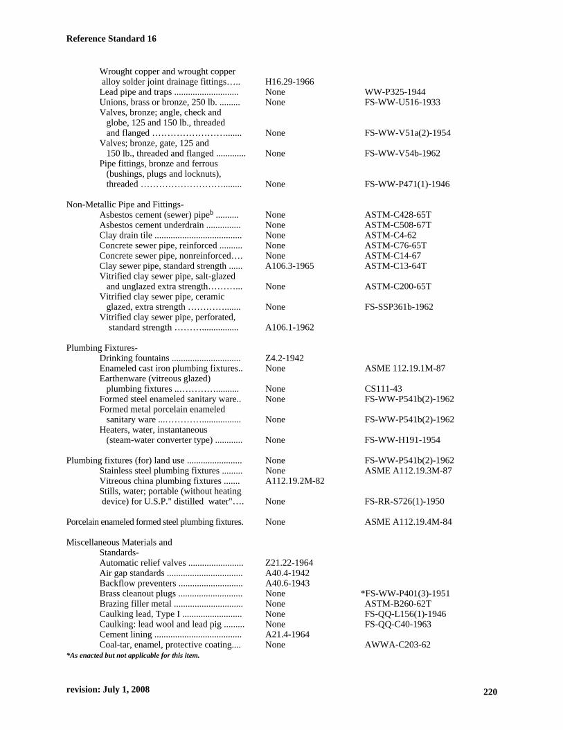
Wrought copper and wrought copper alloy solder joint drainage fittings….. H16.29-1966 Lead pipe and traps ............................ None WW-P325-1944 Unions, brass or bronze, 250 lb. ......... None FS-WW-U516-1933 Valves, bronze; angle, check and globe, 125 and 150 lb., threaded and flanged ……………………....... None FS-WW-V51a(2)-1954 Valves; bronze, gate, 125 and 150 lb., threaded and flanged ............. None FS-WW-V54b-1962 Pipe fittings, bronze and ferrous (bushings, plugs and locknuts), threaded ………………………........ None FS-WW-P471(1)-1946 Non-Metallic Pipe and Fittings- Asbestos cement (sewer) pipeb .......... None ASTM-C428-65T Asbestos cement underdrain ............... None ASTM-C508-67T Clay drain tile ...................................... None ASTM-C4-62 Concrete sewer pipe, reinforced .......... None ASTM-C76-65T Concrete sewer pipe, nonreinforced…. None ASTM-C14-67 Clay sewer pipe, standard strength ...... A106.3-1965 ASTM-C13-64T Vitrified clay sewer pipe, salt-glazed and unglazed extra strength………... None ASTM-C200-65T Vitrified clay sewer pipe, ceramic glazed, extra strength …………....... None FS-SSP361b-1962 Vitrified clay sewer pipe, perforated, standard strength ………................ A106.1-1962 Plumbing Fixtures- Drinking fountains .............................. Z4.2-1942 Enameled cast iron plumbing fixtures.. None ASME 112.19.1M-87 Earthenware (vitreous glazed) plumbing fixtures ..………….......... None CS111-43 Formed steel enameled sanitary ware.. None FS-WW-P541b(2)-1962 Formed metal porcelain enameled sanitary ware ...…………................. None FS-WW-P541b(2)-1962 Heaters, water, instantaneous (steam-water converter type) ............ None FS-WW-H191-1954 Plumbing fixtures (for) land use ........................ None FS-WW-P541b(2)-1962 Stainless steel plumbing fixtures ......... None ASME A112.19.3M-87 Vitreous china plumbing fixtures ....... A112.19.2M-82 Stills, water; portable (without heating device) for U.S.P." distilled water"…. None FS-RR-S726(1)-1950 Porcelain enameled formed steel plumbing fixtures. None ASME A112.19.4M-84 Miscellaneous Materials and Standards- Automatic relief valves ........................ Z21.22-1964 Air gap standards ................................. A40.4-1942 Backflow preventers ............................ A40.6-1943 Brass cleanout plugs ............................ None *FS-WW-P401(3)-1951 Brazing filler metal .............................. None ASTM-B260-62T Caulking lead, Type I .......................... None FS-QQ-L156(1)-1946 Caulking: lead wool and lead pig ......... None FS-QQ-C40-1963 Cement lining ...................................... A21.4-1964 Coal-tar, enamel, protective coating.... None AWWA-C203-62 *As enacted but not applicable for this item.
revision: July 1, 2008 220
Reference Standard 16
221
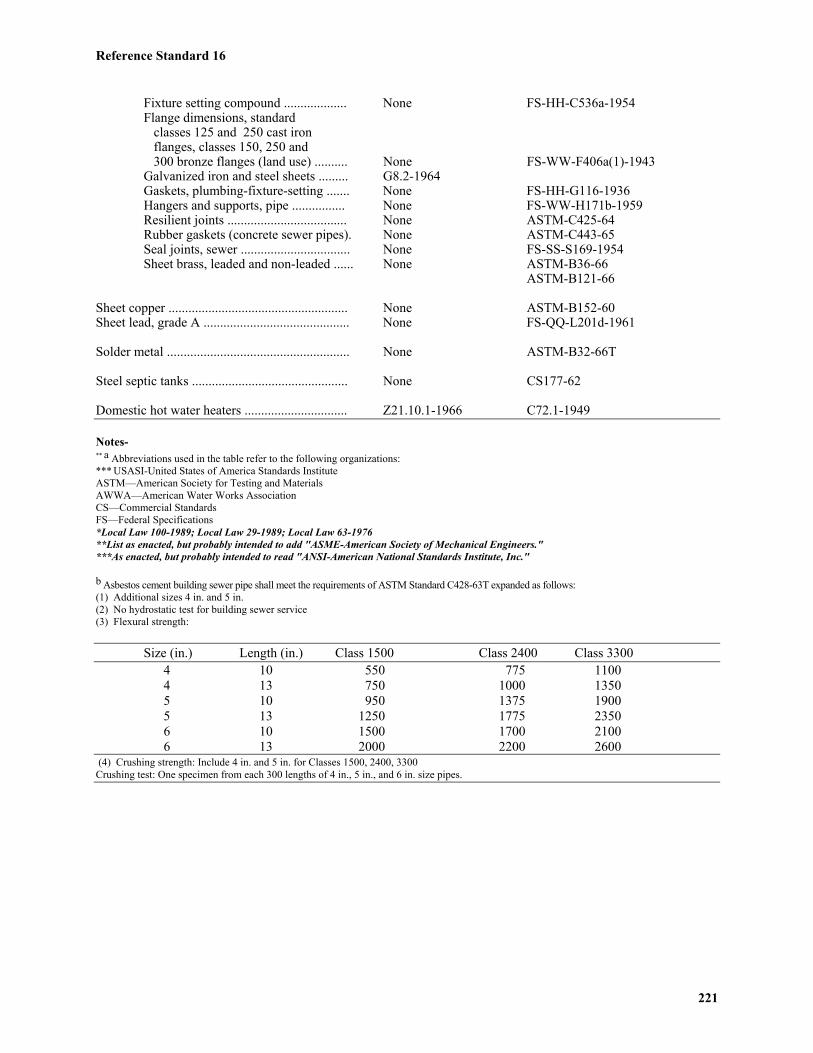
Fixture setting compound ................... None FS-HH-C536a-1954Flange dimensions, standard classes 125 and 250 cast iron flanges, classes 150, 250 and 300 bronze flanges (land use) .......... None FS-WW-F406a(1)-1943Galvanized iron and steel sheets ......... G8.2-1964Gaskets, plumbing-fixture-setting ....... None FS-HH-G116-1936Hangers and supports, pipe ................ None FS-WW-H171b-1959Resilient joints .................................... None ASTM-C425-64Rubber gaskets (concrete sewer pipes). None ASTM-C443-65Seal joints, sewer ................................. None FS-SS-S169-1954Sheet brass, leaded and non-leaded ...... None ASTM-B36-66
ASTM-B121-66
Sheet copper ...................................................... None ASTM-B152-60Sheet lead, grade A ............................................ None FS-QQ-L201d-1961
Solder metal ....................................................... None ASTM-B32-66T
Steel septic tanks ............................................... None CS177-62
Domestic hot water heaters ............................... Z21.10.1-1966 C72.1-1949
Notes-** a Abbreviations used in the table refer to the following organizations:*** USASI-United States of America Standards InstituteASTM—American Society for Testing and MaterialsAWWA—American Water Works AssociationCS—Commercial StandardsFS—Federal Specifications*Local Law 100-1989; Local Law 29-1989; Local Law 63-1976**List as enacted, but probably intended to add "ASME-American Society of Mechanical Engineers."***As enacted, but probably intended to read "ANSI-American National Standards Institute, Inc."
b Asbestos cement building sewer pipe shall meet the requirements of ASTM Standard C428-63T expanded as follows:(1) Additional sizes 4 in. and 5 in.(2) No hydrostatic test for building sewer service(3) Flexural strength:
Size (in.) Length (in.) Class 1500 Class 2400 Class 3300 4 10 550 775 1100 4 13 750 1000 1350 5 10 950 1375 1900 5 13 1250 1775 2350 6 10 1500 1700 2100 6 13 2000 2200 2600
(4) Crushing strength: Include 4 in. and 5 in. for Classes 1500, 2400, 3300Crushing test: One specimen from each 300 lengths of 4 in., 5 in., and 6 in. size pipes.

Reference Standard 16
222
†(b) Plastic piping and fittings.-Plastic piping andfittings may be used only in residential buildings ofthree stories or less in height, except that corrugatedpolyethylene piping with a diameter of twelve inches ormore and plastic fittings may be used in connectionwith any type of building for underground yard drainageand storm water piping when used outside of thefoundation walls of the building and not connecting toany piping system from the interior of the building andshall be approved. Plastic drain, waste and vent pipeand fittings used inside of residential buildings of threestories or less in height shall be required to conformwith ASTM Standard D2661-97 Specification forAcrylonitrile-Butadiene-Styrene (ABS) Schedule 40Plastic Drain, Waste, and Vent Pipe and Fittings orASTM Standard D2665-98 Specification for Poly VinylChloride (PVC) Plastic Drain, Waste, and Vent Pipeand Fittings, as well as the International Association ofPlumbing and Mechanical Officials Installation Standardsfor ABS Building Drain, Waste and Vent Pipe andFittings (IAPMO IS 5-92) and PVC Building Drain,Waste and Vent Pipe and Fittings (IAPMO IS 9-95) andNon-Metallic Building Sewers (IAPMO IS 1-91).†Local Law 2-2001; Local Law 58-1973; Local Law 75-1971
P102.3 Identification of Materials.-Materials shall beidentified as provided herein.
P102.4 Piping System Materials.-(a) Water supply systems.-*(1) WATER SERVICE PIPE.-Water service pipingwithin the property line shall be of red brass or copperpipe; type K copper tube; type "TP" threadless copper;cast iron or ductile iron water pipe; or plastic pipe inaccordance with section P102.2(b). Water servicepiping outside of the property line shall comply withrequirements of the department of environmentalprotection. When used underground in corrosive soil orfill, all ferrous pipe and fittings shall be coal tar, enamelcoated. Threaded joints shall be coated and wrappedafter installation regardless of the nature of the soil.(2) WATER DISTRIBUTION SYSTEM PIPE.-Waterdistribution system piping shall be of red brass pipe,type "TP" threadless copper pipe, hard temper type "K"copper tube, hard temper type "L" copper tube,galvanized wrought iron pipe, galvanized steel pipe, orductile cast iron properly anchored. Cast iron andductile-iron pipe may be cement lined in accordancewith ANSI A21.4-1971. Type "L" copper tube shall notbe installed in soil or concrete floor fill.***(b) Drainage systems.-*Local Law 29-1987; Local Law 63-1976; Local Law 58-1973***Local Law 63-1976(1) ABOVE GROUND PIPING WITHIN BUILDINGS.-Soil, waste, and storm water or leader piping aboveground in buildings shall be brass pipe, copper pipe,
hard temper type "K" copper tube, hard temper type "L"copper tube, extra heavy cast iron soil pipe, serviceweight cast iron soil pipe, no-hub cast iron soil pipe,AWWA class 22 or stronger iron, stainless steel pipe,threaded cast iron pipe, galvanized wrought iron pipe,galvanized steel pipe, or lead pipe, singly or incombination. Cast iron piping and fittings may becoated or uncoated. The maximum developed length towhich lead may be used in connection with any onefixture shall be 5 feet. Plastic pipe will be permitted if itconforms to the requirements set forth in section P102.2(b).(2) UNDERGROUND PIPING WITHIN BUILDINGS.- All underground building drains shall be extra heavycast iron soil pipe, service weight cast iron soil pipe,no-hub cast iron soil pipe, AWWA Class 22 or strongercast iron water piping, ductile cast iron, brass pipe, type"K" hard temper copper tube, or plastic pipe conformingto the requirements set forth in section P102.2(b). Castiron pipe and fittings may be coated or uncoated.(3) BUILDING HOUSE SEWERS.-**a. Building house sewers shall be extra heavy ironsoil pipe and fittings, service weight cast iron soil pipeand fittings, no-hub cast iron soil pipe and fittings,AWWA class 22 or stronger cast iron water piping,ductile cast iron and fittings, or plastic pipe conformingto the requirements set forth in section P102.2(b), aminimum of 8 in. size in the borough of Manhattan and6 in. in the other boroughs, except that a house sewerfrom one- and two-family dwellings may be the sizespecified in Table RS 16-13 and may run up to thestreet line. Cast iron pipe and fittings may be coated oruncoated.**Local Law 58-1973; Local Law 39-1972b. Building house sewers for one- and two-family dwellingswhen installed in a separate trench from the water servicemay be of vitreous pipe or asbestos cement pipe.c. Existing building sewers may be used in connectionwith a new building sewer and drainage system onlywhen found by examination and test to conform to thenew system in quality of material.†(4) UNDERGROUND YARD DRAINAGE ANDSTORM WATER PIPING.-Underground yard drainageand storm water piping within the property line butoutside of the foundation walls of the building shall beextra heavy cast iron soil pipe, AWWA Class 22 orstronger cast iron water pipe, ductile cast iron, serviceweight cast iron, no-hub cast iron soil pipe, asbestoscement pipe, vitreous tile pipe, concrete pipe, or plasticpipe conforming to the requirements set forth in sectionP102.2(b). Cast iron pipe and fittings may be coated oruncoated.†Local Law 63-1976; Local Law 58-1973(5) CHEMICAL WASTES (ACID WASTES)-Separate drainage systems for chemical waste shall beof acid resistant material when the waste water at anypoint in the system will have a pH value of less than 4.5

Reference Standard 16
223
or more than 9.5. Chemical waste drainage piping shallbe low expansion, borosilicate glass pipe; high siliconcast iron pipe; chemical stoneware pipe; chemical leadpipe; or approved plastic pipe regardless of buildingheight, or other equivalent materials. Materials may beused singly or in combination.***(c) Venting Systems.-(1) ABOVE GROUND VENTING.-Vent piping installedabove ground shall be brass pipe, type "TP" threadlesscopper pipe, hard temper type "K" copper tube, hardtemper type "L" copper tube; extra heavy cast iron soilpipe, service weight cast iron soil pipe, no-hub cast ironsoil pipe, AWWA Class 22 or stronger cast iron waterpipe, ductile cast iron, threaded cast iron pipe, galvanizedwrought iron pipe, galvanized steel pipe, singly or incombination. Cast iron pipe and fittings may be coated oruncoated. Plastic pipe will be permitted if it conformsto the requirements set forth in section P102.2(b).***Local Law 63-1976(2) UNDERGROUND VENTING. Underground ventpiping shall be extra heavy cast iron soil pipe, serviceweight cast iron soil pipe, no-hub cast iron soil pipe,AWWA Class 22 or stronger cast iron water pipe,ductile cast iron, brass pipe, copper pipe, or type "K"hard temper copper tube. Cast iron pipe and fittingsmay be coated or uncoated.(3) CHEMICAL WASTE SYSTEMS.-Vent piping forchemical waste systems shall conform to the requirementsfor the chemical waste pipe.(d) Fittings.-The materials of which water supply,drainage, and venting system pipe fittings are madeshall conform to the type of piping material used in thewater supply, drainage, or venting system (i.e., brass orbronze fittings with copper pipe or tubing), except thatblack cast iron may be used with brass or galvanizedpipe. Threaded drainage pipe fittings shall be of therecessed drainage type. Fittings used to prevent or
reduce galvanic corrosion may be installed within asystem only at the point of isolation.(e) Other piping systems and miscellaneous materials.-(1) ROOF DRAINS.-Roof drains shall be cast iron, bronze,copper, brass, stainless steel, lead, or other equivalentcorrosion resistant material.(2) EXTERIOR LEADERS (DOWNSPOUTS).-Exterior leaders and gutters installed above ground levelshall be sheet metal or copper, aluminum, galvanized steel,stainless steel, or other equivalent corrosion resistantmaterial. Pipe (galvanized steel, galvanized wroughtiron, cast iron or brass) may be used for the first 15 ft.of leader extending up from grade, providing that thepipe is securely anchored with offset clamps to the faceof building at two points in the vertical section of pipe.Pipe will not be acceptable above 15 ft.*(3) SUBSOIL DRAINS.-Subsoil drains shall be claytile that is open jointed, horizontally split, or perforated;open jointed cast iron soil pipe; porous concrete pipe;asbestos cement pipe that is open jointed, horizontallysplit, or perforated or plastic pipe in accordance withsection P102.2(b) that is open jointed, horizontally split,or perforated.*Local Law 39-1972; Local Law 58-1973(4) LEAD BENDS AND TRAPS.-The walls of leadbends and traps shall be at least 1/8 in. thick.(5) SHEET COPPER.-Sheet copper shall weigh at least12 ounces per sq. ft.(6) SHEET LEAD.-Sheet lead shall weight at least 4 psf.(7) CAULKING FERRULES.-Caulking ferrules shallbe brass or copper, and shall be made in accordancewith Table RS 16-3.Ferrules may be tapped "T" or tapped "Y" types withbossings provided on the tapped connection.(8) SOLDERING BUSHINGS.-Soldering bushings shallbe brass or copper in accordance with Table RS 16-4.
TABLE RS 16-3 CAULKING FERRULESPipe Sizes (In.) Inside Diameter of Ferrule (In.) Minimum Length of Ferrule (In.) Minimum Weight of Each Ferrule
2 2 1/4 4 1/2 1 lb. - 0 oz.3 3 1/4 4 1/2 1 lb. - 12 oz.4 4 1/4 4 1/2 2 lbs. - 8 oz.
TABLE RS 16-4 SOLDERING BUSHINGSPipe Sizes (In.) Minimum Weight of Each Ferrule
1 1/4 6 oz.1 1/2 8 oz.
2 14 oz.2 1/2 1 lb. - 6oz.
2 lbs-. 0 oz.4 3 lbs-. 8 oz.

Reference Standard 16
224
(9) FLOOR FLANGES.-Floor flanges for water closets orsimilar fixtures shall be of cast brass at least 1/8 in. thick,of cast iron at least 1/4 in. thick and having a caulkingdepth not less than 2 in., or of hard lead weighing atleast 1 lb.-9 oz. and composed of lead alloy having atleast 7.75 per cent antimony by weight. The use of floorflanges of other equivalent materials may be used.(10) CLEANOUT PLUGS.-Cleanout plugs shall be ofbrass at least 1/8 in. thick and shall have raised squareor hexagonal heads except that where raised heads willcause a tripping hazard, countersunk heads shall beused. Cleanout plugs of nylon may be used in exposedor accessible locations.(11) FLUSH PIPES AND FITTINGS.-Flush pipes andfittings shall be of nonferrous material. When brass orcopper tubing is used, the material shall be at least0.0313 in. thick (no. 22 U.S. gage).(12) TUBULAR BRASS TRAPS.-The "J" bend andwall tube shall be formed of brass tubing having a wallthickness of at least 0.045 in. (no.17 P & S gage)conforming to ASTM-B135-63, alloy No. 3. Bendsshall be properly annealed after forming to preventseason-cracking. Nuts shall be cast brass conforming toASTM-B146-52, alloy 6A, and the collars shall be cutfrom brass tubing conforming to ASTM B135-63, alloyNo. 4. Collars shall be fully soldered on "J" bends.
***(13) INSULATION.-Coverings and insulations, includingvapor barriers, shall have a maximum flame spread ratingof 25 without evidence of continued progressive combustion,and shall have a maximum smoke developed rating of50. If the coverings and insulations, including vaporbarriers are to be applied with adhesives, they shall betested as applied with such adhesives, or the adhesivesused shall have a maximum flame spread rating of 25and a maximum smoke developed rating of 50. Testsshall be performed in accordance with ASTM-E84-61.***Local Law 63-1976(14) MISCELLANEOUS.-Internal and external partsof faucets, valves, ballcocks, etc. may be made withplastics meeting the criteria of this reference standard.
Section P103.0 Joints and Connections*P103.1 Types of Joints for Piping Materials.-*Local Law 13-1993 (a) Asbestos cement pipe joints._Joints in asbestoscement pipe shall be made with sleeve couplings of the samecomposition as the pipe, and sealed with approved rings.(b) Brazed joints._Brazed joints for type "TP" threadlesscopper, copper, brass pipe, or copper water tube type"K" or "L" shall be made by first cleaning down to thebase metal the surfaces to be welded or brazed, thenapplying a flux for such joints, and finally, making thejoint with a brazing alloy having a melting point higherthan 1000oF.***(c) Cast iron pipe._Joints in cast iron pipe shall becompressed elastomeric, mechanical, caulked, or threaded,
or of another type as approved.***Local Law 63-1976***(d) Cast iron soil pipe.-(1) Caulked joints for cast iron bell and spigot soil pipeshall be firmly packed with oakum or hemp, filled withmolten lead at least 1 inch deep and the surface shallnot be depressed more than 1/8 inch below the rim ofthe hub. No paint, varnish, or other coatings will bepermitted on the jointing material until after the jointhas been tested and accepted. Lead shall be run in onepouring and shall be caulked tight.(2) Mechanical joints for cast iron soil pipe shall bemade with an approved preformed molded ring securedby pulling the pipe together in such a way as to compressthe molded ring or shall be made with a corrosion resistantjoint and clamp assembly surrounding a sealing sleeve ofan approved elastomeric material so that the sealingsleeve is firmly compressed by the tightening device inthe clamp assembly to provide a gas and water tight joint.Obstructions to the flow of water through a mechanicaljoint shall not be greater than those of a caulked joint.***Local Law 63-1976(e) Cast iron water pipe (caulked joint).-Caulkedjoints for cast iron bell and spigot water pipe shall befirmly packed with clean and sound asbestos rope,treated paper rope, or with molded or tubular approvedrings. The remaining space in the hub shall be filledwith molten lead according to the following schedule:
Pipe Size Depth of LeadUp to 20 in. 2 ¼ in.24, 30, or 36 in. 2 ½ in.Larger than 36 in. 3 in.
Lead shall be run in one pouring and shall be caulked tight.***(f) Cast iron water pipe.-Compression and mechanical
joint.-Mechanical joints in cast iron water pipe shall conformto ANSI A21.11-1972 and shall be made with a flangedcollar, a ring gasket and appropriate number of securingbolts, or with a preformed molded ring secured bypulling the pipe together in such a way as to compressthe molded ring. Mechanical joints may be usedwherever AWWA cast iron or ductile iron is permittedin section P102.0.***Local Law 63-1976(g) Clay sewer pipe.-Joints in clay sewer pipe shalleither be of hot poured compounds, or of preformedmaterials consisting of approved resilient materials thatare installed on both the spigot and bell ends.(h) Concrete sewer pipe.-Joints in concrete sewer pipe shallbe of hot poured compound, of preformed material, or ofapproved gasketing rings.(i) Concrete pipe (slip joint).-Flexible joints betweenlengths of concrete pipe may be made by using approved

Reference Standard 16
225
rubber materials on the spigot end and in the bell end ofthe pipe. **(j) Copper tube (type "K" or "L")._Joints intype "K" or "L" hard temper copper tube for water supplypiping or drainage and vent piping shall be made bysoldering or brazing. Solder shall be lead-free. Permissiblelead-free solders are 95-5 tin-antimony, 96-4 tin-silver,94-6 tin-silver, 95-5 tin-silver, or any other solder approvedby the commissioner. Joints in copper tube for vent ordrainage piping shall be made using cast brass or wroughtcopper solder joint drainage fittings. Tubing for waterpiping may be bent by mechanical means with no crushingor crimping of the tubing. For purposes of this section,lead-free solder shall mean solder containing less than0.2 percent lead.**Local Law 13-1993; Local Law 29-1987; Local Law 63-1976(k) Couplings._All built-in threaded piping carryinggas or water shall be installed with couplings.(l) Expansion joints._Expansion joints must be accessibleand shall be used only where necessary to provide forexpansion and contraction of the pipes. All expansionjoints shall be of type and material suitable for use withthe type of piping in which they are installed.(m) Hot poured joints._All surfaces of the joint shallbe cleaned and dried before pouring. Hot pouredcompound for clay or concrete sewer pipe shall not bewater absorbent, and when poured against a dry surface,shall have a bond to withstand a pressure of at least 100psi. If wet surfaces are unavoidable, a suitable primershall be applied. The compound shall not soften sufficientlyto destroy the effectiveness of the joint when subjected toa temperature of 160o F., nor shall it be soluble in any ofthe waste carried by the drainage system. Approximately25 percent of the joint space at the base of the socketshall be filled with jute or hemp. A pouring collar, rope,or other device shall be used to hold the hot compoundduring pouring. Each joint shall be poured in oneoperation until the joint is filled. Joints shall not betested until at least 1 hr. after pouring.(n) Glass pipe joints._Joints in chemical waste glasspiping shall be made with approved compression coupling,adapter coupling or adjustable joints.(o) Preformed joints._Preformed collars shall be formedin both the spigot and bell of the pipe in advance ofclosing the joint. Collar surfaces shall be conical withside slopes of 3 degrees with respect to the axis of thepipe, and the length shall be equal to the depth of thebell socket. Prior to making joint contact, surfaces ofcollars shall be cleaned and coated with solvents andadhesives. When the spigot end is inserted in the collarof the bell end, it shall bind before reaching the base ofthe socket. Collar material shall be inert and resistant toboth acids and alkalies.***(p) Slip joints._Slip joints in expansion joints will bepermitted. Slip joints shall be made with packing or gasketmaterial or with ground joint brass compression rings.Ground joint brass connections that allow adjustment oftubing but provide a rigid joint when made up shall not be
considered as slip joints. Slip joints will be permittedbetween the stop valve and faucet connection but the stopand pipe size shall not be less than required pipe sizeindicated for the fixture by Table RS 16-7, but not lessthan 3/8 inch size nor longer than 18 inches from stopto faucet. Slip joints will be permitted between a tubularfixture trap and the sanitary waste.***Local Law 63-1976**(q) Soldered joints._Soldered joints for type "K" ortype "L" tube shall be made with fittings. Solderedjoints shall be lead-free, as defined in subdivision (j).**Local Law 13-1993; Local Law 29-1987; Local Law 63-1976(r) Threaded joints._Threaded joints shall conform toAmerican national taper thread, USASI-B2.1-1960 orFS-GGG-P351a. All burrs shall be removed. Pipe jointcement and paint shall be used only on male threads.(s) Threadless copper pipe._Joints in threadless copperpipe for water supply piping shall be made by brazing.(t) Unions._Unions shall have metal-to-metal groundseats, and their material shall conform to the type ofpiping in which they are installed.(u) Wiped joints._Joints in lead pipe or fittings, orbetween lead pipe or fittings and brass or copper pipe,ferrules, solder nipples, or traps, shall be full wipedjoints. A wiped joint shall have an exposed surface of atleast 3/4 in. on each side of the joint and a minimumthickness of 3/8 in. at its thickest part.
P103.2 Joints Between Different Piping Material.-(a) Cast iron and copper tube.-Joints between castiron and copper tube shall be made either by directlycaulking the copper tube in to the bell of the cast ironpipe or by using a brass caulking ferrule and properlysweating the copper tube to the ferrule.(b) Cast iron and vitrified clay.-Joints between castiron pipe and vitrified clay pipe shall be made either ofhot poured bitumastic compound or by a preformedbituminous ring. This ring shall after ramming, completelyfill the annular space between the cast iron spigot andthe vitrified clay hub.
***(c) Copper tube and threaded pipe.-Joints betweencopper tube and threaded pipe shall be made with brassadapter fittings. The connection between the coppertube and the fitting shall be properly brazed or soldered,and the connection between the threaded pipe and thefitting shall be made with a standard pipe size screw joint.***Local Law 63-1976 (d) Threaded pipe and cast iron pipe.-Joints betweenthreaded pipe and cast iron pipe shall be either caulkedor threaded, or shall be made with adapted fittings.Threaded piping shall include wrought iron, steel, brass,or copper pipe.(e) Lead and cast iron, wrought iron, steel, copperor brass pipe.-Joints between lead and cast iron,wrought iron, steel, and copper or brass pipe shall bemade by means of wiped joints to a caulking ferrule,soldering nipple, or bushing, or by means of a soil pipeadapter soldered to the copper tube.(f) Asbestos-cement pipe to metal.-Joints between
Reference Standard 16
226
asbestos-cement pipe and metal shall be made by meansof an adapter coupling which shall be installed asrequired for cast iron soil pipe.
P103.3 Connections Between DrainagePiping and Certain Fixtures.-Connections betweendrainage pipe and water closets, floor outlet servicesinks, pedestal urinals, earthenware trap standards, orany other fixture with floor outlets, shall be made bymeans of brass, cast iron or other flanges that are caulked,soldered, or screwed to the drainage pipe. The connectionshall be bolted, with a gasket or washer set between theearthenware and the connection. The gasket or washershall not absorb moisture, break down, or lose its shapewhen immersed in 160oF water for 5 minutes. The floorflange shall be set on a waterproof, firm base with norough edges at the hole for drain connection.
P103.4 Tightness.-Joints and connections in theplumbing system shall be made gastight and watertightfor the pressure prescribed in the applicable test requirements,with the exceptions of those portions of perforated oropen joint piping that are installed underground for thepurpose of collecting and conveying ground or seepagewater to the storm drains.
P103.5 Waterproofing.-Joints between pipingand roof shall be made watertight by the use of lead, copper,aluminum, or other equivalent flashings or flashingsmaterial. Exterior wall openings shall be made watertight.
P103.6 Other joints.-Equivalent methods andmaterials for making pipe joints may be used if approved.
Section P104.0 Plumbing FixturesP104.1 Requirements.-
(a) Minimum number of fixtures.-The number ofplumbing fixtures required for an occupancy shall be aslisted in Table RS 16-5. The requirements for an occupancynot listed in the table shall be subject to approval by theCommissioner.(b) Facilities for each sex.-Where public toilet orbathing facilities are designed for use by more than oneperson at a time, separate facilities shall be installed foreach sex.**(c) In every building where public toilet facilities areprovided, there shall be at least one water closet stallfor each sex which is accessible to the physicallyhandicapped, at least 3 ft. wide by 5 ft.-6 in. in depth,having a door (if used) that is 32 in. wide and swingsout to accommodate a wheelchair. The water closetset*** shall be set 17 to 19 in. above the floor. The stallshall be provided with grab bars on each side, the grabbars shall have an outside diameter of 1 1/2 in., andshall be 33 to 36 in. above and parallel to the floor, with1 1/2 in. clearance from the wall. One drinking fountainfacility, not of the recessed type, shall be provided. Theprovisions of reference standard RS 4-6 shall supplementthe foregoing requirements.
(d) Accessibility.-The fixtures specified in Table RS16-5 for public buildings shall be located not more thanone floor above nor more than one floor below the flooroccupied by the people for whose use the fixtures areintended, unless elevator service is available except thatin buildings classified in occupancy group E which areaccessible to the physically handicapped, there shall beat least one such toilet stall for male and one for femalefor every 300 occupants of each sex in the building.**Local Law 58-1987***As enacted, but "seat" probably intended.
†P104.2 Installation of Fixtures.-(a) No person shall install any plumbing fixture unless:(1) such fixture meets the water saving performancestandards and product labeling requirements providedin paragraphs b and c of this subdivision; and(2) such fixture meets the standards as provided for intable 16-1; and(3) i. the manufacturer has furnished to thecommissioner, in such form as the commissioner shalldetermine, the identification and performance specificationsof such fixture, and a certification that such fixturemeets the standards as provided for in this section, andthe commissioner has included such fixture on the listpublished pursuant to paragraph d of this subdivision or
ii. such fixture is included on the "list of certifiedwater saving plumbing fixtures" published pursuant tosection 15-0314 of the environmental conservation law;however this option shall not apply to water closets andassociated flush valves on and after January first,nineteen hundred ninety-two which shall be certified to thecommissioner pursuant to item i. of this subparagraph three.(b) The water-saving performance standards for sinkand lavatory faucets, shower heads, drinking waterfountains, urinals and water closets shall be as follows:(1) for sink and lavatory faucets, a constant water pressureof sixty pounds per square inch, and a maximum flownot to exceed three gallons of water per minute; faucetmodels installed in public buildings or facilities must beof a self-closing variety and shall comply with referencestandard RS 4-6;(2) for shower heads, a constant water pressure of sixtypounds per square inch, and a maximum flow not toexceed three gallons of water per minute;(3) for urinals and associated flush-valves, if any, eachflush shall not exceed one gallon of water per flush;(4) for water closets and associated flush-valves, ifany, each flush shall not exceed three and one halfgallons of water per flush except that on and afterJanuary first, nineteen hundred ninety-two, each flushshall not exceed one and three-fifths gallons of waterper flush; and(5) drinking water fountains shall be of a self-closingvariety and shall comply with reference standard RS 4-6.(c) Permanent product markings shall be required onall water closets and urinals, or each fixture componentif the fixture is comprised of more than one component,located in an easily recognizable location. Such markings
Reference Standard 16
227
shall be legible, applied so as to be permanent and providethe following information:i. the manufacturer's name or registered trademark andthe model number of the fixture or fixtures; andii. the gallon/liter water consumption rate per flush ofthe water closet or urinal; andiii. with respect to tank type water closets, a clearmarking of and designation for the "water line" shall belocated within the tank which shall be set at the level ofgallons/liters per flush required for the water closet.(d) The commissioner shall annually publish a list offixtures which meets the standards specified in paragraphb of this subdivision which are certified by manufacturerspursuant to i. of subparagraph three of paragraph a andwhich are not included on the "list of certified watersaving fixtures" published pursuant to section 15-0314of the environmental conservation law. A notice of theavailability of such list shall be published in the cityrecord. The commissioner shall delete from such listfixtures which are determined to be inaccurately certified.(e) The provisions of this subdivision shall not apply tofixtures such as safety showers and aspirator faucets,which in order to perform a specialized function, cannotmeet the standards specified in paragraph b of this subdivision.(f) Access for cleaning.-Plumbing fixtures shall be soinstalled as to afford easy access for cleaning both thefixture and the area about it. All pipes from fixtures shall berun to the nearest wall, except where it is impractical to do so.(g) Sealing.-Where fixtures come in contact with wallor floors, the space between the fixture and the wallshall be sealed against water seepage.(h) Securing floor outlet fixtures.-Floor outlet fixturesshall be rigidly secured to the floor or floor flanges bystainless steel, acetyl plastic, or non-ferrous screws or bolts.(i) Securing wall-hung bowls.-Wall-hung water closetbowls shall be rigidly supported by a concealed metalsupporting member so that no strain is placed on thecloset connection.(j) Water supply protection.-The supply lines orfittings for every plumbing fixture shall be so installedas to prevent backflow. See Section P107.0.†Local Law 29-1989
P104.3 Overflows.-(a) Design of overflows.-In any fixture that is providedwith an overflow, the waste outlet shall be designed andinstalled so that the standing water in the fixture cannot risein the overflow when the stopper is closed, nor shall anywater remain in the overflow when the fixture is empty.(b) Connection of overflows.-The overflow from anyfixture shall discharge into the drainage system on theinlet or fixture side of the trap. The overflow from aflush tank serving a water closet or urinal shall dischargeinto the fixture served.
†P104.4 Water Closets.-(a) Prohibited water closets.-(1) Washout, pan, valve, plunger, offset, latrine, and
side spud water closets shall be prohibited. Waterclosets that have an invisible seal, an unventilatedspace, or walls that are not thoroughly washed at eachdischarge, shall be prohibited. Any water closet thatmight permit a siphonage of the contents of the bowlback into the water supply system shall be prohibited.(2) Frostproof water closets will be permitted by thecommissioner for temporary installations only.(b)Water closets for public use.-Water closet bowlsfor public use shall be of the elongated type.(c) Water closets for children's use.-In nurseries,schools, and similar places where plumbing fixtures areprovided for the use of children under six years of age,water closets shall be of a size and height suitable forthe children's use.(d)Water closet seats.-Water closets shall be equippedwith seats of smooth nonabsorbent material. All seats ofwater closets provided for public use shall be the open-front type. Integral water closet seats shall be of thesame material as the fixture.(e) Water closet soil pipe connections.-(1) LEAD CONNECTIONS.-Lead bends and stubsmay be used on water closets or similar connections,provided the lead is soldered to the floor flange.(2) IRON CONNECTIONS.-3 in. iron bends may beused on water closets or similar connections, provided a4 in. x 3 in. flange is used to receive the fixture horn.(3) COPPER CONNECTIONS.-3 in. copper bends maybe used on water closets or similar connections, provided a4 in. x 3 in. flange is used to receive the fixture horn.(4) OTHER TYPE CONNECTIONS.-Connections ofother equivalent materials will be permitted.(5) REDUCING BENDS.-4 in. x 3 in. reducing bendsmay be used.†Local Law 29-1989
P104.5 Urinals.-(a) Prohibited urinals.-(1) Floor-type trough urinals are prohibited.(2) Washdown or washout type urinals that have integralstrainers are prohibited.(b) Wall-hung trough urinals.-Wall-hung trough urinalsshall be permitted only in temporary locations. Theyshall be at least 6 in. deep and shall be furnished withone-piece backs and have strainers with outlets at least1 1/2 in. in diameter. The washdown pipe shall be perforatedso as to flush with an even curtain of water against theback of the urinal. This pipe shall be securely clampedas high as practicable to the back of the urinal. Troughurinals shall have tanks with a flushing capacity of atleast 1 1/2 gal. of water for each 2 ft. of urinal length.Troughs shall be figured on the basis of one urinal foreach 18 in. of length; e.g.,
24 in. trough equals 1 urinal36 in. trough equals 2 urinals48 in. trough equals 2 urinals60 in. trough equals 3 urinals72 in. trough equals 4 urinals

Reference Standard 16
228
(c) Surrounding material.-Wall and floor space to apoint 1 ft. in front of a urinal lip and 4 ft. above thefloor, and at least 1 ft. to each side of the urinal shall befinished with smooth, readily cleanable, nonabsorbentmaterial.
P104.6 Flushing Devices for Water Closetsand Urinals.-(a) Where required.-Each water closet, urinal, clinicalsink, or other plumbing fixture that depends on trapsiphonage to discharge its waste contents to thedrainage system to which it is connected, shall beprovided with a flushometer valve, flush tank, orsimilar device designed and installed so as to supplywater in sufficient quantity and rate of flow to flush tothe sewer the contents of the fixture to which it isconnected, to cleanse the fixture, and to refill the fixturetrap in a single flushing operation.(b) Number of fixtures served.-A flushing deviceshall serve only one fixture except that a single flushingdevice may be used to flush more than one urinal whenit is designed so that the flushing cycle is controlledautomatically and so that each urinal or section thereofis thoroughly flushed.(c) Flushometer valves.-Flushometers shall be installedso that they will be readily accessible for repair.Flushometer valves shall not be used where the waterpressure is insufficient to properly operate them. Whenthe valve is operated, it shall complete the cycle of operationautomatically, opening fully and closing positively underthe water line pressure. Each flushometer shall be providedwith a means for regulating the flow through it. Eachflushometer valve supplying a submerged inlet without arequired air gap shall be provided with an approvedvacuum breaker set at least 4 in. above the overflow rimof the fixture to the critical level marked on the vacuumbreaker as determined by test.(d) Flush tanks.-(1) WATER SUPPLY.-An adequate supply of watershall be provided to flush and clean the fixture served.The water supply to flush tanks equipped for automaticflushing shall be controlled by a suitable timing device.The water supply to flush tanks equipped for manualflushing shall be controlled by a float valve or otherautomatic device designed to refill the tank after eachdischarge and to completely shut off the water flow tothe tank when the tank is filled to operational capacity.Provision shall be made to provide an adequate supplyof water to the fixture so as to refill the trap seal aftereach flushing.(2) BALL COCKS.-Ball cocks in flush tanks for waterclosets shall be located at least 1 in. above the floodlevel rim of the bowl connected thereto, and shall beprovided with a vacuum breaker.(3) OVERFLOWS.-Flush tanks shall be provided withoverflows discharging to the water closet or urinalconnected thereto, and shall be of sufficient size to
prevent flooding the tank at the maximum rate at whichthe tanks are supplied with water.
P104.7 Lavatories.-(a) Waste outlets.-Lavatories shall have waste outletsat least 1 1/4 in. in diameter.(b) Multiple-type fixture.-Each 18 in. unit of usablelength of a straight-line type multiple-use lavatory andeach 18 in. of usable length of a circular type multiple uselavatory shall be considered equivalent to one lavatoryfor the purpose of determining the drainage and watersupply piping sizes and fixture usage requirementsprovided hot and cold or tempered water suitable forhandwashing is available for each 18 in. interval.
P104.8 Bathtubs.-(a) Waste outlets and overflows.-Bathtubs shall havewaste outlets and overflows at least 1 1/2 in. in diameter,and the waste outlet shall be equipped with a suitable stopper.
P104.9 Showers.-(a) Waste outlet.-Waste outlets serving single showers,other than those in bathtubs, shall be at least 2 in. indiameter, and when serving a gang shower shall be at least3 in. in diameter. Drains shall have removable strainerswith a free area no smaller than the cross-sectional areaof the drain pipe connected thereto and openings nosmaller than 1/4 in. in minimum dimension. Unless eachshower head is provided with an individual wasteoutlet, the waste outlet must be so located and the floorso pitched that waste water from one shower head doesnot flow over the floor area serving another shower head.(b) Shower compartments.-Shower compartmentsshall have at least 900 sq. in. of floor area and shall beat least 30 in. in minimum dimension measured as theside of a rectangle, altitude of a triangle or otherangular shape, or as diameter of a circle, except when abathtub is used as the shower compartment. The wallarea above built-in tubs having installed shower headsand in shower compartments shall be constructed ofsmooth, noncorrodible, nonabsorbent, waterproof materialsto a height of a least 6 ft. above the floor level. Suchwalls shall form a watertight joint with each other and witheither the tub, receptor, or shower floor.(c) Shower floors or receptors.-Floors or receptorsunder shower compartments shall be laid on a smoothand structurally sound base. Floors under showercompartments, other than those laid directly on theground surface or where prefabricated receptors havebeen provided, shall be lined and made watertight bythe provisions of suitable shower pans of durablematerial. Such pans shall turn up on all sides at least 2in. above the finished shower floor level. Pans shall besecurely fastened to the waste outlet at the seepageentrance, making a watertight joint between the pan andthe outlet. Floor surfaces shall be constructed of smooth,noncorrodible, nonabsorbent, and waterproof materials.
Reference Standard 16
P104.10 Sinks.- (a) Waste outlets.-Sinks shall be provided with waste outlets at least 1 1/2 in. in diameter.
*(b) Food waste disposals.—Sinks equipped with food waste disposals shall have waste outlets at least equal to the opening in the disposals. *Local Law 74-1995 P104.11 Dishwashing Machines.- (a) General.-A separate trap shall be provided for a dishwashing machine that drains by gravity. (b) Domestic machines.-Machines having drainage pumps may discharge into the waste outlet piping of an adjacent kitchen sink by means of a wye branch fitting on the inlet side of the sink trap, provided the pump discharge line rises to an elevation above the flood level rim of the sink and is at least 3/4 in. in diameter. (c) Water connections.-Water connections to a dishwasher shall be provided with an air gap or an approved vacuum breaker and check valve. (d) Commercial dishwashers.-Commercial dishwashing machines shall be provided with an adequate supply of 140oF to 160oF wash water, and with rinse water or steam at temperature of at least 180oF for sterilization. Chemical disinfection may be used in lieu of the 180oF water or steam when the method of disinfection meets the requirements of the department of health. P104.12 Automatic Clothes Washers.- (a) The water supplies to an automatic clothes washer shall be protected against the hazards of contamination by means of an adequate air gap or a vacuum breaker. (b) The discharge waste pipe of domestic clothes washers shall be provided with an air break by spilling the discharge into an open standpipe that is provided with a 2 in. trap. The trap shall be properly vented or connected to an indirect waste pipe that may be common to other automatic clothes washers located in a common laundry room. (c) The discharge waste pipe of commercial clothes washers shall discharge into a trench provided with trapped and vented drains. P104.13 Laundry Trays.-Each compartment of a laundry tray shall be provided with a waste outlet at least 1 1/2 in. in diameter. P104.14 Garbage Can Washers.- (a) The drain outlet receiving the wash from garbage cans shall be at least 3 in. and shall be provided with a removable basket or strainer to prevent discharge of large particles into the building drainage system. (b) Water supply connections shall be provided with an air gap or an approved backflow prevention device and check valve.
P104.15 Fixture strainers.-Plumbing fixtures except water closets, urinals, or similar fixtures shall be provided with durable crossbars, strainers, or other similar devices installed in the fixture waste outlet. Such strainers shall have waterway areas adequate for rapid fixture drainage. *P104.16 Drinking Fountains.- (a) Construction.-Drinking fountains shall conform to **ASA-Z4.2-1942. (b) Equivalent fixtures.-A lavatory located in a room with not more than one water closet or urinal will be an acceptable equivalent for a drinking fountain for the purpose of fixture requirements. (c) Prohibited drinking fountains.-No electric coolers that have precooling coils inside of the waste outlets will be permitted except as hereinafter provided. The precoolers must be of double wall construction and mounted in a vertical position directly below a removable strainer in the cooler top and the precooler shall be fully accessible for cleaning with an ordinary bottle brush. Except for a water spreader at the entrance of the precooler drain tube, no internal dimension of the drain passage shall be less than 3/4 in. * This title not enacted but probably intended. ** As enacted but “ANSI-Z4.2-1942.” probably intended. P104.17 Floor Drains.- (a) Location.-The floor drain shall be located so as to be readily accessible at all times. (b) Strainers.-Floor drains shall be provided with removable strainers, the open area of which shall be at least equal to the cross-sectional area of the drain pipe to which the drain connects. Combination funnel and floor drain strainers will be permitted. (c) Size.-Floor drains shall be of a size to efficiently serve the purpose for which they are intended, but the outlet pipe shall not be less than 3 in. in nominal diameter. (d) Provision for evaporation.-Traps for floor drains shall be of the deep seal type, and shall have a water supply available from a plumbing fixture located in the same room or from a faucet or valved outlet located not more than 3 ft. above the floor drained. Automatic priming devices will be permitted only when an air gap is provided between the potable water supply and the water supply for the drain. (e) Traps.-Machinery or equipment room floor drains that receive clear water only may be connected to a single trap where such trap is located not more than 15 ft. from the farthest drain. P104.18 Drains for Drip Pipes. -See section P108.11. P104.19 Funnel Drains.-When the trap is located above the floor, the funnel drain shall be individually vented. Funnel drains shall only be used for clear water wastes. P104.20 Special Plumbing Fixtures.-
revision: July 1, 2008 229

Reference Standard 16
(a) Water connections.-Baptisteries, ornamental and lily pools, aquaria, ornamental fountain basins, swimming pools, and similar constructions, when provided with water supplies, shall be protected from back-siphonage in conformity with the code requirements. (b) Approval.-Specialties requiring water and waste connections shall be subject to approval by the Commissioner. Section P105.0 Traps and Cleanouts P105.1 Fixture Traps.- (a) Separate traps for each fixture.-Each plumbing fixture shall be separately trapped by a water seal trap placed as close as possible to the fixture outlet, but not more than 2 ft. horizontal developed length from the outlet of the fixture. The vertical distance from the fixture outlet to the trap weir shall not exceed 48 in. No fixture shall be double trapped. Exceptions to the separate trapping requirements are as follows: (1) Fixtures having integral traps. (2) A combination plumbing fixture may be installed on one trap provided one compartment is not more than 6 in. deeper than the other and the waste outlets are not more than 30 in. apart, and provided the trap is centrally located between the waste outlets. (3) One trap may be installed for a three compartment sink, three single laundry trays, or a combination of one sink and two trays immediately adjacent to each other in the same room, provided the trap is centrally located between the three sections. (4) A domestic dishwasher located with a developed length of drain not more than 3 ft.-6 in. from the trap serving a kitchen sink or combination sink and tray may be connected to the fixture side of the sink trap. A dishwasher may also be connected as stated in section P104.11(b). (5) No trap need be provided at fixtures and equipment that discharge their wastes indirectly into a trapped receptacle through a drainage pipe not exceeding 8 ft. in developed length, measured from the drainage outlet. No traps shall be provided for safety relief apparatus, condenser blow-offs, and similar drain lines. (b) Fixture trap sizes.-Fixture trap sizes (nominal diameter) shall be sufficient to drain the fixture rapidly and in no case less than the sizes given in Table RS 16-6. No trap shall be larger than the drainage pipe into which it discharges. (c) Prohibited traps.-The following types of traps are prohibited: (1) Traps that depend upon moving parts to maintain their seal. (2) Bell, pot, bottle traps, and traps with interior partitions. (3) Crown vented traps. (4) Traps constructed of masonry. (5) Catch basins located within the building. (d) Design.-All fixture traps, except grease and sediment interceptors, shall be self-scouring. Traps integral with
the fixtures shall have a uniform interior and smooth waterway. Traps shall have no interior partitions except where such traps are integral with the fixture or are designed as interceptors. Slip joints or couplings may be used on the inlet side of the trap and a ground joint union connection may be installed in the trap seal. (e) Seals.-Each fixture trap shall have a liquid seal of at least 2 in. but not more than 4 in. (f) Setting and protection.-Traps shall be set level with respect to their water seals and, where necessary, shall be protected from freezing and evaporation. ***P105.2 Building (House) Traps.-Shall be installed on all building drains near the foundation wall of the structure, inside of the street line, and on the sewer side of all connections, except the connection used to receive the discharge from a sewage ejector, oil separator or leader on combined systems. If such trap is placed outside of the foundation wall or below a cellar floor, it shall be made accessible in a manhole with a cover, or by extension of the two handholes that shall be provided with cleanouts at the cellar floor or grade. Handhole extensions shall be not more than 18 in. above the centerline of the drain. Building (house) traps shall be the same size as the building house drain connected thereto. Where manufactured cast iron traps are not available AWWA cast iron water pipe or ductile iron may be used for house traps if the trap is made with long turn fittings and TY's. ***Local Law 63-1976
230
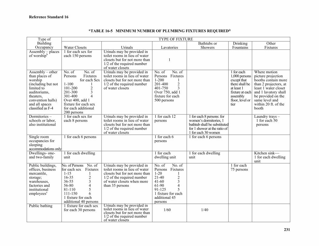
Reference Standard 16
231
*TABLE 16-5 MINIMUM NUMBER OF PLUMBING FIXTURES REQUIREDa
TYPE OF FIXTUREType ofBuilding
Occupancy Water Closets Urinals LavatoriesBathtubs or
ShowersDrinkingFountains
OtherFixtures
Assembly – placesof worshipb
1 for each sex foreach 150 persons
Urinals may be provided intoilet rooms in lieu of waterclosets but for not more than1/2 of the required numberof water closets
1
Assembly – otherthan places ofworship(including but notlimited toauditoriums,theaters,convention halls)and all spacesclassified as F-4
No. of No. ofPersons Fixtures
for each Sex1-100 1101-200 2201-300 3301-400 4Over 400, add 1fixture for each sexfor each additional200 persons
Urinals may be provided intoilet rooms in lieu of waterclosets but for not more than1/2 of the required numberof water closets
No. of No. ofPersons Fixtures1-200 1201-400 2401-750 3Over 750, add 1fixture for each500 persons
1 for each1,000 personsexcept thatthere shall beat least 1fixture at eachassemblyfloor, level ortier
Where motionpicture projectionbooths contain morethan 2 projectors, atleast 1 water closetand 1 lavatory shallbe provided on thesame level andwithin 20 ft. of thebooth
Dormitories –schools or labor,also institutional
1 for each sex foreach 8 persons
Urinals may be provided intoilet rooms in lieu of waterclosets but for not more than1/2 of the required numberof water closets
1 for each 12persons
1 for each 8 persons: forwomen’s dormitories, 1bathtub shall be substitutedfor 1 shower at the ratio of1 for each 30 women
Laundry trays – 1 for each 50 persons
Single roomoccupancies forsleepingaccommodations only
1 for each 6 persons 1 for each 6persons
1 for each 6 persons
Dwellings- one-and two-family
1 for each dwellingunit
1 for eachdwelling unit
1 for each dwellingunit
Kitchen sink1 for each dwellingunit
Public buildings,offices, businessmercantile,storage;warehouses,factories andinstitutionalemployeesc
No. of Persons No. offor each sex Fixtures
1-15 116-35 236-55 356-80 481-110 5111-150 61 fixture for eachadditional 40 persons
Urinals may be provided intoilet rooms in lieu of waterclosets but for not more than1/2 of the required numberof water closets when morethan 35 persons
No. of No. ofPersons Fixtures1-20 121-40 241-60 361-90 491-125 51 fixture for eachadditional 45persons
1 for each75 persons
Public bathing 1 fixture for each sexfor each 30 persons
Urinals may be provided intoilet rooms in lieu of waterclosets but for not more than1/2 of the required numberof water closets
1/60 1/40

Reference Standard 16
232
*TABLE 16-5 MINIMUM NUMBER OF PLUMBING FIXTURES REQUIREDa (Continued)TYPE OF FIXTUREType of
BuildingOccupancy Water Closets Urinals Lavatories
Bathtubs orShowers
DrinkingFountains
OtherFixtures
Schools: Elementary Secondary
1 fixture for each sexfor each 35 students
Urinals may be provided in toiletrooms in lieu of water closetsbut for not more than 1/2 ofthe required number of waterclosets
1/50 pupils1/50 pupilsOver 300 pupils1/100 pupils
In gym or poolshower rooms, ¼ pupilsof the largest class usingpool at any one time
1/50persons butat least 1per floor
Workers portablefacilities
1/30 workers 1/30 workers At least 1 perfloor equivalentfor each 100workmen
Industrial -foundries only
No. of No. ofPersons Fixtures1-10 111-25 226-50 351-80 481-125 51 additional fixturefor each additional 45persons
Where more than 10 menare employed:No. of Menc No. of Urinals11-29 130-79 21 additional fixture for eachadditional 80 males.Urinals may be provided intoilet rooms in lieu of waterclosets but for not more than ½of the required number ofwater closets
No. of No. ofPersons Fixtures1-8 19-16 217-30 331-45 446-65 51 additionalfixture for eachadditional 25persons
1 shower for each 15persons exposed toexcessive heat oroccupational hazardfrom poisonous,infectious, or irritatingmaterial
1 for each75 persons
Hospital and Institutions, See Section P114.0Swimming pools, See Section P116.0 Other FixturesKitchens forpublic oremployees dining
1 lavatory for thepersonal use of kitchenemployees
One machine or a 3-compartment sinkfor the effective washing and sanitizingof all cutlery, dishes and glasses beforere-use.
Dwellingsmultiple orapartment
1 for each dwellingunit or apartment
1 for each dwelling unitor apartment
1 for eachdwelling unitor apartment
Kitchen sink- 1 for each dwelling unitor apartment. Within each dwellingunit, not designed for use by transients,one laundry tray or automatic laundrywashing machine; or in a readilyaccessible location within a generallaundry room, 1 two-compartmenttray for each 10 dwelling units or 1automatic laundry washing machinefor each 20 dwelling units.
Notes for Table 16-5:aThe population used in determining the number of fixtures required shall be based on the number of people to occupy the space but in no case shall the population be less than that determined byallowing 125 sq. ft. of net floor area per person.b Such facilities may be in adjacent buildings under the same ownership or control, and shall be accessible during periods when the assembly space is occupied.c Facilities for employees in a storage building or warehouse may be located in an adjacent building, under the same ownership, where the maximum distance of travel from the working space to thetoilet facilities does not exceed 500 ft. horizontally.*Local Law 45-1984; Local Law 61-1969
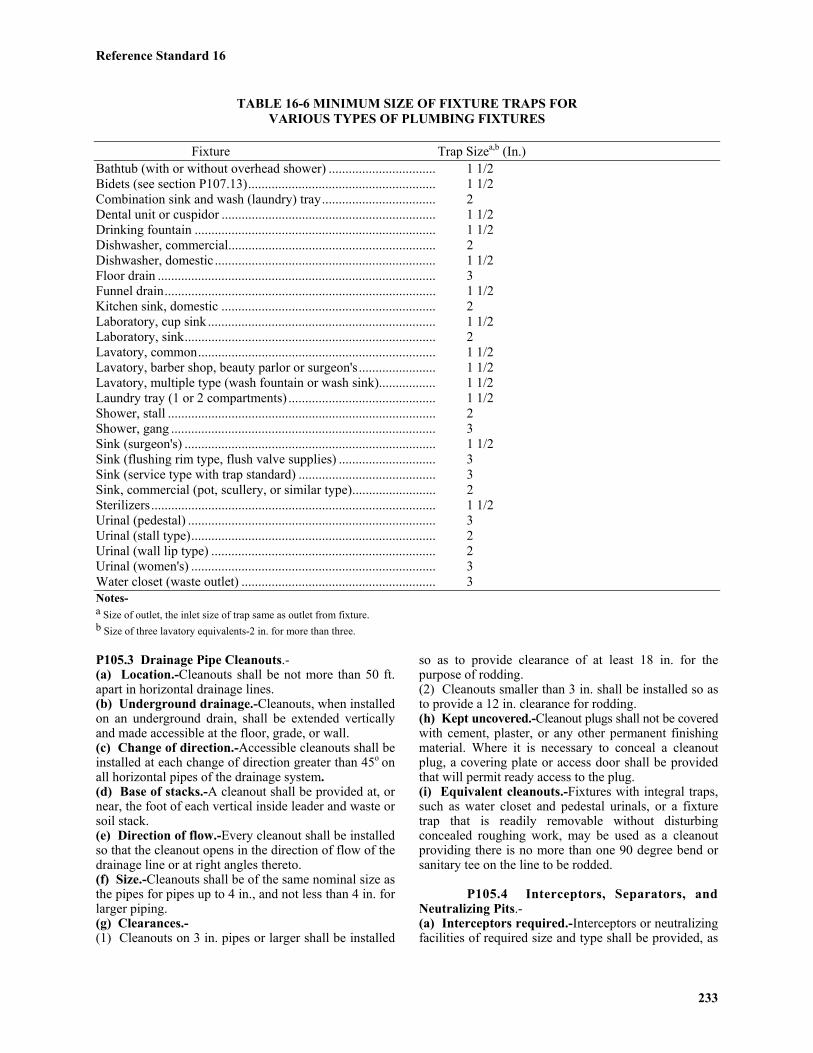
Reference Standard 16
233
TABLE 16-6 MINIMUM SIZE OF FIXTURE TRAPS FORVARIOUS TYPES OF PLUMBING FIXTURES
Fixture Trap Sizea,b (In.)Bathtub (with or without overhead shower) ................................ 1 1/2Bidets (see section P107.13)........................................................ 1 1/2Combination sink and wash (laundry) tray.................................. 2Dental unit or cuspidor ................................................................ 1 1/2Drinking fountain ........................................................................ 1 1/2Dishwasher, commercial.............................................................. 2Dishwasher, domestic .................................................................. 1 1/2Floor drain ................................................................................... 3Funnel drain................................................................................. 1 1/2Kitchen sink, domestic ................................................................ 2Laboratory, cup sink .................................................................... 1 1/2Laboratory, sink........................................................................... 2Lavatory, common....................................................................... 1 1/2Lavatory, barber shop, beauty parlor or surgeon's....................... 1 1/2Lavatory, multiple type (wash fountain or wash sink)................. 1 1/2Laundry tray (1 or 2 compartments) ............................................ 1 1/2Shower, stall ................................................................................ 2Shower, gang ............................................................................... 3Sink (surgeon's) ........................................................................... 1 1/2Sink (flushing rim type, flush valve supplies) ............................. 3Sink (service type with trap standard) ......................................... 3Sink, commercial (pot, scullery, or similar type)......................... 2Sterilizers..................................................................................... 1 1/2Urinal (pedestal) .......................................................................... 3Urinal (stall type)......................................................................... 2Urinal (wall lip type) ................................................................... 2Urinal (women's) ......................................................................... 3Water closet (waste outlet) .......................................................... 3Notes-a Size of outlet, the inlet size of trap same as outlet from fixture.b Size of three lavatory equivalents-2 in. for more than three.
P105.3 Drainage Pipe Cleanouts.-(a) Location.-Cleanouts shall be not more than 50 ft.apart in horizontal drainage lines.(b) Underground drainage.-Cleanouts, when installedon an underground drain, shall be extended verticallyand made accessible at the floor, grade, or wall.(c) Change of direction.-Accessible cleanouts shall beinstalled at each change of direction greater than 45o onall horizontal pipes of the drainage system.(d) Base of stacks.-A cleanout shall be provided at, ornear, the foot of each vertical inside leader and waste orsoil stack.(e) Direction of flow.-Every cleanout shall be installedso that the cleanout opens in the direction of flow of thedrainage line or at right angles thereto.(f) Size.-Cleanouts shall be of the same nominal size asthe pipes for pipes up to 4 in., and not less than 4 in. forlarger piping.(g) Clearances.-(1) Cleanouts on 3 in. pipes or larger shall be installed
so as to provide clearance of at least 18 in. for thepurpose of rodding.(2) Cleanouts smaller than 3 in. shall be installed so asto provide a 12 in. clearance for rodding.(h) Kept uncovered.-Cleanout plugs shall not be coveredwith cement, plaster, or any other permanent finishingmaterial. Where it is necessary to conceal a cleanoutplug, a covering plate or access door shall be providedthat will permit ready access to the plug.(i) Equivalent cleanouts.-Fixtures with integral traps,such as water closet and pedestal urinals, or a fixturetrap that is readily removable without disturbingconcealed roughing work, may be used as a cleanoutproviding there is no more than one 90 degree bend orsanitary tee on the line to be rodded.
P105.4 Interceptors, Separators, andNeutralizing Pits.-(a) Interceptors required.-Interceptors or neutralizingfacilities of required size and type shall be provided, as
Reference Standard 16
234
specified herein, for extracting oil, grease, sand, andother substances, harmful or hazardous to the buildingdrainage system, the public sewers, or sewer system asdefined in the regulation and the industrial waste permitissued by the department of public works.(b) Interceptors not required.-A grease interceptor isnot required for individual dwelling units or any privateliving quarters.(c) Separators required.-At repair garages, gasolinestations with grease racks, grease pits, work racks, andat factories where oily and/or flammable liquid wasteare produced, separators of required size and typeshall be installed into which all oil-bearing, grease-bearing, and/or flammable wastes shall be dischargedbefore emptying into the building drainage system orother point of disposal. A sand interceptor shall beprovided for auto laundries, and no oil separator shallbe required.(d) Grease interceptors.-(1) COMMERCIAL BUILDING.-A grease interceptor,meeting the provisions of this reference standard, shallbe installed in the waste line leading from pot sinks,scullery sinks, food scrap sinks, floor drains receivingwaste or spillage from soup or stock kettles, and the scrapersection of commercial dishwashers in all restaurants, kitchens,cafeterias, clubs, or other establishments where greasecan be introduced into the drainage system. No rinsewater at a temperature of 1800 F or higher shall dischargethrough the interceptor.(2) NUMBER OF GREASE INTERCEPTORS.-Oneinterceptor shall be permitted for all fixtures requiring theinterceptor, provided it is individually trapped and vented,and an additional vent is installed at the interceptor, andprovided the size of the interceptor is sufficient toaccommodate all of the fixtures connected thereto.(3) USE AS A TRAP.-The interceptor may be used inlieu of an individual fixture trap if the developed lengthfrom the fixture outlet to the inlet of the interceptor isnot more than 48 in.(4) CAPACITY.-Grease interceptors shall have a greaseretention capacity, in lbs. equal to at least twice thenumerical flow-through rating in gpm (i.e., 2 gpm=4lbs.). The minimum flow-through rating of greaseinterceptors shall be equal to the maximum value of allsinks and receptacles that may flow simultaneouslythrough the interceptor divided by the average time forthe sinks and receptacles to empty. Interceptors shall removean average at least of 90 percent of the grease of otherextractable matter in the waste water and shall conformwith the requirements of the department of public works.(5) MATERIAL.-All prefabricated grease interceptorsshall be approved.(e) Oil and flammable liquids separator.-(1) SEPARATION OF LIQUIDS.-A mixture of lightand heavy liquids having various specific gravities,such as petroleum hydrocarbons in water, may betreated and then separated in a receptacle complyingwith the provisions of this reference standard.
(2) DESIGN OF SEPARATOR.-a. Overall requirements.-Oil separators shall have adepth of at least 2 ft. below the invert of the dischargedrain connected thereto. The outlet opening of theseparator shall have at least an 18 in. water seal.b. Motor vehicle occupancies.-In automotive servicestations, automotive repair shops, and public garages(group I) where not more than four motor vehicles areboth serviced and stored, separators shall have a minimumcapacity of 6 cu. ft. and 1 cu. ft. capacity shall be addedfor each vehicle up to ten vehicles. Above ten vehicles,the size of the separator shall be determined by anarchitect or engineer, subject to the approval of theCommissioner. Where vehicles are serviced only andnot stored, separator capacity shall be based on netcapacity of 1 cu. ft. for each 100 sq. ft. of surface to bedrained into the separator, with a minimum of 6 cu. ft.c. Other occupancies.-In other buildings where oil orother flammable liquids are stored or used, no physicalconnection or internal arrangement that could permit theaccidental or deliberate introduction of such materialsdirectly or indirectly into the sewer system will bepermitted. Where such substances might overflow byspillage or other circumstance not attributable to a directconnection of the plumbing system, every precautionshall be taken through the presence of protective dikesand similar devices to prevent such substances fromreaching the public sewers.(3) VENTING.-Oil separators shall be vented in accordancewith Section P105.6.(4) CONNECTION TO SEWER.-The discharge of anoil separator shall be independently connected to thestreet sewer or to the sewer side of the house trap.Where the oil separator is located below the street sewer,the sump receiving the effluent from the separator shallbe gastight and vented in the same manner as the separator.(5) OIL STORAGE TANK.-Each separator shall havean oil storage tank available for storing the residue fromthe separator. Tanks shall be installed in accordancewith Article 14.
P105.5 Interceptors, Separators, and NeutralizingPits for Specific Services.-(a) Sand interceptors-commercial establishments.-Sand and similar interceptors for heavy solids shall beso designed and located as to be readily accessible forcleaning, and shall have a water seal of at least 6 in.(b) Laundries.-Commercial laundries shall be equippedwith an interceptor having a wire basket or similardevice that is removable for cleaning, and that willprevent passage into the drainage system of any solids1/2 in. or larger in size, or strings, rags, buttons, orother materials detrimental to the public seweragesystem. Interception within a trough will be permitted.(c) Bottling establishments.-Bottling plants shalldischarge their process wastes into an interceptor thatwill intercept broken glass and other solids beforedischarging liquid wastes into the drainage system.
Reference Standard 16
235
(d) Slaughter houses.-Slaughtering room and dressingroom drains shall be equipped with separators or interceptorsthat shall prevent the discharge into the drainage systemof feathers, entrails, and other materials likely to close thedrainage system.(e) Laboratories, dyeworks, and chemical plants.-Inestablishments discharging sewage, industrial wastes,or other wastes that will reduce the pH value of thewaste water discharged to the public sewer system below4.5 or raise it to above 11.5 at the point or points of suchdischarge, provisions shall be made for neutralizingsuch waste water to conform with the regulations of thedepartment of public works. Where applicable, a suitableneutralizing pit shall be installed that is of sufficientcapacity to hold an adequate quantity of marble chips orsimilar neutralization substance to satisfactorily bring thepH value of the waste water to acceptable values. Bafflesand other flow guiding devices may be introduced to insurethat the acid or alkaline wastes are thoroughly contactedby the neutralizing substance. The venting arrangementfor this pit shall be in conformance with the applicableprovisions of this code.
P105.6 Venting of Interceptors, Separators,and Neutralizing Pits.-(a) Oil interceptors and separators.-(1) Interceptors and separators shall be so designed thatthey will not become air bound if closed covers areused. Each interceptor or separator shall have an individual3 in. vent extending from the top of the separator to theoutside air at a point at least 12 ft. above street level.(2) A fresh air inlet shall be provided from the drainline at the inlet side of the separator to the outside air ata point at least 6 in. above grade.(3) A separator shall be accepted in lieu of a house trap.(4) The horizontal drain line and at least one stack shallbe at least 3 in. in diameter. Stack shall be carried fullsize through the roof.(b) Neutralizing pits and interceptors (other thanoil).-Interceptors, separators, and neutralizing pits shallbe so designed that they will not become air bound ifclosed covers are used. Each interceptor that is providedwith a cover shall be vented, and the vent may connectinto the sanitary vent system.
P105.7 Accessibility of Interceptors, Separatorsand Neutralizing Pits.-Each interceptor, separator, andneutralizing pit shall be so installed that it is readilyaccessible for removing the cover, for servicing, and formaintenance.
P105.8 Maintenance of Interceptors, Separators,and Neutralizing Pits.-Interceptors, separators, andneutralizing pits shall be maintained in efficient operatingcondition by periodic removal of accumulated grease,scum, oil, or other floating substances, and solids depositedin the interceptor, separator, or neutralizing pit. Impropermaintenance of interceptor, separator, or neutralizing pit
may constitute sufficient cause for revocation of theindustrial waste permit for the premises issued by thedepartment of public works or may constitute a violationof the fire prevention code.
P105.9 Backwater Valves.-(a) Fixtures and area drains subject to backflow.-Where fixtures, floor drains, or area drains are subjectto overflow as the result of backwater from the publicsewer system, accessible backwater valves shall beinstalled in the fixture drain pipe from such fixture, inthe branch drain to such area drain or group of fixtures,or in the building drain at its point of exit from thebuilding and downstream from the building trap.Masonry access manholes shall be provided when thecenterline of any drain line is 18 in. or more below aslab on grade.(b) Design.-Backwater valves shall provide a positivemechanical seal against backwater, and when fullyopened shall have the same discharge flow capacity asthe pipe in which it is installed. All bearing parts shallbe made of corrosion resistant metal or other equivalentmaterial. The flap shall be so designed as to hangpartially open when not subject to backwater pressure.
P105.10 Industrial Wastes Sampling Manholes.-All premises intended for the discharge of sewage,industrial wastes, or other wastes with characteristics that donot conform to those prescribed for normal sewage asdefined in regulations promulgated by the department ofpublic works, shall contain a suitable common controlmanhole into which all flow of sewage, industrial wastes,or other wastes are combined. When the installation ofsuch a common manhole is impossible, impractical, orwill interfere with treatment facilities required for theissuance of an industrial waste permit by the departmentof public works, the owner of such premises shallconstruct, in lieu of the common manhole, two or moremanholes as required by the department of publicworks, for accurate measurement of all flows of sewage,industrial wastes, or other wastes before dischargingfrom such premises into the sewer system.
Section P106.0 Hangers and SupportsP106.1 Material.-Hangers, anchors, and
supports shall be of metal or equivalent material ofsufficient strength to support the piping and its contents.Piers may be of concrete, brick, or equivalent material.
P106.2 Attachment to Building.-Hangers andanchors shall be securely attached to the buildingconstruction at sufficiently close intervals to uniformlysupport the piping and its contents.
P106.3 Intervals of Supports.-(a) Vertical piping.-Vertical piping of the followingmaterials shall be supported, using either guide or frictionhangers or a combination of both, at the following intervals:
Reference Standard 16
236
(1) Cast iron soil pipe at base and at each story height,but in no case at intervals greater than 20 ft.(2) Threaded pipe (SPS).-At every other story height,but in no case at intervals greater than 25 ft.(3) Copper tubing (hard temper).-At each story height.(4) Other materials.-As required for structural stabilityand service.(b) Horizontal piping.-Horizontal piping of thefollowing materials shall be supported at intervals nogreater than the following:(1) Cast iron soil pipe.-At 5 ft. intervals and behindevery hub.(2) Threaded pipe (1 in. or less).-At 8 ft. intervals.(3) Threaded pipe (1 1/4 in. or over).-At 12 ft. intervals.(4) Copper tubing (1 1/4 in. or less).-At 6 ft. intervals.(5) Copper tubing (1 1/2 in. or over).-At 10 ft. intervals.(6) Other materials.-As required for structural stabilityand service.(c) Base of stacks.-Bases of cast iron stacks shall besupported on concrete, on brick laid in cement mortar, bymetal brackets attached to the building construction, or byequivalent methods. Stacks of other material shall be anchoredso as to relieve the load from the base of the stack.
*P106.4 Installation of no-hub type cast iron soilpipe, fittings, and couplings.-All installations of no-hub type cast iron soil pipe,fittings and couplings shall comply with the following:CISPI Designation 310-1985 Specification for Cast IronSoil Pipe Institute's Approved Coupling for Use inConnection with Hubless Cast Iron Soil Pipe and Fittingsfor Sanitary and Storm Drain, Waste, and Vent PipingApplications.*Local Law 100-1989
Section P107.0 Water Supply and DistributionP107.1 Permits.-
(a) Permits for all water supplies for all buildings or fordemolitions shall be obtained from the department ofwater supply, gas, and electricity. The installation of thewater service system from the street main up to andincluding the meter setting when meters are required, orup to the house control valve when no meters arerequired, shall be subject to inspection and approval bythe department of water supply, gas and electricity.(b) Permits for sidewalk and street openings shall beobtained from the department of highways.
P107.2 Water Service.-(a) Taps to city water mains.-(1) SEPARATE SUPPLY.-A separate tap and serviceshall be installed for each building fronting on a streetin which there is a city (street) water main, and noconsumer will be allowed to supply water to otherpersons or premises, except in a project where morethan one building under a single ownership is suppliedfrom a common house tank or booster system located inor on one of the buildings.
(2) CONNECTIONS TO CITY (STREET) MAINS.-Corporation stops, wet connections, or other connectionsto a street main shall be made only by the department ofwater supply, gas and electricity employees. The cost ofthe installation shall be borne by the owner of theproperty for which the connection is made.(3) DESTRUCTION OF ABANDONED CORPORATIONSSTOPS AND WET CONNECTIONS.- All driven corporationstops, when abandoned, shall be removed and replacedby plugs. All wet connections or screw corporationstops, when abandoned, shall be destroyed in place, andall exposed portions of the service pipe shall be cut andremoved. Where a corporation stop or wet connection isdestroyed and the connecting service pipe is one that isequipped with a curb valve and box, the curb box shallbe removed. The expense in connection with theabandonment or destruction of a corporation stop or wetconnection shall be chargeable to the owner of theproperty into which the service pipe entered.(b) Service.-(1) SERVICE PIPES, DEFINITION.-See Section P100.0.(2) SIZE OF TAPS AND WATER SERVICE.-Thesize of service pipe to supply a premise shall be basedupon the water demand load of the premises asdetermined by "fixture units". "Fixture units" shallconform to the requirements of the department of watersupply, gas, and electricity. In premises used forcommercial and industrial purposes where it is notfeasible to determine the size of the service pipe on thebasis of "fixture units," the size of the service pipe shallbe based upon the water demand load of the premises.The minimum size service shall be 1 in. in diameter, andthe gooseneck shall be the same size as the service pipe.(3) SIZE OF FIRE LINE SERVICE.-Sizes of connectionsfor fire service shall be subject to the requirements ofthe department of water supply, gas, and electricity.(4) SEPARATION OF WATER SERVICE ANDBUILDING SEWER.-Except as permitted below, theunderground water service and the building sewer shallbe at least 10 ft. apart horizontally, and shall be separatedby compacted earth. The water service may be placed inthe same trench with the building sewer and buildingdrain under the following conditions:a. The sewer is of cast iron with leaded or mechanical joints.b. The bottom of the water service, at any point, shallbe at least 12 in. above the top of the sanitary orcombined sewer line.c. The water service shall be placed on a continuousshelf of compacted earth, excavated at one side of thecommon trench.d. The water service pipe shall have a minimum numberof joints.(5) WATER SERVICE NEAR SOURCES OF POLLUTION.-Potable water service pipes shall not be located in,under, or above any cesspools, septic tanks, septic tankdrainage fields, or seepage pits. A separation of 10 ft.horizontally shall be maintained.(6) PROTECTIVE COVER FOR SERVICE PIPE.-All
Reference Standard 16
237
water services shall be installed and maintained at adepth of at least 4 ft. below the finished outside groundsurface. Where a service pipe has less than 4 ft. ofcover due to subsurface conditions, it shall be insulatedand protected as required by the department of watersupply, gas, and electricity.(7) INSTALLATION OF SERVICE PIPE.-Each newservice pipe shall be laid in a straight line at rightangles to the street main and extending from the tap tothe main house-control valve. Where the surface orsubsurface conditions make it impracticable to install aservice pipe in accordance with the above conditions, itmay be laid differently provided a sketch or plan showingthe proposed alternate location of the service pipe issubmitted to and approved by the department of watersupply, gas and electricity. The driving of a service pipethrough the ground is prohibited.**(8) GOOSENECKS ON SERVICE PIPE.-Connections to the city main by cast iron or ductile ironpipe may be made directly; no offset swing joint will berequired. Each copper tubing service pipe shall havean excess of at least 3 ft. of pipe formed in a gooseneckat the connection to the tap and laid to the right side,facing the tap. Each brass or copper service pipe shallhave, at the tap or wet connection, a copper tubinggooseneck of at least 3 ft. of pipe, or an offset swingjoint consisting of four elbows and three pieces of pipeeach at least 2 ft. in length, laid to the right side, facingthe connection.Where buildings are constructed on pile foundations orother unyielding supports, the service pipes of materialother than cast iron or ductile iron shall have twogoosenecks, one at the tap and one immediately outsidethe building. A sleeve shall be installed to carry theservice through the foundation wall.**Local Law 29-1987(9) CURB VALVES.-Curb valves shall be installed onall fire service pipes. They shall be installed on alldomestic service pipes over 2 in. in diameter and at theoption of the owner, on service pipes 2 in. or less indiameter. The curb valves and boxes shall be set in theservice pipe in the sidewalk area at the curb or within 2ft. of the curb. Curb valves shall be of the gate typenonrising stem valve, designed for a minimum of 150psi wwp.Access to all curb valves installed shall be provided bya tar coated iron extension box with cover, and the covershall be flush with the sidewalk level. Curb valves 2 in.and less in diameter may be equipped with a wheel foroperation, provided a permanent 1/2 in. diameter ironrod is attached thereto and extended to the top of thecurb box. No curb valve shall be installed in a driveway.Curb valves larger than 2 in. in diameter shall beequipped with an operating nut at least 1 1/4 in. squareand no extension rod need be attached thereto. Suchoperating nut may be installed on curb valves 2 in. andless in diameter at the option of the owner.In sprinkler and fire line installations, the location of
the sidewalk control valve shall be governed by theprovisions of the building code.(10) CLEARANCE.-Clearance shall be provided arounda water service pipe passing through a wall to protect itagainst the following:a. Chemical action from direct contact with concrete.b. Distortion or rupture of water service pipe from shearingaction due to settlement.c. Distortion or rupture of the water service pipe causedby expansion or contraction.Clearance shall not be less than 1/2 in. between theoutside of the pipe and the wall. Sleeves or arches maybe used to provide the wall opening. The space betweenthe pipe and the wall structure or the sleeve shall becarefully packed or caulked with lead or waterproofmaterial resistant to vermin and rodents.(11) TEST OF SERVICE OF SERVICE PIPE.-In thepresence of the tapper or inspector of the department ofwater supply, gas, and electricity, each new service pipeor repaired service pipe shall be subjected to a watertest made under the street main pressure. All pipes andappurtenances shall remain uncovered for the durationof the test and shall show no sign of leakage. When anyquestion arises as to the installation conforming withthese regulations, an internal hydrostatic test as specifiedfor materials may be applied, subject to the approval ofthe department of water supply, gas, and electricity.***(12) HOUSE CONTROL VALVES.-The housecontrol valve shall be of the gate or full port ball type,and shall be placed in the service pipe inside thebuilding within 2 ft. of the building foundation wall andlocated so as to be accessible at all times. All valvesshall be designed for a minimum of 150 psi and gatevalves may be of the outside screw and yoke type.***Local Law 10-1999.
P107.3 Meters.-(a) Where required.-(1) BUILDINGS UNDER CONSTRUCTION.-Allwater used in the construction of buildings 75 ft. or sixstories or more in height shall be metered. Prior to thecommencement of actual building construction, a meter ofproper size shall be installed on each tap or service supplyingthe premises. It shall be placed in an accessible locationclose to the point of entry of the service pipe, as designedby the department of water supply, gas and electricity.Each meter shall be enclosed in a vault or box capableof providing adequate protection against damage or injuryfrom frost or any other cause. Each meter shall remain inservice throughout the entire period of building construction,and thereafter until such time as the annual water chargesfor the structure becomes effective or the permanent meterhas been installed. No permit will be issued for theinstallation of a meter to register the supply of water usedfor the construction of a building six stories in height orless. Such water will be charged for as required by thedepartment of water supply, gas, and electricity.*(2) FIRE LINES. Combined fire/domestic service for
Reference Standard 16
238
new sprinkler systems in residential buildings up to sixstories or seventy-five feet in height may use one fire-rated compound meter on the combined service or astandard displacement meter on the domestic branchand a detector check valve assembly on the fire branch.If a fire-rated compound meter is used, it shall becertified or listed by the Underwriters Laboratories orThe Factory Mutual System or an equivalent nationallisting organization.*Reference to Local Law 5-1973 removed by Local Law 10-1999. (3) REFRIGERATION AND AIR CONDITIONING.-Where the rate of water required for operation ofrefrigeration and air conditioning apparatus exceeds 1/2gpm, the building supply shall be metered, as requiredby the department of water supply, gas, and electricity.(4) MISCELLANEOUS FIXTURES.-The following fixturesor devices shall not be installed or used except wherethe supply of water to the fixture or devices is meteredor connected to a metered distribution system: displayfountains containing over 1,000 gal. of water; aquariumscontaining over 300 gal. of water; irrigation systems;swimming tanks, wading pools, or plunge baths containingmore than 5,000 gal. of recirculated water; or hydrotherapydevices requiring the use of city water for their operation.(b) Location of meters.-In all premises where the supplyof water is to be fully metered, the meter shall be setwithin 3 ft. of the building foundation or vault wall atthe point of entry service pipe. The service pipe betweenthe house control valve and the meter shall be kept exposed.When a building is situated in back of the street line orwhen conditions exist in a building that prevent thesetting of the meter at a point of entry, the meter maybe set outside of the building within the property line,provided the meter is installed in an accessible, watertight,and frost-proof pit or meter box. All meter locationsshall be subject to approval by the department of watersupply, gas, and electricity.(c) Setting of meters.-In setting or resetting a meter,the requirements are as follows:(1) The meter shall be set so that the dial faces upwardand is horizontal. The dial shall not be more than 3 ft.above the floor.(2) Connections shall be made by a coupling, union, orflange union on both the inlet and outlet end of themeter and bored for sealing with holes at least 3/32 in.in diameter. Union or couplings that would permitremoving the meter setting without breaking the sealwiring are prohibited.(3) A house valve shall be installed in the service pipeon the inlet side of the meter within 1 ft. of meterexcept that when a current meter is set, a straightsection of pipe with a length of eight times of diameterof the meter inlet size, shall be installed immediatelybefore the inlet between the control valve and the meterwith no fittings of any kind installed in the straightsection of pipe.(4) A valve shall be installed on the outlet of all metersof 1 in. size or larger.
(5) A full sized test tee shall be placed on all 1 1/4 in., 11/2 in., and 2 in. meters, on the outlet between themeter and the outlet valve, with a short, capped nipplein the tee.(6) A test tee with a 2 in. opening shall be placed on allmeters 3 in. and larger on the outlet between the meterand outlet valve with a short nipple in the tee, and a 2in. valve shall be placed on the nipple.(7) All meters not equipped with a test tee and outletvalve shall have a tee with a faucet in it inserted in theline on the outlet side within 2 ft. of the meter, exceptthat this requirement may be waived where otherreadily accessible means are provided for testing themeter to determine whether the meter is registering correctly.(8) No connection shall be made to a test tee.(9) Before setting meters 3 in. and larger, a plan orsketch showing the proposed installation, and indicatingthe location of service control valve inside of thebuilding, the distance of the meter from the point ofentry of service, the height from floor, the size and thetype of meter, and the approximate date of setting shallbe filed in duplicate with the department of watersupply, gas and electricity for approval.(d) Size and type of meter.-(1) APPROVED METERS.-Meters shall conform tostandards approved by the department of water supply,gas, and electricity.(2) SIZE.-A meter shall be restricted to a size that willgive accurate registration on the basis of consumptionand occupancy of the premises or portion of thepremises metered. The meter in no case may be morethan one standard size larger than the tap or connectionto the city main. The piping of the meter setting fromthe inlet valve to the outlet valve shall be of the samesize as the meter. Where inaccuracy of registration isfound to be due to the improper size of the meter, suchmeter shall be replaced with another meter of a sizedesignated by the department of water supply, gas, andelectricity.
P107.4 Check Valves.-(a) A check valve shall be placed in all services whereone of the following conditions exist:(1) Where a building is supplied by services connectedto different mains.(2) Where there is any possibility of backflow fromtanks, siamese connections, or other apparatus or fixtureswithin the building.(b) Such check valves shall be placed within 2 ft. of theoutlet side of the main house-control valve or on themetered connections between the meter test tee and theoutlet valve.
P107.5 Water Supply Distribution System.-(a) Design, adjustment, and maintenance.-The watersupply distribution system shall be designed and adjustedto supply fixtures and equipment with the amount ofpotable water required for proper use, cleansing and
Reference Standard 16
239
performance. Pipe sizing shall be predicated onhydraulic design by an architect or engineer, subject tothe approval of the Commissioner. (b) Minimum pressure.-(1) The minimum pressure available near the faucet orwater outlet with the water outlet wide open shall be 8 psi.(2) At all other equipment and flush valves requiringmore than 8 psi, the minimum flow pressure shall bethe pressure required for satisfactory performance.(3) Where street main pressure fluctuates, the buildingwater distribution system shall be designed for theminimum pressure available.(c) Inadequate water pressure in street mains.-Whenever water pressure from the street main or othersource of supply is insufficient to provide pressures atfixture outlets, an auxiliary supply shall be provided in
accordance with Section P107.7.(d) Maximum pressures.-Where the static or streetmain pressure exceeds 85 psi on fixtures, a pressurereducing valve shall be installed to reduce the pressureto 85 psi or less at the fixture with no flow and thefixture closed. Sillcocks and outside hydrants may beleft at full pressure.(e) Minimum size of water supply branches and risers.-(1) The minimum size of an individual branch supply to afixture shall be predicated on supplying the flow of waterlisted in Table RS 16-7 at velocities not in excess of 8 fps.(2) The branches, risers, and headers shall be sized toproduce velocities not in excess of 8 fps for the flowpredicated on the probable demand of flow in thebranch, riser, or header pipe.
TABLE RS 16-7 MINIMUM RATE OF FLOW AND MINIMUM REQUIRED PRESSURE DURING FLOW FORSIZING INDIVIDUAL BRANCH SUPPLIES FOR PLUMBING FIXTURES
Flow Pressurea Flow RatebLocation (psi) (gpm)
Ordinary basin faucet .............................. 8 2.0Self-closing basin faucet.......................... 8 2.5Sink faucet, 3/8 in. ................................... 8 4.5Sink faucet, 1/2 in. ................................... 8 4.5Bathtub .................................................... 8 5.0Laundry tub cock, 1/2 in. ......................... 8 5.0Shower ..................................................... 8 5.0Ball-cock for closet .................................. 8 3.0Flushometer valve for closet .................... 10-20 15-40c
Flushometer valve for urinal .................... 10 15.0Drinking fountains ................................... — 0.75Notes-a The flow pressure is the pressure in the supply pipe, near the faucet or water outlet while the faucet or water outlet is wide open and flowing.bAt fixtures supplied with both hot and cold water, the flow rate indicated is for each of the two connections.cThe wide range is due to the variation in designs and types of water closet flush valves and water closets.
(f) Water hammer.-All building water supply systemsshall be provided with devices to absorb shocks resultingfrom high pressure caused by the quick closing of valves.These pressure absorbing devices shall be either airchambers or mechanical devices. Water pressure shockabsorbers may be installed at the end of long pipe runsor near batteries of fixtures.(1) Air chambers installed on the main service shall bein an accessible place, and each air chamber shall beprovided with a means for restoring the air should thechamber become waterlogged.(2) Air chambers installed at individual fixtures need notbe accessible. Air chambers for fixtures shall be at least12 in. long and of the same diameter as the branch pipeconnection; for quick closing valves the chamber shall beat least 18 in. long. One air chamber may service a batteryof fixtures provided the single air chamber is at least 24in. long and is at least the size of the supply branch.(3) Mechanical devices shall be used in accordancewith the manufacturers' specifications as to location andmethod of installation.
P107.6 Water Supply Control Valves.-(a) Stop-and-waste valves prohibited.-Combinationstop-and-waste valves or cocks shall not be installed inunderground or buried water supply piping.(b) Riser valves.-Except in a one-family dwelling, avalve shall be installed at the foot of each water supplyriser. In multistory buildings, a valve shall be installedat the top of each water supply down-feed pipe.(c) Valves in dwelling units.-In two-family dwellingsand in dwelling units of buildings classified in occupancygroup J-2, control valves on the supply branch or stopvalves on each individual fixture shall be provided sothat the water to any dwelling unit may be shut offwithout stopping the flow of water to other units.(d) Individual fixture valves.-In buildings of occupancyother than those in (c) above, the supply branch to thegroup of fixtures or the supply branch to each fixture orpiece of equipment shall be provided with a valve or afixture stop valve to shut off the water to the fixture orto the room in which it is located.(e) Tank controls.-Supply lines to and from pressure

Reference Standard 16
240
or gravity tanks shall be supplied with valves at thetanks within the tank room.(f) Water heating equipment valve.-The cold waterbranch to each hot water storage tank or water heater shallbe provided with a valve located near the equipment.Each tank or heater shall be equipped with an approvedautomatic relief valve as prescribed in Section P107.26.(g) Accessibility.-All water supply control valves shallbe placed so as to be readily accessible for service andmaintenance.(h) Control valve design.-Except the valves servingsingle fixtures, control valves on all water lines shall,when fully opened, have a cross-sectional area of atleast 85 percent of the cross-sectional area of the line inwhich they are installed.
*(i) Bath and shower valves.-Valves for individual showersor bathtubs, or multiple gang showers shall be balancedpressure-mixing valves, or thermostatic mixing valves, orcombination pressure balancing/thermostatic valves, conformingto the requirements of ASSE 1016 (December 1988).Water temperature control valves shall be equippedwith high-limit stops adjusted to a maximum hot watersetting of 120 degrees Fahrenheit (49 degrees Celsius).*Local Law 86-1996
P107.7 Auxiliary Water Systems.-
(a) When required.-When the pressure in the street watermain or individual water supply system is insufficientto supply the probable peak demand flow to all plumbingfixtures and other water needs freely and continuously,and with the minimum pressures and quantities asprescribed in Section P107.5, or elsewhere herein, the rateof supply shall be supplemented by one of the following:(1) An elevated gravity water supply tank.(2) A hydropneumatic pressure booster system.(3) A water pressure booster pump system.(4) A combination of these systems.(5) Other systems designed by an architect or engineer,subject to the approval of the commissioner.
P107.8 Water Supply Tanks.-(a) Overflows.-Each gravity or suction water supplytank shall be provided with an overflow not smallerthan shown in Table RS 16-8 and/or RS 16-9. Thegallons per minute listed in the tables shall be the totalautomatic pump capacity connected to the tank, or thecalculated carrying capacity of the fill pipe. Theoverflow outlet shall discharge within 6 in. of a roof orroof drain, or over an open water supplied fixture. Theoverflow discharge shall be provided with durablescreening with openings of not more than 1/8 in.
TABLE RS 16-8 SIZE OF OVERFLOWS FOR GRAVITY AND SUCTION TANKS(See Figures RS 16-1 A and B)
Maximum Allowable Maximum AllowableOverflow Pipe Size gpm for each Orifice gpm for Vertical Overflow
(in.) Opening into Tank (Piping Connecting Orifices)2 19 253 43 754 90 1635 159 2966 257 4728 505 1,020
10 890 1,870 12 1,400 2,967
TABLE RS 16-9 SIZE OF WEIRS FOR GRAVITY AND SUCTION TANKS(See Figure RS 16-1C)
Slotted Weir Opening into Tank between Overflow Chamber Maximum gpm Allowable and Water Compartmenta for Weir
3 in. x 24 in. 3813 1/2 in. x 24 in. 4754 1/2 in. x 24 in. 6854 1/2 in. x 36 in. 1,0376 in. x 36 in. 1,5696 in. x 48 in. 2,100
Note-a Bottom of the overflow chamber must be at least 6 in. below weir.Bottom outlet shall be provided in the chamber of sizes based on capacities as indicated in table RS 16-8.
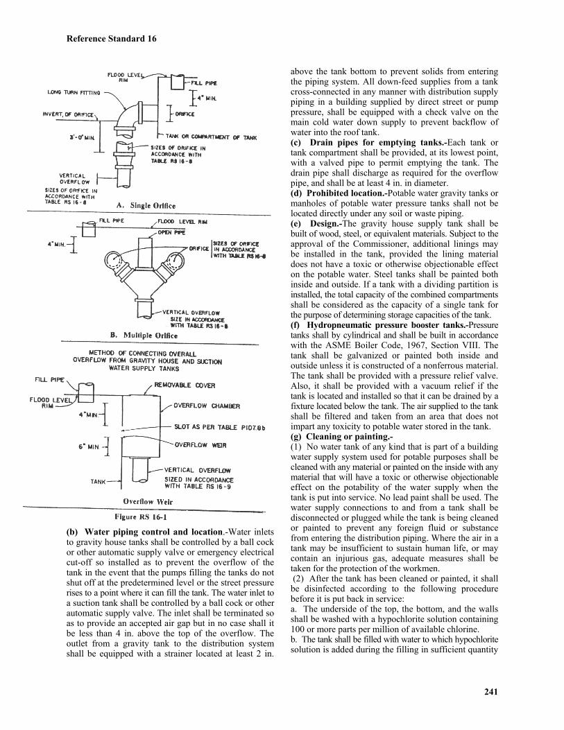
Reference Standard 16
241
(b) Water piping control and location.-Water inletsto gravity house tanks shall be controlled by a ball cockor other automatic supply valve or emergency electricalcut-off so installed as to prevent the overflow of thetank in the event that the pumps filling the tanks do notshut off at the predetermined level or the street pressurerises to a point where it can fill the tank. The water inlet toa suction tank shall be controlled by a ball cock or otherautomatic supply valve. The inlet shall be terminated soas to provide an accepted air gap but in no case shall itbe less than 4 in. above the top of the overflow. Theoutlet from a gravity tank to the distribution systemshall be equipped with a strainer located at least 2 in.
above the tank bottom to prevent solids from enteringthe piping system. All down-feed supplies from a tankcross-connected in any manner with distribution supplypiping in a building supplied by direct street or pumppressure, shall be equipped with a check valve on themain cold water down supply to prevent backflow ofwater into the roof tank.(c) Drain pipes for emptying tanks.-Each tank ortank compartment shall be provided, at its lowest point,with a valved pipe to permit emptying the tank. Thedrain pipe shall discharge as required for the overflowpipe, and shall be at least 4 in. in diameter.(d) Prohibited location.-Potable water gravity tanks ormanholes of potable water pressure tanks shall not belocated directly under any soil or waste piping.(e) Design.-The gravity house supply tank shall bebuilt of wood, steel, or equivalent materials. Subject to theapproval of the Commissioner, additional linings maybe installed in the tank, provided the lining materialdoes not have a toxic or otherwise objectionable effecton the potable water. Steel tanks shall be painted bothinside and outside. If a tank with a dividing partition isinstalled, the total capacity of the combined compartmentsshall be considered as the capacity of a single tank forthe purpose of determining storage capacities of the tank.(f) Hydropneumatic pressure booster tanks.-Pressuretanks shall by cylindrical and shall be built in accordancewith the ASME Boiler Code, 1967, Section VIII. Thetank shall be galvanized or painted both inside andoutside unless it is constructed of a nonferrous material.The tank shall be provided with a pressure relief valve.Also, it shall be provided with a vacuum relief if thetank is located and installed so that it can be drained by afixture located below the tank. The air supplied to the tankshall be filtered and taken from an area that does notimpart any toxicity to potable water stored in the tank.(g) Cleaning or painting.-(1) No water tank of any kind that is part of a buildingwater supply system used for potable purposes shall becleaned with any material or painted on the inside with anymaterial that will have a toxic or otherwise objectionableeffect on the potability of the water supply when thetank is put into service. No lead paint shall be used. Thewater supply connections to and from a tank shall bedisconnected or plugged while the tank is being cleanedor painted to prevent any foreign fluid or substancefrom entering the distribution piping. Where the air in atank may be insufficient to sustain human life, or maycontain an injurious gas, adequate measures shall betaken for the protection of the workmen. (2) After the tank has been cleaned or painted, it shallbe disinfected according to the following procedurebefore it is put back in service:a. The underside of the top, the bottom, and the wallsshall be washed with a hypochlorite solution containing100 or more parts per million of available chlorine.b. The tank shall be filled with water to which hypochloritesolution is added during the filling in sufficient quantity

Reference Standard 16
242
so that the treated water in the tank will contain at least10 parts per million of available chlorine.c. The chlorinated water shall be allowed to remain inthe tank for two hours.d. Finally, the tank shall be drained completely beforerefilling.(3) House and suction tanks shall be drained and cleanedat least once a year.(h) Supports.-All water supply tanks shall be supportedin accordance with the requirements for structural workof the building code.(i) Covers.-All water supply tanks shall be covered tokeep out dirt, vermin, and unauthorized persons.
P107.9 House and Booster Pumps.-(a) Directly off street main.-Power pumps may drawtheir water supply directly from the street main if thetotal connected automatic pump capacity is not morethan 400 gpm. If the total connected automatic capacityexceeds 400 gpm, the pumps may be connected directlyto the street main only if permitted by the department ofwater supply, gas, and electricity.(b) Suction tank.-(1) When the pumps cannot be connected directly tothe water service main a suction (surge) tank shall beinstalled. Suction tanks shall be constructed inaccordance with the requirements of Section P107.8.(2) No suction tank will be required for a fire pumpexcept where the size of the fire service is equal to orgreater than the size of the street main.(c) Suction tank size.-Suction tanks when required,shall have a capacity not less than prescribed in TableRS 16-10.
TABLE RS 16-10 SUCTION TANK SIZESTotal Connected Pump Tank Capacity
Capacity (gpm) (gal.)400-500 (7,500)
501 and over (10,000)
(d) Fill line to tank.-A fill connection to a suction tankshall be provided with a flow control that will limit thewater make-up rate to the suction tank under thepressure conditions and at the maximum quantitiespermitted by the department of water supply, gas, andelectricity.(e) Low pressure cut-off required on booster pumps.-When a pump is directly connected to the street main, alow pressure cut-off shall be installed on the house sideof each building control valve and on the street side ofeach meter assembly to prevent the pressure from droppingmore than 7 psi below the normal static pressure at thepoint of entry of the water service, or as required by thedepartment of water supply, gas, and electricity.(f) Check valves required.-Each pump discharge shallbe provided with a check valve and gate valve.
P107.10 Protection of Potable Supply.-(a) General.-A potable water supply system shall be
designed, installed, and maintained in such manner as toprevent contamination from non-potable liquids, solids, orgases from being introduced into the potable water supplythrough cross-connections or any other piping connectionsto the system.(b) Identification of potable and non-potable water.-Inall buildings having dual water distribution systems, onepotable water and the other non-potable water, each systemshall be identified either by color marking or metal tags.(c) Color marking.-When color marking is used, potablewater lines shall be painted green and non-potable waterlines shall be painted yellow. This requirement may be metby painting 3 in. wide bands, green or yellow, at intervalsof not more than 25 ft. and at points where piping passesthrough walls, floors, or roofs, in which case the bandsshall be applied to the piping on both sides of the wallsand both above and below the floor or roof. Points ofoutlets for nonpotable water shall be marked with a tagor color code.(d) Metal tags.-When tags are used, potable waterlines shall be identified by 3 in. diameter metal tagsbearing the legend "SAFE WATER" in letters at least1/2 in. high. Non-potable water lines shall be identifiedby firmly attached metal tags having the shape of a 4 in.equilateral triangle bearing the legend "WATERUNSAFE" in letters at least 1/2 in. high. As in the useof color bands, tags shall be attached to pipes atintervals of not more than 25 ft. and at both sides atpoints where pipes pass through walls, and both aboveand below points where pipes pass through floors or roofs.
P107.11 Toxic Materials and Substances.-Nomaterials or substances that could produce either toxicconditions or add taste or odor to a potable water systemshall be introduced into or used in such systems.
P107.12 Used Piping.-Piping that has beenused for any purpose other than conveying water shallnot be used for conveying potable water.
*P107.13 Prohibited Connections To FixturesAnd Equipment.-The following equipment shall receivewater supply only through air gaps and direct waterconnections to the potable water supply system shall beprohibited unless a reduced pressure principle back pressurebackflow preventer is installed between the water supplyand the equipment.(1) Bidets with submerged water connection that cannotdrain out after shut off.(2) Aspirators, injectors, ejectors or water siphons andsimilar apparatus.(3) Mortuary, dissection, operating and embalmingtables or similar equipment.(4) Sterilizers.(5) Flushing rim floor drains.*Local Law 69-1977
P107.14 Connections to Mechanical Equipmentand Systems.-Potable water connections to boiler feedwater systems and heating or cooling systems shall be
Reference Standard 16
made through a fixed air gap. Where the equipment or system is fed through an injector the potable water shall be supplied through a fixed air gap to the suction tank of a booster pump. P107.15 Refrigeration Unit Condensers and Cooling Jackets.-Where potable water is provided for a refrigerator condenser or cooling jacket the connection must be entirely outside of the piping or tank containing the toxic refrigerant shall be used. The inlet connection shall be provided with check valve and, if the refrigeration units contain more than 20 lbs. of refrigerant, with an approved pressure relief valve set to relieve at 5 psi above the maximum water pressure at the point of installation, adjacent to and at the outlet side of the check valve. P107.16 Air Conditioning and Refrigeration.- (1) Each direct water connection to a refrigeration or air conditioning unit using city water for cooling purposes shall be equipped with a check valve located not more than 2 ft. from the unit. (2) Where the refrigeration or air conditioning system in a building is in excess of 1/3 ton, the city water supply to such building shall be metered. (3) Where the refrigeration or air conditioning unit using city water is 1/3 ton or less, and the unit is located in a metered premise, the unit shall be connected to the metered supply. (4) All systems of refrigeration in excess of 6 tons and/or air conditioning in excess of 3 tons shall be equipped with a water conserving device. Ice cubers and ice flakers shall be exempted from this requirement. The tonnage shall be the combined or total tonnages for all water cooled refrigeration systems for air conditioning or any other purpose installed in any one building. (5) In buildings where the tonnage is less than the tonnage specified in (4) above, an approved automatic regulating device shall be installed at each refrigeration unit. (6) Where city water is supplied to a water conserving device, other than a combination air and water cooled condenser, the piping supplying such water shall discharge at least 2 in. above the overflow rim of the pan. (7) The waste water from all systems having direct connection to the city water supply shall be discharged (outlet of the discharge piping) shall be located at least 1 in. above the overflow rim of said receptacle. (8) "Automatic water regulating valve or device" shall mean a self-regulating valve or other device that shall limit the use of city water to 1.5 gpm or less per ton of refrigeration or air conditioning. (9) "Water conserving device" shall mean an evaporative condenser, water cooling tower, spray pond, economizer, or similar apparatus that shall not consume city water for make-up purpose in excess of 2 percent of the amount that would normally be used without such device. In addition, 3 percent of the amount of water that would normally be used without such device shall be allowed for purpose of bleeding and wash down. P107.17 Used Water Return Prohibited.-
Water used for cooling of equipment or other processes shall not be returned to the potable water system. Such water shall be discharged into the drainage system through an air break to a receptacle or fixture.
*P107.18 Protection Against Backflow and Back-Siphonage.-Unless otherwise provided in this code, protection of the potable water system against backflow and back-siphonage shall be by providing, installing, and maintaining at each outlet one of the following: (1) Air Gap: In accordance with ANSI A112.1.2-1942 (R1973). (2) Vacuum Breaker: In accordance with ANSI A112.1.1-**1971 (ASSE No. 1001-1970). (3) Reduced Pressure Principle Back Pressure Backflow Preventer: In accordance with ASSE No. 1013-**1974. (4) Double Check Valve-Type Back Pressure Backflow Preventer: In accordance with ASSE No. 1015-1972. (5) Backflow Preventer With Intermediate Atmospheric Vent: In accordance with ASSE No. 1012-1972. Vacuum breaking and backflow preventing devices shall be accessibly located, preferably in the same room with the fixture they serve. Installation of vacuum breaking devices in utility or service spaces is also permitted, provided the devices are readily accessible. *Local Law 69-1977. **As enacted but “1970” probably intended . P107.19 Approval of Devices.-Before any device for the prevention of backflow or back-siphonage is installed, it shall have first been tested and a test report showing compliance with the applicable standard shall have been filed by an architect or engineer, in accordance with the administrative provisions of the building code. P107.20 Protection of Potable Water Supply Outlets.- (a) Backflow preventers or vacuum breakers shall be installed with any plumbing fixture or equipment in each potable water supply outlet that may be submerged and that cannot be protected by a minimum air gap, or as otherwise provided in this code. All submerged inlets, except for connections to water closet and urinal flushometer valves and ball floats for tank water closets and urinals, shall have a check valve installed between the vacuum breaker and the submerged inlet. (b) Type required.- (1) CONNECTIONS NOT SUBJECT TO BACK PRESSURE.- Where a water connection is not subject to back pressure, a non-pressure type vacuum breaker shall be installed on the discharge side of the last valve on the line serving the fixture or equipment. A partial list of conditions requiring protective devices of this kind is given in Table RS 16-11. The critical level shall be indicated on the vacuum breaker, or in the event the critical level is not indicated, the lower end of the vacuum breaker body shall constitute the critical level. (2) CONNECTIONS SUBJECT TO BACK PRESSURE.-Where a potable water connection is made to a line, fixture, tank, vat, pump, or other equipment with a hazard of backflow or back-siphonage where the water connection is subject to back pressure, a pressure type vacuum breaker and check valve shall be installed.
243 revision: July 1, 2008

Reference Standard 16
TABLE RS 16-11 CROSS-CONNECTIONS WHERE PROTECTIVE DEVICES ARE REQUIRED AND
CRITICAL LEVEL (C-L) SETTING FOR VACUUM BREAKERS Fixture or Equipment Methods of Installation
Dental Units On models without built-in vacuum breakers - C-L at least 4 in. above flood rim of bowl. Dishwashing machines An air gap or with the C-L at least 4 in. above flood level of machine. Install on both hot
and cold water supply line and on water supply to detergent or water softening appliances. Flushometers (closet and urinal) C-L at least 4 in. above top of fixture supplied. Garbage can cleaning machine C-L at least 4 in. above flood level of machine. Install on both hot and cold water supply lines. Hose outlets, (except outside C-L at least 4 in. above highest point on hose line or as permitted by the commissioner. sillcocks, draincocks at base of water risers or at equipment, and fire hose outlets) Laundry machines C-L at least 4 in. above flood level of machine. Install on both hot and cold water supply lines. Lawn sprinklers C-L at least 12 in. above highest sprinkler or discharge outlet. Installed on
header at building wall. Steam tables C-L at least 4 in. above floor level. Tanks and vats C-L at least 6 in. above flood level rim or line. Trough urinals C-L at least 30 in. above perforated flush pipe. Flush tanks All flush tanks operated by ballcocks shall have a vacuum breaker located not
less than 1 in. above the overflow outlet of the flush tank. P107.21 Preheating Apparatus.-Water supply lines to water preheating apparatus utilizing waste water from the plumbing system shall be equipped with a vacuum breaker located at least 4 in. above the highest elevation of the preheating apparatus or coil, with a check valve between the vacuum breaker and the preheating apparatus. Any hot water boiler supplied through such preheating device and having an independent cold water supply line shall have the cold water supply line equipped with a vacuum breaker and check valve located at least 4 in. above the highest elevation of the boiler. P107.23 Chemical Solution Tanks or Apparatus.- Direct water supply connections to any tank or apparatus containing any chemical shall be prohibited unless specifically approved by the department of health.
P107.24 Bedpan Washers.-Bedpan washers or similar apparatus not provided with an approved flushometer shall be equipped with a vacuum breaker and check valve. The check valve shall be located between the fixture and the vacuum breaker. Water supply to bedpan washers equipped with an approved flushometer valve shall be provided with a vacuum breaker. Bedpan washers may be equipped with steam connections only when such equipment has been approved.
P107.25 Laboratory Outlets.-Each laboratory outlet provided with a serrated tip or hose end shall be provided with a vacuum breaker.
*P107.26 Hot Water Supply System.-
(a) Return circulation-where required.
(1) Hot water supply systems, in buildings four stories or more in height, or buildings in which the developed length of hot water piping from the source of hot water supply to the farthest fixture supplied exceeds 50 ft. shall be of the return circulation type, except as otherwise provided in subparagraph (2) of this paragraph. No branch from a noncirculated riser or header shall exceed 50 ft. (2) A temperature maintenance system with electric heaters and components applied to the domestic hot water piping may be used in lieu of a return circulation system provided: a. The system conforms to the requirements of national standard ANSI/IEEE 515-1983. b. The minimum predetermined temperature in the domestic hot water piping is not less than 100oF. c. The minimum outlet temperature of the hot water supply source is not less than 110oF. d. All heating cable cores are permanently marked with the manufacturer's batch or serial number for traceability and cable jackets are continuously and permanently marked with manufacturer's name, catalog number, nominal supply voltage and nominal power output in watts per ft. The use of temporary printing or tags shall not be permitted. e. Test certificates accompany each reel of heating cable and are signed by the manufacturer's quality control officer. The certificates shall indicate the cable type, cable rating in watts per ft., voltage rating, test date, batch number, reel number, length of cable, test voltage and test amperage reading. f. The system is listed for domestic hot water piping by an accepted nationally recognized independent laboratory that maintains periodic inspections of production of listed equipment and whose listing states that the
244
Reference Standard 16
245
equipment meets nationally recognized standards fordomestic hot water piping.g. The system is accepted and approved by the departmentof buildings.(b) Pressure relief valves, temperature relief valvesand energy cutoff devices required.-Equipment usedfor heating water or storing hot water shall be providedwith one of the following safety devices:A separate pressure relief valve and separate temperaturerelief valve.A combination pressure and temperature relief valve.(1) No check valve or shut-off valve shall be installedbetween the safety device and the hot water equipment used.(2) Relief outlets or relief valves shall not be directlyconnected to drainage or vent piping.(3) Relief valve discharge pipes shall be the same sizeas valve discharge connections and shall pitch downwardfrom the valve to the point of disposal. Pipe shall terminatewith an unthreaded end.(4) Where a relief outlet discharges into a plumbingfixture, a minimum air break shall be provided.(5) All relief valves and safety devices shall complywith the requirements of the applicable standards of theU.S.A. Standards Institute, American Society ofMechanical Engineers, or the Underwriters' Laboratories.Valves or devices shall be accepted for use in accordancewith the administrative provisions of the building code.(6) All new installations of equipment used for heatingwater or storing water shall comply with the provisionsof subdivision P107.26 of Section P107.0 of ReferenceStandard RS-16.(7) All replacements of equipment used for heatingwater or storing water shall comply with the provisionsof subdivision P107.26 of Section P107.0 of ReferenceStandard RS-16.(8) All existing equipment used for heating water orstoring water shall comply with the provisions ofparagraph (b) of subdivision P107.26 of Section P107.0of Reference Standard RS-16.(c) Pressure relief valves.-Pressure relief valves andthe pressure relief element of combined pressure andtemperature relief valves shall be in accordance withthe requirements of the ASME boiler and pressurevessel code, 1962, Section IV and the constructionrequirements of USASI Z21.22-1964.(1) Valve capacity, as rated from actual test data, shallbe at least equal to the rated capacity of the connectedheater or heaters.(2) The opening pressure of the pressure relief valve shallbe at least 25 lbs. above the normal working pressure inthe system or the pressure delivered by the water pressurereducing valve. In no case shall the relief valve be set toopen at a pressure above the rated working pressure ofthe vessel that the valve is installed to protect.(d) Temperature relief valves.-Temperature relief valvesshall have a relief rating, expressed in Btu per hour,equal to that of the equipment served. They shall beinstalled so that the temperature sensing element isimmersed in the hottest water, such as:(1) Within the top 6 in. of the tank of an unfired hotwater storage heater;
(2) Above the hot water inlet to a tank equipped with asidearm type water heater or supplied with hot waterfrom another source;(3) Above the topmost heating element of an electricwater heater;(4) Where, due to the construction of the water heater,there is no tapping to receive the temperature reliefvalve, the valve shall be installed in a tee following anipple installed in the heater. The tee shall be located asclose as possible to the heater jacket.(e) Emergency energy cut-off devices.-The performancerating of emergency energy cut-off devices shall be equalto or greater than the performance rating for the equipmentserved. Immersion type energy cut-off devices shall beinstalled so that the temperature sensing element isimmersed in the hottest water zone of the equipmentserved. Contact types shall be installed only whenpermitted by the Commissioner, and shall be rigidlymounted in contact with the shell of the water heater,shall be calibrated accurately for use on the heater towhich it is applied, and shall be insulated or protectedfrom flue gas, heat, or other ambient conditions that arenot indicative of stored water temperature. Safety pilotsor other approved devices shall be installed to cut offthe main fuel supply to the main burner or heat producingequipment.(f) Vacuum relief valves.-All copper lined tanks located andinstalled so that they can be drained by a fixture locatedbelow the tank shall be equipped with a vacuum reliefvalve that shall comply with USASI Z21.22-1964.(g) Pressure marking of hot water storage tank.-Hotwater storage tanks shall be permanently marked in areadily accessible place to indicate the maximum allowableworking pressure, which shall be not more than 2/3 ofthe bursting pressure of the tank.(h) Temperature limit controls.-All hot water heatersand storage tanks shall be equipped with an operatingtemperature limit control.
***(i)Prohibited locations and usage of hot water generators.-No solid or liquid fuel or gas fuel-fired water heater shallbe installed in bathrooms, bedrooms, or in any enclosedspace with a volume of less than 300 cu. ft.; nor shallvents designed only for use with gas equipment be usedwith solid or liquid fuel-fired equipment. Notwithstandingthe foregoing, a gas fuel-fired water heater may beinstalled in any dwelling unit in accordance with thefollowing conditions:(1) The enclosed space shall have a minimum volumeof at least 100 cu. ft.;(2) The maximum BTU rating shall be 75,000 BTU/hr.;(3) There shall be a fresh air intake which shall equal atleast one sq. inch free area per 2000 BTU/hr. inputrating which in no event shall be less in cross-sectionthan the flue projecting from the hot water heater andwhich shall be fire damper protected if used for airsupply duct work of two or more stories;(4) The exhaust from the water heater shall beconnected to an approved type flue;(5) The installation shall be made within a solid
Reference Standard 16
246
enclosure with a flush door without louvres, and withclearances about the water heater conforming to A.G.A.requirements, and(6) The heater shall be (i) currently listed by an independentlaboratory acceptable to the commissioner pursuant tosection C26-106.2, (ii) approved by the department and(iii) approved by the department of health.*Local Law 82-1986; Local Law 67-1977***Local Law 45-1984
P107.27 Disinfection of Potable Water Systems.-(a) New or repaired potable water systems shall bedisinfected prior to use whenever samples from thesystem show any contamination after making abacteriological examination. Samples shall be taken asrequired by the department of health. The method to befollowed shall be that as prescribed by the departmentof health, or where no method is prescribed by thedepartment of health, by the following:(1) The pipe system shall be flushed with clean, potablewater until no dirty water appears at the outlets.(2) The system or part thereof shall be filled with awater-chlorine solution containing at least 50 parts permillion of chlorine and the system or part thereof shallbe valved off and allowed to stand for 24 hr. or, thesystem or part thereof shall be filled with a water-chlorine solution containing at least 200 parts permillion of chlorine and allowed to stand for 3 hr.(3) Following the prescribed standing time, the systemshall be flushed with clean potable water until no excesschlorine remains in the water coming from the system.(4) The procedure shall be repeated if it is shown thatcontamination still persists in the system.
Section P108.0 Sanitary Drainage PipingP108.1 Permits.-
(a) Permits for the installation of a building housestorm sewer from the street line to and including thespur connection at the street sewer shall be obtained inaccordance with the requirements of the building code.
P108.2 Street Sewer Connections.-(a) Any connection to a sewer, other than a pipe sewer,shall in no case have its inner top lower than 6 in.below the inner top of the sewer.(b) All building sewer connections to a street arch orcircular sewer shall be at a point 45 degrees to thehorizontal plane in the upper quadrant of the street archor circular sewer except as otherwise directed by thedepartment of public works.**(c) All building house sewer connections shall bemade in the presence of an employee of the department.(d) All building sewer connections shall be flush withthe inside face of the wall of the street sewer.(e) No building sewer connections shall be made tocatch basins or drain inlets.**Local Law 65-1996
P108.3 Abandonment of Existing BuildingSewer Connections.-(a) All abandoned building sewers shall be securelysealed at a point inside the curb line and as close theretoas practicable.
P108.4 Building (House) Traps.-(a) Building (house) traps shall be installed asprescribed in Section P105.0.(b) A building (house) trap shall not be required on asub-house drainage system that discharges into a sewerejector pit or sump pit.
P108.5 Fresh Air Inlets.-Every sanitary orcombined building (house) drain equipped with abuilding (house) trap, sewage pump, ejector, receivingtank, oil separator, or similar equipment, shall beprovided with a fresh air inlet pipe connected to thebuilding house drain immediately upstream from, andwithin 4 ft. of, such trap or equipment. Such connectionshall be made in the same manner as prescribed hereinfor vent connections to horizontal drains, and the freshair inlet pipe shall be extended to the outer air and shallbe terminated in an open end at least 6 in. above grade.The open end shall be protected by a perforated metalplate permanently fixed in the mouth of the inlet andhaving an open ventilating area at least equal to the areaof the pipe, or by a return bend with its unprotectedopen end at least 6 in. above grade located inside thestreet line. The size of the fresh air inlet pipe shall be atleast 1/2 the diameter of the building drain at the pointof connection, but not less than 3 in.
P108.6 Drainage Below Sewer Level.-(a) Drainage from parts of the drainage system that cannotdrain into the gravity system or, where the plumbingdesign does not indicate drainage into the gravitysystem, shall be disposed of through sub-building (sub-house) drainage systems. The discharge from the ejectoror sump pit shall be through a connection located on thestreet side of the building house trap. The dischargefrom non-vented, clear water sumps may be connectedto any point in the gravity drainage system.(b) Drainage and vent piping of sanitary building sub-house drainage systems shall be installed in the samemanner as for gravity systems. The vents of the buildingsub-house drainage system may be connected to thevents of the gravity drainage system provided such connectionis made above the overflow rim of the lowest fixture onthe gravity system.(c) Sump pits or receiving tanks receiving the dischargefrom the sanitary drainage or from the building sub-house sanitary drainage system shall be airtight andprovided with a vent. Sump pits or receiving tanks thatdo not receive the discharge of domestic sewage, butreceive only clear water from floor drains or machinerydrips, need not be air-tight and vented.(d) Each sewage receiving tank or pit shall be provided
Reference Standard 16
247
with a vent that is sized on the basis of one fixture unitfor each gpm flow of the discharge pumps and thedeveloped length of the vent from the receiver to thevent stack or the outside air, in accordance with TableRS 16-14. The vent from a receiving tank may beconnected to the gravity drainage vent system providedsuch system is 3 in. or larger.(e) The relief devices of a pneumatic sewage ejectorsystem shall be connected to an independent relief linevent at least 3 in. in diameter. Such vent shall be carriedindependently through a roof and shall terminate asrequired for sanitary vent stacks or stack vents. Themechanism for the relief of the air pressure in theclosed sewage receptacle shall have valves, piping, andconnection that form a part of the sewage ejectordevice. The devices shall be sufficient in size to relievethe ejector pit to atmospheric pressure in not more than10 sec., and the minimum size of such valves andpiping shall be 1 1/4 in.(f) Sump pits or receiving tanks may be constructed ofconcrete provided the compartment is fully waterproofedand the walls of the pit troweled to a smooth finish.(g) Each sewage ejector or sump discharge shall beprovided with a check valve and a gate valve.
P108.7 Sub-Soil Drainage.-Where sub-soildrainage is to be discharged to a public sewer, the sub-soil drains shall discharge into a readily accessible siltand sand interceptor designed by an architect or engineer,the drainage from which shall be disposed of into thegravity drainage system or a sump system. Where thepiping from the interceptor is directly connected to thegravity drainage system, such piping shall be providedwith an approved and readily accessible backwater valveand shall be connected upstream of a leader or area draintrap. Area drains may be connected to the sub-soil drainagesystem subject to the provisions of Section P110.2.
P108.8 Drainage Piping Installation.-(a) Pitch of horizontal drainage piping.-Horizontaldrainage piping shall be installed in uniform alignment atuniform slopes as follows:
Size of Piping Minimum Slope2 in. or less 1/4 in. per ft.Over 2 in. 1/8 in. per ft.
(b) Change of direction.-(1) Changes in direction in drainage piping shall bemade by the appropriate use of 45 degrees wyes; longsweeps; short sweeps, quarter, sixth, eighth, or sixteenth
bends; or by a combination of these or equivalent fittings.(2) Sanitary tees and quarter bends may be used indrainage lines only where the direction of flow is fromthe horizontal to the vertical.(3) Short sweeps will be permitted in drainage piping 3in. in diameter or larger for any offsets either horizontalor vertical.(c) Prohibited fittings and connections.-(1) No running threads, bands, or saddles shall be usedin drainage or vent piping. No drainage or vent pipesshall be drilled or tapped.(2) No fitting, connection, device, or method of installationthat retards the flow of water, wastes, sewage, or air inthe drainage or vent systems to an extent greater thanthe normal frictional resistance to flow shall be installed.Double hubs are prohibited for use in drainage piping.No fitting having a hub faced downstream shall be used as adrainage fitting. No tee branch of a drainage fitting shallbe used as an inlet branch for wastes. Double sanitarytees may not be used for a fixture connection when ablowout type fixture is connected to one of the inlets.(3) A heel-or side-inlet quarter bend shall not be usedas a vent connection fitting in drainage piping when theheel- or side-inlet is placed in a horizontal position.(4) The expanding or swedging of 3 in. lead bends orstubs to 4 in. size, thereby causing a reduction in pipewall thickness, is prohibited. Approved 3 in. x 4 in. leadbends and stubs with uniformly proper wall thicknessmay be used for connections to 4 in. floor flanges, and4 in. x 3 in. floor flanges may be used for connection to3 in. lead bends and stubs.(d) Dead ends.-In the installation of removal or anypart of a drainage or vent system, dead ends shall beavoided except where necessary to extend a cleanout soas to be accessible.(e) Provision for future fixtures.-Drainage and ventpiping provisions for future fixture installations shallconsist of plugged fittings at the stack, or of pipinginstalled without dead ends.
P108.9 Sanitary Drainage Fixture Units.-(a) Value for fixtures.-Fixture unit values given inTable RS 16-12 shall be employed in computing thetotal load carried by a soil or waste pipe and shall beused with the tables for sizing soil, waste, drainage, andvent pipes.(b) Values for continuous or semicontinuous flow.-Fixture unit values for continuous or semicontinuous flowinto a drainage system, such as from a pump, ejector, air-conditioning equipment, or similar devices shall becomputed on the basis of one fixture unit for each gpm of flow.
Reference Standard 16
248
TABLE RS 16-12 SANITARY DRAINAGE FIXTURE UNIT VALUES aFixture Unit
Fixture or Group ValueAutomatic clothes washer (2 in. standpipe) ..............................................................................................................3Bathroom group consisting of a lavatory, bathtub or shower stall, and a water closet (direct flushometer valve)………8Bathroom group consisting of a lavatory, bathtub or shower stall, and a water closet (flush tank) ........................ 6Bathtub with or without overhead shower ................................................................................................................2Combination sink and wash tray ...............................................................................................................................3Dental unit or cuspidor ..............................................................................................................................................1Dental lavatory ..........................................................................................................................................................1Drinking fountain ......................................................................................................................................................1/2Dishwasher, domestic type ....................................................................................................................................... 2Floor drain ................................................................................................................................................................ 2b*Kitchen sink, domestic type ..................................................................................................................................... 2Lavatory .................................................................................................................................................................... 1Lavatory (barber shop, beauty parlor or surgeon's) .................................................................................................. 2Lavatory, multiple type (wash fountain or wash sink), per each equivalent lavatory unit or set of faucets .............2Laboratory cup sink .................................................................................................................................................. 1Laboratory sink ......................................................................................................................................................... 2Laundry tray (1 or 2 compartment) ...........................................................................................................................2Shower stall ...............................................................................................................................................................2Shower (group) per head ...........................................................................................................................................2Sink (surgeon's) .........................................................................................................................................................3Sink (flushing rim type, direct flush valve) .............................................................................................................. 6Sink (service type with trap standard) ...................................................................................................................... 3Sink (service type with P trap) ..................................................................................................................................2Sink (pot, scullery, or similar type) ................................…...................................................................................... 4Urinal (1 in. flush valve) pedestal .............................................................................................................................6Urinal (3/4 in. flush valve) stall or wall hung ...........................................................................................................4Urinal (flush tank) .....................................................................................................................................................4Water closet (direct flush valve) ............................................................................................................................... 6Water closet (flush tank) ...........................................................................................................................................4Unlisted fixture, 1 1/4 in. fixture drain and 1 1/2 in. trap size ..................................................................................1Unlisted fixture, 1 1/2 in. fixture drain or trap size................................................................................................... 2Unlisted fixture, 2 in. fixture drain or trap size .........................................................................................................3Unlisted fixture, 2 1/2 in. fixture drain or trap size .................................................................................................. 4Unlisted fixture, 3 in. fixture drain or trap size .........................................................................................................5Unlisted fixture, 4 in. fixture drain or trap size .........................................................................................................6Note-a See section P108.9(b) for method of computing unit values for devices with continuous or semicontinuous flows.b
Any floor drains provided in an elevator vestibule or in an elevator shaft shall be excluded from being counted as fixture units.*Local Law 26-2004.
P108.10 Sizing the Sanitary Drainage Piping.-(a) Drainage piping.-Sizes shall not be less than thosepermitted in Table RS 16-13, using the fixture unitvalues of Table RS 16-12.(b) Sewer piping.-When more than one building housedrain discharges into a private sewer within the propertyline, the sewer may be sized on a design basis and theslope of the sewer shall be predicated on the size selected,but in no case shall the slope be less than that requiredto produce a velocity in the sewer of less than 3 fps.(c) Minimum size of soil and waste stacks.-No soil orwaste stack shall be smaller than the largest horizontalbranch connected thereto, except that a 4 in. x 3 in.water closet connection shall not be considered as areduction in pipe size.(d) Provision for future fixtures.-When provision ismade for the future installation of fixtures, thoseprovided for shall be considered in determining therequired sizes of drain and vent pipes.(e) Minimum size of underground drainage piping.-No portion of the drainage system installed undergroundor below a basement or cellar floor on ground shall be
less than 2 in. in diameter, except that drip pipes maybe 1 in. if of copper or brass.(f) Sizing of offsets in drainage piping.-(1) OFFSETS OF 45 DEGREES OR LESS.-An offsetin a vertical stack, with a change of direction of 45degrees or less from the vertical, may be sized as astraight vertical stack.(2) OFFSETS OF MORE THAN 45 DEGREES.-Astack with an offset of more than 45 degrees from thevertical shall be sized as follows:a. The portion of the stack above the highest offsetshall be sized as required for a regular stack based onthe total number of fixture units above the offset.b. The offset shall be sized as required for a buildinghouse drain (Table RS 16-13).c. The portion of the stack below the offset shall besized the same as the offset or based on the totalnumber of fixture units on the entire stack, whichever isthe larger.d. A relief vent for the offset shall be installed asprovided in section P109.12 and in no case shall ahorizontal branch drain connect to the stack within 2 ft.
revision: October 1, 2004
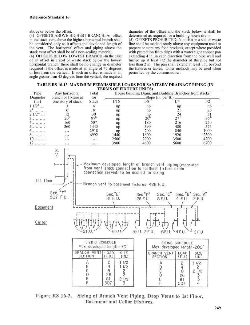
Reference Standard 16
249
above or below the offset.(3) OFFSETS ABOVE HIGHEST BRANCH.-An offsetin the stack vent above the highest horizontal branch shallbe considered only as it affects the developed length ofthe vent. The horizontal offset and piping above thestack vent offset shall be of a non-scaling material.(4) OFFSETS BELOW LOWEST BRANCH.-In the caseof an offset in a soil or waste stack below the lowesthorizontal branch, there shall be no change in diameterrequired if the offset is made at an angle of 45 degreesor less from the vertical. If such an offset is made at anangle greater than 45 degrees from the vertical, the required
diameter of the offset and the stack below it shall bedetermined as required for a building house drain.(5) OFFSETS PROHIBITED.-No offset in a soil or wasteline shall be made directly above any equipment used toprepare or store any food products, except where providedwith protection from drips with a water tight copper panextending 4 in. in each direction from the pipe wall andturned up at least 1/2 the diameter of the pipe but notless than 2 in. The pan shall extend at least 1 ft. beyondthe fixtures or tables. Other methods may be used whenpermitted by the commissioner.
TABLE RS 16-13 MAXIMUM PERMISSIBLE LOADS FOR SANITARY DRAINAGE PIPING (INTERMS OF FIXTURE UNITS)
House building Drain, and Building Branches from stacks6444444444Slope (in. per ft.) 44444444448
PipeDiameter
(in.)
Any horizontalbranch or fixture atone story of stack
Totalfor
Stack 1/16 1/8 1/4 1/21 1/2a .... 3 4 np np np np2 a …..…. 6 8 np np 21 262 1/2 a... . 12 30 np np 24 313………. 20b 97b np 20b 27 b 36 b
4………. 160 507 np 180 216 2505………. 360 1445 np 390 480 5756………. … 2918 np 700 840 10008………. … 6992 1440 1600 1920 230010……... … …. 2500 2900 3500 420012……... … …. 3900 4600 5600 6700
Reference Standard 16
250
Notes-a No water closets permitted.bNot over two water closets permitted.np = not permitted.
P108.11 Drip Pipes.-Drips from pump bases,air conditioning drips, and similar clear water drips maybe collected into a 1 in. pipe, and the pipe may be connectedto the inlet side of a floor drain trap. Piping undergroundshall be of brass or copper.
Section P109.0 Vent PipingP109.1 Size of Vents.-The nominal size of
vent piping including vent headers shall be determinedfrom its length and the total number of fixture unitsconnected thereto, as provided in Table RS 16-14. In nocase however, shall the nominal size be less than the following:(a) Individual vent.-1 1/2 in. or 1/2 the diameter of thedrainage pipe to which it is connected, whichever is greater.(b) Relief vent.-1 1/2 in. or 1/2 the diameter of the soil orwaste branch to which it is connected, whichever is greater.(c) Branch vents.-Branch vents connecting more thanone individual vent to a stack or stack-vent shall be in
accordance with Table RS 16-14. The branch vent sizeshall be based upon the number of fixture unitsconnected thereto, and the developed length of thebranch vent measured from its vent stack (or stack-vent) connection to the farthest fixture drain connectionserved by the branch vent. See Figure RS 16-2.(d) Vent stacks.-The developed length of a vent stackshall be measured from the base or point of connectionwith the attending soil or waste stack to the connectionwith a vent header or its termination above the roof.Stacks shall be sized in accordance with Table RS 16-14.
P109.2 Protection of Trap Seals.-The protectionof trap seals from siphonage or back pressure shall beaccomplished by the use of soil or waste stacks, vents,revents, back vents, continuous vents, or combinationsthereof, installed in accordance with the requirements ofthis code, so that at no time shall the trap-seal be subjectedto a pressure differential of more than 1 in. of water.
TABLE RS 16-14 SIZE OF VENT STACKS AND BRANCH VENTSDiameter of vent required (in.)
1 1/2 2 2 1/2 3 4 5 6 8 10Size of soil
(in.) orwaste stack
Fixtureunits
Connected Maximum developed length of vent (ft.)**1 1/2…….… 4 100 † .. .. .. .. .. .. ..2…………... 8 30 170 † .. .. .. .. .. ..2 1/2………. 30 15 70 175 † .. .. .. .. ..3…………... 97 6 24 89 250 † .. .. .. ..4…………... 507 * * 11 78 310 † .. .. ..5…………... 1445 * * * 16 110 380 † .. ..6…………... 2918 * * * * 34 143 380 † ..8…………... 6992 * * * * * 14 73 340 †10….……... … * * * * * * * * †Notes-*not permitted.**A 1 1/2 in. vent may be used for 6 or less fixture units for a developed length of 15 ft. from the fixture to header regardless of developed length limiting the header size.† unlimited
P109.3 Vent Stack and Stack Vents.-(a) Minimum size.-Any building in which a buildingdrain is installed shall have at least one 4 in. vent stack(or stack-vent) carried full size through the roof.(b) Vent stack required.-Every building in whichplumbing is installed shall have at least one 4 in. mainstack or stack-vent, which shall run undiminished insize and as directly as possible, from the building drainthrough to the outdoor air above the roof. A vent stackshall be installed in conjunction with each soil or wastestack in a building containing three or more branchintervals; however, one vent stack may serve not morethan two soil or waste stacks.(c) Connections at base and top.-All main vents orvent stacks shall connect full size at their base to thebuilding drain or to the soil or waste stack at or belowthe level of the lowest drainage connection to the soil orwaste stack. All vent stacks shall extend undiminished
in size above the roof, or shall be reconnected to a ventheader, or to the stack vent portion of the soil or wastestack, at least 6 in. above the flood level of the highestfixture connection discharging into the soil or waste stack. (d) Angle of offsets and connections.-Offsets in thestack vent portion of soil and waste stacks (above thehighest fixture drainage connection), offsets in ventstacks, and connections of vent stacks at the bottom to asoil or waste pipe or to the building house drain, shall bemade at an angle of at least 45 degrees to the horizontal.However, where provision is made to wash out the scaleabove the offset or where the entire piping above suchoffsets is of nonscaling type, the offset angle may bereduced, provided there is sufficient slope for condensationto drain back to soil or waste pipe connections.(e) Vent headers.-Where stack vents and vent stacksare connected into a vent header, such connections shallbe made at the tops of the stacks. The vent header shall
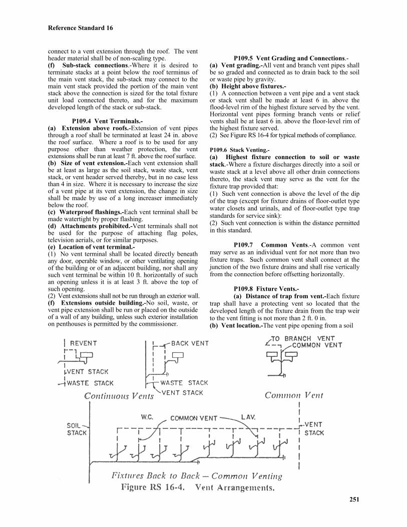
Reference Standard 16
251
connect to a vent extension through the roof. The ventheader material shall be of non-scaling type.(f) Sub-stack connections.-Where it is desired toterminate stacks at a point below the roof terminus ofthe main vent stack, the sub-stack may connect to themain vent stack provided the portion of the main ventstack above the connection is sized for the total fixtureunit load connected thereto, and for the maximumdeveloped length of the stack or sub-stack.
P109.4 Vent Terminals.-(a) Extension above roofs.-Extension of vent pipesthrough a roof shall be terminated at least 24 in. abovethe roof surface. Where a roof is to be used for anypurpose other than weather protection, the ventextensions shall be run at least 7 ft. above the roof surface.(b) Size of vent extension.-Each vent extension shallbe at least as large as the soil stack, waste stack, ventstack, or vent header served thereby, but in no case lessthan 4 in size. Where it is necessary to increase the sizeof a vent pipe at its vent extension, the change in sizeshall be made by use of a long increaser immediatelybelow the roof.(c) Waterproof flashings.-Each vent terminal shall bemade watertight by proper flashing.(d) Attachments prohibited.-Vent terminals shall notbe used for the purpose of attaching flag poles,television aerials, or for similar purposes.(e) Location of vent terminal.-(1) No vent terminal shall be located directly beneathany door, operable window, or other ventilating openingof the building or of an adjacent building, nor shall anysuch vent terminal be within 10 ft. horizontally of suchan opening unless it is at least 3 ft. above the top ofsuch opening.(2) Vent extensions shall not be run through an exterior wall.(f) Extensions outside building.-No soil, waste, orvent pipe extension shall be run or placed on the outsideof a wall of any building, unless such exterior installationon penthouses is permitted by the commissioner.
P109.5 Vent Grading and Connections.-(a) Vent grading.-All vent and branch vent pipes shallbe so graded and connected as to drain back to the soilor waste pipe by gravity.(b) Height above fixtures.-(1) A connection between a vent pipe and a vent stackor stack vent shall be made at least 6 in. above theflood-level rim of the highest fixture served by the vent.Horizontal vent pipes forming branch vents or reliefvents shall be at least 6 in. above the floor-level rim ofthe highest fixture served.(2) See Figure RS 16-4 for typical methods of compliance.
P109.6 Stack Venting.-(a) Highest fixture connection to soil or wastestack.-Where a fixture discharges directly into a soil orwaste stack at a level above all other drain connectionsthereto, the stack vent may serve as the vent for thefixture trap provided that:(1) Such vent connection is above the level of the dipof the trap (except for fixture drains of floor-outlet typewater closets and urinals, and of floor-outlet type trapstandards for service sink):(2) Such vent connection is within the distance permittedin this standard.
P109.7 Common Vents.-A common ventmay serve as an individual vent for not more than twofixture traps. Such common vent shall connect at thejunction of the two fixture drains and shall rise verticallyfrom the connection before offsetting horizontally.
P109.8 Fixture Vents.-(a) Distance of trap from vent.-Each fixture
trap shall have a protecting vent so located that thedeveloped length of the fixture drain from the trap weirto the vent fitting is not more than 2 ft. 0 in.(b) Vent location.-The vent pipe opening from a soil

Reference Standard 16
252
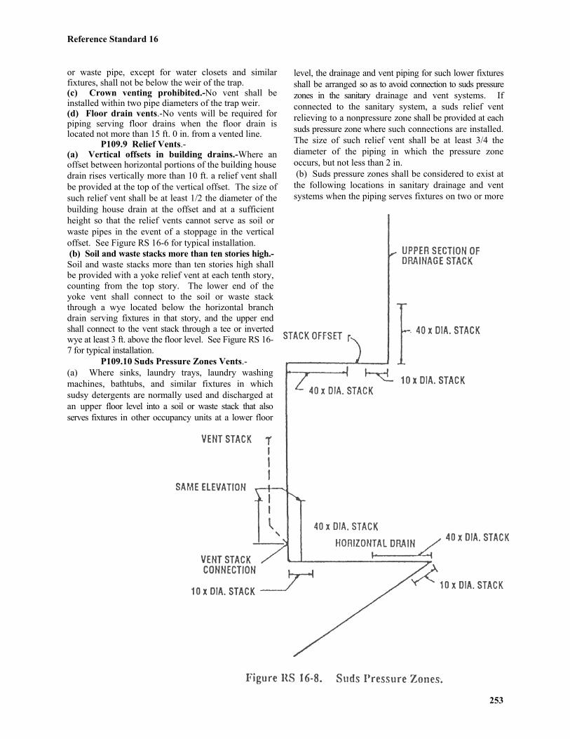
Reference Standard 16
253
or waste pipe, except for water closets and similarfixtures, shall not be below the weir of the trap.(c) Crown venting prohibited.-No vent shall beinstalled within two pipe diameters of the trap weir.(d) Floor drain vents.-No vents will be required forpiping serving floor drains when the floor drain islocated not more than 15 ft. 0 in. from a vented line.
P109.9 Relief Vents.-(a) Vertical offsets in building drains.-Where anoffset between horizontal portions of the building housedrain rises vertically more than 10 ft. a relief vent shallbe provided at the top of the vertical offset. The size ofsuch relief vent shall be at least 1/2 the diameter of thebuilding house drain at the offset and at a sufficientheight so that the relief vents cannot serve as soil orwaste pipes in the event of a stoppage in the verticaloffset. See Figure RS 16-6 for typical installation. (b) Soil and waste stacks more than ten stories high.-Soil and waste stacks more than ten stories high shallbe provided with a yoke relief vent at each tenth story,counting from the top story. The lower end of theyoke vent shall connect to the soil or waste stackthrough a wye located below the horizontal branchdrain serving fixtures in that story, and the upper endshall connect to the vent stack through a tee or invertedwye at least 3 ft. above the floor level. See Figure RS 16-7 for typical installation.
P109.10 Suds Pressure Zones Vents.-(a) Where sinks, laundry trays, laundry washingmachines, bathtubs, and similar fixtures in whichsudsy detergents are normally used and discharged atan upper floor level into a soil or waste stack that alsoserves fixtures in other occupancy units at a lower floor
level, the drainage and vent piping for such lower fixturesshall be arranged so as to avoid connection to suds pressurezones in the sanitary drainage and vent systems. Ifconnected to the sanitary system, a suds relief ventrelieving to a nonpressure zone shall be provided at eachsuds pressure zone where such connections are installed.The size of such relief vent shall be at least 3/4 thediameter of the piping in which the pressure zoneoccurs, but not less than 2 in. (b) Suds pressure zones shall be considered to exist atthe following locations in sanitary drainage and ventsystems when the piping serves fixtures on two or more

Reference Standard 16
254
floors that receive wastes that contain sudsy detergents.See Figure RS 16-8 for location of suds pressure zones. (1) In a soil or waste stack a zone shall be consideredto exist in the vertical portion within 40 stack diametersof the base fitting.(2) In the horizontal drain at the baseof a soil or waste stack a zone shall be considered toexist in the horizontal portion within ten stackdiameters of the base fitting. Where a 60 degree or 90degree fitting is installed in the horizontal drain, a zoneshall be considered to exist in the horizontal portionwithin 40 drain diameters upstream of and 10 draindiameters downstream of the fitting.(3) In a soil or waste stack offset of 60 degrees or 90degrees, a zone shall be considered to exist in thevertical portion of the stack within 40 stack diametersof the base fitting for the upper section of the stack. Thezone shall be considered to exist in the horizontal offsetwithin 10 stack diameters of such base fitting andwithin 40 stack diameters of the top fitting for the lowersection of the stack. (4) In a vent stack that has its base connected to a sudspressure zone in the sanitary drainage system, a zoneshall be considered to exist in the portion of the ventstack extending from its base connection up to thelowest branch vent fitting located above the level of thesuds pressure zone in the sanitary drainage system.
P109.11 Permitted Combination Waste andVent Systems.-A combination waste and vent pipingsystem, limited for use as a means of venting the traps offloor drains and laboratory sinks, shall be permitted inconjunction with horizontal branch waste piping of anindependent flammable oil waste system or acid wastesystems, and as described under indirect wastes andspecial wastes. See Figure RS 16-9 for typical installation.
Section P110.0 Storm Drainage PipingP110.1 Permits.-
(a) Permits for the installation of a building housestorm sewer from the street line to, and including thespur connection at the street sewer shall be obtained inaccordance with the requirements of the building code.Street sewer connections shall be made as provided inSection P108.2(a), (b), (c) and (d).
*P110.2 Disposal of Storm Water.-(a) Definitions.-As used in this section:(1) "Block" means a tract of land bounded by streets,public parks, railroad rights-of-way when located at orabove ground level but not including sidings or spurswithin a lot in the same ownership as the lot, airportboundaries, pierhead lines or shore lines, where nopierced lines have been established, or corporateboundary lines of New York city;

Reference Standard 16
255
(2) "Building combined sewer" means a building sewerintended to convey all types of wastewater, subject tocertain restrictions;(3) "Building sewer" means a sewer consisting of thepart of the horizontal piping of a drainage system thatextends from the end of a building house drain, asdefined in section P100.00 of reference standard RS-16of this code, to a street sewer or to another point ofdisposal. Building combined sewers and building stormsewers are types of building sewers;(4) "Building storm sewer" means that part of thehorizontal piping of a storm water drainage system thatextends from a building house storm drain, as definedin section P100.00 of reference standard RS-16 of thiscode, to a street storm sewer, a street combined seweror another point of disposal;(5) "Catch basin" means a storm water inlet connectedto a storm sewer or a combined sewer;(6) "Commissioner" means the commissioner of thedepartment of buildings or his or her designee;(7) "Development" means a tract of land which hasbeen subdivided into two or more lots, whether or notsuch tract has been developed as by the installation ofany utilities or the construction of any streets orbuildings or other structures;(8) "Impermeable soil" means soil of classes 1-65, 2-65, 3-65, 4-65, 5-65, 9-65, 10-65 or 11-65, as set forthin section 27-675 and table 11-2 of this code.Uncontrolled fill, as described in section 27-679 of thiscode, shall be considered impermeable soil;(9) "Impervious surfaces" means those areas of a lot ordevelopment covered by roofs, terraces, outside balconies,canopies, or paved surfaces such as driveways, sidewalks,courts, streets, or parking areas. A surface paved with anaccepted asphalt or other acceptable material which,after compaction, is not thicker than one and one-halfinches shall not be considered impervious, provided suchsurface will pass an amount of water equivalent to one-half inch of rainfall per hour and is underlaid by permeablesoil;(10) "Lot" means a portion or parcel of land consideredas a unit; a zoning lot;(11) "Owner" means a person in whom legal or equitabletitle to property or premises is vested, a mortgagee orvendee in possession of premises, an assignee of rents,a receiver of premises or a person listed as owner oragent for an owner on the records as to real propertyownership maintained by the bureau of city collectionsof the department of finance unless such person establishesthat such records are erroneous or, if claiming that he isan agent of the owner, furnishes the identity of the owner;(12) "Permeable soil" means soil at least five feet indepth of classes 6-65, 7-65, or 8-65, as set forth insection 27-675 and table 11-2 of this code, or porousmaterial as determined by percolation tests. Controlledfill, as described in section 27-679 of this code, shall beconsidered permeable soil;(13) "Person" means a natural person, company, partnership,corporation, association, governmental body or otherlegal entity, including any individual or entity acting ina representative capacity;
(14) "Private" means not public;(15) "Public" means owned by the city and intendedfor use by the public, subject to restrictions which thecity or agencies thereof may impose;(16) "Storm water" means rain water or surface water;(17) "Street combined sewer" means a street sewerwhich is intended to receive the discharge of all typesof wastewater, subject to certain restrictions, from oneor more building sewers and catch basins and to conveysuch wastewater to an intercepting sewer, a privatesewage disposal system or some other point of disposal; (18) "Street sewer" means a sewer located in the bedof a street or elsewhere which is intended to receive thedischarge of all or certain types of wastewater from oneor more building sewers and, in some cases, from catchbasins, and to convey such wastewater to points ofdisposal. Street combined sewers and street stormsewers are types of street sewers;(19) "Street storm sewer" means a street sewer whichis intended to receive the discharge of storm water fromone or more building storm sewers and catch basins andto convey such storm water to a point of disposal;(20) "Substantial horizontal enlargement" means (a) anincrease in the area of a lot covered by impervioussurfaces which exceeds twenty percent of the existingarea so covered, provided that the existing and enlargedareas so covered exceed one thousand square feet intotal, or (b) an increase in the area of a lot covered byimpervious surfaces which exceeds two hundred squarefeet, provided that the commissioner has previouslyapproved the discharge of storm water from a buildinglocated on such lot by means of splash blocks; and(21) "Tidal creek" means any creek where the level ofwater rises and falls with tidal action, or would do so ifnot impeded by artificial structures including but notlimited to tide gates. **(b) Disposal of storm water when public sewersare located in front of the property.-Where any newbuilding or other substantial horizontal enlargement isto be constructed on a lot and the departmentdetermines that a public street storm sewer or publicstreet combined sewer is located directly in front of anypoint of any boundary of such lot and that it would befeasible, pursuant to subdivision (j) of this section, todischarge storm water from such lot into such streetstorm sewer or street combined sewer, the owner ofsuch lot shall ensure that all storm water falling orcoming to rest on all impervious surfaces within suchlot will be discharged to such street storm sewer orstreet combined sewer. Such discharge shall be bymeans of building storm sewers or building combinedsewers, provided that no sewage shall be dischargedinto a public street storm sewer. If the department determinesthat such street storm sewer or street combined sewerhas partial capacity to receive the storm water dischargedfrom such lot, the remainder of such storm water shallbe discharged pursuant to subdivision (c) of this section. **(c) Disposal of storm water when public sewersare not located in front of the property.-Where anynew building or other substantial horizontal enlargement isto be constructed on a property and the department

Reference Standard 16
256
determines that no public street storm sewer or publicstreet combined sewer is located directly in front of anypoint of any boundary of such property, the owner ofsuch property shall ensure that all water falling or comingto rest on all impervious surfaces within such propertywill be discharged as follows:(1) Where one or more buildings is to be constructedon the subject property in any occupancy group otherthan occupancy group J, drainage of storm water shallbe by means of one building storm sewer or buildingcombined sewer for each such building, which sewershall be connected to a public street storm sewer orpublic street combined sewer. Such connection shall beby means of a house connection constructed in accordancewith section P108.2 of this reference standard, the rulesand regulations of the department and the applicablerules and regulations of the department of environmentalprotection, department of transportation and bureau offranchises. Provided, however, that no sewage shall bedischarged into a public street storm sewer. Providedfurther, that the provisions of this paragraph shall applyonly when
(A) the total area of impervious surfaces to beconstructed on the subject property equals or exceedstwenty thousand square feet; and
(B) the commissioner of environmentalprotection has determined that a public street stormsewer or public street combined sewer is located withintwo hundred feet of any point of any boundary of suchproperty, measured along a street, alley, right-of-way oreasement; and
(C) the commissioner of environmental protectiondetermines that it would be feasible, pursuant tosubdivision (j) of this section, to discharge storm waterin accordance with the provisions of this paragraph.(2) Where paragraph one of this subdivision does notapply, drainage of storm water shall be by means of:
(A) On-site disposal of storm water inaccordance with the provisions of section P110.13 ofthis reference standard; or
(B) Where a lot abuts a paved street whichcontains curbs and has been improved in accordancewith the requirements of the department of transportation,drainage of storm water to the boundary of such lotabutting such street. From such boundary, such stormwater may be discharged through an under-sidewalkdrain or drains onto such street, provided that catchbasins adequate to receive such storm water are locatedor installed in accordance with the requirements of thiscode and of the department of environmental protection.The means of drainage set forth in this subparagraphshall be used to discharge storm water from a lot onlywhen the commissioner, with the concurrence of thecommissioners of transportation and environmentalprotection, determines that such use is feasible; or
(C) Where a lot abuts any street, drainage ofstorm water by means of enclosed drainage pipes andbuilding storm sewers or building combined sewers tothe boundary of such lot abutting such street. From suchboundary, all such storm water, together with all stormwater falling or coming to rest on all streets and other
paved areas outside of such lot which are constructed oraltered for the primary purpose of improving vehicular orpedestrian access thereto, shall be conveyed by sewers,constructed in accordance with the requirements of subdivision(h) of this section and other requirements of the departmentand the department of environmental protection, to apublic street sewer. In no event shall sewage be dischargedinto a public street storm sewer. When necessary to complywith the requirements of this subparagraph, the owner ofsuch lot shall be responsible for installation of a controlledflow storm water system in accordance with the requirementsof section P110.6 of this reference standard; or
(D) In the case of any lot or development,drainage of storm water from the impervious surfacesof such lot or development by means of drainage pipes,culverts, paved swales, ditches or watercourses. Suchstorm water may be conveyed by such means across lotlines within a development and through under-sidewalkdrains within a lot or development to a boundary ofsuch lot or development. From such boundary, suchstorm water, together with all storm water falling orcoming to rest on all streets and other paved areasoutside of such lot or development constructed oraltered in connection with the construction of one ormore buildings on such lot or in such development forthe primary purpose of improving vehicular orpedestrian access thereto, shall be conveyed to one ofthe points of disposal set forth in subdivision (d) of thissection. The means of storm water disposal describedin this subparagraph may be utilized only if: (i) The owner or owners of the lot or developmentshall submit to the commissioner a comprehensivegrading and drainage plan for such development which, inthe commissioner's judgment, will satisfy the drainagerequirements set forth in this section. The commissionerof environmental protection and, if such plan providesfor drainage of storm water into a catch basin located ina public or private street, the commissioner of transportationshall concur in such judgement; and(ii) When the plan described in clause (i) of thissubparagraph provides for the drainage of storm waterfrom one lot in a development across other property insuch development, the owner or owners of suchdevelopment shall obtain an agreement between eachowner of property within such development from whichor across which such storm water will be drained andthe commissioner.* Such agreement shall bind eachsuch owner and his or her heirs, successors and assignsto properly maintain the storm water drainage system.Such agreement shall be filed in the office of the countyclerk in the county in which the development is located; or (E) Any means of drainage acceptable to thecommissioner, including any combination of the meansspecified in subparagraphs (A), (B), (C), an (D) above.Provided, however, that over-sidewalk drains shall notbe permitted. Provided, further, that the commissionershall consult with the commissioner of environmentalprotection or the commissioner of transportation, asappropriate, prior to approving any such combination ofmeans or any means of drainage not specified in this paragraph.*Language missing. So in original.
Reference Standard 16
257
(d) Points of discharge for storm water from a lot ordevelopment.-Storm water drained from a lot ordevelopment pursuant to subparagraph (D) of paragraphtwo of subdivision (c) of this section may be discharged into:(1) the New York harbor, or a point on a tidal creekacceptable to the commissioner of environmental protectionas an adequate storm water outlet; provided that onlybuilding storm sewers and, if necessary, street stormsewers are constructed and that no sewage is dischargedat such a point of disposal, and provided further thatsuch outlets shall only be used in compliance withapplicable provisions of law; or(2) a public street storm sewer or public street combinedsewer, regardless of its distance from the property, towhich the commissioner of environmental protectiondetermines that discharge of storm water is feasible,pursuant to subdivision (j) of this section, provided thatno sewage shall be discharged into a street storm sewer; or(3) an existing private street storm sewer or private streetcombined sewer to which the commissioner of environmentalprotection determines that discharge of storm water isfeasible, pursuant to subdivision (j) of this section,provided that such street sewer connects with a publicstreet sewer or, if it is a private storm sewer, dischargesdirectly into the New York harbor, or into a point on atidal creek acceptable to the commissioner of environmentalprotection as an adequate storm water outlet, in accordancewith applicable provisions of law, and provided furtherthat no sewage shall be discharged into a street storm sewer.(e) Areaway drains.-Areaway drains may be connectedto the footing or subsoil drainage system when permittedby the commissioner. Garages installed in a manner thatwould permit the flow of storm water from surroundingsurfaces to enter the garages shall be provided with agravity drain, or a sump and pump connected to a stormsewer, or other means of disposal as provided in thisreference standard.(f) Drains carrying clear water.-All drains carryingclear water, i.e., air conditioning drips, pump drips,cooling water, etc., may discharge into the storm waterdrainage system through an indirect waste connectiondischarging into a trapped funnel or drain.(g) Drainage system design.-The storm water drainagesystem shall be designed, constructed and maintained toguard against fouling, deposit of solids and cloggingand shall be provided with adequate cleanouts soarranged that the pipes may be readily cleaned.(h) Maximum required capacity for street stormsewers or street combined sewers required by this section.-The commissioner of environmental protection may requirean owner of a lot or a development who is required bythis section to construct street storm sewers or streetcombined sewers to construct such sewers with a capacitynot to exceed twenty-five percent above and beyond thecapacity which the commissioner of environmental protectiondetermines is needed for the disposal of storm waterfalling or coming to rest on such property together withstorm water falling or coming to rest on all streets andother paved areas outside of such property which areconstructed or altered in connection with the constructionof a building or other substantial horizontal enlargement
on such property for the primary purpose of improvingvehicular or pedestrian access thereto. The departmentof environmental protection reserves the right toconstruct catch basins connected to such sewers at thecost and expense of the city, to alleviate flooding orponding conditions, provided that the commissioner ofenvironmental protection determines that the capacityof such sewers shall not be exceeded.(i) Repair of defects in catch basins and sewersrequired.-Any owner of property who causes any catchbasin or any sewer which shall lie outside of suchproperty to be constructed pursuant to subdivision (c) ofthis section shall cause all defects in such catch basin orsewer and all faults in its installation to be repaired for aperiod of two years after it has been installed, immediatelyafter the commissioner of environmental protectionorders such person to do so.(j) Feasibility of discharging storm water into astreet storm sewer or a street combined sewer.-Thecommissioner of environmental protection shall determinethat the discharge of storm water into a street storm seweror a street combined sewer pursuant to this section isfeasible if he finds that:(1) the sewer is of adequate capacity to receive all suchstorm water or would be adequate to receive it if theowner of property installed controlled flow storm watersystems, in accordance with the requirements of sectionP110.6 of reference standard RS-16 of this code, torestrict the maximum anticipated storm water flow to alevel set by the commissioner of environmental protection;(2) the sewer is in adequate physical condition toreceive such storm water;(3) no physical obstacle which would make conveyanceof storm water to the sewer impracticable exists betweenthe sewer and the boundaries of the development or lotfrom which such storm water shall be discharged;(4) conveyance of such storm water to the sewer is notimpracticable because of the elevation of the sewer inrelation to the development or lot from which suchstorm water shall be discharged;(5) the sewer is located in the same drainage area as allor most of the development or lot from which suchstorm water shall be discharged; and(6) no other factor reasonably related to the conveyanceof such storm water from such development or lot to thesewer would make the discharge of such storm waterinto the sewer impracticable or undesirable as a propermeans of storm water disposal.(k) Time by which construction of the storm waterdrainage system required by this section shall be completed.-The storm water drainage system for property requiredby this section shall be completed prior to the issuanceof a certificate of occupancy by the department of buildingsfor, and actual occupancy of, the building or othersubstantial horizontal enlargement in connection withwhich such storm water drainage system is being constructed. (l) Contractual obligations of the city not abrogated.-The provisions of this section shall not be construed toabrogate or contravene any contractual obligation of thecity to construct storm water drainage systems or partsthereof. The requirements of subdivisions (b), (c), (d)

Reference Standard 16
258
and (i) of this section shall be inapplicable to an ownerof property insofar as they relate to any constructionwork required to be performed by the city pursuant tosuch a contractual obligation.(m) Remedies for non-functioning systems.-If thecommissioner determines that a system of storm waterdisposal which has been previously approved under theprovisions of this code or of previous codes is no longerproviding adequate drainage of storm water from a lotor development, he or she shall order repair of suchsystem as required by section 27-127 of this code; or if,in the judgment of the commissioner, repair of suchsystem is not sufficient to ensure adequate drainage ofstorm water from such lot or development, he or sheshall order that one of the methods of storm waterdisposal set forth in subdivisions (b) and (c) of thissection shall be used to provide such drainage. Thecommissioner may apply to the board of standards andappeals for modification of the certificate of occupancyof any building constructed on such lot or developmentto require the use of such method.*Local Law 103-1989; Local Law 7-1974** Local Law 65-1996
P110.3 Storm Water Drainage to SanitarySewer Prohibited.-Storm water shall not be drainedinto sanitary sewers intended for sewage only.
P110.4 Size of Storm Drains and Leaders.-(a) Building storm drain.-The size of the buildingstorm drain or any of its horizontal branches, except thebranch serving a single roof drain, having a slope of 1/2in. per ft. or less shall be based upon the maximum
projected roof or paved area to be handled according toTable RS 16-17.(b) Storm sewers.-Where more than one buildingstorm drain discharges into a private sewer within theproperty line, the sewer may be sized on a rationalsewer design basis and the slope of the sewer shall bepredicated on the size selected; but in no case shall theslope be less than that required to produce a velocity inthe sewer of at least 3 fps.(c) Vertical leaders.-Vertical leaders, including thebranch to a single roof drain, shall be sized on themaximum projected roof area in accordance with TableRS 16-18. The equivalent diameter of square leadermay be taken as the diameter of that circle which maybe inscribed within the cross-sectional area of theleader. The equivalent diameter of a rectangular leadershall be taken as the number of standard size circularleaders, having a diameter equal to the short dimensionof the rectangular leader that can be fitted within therectangular leader. For example, the equivalent diameterof a 4 in. by 3 in. rectangular leader is 1-1/3 3 in. circularleaders.(d) Roof gutters.-The size of a semicircular gutter shall bebased on the maximum projected roof area according to TableRS 16-19.(e) Combined drains and sewers.-To compute thesize of a combined drain or sewer, the fixture units andthe square feet of drained area shall be converted totheir equivalent square footage or drainage area fromTable RS 16-20 and either Table RS 16-13 or RS 16-17shall be used to determine the pipe size required. Forintermediate values, interpolation shall be used.
TABLE RS 16-17 SIZE OF HORIZONTAL STORM DRAINSMaximum Projected Roof Area for Various Slopes of Drains
Diameter of Drain 1/8 in. Slope 1/4 in. Slope 1/2 in. Slope (in.) Square Feet Square Feet Square Feet2 250 350 5002 1/2 357 505 7143 690 930 1,3204 1,500 2,120 3,0005 2,700 3,800 5,3206 4,300 6,100 8,7008 9,300 13,000 18,400
10 16,600 23,500 33,000 12 26,700 37,500 53,000 15 47,600 67,000 95,000
TABLE RS 16-18 SIZE OF VERTICAL LEADERSDiameter of Leader or Conductor (in.) gpm. Maximum Projected Roof Area (sq. ft.)
2 22.6 4332 1/2 39.6 7793 66.6 1,2784 143 2,7455 261 4,9926 423 8,1218 911 17,49110 1,652 31,718
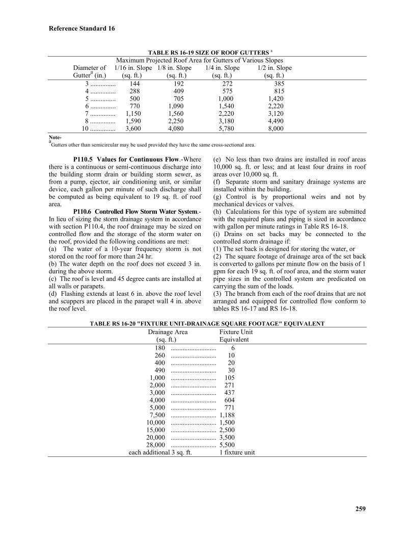
Reference Standard 16
259
TABLE RS 16-19 SIZE OF ROOF GUTTERS a
Maximum Projected Roof Area for Gutters of Various SlopesDiameter of 1/16 in. Slope 1/8 in. Slope 1/4 in. Slope 1/2 in. Slope
Guttera (in.) (sq. ft.) (sq. ft.) (sq. ft.) (sq. ft.)3 ............... 144 192 272 3854 ............... 288 409 575 8155 ............... 500 705 1,000 1,4206 ............... 770 1,090 1,540 2,220
7 ............... 1,150 1,560 2,220 3,120 8 ............... 1,590 2,250 3,180 4,490 10 ............... 3,600 4,080 5,780 8,000
Note-aGutters other than semicircular may be used provided they have the same cross-sectional area.
P110.5 Values for Continuous Flow.-Wherethere is a continuous or semi-continuous discharge intothe building storm drain or building storm sewer, asfrom a pump, ejector, air conditioning unit, or similardevice, each gallon per minute of such discharge shallbe computed as being equivalent to 19 sq. ft. of roofarea.
P110.6 Controlled Flow Storm Water System.-In lieu of sizing the storm drainage system in accordancewith section P110.4, the roof drainage may be sized oncontrolled flow and the storage of the storm water onthe roof, provided the following conditions are met:(a) The water of a 10-year frequency storm is notstored on the roof for more than 24 hr.(b) The water depth on the roof does not exceed 3 in.during the above storm.(c) The roof is level and 45 degree cants are installed atall walls or parapets.(d) Flashing extends at least 6 in. above the roof leveland scuppers are placed in the parapet wall 4 in. abovethe roof level.
(e) No less than two drains are installed in roof areas10,000 sq. ft. or less; and at least four drains in roofareas over 10,000 sq. ft.(f) Separate storm and sanitary drainage systems areinstalled within the building.(g) Control is by proportional weirs and not bymechanical devices or valves.(h) Calculations for this type of system are submittedwith the required plans and piping is sized in accordancewith gallon per minute ratings in Table RS 16-18.(i) Drains on set backs may be connected to thecontrolled storm drainage if:(1) The set back is designed for storing the water, or(2) The square footage of drainage area of the set backis converted to gallons per minute flow on the basis of 1gpm for each 19 sq. ft. of roof area, and the storm waterpipe sizes in the controlled system are predicated oncarrying the sum of the loads.(3) The branch from each of the roof drains that are notarranged and equipped for controlled flow conform totables RS 16-17 and RS 16-18.
TABLE RS 16-20 "FIXTURE UNIT-DRAINAGE SQUARE FOOTAGE" EQUIVALENT Drainage Area Fixture Unit (sq. ft.) Equivalent 180 ........................... 6 260 ........................... 10 400 ........................... 20 490 ........................... 30 1,000 ........................... 105 2,000 ........................... 271 3,000 ........................... 437
4,000 ........................... 604 5,000 ........................... 771 7,500 ........................... 1,18810,000 ........................... 1,50015,000 ........................... 2,50020,000 ........................... 3,50028,000 ........................... 5,500
each additional 3 sq. ft. 1 fixture unit
Reference Standard 16
260
P110.7 Traps on Storm Drains and Leaders.-(a) Where required.-Leaders and storm drains whenconnected to a combined sewer shall be trapped. Nofresh air inlet will be required for building storm drains.Intake and exhaust plenum drains connected to a stormdrain shall be trapped. One trap may serve more thanone drain if any drain served by the trap is not morethan 15 ft. from the trap. (b) Where not required.-No traps shall be requiredfor storm water drains that are connected to a buildinghouse drain or building house sewer carrying stormwater exclusively.(c) Trap equivalent.-A hooded catch basin located withinthe street line shall be the equivalent of a building orhouse trap for the connection to a street combined sewer.(d) Method of installation.-Individual storm water trapsshall be installed on the storm water drain branch servingeach conductor, or a single trap shall be installed in themain storm drain just before its connection with thecombined building sewer, main drain, or public sewer.
P110.8 Leaders or Storm Water Piping.-(a) Improper use of storm water piping.-Leader or stormwater pipes shall not be used as soil, waste, or vent pipes.(b) Protection of rain water conductors.-Rain waterconductors installed along alleyways, driveways, orother locations where they may be exposed to damageshall be protected by metal guards, be recessed into thewall, or be constructed of pipe.(c) Method of combining storm with sanitary drainage.-The sanitary and storm-drainage system of a buildingshall be entirely separate except that where a combinedstreet sewer is deemed available, the building storm drainmay be connected, in the same horizontal plane through atrap and a single fitting to the combined drain or sewer atleast 40 pipe diameters downstream from any soil stack.
P110.9 Roof Drain Strainers.-(a) General use.-All roof areas, except those drainingto hanging gutters, shall be equipped with roof drainshaving strainers extending at least 4 in. above thesurface of the roof immediately adjacent to the roofdrain. Strainers shall have an available inlet area aboveroof level at least 1 1/2 times the area of the conductoror leader to which the drain is connected.(b) Flat decks.-Roof drain strainers for use on suchdecks, parking decks, and similar areas, normallyserviced and maintained, may be of the flat surface typeand set flush with the deck, and shall have an availableinlet area at least twice the area of the conductor or
leader to which the drain is connected.
P110.10 Roof Drain Flashings Required.-The connection between roofs and roof drains that passthrough the roof and into the interior of the buildingshall be made watertight by the use of proper flashingmaterial.
P110.11 Expansion Joints Required.-Expansion joints or sleeves shall be provided wheretemperature variation or physical conditions may causeexcessive stress or movement in the drain or piping.
P110.12 Sanitary and Storm Sewers.-Whereseparate systems of sanitary drainage and storm waterdrainage are installed in the same property, the stormand sanitary building sewers and drains may be laidside by side in the same trench.
* P110.13 On-Site Disposal.-(a) Storm water, as defined in subdivision (a) ofsection P110.2 of this reference standard, falling onareaways 25 sq. ft. or less in area may be leached intothe ground within the areaway if the ground water is atleast 2 ft. below the elevation of the areaway.(b) An owner of a lot, as defined in subdivision (a) ofsection P110.2 of this reference standard, may disposeof all storm water falling or coming to rest within suchlot on-sight only as permitted by the provisions ofsubdivision (c) of section P110.2 of this reference standard.(c) Drywells shall be the only method of on-sitedisposal of storm water permitted, except as provided insubdivision (a) of this section or unless an alternatemethod of on-site disposal is approved by the commissionerwith the concurrence of the commissioner of environmentalprotection or the commissioner of transportation, asappropriate, pursuant to subparagraph (E) of paragraphtwo of subdivision (c) of section P110.2 of thisreference standard. Drywells shall be constructed inaccordance with the following provisions: (1) Except as provided in paragraph two of thissubdivision, the size of a drywell shall be predicated ona soil percolation test performed in accordance with theprovisions of section P113.9 of this reference standard,and shall be based upon rainfall of two inches in atwenty-four-hour period on all impervious surfaceswhere a site is underlaid by permeable soil. Where asite is underlaid by impermeable soil, the size of adrywell shall be based upon rainfall of two inches in atwenty-four hour period over the entire site.

Reference Standard 16
261
(2) If a drywell is used in combination with one ormore other methods of storm water disposal pursuant tosubparagraph (e) of paragraph two of subdivision (c) ofsection P110.2 of this reference standard, the size ofsuch drywell shall be determined by the percentage ofthe storm water such drywell shall dispose.
(3) The construction of drywells shall be subject tocontrolled inspection.(4) Drywells shall be located at least five feet from alllot lines and ten feet from all foundations or wallsexisting on the date of application for a building permitor proposed under the application to construct the drywell.
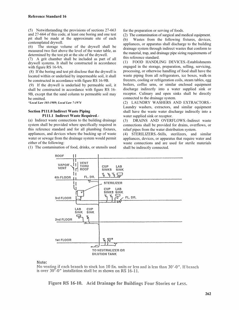
Reference Standard 16
262
(5) Notwithstanding the provisions of sections 27-663and 27-664 of this code, at least one boring and one testpit shall be made at the approximate site of eachcontemplated drywell.(6) The storage volume of the drywell shall bemeasured two feet above the level of the water table, asdetermined by the test pit at the site of the drywell.(7) A grit chamber shall be included as part of alldrywell systems. It shall be constructed in accordancewith figure RS 16-9A. (8) If the boring and test pit disclose that the drywell islocated within or underlaid by impermeable soil, it shallbe constructed in accordance with figure RS 16-9B. (9) If the drywell is underlaid by permeable soil, itshall be constructed in accordance with figure RS 16-9B, except that the sand column to permeable soil maybe omitted.*Local Law 103-1989; Local Law 7-1974
Section P111.0 Indirect Waste PipingP111.1 Indirect Waste Required.-
(a) Indirect waste connections to the building drainagesystem shall be provided where specifically required inthis reference standard and for all plumbing fixtures,appliances, and devices where the backing up of wastewater or sewage from the drainage system would permiteither of the following:(1) The contamination of food, drinks, or utensils used
for the preparation or serving of foods.(2) The contamination of surgical and medical equipment.(b) Wastes from the following fixtures, devices,appliances, or apparatus shall discharge to the buildingdrainage system through indirect wastes that conform tothe material, trap, and drainage pipe sizing requirements ofthis reference standard.(1) FOOD HANDLING DEVICES.-Establishmentsengaged in the storage, preparation, selling, servicing,processing, or otherwise handling of food shall have thewaste piping from all refrigerators, ice boxes, walk-infreezers, cooling or refrigeration coils, steam tables, eggboilers, coffee urns, or similar enclosed equipmentdischarge indirectly into a water supplied sink orreceptor. Culinary and open sinks shall be directlyconnected to the drainage system.(2) LAUNDRY WASHERS AND EXTRACTORS.-Laundry washers, extractors, and similar equipmentshall have the waste water discharge indirectly into awater supplied sink or receptor.(3) DRAINS AND OVERFLOWS.-Indirect wasteconnections shall be provided for drains, overflows, orrelief pipes from the water distribution system.(4) STERILIZERS.-Stills, sterilizers, and similarappliances, devices, or apparatus that require water andwaste connections and are used for sterile materialsshall be indirectly connected.

Reference Standard 16
263
(5) DRIPS OR DRAINAGE OUTLETS.-Appliances,devices, or apparatus not regularly classed as plumbingfixtures, but which have drips or drainage outlets, maybe drained by indirect waste pipes.(6) WASTE DISCHARGING CLEAR WATER.-Expansion tanks, cooling jackets, sprinkler systems, orsimilar devices that waste clear water only shalldischarge into the building storm or sanitary drainagesystem through an indirect waste.(7) SWIMMING POOLS.-Pipes carrying waste waterfrom swimming or wading pools, including pooldrainage, backwash from filters, or water from scumgutter drains, shall be installed as indirect wastes.Circulation pumps may be utilized to lift waste waterwhen the waste line is below the sewer grade. (8) PRESSURE TANKS, BOILERS AND RELIEFVALVES.-The drains from pressure tanks, boilers,relief valves, and similar equipment shall be connectedto the drainage system through indirect wastes.(9) REFRIGERATORS.-Each indirect waste pipe froma refrigerator or equipment used for storage of foodshall discharge into a receptacle through an air breakand, in no instance, shall the indirect waste be trappedahead of the air break. The maximum developed lengthof piping between the outlet and the air break shall be 2 ft.(c) The air break for the indirect waste shall beprovided by terminating the open end of the pipe atleast 1 in. above the flood level rim of the receivingfixture or receptacle.
P111.2 Common Indirect Wastes.-The wastesfrom drinking fountains, bar sinks, soda fountains, andsimilar fixtures may be connected to a common indirectwaste stack or header, provided each fixture connectedthereto is properly trapped.
P111.3 Venting.-No vents need be providedfor the traps of fixtures that are connected to indirectwaste piping. Indirect wastes exceeding 100 ft. in developedlength, except for indirect wastes from show caserefrigerators, which shall not exceed 25 ft. in developedlength, shall be extended through the roof or outsidewall independent of vents for the regular sanitary system,and they shall terminate as required for sanitary vents.
P111.4 Sizing.-Indirect wastes shall be sizedin accordance with the requirements of the direct wastesystem on the basis of fixture units only. Developedlength shall not apply in determining pipe size.
P111.5 Receptors or Sumps.-(a) Installation.-(1) Waste receptors or sumps serving indirect wastepipes shall not be installed in any toilet room, unlessinstalled in a separate compartment, nor in any inaccessibleor unventilated space.(2) All plumbing receptors receiving the discharge of
indirect waste pipes shall be of such shape and capacityas to prevent splashing or flooding.(3) Standpipe receptors for automatic clothes washersshall be installed in one of the following ways:a. The standpipe receptor shall be individually trappedand vented, the trap shall not be installed below thefloor, and the standpipe shall extend not more than 30in. nor less than 18 in. above the trap weir.b. The standpipe receptor shall be installed in thegrating of a floor drain that shall be tapped to receive thestandpipe, and the floor drain size shall be predicated oneither the discharge rate of the automatic clothes washeror the floor area to be drained, whichever is greater.(b) Strainers and baskets. Every indirect waste receptorshall be equipped with a removable basket or a beehivestrainer not less than 4 in. in height. Floor drains receivingan indirect waste discharge need not have dome strainers.(c) Domestic or culinary fixtures prohibited as receptors.No plumbing fixture that is used for domestic or culinarypurposes shall be used to receive the discharge of anindirect waste pipe, except that in a dwelling a kitchensink may be used as the receptor for a dishwasher, and alaundry tray may be used as the receptor for a clotheswashing machine.
P111.6 Condensers and Sumps.-No steampipe shall connect to any part of a drainage or plumbingsystem, nor shall any water above 150 degrees F bedischarged into any part of the drainage system, exceptthat 180 degrees water may be discharged as permittedherein from a commercial dishwasher or laundry. Suchpipes, except from the dishwasher, shall be connectedby discharging into an indirect waste receptor connected tothe drainage system.
Section P112.0 Special and MiscellaneousWaste Piping
P112.1 Industrial Wastes.-Industrial wastesfrom abattoirs, chemical plants, metal platers, dyeworks, and similar wastes may not be discharged to asewer system without an industrial waste permit of thedepartment of public works, except as hereinafter provided.
P112.2 Chemical Wastes.-(a) No corrosive liquids, acids, strong alkalis, or otherchemicals that might destroy or damage the drain, soil,waste, or vent pipes, or that might create noxious ordangerous fumes, shall be discharged into the regulardrainage systems until brought within permittedconcentrations by treatment.(b) Such chemicals shall discharge through anindependent sanitary drainage system to a dilution orneutralizing device as described in section P105.0 orthrough some other means of disposal designed by anarchitect or engineer, subject to the approval of thecommissioner and of any other agency or agencies

Reference Standard 16
264
having jurisdiction.(c) Chemical waste and vent piping shall be of materialsresistant to the corrosive action of chemical fumes inaccordance with section P102.4.(d) The size of the vent and drainage piping shall meetthe requirements for sanitary vent and drainage systemsin sections P108.0 and P109.0.(e) All traps in an acid waste system shall have a deep seal.(f) The acid drainage system shall consist of a wasteand a vent stack. In a building where acid drainagesystems are provided to serve fixtures, drains, and/orequipment on four floors or less and have no horizontalbranch from the waste stack exceeding 30 ft. developedlength to the farthest fixture, the waste stack can serveas a wet vent and no branch venting shall be required.See Figure RS 16-10 for typical installation. (g) Acid dilution or neutralization sumps may belocated directly adjacent to, or beneath, each acid sink orfixture. The discharge from each individual acid sumpshall connect to the sanitary drainage system and thevent shall be treated in the same manner as a sanitary vent.(h) Where a common acid neutralization sump forseveral fixtures or stacks is used, it shall be located at
the lowest story above the house drain. A separate aciddilution sump may be used for fixtures on the first floorand below, and the neutralized effluent shall be lifted fromthe acid dilution sump to the gravity drainage system bypumping. The drain line at the inlet to dilution sumpshall be provided with a relief vent at least 2 in. indiameter or 1/2 the diameter of inlet pipe, whichever isgreater. The vent shall terminate in the outside air abovethe roof or connect to an acid system vent stack or stack vent.(i) Each drainage pipe that extends more than 30 ft.from the stack or has more than ten fixture unitsdischarging into it shall be provided with a ventconnection from the vent stack or stack vent to aconnection in the drain line installed between the lasttwo fixtures on the drain line and each 30 ft. increment.Also, a relief vent shall be installed in the horizontalbranch waste within 4 ft. of the stack. See Figure RS16-11 for typical installation.(j) Fixtures such as floor drains, receptors receiving theindirect waste from sterilizers, stills, and drains fromother laboratory equipment within the laboratory areamay be connected to the acid drainage system, if thefixtures, excluding floor drains, are provided withindividual vents, and all of the piping connecting thesefixtures of acid resistant material, or when permitted by
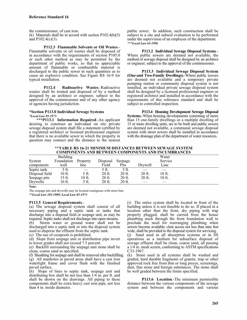
Reference Standard 16
265
the commissioner, of cast iron.(k) Materials shall be in accord with section P102.4(b)(5)and P102.4(c)(3).
P112.3 Flammable Solvents or Oil Wastes.-Flammable solvents or oil wastes shall be disposed ofin accordance with the requirements of section P105.0or such other method as may be permitted by thedepartment of public works, so that no appreciableamount of flammable or combustible material isdischarged to the public sewer in such quantities as tocause an explosive condition. See Figure RS 16-9 fortypical installation.
P112.4 Radioactive Wastes.-Radioactivewastes shall be treated and disposed of by a methoddesigned by an architect or engineer, subject to theapproval of the commissioner and of any other agencyor agencies having jurisdiction.
*Section P113.0 Individual Sewage Systems*Local Law 85-1973
***P113.1 Information Required.-An applicantdesiring to construct an individual on site privatesewage disposal system shall file a statement certified bya registered architect or licensed professional engineerthat there is no available sewer to which the property inquestion may connect and the distance to the nearest
public sewer. In addition, such construction shall besubject to a site and subsoil evaluation to be performedunder the supervision of an employee of the department.***Local Law 65-1996
P113.2 Individual Sewage Disposal Systems.-Where public sewers are deemed not available, themethod of sewage disposal shall be designed by an architector engineer, subject to the approval of the commissioner.
P113.3 Individual Sewage Disposal System(One-and Two-Family Dwellings).-Where public sewersare deemed not available and a temporary privatepumping station or community disposal system is notinstalled, an individual private sewage disposal systemshall be designed by a licensed professional engineer orregistered architect and installed in accordance with therequirements of this reference standard and shall besubject to controlled inspection.
P113.4 Housing Development Sewage DisposalSystems.-When housing developments consisting of morethan 15 one-family dwellings or a multiple dwelling of15 or more dwelling units, are to be built and public sewersare deemed not available, a communal sewage disposalsystem with street sewers shall be installed in accordancewith the drainage plan of the department of water resources.
**TABLE RS 16-21 MINIMUM DISTANCES BETWEEN SEWAGE SYSTEMCOMPONENTS AND BETWEEN COMPONENTS AND INCUMBRANCESBuilding Water
System Foundation Property Disposal Seepage Servicecomponents wall line Field Pits Drywell LineSeptic tank 5 ft. — 5 ft. 5 ft. — —Disposal field 10 ft. 5 ft. 20 ft. 20 ft. 20 ft. 10 ft.Seepage pits 15 ft. 10 ft. 20 ft. 20 ft. 20 ft. 10 ft.Drywells 10 ft. 5 ft. 20 ft. 20 ft. — —Note-The seepage pits and drywells may be located contiguous with street line.**Local Law 103-1989; Local Law 85-1973
P113.5 General Requirements.-(a) The sewage disposal system shall consist of allnecessary piping and a septic tank or tanks thatdischarge into a disposal field or seepage unit, as may berequired. Septic tanks shall not discharge into open streams.(b) Storm water or ground water shall not bedischarged into a septic tank or into the disposal systemused to disperse the effluent from the septic tank.(c) The use of cesspools is prohibited.(d) Slope from seepage unit or distribution pipe invertto lower grades shall not exceed 7.5 percent.(e) Backfill surrounding the seepage unit stone shall beclean, coarse sand as specified.(f) Sheathing for seepage unit shall be removed after backfilling.(g) All manholes in paved areas shall have a cast ironwatertight frame and cover flush with the finishedpaved surface.(h) Slope of lines to septic tank, seepage unit anddistributing box shall be not less than 1/4 in. per ft. andshall be shown on the drawings. All piping to thesecomponents shall be extra heavy cast iron pipe, not lessthan 4 in. inside diameter.
(i) The entire system shall be located in front of thebuilding unless it is not feasible to do so. If placed in alocation other than the front, dry piping with trapproperly plugged, shall be carried from the houseplumbing stack through the front foundation wall topreclude the need for rearranging plumbing whensewers become available; clear access not less than nine feetwide, shall be provided to the disposal system for servicing.(j) Sand used in all absorption systems or in filloperations as a medium for subsurface disposal ofsewage effluent shall be clean, coarse sand, all passinga 1/4 in. mesh screen, conforming to ASTM specificationsC33-1967.(k) Stone used in all systems shall be washed andgraded, hard durable fragments of granite, trap or otherapproved rock free from thin or long pieces, screenings,dust, fine stone and foreign substances. The stone shallbe well graded between the limits specified.
P113.6 Location.-The minimum permissibledistance between the various components of the sewagesystem and between the components and various

Reference Standard 16
266
encumbrances are given in Table RS 16-21. Allcomponents shall be located within the property line ofthe premises for which the system is installed.
P113.7 Septic Tanks.-(a) Construction.-Septic tanks shall be constructed of material not subjectto excessive corrosion or decay and shall be madewatertight. Manhole covers and roof shall be designedfor a live load of at least 150 psf. Concrete coverswhen used, shall be reinforced and at least 4 in. thick.Metal septic tanks shall conform to United StatesCommercial Standard 177-62.*(b) Manholes.-(1) The septic tank shall have one manhole situatedover the inlet and one over the outlet of the tank.Manholes shall be at least 20 in. square or 24 in. indiameter. The top of the manhole cover shall extend towithin 12 in. of final grade to provide easy access forinspection and cleaning. If the septic tank is placeddeep in the ground, a chimney or riser shall be providedto raise the manhole cover to the required distancebelow grade. No person other than a licensed masterplumber or a person engaged in sewer services shallremove or open the manhole cover of any septic tankunless otherwise authorized during an emergency by anofficer or employee of a city agency.(2) For purposes of this subdivision, "person engagedin sewer services" shall be defined as one who renderssewer services, including but not limited to installing,altering, repairing, cleaning and pumping sewers, septic
tanks and cesspools, as a part of one’s regular businessor employment.*Local Law 21-1981(c) Capacity.-(1) Minimum rated capacity of septic tanks shall be inaccordance with Table RS 16-22, and shall be predicatedupon the 24-hr. sewage flow under normal conditions,plus an allowance of approximately 20 percent forsludge accumulation.(2) In a tank of more than one compartment, the inletcompartment shall have a capacity of at least two-thirdsof the minimum required tank capacity prescribed inTable RS 16-22.(d) Design.-The concrete tank shall have a watersurface at the flow line that is rectangular in plan withthe length at least twice the width but no more thanthree times the width (Figure 16-12A). For steel tanksuse 5 ft. diameter (Figure 16-12B).
** Figure RS 16-12A Typical Concrete Septic Tank**Local Law 85-1973
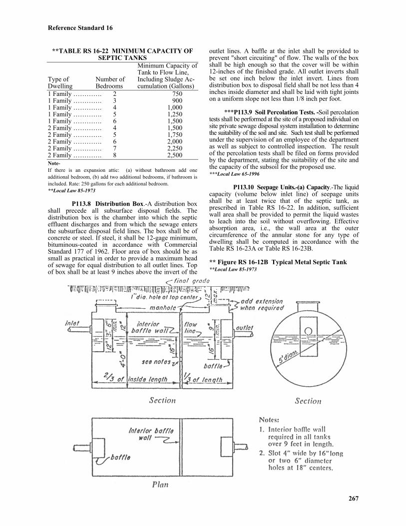
Reference Standard 16
267
**TABLE RS 16-22 MINIMUM CAPACITY OFSEPTIC TANKS
Minimum Capacity ofTank to Flow Line,
Type of Number of Including Sludge Ac-Dwelling Bedrooms cumulation (Gallons)1 Family …………. 2 7501 Family …………. 3 9001 Family …………. 4 1,0001 Family …………. 5 1,2501 Family …………. 6 1,5002 Family …………. 4 1,5002 Family …………. 5 1,7502 Family …………. 6 2,0002 Family …………. 7 2,2502 Family …………. 8 2,500Note-If there is an expansion attic: (a) without bathroom add oneadditional bedroom, (b) add two additional bedrooms, if bathroom isincluded. Rate: 250 gallons for each additional bedroom.**Local Law 85-1973
P113.8 Distribution Box.-A distribution boxshall precede all subsurface disposal fields. Thedistribution box is the chamber into which the septiceffluent discharges and from which the sewage entersthe subsurface disposal field lines. The box shall be ofconcrete or steel. If steel, it shall be 12-gage minimum,bituminous-coated in accordance with CommercialStandard 177 of 1962. Floor area of box should be assmall as practical in order to provide a maximum headof sewage for equal distribution to all outlet lines. Topof box shall be at least 9 inches above the invert of the
outlet lines. A baffle at the inlet shall be provided toprevent "short circuiting" of flow. The walls of the boxshall be high enough so that the cover will be within12-inches of the finished grade. All outlet inverts shallbe set one inch below the inlet invert. Lines fromdistribution box to disposal field shall be not less than 4inches inside diameter and shall be laid with tight jointson a uniform slope not less than 1/8 inch per foot.
***P113.9 Soil Percolation Tests. -Soil percolationtests shall be performed at the site of a proposed individual onsite private sewage disposal system installation to determinethe suitability of the soil and site. Such test shall be performedunder the supervision of an employee of the departmentas well as subject to controlled inspection. The resultof the percolation tests shall be filed on forms providedby the department, stating the suitability of the site andthe capacity of the subsoil for the proposed use.***Local Law 65-1996
P113.10 Seepage Units.-(a) Capacity.-The liquidcapacity (volume below inlet line) of seepage unitsshall be at least twice that of the septic tank, asprescribed in Table RS 16-22. In addition, sufficientwall area shall be provided to permit the liquid wastesto leach into the soil without overflowing. Effectiveabsorption area, i.e., the wall area at the outercircumference of the annular stone for any type ofdwelling shall be computed in accordance with theTable RS 16-23A or Table RS 16-23B.
** Figure RS 16-12B Typical Metal Septic Tank**Local Law 85-1973

Reference Standard 16
268
**TABLE RS 16-23A DESIGN DATA FOR ABSORPTIVE CAPACITYOF DISPOSAL FIELD AND SEEPAGE PITSa
Effluent Allowance Rate of Seepage Unit in gallons per square foot of effective absorptive area per day Percolation RatePercolation Test rate in Disposal Field minutes for water to Trenches Seepage Pits fall 1 inch (bottom of trenches) (wall area)2 or less 3.2 4.35 2.4 3.210 1.7 2.330 0.8 1.160 (not recommended) 0.4 0.6Over 60 (not suitable) Obtain special approval of the commissioner.
(Use special design by an architect or engineer, subject to the approval of the commissioner.)
a For one- or two-family dwellings table RS 16-23B shall be used.Notes-Volume of sewage to be disposed of should be equal to the 24 hr. sewage flow.No portion of the field shall be installed under any pavement or any area where there will be vehicular traffic or parking.**Local Law 85-1973
**TABLE RS 16-23B DESIGN DATA FOR ABSORPTIVE CAPACITYOF DISPOSAL FIELD AND SEEPAGE PITS
Minimum Capacity of Type of Number of Field and/or ofDwelling Bedrooms Pit to Flow Line1 Family....................... 2 7501 Family....................... 3 9001 Family....................... 4 1,0001 Family....................... 5 1,2501 Family....................... 6 1,5002 Family....................... 4 1,5002 Family....................... 5 1,7502 Family....................... 6 2,0002 Family....................... 7 2,2502 Family....................... 8 2,500
Notes-Add 250 gallons for each additional bedroom. To compute peripheral wall area in sq. ft. for gravel envelope of pits, divide above minimumcapacity by 4.3.To compute area required for disposal field in sq. ft. divide above minimum required capacity by 1.15.**Local Law 85-1973

Reference Standard 16
269
(b) Construction.-The seepage unit shall be structurallysound. The piping from the septic tank to the unit shallhave tight joints. The general construction arrangementshall be in accordance with Figure RS 16-13A or RS 16-13B.
** Figure RS 16-13A Absorption Type System**Local Law 85-1973
** Figure RS 16-13B Absorption Type**Local Law 85-1973
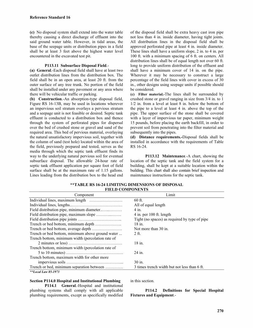
Reference Standard 16
270
(c) No disposal system shall extend into the water tablethereby causing a direct discharge of effluent into thesaid ground water table. However, in tidal areas, thebase of the seepage units or distribution pipes in a fieldshall be at least 3 feet above the highest water levelencountered in the excavated test pit.
P113.11 Subsurface Disposal Field.-(a) General.-Each disposal field shall have at least twooutlet distribution lines from the distribution box. Thefield shall be in an open area, at least 20 ft. from theouter surface of any tree trunk. No portion of the fieldshall be installed under any pavement or any area wherethere will be vehicular traffic or parking.(b) Construction.-An absorption-type disposal field,Figure RS 16-13B, may be used in locations whereveran impervious soil stratum overlays a pervious stratumand a seepage unit is not feasible or desired. Septic tankeffluent is conducted to a distribution box and thencethrough the system of perforated pipes for dispersalover the bed of crushed stone or gravel and sand of therequired area. This bed of pervious material, overlayingthe natural unsatisfactory impervious soil, together withthe column of sand (test hole) located within the area ofthe field, previously prepared and tested, serves as themedia through which the septic tank effluent finds itsway to the underlying natural pervious soil for eventualsubsurface disposal. The allowable 24-hour rate ofseptic tank effluent application per square foot of fieldsurface shall be at the maximum rate of 1.15 gallons.Lines leading from the distribution box to the head end
of the disposal field shall be extra heavy cast iron pipenot less than 4 in. inside diameter, having tight joints.All distribution lines in the disposal field shall beapproved perforated pipe at least 4 in. inside diameter.These lines shall have a uniform slope, 2 in. to 4 in. per100 ft. with a minimum spacing of 6 ft. on centers. Alldistribution lines shall be of equal length not over 60 ft.long to provide uniform distribution of the effluent andshall have a minimum cover of 14 in. on the pipe.Wherever it may be necessary to construct a largepercentage of the field lines with cover in excess of 30in., other designs using seepage units if possible shouldbe considered.(c) Filter material.-The lines shall be surrounded bycrushed stone or gravel ranging in size from 3/4 in. to 11/2 in. from a level at least 8 in. below the bottom ofthe pipe to a level at least 4 in. above the top of thepipe. The upper surface of the stone shall be coveredwith a layer of impervious tar paper, minimum weight15 pounds, before placing the earth backfill, in order toprevent soil from penetrating into the filter material andsubsequently into the pipes.(d) Distance requirements.-Disposal fields shall beinstalled in accordance with the requirements of TableRS 16-24.
P113.12 Maintenance.-A chart, showing thelocation of the septic tank and the field system for abuilding, shall be kept at a suitable location within thebuilding. This chart shall also contain brief inspection andmaintenance instructions for the septic tank.
**TABLE RS 16-24 LIMITING DIMENSIONS OF DISPOSALFIELD COMPONENTS
Component LimitIndividual lines, maximum length …………………… 60 ft.Individual lines, lengths...……………………………… All of equal lengthField distribution pipe, minimum diameter..…...……… 4 in.Field distribution pipe, maximum slope ………...……. 4 in. per 100 ft. lengthField distribution pipe joints ………………………….. Tight (no spaces) as required by type of pipeTrench or bed bottom, minimum depth ………………. 18 in.Trench or bed bottom, average depth …………………. Not more than 30 in.Trench or bed bottom, minimum above ground water ... 2 ft.Trench bottom, minimum width (percolation rate of 2 minutes or less) ………………………………… 18 in.Trench bottom, minimum width (percolation rate of 5 to 10 minutes) ………………………..…………. 24 in.Trench bottom, maximum width for other more impervious soils …………………………………... 30 in.Trench or bed, minimum separation between …………. 3 times trench width but not less than 6 ft.**Local Law 85-1973
Section P114.0 Hospital and Institutional PlumbingP114.1 General.-Hospital and institutional
plumbing systems shall comply with all applicableplumbing requirements, except as specifically modified
in this section.
P114.2 Definitions for Special HospitalFixtures and Equipment.-

Reference Standard 16
271
ASPIRATOR.-A fitting or device that issupplied with water or other fluid under positivepressure. The water or other fluid passes through anintegral orifice, or constriction, causing a vacuum.Aspirators are often referred to as "suction" apparatus,and are similar in operation to an ejector fitting.
AUTOPSY TABLE.-A fixture or table usedfor the post-mortem examination of a body. (SeeSection P107.0 for method of connecting water supply.)
BEDPAN HOPPER (CLINIC SINK).-Afixture used to flush the contents of bedpans and meetthe design requirements of Section P114.3(a).
BEDPAN STEAMER.-A fixture used forsanitizing bedpans or urinal bottles by direct applicationof steam.
BEDPAN WASHER.-A fixture designed towash bedpans and to flush the contents into the sanitarydrainage system. It may also be used for sanitizingbedpans and urinals with steam or hot water.
BEDPAN WASHER DEVICE.-A deviceused for cleansing bedpans. It is supplied with hotand/or cold water, and is located adjacent to a watercloset or clinic sink or installed in the discharge pipingof the flush valve.
BEDPAN WASHER VENT.-A local vent thatis a vertical pipe to which connections are made fromthe fixture side of traps and through which vapor and/orfoul air may be removed from the bedpan washer.
CLINIC SINK.-See "Bedpan Hopper."STERILIZER, BOILING TYPE.-A fixture
(nonpressure vessel) used for boiling instruments,utensils, and/or other equipment for the purpose ofdisinfection. Some devices are portable, others areconnected to the plumbing system.
STERILIZER, PRESSURE (AUTOCLAVE).-A fixture (pressure vessel) designed to use steam underpressure for sterilizing.
STERILIZER, PRESSURE (INSTRUMENTWASHER-STERILIZER TYPE).-A fixture (pressurevessel) designed to both wash and sterilize instrumentsduring the operating cycle of the fixture.
STERILIZER VENT.-A separate pipe orstack, indirectly connected to the building drainagesystem at the lower terminal. The pipe or stack receivesthe vapors from nonpressure sterilizers or the exhaustvapors from pressure sterilizers and conducts the vaporsdirectly to the outer air. (Sometimes called a vapor, asteam, an atmosphere or an exhaust vent.)
STERILIZER, WATER.-A fixture (pressurevessel) designed for sterilizing water and storing thissterile water.
STILL.-A device used for distilling liquids.
P114.3 Requirements for Special HospitalFixtures and Equipment.-Bedpan hoppers (clinicsinks), bedpan washers, and similar fixtures and
equipment shall be provided for disposal of bedpancontents and cleansing and disinfecting bedpans. Allsuch fixtures and equipment shall be subject to thefollowing requirements:(a) Bedpan hoppers (clinic sinks).-Such fixtures shallhave an integral trap in which the upper portion of avisible trap seal provides a water surface. The fixtureshall be designed so as to permit complete removal ofthe contents by siphonic and/or blow-out action, and toreseal the trap in a single flushing operation. A flushingrim shall provide water to cleanse the interior surface.The fixtures shall have flushing and cleansing characteristicssimilar to a water closet.(b) Prohibited use of clinic sinks and service sinks.-A clinic sink shall not be used as a janitor's servicesink. A janitors service sink shall not be used for thedisposal of urine, fecal matter, or other human wastes.(c) Special requirement for ice manufacture andstorage.-No machines for manufacturing ice, or anydevice for handling or storing ice, shall be located in aroom containing a bedpan hopper, clinic sink, bedpanwasher, or similar fixture. Machines for manufacturingice, or devices for handling or storing ice intended foreither human consumption or packs, shall be located ina clean utility room, a floor pantry, a diet kitchen, or inother similar locations.(d) Sterilizers.-(1) DESCALING PROHIBITED.-The interior of watersterilizers, stills, or similar equipment shall not bedescaled or otherwise treated by acid or other chemicalsolutions while the equipment is connected to the waterand/or drainage system. (2) STANDARD.-New pressure sterilizers andpressure type instrument washer-sterilizers hereafterinstalled shall conform to ASME boiler and pressurevessel code, 1962, section VIII and shall bear a dataplate clearly visible at all times indicating conformity tosuch standards.(3) STERILIZER PIPING.-All sterilizer piping and/ordevices necessary for the operation of sterilizers shallbe accessible for inspection and maintenance.a. Steam supply.-Steam supplies to sterilizers, includingthose connected by pipes from overhead mains or branches,shall be drained to prevent any excess moisture fromreaching the sterilizer. The condensate drainage fromthe steam supply shall be discharged by gravity.b. Condenser.-Pressure sterilizers shall be equippedwith a means for condensing exhaust steam vapors.c. Gas fired equipment.-Gas fired equipment or apparatusrequiring either water or drainage connections, or both,shall comply with the requirements of this reference standardand the applicable provisions of the building code.
P114.4 Plumbing in Mental Hospitals.-Special consideration shall be given to the design andinstallation of plumbing fixtures in mental hospitals. No
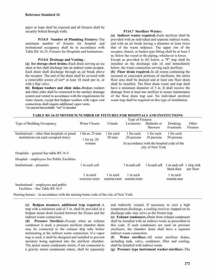
Reference Standard 16
272
pipes or traps shall be exposed and all fixtures shall besecurely bolted through walls.
P114.5 Number of Plumbing Fixtures.-Theminimum number of fixtures for hospital andinstitutional occupancy shall be in accordance withTable RS 16-25, Fixtures for Hospitals and Institutions.
P114.6 Drainage and Venting.-(a) Ice storage chest drains.-Each drain serving an icechest or box shall discharge into an indirect waste receptor.Each drain shall discharge through an air break abovethe receptor. The end of the drain shall be covered witha removable screen of not* at least 10 mesh per in. orwith a flap valve.(b) Bedpan washers and clinic sinks.-Bedpan washersand clinic sinks shall be connected to the sanitary drainagesystem and vented in accordance with the requirements forwater closets, except that bedpan washers with vapor ventconnections shall require additional vapor vents.*As enacted but probably “net” is intended.
P114.7 Sterilizer Wastes.-(a) Indirect wastes required.-Each sterilizer shall beprovided with an individual and separate indirect waste,and with an air break having a diameter at least twicethat of the waste tailpiece. The upper rim of thereceptor, funnel, or basket type fitting shall be at least 2in. below the vessel or the piping, whichever is lower.Except as provided in (b) below, a "P" trap shall beinstalled on the discharge side of, and immediatelybelow, the waste connection serving each sterilizer.(b) Floor drain required.-In all rooms containing therecessed or concealed portions of sterilizers, the entirefloor area shall be drained and at least one floor drainshall be installed. The floor drain waste and trap shallhave a minimum diameter of 3 in. It shall receive thedrainage from at least one sterilizer to assure maintenanceof the floor drain trap seal. No individual sterilizerwaste trap shall be required on this type of installation.
TABLE RS 16-25 MINIMUM NUMBER OF FIXTURES FOR HOSPITALS AND INSTITUTIONSType of Fixtures
Type of Building Occupancy Water Closets Urinals Lavatories Bathtubs orShowers
DrinkingFountains
OtherFixtures
1 for each20 persons
1 for each10 persons
1 for each50 persons
Institutional—other than hospitals or penalinstitutions (on each occupied story)
1 for ea. 25 men
1 for ea. 20women
1 for each50 men
In accordance with the hospital code of thecity of New York
Hospitals – general See table RS 16-5
Hospital – employees See Public Facilities
Institutional – prisoners 1 in each cell 1 in each cell 1 in each cell 1 on each cellblock floor
1 slop sinkper floor
1 in eachexercise room
1 in eachexercise room
1 in eachexercise room
1 in eachexercise area
Institutional – employees and publicFacilities – See Table RS 16-5
Nursing homes – in accordance with the nursing home code of the city of New York.
(c) Bedpan steamers, additional trap required.-Atrap with a minimum seal of 3 in. shall be provided in abedpan steam drain located between the fixture and theindirect waste connection.(d) Pressure Sterilizer.-Except when an exhaustcondenser is used, a pressure sterilizer chamber drainmay be connected to the exhaust drip tube beforeterminating at the indirect waste connection. If a vaportrap is used, it shall be designed and installed to preventmoisture being aspirated into the sterilizer chamber.The jacket steam condensate return, if not connected toa gravity steam condensate return, shall be separately
and indirectly wasted. If necessary to cool a hightemperature discharge, a cooling receiver, trapped on itsdischarge side, may serve as the fixture trap.(e) Exhaust condensers.-Drain from exhaust condensersshall be installed with an indirect waste as prescribed inthis code. If such condensers are used on pressuresterilizers, the chamber drain shall have a separateindirect waste connection.(f) Water sterilizer.-All water sterilizer drains,including tank, valve, condenser, filter and cooling,shall be installed with indirect waste.(g) Pressure type instrument washer-sterilizer.-The

Reference Standard 16
273
pressure type instrument washer-sterilizer chamberdrain and overflow may be interconnected. They mayalso be interconnected with the condenser. The indirectwaste shall comply with the provisions of this referencestandard.
P114.8 Vapor Vents.-(a) Vent material.-Material for sterilizer, vapor, andexhaust vents shall be as required by Section P102.4.(b) Vent connections prohibited.-Connections betweenvapor vents serving bedpan washers, sterilizing apparatus,and/or normal sanitary systems, are prohibited. Only onetype of apparatus shall be served by a given type vent.(c) Bedpan Vents and stacks.-(1) BEDPAN WASHERS.-Bedpan washers shall bevented to the outer atmosphere above the roof by meansof bedpan vents. The vent for a bedpan washer shall beat least a 2 in. diameter pipe. A bedpan vent serving asingle bedpan washer may drain to the fixture served.(2) MULTIPLE INSTALLATIONS.-Where bedpanwashers are located above each other on more than one
floor, a bedpan vent stack may be installed to receivethe bedpan vent on the various floors. The connectionsbetween a bedpan washer vent and a bedpan vent stackshall be made by using tee or tee-type sanitary patterndrainage fittings, installed in an upright position. SeeTable RS 16-26 for vent sizing.(3) TRAP REQUIRED.-The bottom of the bedpan ventstack, except when serving only one bedpan washer, shallbe drained by means of a trapped connection dischargingindirectly into the plumbing sanitary drainage system.The trap and waste shall be at least 2 in. in size.(4) TRAP SEAL MAINTENANCE.-A water supply ofat least 1/4 in. tubing shall be taken from the flushsupply of each bedpan washer on the discharge orfixture side of the vacuum breaker, trapped to form atleast a 3 in. seal, and connected to the local vent oneach floor. The water supply shall be so installed as toprovide a supply of water to the local vent stack forcleansing and drain trap seal maintenance each time abedpan washer is flushed.
TABLE RS 16-26STACK SIZES FOR BEDPAN STEAMERS AND BOILING TYPESTERILIZERS AND NUMBER OF CONNECTIONS PERMITTED
No. of Connections Permitted Connection Size (in.)
Stack Size (in.) 1 1/2 21 1/2 ................................................... 1 or 02 ......................................................... 2 or 12 ......................................................... 1 and 13 ......................................................... 4 or 23 ......................................................... 2 and 24 ......................................................... 8 or 44 ......................................................... 4 and 4
(d) Pressure sterilizer vent and stacks.-(1) CONNECTIONS.-In multiple installations of pressureand nonpressure sterilizers, vent connections to the sterilizer(vapor) vent stack shall be made by means of invertedtype fittings.(2) DRAINAGE.-The connection between sterilizervent and/or exhaust openings and the sterilizer ventstack shall be designed and installed to drain to thefunnel or basket-type waste fitting. In multiple installations,the sterilizer vent stack shall be drained separately tothe lowest sterilizer funnel or basket-type waste fittingor receptor.
P114.9 Sizing of Sterilizer Vent Stack.-(a) Bedpan steamers.-The minimum diameter of asterilizer vent serving a bedpan steamer shall be 1 1/2in. Multiple installations shall be sized according toTable RS 16-26.(b) Boiler type sterilizer.-The minimum diameter of a
sterilizer vent stack shall be 2 in. when serving a utensilsterilizer, and 1 1/2 in. when serving an instrumentsterilizer. Combinations of boiling type sterilizer ventconnections shall be based on Table RS 16-26.(c) Pressure sterilizers.-The minimum diameter ofsterilizer vent stacks or the vertical stack vent from asingle unit shall be 2 in. minimum. Stacks servingcombinations of pressure sterilizer exhaust connectionsshall be sized according to Table RS 16-27.(d) Pressure type instrument washer-sterilizer.-Theminimum diameter of a sterilizer vent stack serving aninstrument washer-sterilizer shall be 2 in.(e) Roof penetration.-Vent shall be increased in sizeand extended through the roof in accordance withsanitary venting requirements.
P114.10 Water Supply.-(a) Services.-All hospitals shall be provided with atleast two water service connections. Whenever more

Reference Standard 16
274
than one street main is available, the connections shallbe made to different street mains.(b) Water supply protection.-The installation of thewater supply shall meet all the requirements prescribedin Section P107.0, except as hereinafter provided. (SeeTable RS 16-28.)
(c) Hot water supply protection.-Hot water supply topatients' showers, therapeutic equipment, and continuousbaths shall be provided with control valves automaticallyregulating the temperature of the water supply to thefixture. The valve shall fail in a closed position when thetempered water supply to the fixture exceeds 110 degrees F.
TABLE RS 16-27 STACK SIZES FOR PRESSURE STERILIZERS ANDNUMBER OF CONNECTIONS PERMITTED
No. of Connections PermittedStack Size 644444444Connection Size (in.)444444448 (in.) 3/4 1 1 1/4 1 1/2 1 1/2 3 or 2 or 1 1 1/2 2 and 1 2 6 or 3 or 2 or 1 2 3 and 2 2 2 and 1 and 1 2 1 and 1 and 1 3 15 or 1 or 5 or 3 3 1 and 2 and 2 3 1 and 5 and 1
TABLE RS 16-28 FIXTURE WATER SUPPLY PROTECTIONa Fixtures Type of Protection Remarks
Aspirators Separate water system ______Bedpan Washers Vacuum breaker Washer Hose Vacuum breaker Locate 5 ft. above floorBoiler type sterilizer Air gap Not less than twice the
effective opening ofthe water supply
Exhaust condenser Vacuum breaker ______Pressure type instrument washer-sterilizer Vacuum breaker ______Pressure type sterilizer Vacuum breaker ______Note-a Where vacuum breakers are used, they shall be installed after the last control valve. See section P107.2 for requirements for other fixtures.
P114.11 Vacuum systems.-(a) Aspirators, water.-The use of water aspirators isprohibited.(b) Bottle systems.-Vacuum systems intended forcollecting, removing and/or disposing of blood, pus,and/or other fluids shall be protected by bottles(furnished as secondary equipment) installed near theoutlet. Each vacuum outlet station shall be equipped soas to prevent fluids other than air from entering thevacuum piping systems.(c) Central system equipment.-The collecting and/orcontrol tanks in central systems shall be provided withdrains for cleaning the tanks. The exhausts fromvacuum pumps used in connection with a vacuumsystem shall discharge separately to the outdoor airabove the roof or at such other locations as may bepermitted by the Commissioner. The exhaust discharge
shall, in no case, be located so as to cause a hazard topublic safety, health or welfare.
*P114.12 Oxygen and Nitrous Oxide Systems.-Whereoxygen and nitrous oxide systems are installed, thepiping, outlets, manifolds, manifold rooms, and storagerooms shall be installed in accordance with the requirementsof ANSI/NFiPA 99-1987 Standard for Health CareFacilities, as modified and ANSI/NFiPA 50-1985 BulkOxygen Systems at Consumer Sites. The alarms for thesystems shall comply with Reference Standard RS 17-3and the requirements of the fire department.ANSI/NFiPA 99-1987 shall be subject to the followingmodifications:Section 4-3.1.4 Amend the initial sentence to read as follows:The central supply system shall be a system of cylindersand necessary supply equipment assemblied as described
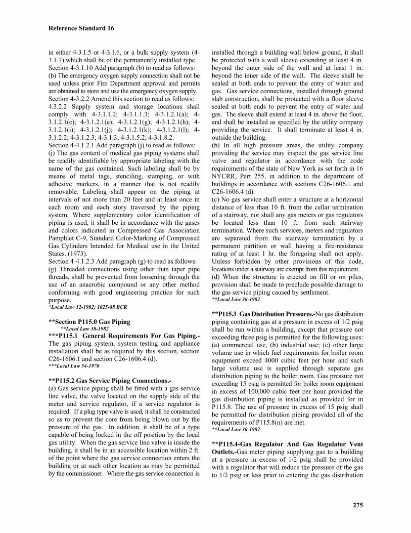
Reference Standard 16
275
in either 4-3.1.5 or 4-3.1.6, or a bulk supply system (4-3.1.7) which shall be of the permanently installed type.Section 4-3.1.10 Add paragraph (b) to read as follows:(b) The emergency oxygen supply connection shall not beused unless prior Fire Department approval and permitsare obtained to store and use the emergency oxygen supply.Section 4-3.2.2 Amend this section to read as follows:4.3.2.2 Supply system and storage locations shallcomply with 4-3.1.1.2; 4-3.1.1.3; 4-3.1.2.1(a); 4-3.1.2.1(c); 4-3.1.2.1(e); 4-3.1.2.1(g); 4-3.1.2.1(h); 4-3.1.2.1(i); 4-3.1.2.1(j); 4-3.1.2.1(k); 4-3.1.2.1(l); 4-3.1.2.2; 4-3.1.2.3; 4-3.1.3; 4-3.1.5.2; 4-3.1.8.2.Section 4-4.1.2.1 Add paragraph (j) to read as follows:(j) The gas content of medical gas piping systems shallbe readily identifiable by appropriate labeling with thename of the gas contained. Such labeling shall be bymeans of metal tags, stenciling, stamping, or withadhesive markers, in a manner that is not readilyremovable. Labeling shall appear on the piping atintervals of not more than 20 feet and at least once ineach room and each story traversed by the pipingsystem. Where supplementary color identification ofpiping is used, it shall be in accordance with the gasesand colors indicated in Compressed Gas AssociationPamphlet C-9, Standard Color-Marking of CompressedGas Cylinders Intended for Medical use in the UnitedStates. (1973).Section 4-4.1.2.3 Add paragraph (g) to read as follows:(g) Threaded connections using other than taper pipethreads, shall be prevented from loosening through theuse of an anaerobic compound or any other methodconforming with good engineering practice for suchpurpose.*Local Law 12-1982; 1025-88 BCR
**Section P115.0 Gas Piping**Local Law 30-1982
***P115.1 General Requirements For Gas Piping.-The gas piping system, system testing and applianceinstallation shall be as required by this section, sectionC26-1606.1 and section C26-1606.4 (d).***Local Law 54-1970
**P115.2 Gas Service Piping Connections.-(a) Gas service piping shall be fitted with a gas serviceline valve, the valve located on the supply side of themeter and service regulator, if a service regulator isrequired. If a plug type valve is used, it shall be constructedso as to prevent the core from being blown out by thepressure of the gas. In addition, it shall be of a typecapable of being locked in the off position by the localgas utility. When the gas service line valve is inside thebuilding, it shall be in an accessible location within 2 ft.of the point where the gas service connection enters thebuilding or at such other location as may be permittedby the commissioner. Where the gas service connection is
installed through a building wall below ground, it shallbe protected with a wall sleeve extending at least 4 in.beyond the outer side of the wall and at least 1 in.beyond the inner side of the wall. The sleeve shall besealed at both ends to prevent the entry of water andgas. Gas service connections, installed through groundslab construction, shall be protected with a floor sleevesealed at both ends to prevent the entry of water andgas. The sleeve shall extend at least 4 in. above the floor,and shall be installed as specified by the utility companyproviding the service. It shall terminate at least 4 in.outside the building.(b) In all high pressure areas, the utility companyproviding the service may inspect the gas service linevalve and regulator in accordance with the coderequirements of the state of New York as set forth in 16NYCRR, Part 255, in addition to the department ofbuildings in accordance with sections C26-1606.1 andC26-1606.4 (d).(c) No gas service shall enter a structure at a horizontaldistance of less than 10 ft. from the cellar terminationof a stairway, nor shall any gas meters or gas regulatorsbe located less than 10 ft. from such stairwaytermination. Where such services, meters and regulatorsare separated from the stairway termination by apermanent partition or wall having a fire-resistancerating of at least 1 hr. the foregoing shall not apply.Unless forbidden by other provisions of this code,locations under a stairway are exempt from this requirement.(d) When the structure is erected on fill or on piles,provision shall be made to preclude possible damage tothe gas service piping caused by settlement.**Local Law 30-1982
**P115.3 Gas Distribution Pressures.-No gas distributionpiping containing gas at a pressure in excess of 1/2 psigshall be run within a building, except that pressure notexceeding three psig is permitted for the following uses:(a) commercial use, (b) industrial use; (c) other largevolume use in which fuel requirements for boiler roomequipment exceed 4000 cubic feet per hour and suchlarge volume use is supplied through separate gasdistribution piping to the boiler room. Gas pressure notexceeding 15 psig is permitted for boiler room equipmentin excess of 100,000 cubic feet per hour provided thegas distribution piping is installed as provided for inP115.8. The use of pressure in excess of 15 psig shallbe permitted for distribution piping provided all of therequirements of P115.8(n) are met.**Local Law 30-1982
**P115.4-Gas Regulator And Gas Regulator VentOutlets.-Gas meter piping supplying gas to a buildingat a pressure in excess of 1/2 psig shall be providedwith a regulator that will reduce the pressure of the gasto 1/2 psig or less prior to entering the gas distribution
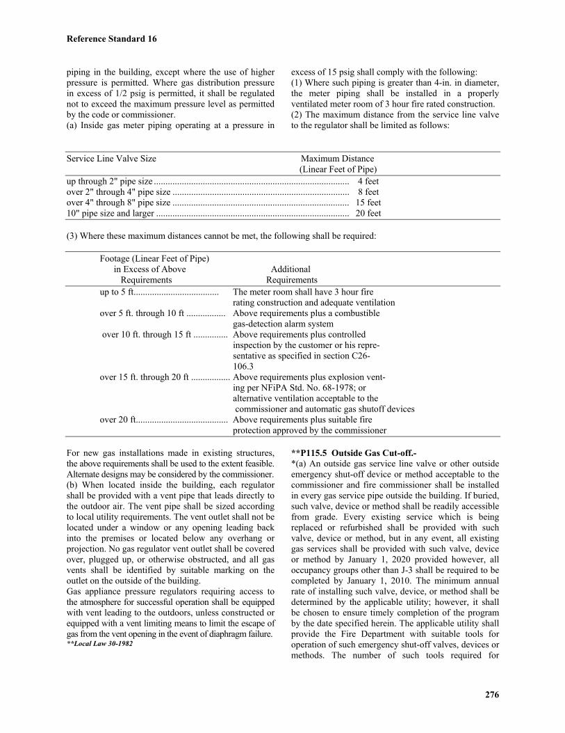
Reference Standard 16
276
piping in the building, except where the use of higherpressure is permitted. Where gas distribution pressurein excess of 1/2 psig is permitted, it shall be regulatednot to exceed the maximum pressure level as permittedby the code or commissioner.(a) Inside gas meter piping operating at a pressure in
excess of 15 psig shall comply with the following:(1) Where such piping is greater than 4-in. in diameter,the meter piping shall be installed in a properlyventilated meter room of 3 hour fire rated construction.(2) The maximum distance from the service line valveto the regulator shall be limited as follows:
Service Line Valve Size Maximum Distance (Linear Feet of Pipe)up through 2" pipe size .................................................................................... 4 feetover 2" through 4" pipe size ............................................................................ 8 feetover 4" through 8" pipe size ............................................................................ 15 feet10" pipe size and larger ................................................................................... 20 feet
(3) Where these maximum distances cannot be met, the following shall be required:
Footage (Linear Feet of Pipe) in Excess of Above Additional Requirements Requirementsup to 5 ft..................................... The meter room shall have 3 hour fire
rating construction and adequate ventilationover 5 ft. through 10 ft ................. Above requirements plus a combustible
gas-detection alarm system over 10 ft. through 15 ft ............... Above requirements plus controlled
inspection by the customer or his repre-sentative as specified in section C26-106.3
over 15 ft. through 20 ft ................. Above requirements plus explosion vent-ing per NFiPA Std. No. 68-1978; or alternative ventilation acceptable to the commissioner and automatic gas shutoff devices
over 20 ft........................................ Above requirements plus suitable fireprotection approved by the commissioner
For new gas installations made in existing structures,the above requirements shall be used to the extent feasible.Alternate designs may be considered by the commissioner.(b) When located inside the building, each regulatorshall be provided with a vent pipe that leads directly tothe outdoor air. The vent pipe shall be sized accordingto local utility requirements. The vent outlet shall not belocated under a window or any opening leading backinto the premises or located below any overhang orprojection. No gas regulator vent outlet shall be coveredover, plugged up, or otherwise obstructed, and all gasvents shall be identified by suitable marking on theoutlet on the outside of the building.Gas appliance pressure regulators requiring access tothe atmosphere for successful operation shall be equippedwith vent leading to the outdoors, unless constructed orequipped with a vent limiting means to limit the escape ofgas from the vent opening in the event of diaphragm failure.**Local Law 30-1982
**P115.5 Outside Gas Cut-off.-*(a) An outside gas service line valve or other outsideemergency shut-off device or method acceptable to thecommissioner and fire commissioner shall be installedin every gas service pipe outside the building. If buried,such valve, device or method shall be readily accessiblefrom grade. Every existing service which is beingreplaced or refurbished shall be provided with suchvalve, device or method, but in any event, all existinggas services shall be provided with such valve, deviceor method by January 1, 2020 provided however, alloccupancy groups other than J-3 shall be required to becompleted by January 1, 2010. The minimum annualrate of installing such valve, device, or method shall bedetermined by the applicable utility; however, it shallbe chosen to ensure timely completion of the programby the date specified herein. The applicable utility shallprovide the Fire Department with suitable tools foroperation of such emergency shut-off valves, devices ormethods. The number of such tools required for
Reference Standard 16
supplying fire department units shall be determined by the fire department. On or before January 31, of each year, the applicable utility shall report to the Department of Buildings and the Fire Department the actual number of emergency shut-off valves installed for the preceding year. (b) If the outside gas service line valve, emergency shut-off device or method is located below ground, it shall be installed in a protective housing, and a cover, easily identifiable shall be provided for the housing. The cover shall be flush with the surface of the ground and kept clear at all times so as to be accessible for immediate use. (c) The valve or emergency shut-off device shall be capable of being readily operated by removing the cover of the housing and inserting a portable key or other device over the operating end of the valve or emergency shut-off device. (d) If the outside gas service line valve is located above ground, it shall be suitably protected to prevent accidental vehicular impact and must be installed in accordance with the code requirements of the state of New York as set forth in 16 NYCRR Part 255. **Local Law 30-1982 *Local Law 89-1995 P115.6 Gas Meter Location.- (a) When located inside the building, meters shall be located as near as practicable to the point of entrance of the service and, where possible, the meters shall be located in the cellar or basement unless otherwise permitted by the commissioner. The meter location shall be clean, dry, and free of refuse, steam or chemical fumes. Meters shall be adequately protected against extreme cold or heat and shall be readily accessible for reading and inspection. The area in which the meter is located shall be properly ventilated. Notwithstanding the foregoing, outside meter installation shall be permitted in areas where the utility company certifies that dry gas is being distributed. (b) In a multiple dwelling, no gas meter, other than the replacement of an existing meter shall be located in any boiler room or other room or space containing a heating boiler, in any stair hall, nor in any public hall above the cellar or above the lowest story if there is no cellar. However, in any multiple dwelling where there is an existing gas meter located in any boiler room or other room or space containing a heating boiler, one additional gas meter may be installed in such room or space, provided such additional gas meter is installed adjacent to the existing gas meter and is used in conjunction with the supply of gas for a gas-fired heating boiler or a gas-fired water heater used as a central source of supply of heat or hot water for the tenants residing in such multiple dwelling. Such additional gas meter may be installed only upon the condition that space heaters or hot water appliances in the dwelling units are eliminated.
(c) Gas meter rooms, when provided, shall at all times be kept clear of all rubbish; and shall not be used in any way for storage purposes, including material or equipment of any kind. A legible sign reading "Gas meter room-No storage permitted" shall be permanently and conspicuously posted on the exterior of the meter room door, except that the sign may be posted on the interior of the meter room door in buildings classified in occupancy group J-3. The lettering of such signs shall be of bold type at least one inch in height and shall be properly spaced to provide good legibility. The lettering and background shall be of contrasting colors. Where gas meters and related equipment are not located in a separate room but are located in an open floor area, no combustible material shall be stored or kept within five feet of such equipment; nor shall the gas meter be within three feet of any heating boiler or sources of ignition and, except for buildings in occupancy group J-3, there shall be a physical barrier required if the room is also used for storage purposes or the like. P115.7 Gas Piping Materials And Fittings.- (a) Piping materials and piping joints.-All materials used in gas distribution piping systems operating at 1/2 psig or less shall be in accordance with department of buildings’ requirements and ANSI Z223.1-1974, National Fuel Code, except for the following modifications: (1) Screwed fittings shall not be used for pipe size above 4 inches in diameter (see section P115.8(e) for distribution piping pressures over 1/2 psig). (2) Delete paragraph 1.2.6.1(c) of this standard and substitute: "Plastic pipe, tubing and fittings shall not be used for gas distribution or meter piping." (b) All materials used in gas distribution piping systems having a gas pressure above 1/2 psig shall conform to ANSI B31.2-1968, Fuel Gas Piping, and department of buildings requirements. (c) All materials used in gas service and meter piping systems shall be in accordance with the requirements as specified by the utility corporation providing the service; and of the department of buildings. (d) The permissible stress for gas piping shall be limited to not more than 20% of the yield strength of the piping, including all primary and secondary loads. (e) Plastic pipe shall be limited to polyolefins and shall conform to ASTM D2513-*1976, Thermoplastic Gas Pressure Pipe, Tubing and Fittings. (f) The definition of plastic (noun) is a material which contains as an essential ingredient an organic substance of large molecular weight, is solid in its finished state and, at some stage of its manufacture or processing can be shaped by flow. Thermoplastic is defined as a plastic which is capable of being repeatedly softened by increase of temperature and hardened by decrease of temperature. *As enacted but “1974” probably intended.
277 revision: July 1, 2008
Reference Standard 16
P115.8 Installation Of Gas Piping.- (a) The installation of gas service piping shall be made in accordance with the requirements of the utility corporation providing the service as regulated by Part 255, of Title 16, of the Official Compilation of Codes, Rules and Regulations of the State of New York. Further, such installation shall meet the requirements of the department of buildings. (b) Gas service piping outside a structure shall be installed not less than 24 inches below grade, except that a lesser distance of not less than 18 inches may be permitted, provided the piping is adequately protected in accordance with the requirements of this code and the utility corporation supplying service, and the piping is not located below a driveway. Any piping that is exposed to outdoor temperatures or installed underground with a cover of less than 2 feet shall be protected against frost, except that frost protection may be omitted in areas where the utility company certifies that dry gas is being distributed. (c) The installation of gas meter piping shall be made in accordance with the requirements of this code and the local utility company. Piping containing gas with a pressure exceeding 1/2 psig and the gas service pressure regulator which may be subjected to accidental vehicular impact shall be suitably protected. (d) Welders installing gas piping within buildings at any pressure shall be qualified for all pipe sizes, wall thicknesses and all positions in accordance with either API 1104-1977, 14th edition, or ASME Section IX Boiler and Pressure Vessel Code, 1980 and requalified on an annual basis. The qualification testing shall be performed by an agency listed with the department of buildings, and the inspector shall have a minimum radiography qualification of Level II in accordance with the American Society of Non-Destructive Testing Recommended Practice Document No. SNT-TC-1A, Supplement A. Copies of the certified welder qualification reports shall be maintained by the responsible welding contractor and shall be made available to the department of buildings upon request. (e) All welded gas distribution and meter piping main and branch supplies to customer equipment operating in excess of 3 psig inside buildings shall be butt welded; and shall be subject to controlled inspection, as set forth in section C26-106.3. (f) Radiography shall be performed on all butt welds in gas meter and gas distribution piping operating at pressures exceeding 3 psig, within buildings, in accordance with API 1104-1977 or ASME Section IX Boiler and Pressure Vessel Code 1980. (g) All requirements for installation of gas distribution piping with pressures of 1/2 psig or less shall be in accordance with P115.7 and Z223.1-1974 Part I, National Fuel Gas Code, subject to the following modifications. Section numbers referred to are those in
that standard. 1.2.10.14 Add the following to this section: (h) Branches shall be taken off the riser with not less than a two elbow swing: 1.2.10.15 Electrical bonding and grounding.-Delete this section and replace it with the following: The gas piping system shall not be used for an electrical ground. (i) Where piping supplies equipment for incidental outside use, the minimum ground cover shall be 18 inches. Where compliance with this requirement would be unusually difficult, a lesser distance may be permitted provided the piping is adequately protected in accordance with the requirements of this code and the department of buildings. In all cases where piping is installed in concrete, screwed fittings shall not be used, and the piping shall be coated to prevent corrosion, and in all cases where corrosive conditions exist, the pipe shall be adequately protected against corrosion. (j) Concealed piping as defined in sections 1.2.8 and 2.4.8 of Z223.1-1974 shall not include piping installed in pipe shafts. Where piping is installed in a shaft, the shaft shall have a fire protective rating as prescribed in the requirements for fire protection construction of the building code. (k) All requirements for installation of gas distribution piping with pressure above 1/2 psig shall be in accordance with Z223.1 Part II National Fuel Gas Code. Gas distribution piping operating at a pressure of over 1/2 psig to 3 psig and of a size 4 inches or larger shall be welded. All gas distribution piping operating at a pressure above 3 psig shall be welded. All welding of gas distribution piping shall be subject to controlled inspection as set forth in section C26-103.3. (1) When the structure is erected on fill or on piles, provisions shall be made to preclude possible damage to the gas distribution piping caused by settlement. (m) Gas distribution piping operating at pressures above 1/2 psig shall be marked to identify the maximum pressure levels within the piping. All valves shall be suitably tagged to indicate the operating pressure level within the distribution piping. In no case shall there be any inter-connections between distribution piping at different pressure levels. Piping at different pressure levels in the same space shall be color coded. (n) Gas distribution piping operating at pressure levels above 10 psig shall be located within spaces having a 3 hour fire rating for walls and partitions and a 2 hour fire rating for floors and ceiling. Areas containing gas distribution piping operating at pressure levels above 15 psig shall require and/or comply with all of the following: (1) A 3 hour fire rating. (2) A suitable fire protection system as approved by the commissioner. (3) A combustible gas detection alarm system. (4) Controlled inspection of the piping system as set forth in C26-106.3.
278
Reference Standard 16
(5) Gas pipe shafts shall not be located in stairways, shall be sealed to prevent any gas leakage from the shaft, shall conform to high hazard requirements, and shall be vented to the open air at the top. (6) Compressors and/or turbines using gas at 15 psig or over shall be located in rooms provided with explosion venting in accordance with NFPA Std. No. 68-1978 and compressor, turbine, meter and boiler rooms shall be provided with adequate mechanical and fixed ventilation. (7) The gas meter room shall be gas tight, shall be entered from the outside only, and shall be vented to the outer air only. (8) Electrical equipment in meter, compressor and turbine rooms shall conform to the Electrical Code of the City of New York for Class 1 Division 1 occupancies. (9) Any gas tank used shall conform to section C19-91.0(c) and (d), and compressing of gas shall be under the supervision of a person holding a certificate of fitness in accordance with section C19-91.0(b). (10) Piping at different pressure levels in the same space shall be color coded. (11) The concurrence of the fire commissioner shall be obtained for all such high pressure gas installations, operating at 15 psig or over. (o) Plastic service piping, either insert or direct burial, conforming with section P115.7(c) may be installed subject to the following restrictions: (1) Wherever plastic insert piping is used, the existing service piping shall act as a mechanical protection between the plastic piping and the surrounding environment. The remaining gas service pipe shall be prepared to the extent necessary to remove any sharp edges, projections, or abrasive material which could damage the plastic during and after insertion. Plastic pipe or tubing shall be inserted into the casing pipe in such a manner as to protect the plastic during the installation. The leading end of the plastic shall be closed before insertion. Care shall be taken to prevent piping from bearing on the end of the casing. (2) Persons engaged in the installation of the plastic piping shall be formally trained, qualified, and certified by the serving utility company. *(3) Plastic piping shall not extend more than 3 inches beyond the inner face of the building wall, and shall not be exposed inside the building. Plastic piping may extend into the building a maximum of one foot horizontally and four feet vertically immediately adjacent to the inner face of the building wall when encased in a metallic sleeve and constructed and vented so that uncontrolled gas cannot escape from the metallic sleeve inside the building. *Local Law 38-1989 (4) Joints shall be either mechanical or heat fusion joints, only. Each plastic pipe fusion joint must be made in accordance with written procedures that have been proven by destructive burst test to produce joints at least as strong as the pipe being joined. a. When plastic pipe, tubing, or fittings of different
material specifications are joined together by heat fusion, a thorough investigation shall be made to determine that the materials are compatible for joining purposes. The joining method used must be compatible with the materials being joined. The recommendations of the manufacturer shall be considered when determining the method to be used. b. Mechanical joints. When compression type mechanical joints are used, the gasket material in the coupling must be compatible with the plastic. An internal tubular rigid stiffener shall be used in conjunction with the coupling. The tubular stiffener shall reinforce the end of the pipe or tubing and shall extend at least to the outside end of the compression fitting when installed. The stiffener shall be free of rough or sharp edges and shall not be a force fit in the plastic. A split tubular stiffener shall not be used. (5) Changes in direction with plastic piping may be made with bends, elbows and tees. Bends shall be free of buckles, cracks, or other evidence of damage. No miter joints are permitted. The pipe may be bent or deflected provided the radius shall not be less than the minimum recommended by the manufacturer. (6) The minimum allowable wall thickness for plastic pipe shall be 0.090 inches. (7) Plastic pipe shall be laid, and continuously supported, on undisturbed or well-compacted soil to minimize shear stresses. Backfill material for at least 4 inches over the plastic pipe shall be free from large rocks or sharp objects. The trench shall be backfilled to a height of 12 inches above the pipe in 6-inch lifts which shall be hand compacted. The remaining trench shall be backfilled in 12-inch lifts. (8) Slack for thermal expansion and contraction or for external loading on direct-buried plastic services shall be provided by snaking the pipe from one side of the trench to the other. Where plastic piping is inserted for a distance of 50 feet or more allowances shall be made at the end connections to prevent pull out caused by thermal or by external loading. (9) External sleeves shall be used on plastic service lines at main connections to minimize shear stresses. *(10) Plastic pipe shall not be installed in areas where it may be exposed to temperatures below-20o F or above 140oF. Plastic pipe shall not be installed within 35 feet of an underground steam facility, nor in any vault in which a steam facility is located. (11) The specific plastic pipe, tubing or fitting to be used shall be thoroughly investigated by the user and material serviceability determined for the conditions anticipated. The selected material shall be adequately resistant to the liquids and the chemical atmosphere which may be encountered. Care shall be exercised at all times to protect plastic material from fire, excessive heat, or harmful chemicals. (12) The design pressure is not to exceed 100 psig for plastic gas service piping. (13) The design pressure for plastic gas service piping or the nominal wall thicknesses for a given design
279
Reference Standard 16
pressure shall be determined by one of the following formulas: *Local Law 38-1989 P = 2S x F or P = 2S t x F (R-1) (D-t) where:
D = Specified outside diameter, inches P = Design pressure, psi S = Long term hydrostatic strength, psi
(Determined in accordance with ASTM D2513)
t = Specified wall thickness, inches F = Plastic design factor = .32 R = Standard dimension ratio
(14) Inspection and handling provisions. Plastic piping components are susceptible to damage by mishandling. Gouges, cuts, kinks, or other forms of damage may cause failure. Injurious gouges or grooves shall be removed by cutting out the damaged portion as a cylinder and replacing it with a good piece. Care shall be exercised during handling and installation to prevent such damage. The serving utility shall inspect plastic piping and its components to ensure the absence of imperfections in materials, to ensure sound joints are made, and to ensure conformance with applicable state regulations. P115.9 Gas Piping Sizes.-Pipe sizes for gas distribution shall be in accordance with ANSI Z223.1-1974, subject to the following modifications. Section numbers referred to are those in that standard. 1.2.4.3 Add the following at the end of this section: "Individual outlets to gas ranges shall not be less than 3/4 in." Section P116.0 Swimming Pools and Display Pools or Fountains P116.1 Swimming Pools.- (a) General requirements.-Swimming pools regulated by the building code shall be designed, installed, and maintained in accordance with the requirements of this reference standard. (b) Prohibited pools.-The installation of fill and draw pools is prohibited. (c) Toilet and shower facilities.- (1) Toilets shall be installed in properly ventilated rooms, and shall be conveniently located so as to facilitate their use before the bathers enter the showers. The number of toilets to be provided shall be predicated upon the maximum number of bathers, both adults and children, who can be accommodated at any one time. There shall be at least one toilet provided for every 50 female bathers, at least one toilet and one urinal provided for every 75 male bathers, and at least one wash basin adjacent to the toilets for every 60 persons. (2) The number of showers to be provided shall be
predicated upon the maximum number of persons, both adults and children, who can be accommodated at any one time. At least one shower shall be provided for every 50 persons; but in no case shall there be less than two showers. Showers shall be supplied with hot and cold water, and shall be designed so that a proper mixture of hot and cold water can be obtained without the danger of scalding the bather. The entrance to the pool area from the dressing room shall be preceded by the shower room. (d) Drainage.- (1) At least one drainage outlet shall be installed in the deepest portion of the pool and shall of be sufficient size to drain the entire pool in 8 hours. The main drain outlets shall be provided with a vortex-and-suction-reducing device consisting of an outlet strainer or grating having a total open area equal to at least four times the area of the pool drain pipe. Or sufficient grating area shall be provided so that the maximum velocity through the grate does not exceed 1 1/2 fps. The minimum width of grating openings shall be 1/2 in. Multiple outlets shall be provided where the width of the pool is more than 30 ft. and such outlets shall not be spaced more than 30 ft. apart nor more than 15 ft. from the side walls. The pool drain connection shall be installed so as to prevent the reversal of flow from the sewer to the pool. (2) Pool overflows shall be installed and constructed so that the overflow water is returned to the filter by means of overflow (scum) gutters, roll-out or deck level pool drains, or skimmers, along with the water returned to the filter through the main drain. a. Overflow (scum) gutters shall extend completely around the pool, except at steps or recessed ladders in the shallow portion. The gutter shall be capable of continuously removing 50 percent or more of the recirculated water and returning it to the filter. All overflow gutters shall connect to the recirculation system through a properly designed surge tank. Where vacuum filters are used and are below the pool water level, the filter tank can be used as the surge tank. Piping from the gutter drains of the pool must be designed to rapidly remove the overflow water, but the maximum flow rate should not exceed 6 fps. 1. The gutters shall be designed so that they can be cleaned easily. The opening into the gutter beneath the coping shall be at least 4 in., and the interior of the gutter shall be at least 3 in. wide and 3 in. deep. Where large gutters are used, they shall be designed to prevent entrapment of the bather's arms or legs. They shall be designed in accordance with the standards of American public health service. 2. Overflow outlets or drains shall be installed at intervals sufficient to provide equal removal of the overflow from the entire surface of the pool. The outlet fittings shall connect to the return piping through 2 in.
revision: July 1, 2008 280
Reference Standard 16
281
pipe connections, and the clear opening in the draingrating shall be at least equal to 1 1/2 times the cross-sectional area of the outlet pipe.3. Continuous flow gutters with single or multipleoutlets may be used provided they are self-cleansingand capable of maintaining an effective skimmingaction. Their use is normally limited to recirculatingsystems employing vacuum filters.b. Roll-out deck level type pool overflows shall bedesigned to conform to the provisions for overflowrates as stated in a. above. The curb and handhold shallbe designed so as to prevent splash-back of overflowedwater. The design shall be subject to approval by theCommissioner.c. Skimmers may be used in pools provided handholdsare installed and provided at least one skimming deviceis installed for every 500 sq. ft. of pool surface area orfraction thereof. Skimmers shall be located so as tominimize interference with each other and insure properskimming of the entire surface. Skimmers shall be builtinto the pool wall, and shall develop sufficient velocityon the pool water surface to induce surface skimming.The skimmers shall be provided with flow-rate adjustmentvalves to balance the system. Also, the skimmer shallmeet the following requirements and the NSF standards.1. The piping and other pertinent components shall bedesigned for a total capacity of at least 80 percent of therequired filter flow, with a minimum skimmer flow-through rate of either 30 gpm or 3.75 gpm per lin. in. of weir.2. The skimmer weir shall be capable of automaticallyadjusting to water level variations through a range of atleast 4 in. The weir shall be of a buoyancy and designthat will allow it to develop an effective velocity.3. An easily removable and cleanable basket or screenthrough which all overflow water must pass shall beprovided to trap large solids.4. Provisions shall be made to prevent airlock in thesuction line or to protect the pump in the event the poolwater level drops below weir level. If an equalizer line isused, it shall be sized to meet the capacity requirementsof the filter and pump, and shall be at least 2 in. indiameter and capable of providing at least 30 gpm ofwater for pump suction without air entrainment. Theequalizer line shall be located at least 1 ft. below thelowest overflow level of the skimmer, and shall beprovided with a valve that remains tightly closed undernormal operating conditions but will automatically openwhen the skimmer becomes starved. Where vacuumfilters are used, a separate suction pump shall be provided.(e) Inlets.-A pool shall have inlets of such size andspacing so as to facilitate uniform circulation of waterthroughout the pool. The inlets shall be submergedsufficiently to prevent loss of chlorination or otherdisinfectant. There shall be no direct connection betweenthe pool piping system and the domestic water supplysystem. An inlet shall be located not more than 5 ft. fromthe corner of the pool, and the inlet spacing shall not exceed20 ft., unless otherwise permitted by the Commissioner.
Inlets shall be of the adjustable type and shall belocated at least 12 in. below the pool water level.(f) Recirculation and Filtration.-A pool shall have awater recirculation system consisting primarily ofpiping, pumps, filters, disinfecting equipment, and otherstandard accessory equipment that shall be adequate toclarify and disinfect the contents of the pool within 8hrs. A flow meter shall be provided to indicate andrecord the rate of pumpage. The surface of the filtermedium of all filters shall be of such size that the rateof filtration does not exceed 3 gpm per sq. ft. of surfacearea, except that when diatomaceous earth filters areused, the rate of filtration shall not exceed 2 gpm persq. ft. of surface area. The recirculation system shall bekept in operation 24 hr. a day while the pool is inoperation. Filters shall bear the seal of approval of NSF.(g) Hair and lint catchers.-A strainer shall beprovided that is easily accessible for cleaning. Thestrainer shall be of corrosive resistant materials with 1/8in. openings or less, and shall provide a free flow areaof at least four times the area of the pump suction lines.(h) Disinfection.-(1) The pool shall have an effective means of disinfectionintroduced by mechanical means. The equipment shallbe capable of providing at least 8 ppm chlorine at theturnover rate of the pool.(2) Chlorine, calcium hypochlorite, or similar compoundsnot containing ammonia, shall be used to disinfect a pool.The use of ammonia or ammonia compounds is prohibited.*(3) Liquefied chlorine shall be used only when permittedby the Commissioner. It shall be stored only in a separateroom or enclosure constructed of non-combustible materialshaving a fire-resistance rating of at least one hour andits use shall comply with the requirements of the firedepartment.*Local Law 85-1973*(4) When chlorine gas is used as a disinfectant, at leasttwo gas masks in good operating condition and of atype approved by the United States bureau of mines forhigh concentrations of chlorine gas, shall be provided.The gas masks shall be kept at a readily accessible pointnear the chlorinators feeding chlorine gas but outsidethe chlorinator room. The room housing chlorinatorshall be located at grade level with direct egress to theouter air and provided with an automatic sprinklersystem constructed in accordance with the provisions ofarticle seventeen of the building code. The domesticwater supply may be used to supply the sprinklers whenit complies with section C26-1703.9(e). A drain shallbe provided in the floor of the room.*Local Law 85-1973(i) Heating.-A swimming pool shall not be heated bythe direct injection of steam into the pool or by thedirect installation of electrical heating elements in the pool.(j) Make-up water.-Make-up water shall be supplied tothe pool through an air gap by one of the following means:(1) Through a fill spout above the pool rim, preferablyinstalled under the diving board.
Reference Standard 16
282
(2) Through a make-up tank.(3) Through the filter tank of vacuum diatomaceousearth filters.(k) Water standards and quality.-(1) A pool shall use water from the public water supplysystem or such other source as may be approved by thedepartment of health.(2) Water in a pool shall be treated and maintained sothat not more than 200 bacteria per milliliter appear inthe test sample, nor shall the test sample show apositive (confirmed) test for bacteria of the coliformgroup in any of five 10 milliliter portions.(3) The amount of free chlorine in the water, asdetermined by an orthotolidine test at 60 degress F orless, shall be at least 0.4 ppm. The dechlorinated watershall have a pH value in the range of 7.2 to 8.2.(4) The surface of water in a pool shall be reasonablyfree from scum and floating matter. The water in a poolshall be sufficiently clear to permit a 6 in. black disc ona white field, placed on the bottom of the pool at thedeepest point and 10 ft. from the side, to be clearlyvisible from the runway around the deep area of thepool. The bottom and sides of the pool shall bemaintained free from sediment, dirt and slime.(5) Tests of pool water shall be performed inaccordance with "standard methods for examination ofwater, sewage, and industrial wastes," published jointlyby the American Public Health Association, AmericanWater Works Association, and Federation of Sewageand Industrial Waste Associations, eleventh ed. The tests,as required by the department of health to maintain anoperating permit for the pool, shall determine thepresence of residual chlorine, the pH value of the water,and the clearness of the water. The tests shall be madeby the pool operator as frequently as necessary throughouteach day to maintain the standards required by this section.(l) Pipe identification.-Pipes used for different purposesshall be painted different colors to facilitate identification.The colors shall be as follows:potable water pipe-greenrecirculation water pipe-light bluebackwash and wash water pipe-graychlorine pipe-yellowwell water pipe-red
P116.2 Display Pools and Fountains.-(a) Water connections.-No direct or submerged waterconnections shall be made to a display pool or fountain.(b) Drainage.-Each display pool or fountain shall beprovided with a drain connection. The circulating orfountain pumps may be used to drain the pool to eitherthe storm, sanitary, or combined sewer.(c) Recirculation required.-Any display pool or fountainthat will waste more than 2,000 gal. per day based oncontinuous 24 hr. operation shall be provided with arecirculation system. A statement from an architect orengineer attesting to the amount of water wasted shallbe filed with the plans for any display pool or fountain.
(d) Treatment.-The water shall be treated with chemicals,either mechanically or hand fed, to prevent odors,mosquito breeding, and other health hazards. Chemicalsused shall be nontoxic to animals or human beings. Inlieu of chemical treatment, the entire pool may bedrained at intervals provided the water wasted does notexceed the amount specified in (c) above.
Note: Excerpts from Local Law 7-1974Section 1. The council finds that serious flooding andponding problems exist in areas of the city of NewYork which are presently without adequate sewers forthe disposal of storm water. The council further findsthat these flooding and ponding problems endangerhuman life and cause substantial property damage. Asthe primary means of reducing these problems, the cityof New York currently is engaged in an acceleratedsewer construction program, approved by the council,of unprecedented scope. The city is also engaged in anactive program of maintaining existing watercoursesand other storm water disposal systems pursuant toorders of the city’s Board of Health. It is theexpectation of the council that in the next twenty yearsthe city sewer construction program will provide a largenetwork of storm sewers for the areas of the city whichpresently lack them. In addition, however, the councilrecognizes that present construction of new buildingsand developments without adequate storm waterdrainage in these unsewered areas is worsening existingflooding and ponding problems, and that the stringentstorm drainage requirements for property owners setforth in this local law, which terminates Decemberthirty-first, nineteen hundred ninety three, are necessaryas a temporary measure until the city has substantiallyadvanced its accelerated sewer construction program.
§10 This local law shall take effect thirty daysafter it shall have become law. Its requirements insofaras they differ from or are additional to those of theadministrative code of the city of New York in effectimmediately prior to the effective date of this local lawshall apply to the construction of all new buildings forwhich applications for new buildings permits have beenfiled on or after such effective date; provided, however,that such new or different requirements shall not applyto the construction of new buildings on specific sites forwhich schemes for storm water drainage have beenapproved by the environmental protection administrationon or before such effective date if such constructionlawfully commences within five years after suchapproval. A scheme for storm water drainage for thepurpose of this section is an undetailed plan whichshows the proposed drains, sewers and/or other meansof storm water disposal, which the environmentalprotection administration normally requires propertyowners to submit to it prior to the submission of adetailed plan for the construction of such facilities.Effective date, May 16, 1974.
Reference Standard 16
283
INDEXReference Standard
RS-16
All references are to section numbers
A
Air conditioners, used water return, P107.17Air conditioning, connections, see
Connections, Air ConditioningAir gap, P107.18(1)Ammonia, P116.1(h)(2)Anchors, P106.1Asbestos-cement pipe, joints, P103.1(a)Aspirators, P107.13(2), P114.11(a)Auxiliary water systems, P107.7
B
Backfill, P101.2materials, P101.2(a)
Backflow, preventers, P107.13, P107.20(a)protection against, P107.18
Back-siphonage, protection against, P107.18Backwater valves, P105.9
design, P105.9(b)Ball cocks, P107.8(b)Baskets, indirect waste, P111.5(b)Bathtubs, P104.8, P109.13(a)Bedpan, hoppers, P114.3
steamers, P114.7(c)sizing, P114.9(a)
vents, P114.8(c)washers, P107.24, P114.3, P114.8(c)(1)c
connections, P107.24drainage, P114.6(b)
Bidets, P107.13(1)Boiler feedback system connections, P107.14Boilers, waste piping, P111.1(b)(8)Booster pumps, P107.9Bowls, water closets, P104.2(d)Branch vent size, P109.1(c)Brazed joints, P103.1(b)
C
Cast iron joints, P103.1(c), see also Joints, cast ironCaulking ferrules, materials, P102.4(e)(7)Cesspools, P113.5Check valves, P107.4
pump discharge, P107.9(f)Chemical waste, materials, P102.4(b)(5)
piping materials, P112.2(c)Chlorine, P116.1(h)(2)Cleanouts, plug materials, P102.4(e)(10)
clearances, P105.3(g)equivalent, P105.3(i)location, P105.3(a)size, P105.3(f)
Clear water waste discharging, P111.1(b)(6)Clinic sinks, P114.3(a), P114.3(b)
drainage, P114.6(b)Clothes washers, P104.12Color marking, water supply identification, P107.10(d)Common vents, P109.7Concrete pipe joints, P103.1(i)Condenser, exhaust, P114.7(e)Connections, P103.0, see also Joints
air-conditioning, P107.16metered premise, P107.16(3)water, P107.16(1)water conserving, P107.16(4)water regulating, P107.16(5)
bedpan washers, P107.24boiler feed systems, P107.14cooling systems, P107.14gas piping, P115.2heating systems, P107.14laboratory outlets, P107.24preheating apparatus, P107.21prohibited, P107.13sewer, P108.2
abandonment, P108.3solution tanks, P107.23street sewer, P108.2sub-stack, P109.3(f)sump pump, P107.22well pump, P107.22
Continuous-flow gutters, P116.1(d)(1)aControls, tank, P107.6(e)
valve, P107.6(h)Copper tube, joints, P103.1(j)Copper materials, P102.4(e)(5)Couplings, joints, P103.1(k)Crown vents, P109.8(c)Curb valves, P107.2(b)(9)Cut-off, emergency, P107.26(e)
D
Dead ends, P108.8(d)Definitions (where required), P110.2(a)Discharge, dishwasher, P111.6
laundry, P111.6Dishwashing machines, P104.11
commercial, P104.11(d)discharge, P111.6domestic, P104.11(b)
Disinfection, P107.27swimming pools, P116.1(h)
Display pools, P116.0, P116.2
Reference Standard 16
284
recirculation, P116.2(c)Disposal field, see Subsurface disposal fieldDistribution box, P113.0Downspout materials, P102.4(e)(2)Drainage, area, P108.7
bedpan washers, P114.6(b)below sewer level, P108.6clinic sinks, P114.6(b)
fixtures, value, P108.9(a)continuous or semicontinuous flow, P108.9(b)ice storage chests, P114.6(a)one, two-, or three-family buildings, P110.2(c)(3)outlets, waste piping, P111.1(b)(5)piping, change of directions, P108.8(b)
pitch of horizontal, P108.8(a)prohibited fittings, P108.8(c)provision for future fixtures, P108.8(e)sizing, P108.10underground, minimum size, P108.10(e)
sanitary, see also Sanitary drainagesterilizer vent stack, P114.8(d)(2)storm, P110.0, see also Storm drainagesub-soil, P108.7swimming pools, P116.1(d)
Drainsareaway, P110.2(e)
carrying clear water, P110.2(f)floor, P104.17
sterilizer, P114.7(b)vents, P109.8(d)
funnel, P104.19material, P102.4(b)roof, see Roof Drains
and sewers combined, size, P110.4(e)sub-soil, materials, P102.4(e)(3)swimming pools, P111.1(b)(7)waste piping, P111.1(b)(3)
drainage system design, P110.2(g)Draw pools, P116.1(b)Drinking fountains, P104.16
prohibited, P104.16(c)Drip pipes, P108.11Drips, P110.2(c)
waste piping, P111.1(b)(5)Dry wells, P110.13(d)
one-and two-family dwellings, P110.13(d)(2)required, P110.13(d)size, P110.13(d)(1)
E
Ejector, P108.6Environmental Protection Administration, P110.2Equivalent cleanouts, P105.3(i)Excavation, P101.2Exhaust condenser, P114.7(e)
Expansion joints, P103.1(l), P110.11
F
Field disposal, see Subsurface disposal fieldFilters, swimming pool, P111.1(b)(7) P116.1(f)Filtration, swimming pools, P116.1(f)Fire lines, meters, P107.3(a)(2)Fittings, gas piping, P115.6
materials, P102.4(d)Fixtures, P104.0
accessibility, P104.1(d)bathtubs, P104.8clothes washers, P104.12dishwashing machines, P104.11drainage, P108.9drinking fountains, P104.16floor drains, P104.17floor outlet, P104.2(c)funnel drains, P104.19garbage can washers, P104.14hospital, P114.2installing, P104.2laundry trays, P104.13lavatories, P104.7minimum number, P104.1(a)overflows, P104.3physically handicapped, P104.1(c)pools, P116.1separate, P104.1(b)showers, P104.9sinks, P104.10strainers, P104.15traps, domestic dishwashers, P105.1(a)(4)
prohibited, P105.1(c)sizes, P105.1(b)separate, P105.1(a)separate, exceptions, P105.1(a)
urinals, P104.5vents P109.8wall-hung vents, P109.8water closets, see Water closetswater supply protection, P104.2(e)
Flanges, floor materials, P102.4(e)(9)Flashings, roof drain, P110.10
waterproof, P109.4(c)Flat decks, roof drain strainers, P110.9Floor drains, P104.17, P107.13(5)
sterilizer, P114.7(b)Flushing devices, P104.6
flush tanks, P104.6(d)flushometer valves, P104.6(c)urinals, P104.6water closets, P104.6
Flush pipe materials, P102.4(e)(11)Flush tanks, P104.6(d)

Reference Standard 16
285
ball cocks, P104.6(d)(2)Flushometer valves, P104.6(c)Fountains, P116.0, P116.2
drinking, P104.16recirculation, P116.2(c)
Fresh air inlets, P108.5Funnel drains, P104.19
G
Gap, air, P107.18(1)Garbage can washers, P104.14Gas meter, location, P115.6
outside installation, P115.6Gas piping, P115.0
distribution pressures, P115.3fittings, P115.7installation, P115.8materials, P115.7meter location, P115.6service connections, P115.2sizes, P115.9
Gas service connections, P115.2outside cut-off, P115.5regulator and regulator vent outlets, P115.4
Glass pipe joints, P103.1(n)Grading, vent, P109.5(a)Gravity tank, P107.7(a)(1)Grease interceptors, P105.4(d)Gutters, continuous flow, P116.1(d)(1)a
pool overflow, P116.1(d)(1)roof, size, P110.4(d)swimming pool, P116.1(d)(1)a
H
Hair catchers, swimming pools, P116.1(g)Hangers, materials, P106.0Headers, vent, P109.3(e)Heating equipment, water, valves, P107.6(f)Heating systems, connections, P107.14Hospital plumbing, P114.0
clinic sink drainage, P114.6(b)fixtures, number of, P114.5hot water supply, protection, P114.10(c)mental hospital, P114.4oxygen and nitrous oxide systems, P114.12special fixtures, P114.2 requirements, P114.3sterilizers, P114.3(d)vacuum systems, P114.11water supply, P114.10 protection, P114.10(a) services, P114.10(a)
House pumps, P107.9Hubs, double, P108.8(c)(2)
Hydropneumatic tanks, P107.8(f)
I
Ice storage chests, drainage, P114.6(a)Indirect wastes, common, P111.2
piping, P111.0sterilizer, P114.7(a)
Inlets, fresh air, P108.5submerged, P107.20(a)swimming pool, P116.1(e)
Installation, gas piping, P115.8Institutional plumbing, P114.0
fixtures, number of, P114.5Insulation materials, P102.4(e)(13)Interceptors, P105.4
accessibility, P105.7bottling establishments, P105.5(c)grease, P105.4(d) capacity, P105.4(d)(4)laundry, P105.5(b)maintenance, P105.8oil, venting, P105.6(a)sand, P105.5(a)slaughter houses, P105.5(d)venting, P105.6(b)
J
Joints, P103.0asbestos-cement pipe, P103.1(a)brazed, P103.1(b)cast iron, P103.1(c)(d) caulked, P103.1(d)(1), P103.1(e) mechanical, P103.1(d)(2), P103.1(f)clay sewer pipe, P103.1(g)concrete pipe, P103.1(i)concrete sewer pipe, P103.1(h)copper tube (K or L), P103.1(j)couplings, P103.1(k)different piping material, P103.2drainage pipe and fixtures, P103.3expansion, P103.1(l), P110.11
roof drain, P110.11glass pipe, P103.1(n)hot poured, P103.1(m)preformed, P103.1(o)soldered, P103.1(q)threaded, P103.1(r)threadless copper, P103.1(s)tightness, P103.4unions, P103.1(t)waterproofing openings, P103.5wiped, P103.1(u)
L
Reference Standard 16
286
Laboratory outlet connections, P107.25Laundry trays, P104.3, P109.13(a)Lavatories, P104.7Leaders, P110.7
exterior, materials, P102.4(e)(2)size, P110.4storm drainage, P110.7storm water, P110.8vertical size, P110.4(c)
Lead materials, P102.4(e)(6)Lint catchers, swimming pool, P116.1(g)
M
Materials, anchors, P106.1backfill, P101.2(a)building sewers, P102.4(a)(3)caulking ferrules, P102.4(e)(7)chemical wastes, P102.4(b)(5) piping, P112.2(c)cleanout plugs, P102.4(e)(10)
slip, P103.1(p)drainage systems, P102.4(b)downspouts, P102.4(e)(2)exterior leaders, P102.4(e)(2)fittings, P102.4(d)floor flanges, P102.4(e)(9)flush pipes, P102.4(e)(11)gas piping, P115.6hangers, P106.0insulation, P102.4(e)(13)lead bends, P102.4(e)(4)plastic, P102.2(b) requirements, P102.2(b)roof drains, P102.4(e)(1)sheet copper, P102.4(e)(5)sheet lead, P102.4(e)(6)soldering bushings, P102.4(e)(8)standards, P102.2subsoil drains, P102.4(e)(3)supports, P106.1toxic, P107.11traps, P102.4(e)(4)
tubular brass, P102.4(e)(12)underground piping, P102.4(b)(2)underground yard drainage, P102.4(b)(4)venting, P102.4(c)
above ground, P102.4(c)(1)chemical waste, P102.4(c)(3)
systems, P102.4(c) underground, P102.4(c)(2)
water distribution system pipe, P102.4.(a)(2)water service pipe, P102.4(a)(1)water supply systems, P102.4(a)
Mental hospital plumbing, P114.4
Metal tags, water supply identification, P107.10(d)Meters, P107.3
air conditioning, P107.3(a)(3)buildings under construction, P107.3(a)(1)fire lines, P107.3(a)(2)gas, see Gas meterlocation, P107.3(b)miscellaneous fixtures, P107.3(a)(4)refrigeration, P107.3(a)(3)setting, P107.3(c)size and type, P107.3(d)
N
Neutralizers, acid dilution pump, P112.2(h)Neutralizing pits, P105.4
accessibility, P105.7maintenance. P105.8venting, P105.6
Neutralizing wastes, P105.5(e)
O
Offsets, P108.10(f), P109.3(d)prohibited, P108.10(f)(5)stack vents, P109.3(d)
Oil, interceptors, P105.6(a)separators, P105.4(e)wastes, P112.3
Outlets, drainage, P111.1(b)(5)laboratory connections, P107.25regulator, P115.3swimming pool, P116.1(c)(3)
Overflows, P104.3connection, P104.3(b)design, P104.3(a)swimming pools, P116.1(d)(1)waste piping, P111.1(b)(3)
P
Permits, sanitary drainage piping, P108.1storm drainage piping, P110.1water supply, P107.1
Pipes, asbestos cement, joints, P103.1(a)concrete, joints, P103.1(i)drip, P108.11flush, materials, P102.4(e)(11)glass, joints, P103.1(n)protection, P101.1service, see Service pipeswimming pool, identification, P116.1(1)water service, materials, P102.4(a)(1)
Piping, chemicals, materials, P112.2(c)concealed, P115.7(c)drainage, sizing, P108.10
Reference Standard 16
287
gas, see Gas pipinghorizontal, support intervals, P106.3(b)indirect waste, P111.1sanitary drainage, P108.0 permits, P108.1sewer, sizing, P108.10(b)storm drainage, P110.0 permits, P110.1storm water, P110.8swimming pool, P116.1(1)underground, materials, P102.4(b)(2)used, P107.12vent, materials, P112.2(c)vertical, support intervals, P106.3(a)wastes, see Waste piping
Pits, neutralizing, P105.4, see also Neutralizing pitsseepage, P113.5(a), see also Seepage pits
Plastic materials, P102.2(b)Plumbing fixtures, see FixturesPools, display, see Display pools
swimming, see Swimming poolsPotable water, protection, P107.10Preheating apparatus, P107.21Pressure relief valves, P107.26(b), P107.26(c)Pressure tanks, waste piping, P111.1(b)(8)Pressure, sterilizers, P114.7(d)
sizing, P114.9(c)vent, P114.8(d)
Pumps, booster, P107.9low pressure cut-off, P107.9(e)directly off street main, P107.9(a)house, P107.9
R
Radioactive wastes, P112.4Ratproofing, P101.4Receiving tanks, P108.6(c)Receptors, P111.5
prohibited fixtures, P111.5(c)standpipe, P111.5(a)(3)waste, P111.5(a)(1)
Refrigeration, meters, P107.3(a)(3)Refrigerators, waste piping, P111.1(b)(8)Relief pipes, waste piping, P111.1(b)(3)Relief valves, P107.6(f)
waste piping, P111.1(b)(8)Relief vents, P109.9
size, P109.1(b)Riser valves, P107.6(b)Roof drain, flashing, P110.10
materials, P102.4(e)(1)strainers, P110.9
flat decks, P110.9general use, P110.9(a)
Roof gutters, P110.4(d)
S
Saddles, P108.8(c)Sand interceptors, P105.5(a)Sanitary drainage, combining with storm, P110.8(c)
piping, P108.1permits, P108.1(a)
Sanitary and storm sewers, P110.12Seats, water closets, P104.4(d)Seepage pits, P113.5(a)
capacity, P113.10(a)construction, P113.10(b)distribution box, P113.8
Seepage trenches, P113.5(a)Separators, P105.4
accessibility, P105.7maintenance, P105.8oil, venting, P105.6(a)oil and flammable liquids, P105.4(e)
connection to sewer, P105.4(e)(4) design, P105.4(e)(2) venting, P105.4(e)(3)oil storage tank, P105.4(e)(5)slaughter houses, P105.5(d)
Septic tanks, P113.5(a), P113.7capacity, P113.7construction, P113.7design, P113.7(d)maintenance, P113.12
Service pipeclearance, P107.2(b)(10)curb valves, P107.2(b)(9)goosenecks on, P107.2(b)(8)house control valves, P107.2(b)(12)installation, P107.2(b)(7)protection, P107.2(b)(6)size, P107.2(b)(2)test, P107.2(b)(11)
Sewage disposal, cesspool, P113.5housing development, P113.4individual, P113.3seepage pits, P113.5(a)seepage trenches, P113.5(a)septic tank, P113.5(a)
Sewage ejector, pneumatic, P108.6(e)Sewage system, building materials, P102.4(a)(3)
individual, P113.1Sewer connections, P108.2Sewer, disposal of storm water, P110.2(b)Sewer, repairs, P110.2(i)Sewers and drains combined size, P110.4(e)Showers, P104.9
swimming pools, P116.1(o)Sinks, P104.10, P109.13(a)
clinic, P114.3(a), P114.3(b)
Reference Standard 16
288
drainage, P114.6(b)Skimmers, P116.1(d)(1)
swimming pool, P116.1(c)Sleeves, P101.3Slip joints, P103.1(p)Soil percolation, tests, P113.9Soil stacks, minimum size, P108.10(c)Solution tanks, connections, P107.23Stack vents, P109.3, P109.6
minimum size, P109.3(a)offsets, P109.3(d)required, P109.3(b)
Standpipe receptors, P111.5(a)(3)Sterilizers, P107.13(4)
boiler type, sizing, P114.9(b)floor drain, P114.7(b)hospital, P114.3(d)indirect wastes, P114.7(a)pressure, P114.7(d) sizing, P114.9(c) vent, P114.8(d)vent stack, drainage, P114.8(d)(2)vent, stack sizing, P114.9waste, P114.7(f)waste piping, P111.1(b)(4)
Stop-and-waste valves, P107.6Storm drainage, P110.0
areaways, P110.2(a), P110.2(b)capacity, for street, P110.2(h)combining with sanitary, P110.8(c)continuous flow valves, P110.5contractual obligations, P110.2(1)control flow, P110.6leaders, P110.7on-site disposal, P110.13piping, P110.0sanitary sewer, P110.3size, P110.4time, of construction, P110.2(k)traps, P110.7where required, P110.2
Storm sewers, continuous flow valves, P110.5sanitary sewers, P110.12size, P110.4(b)
Storm water, leaders, P110.8piping, P110.8
Strainers, indirect waste, P111.5(b)roof drain, P110.9
Subsoil drainage, P108.7Subsurface disposal field, P113.11
construction, P113.11(b)distance requirements, P113.11(e)maintenance, P113.12size, P113.11(d)
Sump pits, P108.6(a), P108.6(c)Sump pump, connections, P107.22
Sumps, P111.5acid dilution, P112.2(g)neutralization, P112.2(g)waste, P111.5(a)(1)
Supports, intervals, P106.3base of stacks, P106.3(c)horizontal piping, P106.3(b)vertical piping, P106.3(a)
materials, P106.1Swimming pools, P116.0, P116.1
chlorine, P116.1(h)(2)disinfection, P116.1(h)drainage, P116.1(d)draw pools, P116.1(b)filtration, P111.1(b)(7), P116.1(f)fixtures, required, P104.9free chlorine, P116.1(k)(3)gutters, P116.1(d)(1)ahair and lint catchers, P116.1(g)heating, P116.1(i)inlets, P116.1(e)main draw outlets, P116.1(c)(3)make-up water, P116.1(j)overflow, P116.1(d)(1)pipe identification, P116.1(1)recirculation, P116.1(f)showers, P116.1(c)skimmers, P116.1(d)(1)toilets, P116.1(c)waste piping, P111.1(b)(7)water standards, P116.1(k)
T
Tank controls, P107.6(e)Tanks, ball cocks, P107.8(b)
cleaning, P107.8(g)flush, P104.6(d)gravity, P107.7(a)(1)hot water storage, P107.26(g) location, P107.26(i)hydropneumatic, P107.8(f)oil storage, P105.4(e)(5)overflows, P107.8(a)painting, P107.8(g)pressure, waste piping, P111.1(b)(8)prohibited location, P107.8(d)receiving, P108.6(c)septic, see Septic tankssuction, P107.8(a), P107.9(b)
fill line, P107.9(d) size, P107.9(c)
Temperature relief valves, P107.26(b), P107.26(d)Toilets, swimming pools, P116.1(c)Toilets, workmen, P101.5Toxic materials, P107.11

Reference Standard 16
289
Traps, P105.0bedpan vent stack, P114.8(c)(2)building, P105.2, P108.4domestic dish washers, P105.1(a)(4)materials, P102.4(e)(4)prohibited, P105.1(c)seals, protection, P109.2separate, P105.1(a)separate for each fixture, P105.1storm drain, P110.7 equivalent, P110.7(c)water supply, P107.2
Trenches, seepage, P113.5(a)Trenching, P101.2
methods, P101.2(b)
U
Urinals, P104.5flushing devices, P104.6prohibited, P104.5(a)wall-hung trough, P104.5(b)
V
Vacuum breakers, P107.13, P107.18(2), P107.20,P107.23, P107.24
Vacuum filters, swimming pools, P116(d)(1)aVacuum systems, P114.11Valves, backwater, P105.9, P108.7
check, P107.4, P107.9(f)control, P107.6(h)curb, P107.2(b),(9)dwelling units, P107.6(c)flushometer, P104.6(c)individual fixture, P107.6(d)pressure relief, P107.26(b), P107.26(c)relief, P107.6(f)waste piping, P111.1(b)(8)riser, P107.6(b)stop-and-waste, P107.6temperature relief, P107.26(b), P107.26(d)vacuum relief, P107.26(f)water heating equipment, P107.6(f)
Vapor vents, P114.8Vent headers, P109.3(e)Vent piping, materials, P112.2(c)Vents,
bedpan, P114.8(c)branch, P109.1(c)common, P109.7connections,
at base and top, P109.3(c)crown, P109.8(c)extensions, P109.4(e)(2)
above roofs, P109.4(a)
outside building, P109.4(f)fixture, P109.8 floor drain, P109.8(d) location, P109.8(b)floor drain, P109.8(d)grading, P109.5(a)height above fixtures, P109.5(b)indirect waste piping, P111.3interceptors, P105.6(d)materials, P102.4(c), see also Materials, ventingpressure sterilizer, P114.8(d)relief, P109.9 offsets, P109.9(a) yoke, P109.9(b)roof penetration, P114.9(e)size, P109.1 branch, P109.1(d) extension, P109.4(b) individual, P109.1(a) relief, P109.1(b)stack, see Stack ventssuds pressure zones, P109.10terminals, P109.4 location, P109.4(e)vapor, P114.8wet, P109.6
Vent stacks, bedpan, P114.8(c)(2)minimum size, P109.3(a)offsets, P109.3(d)pressure sterilizer, P114.8(d)required, P109.3(b)size, P109.1(d)sterilizer, sizing, P114.9sub-stack connections, P109.3(f)
Vent systems, combination with wastesystem, P109.11
W
Washers, bedpan, see Bedpan washersclothes, P104.12garbage can, P104.14
Washing machines, P109.10(a)Waste piping, boilers, P111.1(b)(8)
clear water waste, P111.1(b)(6)chemical, P112.2(c)drainage, P111.1(b)(3)
outlets, P111.1(b)(5)drips, P111.1(b)(5)food handling devices, P111.1(b)(1)indirect, P111.0laundry washers and extractors, P111.1(b)(2)overflows, P111.1(b)(3)pressure tanks, P111.1(b)(8)refrigerators, P111.1(b)(8)

Reference Standard 16
290
relief pipes, P111.1(b)(3)relief valves, P111.1(b)(8)sizing, P111.4sterilizers, P111.1(b)(4)swimming pools, P111.1(b)(7)
Waste receptors, P111.5(a)(1)Wastes, chemical, P102.4(b)(5), P112.2
piping materials, P112.2(c)flammable solvents, P112.3indirect, see also Indirect wastes piping, P111.1 strainers, P111.5(b)industrial, P112.1neutralizing, P105.5(e)oil, P112.3radioactive, P112.4sampling manholes, P105.10sterilizer, P114.7, P114.7(f)
Waste stacks, minimum size, P108.10(c)Waste systems, combinations with vent system, P109.1(r)Water, potable, protection, P107.10Water closets, children's, P104.4(c)
flushing devices, P104.6pipe connections, P104.4(e)prohibited, P104.4(a)public use, P104.4(b)seats, P104.4(d)wall-hung bowls, P104.2(d)
Water conserving, air conditioners, P107.16(4), P107.16(9)Water hammer, P107.5(f)Water regulating, air conditioners, P107.16(5)Water service pipe, P102.4(a)(1)Water standards, swimming pools, P116.1(k)Water supply, P107.0
color marking, P107.10(c)distribution, P107.5 design, P107.5(a)
maximum pressures, P107.5(d)minimum branch size, P107.5(c)minimum pressure, P107.5(b)minimum riser size, P107.5(e)water hammer, P107.5(f)
hospital plumbing, P114.10hot, P107.26
return circulation, P107.26(a)identification, P107.10(d)metal tags, P107.10(d)permits, P107.1piping, P107.12potable, identification, P107.10(b)
protection of, P107.10protection, P104.2(e)
hospital, P114.10(a)prohibited connections, P107.13service, P107.2(b), see also Service pipe
pipe installation, P107.2(b)(7)
pipe protection, P107.2(b)(6)separation from building sewer, P107.2(b)(4)size of fire line, P107.2(b)(3)size of taps, P107.2(b)(2)
taps to city mains, P107.2Water systems, auxiliary, P107.7
dual, P107.10(b)gravity tank, P107.7(a)(1)hydropneumatic booster, P107.7(a)(3)potable, disinfection, P107.27pressure booster pump, P107.7(a)(3)
Wells, dry, P110.13(d)required, P110.13(d)size, P110.13(d)(1)
Wiped joints, P103.1(u)
Y
Yoke vents, P109.9(b)