references - tamcam home pagetamcam.tamu.edu/courses/inen416/handouts/sectionv.pdf · 1 references...
TRANSCRIPT

1
References
nCannibal\Classes\GARCIA\INEN416\Components of Decision Support System\Section Descriptions\Section III

2
Section V- Layout Planning
ObjectiveTo generate an initial plant layout and choose material handling equipments to facilitate the overall manufacturing operations.

3
Section V Points Distribution
1.Preliminary work station design:52.Material flow analysis: 53.Department relationship chart: 104.Material Handling Requirement & Costs : 305.CRAFT-m outputs & block diagrams:256. Layout Planning Chart:57.Sample Calculations:10(Dept. distances, Std times, Material handling
manfraction,Crew fractions, equipment cost/year)8.Report writing/appendix:10

4
Analysis methodology
1. Preliminary work station designo Tabulate the space requirements for each dept.2. Material flow analysiso Create the From-To chart in matrix form by
summing the number of trips taken from one station to another
o Use the route sheets to gather this datao Choose any of Pieces/hr, moves/day, pounds/week
as a flow measureo Create Departmental distance matrix

5
Material flow From-to matrix

6
Department relationship chart
3. Department relationship chart

7
Material Handling Alternatives
4. Material Handling Requirement & Costs o How is Material Moved? If manual estimate manpowero What is the type of container?o What is the load size?o Discuss the methodology you used to decide the type of
material handling equipment . Describe any assumptions that were made about the costs of the system.
o For each selected equipment- Type, Model, Sizes, Capacity, Quantity
n You can make use of o Garcia/Programs/ Material Handling Decision support system)
User Password: 416o Class Discussions

8
Manual Material Handling Manpower Calculations
9
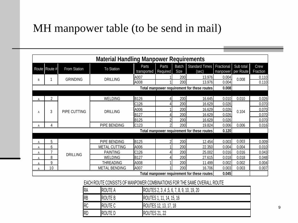
MH manpower table (to be send in mail)
Route Route # From Station To Station Parts transported
Parts Required
Batch Size
Standard Times (sec)
Fractional manpower
Sub total per Route
Crew Fraction
A007 1 200 13.976 0.004 0.110A008 1 200 13.976 0.004 0.110
0.008
A 2 WELDING B126 4 200 16.645 0.010 0.010 0.026C126 4 200 16.629 0.026 0.070A006 1 200 16.629 0.026 0.070B127 4 200 16.629 0.026 0.070B125 2 200 16.629 0.026 0.070
A 4 PIPE BENDING C123 2 200 19.824 0.006 0.006 0.0160.120
A 5 PIPE BENDING B125 2 200 12.454 0.003 0.003 0.009A 6 METAL CUTTING A006 1 200 22.350 0.004 0.004 0.010A 7 PAINTING C126 4 200 25.002 0.016 0.016 0.043A 8 WELDING B127 4 200 27.615 0.018 0.018 0.048A 9 THREADING A008 1 200 11.499 0.002 0.002 0.004A 10 METAL BENDING A007 1 200 16.706 0.003 0.003 0.007
0.045
1
3
0.008
0.104
GRINDING
PIPE CUTTING DRILLING
DRILLING
DRILLING
Material Handling Manpower Requirements
Total manpower requirement for these routes
Total manpower requirement for these routes
Total manpower requirement for these routes
B
A
EACH ROUTE CONSISTS OF MANPOWER COMBINATIONS FOR THE SAME OVERALL ROUTERA ROUTE A ROUTES 2, 3 ,4 ,5, 6, 7, 8, 9, 10, 19, 20RB ROUTE B ROUTES 1, 11, 14, 15, 16RC ROUTE C ROUTES 12, 13, 17, 18RD ROUTE D ROUTES 21, 22

10
Material Handling Requirement & Costs Table(Garcia/forms & checklists/ forms/S3MHT)

11
Material Handling Requirements & Costs Table Explained
n Equipment type – Type of equipment used from the layout planning charts
n Description – Details about the equipmentn Length – Length of the equipment, if applicable.n Capacity – The amount of weight the equipment can holdn No Req’d – The number of equipment pieces needed for
production, if applicablen Cost/Unit – The cost per unit of equipment or the cost per unit
of lengthn Total Cost – (No Req’d)*(Cost/Unit)n Annual Cost – (Total Cost – 10%*Total Cost)÷(Service Life)
12
Web resources for MH selection
n www.mhia.orgn www.yaleflorida.comn www.handlingconcepts.comn www.cisco-eagleonline.comn www.grossassociates.comn www.forktrucks.comn www.usroads.com/journals/rej/9704/re970404.htmn www.integratedstorage.comn www.raymondcorp.comn www.asapauto.comn www.king-way.comn www.fkilogistex.com

13
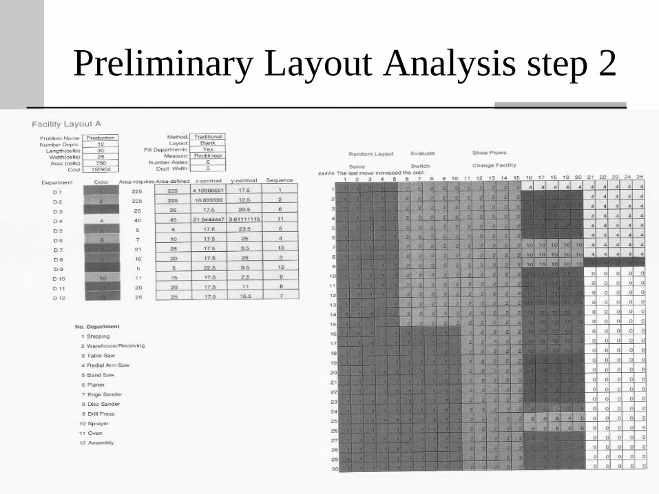
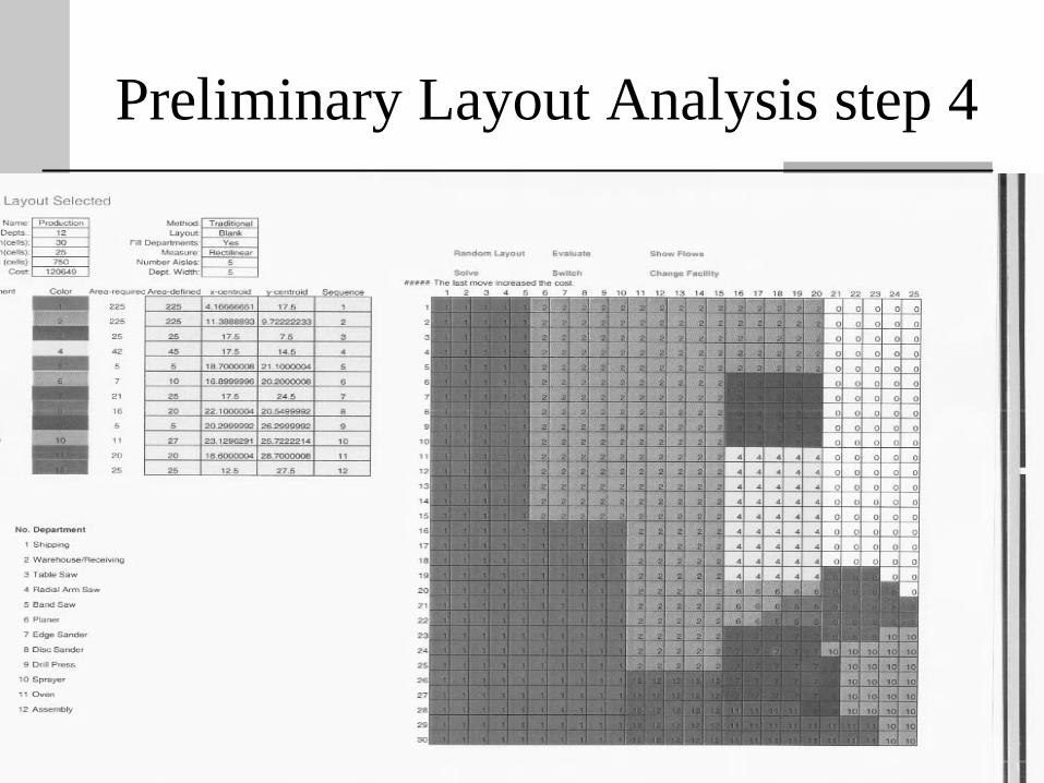
CRAFT-m
5. CRAFT-m outputs & block diagramso Use CRAFT to create proposed layouto Change constraints of fixed departments and
valuable relationships to transcribe the most desirable plant layout ( 2 solutions)

14
Preliminary Layout Analysis-step1
15
Preliminary Layout Analysis step 2

16
Preliminary Layout Analysis step 3
17
Preliminary Layout Analysis step 4

18
Proposed Layout drawing
n AutoCAD Drawing of Proposed Layouto From the proposed plant layout (CRAFT output),
use AutoCAD to create a block layout.o Label all stationso Dimension each departments and perimeter of the
proposed layouto Indicate the material flow lineso Include company name, Team Member who
completed the drawing, date, Scale, and the title of the drawing
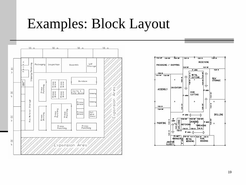
19
Examples: Block Layout
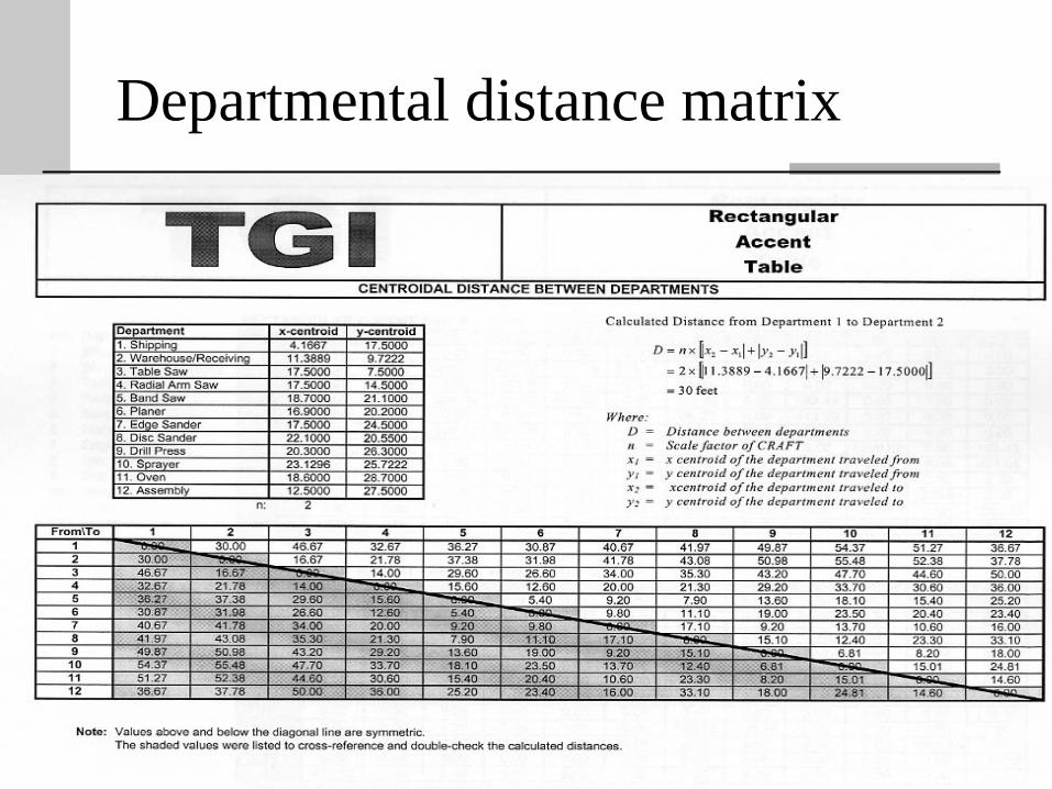
20
Departmental distance matrix

21
Layout Planning Charts (LPC)n A detailed description of the sequence of operations (largely
based on route sheets) for each part to aid layout planning process.
n Allows the planner to visualize combinations of operations, manpower, & machines.
n Notationo Fabrication - F - ?o Move - M - ?o Storage - S - ?o Inspection - I -n For each M the Layout Planning Chart documentso Frequency (# of moves per part)o Origin & destination of moveso Quantity being movedo Time per move

22
Format for Layout Plang. Chart (Garcia/forms & checklists/ forms/S3LPC or tamcam)

23
Layout Planning ChartsExplained
n St No. – Serial number of the step in the Layout Planning Chartn F M S I – Shade the type of operation that is occurring during the
current step n Description – Description of the operation including material handling
operationsn Time per piece – Standard time, from the route sheet (only for F type
of operation)n Machine or Equipment – Machine or equipment from the route sheet
(only for F type of operation)n Mach. Frac. – Fractional number of machines required, from the
machine requirements tablen Combine with- Use the machine fraction calculations table of Section II
and denote m/c codesn Mach Reqd – Machine Fraction rounded up, notice that the machines
can be shared with other operationsn Crew Frac –Summation of men fractions/ total men required

24
Layout Planning ChartsExplainedn Men Frac – Fractional number of men required, (Crew Frac) *
(number of operators required to operate the machine)n Men Reqd – Men required for the operation, i.e., rounded up
men frac, notice that the crew can be shared with other operations
n How Moved – How the material is moved from one operation to the next (only for M type of operations)
n Cont Type – Type of container used to move the material (only for M type of operation)
n Lot Size – Quantity moved per trip ( only for M type of operation)
n Dist. Moved – Distance traveled (only for M type of operation), you may need layout sketch to come out with these distances
n Remarks – Any comments about the operation

25
Appendix to Section V can Include..
n Photos, sketches of equipments, bins, racks, pallets selected
n Material Handling Annual Cost= (total cost-0.1X total cost)/ 10 yearsNote: Assumed 10% salvage value and 10 year service life
n Pounds Requiredn Pounds per dayn Cost per unitn Cost per yearn Material Requirements & Costs Excel Spreadsheet