reflections on the shape of a · pdf fileundershot / breast shot water wheel worked for four...
TRANSCRIPT

Reflections on the
Shape of a Turbomachine
Paul Gostelow

R-R Trent 1000 EngineWe are used to
seeing and analyzing
axial machines for
aero engines. Their
shapes may seem to
have converged but
exciting advances
are being made in
design techniques.
There is still strong
progress to be made
for economy and
environment from
these improvements.
Today I would like to
take a wider look at
opportunities in
newer applications
where designs have
not yet converged.

Hero‟s Turbine
This 2000 year old
turbine is from Hero of
Alexandria.
The young engineer,
when confronted with
an unusual
turbomachine like this,
should be able to
classify it and
understand how it
operates. Should be
able to repair it and
maybe re-design it to
work better.

I will firstly present a taxonomy of turbomachines.
This should permit turbines of widely varying
geometry and layout to be identified and
classified. The process is illustrated with
reference to different configurations of hydraulic
and free flow turbines.
turbo – turbinis (L) ___ I spin

Taxonomy
Some Examples
Design Methodology
Low Pressure Turbines
Streamwise Vorticity
Blade Sweep

So how do we classify turbomachines?
Taxonomy of Turbomachinery
Does it look cluttered? It is, because we are dealing with a very wide range of
machines. Although they operate according to the same fundamental laws the
variety of purposes, constraints and geometries is enormous.
To reduce some of the confusion I will remove the work-absorbing machines, such
as compressors and pumps, because today we are mainly discussing turbines.
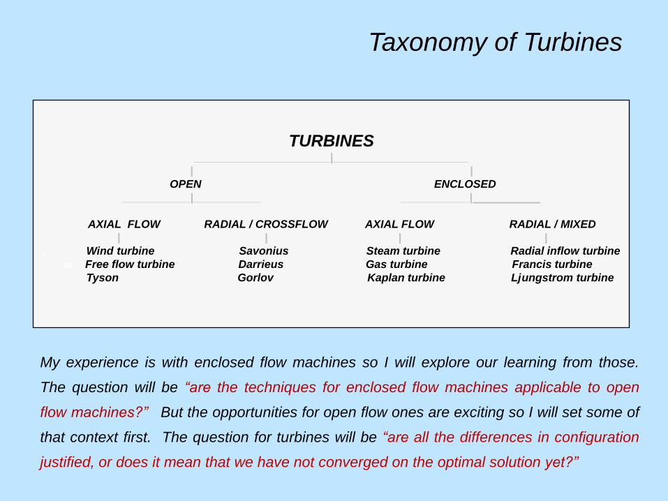
TURBINES______________________|______________________
| |
OPEN ENCLOSED
___________|___________ ___________|___________
AXIAL FLOW RADIAL / CROSSFLOW AXIAL FLOW RADIAL / MIXED
| | | |
. Wind turbine Savonius Steam turbine Radial inflow turbine
w Free flow turbine Darrieus Gas turbine Francis turbine
Tyson Gorlov Kaplan turbine Ljungstrom turbine
Taxonomy of Turbines
My experience is with enclosed flow machines so I will explore our learning from those.
The question will be “are the techniques for enclosed flow machines applicable to open
flow machines?” But the opportunities for open flow ones are exciting so I will set some of
that context first. The question for turbines will be “are all the differences in configuration
justified, or does it mean that we have not converged on the optimal solution yet?”

Taxonomy
Some Examples
Design Methodology
Low Pressure Turbines
Streamwise Vorticity
Blade Sweep

An example from Hawaii
Ingenious Streetlamp
Use of a Savonius Rotor
OPEN
CROSSFLOW

An example of open crossflow from
Suffolk that is over 800 years old
Woodbridge Tidal Mill
Use of tidal
power is not
new.
A tidal mill has
operated on this
site since 1170 AD
- others since
the Romans.
Undershot / breast
shot water wheel
worked for four
hours each day,
at ebb tide.
OPEN
c CROSSFLOW

Conventional
Overshot Water WheelsSaugus Iron Works near Boston MA
OPEN
CROSSFLOW
Water wheel
technology.
Enthusastically
adopted in the
new world.

Some Free Flow or
„Run of the River‟
Turbines
OPEN
CROSSFLOW
Norias on the Orontes
River in Hama, Syria.
Some date from C4th BC.
Combined undershot
water wheel and pump.

River Rance, 240 MWBrittany, France
The biggest
operating
tidal scheme.
Opened in
1966.
ENCLOSED
AXIAL
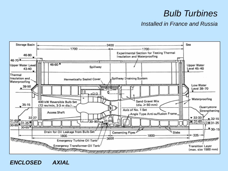
Bulb TurbinesInstalled in France and Russia
ENCLOSED AXIAL

Annapolis Royal, 20 MWBay of Fundy, Nova Scotia, Canada
Generating
station
opened in
1984.
DUCTED /
ENCLOSED
AXIAL

Installed on seabed in
Bay of Fundy, Nova Scotia.
Bi-directional flow.
Canada has the biggest
tides in the world; it should
succeed with tidal power.
It is also well placed to
exploit run of the river
turbines.
DUCTED / OPEN
AXIAL
OpenHydro 1 MW Tidal Turbine

Oxford TurbineSpecifically
designed for
hydro-electric
applications in
free flowing low
head and tidal
waters.
Strength comes
from triangulated
structure.
OPEN
CROSSFLOW /
TRIANGULATED

Clean Current Tidal TurbineClean Current‟s tidal turbine
generator is a bi-directional
ducted horizontal axis turbine
with a direct drive variable
speed permanent magnet
generator. Over 50% overall
efficiency claimed, Simple
design that has one moving
part - the rotor assembly
containing the permanent
magnets. No drive shaft or
gearbox. Demonstration project
at Race Rocks, BC. 1/4 scale,
65 KW turbine, installed 2006,
powers lighthouse, weather
station and infrastructure.
ENCLOSED (DUCTED)
AXIAL

Lunar Energy
UK-based tidal energy
device developer. Bi-
directional cone structure
with turbine and power
conversion components in a
removable central cassette.
The human figure gives a
good sense of the size of
tidal turbines. Lunar
completed proof of concept
testing in the laboratory and
is currently building a full
scale 1 MW device for
installation on Orkney.
ENCLOSED AXIAL

EnCurrent Turbine
Mounted for testing at NRC
Institute for Ocean Technology
OPEN
CROSSFLOW
Builds on VAHT
work performed by
NRC. Lift generated
as water passes
over vertical
hydrofoils. Based
on Darrieus design,
turbine captures
40% to 45% of
energy in moving
water. Suitable for
flow velocity of 1.5
to 3.5 m/s.

Operates in both ebb
and flood tides.
1/40th scale model
tested by Newcastle
University.
1/10th scale model
deployed in
Strangford Loch,
N. Ireland.
OPEN AXIAL
Evopod Tidal Turbine

Marine Current
Turbines
OPEN
AXIAL
.

The Wells Turbine
Specifically
designed to
capture the
oscillating flows
of wave energy.
Note the zero
stagger blading.
CLOSED
AXIAL
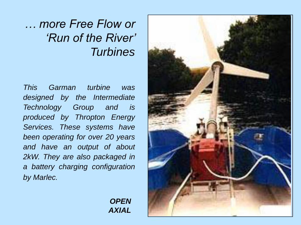
… more Free Flow or
„Run of the River‟
Turbines
This Garman turbine was
designed by the Intermediate
Technology Group and is
produced by Thropton Energy
Services. These systems have
been operating for over 20 years
and have an output of about
2kW. They are also packaged in
a battery charging configuration
by Marlec.
OPEN
AXIAL

The Tyson Turbine - from Wagga Wagga, Australia
Mounted on a floating pontoon platform and usually moored in mid-stream of
a flowing river. Both rotating and reciprocating outputs are available from the
gearbox. Reciprocating operates a positive displacement pump for water;
Rotating drives rotating machinery to provide DC power to charge batteries
directly at the riverside or AC for longer distance transmission up to 5 km.
My friend and colleague Alex Revel did good work on this and other turbines.
He had a great instinctive feel for the best shape of turbomachine for the job
in hand. He died last year and I would like to dedicate this talk to his memory.
OPEN AXIAL
Flow

Gorlov Helical TurbineDesigned for hydro-electric
applications in free-flowing low
head water. Turbine rotates in
same direction, independent of
flow direction and can be
assembled vertically,
horizontally or in any other
crossflow combination.
Common shaft and generator
used for an array of multiple
turbines. The overlap of the
blades twisted around the
circumference ensures some
of the blade is always at an
optimum angle relative to the
flow to generate lift. This
enables the turbine to spin with
minimal cavitation or vibration.
OPEN
CROSSFLOW / HELICAL

Quiet Revolution
Helical Turbine
This was atop the Kettleby
Cross pub., Melton Mowbray.
OPEN
CROSSFLOW / HELICAL

What Shape?
With this great variety of shapes and sizes how does the designer go about
selecting the most appropriate for the application? From dimensional
analysis the concept of specific speed is useful. This works for pumps or
turbines, air or water, and is particularly effective for cavitation avoidance.
The specific speed of a pump is given by: Ns = N(Q1/2H-3/4)
For a turbine the equivalent is: Ns = N(P1/2H-5/4)N is rot. speed, Q is flow, H is head, P is power, p is pressure, v is velocity.
In this way the optimum shape of a turbine can be realised, based on the
power output, P, and the head, H. Ranges of Ns are: Pelton 10 – 30,
Crossflow 20 – 200, Francis 30 – 400, Propeller and Kaplan 200 – 1000.
Dimensional analysis also gives us the cavitation number; this is a reliable
indicator for cavitation avoidance: s = (pat – pv + H)/ (½ r v2)

What Specific Speed do the power and head indicate?
Low Ns, - Pelton Wheel, or high Ns, - Axial Flow Turbine?

Enclosed Axial FlowOnce the general shape of
the turbine is established
the designer looks for the
mathematical design tools
to do the job.
The most complete aero
design tools have been
developed for the enclosed
turbines of aircraft engines.
These turbines can give
93% efficiency and provide
a benchmark.
The author‟s background is
in research and design on
enclosed flow turbines for
aircraft propulsion. The
design framework is
introduced and could be
useful for hydro turbine
design.

Taxonomy
Some Examples
Design Methodology
Low Pressure Turbines
Streamwise Vorticity
Blade Sweep

S1 and S2 SurfacesChung-Hua Wu, 1949
The first systematic
approach was introduced
by Prof. Chung Hua Wu
sixty years ago. The
turbine is divided into S2
(meridional) and S1
(cascade) planes and
the flow is solved on
each of these, iteratively
relaxing between them.

The Meridional Plane (r,z)
The meridional plane
forms the basic
design and
organisational unit.
The flow is solved for
these streamlines.
(Consider here
whether we are
dealing with swept
blades.)

The Radial Equilibrium
Equation of Turbomachinery
L. H. Smith Jr., 1954
The radial equilibrium equation was established
and solved by Dr. L. H. Smith Jr. at GE in 1954.
That original FORTRAN program, now known as
CAFMIX, is still in use for preliminary design at GE.
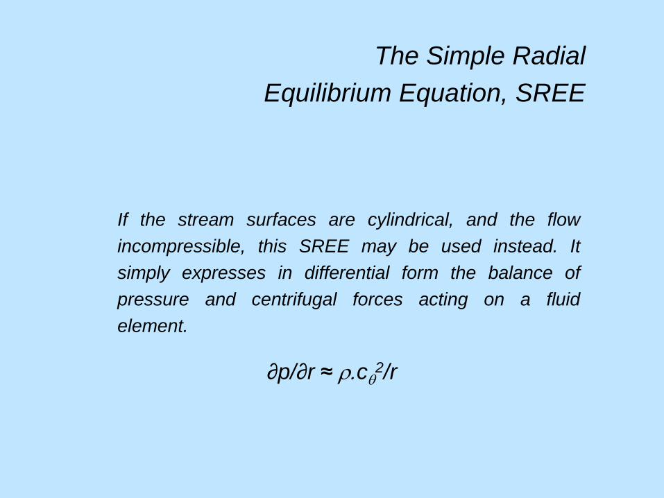
If the stream surfaces are cylindrical, and the flow
incompressible, this SREE may be used instead. It
simply expresses in differential form the balance of
pressure and centrifugal forces acting on a fluid
element.
The Simple Radial
Equilibrium Equation, SREE
∂p/∂r ≈ r.cq2/r

The Cascade Plane (q,z)
Once the radial
equilibrium equation
is solved the overall
shape is established.
It is then necessary to
consider the cascade
plane in which the
essential turning and
losses are addressed.
This is where the
blade is shaped and
where the efficiency
is determined.

University of Leicester
Transonic Blowdown
Turbine Nozzle
Cascade Tunnel
The cascade plane is all about
the flow physics. The most
usual approach is to unroll the
blades onto a linear cascade
and to measure the turning and
losses in a wind tunnel.

Spark schlieren photograph by
Aldo Rona and computational
schlieren prediction.
At the design condition we
routinely get good agreement
between experiment and CFD.
Off-design and with aggressive
3D shaping, such as blade
sweep, is a different story.
Mach 1.2
discharge from
turbine blade
Experiment RANS Computation

NRC Continuous Inflow
Planar Cascade Tunnelfor Transonic Turbine Blading

NRC Turbine Nozzle
Experiments and
Inviscid CFD
Isentropic Mach Number
Distribution Mach 0.8 and 1.16
The use of advanced RANS and LES
computational procedures is routine
but end wall and off design effects are
still not well-predicted, even for
enclosed flow turbomachinery. This
often results in serious efficiency
penalties, directly impacting on fuel
costs and with adverse
environmental consequences.

Flow Visualization
on a Compressor Blade
Although nominally 2D the flows can be quite 3D.
T.E. L.E. L.E. T.E.

Visualization of
Secondary Flows
Near the End
Wall in a Turbine
CascadeCourtesy, J. Fabri
∂p/∂n ≈ r.cq2/R

Taxonomy
Some Examples
Design Methodology
Low Pressure Turbines
Streamwise Vorticity
Blade Sweep

Low Pressure Turbines
- and weight reduction
The Low Pressure Turbine (LPT) can contribute as much
as 30% of the weight of an aircraft engine and contain
as many as 1900 blades. This is the obesity problem
that modern aero-engines share.
Weight reduction programs involving high-lift LPTs have
been implemented for engines such as the Rolls-Royce
BR715 for the Boeing 717 and the P&W/GE GP7000 for
the Airbus A380. Current engines using high-lift turbine
blading include the Rolls-Royce Trent 1000 and General
Electric GEnx for the Boeing 787 Dreamliner.

Low Pressure Turbines
and Weight Reduction – GE‟s GEnx
New Revolutionary Turbine!
The job of the high and low
pressure turbines is to extract
work from core flow. This
efficiency has never been better,
thanks to recent improvements in
design codes and turbine blade
architecture. Fewer blades can
now do the job more efficiently,
while simultaneously reducing
cost and weight. (GE brochure)
“In an effort to get a lightweight
design, we took too many airfoils
out of the turbine, and the engine
told us it didn’t like that.”
(T. Brisken, GE project manager)

Reynolds Number Effects- on turbine blade losses
Altitude
cruise
Take-off
LPT efficiency falls off between
sea level take-off and altitude
cruise conditions due to a halving of
Reynolds number. This can result in a 40% increase in losses.

Low Pressure Turbines
- the issues
Workshops were convened twenty years ago to address the weight
reduction issue; highly-loaded low pressure turbine blading was conceived in
the process. Extensive collaboration between universities and industry in
attempts to understand boundary layer behavior on turbine airfoil surfaces
dominated by unsteady transitional flows. These turbines were eventually
deployed in commercial aircraft and major savings in engine weight and cost
were achieved, but with a significant penalty in turbine efficiency. It is thought
that design procedures have not adequately addressed issues such as
secondary flows, purge flows and tip clearances, known to be principal
contributors to loss. RANS codes are not performing well for transitional,
separated and three dimensional flows. Research is now aimed at regaining
the lost efficiency whilst retaining the hard-won weight and cost advantages.

Low Pressure Turbines
- impact of efficiency improvements
The LPT has a larger impact on the fuel consumption of
commercial aircraft engines than other components. If the LPT
efficiency is improved by 1%, then the fuel consumption for the
engine is reduced by 0.7 to 0.95%. It is important to improve the
performance of all components but incentives for the LPT are
particularly high. To reduce CO2 signature, emissions and noise
the best return on investment will be gained by improving the LPT
efficiency. Raising this from 93% to 95% would yield a 1.8% fuel
consumption reduction for aircraft engines.

Taxonomy
Some Examples
Design Methodology
Low Pressure Turbines
Streamwise Vorticity
Blade Sweep

The Challenge of Vorticity
The difficulties presented by secondary flow vortices and
three dimensional flows are discussed. A recent discovery is
that of organized fine-scale streamwise vortical structures on
turbine blading. This has aerodynamic and heat transfer
implications and raises questions of leading edge bluntness,
surface curvature and blade sweep.

Streamwise Vortices
The stability of contra-rotating vortex pairs is of
airworthiness and commercial interest but is not well understood

Contra-rotating
Streamwise Vortices
Previous investigators observed streamwise vortices and
“streaky structures” on flat plates and on the suction surface of
compressor blades. An organized system of contra-rotating
streamwise vortex pairs on a circular cylinder, or a compressor
or turbine blade suction surface, gives additional complications.
Experiments conducted on flow past transonic turbine
blades and a circular cylinder in subsonic crossflow. Organized
streamwise vortex systems were observed for both cases. This
unfamiliar behavior, and the associated spanwise wavelength,
had been predicted and observed in low speed flows. Turbine
designers generally assume that streamwise vorticity is
confined to the concave pressure surfaces. Examples will be
given that should result in questioning this assumption.

Conditions at Leading
Edge of Turbine Blade
The L.E. inflow
is initially
disturbed; then
undergoes
rapid curvature
changes before
joining the
convex suction
surface. Vortex
stretching is
caused by both
turbulence and
curvature.
Contributions of
Stability Theory
For a convex surface streamwise vorticity is consistent
with the later predictions of Görtler (1955), who
postulated instability on a convex surface from the
concave streamlines ahead of the L.E. stagnation region.
A useful approach for a circular cylinder is that of
Kestin and Wood (1970). Their stability analysis for
approaching flow considered regularly distributed contra-
rotating eddies strengthened by eddy-stretching in free
stream turbulence. They predicted a spanwise
wavelength between pairs, l, for a cylinder of diameter,
D, given by:
l = 1.79π D Re-0.5.

Suction surface flow visualization
NRC Turbine Blade; Me = 1.16
Under the
influence of
strong
favorable
pressure
gradients on
the blade‟s
suction surface
streamwise
vortices were
observed that
persisted to the
trailing edge.

NRC Turbine Blade
The suction surface leading edge is virtually circular; it then
develops strong convex curvature becoming quite flat further
downstream.
Suction surface flow visualization was performed at three
speeds, displaying coherent streamwise vorticity extending to the
trailing edge. The blade was covered with a sheet of self adhesive
white vinyl; a mixture of linseed oil and powdered lampblack was
applied in a very thin layer. After running for five minutes, the blade
was removed and photographed.
Large numbers on the scale represent percentage axial chord
and small numbers mark static tap locations. For Me = 1.16 the
shock impingement and separation region is at an axial chord
around 70%.

Streamwise Vorticity
The streamwise vorticity can be caused by vortex stretching,
streamline curvature or turbulence. Kestin and Wood predicted and
measured streamwise vorticity on the forward quadrant of a cylinder.
Can we expect similar fine scale streamwise vorticity on convex
surfaces such as turbine blades? To what extent would they affect the
flow and heat transfer and how should we go about modeling it?
Published examples of visualization from compressor and turbine
blade suction surfaces were examined to see if a consistent
wavelength existed between streaks. In all cases repeatability of
measurements from photographs was high.

Streamwise Vortices
on Turbine Blade
Suction SurfaceBenner
Turb. Level 0.3%

Evaluation of Turbine
and Compressor Blading
The turbine blade leading edge is blunt but has high curvature;
subsequently the suction surface initially retains strong convex
curvature but is flat further downstream; what effective
diameter should be used for comparing with theory?
According to the theory the measured wavelength, of 0.55mm,
is compatible with the surface curvature on the suction surface
at around 10% true chord. The diameter of the osculating circle
on the suction surface, at 10% true chord, was therefore taken
as the value of D.

Wavelength Measurements and comparison with Kestin and Wood predictions
.■
■
●
●
● Compressor blade – Schulz & Gallus
.■ Compressor blade – Weber et al.
● Turbine cascade – Mahallati
.■ Turbine cascade – Benner et al.
▼ Turbine cascade – Hodson & Dominy
▲ Turbine cascade – Halstead
.▼
▲
▲
▲

Compressor Bladepressure surface
McMullan LES
on Monterey
compressor blade
Low angle of attack
Flow behavior at
leading edge;
streamwise vorticity
and separation on
pressure surface.

Close up of Leading Edge
pressure surface
The toroidal vortex structures appear
to produce streamwise vortices.
But where did they originate,
suction surface or upstream?

Taxonomy
Some Examples
Design Methodology
Low Pressure Turbines
Streamwise Vorticity
Blade Sweep

Sweep and
Dihedral of
Lifting
SurfacesR.I. Lewis,
J. Mech. Eng. Sci., 1971
Blade sweep is also
very relevant for
free flow turbines

Quiet Revolutionhelical VAWT design
OPEN
CROSSFLOW / HELICAL

Swept back
transonic fan rotor:
45 years ago!
The theory for blade sweep
and dihedral was developed
by Smith and Yeh and
published in 1963 in Trans.
ASME, J. Basic Eng.

Swept and Canted Blades

Rolls-Royce Turbine Blades
Shrouded blades
and honeycomb
Notice use of
sweep – which
are swept, the
rotor blades or the
stator blades?
Which are
canted?

Poll and Kestin Results
Does crossflow instability cut in at about 38o?
What is missing is reliable experimental data with
sweep between zero and 55o.
0.0
0.5
1.0
1.5
2.0
2.5
0 10 20 30 40 50 60 70 80
Sweep (deg.)
339000
385000
432000
485000
528000
100λ/D
Streamline curvature
instability (Kestin)
Crossflow instability (Poll)
Reynolds No.
Circular Cylinder in Cross Flow

Streamwise and Crossflow
Velocity Profiles
The cross flow profile
develops an obvious and
aggressive instability as
the sweep increases,
resulting in severe cross
flow vorticity. The next
slide, of the flow over a
fuselage (effectively a
circular cylinder with 60o
sweep) shows this quite
clearly.

Streaks on Fuselage Indicate
Crossflow VorticesSurface Visualization by Hanff

Curvilinear Nozzle Blades
and associated loss improvement
Filippov and Wang, 1964

Effect of Inclination on Losses
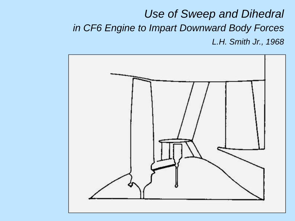
Use of Sweep and Dihedral
in CF6 Engine to Impart Downward Body Forces
L.H. Smith Jr., 1968

Conclusions - 1
• A taxonomy of turbomachines is presented, permitting turbines of widely varying
geometry and layout to be identified and classified. The process is illustrated with
reference to different configurations of hydraulic and free flow turbines.
• The framework employed for analysis and design of enclosed axial turbomachines
is introduced. Although the traditional approach to the design of enclosed turbines
uses intersecting two dimensional planes it is recognized that all turbomachinery
flows are three dimensional and unsteady. The use of advanced RANS and LES
computational procedures is routine but these effects are still not well-predicted.
• Universities and industry have collaborated in the last two decades to produce
highly-loaded low pressure turbines. Deployed in commercial aircraft and major
savings in engine weight and cost achieved, but with a penalty in turbine efficiency.
Research now aimed at regaining lost efficiency but retaining weight and cost gains.

Conclusions - 2
• Streamwise streaks are present in the laminar portion of the flow over the
convex surfaces of circular cylinders and turbomachinery blades. Consistent
spanwise wavelengths indicate organized behavior. Confirmation needed.
• Measured spanwise wavelengths of the periodic vortex arrays on blading are
predicted quite well by the Kestin and Wood theory. If this behavior is common it
will have implications for blade aerodynamic and cooling design.
• The sweep question seems particularly relevant for most approaches to the
design of free flow turbines. This is an important part of the analysis for most
blades.

Conclusions - 3
• The shape of a turbomachine is vitally important. It responds to and affects its
environment and its operation in that environment. It should never become the
object of a graphic designer’s whim.
• The fact that open flow machines have so many different shapes and
configurations tells us that they are responding to a very wide range of
environments and functions but also that their design technology is far from
mature. And that is why good turbomachinery designers have a job that is always
interesting and varied – a job for life.
• For progress to be maintained it is essential for analytical, computational and
experimental work to proceed in a balanced, collaborative and interactive manner.
Best achieved by the relaxation of traditional disciplinary barriers in universities
and industry.