refrigerant 717 ammonia products - refrigeration · pdf filerefrigerant 717 ammonia products...
TRANSCRIPT
� Thermostatic Expansion Valves
� Refrigerant Distributors
� Solenoid Valves
� Replaceable Core Filter Dryers
� Strainers
� Level Master Controls
� Sight Glasses
Refrigerant 717 Ammonia Products
Catalog R/S 717Transitional Reference Guide from Sporlan to R/S Valves
R S/
Thermostatic Expansion Valves . . . . . . . . . . . . . . . . . . . . . . . . . . . 3
Refrigerant Distributors . . . . . . . . . . . . . . . . . . . . . . . . . . . . . . . . . 8
Solenoid Valves . . . . . . . . . . . . . . . . . . . . . . . . . . . . . . . . . . . . . . .11
Parker Replaceable Core Filter Dryers . . . . . . . . . . . . . . . . . . . . .15
Strainers . . . . . . . . . . . . . . . . . . . . . . . . . . . . . . . . . . . . . . . . . . . .16
Level Master Liquid Level Control . . . . . . . . . . . . . . . . . . . . . . . . .17
Sight Glasses . . . . . . . . . . . . . . . . . . . . . . . . . . . . . . . . . . . . . . . . 20
Parker Hannifin CorporationRefrigerating Specialties (R/S) Broadview, IL 60155
Table of Contents
2
Note: Since Parker’s acquisition of Sporlan Valve Company in 2004, All Sporlanbrand ammonia products are now marketed under the Parker R/S name.
Parker Hannifin CorporationRefrigerating Specialties (R/S) Broadview, IL 60155
Catalog R/S 717
3
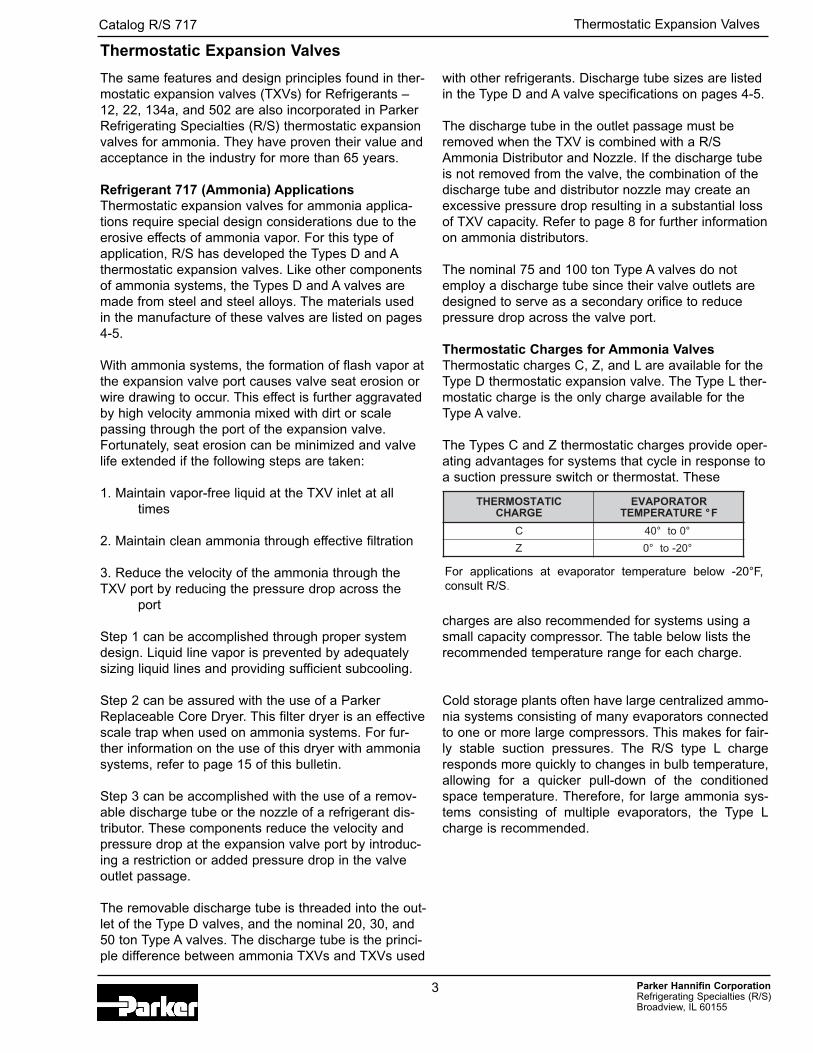
The same features and design principles found in ther-mostatic expansion valves (TXVs) for Refrigerants –12, 22, 134a, and 502 are also incorporated in ParkerRefrigerating Specialties (R/S) thermostatic expansionvalves for ammonia. They have proven their value andacceptance in the industry for more than 65 years.
Refrigerant 717 (Ammonia) ApplicationsThermostatic expansion valves for ammonia applica-tions require special design considerations due to theerosive effects of ammonia vapor. For this type ofapplication, R/S has developed the Types D and Athermostatic expansion valves. Like other componentsof ammonia systems, the Types D and A valves aremade from steel and steel alloys. The materials usedin the manufacture of these valves are listed on pages4-5.
With ammonia systems, the formation of flash vapor atthe expansion valve port causes valve seat erosion orwire drawing to occur. This effect is further aggravatedby high velocity ammonia mixed with dirt or scalepassing through the port of the expansion valve.Fortunately, seat erosion can be minimized and valvelife extended if the following steps are taken:
1. Maintain vapor-free liquid at the TXV inlet at alltimes
2. Maintain clean ammonia through effective filtration
3. Reduce the velocity of the ammonia through theTXV port by reducing the pressure drop across the
port
Step 1 can be accomplished through proper systemdesign. Liquid line vapor is prevented by adequatelysizing liquid lines and providing sufficient subcooling.
Step 2 can be assured with the use of a ParkerReplaceable Core Dryer. This filter dryer is an effectivescale trap when used on ammonia systems. For fur-ther information on the use of this dryer with ammoniasystems, refer to page 15 of this bulletin.
Step 3 can be accomplished with the use of a remov-able discharge tube or the nozzle of a refrigerant dis-tributor. These components reduce the velocity andpressure drop at the expansion valve port by introduc-ing a restriction or added pressure drop in the valveoutlet passage.
The removable discharge tube is threaded into the out-let of the Type D valves, and the nominal 20, 30, and50 ton Type A valves. The discharge tube is the princi-ple difference between ammonia TXVs and TXVs used
with other refrigerants. Discharge tube sizes are listedin the Type D and A valve specifications on pages 4-5.
The discharge tube in the outlet passage must beremoved when the TXV is combined with a R/SAmmonia Distributor and Nozzle. If the discharge tubeis not removed from the valve, the combination of thedischarge tube and distributor nozzle may create anexcessive pressure drop resulting in a substantial lossof TXV capacity. Refer to page 8 for further informationon ammonia distributors.
The nominal 75 and 100 ton Type A valves do notemploy a discharge tube since their valve outlets aredesigned to serve as a secondary orifice to reducepressure drop across the valve port.
Thermostatic Charges for Ammonia ValvesThermostatic charges C, Z, and L are available for theType D thermostatic expansion valve. The Type L ther-mostatic charge is the only charge available for theType A valve.
The Types C and Z thermostatic charges provide oper-ating advantages for systems that cycle in response toa suction pressure switch or thermostat. These
charges are also recommended for systems using asmall capacity compressor. The table below lists therecommended temperature range for each charge.
Cold storage plants often have large centralized ammo-nia systems consisting of many evaporators connectedto one or more large compressors. This makes for fair-ly stable suction pressures. The R/S type L chargeresponds more quickly to changes in bulb temperature,allowing for a quicker pull-down of the conditionedspace temperature. Therefore, for large ammonia sys-tems consisting of multiple evaporators, the Type Lcharge is recommended.
Thermostatic Expansion Valves
CITATSOMREHTEGRAHC
ROTAROPAVEERUTAREPMET F°
C °0ot°04
Z °02-ot°0
For applications at evaporator temperature below -20°F,consult R/S.
Thermostatic Expansion Valves
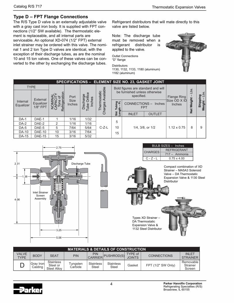
The R/S Type D valve is an externally adjustable valvewith a gray cast iron body. It is supplied with FPT con-nections (1/2” SW available). The thermostatic ele-ment is replaceable, and all internal parts areserviceable. An optional XD-074 (1/2” FPT) externalinlet strainer may be ordered with this valve. The nomi-nal 1 and 2 ton Type D valves are identical, with theexception of their discharge tubes, as are the nominal10 and 15 ton valves. One of these valves can be con-verted to the other by exchanging the discharge tubes.
Refrigerant distributors that will mate directly to thisvalve are listed below.
Note: The discharge tubemust be removed when arefrigerant distributor isapplied to the valve.
Outlet Connections“D” flange
Distributors1130, 1132, 1133, 1180 (aluminum)1182 (aluminum)
Parker Hannifin CorporationRefrigerating Specialties (R/S) Broadview, IL 60155
Catalog R/S 717
TNIOJTEKSAG,32.ONEZISTNEMELE–SNOITACIFICEPSEPYT
troPeziS
sehcnI
dloB lliwdnadradnatseraserugifesiwrehtosselnudehsinrufeb
.deificeps gniRegnalFDIXDOeziS
sehcnIlanretnIrezilauqE
lanretxErezilauqE
TPF"8/1–SNOITCENNOC sehcnI
TPF
TELNI TELTUO
1-AD 1-EAD 1 61/1 23/1
L-Z-C
5
01
51
2/1ro,8/3,4/1 57.0x21.1 8 92-AD 2-EAD 2 61/1 61/15-AD 5-EAD 5 46/7 46/5
01-AD 01-EAD 01 61/3 46/751-AD 51-EAD 51 61/3 23/5
sehcnI–SEZISBLUB
SEGRAHCTNAREGIRFERainommA–717
L-Z-C 00.4x57.0
NOITCURTSNOCFOSLIATED&SLAIRETAMEVLAV
EPYT YDOB TAES NIP NIPREIRRAC )S(DORHSUP foEPYT
STNIOJ SNOITCENNOC TELNIRENIARTS
D norIyarGgnitsaC
sselniatSroleetSyollAleetS
netsgnuTedibraC
sselniatSleetS
sselniatSleetS teksaG )ylnOWS"2/1(TPF
elbavomeRreniartS
neercS
NO
MIN
AL
CA
PA
CIT
YTo
ns o
f R
efrig
erat
ion
Dis
char
geT
ube
Orif
ice
Inch
es
The
rmos
tatic
C
harg
es A
vaila
ble
Std
. Tu
bin
gL
eng
th –
Ft.
Net
Wei
gh
t–
Lbs.
Sh
ipp
ing
Wei
gh
t–
Lbs.
Compact combination of XDStrainer – MA5A3 SolenoidValve – DA ThermostaticExpansion Valve & 1130 SteelDistributor
Types XD Strainer –DA ThermostaticExpansion Valve & 1132 Steel Distributor
2.75
2.31
4.06
1.38
3.25
5.06
Inlet StrainerScreen
Assembly
Type D – FPT Flange Connections
Discharge Tube
4
Thermostatic Expansion Valves
Parker Hannifin CorporationRefrigerating Specialties (R/S) Broadview, IL 60155
Catalog R/S 717
5
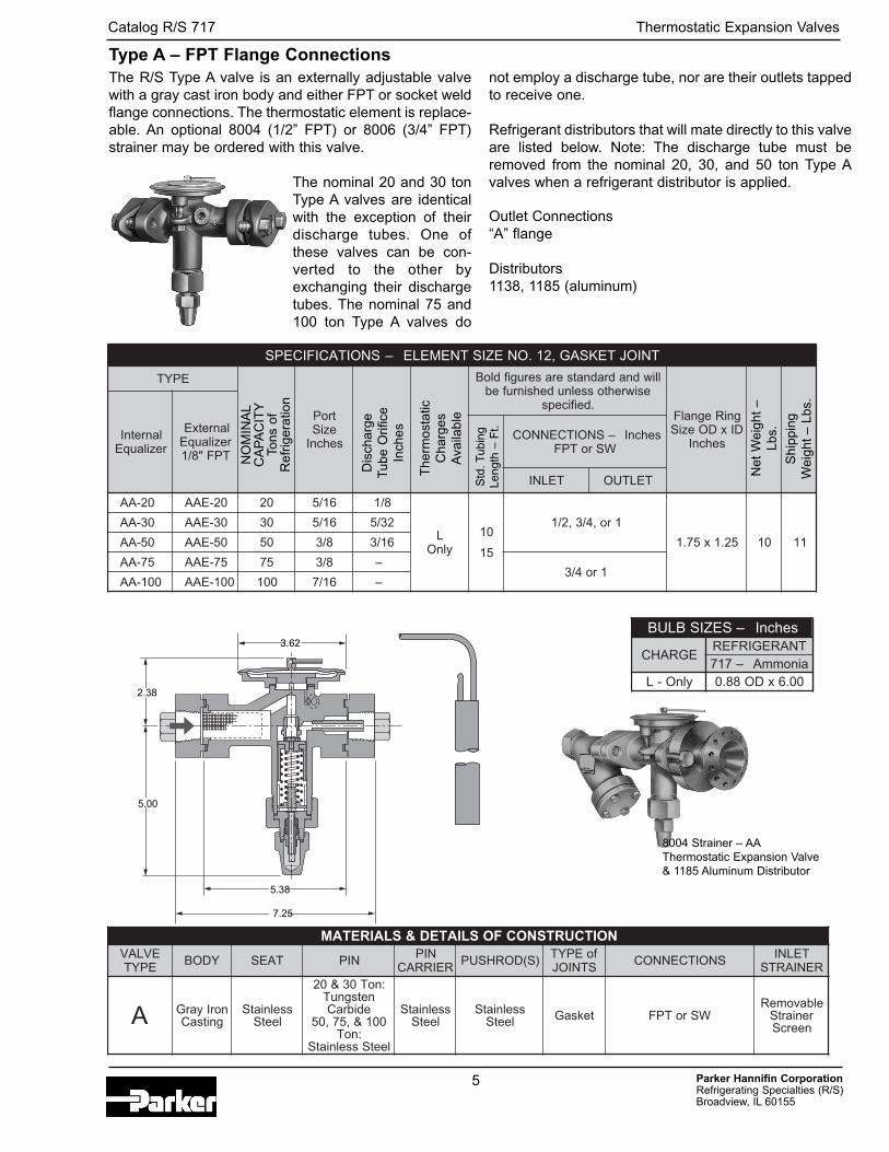
The R/S Type A valve is an externally adjustable valvewith a gray cast iron body and either FPT or socket weldflange connections. The thermostatic element is replace-able. An optional 8004 (1/2” FPT) or 8006 (3/4” FPT)strainer may be ordered with this valve.
The nominal 20 and 30 tonType A valves are identicalwith the exception of theirdischarge tubes. One ofthese valves can be con-verted to the other byexchanging their dischargetubes. The nominal 75 and100 ton Type A valves do
not employ a discharge tube, nor are their outlets tappedto receive one.
Refrigerant distributors that will mate directly to this valveare listed below. Note: The discharge tube must beremoved from the nominal 20, 30, and 50 ton Type Avalves when a refrigerant distributor is applied.
Outlet Connections“A” flange
Distributors1138, 1185 (aluminum)
Type A – FPT Flange Connections
NOITCURTSNOCFOSLIATED&SLAIRETAMEVLAV
EPYT YDOB TAES NIP NIPREIRRAC )S(DORHSUP foEPYT
STNIOJ SNOITCENNOC TELNIRENIARTS
A norIyarGgnitsaC
sselniatSleetS
:noT03&02netsgnuT
edibraC001&,57,05
:noTleetSsselniatS
sselniatSleetS
sselniatSleetS teksaG WSroTPF
elbavomeRreniartS
neercS
8004 Strainer – AAThermostatic Expansion Valve& 1185 Aluminum Distributor
3.62
Thermostatic Expansion Valves
SNOITACIFICEPS TNIOJTEKSAG,21.ONEZISTNEMELE–
EPYT
troPeziS
sehcnI
lliwdnadradnatseraserugifdloBesiwrehtosselnudehsinrufeb
.deificepsgniRegnalFDIxDOeziS
sehcnII lanretn
rezilauqE
lanretxErezilauqE
TPF"8/1
sehcnI–SNOITCENNOCWSroTPF
TELNI TELTUO
02-AA 02-EAA 02 61/5 8/1
LylnO
01
51
2/1 , 1ro,4/3
52.1x57.1 01 11
03-AA 03-EAA 03 61/5 23/5
05-AA 05-EAA 05 8/3 61/3
57-AA 57-EAA 57 8/3 –4/3 1ro
001-AA 001-EAA 001 61/7 –
NO
MIN
AL
CA
PA
CIT
YTo
ns o
fR
efrig
erat
ion
Dis
char
geT
ube
Orif
ice
Inch
es
The
rmos
tatic
C
harg
esA
vaila
ble
Std
. T
ubin
gLe
ngth
– F
t.
Net
Wei
ght
–Lb
s.
Shi
ppin
gW
eigh
t –
Lbs.
sehcnI–SEZISBLUB
EGRAHCTNAREGIRFERainommA–717
ylnO-L 00.6xDO88.02.38
5.00
5.38
7.25
SEGRAHCCITATSOMREHTLAdnaZA
EVLAVEPYT
LANIMONYTICAPAC
TROPEZIS
EGRAHCSIDEZISEBUT
ERUTAREPMETROTAROPAVE F°°01- °02-
isp–EVLAVSSORCAPORDERUSSERP021 041 061 081 021 041 061 081
D 1 61/1 23/1 16.0 66.0 17.0 57.0 25.0 65.0 06.0 36.0
D 2 61/1 61/1 60.1 41.1 22.1 92.1 98.0 69.0 30.1 90.1
D 5 46/7 46/5 84.2 86.2 78.2 40.3 90.2 62.2 24.2 65.2
D 01 61/3 46/7 42.5 66.5 50.6 24.6 24.4 87.4 11.5 24.5
D 51 61/3 23/5 72.7 58.7 93.8 09.8 31.6 26.6 80.7 15.7
A 02 61/5 8/1 9.51 2.71 4.81 5.91 6.31 7.41 8.51 7.61
A 03 61/5 23/5 9.32 8.52 6.72 3.92 5.02 1.22 6.32 1.52
A 05 8/3 61/3 9.93 1.34 0.64 8.84 1.43 9.63 4.93 8.14
A 57 8/3 – 8.95 6.46 1.96 2.37 2.15 3.55 1.95 7.26A 001 61/7 – 7.97 1.68 1.29 7.79 2.86 7.37 8.87 6.38
TNAREGIRFER
VXTGNIRETNEERUTAREPMETDIUQIL F°
°0 °01 °02 °03 °04 °05 °06 °07 °08 °68 °09 °001ERUTAREPMETDIUQILFC,ROTCAFNOITCERROC
717 72.1 42.1 02.1 71.1 41.1 11.1 80.1 50.1 20.1 00.1 99.0 69.0
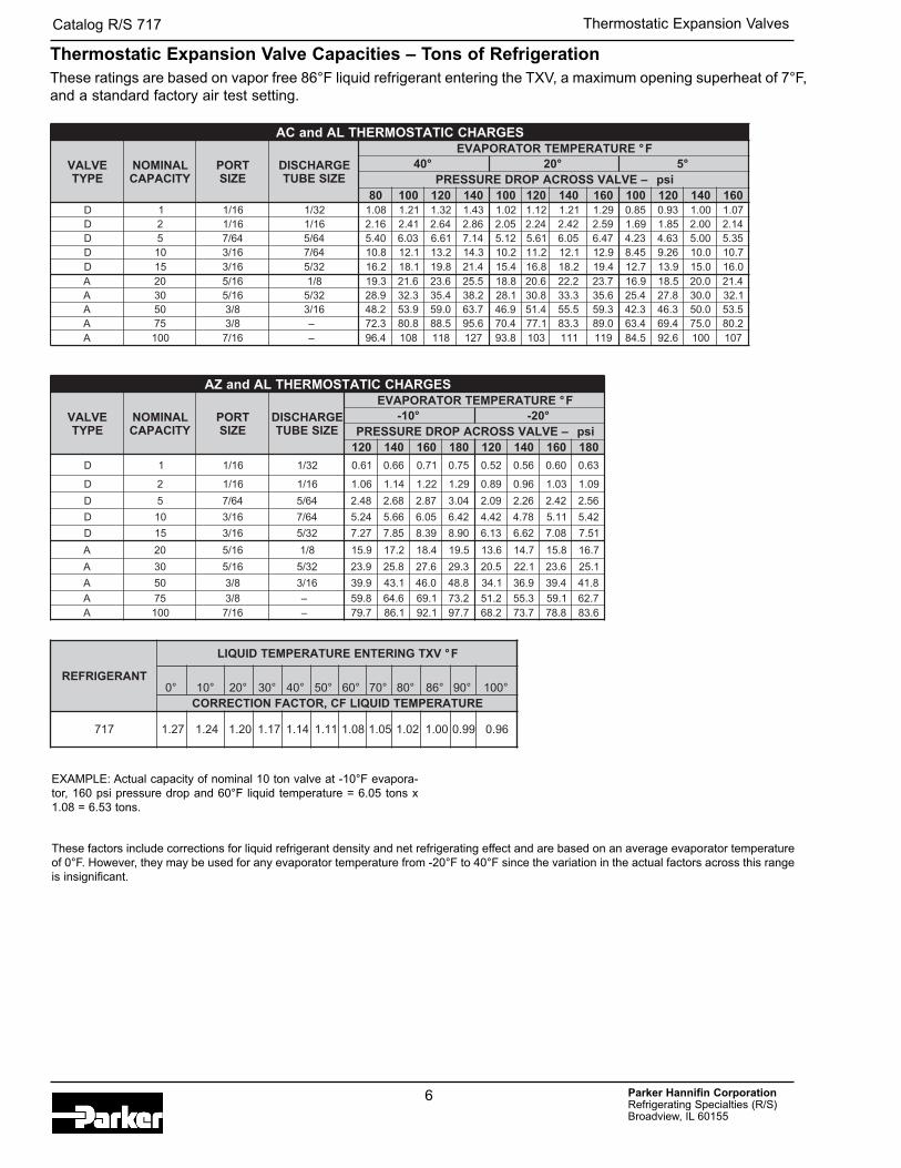
These factors include corrections for liquid refrigerant density and net refrigerating effect and are based on an average evaporator temperatureof 0°F. However, they may be used for any evaporator temperature from -20°F to 40°F since the variation in the actual factors across this rangeis insignificant.
EXAMPLE: Actual capacity of nominal 10 ton valve at -10°F evapora-tor, 160 psi pressure drop and 60°F liquid temperature = 6.05 tons x1.08 = 6.53 tons.
These ratings are based on vapor free 86°F liquid refrigerant entering the TXV, a maximum opening superheat of 7°F, and a standard factory air test setting.
Parker Hannifin CorporationRefrigerating Specialties (R/S) Broadview, IL 60155
Catalog R/S 717
Thermostatic Expansion Valve Capacities – Tons of Refrigeration
6
Thermostatic Expansion Valves
SEGRAHCCITATSOMREHTLAdnaCA
EVLAVEPYT
LANIMONYTICAPAC
TROPEZIS
EGRAHCSIDEZISEBUT
ERUTAREPMETROTAROPAVE F°°04 °02 °5
isp–EVLAVSSORCAPORDERUSSERP08 001 021 041 001 021 041 061 001 021 041 061
D 1 61/1 23/1 80.1 12.1 23.1 34.1 20.1 21.1 12.1 92.1 58.0 39.0 00.1 70.1D 2 61/1 61/1 61.2 14.2 46.2 68.2 50.2 42.2 24.2 95.2 96.1 58.1 00.2 41.2D 5 46/7 46/5 04.5 30.6 16.6 41.7 21.5 16.5 50.6 74.6 32.4 36.4 00.5 53.5D 01 61/3 46/7 8.01 1.21 2.31 3.41 2.01 2.11 1.21 9.21 54.8 62.9 0.01 7.01D 51 61/3 23/5 2.61 1.81 8.91 4.12 4.51 8.61 2.81 4.91 7.21 9.31 0.51 0.61A 02 61/5 8/1 3.91 6.12 6.32 5.52 8.81 6.02 2.22 7.32 9.61 5.81 0.02 4.12A 03 61/5 23/5 9.82 3.23 4.53 2.83 1.82 8.03 3.33 6.53 4.52 8.72 0.03 1.23A 05 8/3 61/3 2.84 9.35 0.95 7.36 9.64 4.15 5.55 3.95 3.24 3.64 0.05 5.35A 57 8/3 – 3.27 8.08 5.88 6.59 4.07 1.77 3.38 0.98 4.36 4.96 0.57 2.08A 001 61/7 – 4.69 801 811 721 8.39 301 111 911 5.48 6.29 001 701
Parker Hannifin CorporationRefrigerating Specialties (R/S) Broadview, IL 60155
Catalog R/S 717
7
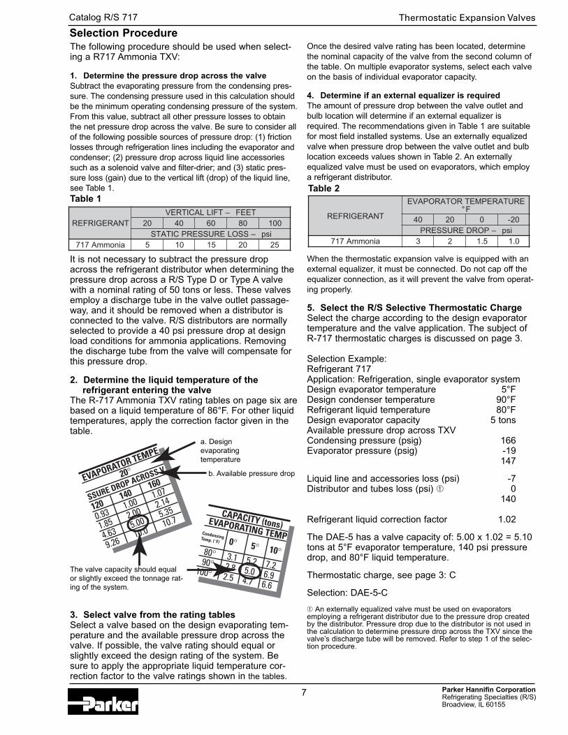
The following procedure should be used when select-ing a R717 Ammonia TXV:
1. Determine the pressure drop across the valveSubtract the evaporating pressure from the condensing pres-sure. The condensing pressure used in this calculation shouldbe the minimum operating condensing pressure of the system.From this value, subtract all other pressure losses to obtainthe net pressure drop across the valve. Be sure to consider allof the following possible sources of pressure drop: (1) frictionlosses through refrigeration lines including the evaporator andcondenser; (2) pressure drop across liquid line accessoriessuch as a solenoid valve and filter-drier; and (3) static pres-sure loss (gain) due to the vertical lift (drop) of the liquid line,see Table 1.
It is not necessary to subtract the pressure dropacross the refrigerant distributor when determining thepressure drop across a R/S Type D or Type A valvewith a nominal rating of 50 tons or less. These valvesemploy a discharge tube in the valve outlet passage-way, and it should be removed when a distributor isconnected to the valve. R/S distributors are normallyselected to provide a 40 psi pressure drop at designload conditions for ammonia applications. Removingthe discharge tube from the valve will compensate forthis pressure drop.
2. Determine the liquid temperature of the refrigerant entering the valve
The R-717 Ammonia TXV rating tables on page six arebased on a liquid temperature of 86°F. For other liquidtemperatures, apply the correction factor given in thetable.
3. Select valve from the rating tablesSelect a valve based on the design evaporating tem-perature and the available pressure drop across thevalve. If possible, the valve rating should equal orslightly exceed the design rating of the system. Besure to apply the appropriate liquid temperature cor-rection factor to the valve ratings shown in the tables.
Once the desired valve rating has been located, determinethe nominal capacity of the valve from the second column ofthe table. On multiple evaporator systems, select each valveon the basis of individual evaporator capacity.
4. Determine if an external equalizer is requiredThe amount of pressure drop between the valve outlet andbulb location will determine if an external equalizer isrequired. The recommendations given in Table 1 are suitablefor most field installed systems. Use an externally equalizedvalve when pressure drop between the valve outlet and bulblocation exceeds values shown in Table 2. An externallyequalized valve must be used on evaporators, which employa refrigerant distributor.
When the thermostatic expansion valve is equipped with anexternal equalizer, it must be connected. Do not cap off theequalizer connection, as it will prevent the valve from operat-ing properly.
5. Select the R/S Selective Thermostatic ChargeSelect the charge according to the design evaporatortemperature and the valve application. The subject ofR-717 thermostatic charges is discussed on page 3.
Selection Example:Refrigerant 717Application: Refrigeration, single evaporator systemDesign evaporator temperature 5°FDesign condenser temperature 90°FRefrigerant liquid temperature 80°FDesign evaporator capacity 5 tonsAvailable pressure drop across TXV Condensing pressure (psig) 166 Evaporator pressure (psig) -19
147
Liquid line and accessories loss (psi) -7Distributor and tubes loss (psi) ➀ 0
140
Refrigerant liquid correction factor 1.02
The DAE-5 has a valve capacity of: 5.00 x 1.02 = 5.10tons at 5°F evaporator temperature, 140 psi pressuredrop, and 80°F liquid temperature.
Thermostatic charge, see page 3: C
Selection: DAE-5-C
➀ An externally equalized valve must be used on evaporatorsemploying a refrigerant distributor due to the pressure drop createdby the distributor. Pressure drop due to the distributor is not used inthe calculation to determine pressure drop across the TXV since thevalve’s discharge tube will be removed. Refer to step 1 of the selec-tion procedure.
Selection Procedure
TNAREGIRFERTEEF–TFILLACITREV
02 04 06 08 001isp–SSOLERUSSERPCITATS
ainommA717 5 01 51 02 52
TNAREGIRFER
ERUTAREPMETROTAROPAVEF°
04 02 0 02-isp–PORDERUSSERP
ainommA717 3 2 5.1 0.1
EVAPORATOR TEMPE
20°
SSURE DROP ACROSS V
120 140
160
0.93 1.00 1.07
1.85 2.00 2.14
4.63 5.00 5.35
9.26 10.0 10.7CAPACITY (tons)EVAPORATING TEMPCondensingTemp. (°F)
80° 3.1 5.2 7.2 90° 2.8 5.0 6.9100° 2.5 4.7 6.6
0° 5° 10°
Table 1Table 2
a. Design evaporating temperature
b. Available pressure drop
The valve capacity should equalor slightly exceed the tonnage rat-ing of the system.
Thermostatic Expansion Valves
Parker Hannifin CorporationRefrigerating Specialties (R/S) Broadview, IL 60155
Catalog R/S 717
Direct Expansion – Steel & Aluminum Models –Flange ConnectionsR/S refrigerant distributors for R-717 function like ourconventional brass models.
Steel models – The distributor body is Type 8620 vacu-um degassed steel. The nozzle is Type 303 stainlesssteel, and the dispersion cone in the distributor ismade of Stellite.
Distributor tube connections are available for 3/16",1/4", and 5/16" OD steel tubing. The ODF connectionsare trepanned to facilitate welding the joint. A 1/8" NPTconnection is also available with Types 1130, 1133,and 1138 distributors.
Aluminum models – These distributors are designedfor R-717 aluminum coils, and they are 6061-T6 alu-minum. As with the steel distributors, the dispersioncone is Stellite, and the nozzle is stainless steel.
Distributor tube connections are available for 3/16",1/4", and 5/16" OD aluminum tubing. Aluminum braz-ing techniques require more space between circuitsthan copper to brass brazing. As a result, the maxi-mum number of circuits is less than for comparablebrass models.
Applying Distributors to Thermostatic Expansion ValvesAll Type D and Type A TXVs up to and including 50tons, employ a discharge tube. The discharge tubereduces refrigerant velocity across the valve port, pre-venting premature pin and seat erosion. When a distrib-utor is used with these valves, the distributor nozzleperforms the discharge tube’s function. The dischargetube must then be removed from the valve to avoidexcessive pressure drop.
Distributor performance is best obtained if the distribu-tor is bolted directly to the TXV outlet. When it is notpossible to bolt the TXV to the distributor, or if a shutoff valve is installed between them, use a short,straight piece of pipe to connect the two. The pipeshould not exceed two feet. It should be sized to main-tain high refrigerant velocities. Elbows between theTXV and distributor are not recommended since theyhinder proper distribution.
Ratings for Refrigerant 717 DistributorsFull load ratings are based on 30 psi nozzle, 10 psitube pressure drop and 86° liquid temperature enteringthermostatic expansion valve.
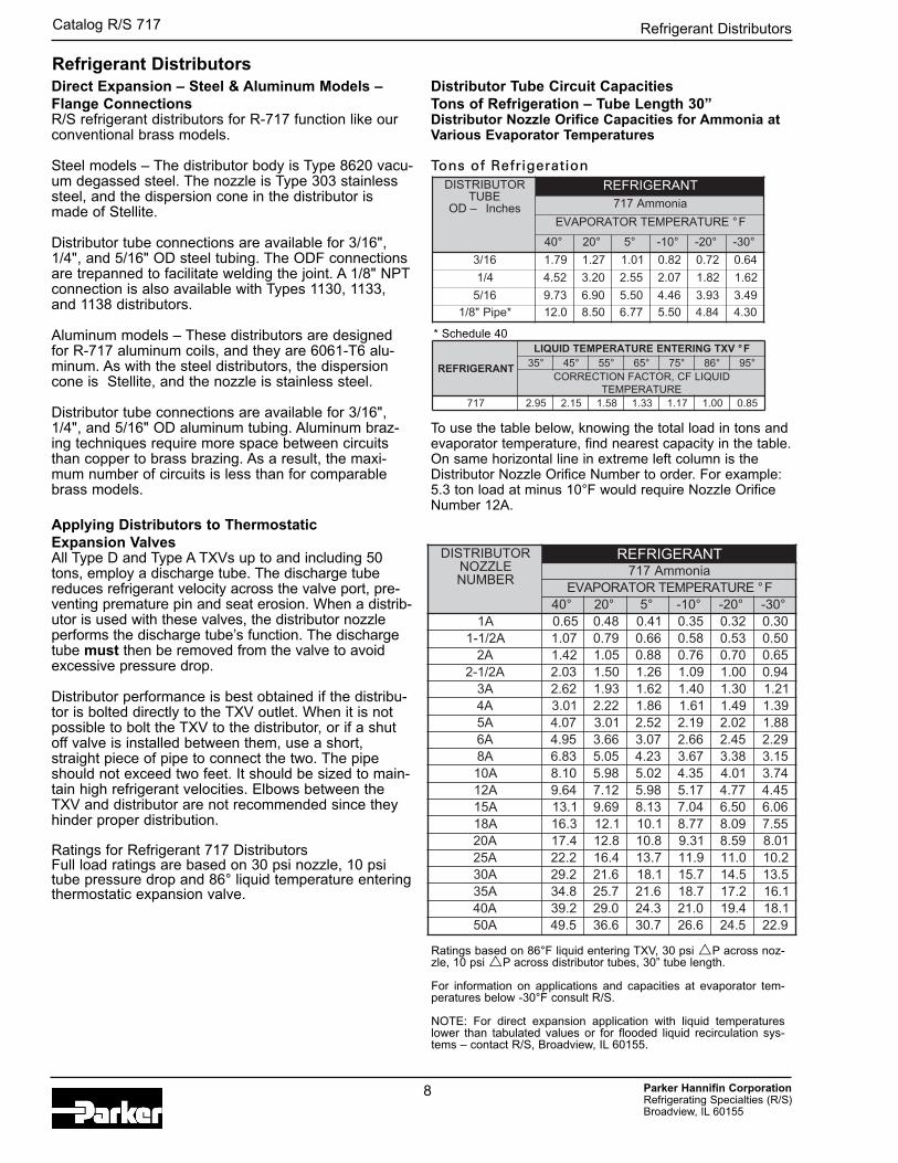
Distributor Tube Circuit Capacities Tons of Refrigeration – Tube Length 30”Distributor Nozzle Orifice Capacities for Ammonia atVarious Evaporator Temperatures
Tons of Refrigeration
To use the table below, knowing the total load in tons andevaporator temperature, find nearest capacity in the table.On same horizontal line in extreme left column is theDistributor Nozzle Orifice Number to order. For example:5.3 ton load at minus 10°F would require Nozzle OrificeNumber 12A.
Refrigerant Distributors
ROTUBIRTSIDEBUT
–DO sehcnI
TNAREGIRFERainommA717
ERUTAREPMETROTAROPAVE F°
°04 °02 °5 °01- °02- °03-
61/3 97.1 72.1 10.1 28.0 27.0 46.0
4/1 25.4 02.3 55.2 70.2 28.1 26.1
61/5 37.9 09.6 05.5 64.4 39.3 94.3
*epiP"8/1 0.21 05.8 77.6 05.5 48.4 03.4
ROTUBIRTSIDELZZONREBMUN
TNAREGIRFERainommA717
ERUTAREPMETROTAROPAVE F°°04 °02 °5 °01- °02- °03-
A1 56.0 84.0 14.0 53.0 23.0 03.0A2/1-1 70.1 97.0 66.0 85.0 35.0 05.0
A2 24.1 50.1 88.0 67.0 07.0 56.0A2/1-2 30.2 05.1 62.1 90.1 00.1 49.0
A3 26.2 39.1 26.1 04.1 03.1 12.1A4 10.3 22.2 68.1 16.1 94.1 93.1A5 70.4 10.3 25.2 91.2 20.2 88.1A6 59.4 66.3 70.3 66.2 54.2 92.2A8 38.6 50.5 32.4 76.3 83.3 51.3A01 01.8 89.5 20.5 53.4 10.4 47.3A21 46.9 21.7 89.5 71.5 77.4 54.4A51 1.31 96.9 31.8 40.7 05.6 60.6A81 3.61 1.21 1.01 77.8 90.8 55.7A02 4.71 8.21 8.01 13.9 95.8 10.8A52 2.22 4.61 7.31 9.11 0.11 2.01A03 2.92 6.12 1.81 7.51 5.41 5.31A53 8.43 7.52 6.12 7.81 2.71 1.61A04 2.93 0.92 3.42 0.12 4.91 1.81A05 5.94 6.63 7.03 6.62 5.42 9.22
TNAREGIRFER
VXTGNIRETNEERUTAREPMETDIUQIL F°°53 °54 °55 °56 °57 °68 °59
DIUQILFC,ROTCAFNOITCERROCERUTAREPMET
717 59.2 51.2 85.1 33.1 71.1 00.1 58.0
Ratings based on 86°F liquid entering TXV, 30 psi �P across noz-zle, 10 psi �P across distributor tubes, 30” tube length.
For information on applications and capacities at evaporator tem-peratures below -30°F consult R/S.
NOTE: For direct expansion application with liquid temperatureslower than tabulated values or for flooded liquid recirculation sys-tems – contact R/S, Broadview, IL 60155.
* Schedule 40
8
Refrigerant Distributors
SNOITACIFICEPSSTIUCRIC.ONSEZISGNIBUT&
ELBALIAVA
ELZZONECIFIROSREBMUNELBALIAVA
&ELZZONRENIATEREZISGNIR
ROTUBIRTSIDSNOISNEMID
sehcnI
A B C D E F G
2311EPYT leetS -thgieWteN.zo9yletamixorppA
GnoitanibmocnidesU
evlaVS/RhtiwdnaEADepyT
,EADroreniartSDXdnareniartSDX
,evlaVdioneloS3A5AMleetS,reniartSDXrodna056702.oNegnalF.256702.oNtraPrecapS
44.2 21.1 73.1 52.0 ➀ – –
-5ot2 dedleWFDO-"61/3
A03urhtA1-4ot2 dedleWFDO-"4/1
-3ot2 dedleWFDO-"61/5
0811EPYT munimulA -thgieWteN.zo4yletamixorppA
-8ot2 gnizarBFDO-"61/3A03urhtA1
-6ot2 gnizarBFDO-"4/1
0311EPYT leetS -thgieWteN.zo01,.bl1yletamixorppA
GnoitanibmocnidesU
evlaVS/RhtiwdnaEADepyT
,EADroreniartSDXdnareniartSDX
,evlaVdioneloS3A5AMhtiwreniartSDXro
.256702.oNtraPrecapS
05.2 52.2 57.2 00.2 ➁
52.0 05.0
-01ot2 dedleWFDO-"61/3
A03urhtA1-01ot4 dedleWFDO-"4/1
-6ot2 dedleWFDO-"61/5
-6ot2 TPN-"8/1
2811EPYT munimulA -thgieWteN.zo01yletamixorppA
21.0 26.0-21ot8 gnizarBFDO-"61/3A03urhtA1
-01ot7 gnizarBFDO-"4/1
8311EPYT leetS -thgieWteN.zo6,.bl3yletamixorppA
CnoitanibmocnidesU
evlaVS/RhtiwdnaEAAepyT
,EAAroreniartS4008dnareniartS4008
,evlaVdioneloS3A71AMhtiwreniartS4008ro
.356702.oNtraPrecapS
78.2 91.360.3
84.305.3 96.2 ➁ 52.0 57.0
-91ot11 dedleWFDO-"61/3
A05urhtA5-41ot6 dedleWFDO-"4/1
-21ot7 dedleWFDO-"61/5
-01ot2 TPN-"8/1
5811EPYT munimulA -thgieWteN.zo4,.bl1yletamixorppA
-02ot8 gnizarBFDO-"61/3
A05urhtA5-61ot6 gnizarBFDO-"4/1
-11ot2 gnizarBFDO-"61/5
Parker Hannifin CorporationRefrigerating Specialties (R/S) Broadview, IL 60155
Catalog R/S 717
9
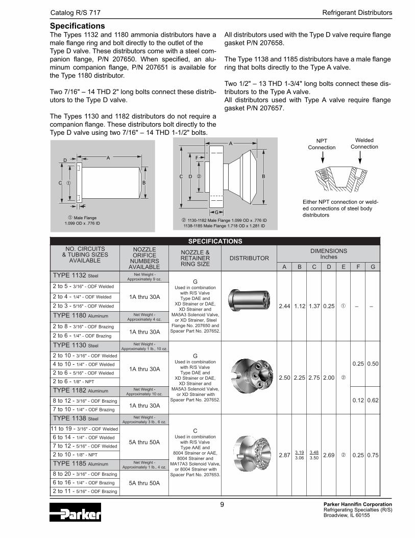
The Types 1132 and 1180 ammonia distributors have amale flange ring and bolt directly to the outlet of the Type D valve. These distributors come with a steel com-panion flange, P/N 207650. When specified, an alu-minum companion flange, P/N 207651 is available forthe Type 1180 distributor.
Two 7/16" – 14 THD 2" long bolts connect these distrib-utors to the Type D valve.
The Types 1130 and 1182 distributors do not require acompanion flange. These distributors bolt directly to theType D valve using two 7/16" – 14 THD 1-1/2" bolts.
All distributors used with the Type D valve require flangegasket P/N 207658.
The Type 1138 and 1185 distributors have a male flangering that bolts directly to the Type A valve.
Two 1/2" – 13 THD 1-3/4" long bolts connect these dis-tributors to the Type A valve.All distributors used with Type A valve require flangegasket P/N 207657.
A
BC
D
A
BC D
F
G
➀
➀ Male Flange1.099 OD x .776 ID
➁ 1130-1182 Male Flange 1.099 OD x .776 ID1138-1185 Male Flange 1.718 OD x 1.281 ID
➁
F
NPTConnection
WeldedConnection
Either NPT connection or weld-ed connections of steel bodydistributors
Specifications
Refrigerant Distributors
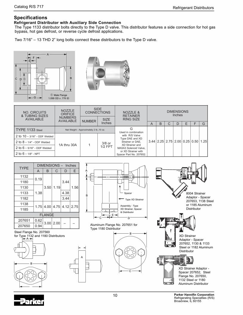
The Type 1133 distributor bolts directly to the Type D valve. This distributor features a side connection for hot gasbypass, hot gas defrost, or reverse cycle defrost applications.
Two 7/16” – 13 THD 2” long bolts connect these distributors to the Type D valve.
SpecificationsRefrigerant Distributor with Auxiliary Side Connection
STIUCRIC.ONSEZISGNIBUT&
ELBALIAVA
ELZZONECIFIROSREBMUNELBALIAVA
EDISSNOITCENNOC &ELZZON
RENIATEREZISGNIR
SNOISNEMIDsehcnI
REBMUN EZISsehcnI A B C D E F G
3311EPYT leetS .zo01,.bl2yletamixorppA-thgieWteN GnoitanibmocnidesU
evlaVS/RhtiwDXdnaEADepyT,EADroreniartS
dnareniartSDX,evlaVdioneloS3A5AM
htiwreniartSDXro.256702.oNtraPrecapS
44.3 52.2 57.2 00.2 52.0 05.0 52.1
-01ot2 dedleWFDO-"61/3
A03urhtA1 1 ro8/3TPF2/1
-8ot2 dedleWFDO-"4/1
-6ot2 dedleWFDO-"61/5
-6ot2 TPN-"8/1
EPYT–SNOISNEMID sehcnI
A B C D E
231191.0
05.3 91.1
44.3
65.1
0811
0311
83.13311 83.4
2811 44.3
831157.1 00.4 57.4 21.4 57.2
5811
EGNALF
156702 26.000.3 00.2 – –
056702 49.0
Parker Hannifin CorporationRefrigerating Specialties (R/S) Broadview, IL 60155
Catalog R/S 717
10
A
SpacerB
C DE
Type XD Strainer
Assembly - Type XD Strainer, Spacer & Distributor
XD Strainer Adaptor - Spacer207652, 1130 & 1133Steel or 1182 AluminumDistributor
XD Strainer Adaptor -Spacer 207652, SteelFlange No. 207650,1132 Steel or 1180Aluminum Distributor
A
B
C
A
B
C
A
B
FE
C D
G➀ Male Flange
1.099 OD x .776 ID
➀
Steel Flange No. 207560 for Type 1132 and 1180 Distributors
Aluminum Flange No. 207651 forType 1180 Distributor
Refrigerant Distributors
8004 Strainer Adaptor - Spacer207653, 1138 Steel or 1185 AluminumDistributor
Parker Hannifin CorporationRefrigerating Specialties (R/S) Broadview, IL 60155
Catalog R/S 717
11
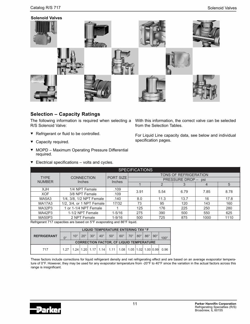
Selection – Capacity Ratings
SNOITACIFICEPS
EPYTREBMUN
NOITCENNOCsehcnI
EZISTROPsehcnI
NOITAREGIRFERFOSNOTisp–PORDERUSSERP
1 2 3 4 5HJX elameFTPN4/1 901.
19.3 45.5 97.6 58.7 87.8FOX elameFTPN8/3 901.
3A5AM elameFTPN2/1,8/3,4/1 041. 0.8 3.11 7.31 61 8.713A71AM elameFTPN1ro,4/3,2/1 23/71 37 59 021 341 0613P23AM elameFTPN4/1-1ro1 1 521 671 522 052 0823P24AM elameFTPN2/1-1 61/5-1 572 093 005 055 5263P05AM elameFTPN2 61/9-1 005 527 578 0001 0111
TNAREGIRFER
VXTGNIRETNEERUTAREPMETDIUQIL F°
°0°01 °02 °03 °04 °05 °06 °07 °08 °68 °09
°001ERUTAREPMETDIUQILFC,ROTCAFNOITCERROC
717 72.1 42.1 02.1 71.1 41.1 11.1 80.1 50.1 20.1 00.1 99.0 69.0
These factors include corrections for liquid refrigerant density and net refrigerating effect and are based on an average evaporator tempera-ture of 0°F. However, they may be used for any evaporator temperature from -20°F to 40°F since the variation in the actual factors across thisrange is insignificant.
Refrigerant 717 capacities are based on 5°F evaporating and 86°F liquid.
Solenoid Valves
The following information is required when selecting aR/S Solenoid Valve:
� Refrigerant or fluid to be controlled.
� Capacity required.
� MOPD – Maximum Operating Pressure Differentialrequired.
� Electrical specifications – volts and cycles.
With this information, the correct valve can be selectedfrom the Selection Tables.
For Liquid Line capacity data, see below and individualspecification pages.
Solenoid Valves
LIOC1-CKM–SNOITACIFICEPS
EPYTDRADNATS
SNOITCENNOCsehcnI
EZISTROPsehcnI
DPOMisp
DIUQILLANIMONSEITICAPAC fosnoT
noitaregirfeR SGNITARLIOCDRADNATSAINOMMA
isp–PORDERUSSERP
CA 1 2 3 4 5 -CYC/STLOVSEL STTAW
HJX elameFTPN4/1
901. 052 19.3 45.5 97.6 58.7 87.8
06-05/4206-05/02106-05/80206-05/042-021lauD
06/042
01
FOX elameFTPN8/3
� Safe working pressure 300 psi. � Dual voltage 4-wire coils, 120-240/60 are available at slight additional cost.
For other voltages and cycles, consult R/S. � Available with conduit boss or junction box at no extra charge.
Parker Hannifin CorporationRefrigerating Specialties (R/S) Broadview, IL 60155
Catalog R/S 717
12
1.56 Coil Removal
2.22
2.92
1.88
0.50
1.60
Optional 1/2” Conduit Boss
45°1.00
Mounting Hole Pattern#8-32 x .31 Deep
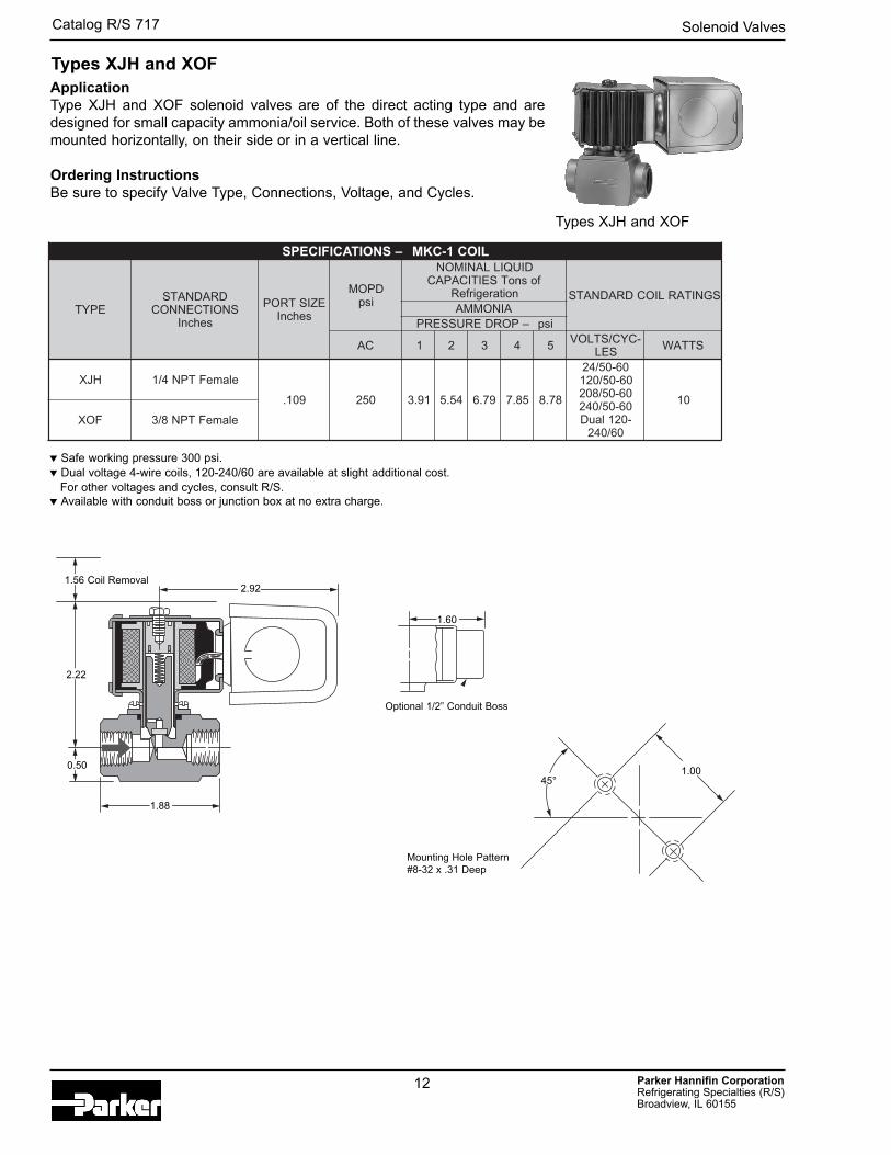
ApplicationType XJH and XOF solenoid valves are of the direct acting type and aredesigned for small capacity ammonia/oil service. Both of these valves may bemounted horizontally, on their side or in a vertical line.
Ordering InstructionsBe sure to specify Valve Type, Connections, Voltage, and Cycles.
Types XJH and XOF
Types XJH and XOF
Solenoid Valves
Parker Hannifin CorporationRefrigerating Specialties (R/S) Broadview, IL 60155
Catalog R/S 717
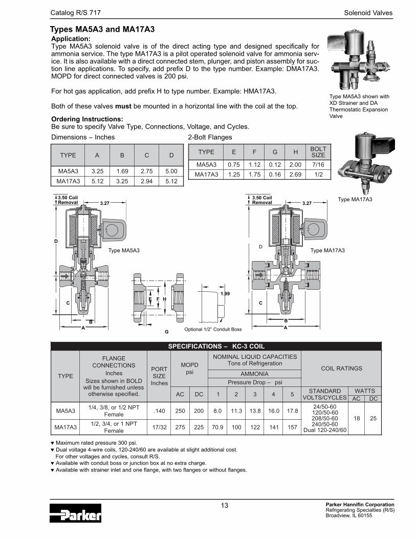
EPYT A B C D
3A5AM 52.3 96.1 57.2 00.5
3A71AM 21.5 52.3 49.2 21.5
EPYT E F G H TLOBEZIS
3A5AM 57.0 21.1 21.0 00.2 61/7
3A71AM 52.1 57.1 61.0 96.2 2/1
LIOC3-CK–SNOITACIFICEPS
EPYT
EGNALFSNOITCENNOC
sehcnIninwohsseziS DLOB
sselnudehsinrufeblliw.deificepsesiwrehto
TROPEZISsehcnI
DPOMisp
SEITICAPACDIUQILLANIMONnoitaregirfeRfosnoT
SGNITARLIOCAINOMMA
isp–porDerusserP
CA CD 1 2 3 4 5 DRADNATSSELCYC/STLOV
STTAWCA CD
3A5AMro,8/3,4/1 2/1 TPN
elameF041. 052 002 0.8 3.11 8.31 0.61 8.71
06-05/4206-05/02106-05/80206-05/042
06/042-021lauD
81 52
3A71AM,2/1 ,4/3 TPN1ro
elameF23/71 572 522 9.07 001 221 141 751
3.50 Coil Removal
D
3.27
C
BA
E F H
G
1.99
3.50 Coil Removal
Application:Type MA5A3 solenoid valve is of the direct acting type and designed specifically forammonia service. The type MA17A3 is a pilot operated solenoid valve for ammonia serv-ice. It is also available with a direct connected stem, plunger, and piston assembly for suc-tion line applications. To specify, add prefix D to the type number. Example: DMA17A3.MOPD for direct connected valves is 200 psi.
For hot gas application, add prefix H to type number. Example: HMA17A3.
Both of these valves must be mounted in a horizontal line with the coil at the top.
Ordering Instructions:Be sure to specify Valve Type, Connections, Voltage, and Cycles.
Dimensions – Inches 2-Bolt Flanges
3.27
D
C
B
A
� Maximum rated pressure 300 psi. � Dual voltage 4-wire coils, 120-240/60 are available at slight additional cost.
For other voltages and cycles, consult R/S. � Available with conduit boss or junction box at no extra charge.� Available with strainer inlet and one flange, with two flanges or without flanges.
Type MA5A3 shown withXD Strainer and DAThermostatic ExpansionValve
Type MA17A3
Type MA17A3 Type MA5A3
Optional 1/2” Conduit Boss
Types MA5A3 and MA17A3
13
Solenoid Valves
Parker Hannifin CorporationRefrigerating Specialties (R/S) Broadview, IL 60155
Catalog R/S 717
14
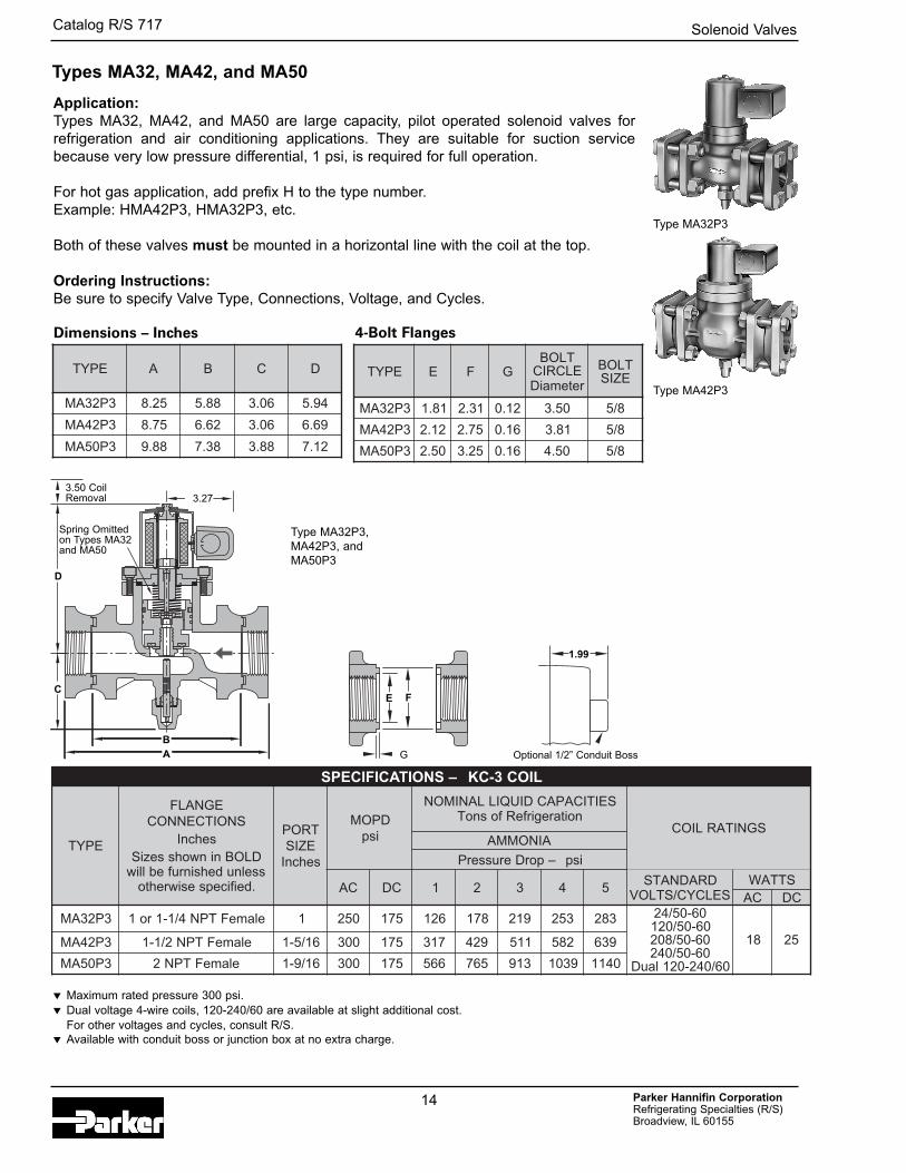
EPYT E F GTLOBELCRICretemaiD
TLOBEZIS
3P23AM 18.1 13.2 21.0 05.3 8/5
3P24AM 21.2 57.2 61.0 18.3 8/5
3P05AM 05.2 52.3 61.0 05.4 8/5
EPYT A B C D
3P23AM 52.8 88.5 60.3 49.5
3P24AM 57.8 26.6 60.3 96.6
3P05AM 88.9 83.7 88.3 21.7
LIOC3-CK–SNOITACIFICEPS
EPYT
EGNALFSNOITCENNOC
sehcnIninwohsseziS DLOB
sselnudehsinrufeblliw.deificepsesiwrehto
TROPEZISsehcnI
DPOMisp
SEITICAPACDIUQILLANIMONnoitaregirfeRfosnoT
SGNITARLIOCAINOMMA
isp–porDerusserP
CA CD 1 2 3 4 5 DRADNATSSELCYC/STLOV
STTAWCA CD
3P23AM ro1 4/1-1 elameFTPN 1 052 571 621 871 912 352 382 06-05/4206-05/02106-05/80206-05/042
06/042-021lauD
81 523P24AM elameFTPN2/1-1 61/5-1 003 571 713 924 115 285 936
3P05AM elameFTPN2 61/9-1 003 571 665 567 319 9301 0411
Application:Types MA32, MA42, and MA50 are large capacity, pilot operated solenoid valves forrefrigeration and air conditioning applications. They are suitable for suction servicebecause very low pressure differential, 1 psi, is required for full operation.
For hot gas application, add prefix H to the type number. Example: HMA42P3, HMA32P3, etc.
Both of these valves must be mounted in a horizontal line with the coil at the top.
Ordering Instructions:Be sure to specify Valve Type, Connections, Voltage, and Cycles.
Dimensions – Inches 4-Bolt Flanges
� Maximum rated pressure 300 psi.� Dual voltage 4-wire coils, 120-240/60 are available at slight additional cost.
For other voltages and cycles, consult R/S. � Available with conduit boss or junction box at no extra charge.
Type MA32P3
Type MA42P3
Type MA32P3,MA42P3, and MA50P3
Optional 1/2” Conduit Boss
D
3.27
C
BA
E F
G
1.99
3.50 Coil Removal
Spring Omittedon Types MA32and MA50
Types MA32, MA42, and MA50
Solenoid Valves
Parker Hannifin CorporationRefrigerating Specialties (R/S) Broadview, IL 60155
Catalog R/S 717
15
SNOITACIFICEPS
EPYT SNOITCENNOCTPFsehcnI
FO.ONSEROC
EROCTRAP.ON
FOEMULOVTNACCISED
.nI.uC
GNITNUOMSTEKCARB
SNOISNEMIDLLEHSsehcnI
TENTHGIEW
.sbL
GNIPPIHSTHGIEW
.sbLA B C D E F G P*P-484-CP-669-CP-8441-CP-21291-C
2/14/3
1 2/1-2/1-1
1234
4684-CR
8469441291
586-A
1 80.976.4124.0258.52
00.6 00.5
1 58.544.1191.7126.22
14.384.366.367.3
57.4 –
1 05.700.3126.8152.42
01417102
21610232
P-61004-C 2 2/1- 4 -9001-CR8 004 2-571-A 44.43 05.7 52.6 83.03 83.4 00.6 – 21.23 64 15
RETLIFREYRD
EPYT
GNITTIFEZISTPF
NOITCELESSNOITADNEMMOCER
snoT
TNAREGIRFERWOLF
YTICAPACisp1tasnoT
P∆
ELBAECALPEREPYTEROC
YTITNAUQDNADERIUQER
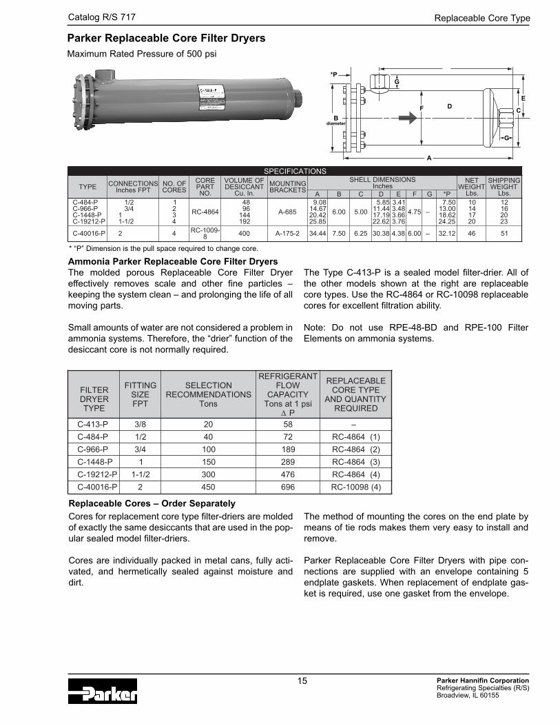
P-314-C 8/3 02 85 –
P-484-C 2/1 04 27 )1(4684-CR
P-669-C 4/3 001 981 )2(4684-CR
P-8441-C 1 051 982 )3(4684-CR
P-21291-C 2/1-1 003 674 )4(4684-CR
P-61004-C 2 054 696 )4(89001-CR
Parker Replaceable Core Filter Dryers
* “P” Dimension is the pull space required to change core.
Ammonia Parker Replaceable Core Filter DryersThe molded porous Replaceable Core Filter Dryereffectively removes scale and other fine particles –keeping the system clean – and prolonging the life of allmoving parts.
Small amounts of water are not considered a problem inammonia systems. Therefore, the “drier” function of thedesiccant core is not normally required.
The Type C-413-P is a sealed model filter-drier. All ofthe other models shown at the right are replaceablecore types. Use the RC-4864 or RC-10098 replaceablecores for excellent filtration ability.
Note: Do not use RPE-48-BD and RPE-100 FilterElements on ammonia systems.
Cores for replacement core type filter-driers are moldedof exactly the same desiccants that are used in the pop-ular sealed model filter-driers.
Cores are individually packed in metal cans, fully acti-vated, and hermetically sealed against moisture anddirt.
The method of mounting the cores on the end plate bymeans of tie rods makes them very easy to install andremove.
Parker Replaceable Core Filter Dryers with pipe con-nections are supplied with an envelope containing 5endplate gaskets. When replacement of endplate gas-ket is required, use one gasket from the envelope.
Replaceable Cores – Order Separately
D
Bdiameter
A
F
E
G
C
*P
Maximum Rated Pressure of 500 psi
G
Replaceable Core Type
Parker Hannifin CorporationRefrigerating Specialties (R/S) Broadview, IL 60155
Catalog R/S 717
SNOITACIFICEPS
EPYT.ON
SNOITCENNOCsehcnI NEERCS
HSEMEZIS
–THGIEW.sbL –SNOISNEMID sehcnI
TELNI TELTUO AERA.nI.qS
TRAP.ON TEN -PIHS
GNIP A B C E F G H K L
470DX 2/1 TPF egnalF 6.6 3-536 001 4/3-1 3 91.4 05.1 52.2 88.2 00.2 87.0 90.1 05.0 31.0
SNOITACIFICEPS
EPYT.ON
NOITCENNOCsehcnI
NEERCS -SEMH
EZIS
THGIEW.sbL –SNOISNEMID sehcnI
AERA.nI.qS
TRAP.ON TEN -PIHS
GNIP A B C D E F G H K L
4008 2/1 *TPF51 3-7904 08 5 7 96.5 57.2 60.5 60.2 18.3 96.2 82.1 57.1 65.0
31.06008 *TPF4/3
8009 **TPF132 3-0114 06
1131 65.7 31.3 05.7 – 44.2 57.3 18.1 13.2 57.0
0109 -1 4/1 **TPF -01 2/1
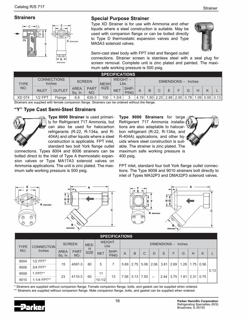
Strainers Special Purpose StrainerType XD Strainer is for use with Ammonia and otherliquids where a steel construction is suitable. May beused with companion flange or can be bolted directlyto Type D thermostatic expansion valves and TypeMA5A3 solenoid valves.
Semi-cast steel body with FPT inlet and flanged outletconnections. Strainer screen is stainless steel with a seal plug forscreen removal. Complete unit is zinc plated and painted. The maxi-mum safe working pressure is 500 psig.
“Y” Type Cast Semi-Steel Strainers
Type 8000 Strainer is used primari-ly for Refrigerant 717 Ammonia, butcan also be used for halocarbonrefrigerants (R-22, R-134a, and R-404A) and other liquids where a steelconstruction is applicable. FPT inlet,standard two bolt York flange outlet
connections. Types 8004 and 8006 strainers can bebolted direct to the inlet of Type A thermostatic expan-sion valves or Type MA17A3 solenoid valves onAmmonia applications. The unit is zinc plated. The max-imum safe working pressure is 500 psig.
Type 9000 Strainers for largeRefrigerant 717 Ammonia installa-tions are also adaptable to halocar-bon refrigerant (R-22, R-134a, andR-404A) applications, and other liq-uids where steel construction is suit-able. The strainer is zinc plated. Themaximum safe working pressure is400 psig.
FPT inlet, standard four bolt York flange outlet connec-tions. The Type 9008 and 9010 strainers bolt directly toinlet of Types MA32P3 and DMA32P3 solenoid valves.
* Strainers are supplied without companion flange. Female companion flange, bolts, and gasket can be supplied when ordered.** Strainers are supplied without companion flange. Male companion flange, bolts, and gasket can be supplied when ordered.
C L
G H
E
A
F
K diameter
Bdiameter
IN
A
C
D H G
E AF
K diameter
Bdiameter
C
H G
EF
K diameter
Bdiameter
E F
L L
16
Strainers are supplied with female companion flange. Strainers can be ordered without the flange.
Strainer
The R/S Level-Master Control is a positive liquid level con-trol device suitable for application to all flooded evapora-tors.
Description and OperationThe LMC is a standard thermostatic expansion valveequipped with a Level-Master Element. The combinationprovides a simple, economical, and highly effective liquidlevel control. The bulb of the conventional thermostatic ele-ment has been modified to an insert type of bulb that incor-porates a low wattage heater. A 15-watt heater is suppliedas standard. For applications below -60°F evaporatingtemperature, specify a special 25-watt heater.
The insert bulb is installed in the accumulator or surgedrum at the point of the desired liquid level. As the level atthe insert bulb drops, the electrically added heat increas-es the pressure within the thermostatic element andopens the valve. As the liquid level at the bulb rises, theelectrical input is balanced by the heat transfer from thebulb to the liquid refrigerant and the LMC either modulatesor eventually shuts off. The evaporator pressure andspring assist in providing a positive closure.
Installation – GeneralThe Level-Master Control is applicable to any systemthat has been specifically designed for flooded oper-ation.R/S is not responsible for system design and, therefore, isnot liable for any damage arising from faulty design orimproper piping, or for misapplication of its products.Figures 2 through 4 are piping schematics only to illustratepossible methods of applying the LMC valves.
If these valves are applied in any manner other than asdescribed in this bulletin, the R/S warranty is void. Actualsystem piping must be done to protect the compressor atall times. This includes protection against overheating,slugging with liquid refrigerant, and trapping of oil in vari-ous locations. R/S recommends that recognized pipingreferences, such as equipment manufacturers’ literatureand the ASHRAE Guide and Data Book, be consulted forassistance with this subject.
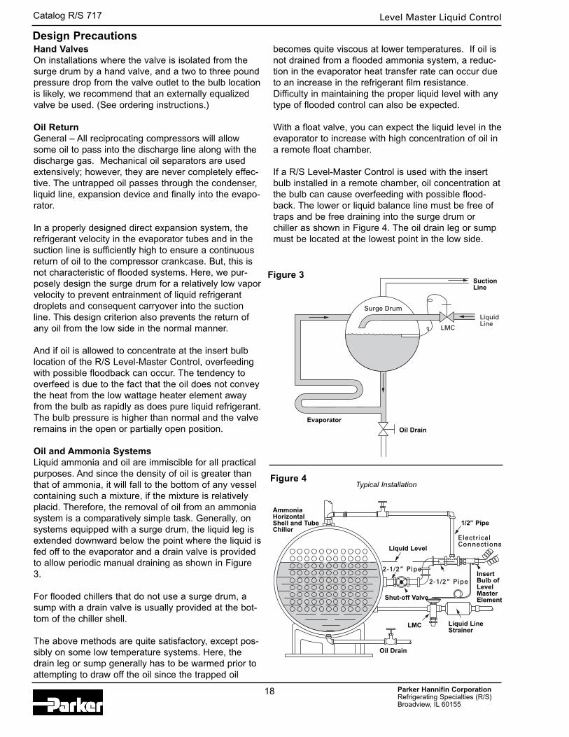
The valve is usually connected to feed into the surge drumabove the liquid level. It can also feed into the liquid leg orcoil header.
The insert bulb can be installed directly into the shell,surge drum or liquid leg on new or existing installations.Existing float systems can be easily converted by installingthe LMC insert bulb in the float chamber.The Level-Master Control may be installed at any ambienttemperature. The element is protected against excessivetemperature, created by the heater, by a thermostaticswitch that is an integral part of the heater assembly.
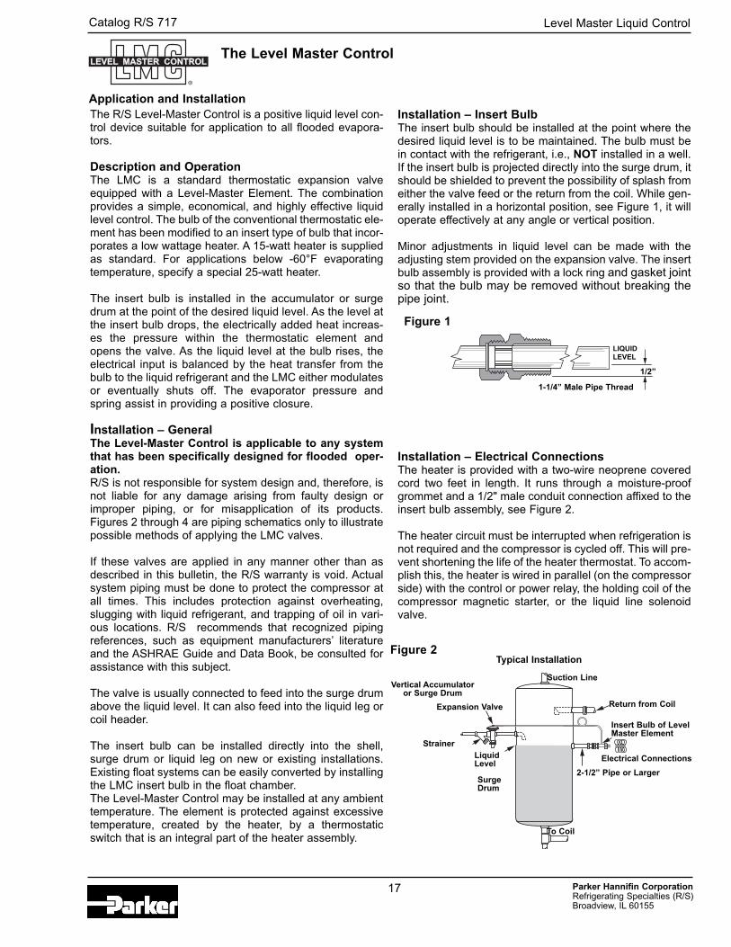
Installation – Insert BulbThe insert bulb should be installed at the point where thedesired liquid level is to be maintained. The bulb must bein contact with the refrigerant, i.e., NOT installed in a well.If the insert bulb is projected directly into the surge drum, itshould be shielded to prevent the possibility of splash fromeither the valve feed or the return from the coil. While gen-erally installed in a horizontal position, see Figure 1, it willoperate effectively at any angle or vertical position.
Minor adjustments in liquid level can be made with theadjusting stem provided on the expansion valve. The insertbulb assembly is provided with a lock ring and gasket jointso that the bulb may be removed without breaking thepipe joint.
Installation – Electrical ConnectionsThe heater is provided with a two-wire neoprene coveredcord two feet in length. It runs through a moisture-proofgrommet and a 1/2" male conduit connection affixed to theinsert bulb assembly, see Figure 2.
The heater circuit must be interrupted when refrigeration isnot required and the compressor is cycled off. This will pre-vent shortening the life of the heater thermostat. To accom-plish this, the heater is wired in parallel (on the compressorside) with the control or power relay, the holding coil of thecompressor magnetic starter, or the liquid line solenoidvalve.
17 Parker Hannifin CorporationRefrigerating Specialties (R/S) Broadview, IL 60155
Catalog R/S 717
Application and Installation
The Level Master Control
Figure 1
1/2”
1-1/4” Male Pipe Thread
LIQUIDLEVEL
Figure 2
Suction Line
Strainer
Return from Coil
Insert Bulb of LevelMaster Element
Electrical Connections
2-1/2” Pipe or Larger
Expansion Valve
LiquidLevel
SurgeDrum
To Coil
Typical Installation
Vertical Accumulatoror Surge Drum
Level Master Liquid Control
Parker Hannifin CorporationRefrigerating Specialties (R/S) Broadview, IL 60155
Catalog R/S 717
18
Hand ValvesOn installations where the valve is isolated from thesurge drum by a hand valve, and a two to three poundpressure drop from the valve outlet to the bulb locationis likely, we recommend that an externally equalizedvalve be used. (See ordering instructions.)
Oil ReturnGeneral – All reciprocating compressors will allowsome oil to pass into the discharge line along with thedischarge gas. Mechanical oil separators are usedextensively; however, they are never completely effec-tive. The untrapped oil passes through the condenser,liquid line, expansion device and finally into the evapo-rator.
In a properly designed direct expansion system, therefrigerant velocity in the evaporator tubes and in thesuction line is sufficiently high to ensure a continuousreturn of oil to the compressor crankcase. But, this isnot characteristic of flooded systems. Here, we pur-posely design the surge drum for a relatively low vaporvelocity to prevent entrainment of liquid refrigerantdroplets and consequent carryover into the suctionline. This design criterion also prevents the return ofany oil from the low side in the normal manner.
And if oil is allowed to concentrate at the insert bulblocation of the R/S Level-Master Control, overfeedingwith possible floodback can occur. The tendency tooverfeed is due to the fact that the oil does not conveythe heat from the low wattage heater element awayfrom the bulb as rapidly as does pure liquid refrigerant.The bulb pressure is higher than normal and the valveremains in the open or partially open position.
Oil and Ammonia SystemsLiquid ammonia and oil are immiscible for all practicalpurposes. And since the density of oil is greater thanthat of ammonia, it will fall to the bottom of any vesselcontaining such a mixture, if the mixture is relativelyplacid. Therefore, the removal of oil from an ammoniasystem is a comparatively simple task. Generally, onsystems equipped with a surge drum, the liquid leg isextended downward below the point where the liquid isfed off to the evaporator and a drain valve is providedto allow periodic manual draining as shown in Figure3.
For flooded chillers that do not use a surge drum, asump with a drain valve is usually provided at the bot-tom of the chiller shell.
The above methods are quite satisfactory, except pos-sibly on some low temperature systems. Here, thedrain leg or sump generally has to be warmed prior toattempting to draw off the oil since the trapped oil
becomes quite viscous at lower temperatures. If oil isnot drained from a flooded ammonia system, a reduc-tion in the evaporator heat transfer rate can occur dueto an increase in the refrigerant film resistance.Difficulty in maintaining the proper liquid level with anytype of flooded control can also be expected.
With a float valve, you can expect the liquid level in theevaporator to increase with high concentration of oil ina remote float chamber.
If a R/S Level-Master Control is used with the insertbulb installed in a remote chamber, oil concentration atthe bulb can cause overfeeding with possible flood-back. The lower or liquid balance line must be free oftraps and be free draining into the surge drum orchiller as shown in Figure 4. The oil drain leg or sumpmust be located at the lowest point in the low side.
Design Precautions
SuctionLine
LiquidLine
Surge Drum
Evaporator
Oil Drain
LMC
Figure 3
1/2” Pipe
ElectricalConnections
AmmoniaHorizontalShell and TubeChiller
InsertBulb ofLevelMasterElement
Oil Drain
LMC
Figure 4
Liquid Level
2-1/2” Pipe
2-1/2” Pipe
Shut-off Valve
Liquid LineStrainer
Typical Installation
Level Master Liquid Control
Parker Hannifin CorporationRefrigerating Specialties (R/S) Broadview, IL 60155
Catalog R/S 717
19
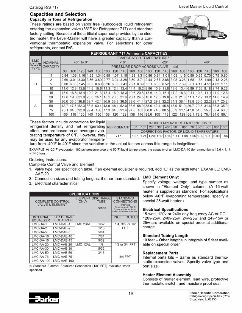
Capacity in Tons of RefrigerationThese ratings are based on vapor free (subcooled) liquid refrigerantentering the expansion valve (86°F for Refrigerant 717) and standardfactory setting. Because of the artificial superheat provided by the elec-tric heater, the Level-Master will have a greater capacity than a con-ventional thermostatic expansion valve. For selections for otherrefrigerants, contact R/S.
Capacities and Selection
SEITICAPACainommA717TNAREGIRFER
CMLEVLAV
EPYT
LANIMONYTICAPAC
ERUTAREPMETROTAROPAVE F°°0ot°04 °01- °02- °04-
isp–EVLAVSSORCAPORDERUSSERP08 001 021 041 061 001 021 041 061 081 001 021 041 061 081 001 021 041 061 081
D
1 49.0 60.1 61.1 52.1 43.1 89.0 70.1 51.1 32.1 13.1 68.0 49.0 10.1 80.1 51.1 95.0 56.0 07.0 57.0 08.02 96.2 10.3 03.3 65.3 08.3 77.2 40.3 82.3 05.3 17.3 44.2 76.2 88.2 80.3 62.3 86.1 58.1 99.1 31.2 62.25 80.6 08.6 54.7 50.8 06.8 62.6 58.6 14.7 19.7 93.8 15.5 30.6 25.6 79.6 93.7 18.3 71.4 15.4 28.4 11.501 0.11 3.21 5.31 6.41 6.51 3.11 4.21 4.31 4.41 2.51 69.9 9.01 8.11 6.21 4.31 98.6 65.7 81.8 47.8 62.951 0.51 8.61 4.81 9.91 3.12 4.51 9.61 3.81 6.91 8.02 6.31 9.41 1.61 2.71 3.81 14.9 3.01 1.11 9.11 6.21
A
02 8.71 8.91 8.12 5.32 1.52 2.81 0.02 6.12 1.32 5.42 0.61 6.71 0.91 3.02 6.12 1.11 2.21 2.31 0.41 9.4103 0.03 6.33 8.63 7.93 4.24 9.03 8.33 5.63 0.93 4.14 2.72 8.92 2.23 3.43 4.63 8.81 6.02 2.22 7.32 2.5205 7.24 7.74 3.25 5.65 4.06 9.34 1.84 0.25 6.55 9.85 6.83 4.24 8.54 9.84 9.15 7.62 3.92 6.13 8.33 9.5357 1.57 0.48 0.29 4.99 601 3.77 6.48 4.19 5.79 301 0.86 5.47 5.08 9.58 1.19 0.74 5.15 7.55 4.95 0.36001 601 811 031 041 051 801 021 921 831 641 6.59 501 311 221 921 1.66 8.27 4.87 0.48 1.98
LMC Element Only:Specify voltage, wattage, and type number asshown in "Element Only" column. (A 15-wattheater is supplied as standard. For applicationsbelow -60°F evaporating temperature, specify aspecial 25-watt heater.)
Electrical Specifications15-watt, 120v or 240v any frequency AC or DC.120v-25w, 240v-25w, 24v-25w and 24v-15w or25w are available on special order at additionalcharge.
Standard Tubing Length10 feet – Other lengths in integrals of 5 feet avail-able on special order.
Replacement PartsInternal parts kits – Same as standard thermo-static expansion valves. Specify valve type andport size.
Heater Element AssemblyConsists of heater element, lead wire, protectivethermostatic switch, and moisture proof seal.
These factors include corrections for liquidrefrigerant density and net refrigeratingeffect, and are based on an average evap-orating temperature of 0°F. However, theymay be used for any evaporator tempera-ture from -40°F to 40°F since the variation in the actual factors across this range is insignificant.
Ordering Instructions:Complete Control Valve and Element:1. Valve type, per specification table. If an external equalizer is required, add "E" as the sixth letter. EXAMPLE: LMC-
AAE-202. Connection sizes and tubing lengths, if other than standard.3. Electrical characteristics.
TNAREGIRFERVXTGNIRETNEERUTAREPMETDIUQIL F°
°0 °01 °02 °03 °04 °05 °06 °07 °08 °68 °09 °001ERUTAREPMETDIUQILFC,ROTCAFNOITCERROC
717 72.1 42.1 02.1 71.1 41.1 11.1 80.1 50.1 20.1 00.1 99.0 69.0
SNOITACIFICEPS
LORTNOCETELPMOCTNEMELE&EVLAV
TNEMELEYLNO
EGRAHCSIDEBUT
sehcnI
DRADNATSSNOITCENNOC
sehcnIninwohsseziS DLOB
dehsinrufeblliwserugif.deificepsesiwrehtosselnu
LANRETNIREZILAUQE
➀ LANRETXEREZILAUQE
TELNI TELTUO
1-AD-CML 1-EAD-CML LA32CML 23/1 ro,8/3,4/1 2/1TPF2-AD-CML 2-EAD-CML 61/1
5-AD-CML 5-EAD-CML 46/501-AD-CML 01-EAD-CML 46/751-AD-CML 51-EAD-CML 23/502-AA-CML 02-EAA-CML LA21CML 8/1 2/1 TPF4/3ro03-AA-CML 03-EAA-CML 23/505-AA-CML 05-EAA-CML 61/357-AA-CML 57-EAA-CML – 4/3 TPF001-AA-CML 001-EAA-CML –
EXAMPLE: At -20°F evaporator, 160 psi pressure drop and 50°F liquid temperature, the capacity of an LMC-DA-10 (for ammonia) is 12.6 x 1.11= 14.0 tons.
➀ Standard External Equalizer Connection (1/8” FPT) available whenspecified.
Level Master Liquid Control
Parker Hannifin CorporationRefrigerating Specialties (R/S) Broadview, IL 60155
Catalog R/S 717
20
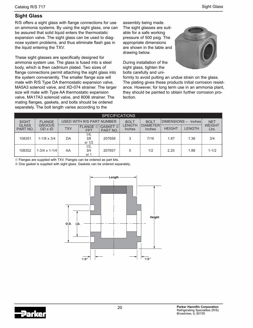
R/S offers a sight glass with flange connections for useon ammonia systems. By using the sight glass, one canbe assured that solid liquid enters the thermostaticexpansion valve. The sight glass can be used to diag-nose system problems, and thus eliminate flash gas inthe liquid entering the TXV.
These sight glasses are specifically designed forammonia system use. The glass is fused into a steelbody, which is then cadmium plated. Two sizes offlange connections permit attaching the sight glass intothe system conveniently. The smaller flange size willmate with R/S Type DA thermostatic expansion valve,MA5A3 solenoid valve, and XD-074 strainer. The largersize will mate with Type AA thermostatic expansionvalve, MA17A3 solenoid valve, and 8006 strainer. Themating flanges, gaskets, and bolts should be orderedseparately. The bolt length varies according to the
assembly being made.The sight glasses are suit-able for a safe workingpressure of 500 psig. Theappropriate dimensionsare shown in the table anddrawing below.
During installation of thesight glass, tighten thebolts carefully and uni-formly to avoid putting an undue strain on the glass.The plating gives these products initial corrosion resist-ance. However, for long term use in an ammonia plant,they should be painted to obtain further corrosion pro-tection.
Sight Glass
SNOITACIFICEPS
THGISSSALG
TRAP .ON
EGNALFEVOORG
DIxDO
REBMUNTRAPS/RHTIWDESU TLOBHTGNEL
sehcnI
TLOBRETEMAID
sehcnI
sehcnI–SNOISNEMID TENTHGIEW
.sbLVXT EGNALF ➀TPF
TEKSAG ➁.ONTRAP THGIEH HTGNEL
153801 4/3x8/1-1 AD,4/1
8/32/1ro
856702 3 61/7 78.1 63.1 4/3
253801 4/1-1x4/3-1 AA,2/1
4/31ro
756702 5 2/1 52.2 88.1 2/1-1
1/8”
Height
1/8”
Length
O.D. I.D.
➀ Flanges are supplied with TXV. Flanges can be ordered as part kits.➁ One gasket is supplied with sight glass. Gaskets can be ordered separately.
Sight Glass
Parker Hannifin CorporationRefrigerating Specialties (R/S) Broadview, IL 60155
Catalog R/S 717
21
General Information
General Information
WarrantiesAll Refrigerating Specialties products are warrantedagainst defect in workmanship and materials for a peri-odof one year from date of shipment from originatingfactory. This warranty is in force only when products areproperly installed, field assembled, maintained andoperated in use and service, as specifically stated inRefrigerating Specialties Catalogs or Bulletins for nor-mal refrigeration applications, unless otherwiseapproved in writing by Refrigerating Specialties Division.Defective products, or parts thereof, returned to the fac-tory with transportation charges prepaid, and found to bedefective by factory inspection, will be replaced orrepaired at Refrigerating Specialties option, free ofcharge, F.O.B. factory. Warranty does not cover prod-ucts which have been altered, repaired in the field, dam-aged in transit or have suffered accidents, misuse orabuse. Products disabled by dirt or other foreign sub-stances will not be considered defective. THEEXPRESS WARRANTY SET FORTH ABOVE CONSTI-TUTES THE ONLY WARRANTY APPLICABLE TOREFRIGERATING SPECIALTIES PRODUCTS, AND ISIN LIEU OF ALL OTHER WARRANTIES, EXPRESSEDOR IMPLIED, WRITTEN OR ORAL, INCLUDING ANYWARRANTY OF MERCHANTABILITY OR FITNESSFOR A PARTICULAR PURPOSE AND IN NO EVENT ISREFRIGERATING SPECIALTIES RESPONSIBLE FORANY CONSEQUENTIAL DAMAGES OF ANY NATUREWHATSOEVER. No employee, agent, dealer or otherperson is authorized to give any warranties on behalf ofRefrigerating Specialties, nor to assume, forRefrigerating Specialties, any other liability in connectionwith any of its products.
For More InformationConsult our web site www.parker.com/rs for the mostcurrent bulletins and catalog information on all our prod-ucts.
Safe OperationPeople doing any work on a refrigeration system mustbe qualified and completely familiar with the systemand the Refrigerating Specialties Division valvesinvolved, or all other precautions will be meaningless.This includes reading and understanding pertinentRefrigerating Specialties Division product bulletinsand Bulletin RSB prior to installation or servicingwork. Where cold refrigerant liquid lines are used, it isnecessary that certain precautions by taken to avoiddamage which could result from liquid expansion.Temperature increase in a piping section full of solidliquid will cause high pressure due to theexpanding liquid which can possibly rupture a gasket,pipe or valve. All hand valves isolating such sectionsshould be marked, warning against accidental clos-ing, and must not be closed until the liquid isremoved. (Tags are available for this purpose fromthe factory.) Check valves must never be installedupstream of solenoid valves or regulators with electricshut-off, nor should hand valves upstream of solenoidvalves or downstream of check valves be closed untilthe liquid has been removed. It is advisable to prop-erly install relief devices in any section where liquidexpansion could take place. Avoid all piping or controlarrangements which might produce thermal or pres-sure shock. For the protection of people and prod-ucts, all refrigerant must be removed from the sectionto be worked on before a valve strainer or otherdevice is opened or removed. Flanges with ODS con-nections are not suitable for ammonia service.
General InformationFactory Repair and Rebuilding For the convenienceof our customers, we have a standard factory repairand rebuilding service. Repairable returned regula-tors are disassembled, cleaned, sandblasted, wornparts replaced, reassembled and repainted. Forquickest service, it is advisable that this be done dur-ing the off peak season.
Parker Hannifin CorporationRefrigerating Specialties (R/S) Broadview, IL 60155
Catalog R/S 717
22
The items described in this document and other documents or descriptions provided by Parker Hannifin Corporation, its subsidiaries and its authorizeddistributors are hereby offered for sale at prices to be established by Parker Hannifin Corporation, its subsidiaries and its authorized distributors. Thisoffer and its acceptance by any customer ("Buyer") shall be governed by all of the following Terms and Conditions. Buyerís order for any such items,when communicated to Parker Hannifin Corporation, its subsidiary or an authorized distributor ("Seller") verbally or in writing, shall constitute acceptanceof this offer.
Offer of Sale
1. Terms and Conditions of Sale: All descriptions, quotations, pro-posals, offers, acknowledgments, acceptances and sales of Seller’sproucts are subject to and shall be governed exclusively by the termsand conditions stated herein. Buyer’s acceptance of any offer to sell islimited to these terms and conditions. Any terms or conditions in addi-tion to, or inconsistent with those stated herein, proposed by Buyer inany acceptance of an offer by Seller, are hereby objected to. No suchadditional, different or inconsistent terms and conditions shall becomepart of the contract between Buyer and Seller unless expressly accept-ed in writing by Seller. Seller’s acceptance of any offer to purchase byBuyer is expressly conditional upon Buyer’s assent to all the terms andconditions stated herein, including any terms in addition to, or incon-sistent with those contained in Buyerís offer, Acceptance of Sellerísproducts shall in all events constitute such assent.2. Payment: Payment shall be made by Buyer net 30 days from thedate of delivery of the items purchased hereunder. Amounts not timelypaid shall bear interest at the maximum rate permitted by law for eachmonth or portion thereof that the Buyer is late in making payment. Anyclaims by Buyer for omissions or shortages in a shipment shall bewaived unless Seller receives notice thereof within 30 days afterBuyer’s receipt of the shipment.3. Delivery: Unless otherwise provided on the face hereof, deliveryshall be made F.O.B. Seller’s plant. Regardless of the method of deliv-ery, however, risk of loss shall pass to Buyer upon Sellerís delivery toa carrier. Any delivery dates shown are approximate only and Sellershall have no liability for any delays in delivery.4. Warranty: Seller warrants that the items sold hereunder shall befree from defects in material or workmanship for a period of 18 monthsfrom date of shipment from Parker Hannifin Corporation. THIS WAR-RANTY COMPRISES THE SOLE AND ENTIRE WARRANTY PER-TAINING TO ITEMS PROVIDED HEREUNDER. SELLER MAKES NOOTHER WARRANTY, GUARANTEE, OR REPRESENTATION OFANY KIND WHATSOEVER. ALL OTHER WARRANTIES, INCLUDINGBUT NOT LIMITED TO, MERCHANTABILITY AND FITNESS FORPURPOSE, WHETHER EXPRESS, IMPLIED, OR ARISING BYOPERATION OF LAW, TRADE USAGE, OR COURSE OF DEALINGARE HEREBY DISCLAIMED. NOTWITHSTANDING THE FOREGO-ING, THERE ARE NO WARRANTIES WHATSOEVER ON ITEMSBUILT OR ACQUIRED WHOLLY OR PARTIALLY, TO BUYER’SDESIGNS OR SPECIFICATIONS.5. Limitation Of Remedy: SELLER’S LIABILITY ARISING FROM ORIN ANY WAY CONNECTED WITH THE ITEMS SOLD OR THIS CON-TRACT SHALL BE LIMITED EXCLUSIVELY TO REPAIR ORREPLACEMENT OF THE ITEMS SOLD OR REFUND OF THE PUR-CHASE PRICE PAID BY BUYER, AT SELLER’S SOLE OPTION. INNO EVENT SHALL SELLER BE LIABLE FOR ANY INCIDENTAL,CONSEQUENTIAL OR SPECIAL DAMAGES OF ANY KIND ORNATURE WHATSOEVER, INC. INCLUDING BUT NOT LIMITED TOLOST PROFITS ARISING FROM OR IN ANY WAY CONNECTEDWITH THIS AGREEMENT OR ITEMS SOLD HEREUNDER,WHETHER ALLEGED TO ARISE FROM BREACH OF CONTRACT,EXPRESS OR IMPLIED WARRANTY, OR IN TORT, INCLUDINGWITHOUT LIMITATION, NEGLIGENCE, FAILURE TO WARN ORSTRICT LIABILITY.6. Changes, Reschedules and Cancellations: Buyer may request tomodify the designs or specifications for the items sold hereunder aswell as the quantities and delivery dates thereof, or may request tocancel all or part of this order, however, no such requested modifica-tion or cancellation shall become part of the contract between Buyerand Seller unless accepted by Seller in a written amendment to thisAgreement. Acceptance of any such requested modification or cancel-lation shall be at Seller’s discretion, and shall be upon such terms andconditions as Seller may require.7. Special Tooling: A tooling charge may be imposed for any special-tooling, including without limitation, dies, fixtures, molds and patterns,acquired to manufacture items sold pursuant to this contract. Suchspecial tooling shall be and remain Seller’s property notwithstandingpayment of any charges by Buyer. In no event will Buyer acquire anyinterest in apparatus belonging to Seller which is utilized in the notwith-standing any charges paid by Buyer. Unless otherwise agreed, Sellershall have the right to alter, discard or otherwise dispose of any specialtooling or other property in its sole discretion at any time.
8. Buyer’s Property: Any designs, tools, patterns, materials, drawings, confi-dential information or equipment furnished by Buyer or any other items whichbecome Buyer’s property, may be considered obsolete and may be destroyedby Seller after two (2) consecutive years have elapsed without Buyer placing anorder for the items which are manufactured using such property, Seller shall notbe responsible for any loss or damage to such property while it is in Seller’s pos-session or control.9. Taxes: Unless otherwise indicated on the face hereof, all prices and chargesare exclusive of excise, sales, use, property, occupational or like taxes whichmay be imposed by any taxing authority upon the manufacture,sale or delivery of the items sold hereunder. If any such taxes must be paidby Seller or if Seller is liable for the collection of such tax, the amount thereofshall be in addition to the amounts for the items sold. Buyer agrees to payall such taxes or to reimburse Seller therefore upon receipt of its invoice. IfBuyer claims exemption from any sales, use or other tax imposed by any taxingauthority, Buyer shall save Seller harmless from and against any such tax,together with any interest or penalties thereon which may be assessed if theitems are held to be taxable.10. Indemnity For Infringement of Intellectual Property Rights: Sellershall have no liability for infringement of any patents, trademarks, copyrights,trade dress, trade secrets or similar rights except as provided in thisPart 10. Seller will defend and indemnify Buyer against allegations of infringe-ment of U.S. Patents, U.S. Trademarks, copyrights, trade dress and tradesecrets (hereinafter ëIntellectual Property Rightsí). Seller will defend at itsexpense and will pay the cost of any settlement or damages awarded in anaction brought against Buyer based on an allegation that an item sold pursuantto this contract infringes the Intellectual Property Rights of a third party. Sellerísobligation to defend and indemnify Buyer is contingent on Buyer notifying Sellerwithin ten (10) days after Buyer becomes aware of such allegations of infringe-ment, and Seller having sole control over the defense of any allegations oractions including all negotiations for settlement or compromise. If an item soldhereunder is subject to a claim that it infringes the Intellectual Property Rights ofa third party, Seller may, at its sole expense and option, procure for Buyer theright to continue using said item, replace or modify said item so as to make itnoninfringing, or offer to accept return of said item and return the purchase priceless a reasonable allowance for depreciation. Notwithstanding the foregoing,Seller shall have no liability for claims of infringement based on information pro-vided by Buyer, or directed to items delivered hereunder for which the designsare specified in whole or part by Buyer, or infringements resulting from the mod-ification, combination or use in a system of any item sold hereunder. The fore-going provisions of this Part 10 shall constitute Sellerís sole and exclusiveliability and Buyer’s sole and exclusive remedy for infringement of IntellectualProperty Rights. If a claim is based on information provided by Buyer or if thedesign for an item delivered hereunder is specified in whole or in part by Buyer,Buyer shall defend and indemnify Seller for all costs, expenses or judgmentsresulting from any claim that such item infringes any patent, trademark, copy-right, trade dress, trade secret or any similar right.11. Force Majeure: Seller does not assume the risk of and shall not be liable fordelay or failure to perform any of Seller’s obligations by reason of circumstancesbeyond the reasonable control of Seller (hereinafter Events of Force Majeure’).Events of Force Majeure shall include without limitation, accidents, acts of God,strikes or labor disputes, acts, laws, rules or regulations of any government orgovernment agency, fires, floods, delays or failures in delivery of carriers or sup-pliers, shortages of materials and any other cause beyond Sellerís control.12. Entire Agreement/Governing Law: The terms and conditions set forthherein, together with any amendments, modifications and any different terms orconditions expressly accepted by Seller in writing, shall constitute the entireAgreement concerning the items sold, and there are no oral or other represen-tations or agreements which pertain thereto. This Agreement shall be governedin all respects by the law of the State of Ohio. No actions arising out of the saleof the items sold hereunder or this Agreement may be brought by either partymore than two (2) years after the cause of action accrues.
General Information
Parker Hannifin CorporationRefrigerating Specialties (R/S) Broadview, IL 60155
Catalog R/S 717
23
General Information
Copyright 2005, Parker Hannifin Corporation, All Rights Reserved. The items described in this document are hereby offered for sale by Parker HannifinCorporation, its subsidiaries or its authorized distributors. This offer and its acceptance are governed by the provisions stated in the Offer of Sale.

R/S 7173/05
Parker Hannifin CorporationRefrigerating Specialties (R/S) Division2445 South 25th AvenueBroadview, IL 60155-3891Phone: (708) 681-6300 or 1-800-506-4261Fax: (708) 681-6306 or [email protected]/rs