refrigerant emissions in australia · refrigerant emissions in australia . expert group | 3 ......
TRANSCRIPT

EXPERT GROUP | 1
GROUP
Sources, causes and remedies, 2010
Refrigerant emissions in Australia
EXPERT GROUP | 3
Executive Summary Introduction
Background and scope Research methodology Description of technology, key components and definitions
Section 1: Sources and causes of direct emissions
1.1 Definition of refrigerant leaks 1.2 Definition of sources and causes of leaks 1.3 Industry survey results
Section 2: Losses from retrofitting of systems
Section 3: Existing Regulations, Codes of Practice, Standards and technical specifications
3.1 Australia 3.2 United Kingdom 3.3 European Union 3.4 North America
Section 4: Options to reduce leaks and potential benefits
4.1 Regulatory, technical and commercial mechanisms 4.2 Containment and trigger rate measures 4.3 Technical Standards and Codes of Practice 4.4 Skills, training and best practice 4.5 Commercial drivers including financial incentives, CPRS or taxes 4.6 Potential direct and indirect emission benefits
Recommendations
References
Acknowledgments
Appendices
Appendix I: Copy of survey questionnaire Appendix II: Industry survey, suggestions and comments
List of Figures
Figure 1: Typical SMCR vapor compression system
Figure 2: Pareto chart of top sources of refrigerant leaks
Figure 3: Pareto chart of top causes of refrigerant leaks
Figure 4: Return bends and end plate of refrigeration coil
Figure 5: Leaking condenser in the field
Figure 6: Refrigerant leaking from a filter with flared connections
Figure 7: Range of Schrader valves
Figure 8: Uncapped Schrader valve fitted to refrigeration coil header
Figure 9: Common packed capped service valve with brass cap
Figure 10: Typical pressure switches offered in a variety of connection types
Figure 11: Shaft seal assembly on an open drive compressor
Figure 12: Range of current and potential regulatory, technical and commercial measures
Figure 13: Flare/solder adaptors to replace flared connections
Figure 14: Micro-channel refrigeration coil
List of Tables
Table 1: Summary of Code of Practice requirements in Australia
Table 2: Comparison of the legal frameworks of Europe, Germany and Austria
Table 3: Leak repair trigger rates under Section 608 of the Clean Air Act
Table 4: Summary of technical feedback from qualitative interviews
Table 5: Direct emissions from refrigerant leaks for a range of leak rate scenarios
Table 6: Electricity consumption and indirect emissions for SMCR by sector and equipment type
Table 7: The primary sources and causes of refrigerant leaks in SMCR
CONTENTS
This paper has been prepared for the Australian Government, Department of the Environment, Water, Heritage and the Arts, Environment Protection Branch.
Prepared by Expert Group (A.C.N. 122 581 159) Authors: Peter Brodribb and Michael McCann Ph: 61 3 9592 9111 Fx: 61 3 9592 1846 Email: [email protected] Web address: www.expertgroup.com.au
Disclaimer:
Some information contained within this report, and used for the underlying analysis may be considered to be of a sensitive nature. The Expert Group has made its best endeavours to ensure the accuracy and reliability of the data used herein, however makes no warranties as to the accuracy of the data herein nor accepts any liability for any action taken or decision made based on the contents of this report.
For bibliographic purposes this report may be cited as: Refrigerant emissions in Australia: Sources, causes and remedies, prepared by the Expert Group for the Department of the Environment, Water, Heritage and the Arts, 2010.
© Commonwealth of Australia (2009) ISBN: Pending
This work is copyright protected. Apart from any use as permitted under the Copyright Act 1968, no part may be reproduced by any process without prior written permission from the Australian Government, available from the Department of the Environment, Water, Heritage and the Arts. Requests and inquiries concerning reproduction and rights should be addressed to:
The Communication Director Department of the Environment, Water, Heritage and the Arts GPO Box 787, Canberra ACT 2601
For further information please contact: Ozone and Synthetic Gas Team Environment Protection Branch Department of the Environment, Water Heritage and the Arts GPO Box 787 Canberra ACT 2601 Website: www.environment.gov.au/atmosphere/

4 | EXPERT GROUP EXPERT GROUP | 5
This study has investigated the causes and sources of leaks of refrigerant gases using interviews with active field service personnel combined with an existing intimate knowledge of available systems and technologies. There is a high degree of similarity between the sources and causes of leaks identified by the professionals in Australia interviewed for this study, and those identified by the UK Institute of Refrigeration published in January 2009 (IOR, 2009).
This report concludes that:
• Leaks result from a limited number of known and identifiable failures in equipment and field practices.
• There are many technical and field work practices available that will deliver an overall and ongoing reduction in losses of refrigerant gas from equipment.
• The greatest barrier to changes in behavior and leak reduction is market failure, i.e., almost all options to reduce leaks incur time and resource costs that are more expensive to the field operator, the service company and the equipment owner, than the option often chosen of ‘living with leaks’ and simply topping up refrigerant gas.
The reality of market failure flows from the inescapable fact that the cost of refrigerant gas, versus the cost of labor, parts, and the effort required to minimize leaks, means that there is no significant economic incentive to reduce leaks.
While there is regulation in place that prohibits emissions to atmosphere of refrigerant gas when being handled, or when machines are being serviced and recharged, thereis no regulation that prohibits the operation of a machine by its owner while it has preventable and measureable leaks of refrigerant gas. It is also fair to question if sucha regulation could be enforced, and thus whether such a regulation would result in any practical benefit.
Numerous potential changes to system components and work practices that would immediately reduce leaks are not technically challenging, however training regimes, and indeed the training opportunities across the entire workforce, need review and expansion.
A summary of the ‘dirty dozen’ sources and causes of refrigerant leaks are provided in the recommendations to emphasize the technical, regulatory and commercial measures that are needed as remedies to deliver practical, sustainable outcomes.
Regulation and taxes either in force or being contemplated in several European countries, including Denmark, Norway, Sweden and France, and in California, demonstrate various approaches to changing the economic relationships that presently make preventable leaks in Australia uneconomic to avoid in many cases.
Quantification of the benefits of proposed changes has proved difficult given the very limited hard data on the quantum of leaks from any particular cause. However, based on best available data, and the results of industry surveys and consultation, an effort has been made to conservatively estimate the emissions that could be avoided through practical leak reduction strategies.
Given the inherent uncertainties in this exercise and noting the qualifications of having little hard data, the authors estimate that annual losses to air of refrigerant gas from the classes of equipment that are the subject of this study are equivalent to 798 kt CO2-e per annum.It is expected that at least one third of these losses, or 266 kt CO2-e in direct emissions and 64 to 128 ktCO2-e in indirect emissions from improved energy efficiency, could be avoided through the general application of the changes recommended herein.
EXECUTIVE SUMMARY
REFRIGERANT EMISSIONS IN AUSTRALIA: SOURCES, CAUSES AND REMEDIES

6 | EXPERT GROUP EXPERT GROUP | 7
The principal questions that need to be answered by the research are as follows:
QI. What are the sources and the causes of refrigerant leaks in the equipment types specified?
Q2. Where HCFC or HFC systems are retrofitted to run on an alternative HFC or natural refrigerant, do equipment components and/or the retrofitting procedure contribute to refrigerant being lost to the atmosphere? And if so, how?
Q3. Where HCFC systems are converted to use ‘drop in’ refrigerant replacements, do equipment components and/or the conversion procedure contribute to refrigerant being lost to the atmosphere? And if so, how?
Q4. What existing codes of practice, or international or Australian standards apply to the primary areas of concern, as identified in response to questions 1 to 3?
Q5. What additional technical specifications or standards (including compulsory adherence to existing non-compulsory codes of practice, international or Australia standards identified in response to question 4) could be imposed to reduce leaks?
Q6. If the additional technical specifications or standards identified in response to question 5 were introduced, what benefits would accrue in terms of (a) a reduction in refrigerant emissions, and (b) increases in energy consumption efficiency?
These questions have been answered in the main body of the report, with question 1 covered in Section 1: Sources and causes of direct emissions; questions 2 and 3 covered in Section 2: Losses from retrofitting systems; question 4 covered in Section 3: Existing Regulations, Codes of Practice, Standards and technical specifications, and questions 5 and 6 covered in Section 4: Options to reduce leaks and potential benefits.
Background and scopeThe Australian Government Department of the Environment, Water, Heritage and the Arts (DEWHA) is considering the need for new equipment standards for the purpose of minimising leaks of refrigerant gas from commercial refrigeration equipment. Some classes of commercial refrigeration equipment are known to have high leak rates.
DEWHA wants to establish a greater understanding of the sources and the causes of leaks, options for technical standards that could reduce leaks, and the quantitative benefits of such standards in terms of reducing leaks, and any consequential impacts on energy consumption efficiency.
Small and medium refrigeration equipment used in cool rooms, clubs, pubs, hotels and liquor retailing, the catering, hospitality and retail food sectors were identified as having high leak rates. Installations of these classes of equipment can lose in the order of 10% to 30% of refrigerant charge per annum via leaks. Addressing the occurrence of leaks in these types of equipment could make significant reductions in refrigerant gas emissions to atmosphere.
The study excludes the following equipment:
• Fully self contained commercial systems as they are typically hermetically sealed with low leak rates;1
• Refrigeration systems that are not HCFC or HFC based (primarily ammonia or carbon dioxide charged systems);
• Transport and marine refrigeration; Milk vat refrigeration;
• Automotive air conditioning;
• Ice cream bins and soft drink machines and similar equipment maintained under product supplier contracts;
• Large and very large commercial refrigeration, (these systems are generally owned and maintained by large retail or distribution chains for whom effective refrigeration systems are core to their business and who have full-time engineering staff charged with maintenance programs);
• Large commercial air conditioning systems, and Domestic systems.
While on the surface this list of exclusions may appear to remove a significant proportion of the stock of equipment from the scope of the study, the reality is that this still leaves a very large stock of equipment as the subject of this study, and classes of equipment that are well known for experiencing very high leak rates such as walk-in cool rooms and freezers, refrigerated display cabinets, and beer chilling equipment with remote condensing units.
At the same time some of the practices and technology identified here that would contribute to lower losses from the subject equipment, will also apply in some cases to classes of equipment excluded in the list above.
INTRODUCTION
1 A hermetically sealed system is a system in which all refrigerant containing parts are made tight by welding, brazing or a similar permanent connection which may include capped valves and capped service ports that allow proper repair or disposal and which have a tested leakage rate of less than 3 grams per year under a pressure of at least a quarter of the maximum allowable pressure (F-Gas 842/2006).

8 | EXPERT GROUP EXPERT GROUP | 9
HP/LPPRESSURESWITCH
VAPORVAPOR
COMPRESSOR
EVAPORATOR
TX VALVESOLANOIDVALVE
FILTERDRIER
SIGHTGLASS
LIQUID + VAPOR
FANWARMAIR
COLDAIR
AIR ORWATERCOOLEDCONDENSER
LIQUID RECEIVER
LIQUID LINE
The vapor compression refrigeration system uses a circulating refrigerant as the medium that absorbs and removes heat from the space to be cooled (i.e. walk-in coolroom) via the evaporator and subsequently rejects that heat via the condenser. The large majority of refrigerant used in SMCR is a synthetic refrigerant known as Hydrofluorocarbons (HFCs), which is referred to as F-Gas in European Regulations and Synthetic greenhouse gases (SGGs) in Australia, and are covered under the Kyoto Protocol. A second family of refrigerant gas, Hydrochlorofluorocarbons (HCFCs), described as Ozone Depleting Substances (ODS) under the Montreal Protocol are being phased out, although are still in widespread use at this time. The term fluorocarbon refrigerant is used to describe both HFCs and HCFCs.
Natural refrigerants2 are rarely found in SMCR applications in Australia but are found in other refrigeration applications outside the scope of this assignment such as:
• Hydrocarbons in domestic refrigerators or small self-contained retail display cabinets (QGDME, 2009);
• Carbon Dioxide (R7443) in supermarkets rack systems (R744 cascade systems with HFCs or R744 only direct expansion systems); and
• Anhydrous ammonia (R717) in large process refrigeration or cold storage applications where it is commercially viable above refrigeration capacities of approximately 100 kWr for low temperature applications, and above 300 kWr for medium temperature applications.
Total emissions from refrigeration equipment as defined by this assignment are the sum of the direct emissions due to refrigerant leaks, and indirect emissions of greenhouse gases resulting from electricity use, and are expressed in kg or tonnes of CO2 equivalent (CO2-e). Other emissions from refrigeration equipment includes direct emissions from manufacturing leakage (refrigerant and equipment) and end-of-equipment life, and indirect emissions from energy consumption during chemical production, transport, manufacturing components/assembly and end-of-life.
Research MethodologyThe study commenced in November 2009 with three concurrent activities involving a combination of industry based consultation, surveys and desktop research.
The key industry personnel with the knowledge to answer questions 1 to 3 are the engineers involved in the design, manufacture, specification, installation and warranties of refrigeration equipment, and the refrigeration technicians installing, servicing and repairing the equipment. RACCA (Refrigeration and Air Conditioning Contractors Association) and AREMA (Air-conditioning and Refrigeration Equipment Manufacturers Association of Australia) are the key industry bodies representing these key technical personnel.
A quantitative survey of RACCA members was undertaken which targeted refrigeration technicians and contracting businesses installing, servicing and repairing refrigeration equipment. Participants were able to nominate and comment on the major sources and causes of leaks they have encountered or repaired over the past 12 to 24 months. A copy of the questionnaire is provided in Appendix I and the survey results provided statistically significant data from 156 respondents (45% NSW, 23% Vic, 13% Qld, 11% SA and 8% SA) are discussed in Section 1: Sources and causes of direct emissions.
In parallel with this quantitative analysis, qualitative discussions were undertaken with key industry experts who are members of AREMA or who are otherwise associated with the refrigerant distribution chain. The purpose of these discussions was to capture technical information, explore technical intricacies and provide an opportunity for industry to comment or make suggestions. The participants in these discussions were primarily engineers, equipment manufacturers or industry leaders with specialist technical expertise and industry knowledge. A list of participants is provided in the Acknowledgments and many of the technical comments and suggestions are provided and discussed in Section 4.3 Technical Standards and Codes of Practice.
The third pillar of the study was desktop research into existing international and Australian Codes of Practice, Regulations and technical Standards that apply to the primary areas of concern, as identified in response to questions 1 to 3. Previous research undertaken by Peter Brodribb and Michael McCann that resulted in preparation of Australia’s first national inventory of synthetic greenhouse gases, and an estimate of the refrigerant bank, leak rates and national direct/indirect emissions was used as a baseline to calculate and quantify potential benefits of proposed policy options (ES, 2007a, ES, 2007b and ES, 2008).
Description of technology, key components and definitionsThe technology that is the focus of the study can be characterized as:
• small to medium commercial refrigerating (SMCR) systems;
• with remote condensers;
• with an application temperature range below 7oC;
• using the vapor compression cycle;
• with reciprocating (hermetic or semi-hermetic or open drive), scroll and some rotary compressors, and
• driven by electric motors.
Figure 1 depicts a typical, single-stage vapor-compression system. All such systems have four main components:
1. Compressor;
2. Condenser, typically air cooled with fan(s) and motor(s) or can be water cooled;
3. Thermostatic expansion valve abbreviated by industry to TX valve (also called a throttle valve), and an
4. Evaporator with fan(s) and motor(s).
Other common components found on SMCR include:
5. Dual (high and low) pressure controls (screw, flare or solder connections) with copper capillary, nylon flexible, steel breaded or !” copper lines;
6. Service valves typically brass ‘packed capped’ valves with packing glands and brass or plastic valve caps and service access ports available in flare or solder connections;
7. Service access points typically Schrader valve connections;
8. Liquid receiver typically with screwed and solder connections;
9. Filter drier;
10. Solenoid valve, and
11. Sight glass.
Each of these components and their connections has potential to cause refrigerant leaks. The level of risk of them causing leaks depends on the size and complexity of the refrigeration system, types of connections and service points, operating conditions (i.e. pressures, ambient temperatures, vibration), equipment design and vintage, quality of maintenance, and many other factors. TX valves, filter driers, solenoid valves and sight glasses are installed with either flare or solder connections.
2 The term ‘natural’ implies the origin of the fluids as they occur in nature as a result of geological and/or biological processes, unlike fluorinated refrigerants that are synthesized chemicals. However it has to be noted that all ‘natural’ refrigerants are refined and compressed by bulk gas manufacturers via some process and transported like other commercial gases so also have an ‘energy investment’ in their creation, storage and transport.
3 Refers to the ASHRAE refrigerant number for synthetic and natural refrigerants, where R744 is carbon dioxide, R717 is anhydrous ammonia and R290 is propane.
Figure 1: Typical SMCR vapor compression system
10 | EXPERT GROUP EXPERT GROUP | 11
SOURCES AND CAUSES OF DIRECT EMISSIONS
Q1. What are the sources and causes of refrigerant leaks in the equipment types specified?
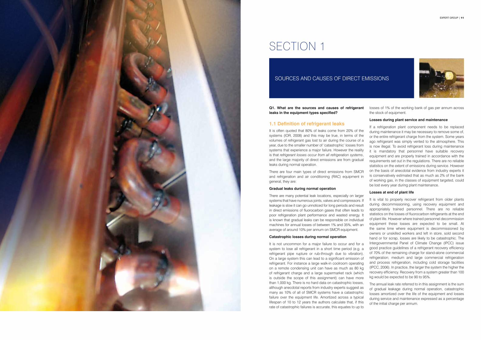
1.1 Definition of refrigerant leaksIt is often quoted that 80% of leaks come from 20% of the systems (IOR, 2008) and this may be true, in terms of the volumes of refrigerant gas lost to air during the course of a year, due to the smaller number of ‘catastrophic’ losses from systems that experience a major failure. However the reality is that refrigerant losses occur from all refrigeration systems, and the large majority of direct emissions are from gradual leaks during normal operation.
There are four main types of direct emissions from SMCR and refrigeration and air conditioning (RAC) equipment in general, they are:
Gradual leaks during normal operation
There are many potential leak locations, especially on larger systems that have numerous joints, valves and compressors. If leakage is slow it can go unnoticed for long periods and result in direct emissions of fluorocarbon gases that often leads to poor refrigeration plant performance and wasted energy. It is known that gradual leaks can be responsible on individual machines for annual losses of between 1% and 35%, with an average of around 10% per annum on SMCR equipment.
Catastrophic losses during normal operation
It is not uncommon for a major failure to occur and for a system to lose all refrigerant in a short time period (e.g. a refrigerant pipe rupture or rub-through due to vibration). On a large system this can lead to a significant emission of refrigerant. For instance a large walk-in coolroom operating on a remote condensing unit can have as much as 80 kg of refrigerant charge and a large supermarket rack (which is outside the scope of this assignment) can have more than 1,000 kg. There is no hard data on catastrophic losses, although anecdotal reports from industry experts suggest as many as 10% of all of SMCR systems have a catastrophic failure over the equipment life. Amortized across a typical lifespan of 10 to 12 years the authors calculate that, if this rate of catastrophic failures is accurate, this equates to up to
losses of 1% of the working bank of gas per annum across the stock of equipment.
Losses during plant service and maintenance
If a refrigeration plant component needs to be replaced during maintenance it may be necessary to remove some of, or the entire refrigerant charge from the system. Some years ago refrigerant was simply vented to the atmosphere. This is now illegal. To avoid refrigerant loss during maintenance it is mandatory that personnel have suitable recovery equipment and are properly trained in accordance with the requirements set out in the regulations. There are no reliable statistics on the extent of emissions during service. However on the basis of anecdotal evidence from industry experts it is conservatively estimated that as much as 2% of the bank of working gas, in the classes of equipment targeted, could be lost every year during plant maintenance.
Losses at end of plant life
It is vital to properly recover refrigerant from older plants during decommissioning, using recovery equipment and appropriately trained personnel. There are no reliable statistics on the losses of fluorocarbon refrigerants at the end of plant life. However where trained personnel decommission equipment these losses are expected to be small. At the same time where equipment is decommissioned by owners or unskilled workers and left in store, sold second hand or for scrap, losses are likely to be catastrophic. The Intergovernmental Panel of Climate Change (IPCC) issue good practice guidelines of a refrigerant recovery efficiency of 70% of the remaining charge for stand-alone commercial refrigeration; medium and large commercial refrigeration and process refrigeration, including cold storage facilities (IPCC, 2006). In practice, the larger the system the higher the recovery efficiency. Recovery from a system greater than 100 kg would be expected to be 90 to 95%.
The annual leak rate referred to in this assignment is the sum of gradual leakage during normal operation, catastrophic losses amortized over the life of the equipment and losses during service and maintenance expressed as a percentage of the initial charge per annum.
SECTION 1

12 | EXPERT GROUP EXPERT GROUP | 13
1.3 Industry survey resultsA quantitative survey of RACCA members was undertaken which targeted refrigeration technicians and contracting businesses installing, servicing and repairing refrigeration equipment. Participants were able to nominate and comment on the major sources and causes of leaks they have encountered or repaired over the past 12 to 24 months. A copy of the questionnaire is provided in Appendix I.
The sources of fluorocarbon refrigerant leaks were reported as a yes or no, which is summarized into a Pareto chart in Figure 2. The chart shows a high proportion of leaks are encountered with flared joints (88% of participants), return bends on evaporators or condensers (86% of participants) and Schrader valves (83% of participants).
To determine the top causes of leaks, participants were asked to number the most common causes of leaks from 1 to 10, either selecting from a list of 20 potential causes, or to nominate others. A survey result of 1 was given a score of 10 and scores were allocated to other numbers similarly (i.e. a survey result of 2 was given a score of 9, a survey result of 3 was given a score of 8 etc.). The scores for each cause are added together to give a final score that rates the observed causes of leaks. The results are summarized into a Pareto chart in Figure 3 scaled against a maximum score of 100.
There is a surprising degree of similarity between the sources and causes identified in this study and those identified by the UK Institute of Refrigeration published in January 2009 (IOR, 2009). This not only affirms the findings of the survey conducted for this study, but points to a number of common failures in material, technical measures and work practices.
The survey results found mechanical joints (i.e. includes flared joints), poor vibration elimination and a lack of regular service and maintenance as the ‘major causes’ of refrigerant leaks. The current market structure poses a significant barrier to preventative maintenance as a majority of SMCR equipment is owned, installed and maintained by small to medium enterprises (i.e. end users and contractors) who are all, by and large, driven by short term financial objectives. The survey result is a clear message that the industry requires regulatory support to improve service and maintenance practices in this populous but generally cash restrained market segment.
The IPCC uses the same definition where stand-alone commercial refrigeration applications with a charge ranging from 0.2 to 6 kg have an annual leak rate of 1% to 15% of initial charge per annum (IPCC, 2006). The lower end of the range of leak rates would mostly represent hermetically sealed self-contained refrigeration equipment, and the upper guideline would mostly represent equipment with remote condensing units such as SMCR.
The IPCC estimate is significantly lower than the 23% annual leak rate for commercial refrigeration prescribed by the Department of Climate Change National Greenhouse and Energy Reporting (NGERS) Technical Guidelines and the NGERS Act 2007. In this study we use an annual leak rate of 15% per annum for SMCR equipment. While this is at the upper end of the range used by the IPCC, based on extensive research and interviews with technicians for this study, and in the course of research undertaken in recent years for related projects, it was determined that 15% annual losses is a justifiable value for the purposes of this work.
1.2 Definition of sources and causesIn the design of this project and the construction of the survey a considerable amount of time was spent articulating lists of sources, and causes of leaks.
Sources of leaks can be broadly defined as components that result in leaks when they fail.
Causes of leaks can be thought of as system design and performance characteristics, or workplace practices that increase the likelihood of leaks – often through accelerating the degradation and eventual failure of components. Thus a cause of a leak can be for instance as a result of excess vibration because of insufficient vibration damping which ultimately causes a component failure.
At that point there is a cross over between sources and causes. Some components are more common sources of leaks than others. Some common causes of leaks result in rapid degradation of certain components. The co-incidence of the poorest performing components and the most common causes of their failure are explored in some detail in Section 1.3 and later addressed in recommendations for changes.
The survey results show the main sources of refrigerant leaks encountered are flared joints (88% of participants), return bends on evaporators or condensers (86% of participants) and Schrader valves (83% of participants).
SECTION 1

14 | EXPERT GROUP EXPERT GROUP | 15
In aggregate condensers and evaporators were major sources of leaks with 86% of participants recording leaks from return bends on condensers or evaporators, 54% of participants encountered failures with condensers and corrosion of condensers was in the top 10 key causes of leaks. Forty five percent (45%) of participants encountered failures with condensate tray pipe work, which is likely to be due to corrosion from food acids in the condensate tray and evaporator. The combination of this data suggests significant leaks are occurring on both evaporators and condensers and that the majority of these leaks could be avoided with improved equipment standards and more frequent and/or thorough maintenance practices. Figure 4 shows the end plate and return bends of a common refrigeration coil, and Figure 5 shows a refrigerant leak on an outdoor condensing unit.
Further field investigation to refine the understanding of the causes of leaks from evaporators and condensers would be useful. For example leaks on evaporators are likely to be caused by corrosion from food acids that can be minimized with protective coatings. Leaks on condensers often occur as a result of corrosion due to exposure to external elements such as salt in coastal applications, or where extreme temperature fluctuations cause the rapid expansion and contraction of the coil header and entry tubes. Floating head refrigeration coil designs were introduced over a decade ago to allow for expansion and contraction due to extreme temperature fluctuations. However if the end plate holes are too tight they rub on the copper tubes and can cause failures.
Participants were given the opportunity to comment or offer suggestions to minimize leaks, these suggestions have been provided in Appendix II: Industry survey, suggestions and comments. Inferior quality cheap imported equipment and the thin walled copper pipe were consistently sited as causes of refrigerant leaks, which are also likely to be causes of leaks from condensers and evaporators.
Flared joints and Schrader valves are widely acknowledged by industry as a key source of refrigerant leaks. Both the survey results and qualitative feedback from industry confirm this view. Flared joints and Schrader valves are used mostly for convenience, and there is scope to minimize these types of connections or, in the case of flares, eliminate them with flare/solder adaptors that are discussed in more detail in Table 4 and illustrated in Figure 13 in Section 4.3.
Mechanical joints (i.e. flares on driers) was found to be a major cause of refrigerant leaks, Figure 6 shows refrigerant leaking from a filter drier with flared connections. Figures 7 and 8 show a range of Schrader valves commonly supplied and an illustration of one installed on a refrigeration coil header.
Brazed joints were reported as a common source of leaks by 62% of respondents. The study did not clarify if the failures of brazed joints were due to factory or field soldered joints, however a lack of vibration elimination, poor brazing and insufficient pipe support all featured in the top 10 causes of refrigerant leaks. This suggests there are likely to be a combination of issues including the brazing skills of mechanics, the quality of the materials used (i.e. silver content of solder) and a lack of understanding of best practice techniques to eliminate vibration.
These items come under the broader heading of poor installation that was identified as the 4th highest cause of refrigerant leaks that generally occur as a result of a lack of skills and knowledge or commercial factors that lead to poor quality installations.
Service valves (i.e. shut off valves and ball valves) were reported as common sources of leaks by 49% of participants and uncapped valves was identified in the top 10 causes with packing glands and wear of spindles less significant causes. This finding was affirmed by the results of the study by the IOR which also found that most leaks occur due to uncapped valves (IOR, 2009). There are a variety of valves and cap types (i.e. brass, non removable and plastic) in use; Figure 9 shows a common service valve with a brass cap.
SECTION 1
100%90%80%70%60%50%40%30%20%10%
0%% s
urve
yed
rece
ntly
exp
erie
nced
or
repa
ired
leak
s
Flar
e jo
ints
88%
Ret
urn
bend
s on
eva
pora
tors
or c
onde
nser
s
86%
Schr
ader
val
ves
83%
Mec
hani
cal j
oint
s(fl
ange
s on
filte
r drie
rs)
65%
Ther
mos
tatic
Exp
ansi
on V
alve
63%
Bra
ised
join
ts
62%
Shaf
t sea
l(o
pen
type
com
pres
sor)
58%
Pres
sure
sw
itch
conn
ectio
ns
57%
Con
dens
er fa
ilure
54%
Shut
off
and
ball
valv
es
49%
Cop
per c
apai
llary
tube
s
45%
Con
dens
ate
tray
pip
ewor
k
45%
PVC
flex
ible
hose
line
s on
HP/
LP
40%
Leak
age
from
com
pres
sor b
ody
35%
O-r
ings
28%
Pres
sure
relie
f val
ves
and
fusi
ble
plug
s (o
ver p
ress
ure
prot
ectio
n)
19%
Pier
cing
and
line
tap
valv
es
18%
Fusi
ble
plug
s
12%
Oth
er S
ourc
es
3%
100%90%80%70%60%50%40%30%20%10%0%A
ggre
gate
cau
ses
scal
ed to
100
Mec
hani
cal j
oint
s(fl
ares
on
drie
rs)
Poor
vib
ratio
n el
imin
atio
n
Lack
of r
egul
ar s
ervi
cean
d m
aint
enan
ce
Poor
inst
alla
tion
Poor
bra
zing
Equi
pmen
t rep
lacm
ent
over
due
Insu
ffici
ent p
ipe
supp
ort
Unc
appe
d sc
hrad
er v
alve
s
Unc
appe
d va
lves
Cor
rosi
on o
f con
dens
ers
Insu
ffici
ent l
eak
test
ing
durin
g in
stal
latio
n
Pipe
cla
mps
that
cau
sew
ear a
nd ru
b th
roug
h
Wea
r of v
alve
pac
king
gla
nd
Poor
des
ign
(con
dens
ing
units
and
eva
pora
tors
)
Poor
acc
ess
mak
ing
serv
ice
diffi
cult
(con
ceal
ed p
ipew
ork)
Wea
r of v
alve
spi
ndle
Insu
ffici
ent l
eak
test
ing
durin
g se
rvic
e
Oth
er c
ause
s
Wro
ng p
ipe
thic
knes
s (d
esig
n)
Valv
e co
re d
amag
eddu
ring
braz
ing
Wro
ng p
ipe
thic
knes
s(in
stal
latio
n)
Use
of i
ncor
rect
refri
gera
nt
Figure 2: Sources of refrigerant leaks identified by refrigeration technicians and contracting businesses
Sources of refrigerant leaks
Key causes of leaks
4 Survey respondents were asked to number the most common causes of leaks from 1 to 10 from a list of 20 possible causes. Survey results were used to create a comparative score for each cause listed and the scores were then scaled against 100 in the chart above.
Figure 3: Observed causes of refrigerant leaks4

16 | EXPERT GROUP EXPERT GROUP | 17
The survey results confirm that effective maintenance is the key to reducing leaks on existing systems. Other approaches that flow logically from this field intelligence is avoiding the use of flared joints, placing caps on valves and the marking of joint locations on insulated piping.
Figure 4: End plate and return bends of a common refrigeration coil
Figure 8: Uncapped Schrader valve fitted to refrigeration coil header
Figure 6: Refrigerant leaking from a filter with flared connections
Figure 10: Typical pressure switches offered in a variety of connection types
Figure 5: Leaking condenser in the field5
Figure 9: In line valve complete with brass cap
Figure 7: Range of Schrader valves
Figure 11: Shaft seal assembly on an open drive compressor
SECTION 1 Figures 4 -11
Pressure switches are widely used on SMCR equipment to give protection against excessively low suction pressure or high discharge pressure, and are also used for starting and stopping refrigeration compressors and fans on air cooled condensers. The connections found on pressure switches in the field include copper capillary tube, !” copper lines (i.e. solder or flare) and flexible lines (i.e. PVC/nylon or stainless steel tubing covered with a protective stainless steel braid). Figure 10 shows a typical pressure switch and a variety of connection types. Other pressure control applications where connections can be found on SMCR include oil pressure controls on larger systems, variable condenser fan control or head pressure fan cycling.
The survey found that 45% of participants’ encountered refrigerant leaks from copper capillary tubes, 40% with PVC flexible lines and 57% from pressure switch connections. Nylon flexible hoses were introduced by industry around a decade ago as a longer lasting alternative to copper capillary tube, which is very susceptible to failure due to vibration. Nylon flexible hoses are generally connected with a !” flare at both ends which provides two potential leakage points and are the most common method of connecting pressure controls and switches as they are quick and easy to install. The type of connection that offers the highest degree of leak tightness and resistance to vibration when correctly installed is !” copper connections that are factory soldered at one end and field soldered at the other end.
Leaks from compressor bodies were reported by 35% of participants. The most common types of compressors in use on SMCR equipment are hermetic and semi-hermetic reciprocating compressors, and more recently Scroll compressors. Leaks from these types of compressors are virtually impossible and any leaks encountered are more likely to be from the valves (i.e. gaskets) connected to them. Old open drive compressors with shaft seals are commonly used in milk vat applications and on very old equipment and are notoriously leaky. This is the most likely explanation of this result. Shaft seals on open drive compressors were reported as a common source of leaks by 58% of respondents. Figure 11 shows a picture of a shaft seal assembly on an open drive compressor.
Piercing and line tap valves, o-rings (i.e. found in sight glasses and solenoid valves), pressure relief valves and fusible plugs were not found to be significant sources of refrigerant leaks. ‘Other sources’ not on the original questionnaire represented less than 3% of survey results and suggestions were mostly subsets of existing items (i.e. gaskets on service valves, leaking shaft seals, pressure switch bellows, flared outlets on TX valves and sight glass seal), which suggest the original questionnaire lists were comprehensive. Over 50% of ‘other causes’ nominated related to corrosion of evaporators with the majority of the remainder subsets of existing items (i.e. small pipes rubbing together, poor flaring, corrosion of compressors and poor workmanship).
The survey results confirm that effective maintenance is the key to reducing leaks on existing systems. Other approaches that flow logically from this field intelligence, such as avoiding use of flared joints, placing caps on valves and the marking of joint locations on insulated piping, are not difficult technically, but will require a number of fundamental changes at each stage of the process from procurement and specification, to design and installation, and finally in service and maintenance.
Based on the findings of the survey and comments from highly experienced industry practitioners, it is obvious that some changes to the fixtures, seals and fittings commonly used on RAC systems could cut leaks during normal operation and, to some extent, avoid catastrophic losses as well. The proposed changes are detailed in the list of technical measures outlined in Section 4.3, Technical Standards and Codes of Practice.
5 Source of Figures 5, 6, 8 and 11 from IOR 2009.

18 | EXPERT GROUP EXPERT GROUP | 19
LOSSES FROM RETROFITTING OF SYSTEMS
SECTION 2
Q2 and Q3. Where fluorocarbon systems are retrofitted to use a ‘drop in’ refrigerant replacement, an alternative HFC or natural refrigerant, do equipment components and/or the retrofitting procedure contribute to refrigerant being lost to the atmosphere? And if so, how?
The processes of retrofitting equipment to run on either HCFC ‘drop in’ replacement, an alternative HFC, or a natural refrigerant replacement are very similar for all gases with the same opportunities for losses to air. In the process of retrofitting any equipment, it must be degassed, which involves the recovery of the original refrigerant and the evacuation of the system. The act of degassing equipment is now a basic skill of all refrigeration technicians and the skills, the equipment, and the regulation requiring this are well established in Australia.
The two major global refrigerant suppliers Dupont and Arkema provide similar ‘drop in’ replacement guidelines and are summarized as follows:
1. Establish baseline performance with existing refrigerant.
2. Remove all old (R22 or other) refrigerant from the system into a recovery cylinder and weigh the amount removed.
3. Depending on the refrigerants, change oil in the system, which involves:
a) Drainage of the original oil from the system. An analysis of the original oil is recommended to ensure that the equipment is in a good state of repair; and
b) Fill with POE or other lubricant, in most cases no rinsing process is required and only 1 oil drainage is required.
4. Replace the filter drier and any critical elastomeric seals/gaskets.
5. Evacuate system and check for leaks.
6. Charge with suitable ‘drop in’ replacement refrigerant. Products currently available in Australia include Arkema R427A or Dupont R422A, R422D and R417A otherwise known as the ISEON product range or Technochem SP22C. The initial charge amount should be approximately 85% to 95% (depending on the volumetric differences of refrigerants) of the standard charge of the old refrigerant (R22 or other).
7. Start up system, adjust TX valve and/or charge size to achieve optimum superheat.
8. Monitor oil levels in compressor and add oil as required to maintain proper levels.
9. Label system showing the refrigerant (and any replacement lubricant) used. Update system logbook.

20 | EXPERT GROUP EXPERT GROUP | 21
The largest market and testing ground for ‘drop in’ refrigerant replacements is in Europe where Montreal Protocol caps on HCFCs are more advanced than other nations and many European nations have introduced bans on HCFCs in RAC equipment.
The ‘drop in’ replacement market in Australia is very small. At present there is enough supply of R22 to meet market demand and no commercial driver to encourage investment in retrofitting equipment (i.e. trade prices of R22 are approximately $18 to $20 per kg versus $30 plus per kg for ‘drop in’ replacements).
The volumes of ‘drop in’ replacements sold in Australia were estimated to be less than 10 metric tonnes in 2009 (less than 0.5% of total service volume for all RAC), with most activity in large commercial packaged air conditioning plants, and insignificant activity on SMCR equipment. Commercial refrigeration equipment started migrating to HFCs in the early to mid 1990s and as older HCFC charged equipment retires, the new equipment that replaces it is inevitably charged with R404A. The SMCR working bank is currently estimated to contain 80% R404A, 5% R134a and 15% HCFCs (mostly R22 and some HCFC blends).
The most common natural refrigerants in use in RAC equipment are anhydrous ammonia, carbon dioxide and hydrocarbons. RAC equipment designed for fluorocarbon refrigerants cannot be retrofitted with ammonia or carbon dioxide as they use different components and operate at different pressures. Therefore no retrofit activity occurs with these refrigerants. Some RAC equipment (i.e. mobile air-conditioning) is retrofitted with hydrocarbon refrigerants, however industry sources confirmed there are no SMCR systems retrofitted with hydrocarbons in Australia and therefore no risk of refrigerant leakage resulting from conversions to natural refrigerants.
In summary industry sources throughout the refrigerant distribution chain, including refrigerant suppliers (‘drop in’ replacements, HFCs and natural refrigerants), contractors, and wholesalers all confirmed there is very little retrofitting activity in Australia with SMCR equipment.
As supplies of R22 tighten up in the next few years, retrofitting activity is expected to increase, however mostly in other RAC equipment classes. The primary risk of refrigerant being lost to the atmosphere, as a result of retrofitting, is with other classes of RAC equipment due to contractors cutting corners and not following the Code of Practice (cutting refrigerant vacuuming times, not replacing seals and gaskets, etc.) which is a compliance and enforcement issue rather than a technical issue.
The Australia and New Zealand Refrigerant Handling Code of Practice (the Code of Practice) states that any procedures recommended by the system or component manufacturers’ or their distributor must be followed when retrofitting of refrigerant and/or lubricant is carried out. The Code of Practice states that it is mandatory to ensure all replacement refrigerants are compatible with all parts of the system (replacement of seals and gaskets) and that a new filter drier must be fitted. There is no evidence to suggest that retrofitting equipment will contribute to refrigerant being lost to the atmosphere provided the Code of Practice and manufacturers’ replacement guidelines are followed. The risk of leaks from retrofitting is a compliance and enforcement issue rather than a technical issue.
The replacement of a filter drier is a routine task performed by refrigeration mechanics when installing or repairing equipment to clean the system of impurities rather than as a leak prevention measure. Changing incompatible seals and gaskets is a different case and not doing so can result in refrigerant being lost to the atmosphere. The most common retrofit application is the replacement of R22 which is known to penetrate gaskets and seals, and which can cause a swelling effect. When a replacement refrigerant (HFC or natural) is retrofitted small quantities of R22 can leach back into the system that can cause gaskets and seals to shrink and cause gradual leaks.
SECTION 2
The risk of leaks from retrofitting is a compliance and enforement issue rather than a technical issue.

22 | EXPERT GROUP EXPERT GROUP | 23
EXISTING REGULATIONS, CODES OF PRACTICE, STANDARDS AND TECHNICAL SPECIFICATIONS
Q4. An overview of the existing codes of practice, international or Australian standards and technical guidelines that apply to the primary areas of concern, as identified in response to questions 1 to 3 are provided in the sections that follow.
3.1 AustraliaThe use of fluorocarbon refrigerants in Australia is governed by the Ozone Protection and Synthetic Greenhouse Gas Management Act 1989, as amended in 2009, (the Act) and the Ozone Protection and Synthetic Greenhouse Gas Management Regulations 1995 (the Regulations). The Act controls the manufacture, import and export of all ozone depleting substances (ODS), synthetic greenhouse gas (SGG) replacements and equipment containing these substances. Under the Regulations a Refrigerant Trading Authorisation is required when a business or individual wishes to acquire, possess or dispose of refrigerant.
On the 1st of July 2005, the Australian Government implemented a licensing scheme to support Regulations made under the Act, designed to reduce emissions of environmentally harmful refrigerant gases. Under the Regulations anyone wanting to install, service, repair or decommission refrigeration and air conditioning equipment must be a licensed technician. The Australian Refrigeration Council Ltd (ARC) administers and audits compliance of refrigerant handling licences and refrigerant trading authorisations on behalf of the Australian Government under the stewardship of the Department of the Environment, Heritage, Water and the Arts, Ozone and Synthetic Gas Team.
In 2007 the Australia and New Zealand Refrigerant Handling Code of Practice (Code of Practice) was updated to specify mandatory requirements for compliance and recommended best practice for any person whose business includes the manufacturing, installation, servicing, modifying, or dismantling of any refrigeration and/or air conditioning equipment containing fluorocarbon refrigerants. The Code of Practice is divided into two broad RAC equipment categories, Part 1: Self-contained low charge systems and Part 2: Systems other than self-contained low charge systems. SMCR equipment is covered by Part 2 which encompasses design, prevention of refrigerant leakage, illegal refrigerant venting, leak testing during manufacture, charging of refrigerant, installation, evacuation, servicing and labelling of equipment. Licensed technicians are required by legislation to observe this Code of Practice and not to “top up” systems known to be leaking or to service equipment unless it can be returned into service in a leak free condition. Any provisions contained in the Australian Regulations take precedence over provisions in the Code of Practice.
A summary of mandatory and recommended requirements of the Code of Practice is provided in Table 1. This summary shows that leak minimization practices such as vibration elimination, automatic leak detection or regular inspections and preventative maintenance are recommended practices rather than mandatory.
The governing technical standard in Australia is AS/NZS 1677-1998 Refrigerating systems, Part 1 and 2, which classifies and specifies safety requirements for all refrigerants, in terms of the design, construction, installation and inspection of refrigerating appliances, systems and ancillary equipment. AS/NZS 1677-1998 has not been reviewed since its introduction; consequently it lacks guidance on applications and use of natural refrigerants or current containment and maintenance practices.
Section break: Insert main image and small image
SECTION 3

24 | EXPERT GROUP EXPERT GROUP | 25
3.2 European NationsThere are two important European Commission (EC) regulations that govern use of fluorocarbons for member countries, they are:
• EC Regulation 2037/2000 on substances that deplete the ozone layer (the Ozone Regulation), which phases out and controls remaining uses of ODS, and has been in force since 2000.
• EC Regulation 842/2006 on certain fluorinated greenhouse gases (the EC F-Gas Regulation), which aims to reduce emissions of HFCs, PFCs and SF6. This came into force in July 2007.
The Ozone Regulations are designed to phase out ozone depleting substances, primarily HCFCs, covered under the Montreal Protocol. The principal objective of the EC F-Gas Regulation and related legislation is to contain, prevent and thereby reduce emissions of HFCs covered under the Kyoto Protocol. The EC F-Gas Regulation is the main regulation at a pan-European level for management of fluorinated refrigerants. All other related regulations rely upon it and provide more detail on the substance and interpretation of this regulation. Among other things the EC F-Gas Regulation focuses on containment, prescribes regular tightness checks of equipment, refrigerant recovery, certification of personnel, labelling and reporting of HFCs.
EC Regulation 1516/2007 sets out details of leak testing requirements for fluorinated refrigerants, including what records must be kept, and requires that qualified personnel should carry out tests. Other regulations such as EC 303/2008 prescribe minimum requirements for certification of companies and personnel working on stationary refrigeration equipment containing fluorinated greenhouse gases.
The EC F-Gas Regulation encompasses the following key emission reduction features:
• Containment is a governing obligation to use all measures that are technically feasible and do not entail disproportionate cost to prevent leakage and repair any detected leakage;
• Inspection by certified personnel, annually for systems with 3 kg or more, more frequently for larger systems, less frequently for hermetically sealed systems;
• Automatic leakage detection systems for equipment with charges over 300 kg;
• Record keeping of F-Gases installed, added or recovered during maintenance, servicing and final disposal;
• Recovery of F-Gases at end of life to the extent that it is technically feasible and does not entail disproportionate cost;
• Labelling of equipment containing F-Gases identifying the working gas used in the equipment; and
• Training and certification programs required, and identifying personnel that have to be trained.
These regulatory efforts illustrate the different philosophies on the management of F-Gas and the most effective way to minimise emissions. The primary philosophy – ‘containment’ – relies on ensuring that equipment is leak-tight, that installation and servicing personnel are well trained, and that refrigerants are carefully handled and transferred at all stages through the refrigerant’s life.
The second approach is to seek to use different substances with much lower global warming potentials (IEES 2005) than the major current gas species primarily used. Over the last decade there has been considerable debate among European nations on whether containment of F-Gases or a ban, catalyzing mandatory migration to alternative substances, is preferable.
This debate has resulted in European Union member countries such as Austria, Denmark, Germany, Netherlands and Sweden; and non-member countries Norway and Switzerland introducing regulations that are either stricter, or less onerous than the EC F-Gas legislative framework and associated regulations. Table 2 provides a comparison of the legal frameworks of the European Union, and member states Germany and Austria, in order to illustrate the different regulations, restrictions and timing of implementation.
Table 1: Summary of Code of Practice requirements in Australia
Code of Practice requirements
Fluorocarbon refrigerant must not be willingly released to the atmosphere, including refrigerant venting and charging equipment with identified leaks.
Man
dato
ry r
equi
rem
ents
All systems must be designed to prevent leaks and with materials selected to minimise the risk of corrosion.
Pipeline connections to the compressor must be supported to avoid unacceptable stresses that could lead to leakage or fracture.
The system must not be recharged before the system has been evacuated to remove moisture and non-condensables, fully tested and all identified leaks have been repaired.
The service person must check and repair as necessary all potential leak sites including all hand valves used on service equipment, process tubes and attachments, valve stem glands sealing caps over gauge points (check flare face for wear) service valve caps (ensure a suitable washer is in place) and pressure relief valves.
When a system contains in excess of 50 kg of refrigerant, the service person must recommend to the owner that the system be leak tested at least on a quarterly basis.
When charging equipment with refrigerant it must be carried out in accordance with AS/NZS 1677.2-1998 Section 6.1: Charging and discharging refrigerant, with the exception that manufacturers are not required to charge solely into the low side of the system.
Complete refrigeration and air conditioning systems must be clearly labelled with the refrigerant type. Whenever the type of refrigerant and/or lubricant in a system is changed, the service person must clearly label the system with the refrigerant type, name of service person, licence number and service organization; date of service; any ultraviolet dye that has been added and the type of lubricant.
The system must be designed to enable valves that use packing to retain leakage from the spindle gland and to remain capped at all times unless being opened or closed. For example; expansion valves, service valves and packed line valves. Valves with welded or brazed connections must be used where the valve size exceeds 18mm outside diameter.
When retrofitting refrigerant, where it is technically and economically feasible, alternative refrigerants with a lower ozone depletion and global warming potential than the original refrigerant should be used.
Rec
omm
ende
d go
od p
ract
ice
Eliminating vibration in the suction and delivery lines connected to the compressor will also minimise the potential for leaks.
Anti-vibration mountings and mufflers are highly recommended.
Flexible hose connections should incorporate `O’ ring seals or flared fittings to ensure minimum leakage of refrigerants.
Preference should be given to valves with welded or brazed connections in all instances.
Maintenance guidelines and recommend inspection such as checking belts on open belt drive condensing units for wear and damage in order to limit misalignment and damage to seals which can result in leaks.
(Source: Code of Practice, 2007)
SECTION 3

26 | EXPERT GROUP EXPERT GROUP | 27
The performance of the F-Gas Regulations and specific country measures are more difficult to evaluate. Article 10 of EC Regulation 842/2006 requires the EU to produce a report based on the experience of the application of the regulation within five years of the regulation coming into force. This means that a report on the effectiveness of the EC Regulations is expected in July 2011. This report is anticipated to provide a scorecard on the actual costs and benefits of the regulations, evaluate its effectiveness of the ‘containment’ approach in achieving the desired effects and review policies.
The main European technical standard relevant to small to medium commercial refrigeration is EN 378: 2008, Refrigerating Systems And Heat Pumps - Safety And Environmental Requirements, with Parts 1 to 4 that cover various technical aspects associated with the use of fluorocarbon and common natural refrigerants. The main sections of the standard are as follows:
• Part 1: Basic requirements, definitions, classification and selection criteria;
• Part 2: Design construction, testing, marketing and documentation;
• Part 3: Installation site and personal protection; and
• Part 4: Operation, maintenance, repair and recovery;
EN 378: 2008 includes specific leak minimization requirements such as design pressures for the system based upon the type and design of the system, and the refrigerant utilised. It further identifies the relationship between the design pressure and the pressures for limiting devices, relief valve setting, rating for pressure relief discharge, leak test pressure and strength test pressure (BRA 2007).
EN 378: 2008 Part 4: Operation, maintenance, repair and recovery includes informative annexes that outline leak inspection, leak detection and record keeping that harmonizes with the F-Gas Regulations. ISO 5149: 2009, Refrigerating Systems And Heat Pumps - Safety And Environmental Requirements is in its final draft stages and is essentially a mirror image of EN 378: 2008 with references to EU directives removed and other changes to make it more suitable as an International Standard. ISO 5149: 2009 includes the informative sections on leak inspection, leak detection and record keeping.
3.2.1 United KingdomThe Department of Environment Food and Rural Affairs (DEFRA) is the government agency responsible for fluorinated greenhouse gases and ozone depleting substances in the UK. The UK Government’s current approach to F-Gases is one of containment rather than wholesale bans on production and use, but recognize that long term use of HFCs is unsustainable and that they should only be used where other safe, technically feasible, cost effective and more environmentally acceptable alternatives do not exist.
In December 2007 the British Institute of Refrigeration issued the Code of Practice for Refrigerant Leak Tightness in Compliance with F-Gas Regulations (the BRA Code of Practice). This code was developed as a practical good practice guide that reflects the industry’s technical capabilities and technological understanding, together with legislation and standards at the time of publication. The BRA Code of Practice specifically addresses items covered in EC Regulation 1516/2007 (BRA, 2007).
Enviros Consulting operate a program called ‘F-Gas Support’ on behalf of the UK Government that promotes compliance with the F-Gas and Ozone Regulations and provides a wide range of information and services to facilitate compliance (F-Gas Support, 2008). On 9 March 2009 the Fluorinated Greenhouse Gases Regulations 2009 (the FGG Regulations 2009) came into force in the UK that sets out the legal obligations for companies and qualification requirements for personnel working on stationary refrigeration (and other nominated industry sectors) covered by the EC F-Gas Regulation.
The FGG Regulations 2009 are effectively identical to the EU F-Gas Regulations although its main purpose is to detail certain UK specific issues such as approved training courses, offences and penalties for non-compliance.
A market analysis, risk assessment (LACORS, 2007) and regulatory impact assessment of the Fluorinated Greenhouse Gases Regulations was prepared by DEFRA in November 2008. The assessment found the costs for implementation of the FGG Regulations in stationary refrigeration and air conditioning (SRAC) to be significant with a fixed cost of £79 million to £136 million plus annual costs of £76m to £161m (DEFRA, 2008).
Table 2: Comparison of the legal frameworks of Europe, Germany and Austria
HFCs HCFCs
Europe
EC Regulation 842/2006, F-Gas Regulation (entered into force on April 2006) which schedules the containment, recovery, certification of personnel, labelling and reporting of HFCs for refrigeration and air conditioning applications. Other regulations apply to mobile air conditioning applications including planned bans on HFCs with a GWP > 150.
EC Regulation 2037/2000, which scheduled a ban on the use of HCFCs in all new stationary RAC equipment from 01/01/2004. Maintenance of equipment produced prior to this date was allowed with virgin HCFCs until 01/01/2010 and re-processed (non-virgin) until 01/01/2015. The tightening of supply of HCFCs resulted in HFC ‘drop in’ refrigerants being used from 2002 onwards.
Germany Only EU Regulations are legally binding.No national regulations so far.
Ban on HCFC-22 in new refrigeration and air conditioning equipment since 01/01/02.
AustriaSince 2002 the industry ordinance regulates the phase out of the use of HFCs. Ban on HFCs in all new applications since 2008.
(Source: EES UOG, 2006)
Use of HCFC as a refrigerant is banned for any application after 01/01/02 except for equipment produced before that date.
There has been a refrigerant containment program in place in the Netherlands since 1992 called STEK, which translates roughly as the Refrigeration and Emission Prevention Foundation. This program is operated by the Association for the Recognition of Refrigeration Engineering Firms which was designated by the Dutch Ministry of Housing, Spatial Planning and the Environment to manage a mandatory certification scheme. STEK is intended to prevent refrigerants from being emitted into the environment by ensuring that engineering firms exercise care when working with refrigeration and air conditioning equipment.
The STEK program includes, among other requirements, technical requirements to improve tightness, system commissioning to include pressure and leak tests, refrigerant record keeping, periodic system inspections for leak tightness, maintenance and installation work by certified companies and servicing personnel. The current EC F-Gas Regulations more or less replicates the STEK system that was in effect developed and field tested in the Netherlands.
There has been considerable debate about the success of the STEK program and the leak rates achieved on stationary equipment. Original claims were that STEK reduced Dutch emissions of F-Gases by more than half in five years (IEES, 2005). A lack of clarity about how well this model has performed in real life has bought the approach of the EU F-Gas Regulation into question and sparked debate and a call for bans as a stronger regulatory alternative.
An example of this approach in Europe is the Danish regulations governing fluorinated greenhouse gases that place a general ban on the use, import or sale of fluorinated greenhouse gases (i.e. HFCs, PFCs and SF6) effective from January 2006 to 2011. There is a gradual phase out in certain applications such as RAC equipment where from January 2007 HFCs are no longer allowed in new equipment requiring more than 10 kg of refrigerant unless an exemption is provided (DME, 2009).
Sweden has adopted a similar approach where they have introduced maximum charge restrictions of 20 kg for medium temperature applications and 30 kg for low temperature (FEA, 2009). The effect of refrigerant charge restrictions is to encourage the use of natural refrigerants and minimize refrigerant charges thereby reducing the risk of emissions.
Austria has put in place regulations that virtually prohibit the use of HFC refrigerants. Starting from 2008 the use of HFC for new refrigeration installations were prohibited although existing HFC systems remain legal and refilling is allowed (FEA, 2009).
The European Commission recently announced that EU-15 nations are expected to meet and exceed targets to limit emissions of fluorinated greenhouse gases which includes HFCs, PFCs and SF6 versus a 2010 business as usual scenario (i.e. EU-15 emissions are predicted to increase moderately from 69 million t CO2-e in 2007 versus target of 75 million t CO2-e by 2010, ENDS, 2010).
SECTION 3

28 | EXPERT GROUP EXPERT GROUP | 29
California Global Warming Solutions Act (AB 32)The AB32 first passed in 2006, is a broad and comprehensive directive with the goal of reducing greenhouse gasses by approximately 25% in California by the year 2020. As part of this Act the California Air Resources Board (CARB) recently developed the Stationary Equipment Refrigerant Management Program (SERMP) to reduce greenhouse gas emissions from stationary sources through refrigerant leak detection and monitoring, leak repair, system retirement and retrofitting, reporting and recordkeeping, proper refrigerant cylinder use, sale, and disposal. This regulation will take effect on January 1st, 2011 and will be phased in over time starting with large systems (refrigerant charge 907.2 kg or 2,000 lb), then medium sized systems (refrigerant charge 200 lb and < 2,000 lb)) and finally small systems (refrigerant charge 50 lb or 22.7 kg and < 200 lb). Owners or operators of large and medium sized systems will be required to register their systems, pay a registration/annual fee (US$370 for large and US$170 for medium systems) and submit annual reports. Owners and operators of small systems only need to provide annual reports within 60 days if requested (CARB, 2009).
The SERMP regulation applies primarily to supermarkets, food and beverage processors, cold storage warehouses, and industrial cooling processes. Small systems covered are
22.7 kg, which does not apply to most bars, restaurants, and office buildings. The key areas SERMP regulation seeks to address are:
• Regulatory measures to require supermarket equipment leak tightness;
• Advanced design requirements for new systems, and
• Energy efficiency measures for new and existing systems.
The strategy considers both direct and indirect emissions together over the lifetime of the equipment, so that choices made to reduce direct emissions (e.g. low-GWP refrigerants or standalone systems) do not adversely impact energy consumption and vice versa.
The SERMP regulations include a measure to reduce the refrigerant charge requiring new equipment in facilities to achieve an average HFC full charge 1.25 lb of refrigerant per 1,000 Btu per hour total evaporator cooling load, at the temperature for which they are designed. This is equivalent to 1.94 kg per kW.6
For example a high/medium temperature supermarket rack with a combined evaporator capacity of 300 kWr would be limited to 588 kg of refrigerant charge. Or a medium temperature standalone condensing unit with an evaporator cooling load of 20 to 25 kWr would be limited to around 45 kg of refrigerant charge. This measure is expected to have the effect of encouraging secondary refrigerant systems with natural refrigerants; minimising long pipe runs; smaller distributed systems and the adoption of new coil technology that require smaller refrigerant charges (i.e. Micro-channel).7
This measure is particularly relevant in low ambient temperature environments where flooded condensers are used with large refrigerant charges, and as such, might not be an effective measure in the Australian environment where low ambient temperatures are the exception, not the norm.
There were a variety of significant financial benefits indentified in terms of:
• the monetary value of reduced F-Gas usage;
• monetary value of reduced electricity consumption;
• the value of CO2-e not emitted from reductions in F-Gases, and
• the value of decreased emissions resulting from electricity savings calculated using the projected EU Allowance price under the EU Emissions Trading Scheme (i.e. the revenue gained from selling permits for emissions).
The discounted total value of the gross benefits ranges from £1.6bn to £3bn, which outweighed the costs and equates to an overall positive net benefit (DEFRA, 2008). As the FGG Regulations 2009 were only recently introduced it is too early to make judgments about the actual costs and benefits.
3.2.2 North AmericaThe main regulations concerning refrigerant management and containment in North America are the:
• Clean Air Act, Title VI - Stratospheric Ozone Protection, which was enacted by Congress in 1990 to cover ODS substances (CFCs and HCFCs) and includes amendments to incorporate their substitutes (HFCs); and
• California Global Warming Solutions Act of 2006 (AB 32), under which the Californian Air Resources Board (CARB) approved an early action measure, Stationary Equipment Refrigerant Management Program (SERMP) to reduce emissions through leak tightness and energy efficiency requirements for commercial refrigeration and air conditioning systems operating on high GWP refrigerants covered under the Kyoto Protocol.
Clean Air ActThe main regulations of interest under the Clean Air Act are under Section 608 (Clean Air Act), which is designed to minimize refrigerant emissions by maximizing the recovery and recycling of such substances during the service, repair, or disposal of refrigeration and air-conditioning equipment.
Other important measures include the prohibition of known refrigerant venting, and leak repair requirements. The Clean Air Act prescribes maximum permissible leak rates (trigger rates) per annum for equipment containing more than 22.7 kg (50 pounds) of refrigerant charge. These trigger rates are outlined in Table 3 and require owners or operators of equipment to either repair leaks within thirty days from the date the leak was discovered, or develop a dated retrofit/retirement plan within thirty days and complete actions under that plan within one year from the plan’s date.
Table 3: Leak repair trigger rates under Section 608 of the Clean Air Act
Appliance typeTrigger leak
rate per annum
Commercial refrigeration 35%
Industrial process refrigeration 35%
Comfort cooling (stationary air conditioning) 15%
All other appliances 15%
SECTION 3
6 Conversion from BTU per hour to Watts, multiply by 0.2931 and lbs to kg, multiply by 0.4536.
7 Micro-channel coil technology originated in the automotive industry more than 20 years ago and is emerging in RAC applications as they can improve thermal performance, reduce the coil refrigerant charge by up to 70% and improve corrosion resistance. They are generally constructed from parallel-flow aluminum tubes, brazed to aluminum fins (see Figure 14) rather than the most common coil that uses using copper tubes with aluminum fins.
Leading sustainable economies are focusing on improved ‘containment’ practices such as EU F-Gas Regulations and the Californian Air Resources Board, Stationary Equipment Refrigerant Management Program.

30 | EXPERT GROUP EXPERT GROUP | 31
OPTIONS TO REDUCE LEAKS AND POTENTIAL BENEFITS
Q5. What additional technical specifications or standards (including compulsory adherence to existing non-compulsory codes of practice), international or Australia standards identified could be imposed to reduce leaks?
4.1 Regulatory, technical and commercial measuresThere are a variety of regulatory, technical and commercial measures that can be improved or introduced to reduce refrigerant leaks and emissions from SMCR equipment in Australia. Figure 12 provides an illustration of the range of mechanisms available, which have been grouped into major categories and are discussed in more detail in the pages that follow under the following headings:
• Containment and trigger rate measures;
• Technical standards and codes of practices;
• Skills, training and best practice, and
• Commercial drivers including financial incentives, Carbon pollution reduction Scheme (CPRS) or taxes.
The application of the policy and financial measures available in Australia at present result in an annual loss to atmosphere of an estimated 15% of the SMCR bank of working gases, estimated to be equivalent to 798 kt CO2-e per annum. Proposed changes to regulation, technical measures and work practices could certainly reduce annual leaks to 10% or less of the total bank of working gas. Ultimately the authors believe that a target of 5% annual losses is not unrealistic if a comprehensive mix of policy, regulatory, fiscal and training measures were implemented.
SECTION 4
CPRS OR TAXES
TECHNICAL STANDARDSACT AND REGULATIONS
EMISSIONSTARGET 5% P.A.
IMPROVED MEASURES 10% EMISSIONS P.A.
CURRENT MEASURES15% EMISSIONS P.A.
CODE OF PRACTICE
COMMERCIAL INCENTIVES
SKILLS AND TRAINING
MAINTENANCE PRACTICES
LICENSES
CONTAINMENT MEASURES
TRIGGER RATE MEASURES
Figure 12: Range of current and potential regulatory, technical and commercial measures that influence direct emissions

32 | EXPERT GROUP EXPERT GROUP | 33
Limited information is available on the success of trigger rates in the United States, however California is seeking to introduce containment practices similar to those prescribed by the EU F-Gas Regulations.
Introducing trigger leak rates in Australia in conjunction with a leak testing regime will have the effect of retiring or repairing the worst performing equipment in the fleet. It is clear that introducing trigger rates with a successful leak testing regime will reduce refrigerant emissions, however there is limited quantitative data and uncertainty regarding where they should be set.
The review of F-Gas Regulations scheduled in July 2011 will evaluate whether maximum leak rates for installations can be established and incorporated into future EU F-Gas Regulations (EC 842/2006). Future containment measures in Australia should include provisions to add trigger rates, pending the outcome of this review. These trigger rates would require owners or operators of equipment to either repair leaks within thirty days from the date the leak was discovered, or develop a dated retrofit/retirement plan within thirty days and complete actions under that plan within one year from the plan’s date.
If the trigger was breached several times in a year, or in future years, then an automatic retirement plan should apply (i.e. two or three strikes and the equipment is out, depending on where the trigger levels are set).
It is quite common to find that the majority of refrigeration leaks by volume come from a small percentage of systems (i.e. that 80% of annual leaks comes from only 20% of the refrigeration systems). It is therefore advisable to identify rogue plants and go to extra lengths to ensure that problem components are replaced and leaks eliminated. It is good practice to increase the leak test frequency on these plants until the problems are resolved or eliminated from the existing stock of equipment.
4.2 Containment and trigger rate measures The current regulations in Europe, the United Kingdom and California focus on ‘containment’ and could, in principal, be used as a model of regulation that would build on Australia’s existing Code of Practice. The key areas where the F-Gas Regulations in the United Kingdom differs from existing requirements in Australia are as follows:
• Specific technical guidelines on refrigerant circuit tightness, leak tests and inspection procedures;
• Inspection routines that require refrigerating applications containing:
3kg being checked at least once every 12 months, excluding hermetically sealed systems containing < 6 kg;
30 kg being checked at least once every 6 months, and
300 kg having leak detection systems installed and being checked at least once every 3 months.
• Applications being checked for leaks within one month after a leak has been repaired, to ensure the repair has been effective, and
• Operators of applications 3 kg maintaining records on the quantity and type of gas installed, and any quantities added, and the quantity recovered during servicing, maintenance and final disposal.
It is clear that Australia is lagging behind the United Kingdom, European and international requirements and best practice containment techniques. Australia could make great strides in reducing direct emissions by adopting the core elements of the EU F-Gas Regulations, and not just because of the actions required under regulation, but also because of the overall increased focus that such regulations bring to maintenance.
For instance mandatory leak inspection, such as those required by EU F-Gas Regulations will not only reduce refrigerant leaks and direct emissions, it will encourage other preventative maintenance activities, such as cleaning of evaporator and condenser coils, that will assist in improving the quality of the equipment fleet and its operating efficiency. RACCA members surveyed were provided an opportunity to comment or provide suggestions to reduce leaks. These comments are provided in Appendix II and consistently suggest regular leak testing and improved maintenance practices.
A further significant initiative to improve containment might be the introduction of maximum allowable leak rates (trigger rates) as a complementary measure to mandatory leak inspection. The only mandatory trigger rates currently in use today are those in the United States prescribed under the Clean Air Act that regulates maximum permissible leak rates for equipment containing more than 22.7 kg of refrigerant charge. The trigger rates under the Clean Air Act are very high (i.e. 35% per annum for commercial refrigeration), mostly apply to systems larger than SMCR equipment, and are not enforced with mandatory leak testing.
SECTION 4
Manditory leak inspection will not only reduce refrigerant leaks and direct emissions, it will encourage other preventative maintenance activities that will improve the operating efficiency of the equipment.

34 | EXPERT GROUP EXPERT GROUP | 35
Joints and connections
Improved system tightness can be achieved by eliminating flare connections, and minimising screwed connections.
Solder connections can be used on all components such as TX valves, solenoid valves, sight glasses, check valves, pressure regulator controls (crankcase and evaporator), driers, pressure vessels (suction accumulators, oil separators and liquid receivers) and evaporators.
When a solder connection is impractical (i.e. replaceable drier) flare/solder adaptors can be used which provides the advantages of flare connections (i.e. easy and fast component replacement) and the advantage of soldered joints (i.e. high degree of tightness that prevents refrigerant leakage). The fitting has steel flare connections with a copper seal (changed each time the adaptor is dismantled), which provides similar tightness characteristic to a screw connection.
Location of joints should be marked on insulated pipe work.
Brazed connections can leak, this is a training issue and the industry requires regular assessments to an accredited brazing standard.
Minimum standards on brazing solder. For example the silver content can greatly affect the flexibility and corrosion resistance of the soldered connections.
Pressure controls
Pressure controls to be 1/4” copper soldered at both ends instead of screw connections with flexible nylon hoses or copper capillary lines.
Pressure controls to be double bellows that acts as a fail safe to prevent refrigerant loss and enable premature cut-out when a fault occurs.
Valves and service ports
Limit use of Schrader access service valves and when used must be of a high quality to a certain standard (i.e. brass capped and with ‘o-ring’).
Shut off service valves (i.e. brass packed capped valves) to be soldered, for example soldered to compressor stubs and to suction and discharge lines.
Eliminate use of hand valves with gland seals that cannot be capped.
Shut off service valves and ball valves to be sealed with steel caps (i.e. not plastic). Where possible use valves with caps that cannot be completely removed.
Generic design, installations and practice
Introduce steel pipe in high risk areas such as discharge lines and headers. Steel pipe has superior mechanical strength and is more resistant to vibration and work hardening in comparison to copper tube. Steel pipe is used in ammonia plants which are designed to be leak tight.
Avoid placing pipe work in concealed spaces. If the pipe work cannot be accessed, it cannot be leak tested.
Vibration is a common cause of leaks, best practice guidelines on application and installation of vibration eliminators (i.e. requires an understanding of the direction of compressor vibration and stop/start forces) and pipe work (forming and clamping).
Minimise refrigerant charge (i.e. units in Europe and Ammonia systems).
Focus on the ‘high pressure side’ of the refrigeration system, as there are generally more connections (see liquid line in Figure 1) and the higher the pressure, the greater the risk of leaks.
HFCs should have stanching agents.
Refrigeration mechanics should use torque wrenches for all refrigerants as standard practice not just R410a.
Condenser and evaporator coils
Introduce new minimum standards on condenser and evaporator coils.
RAC coils are using less copper to reduce cost and enhance heat transfer characteristics. Thin wall refrigeration coils originally designed for domestic air conditioning applications are commonly used in commercial refrigeration applications that are subject to more vibration and corrosion.
Eliminate or limit the use of braised copper hair pins on coils or increase the safety factor on pressure rating which would have the same effect as increasing the material thickness.
Protective coatings are required to prevent corrosion in high risk applications. For example refrigerant leaks in pipe work used in condensate trays that is corroded by acidic food products (deli foods, olives, etc.) or outdoor condensing coils located near corrosive seaside environments.
Brass plugs
Eliminate NPT and BSP screwed connections where practical (e.g. brass plugs on liquid receivers). ‘Nut creep’ is a phenomenon described by industry where threaded connections undo as a result of the pressures and expansion/contraction on R404A refrigeration systems.8
4.3 Technical Standards and Codes of practiceThe governing RAC Australian standard AS/NZS 1677-1998 Refrigerating systems, Part 1 and 2 and the Code of Practice are the primary technical instruments available to improve system designs and field practices. Refrigeration systems can be designed, constructed and maintained to be leak tight (e.g. Ammonia plants) and effective leak minimization is dependent on maintaining current technical design and practice standards, and ensuring they are effectively implemented.
Modern refrigeration system designs are focusing on minimising refrigerant charges, improving connections or system tightness and using alternative refrigerants in order to minimize or eliminate the risk of direct emissions. AS 1677 was first introduced in 1986 and was superseded by AS/NZS 1677 in 1998 and should be reviewed or replaced with a progressive standard that covers the current range of refrigerants, refrigerant tightness and maintenance practices.
A combination of industry consultation and desk top research was undertaken to establish a list of practical ways to reduce refrigerant leaks. Feedback from technical industry experts who are members of AREMA, or who are otherwise associated with the refrigerant distribution chain is summarized in the table below and suggestions from RACCA members are provided in Appendix II.
These comments are not intended to represent the collective views of industry, however offer many good suggestions that are not prescribed by the existing Australian technical instruments and should be reviewed by a specialist technical panel to evaluate their merits and how they could be adopted. The key suggestions are discussed in more detail in the pages that follow under the following headings:
• Joints, connections and valves;
• Condensers and evaporators, and
• Restrictions on refrigerant charges.
SECTION 4
AS/NZS 1677-1998 Refrigerating systems, the governingstandard is out of date and should be reviewed or replaced with a progressive standard that covers the current range of refrigerants, refrigerant tightness and maintenance practices.
Table 4: Summary of technical feedback from qualitative interviews
8 Suppliers of components with screwed connections have had complaints and refrigerant loss claims due to ‘nut creep’ on R404A systems. Little is understood about ‘nut creep’, however some contractors and equipment suppliers use lock tight and a technique sometimes used in the field is to rough up the thread with pliers. Technical solutions for ‘nut creep’ on brass plugs have been explored such as hermetically sealed socket, however industry has rejected them, as they are slightly more expensive.

36 | EXPERT GROUP EXPERT GROUP | 37
Refrigeration coilsRefrigeration coils are supplied in SMCR applications in a variety of ways including:
• Evaporator coil(s) as part of a cabinet cooler or forced/induced draft cooler;
• Condensing coil(s) assembled onto an air cooled condensing unit;
• As individual refrigeration coils (i.e. built into equipment OEM equipment such as refrigeration display cases);
• With both evaporator and condensing coils built into ‘drop in’ or ‘slide in’ units specifically designed for walk in coolroom applications, or
• Condensing coils for remote air cooled condensers.
The survey results and industry consultation indicate there is a combination of design, quality and application (i.e. corrosion) issues with the current stock of refrigeration coils causing refrigerant leaks. AS/NZ 1677-1998, Refrigerating systems, Part 1 and 2 covers the design and test standards of refrigeration coils and adds that all heat transfer equipment must comply with AS/NZ 1200: 2000 Pressure equipment. Unfortunately there is currently no reliable means of verifying if a refrigeration coil complies with the current standards or what portion of the existing stock complies.
The main Australian manufacturers of refrigeration coils are Buffalo Trident (division of Bitzer), some Heatcraft products and Auscoil. Industry sources suggest more than 60% of refrigeration coils used on SMCR equipment are imported from China (i.e. Heatcraft), South East Asia (i.e. Greenhalgh) and some brands from Europe (i.e. Lu’ve Contardo, Zannotti). AS/NZ 1677-1998 prescribes that coils are to be leak tested to the maximum operating pressure, which is generally carried out as a hydrostatic pressure test where coils are pressurized with dry air, then immersed in a water bath to test leak tightness. There is currently no requirement to label refrigeration coils.
Other standards such as ISO 5149 state that components such as refrigeration coils shall have specific markings including the design pressure and that manufacturers must maintain documentation such as pressure and tightness test results, material test certificates and inspection certificates. A mandatory rating plate and/or manufacturers certificate of compliance specifically for coils used in Australia would assist in verifying they comply with the standards.
The Code of Practice includes a generic statement that all systems must be designed with materials selected to minimise the risk of corrosion. There is a wide range of protective coating options available for coils including etching that applies an epoxy finish on the entire coil (i.e. Kirby Kote), epoxy treatment on the fins (i.e. Buffalo Gold Epoxy) or pipe work, passivation9, electrotinning of copper fins/tubes and painting (i.e. headers and enclosures). Interviews with coil suppliers confirm that only a small portion of coils (less than 5%) use protective coatings, which is mostly driven by cost and short term financial interests of end users.
A revised minimum design and test standard for refrigeration coils is recommended. Key areas the new design standard needs to address are design and test pressures suited to the refrigerants utilized, sufficient sliver content in solder, thickness of return bends, designs that minimize refrigerant charges and mandatory use of corrosion protection on refrigeration coils when they are used in corrosive environments.
Figure 14: Micro-channel refrigeration coil
Joints, connections and valvesThe survey results found flared connections and mechanical joints to be the ‘number 1’ source and cause of refrigerant leaks. The industry feedback from technical specialists outlined in Table 4 on joints and connections provides a comprehensive list of components that could use brazed connections instead of flared connections, and offers a practical solution of flare/solder adaptors when accessible connections are required. The comments from RACCA members listed in Appendix II also indicate industry support in the field for the elimination of flared connections.
There appears to be a strong case for eliminating flared connections on SMCR and this needs to be done in conjunction with effective industry communication and training to address any issues associated with leaks from brazed connections. The elimination of flared connections may not be practical for all RAC equipment and should be reviewed by a specialist technical panel prior to eliminating flares on all RAC equipment. A practical solution may involve a phase in of classes of equipment, thereby allowing the industry skills to keep pace with the changes and absorb the additional costs.
A wide variety of valves can be found in the field, on new equipment and in refrigeration wholesale outlets, they include:
• Packed capped valves with brass caps typically with copper washers or plastic caps typically with neoprene washers;
• Schrader valves for service (i.e. capped with or without o-ring);
• Diaphragm valves;
• Ball valves, and
• Line tap valves.
The Code of Practice has a mandatory requirement to retain leakages from valves and states that systems must be designed to enable valves that use packing to retain leakage from the spindle gland and to remain capped at all times (with a suitable washer in place) unless being opened or closed. The survey results and industry feedback confirm that plastic capped and uncapped valves are a primary source of refrigerant leaks that needs to be addressed. The Code of Practice needs to be revised in this area to clarify what types of valves retain leakage and therefore are permitted. Once clarified, this needs to be effectively communicated to industry and enforced.
Under the existing Code of Practice, service personnel have a mandatory requirement to refit caps to service access valves (i.e. Schrader valves). The survey results found 83% of participants’ encountered leaks from Schrader valves, which suggests this practice is not being followed in the field. The collective industry feedback suggest there is a good case to limit use of Schrader access service valves, improve the standard of access valves used and enforce the refitting of caps with suitable o-rings. A specialist technical panel should review any limits on Schrader valves by equipment class.
Figure 13: Flare/solder adaptors to replace flared connections
SECTION 4
9 Passivation is the process of making a material ‘passive’ in relation to another material prior to using the materials together.
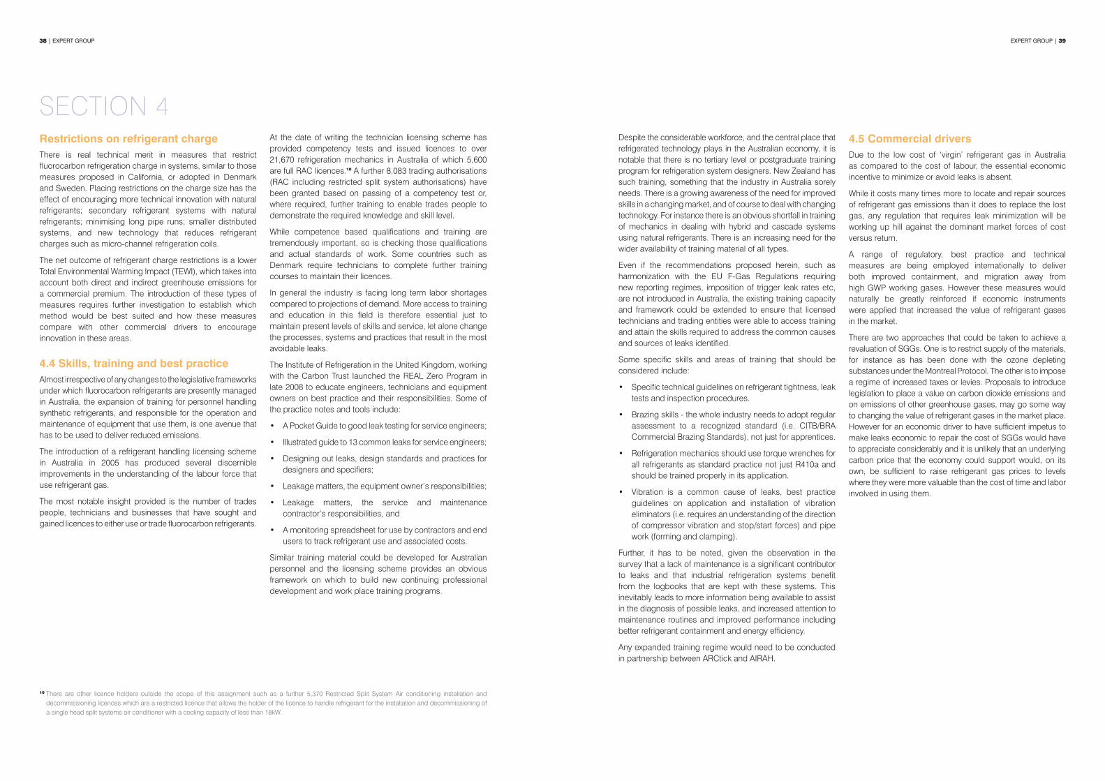
38 | EXPERT GROUP EXPERT GROUP | 39
Despite the considerable workforce, and the central place that refrigerated technology plays in the Australian economy, it is notable that there is no tertiary level or postgraduate training program for refrigeration system designers. New Zealand has such training, something that the industry in Australia sorely needs. There is a growing awareness of the need for improved skills in a changing market, and of course to deal with changing technology. For instance there is an obvious shortfall in training of mechanics in dealing with hybrid and cascade systems using natural refrigerants. There is an increasing need for the wider availability of training material of all types.
Even if the recommendations proposed herein, such as harmonization with the EU F-Gas Regulations requiring new reporting regimes, imposition of trigger leak rates etc, are not introduced in Australia, the existing training capacity and framework could be extended to ensure that licensed technicians and trading entities were able to access training and attain the skills required to address the common causes and sources of leaks identified.
Some specific skills and areas of training that should be considered include:
• Specific technical guidelines on refrigerant tightness, leak tests and inspection procedures.
• Brazing skills - the whole industry needs to adopt regular assessment to a recognized standard (i.e. CITB/BRA Commercial Brazing Standards), not just for apprentices.
• Refrigeration mechanics should use torque wrenches for all refrigerants as standard practice not just R410a and should be trained properly in its application.
• Vibration is a common cause of leaks, best practice guidelines on application and installation of vibration eliminators (i.e. requires an understanding of the direction of compressor vibration and stop/start forces) and pipe work (forming and clamping).
Further, it has to be noted, given the observation in the survey that a lack of maintenance is a significant contributor to leaks and that industrial refrigeration systems benefit from the logbooks that are kept with these systems. This inevitably leads to more information being available to assist in the diagnosis of possible leaks, and increased attention to maintenance routines and improved performance including better refrigerant containment and energy efficiency.
Any expanded training regime would need to be conducted in partnership between ARCtick and AIRAH.
4.5 Commercial drivers Due to the low cost of ‘virgin’ refrigerant gas in Australia as compared to the cost of labour, the essential economic incentive to minimize or avoid leaks is absent.
While it costs many times more to locate and repair sources of refrigerant gas emissions than it does to replace the lost gas, any regulation that requires leak minimization will be working up hill against the dominant market forces of cost versus return.
A range of regulatory, best practice and technical measures are being employed internationally to deliver both improved containment, and migration away from high GWP working gases. However these measures would naturally be greatly reinforced if economic instruments were applied that increased the value of refrigerant gases in the market.
There are two approaches that could be taken to achieve a revaluation of SGGs. One is to restrict supply of the materials, for instance as has been done with the ozone depleting substances under the Montreal Protocol. The other is to impose a regime of increased taxes or levies. Proposals to introduce legislation to place a value on carbon dioxide emissions and on emissions of other greenhouse gases, may go some way to changing the value of refrigerant gases in the market place. However for an economic driver to have sufficient impetus to make leaks economic to repair the cost of SGGs would have to appreciate considerably and it is unlikely that an underlying carbon price that the economy could support would, on its own, be sufficient to raise refrigerant gas prices to levels where they were more valuable than the cost of time and labor involved in using them.
Restrictions on refrigerant chargeThere is real technical merit in measures that restrict fluorocarbon refrigeration charge in systems, similar to those measures proposed in California, or adopted in Denmark and Sweden. Placing restrictions on the charge size has the effect of encouraging more technical innovation with natural refrigerants; secondary refrigerant systems with natural refrigerants; minimising long pipe runs; smaller distributed systems, and new technology that reduces refrigerant charges such as micro-channel refrigeration coils.
The net outcome of refrigerant charge restrictions is a lower Total Environmental Warming Impact (TEWI), which takes into account both direct and indirect greenhouse emissions for a commercial premium. The introduction of these types of measures requires further investigation to establish which method would be best suited and how these measures compare with other commercial drivers to encourage innovation in these areas.
4.4 Skills, training and best practice Almost irrespective of any changes to the legislative frameworks under which fluorocarbon refrigerants are presently managed in Australia, the expansion of training for personnel handling synthetic refrigerants, and responsible for the operation and maintenance of equipment that use them, is one avenue that has to be used to deliver reduced emissions.
The introduction of a refrigerant handling licensing scheme in Australia in 2005 has produced several discernible improvements in the understanding of the labour force that use refrigerant gas.
The most notable insight provided is the number of trades people, technicians and businesses that have sought and gained licences to either use or trade fluorocarbon refrigerants.
At the date of writing the technician licensing scheme has provided competency tests and issued licences to over 21,670 refrigeration mechanics in Australia of which 5,600 are full RAC licences.10 A further 8,083 trading authorisations (RAC including restricted split system authorisations) have been granted based on passing of a competency test or, where required, further training to enable trades people to demonstrate the required knowledge and skill level.
While competence based qualifications and training are tremendously important, so is checking those qualifications and actual standards of work. Some countries such as Denmark require technicians to complete further training courses to maintain their licences.
In general the industry is facing long term labor shortages compared to projections of demand. More access to training and education in this field is therefore essential just to maintain present levels of skills and service, let alone change the processes, systems and practices that result in the most avoidable leaks.
The Institute of Refrigeration in the United Kingdom, working with the Carbon Trust launched the REAL Zero Program in late 2008 to educate engineers, technicians and equipment owners on best practice and their responsibilities. Some of the practice notes and tools include:
• A Pocket Guide to good leak testing for service engineers;
• Illustrated guide to 13 common leaks for service engineers;
• Designing out leaks, design standards and practices for designers and specifiers;
• Leakage matters, the equipment owner’s responsibilities;
• Leakage matters, the service and maintenance contractor’s responsibilities, and
• A monitoring spreadsheet for use by contractors and end users to track refrigerant use and associated costs.
Similar training material could be developed for Australian personnel and the licensing scheme provides an obvious framework on which to build new continuing professional development and work place training programs.
SECTION 4
10 There are other licence holders outside the scope of this assignment such as a further 5,370 Restricted Split System Air conditioning installation and decommissioning licences which are a restricted licence that allows the holder of the licence to handle refrigerant for the installation and decommissioning of a single head split systems air conditioner with a cooling capacity of less than 18kW.
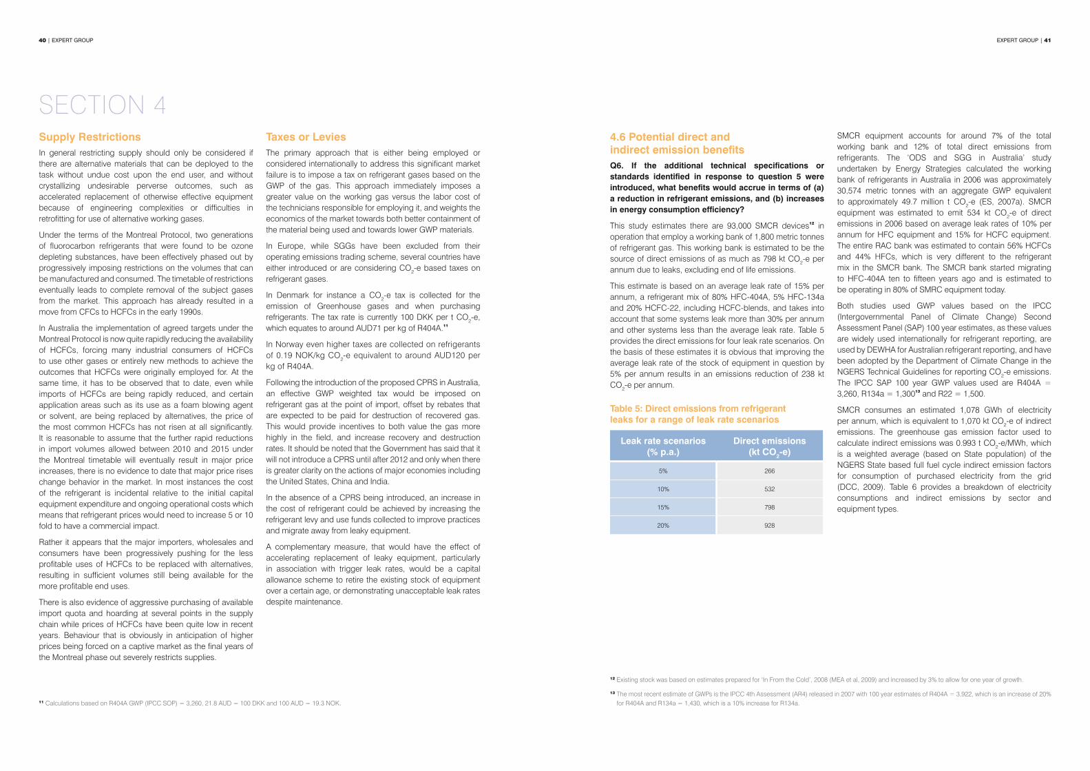
40 | EXPERT GROUP EXPERT GROUP | 41
4.6 Potential direct and indirect emission benefitsQ6. If the additional technical specifications or standards identified in response to question 5 were introduced, what benefits would accrue in terms of (a) a reduction in refrigerant emissions, and (b) increases in energy consumption efficiency?
This study estimates there are 93,000 SMCR devices12 in operation that employ a working bank of 1,800 metric tonnes of refrigerant gas. This working bank is estimated to be the source of direct emissions of as much as 798 kt CO2-e per annum due to leaks, excluding end of life emissions.
This estimate is based on an average leak rate of 15% per annum, a refrigerant mix of 80% HFC-404A, 5% HFC-134a and 20% HCFC-22, including HCFC-blends, and takes into account that some systems leak more than 30% per annum and other systems less than the average leak rate. Table 5 provides the direct emissions for four leak rate scenarios. On the basis of these estimates it is obvious that improving the average leak rate of the stock of equipment in question by 5% per annum results in an emissions reduction of 238 kt CO2-e per annum.
Table 5: Direct emissions from refrigerant leaks for a range of leak rate scenarios
Leak rate scenarios (% p.a.)
Direct emissions (kt CO2-e)
5% 266
10% 532
15% 798
20% 928
SMCR equipment accounts for around 7% of the total working bank and 12% of total direct emissions from refrigerants. The ‘ODS and SGG in Australia’ study undertaken by Energy Strategies calculated the working bank of refrigerants in Australia in 2006 was approximately 30,574 metric tonnes with an aggregate GWP equivalent to approximately 49.7 million t CO2-e (ES, 2007a). SMCR equipment was estimated to emit 534 kt CO2-e of direct emissions in 2006 based on average leak rates of 10% per annum for HFC equipment and 15% for HCFC equipment. The entire RAC bank was estimated to contain 56% HCFCs and 44% HFCs, which is very different to the refrigerant mix in the SMCR bank. The SMCR bank started migrating to HFC-404A ten to fifteen years ago and is estimated to be operating in 80% of SMRC equipment today.
Both studies used GWP values based on the IPCC (Intergovernmental Panel of Climate Change) Second Assessment Panel (SAP) 100 year estimates, as these values are widely used internationally for refrigerant reporting, are used by DEWHA for Australian refrigerant reporting, and have been adopted by the Department of Climate Change in the NGERS Technical Guidelines for reporting CO2-e emissions. The IPCC SAP 100 year GWP values used are R404A = 3,260, R134a = 1,30013 and R22 = 1,500.
SMCR consumes an estimated 1,078 GWh of electricity per annum, which is equivalent to 1,070 kt CO2-e of indirect emissions. The greenhouse gas emission factor used to calculate indirect emissions was 0.993 t CO2-e/MWh, which is a weighted average (based on State population) of the NGERS State based full fuel cycle indirect emission factors for consumption of purchased electricity from the grid (DCC, 2009). Table 6 provides a breakdown of electricity consumptions and indirect emissions by sector and equipment types.
Supply Restrictions In general restricting supply should only be considered if there are alternative materials that can be deployed to the task without undue cost upon the end user, and without crystallizing undesirable perverse outcomes, such as accelerated replacement of otherwise effective equipment because of engineering complexities or difficulties in retrofitting for use of alternative working gases.
Under the terms of the Montreal Protocol, two generations of fluorocarbon refrigerants that were found to be ozone depleting substances, have been effectively phased out by progressively imposing restrictions on the volumes that can be manufactured and consumed. The timetable of restrictions eventually leads to complete removal of the subject gases from the market. This approach has already resulted in a move from CFCs to HCFCs in the early 1990s.
In Australia the implementation of agreed targets under the Montreal Protocol is now quite rapidly reducing the availability of HCFCs, forcing many industrial consumers of HCFCs to use other gases or entirely new methods to achieve the outcomes that HCFCs were originally employed for. At the same time, it has to be observed that to date, even while imports of HCFCs are being rapidly reduced, and certain application areas such as its use as a foam blowing agent or solvent, are being replaced by alternatives, the price of the most common HCFCs has not risen at all significantly. It is reasonable to assume that the further rapid reductions in import volumes allowed between 2010 and 2015 under the Montreal timetable will eventually result in major price increases, there is no evidence to date that major price rises change behavior in the market. In most instances the cost of the refrigerant is incidental relative to the initial capital equipment expenditure and ongoing operational costs which means that refrigerant prices would need to increase 5 or 10 fold to have a commercial impact.
Rather it appears that the major importers, wholesales and consumers have been progressively pushing for the less profitable uses of HCFCs to be replaced with alternatives, resulting in sufficient volumes still being available for the more profitable end uses.
There is also evidence of aggressive purchasing of available import quota and hoarding at several points in the supply chain while prices of HCFCs have been quite low in recent years. Behaviour that is obviously in anticipation of higher prices being forced on a captive market as the final years of the Montreal phase out severely restricts supplies.
Taxes or LeviesThe primary approach that is either being employed or considered internationally to address this significant market failure is to impose a tax on refrigerant gases based on the GWP of the gas. This approach immediately imposes a greater value on the working gas versus the labor cost of the technicians responsible for employing it, and weights the economics of the market towards both better containment of the material being used and towards lower GWP materials.
In Europe, while SGGs have been excluded from their operating emissions trading scheme, several countries have either introduced or are considering CO2-e based taxes on refrigerant gases.
In Denmark for instance a CO2-e tax is collected for the emission of Greenhouse gases and when purchasing refrigerants. The tax rate is currently 100 DKK per t CO2-e, which equates to around AUD71 per kg of R404A.11
In Norway even higher taxes are collected on refrigerants of 0.19 NOK/kg CO2-e equivalent to around AUD120 per kg of R404A.
Following the introduction of the proposed CPRS in Australia, an effective GWP weighted tax would be imposed on refrigerant gas at the point of import, offset by rebates that are expected to be paid for destruction of recovered gas. This would provide incentives to both value the gas more highly in the field, and increase recovery and destruction rates. It should be noted that the Government has said that it will not introduce a CPRS until after 2012 and only when there is greater clarity on the actions of major economies including the United States, China and India.
In the absence of a CPRS being introduced, an increase in the cost of refrigerant could be achieved by increasing the refrigerant levy and use funds collected to improve practices and migrate away from leaky equipment.
A complementary measure, that would have the effect of accelerating replacement of leaky equipment, particularly in association with trigger leak rates, would be a capital allowance scheme to retire the existing stock of equipment over a certain age, or demonstrating unacceptable leak rates despite maintenance.
SECTION 4
11 Calculations based on R404A GWP (IPCC SOP) = 3,260, 21.8 AUD = 100 DKK and 100 AUD = 19.3 NOK.
12 Existing stock was based on estimates prepared for ‘In From the Cold’, 2008 (MEA et al, 2009) and increased by 3% to allow for one year of growth.
13 The most recent estimate of GWPs is the IPCC 4th Assessment (AR4) released in 2007 with 100 year estimates of R404A = 3,922, which is an increase of 20% for R404A and R134a = 1,430, which is a 10% increase for R134a.

42 | EXPERT GROUP EXPERT GROUP | 43
Operational performance, electricity consumption and direct emissions can be affected by more than 30% if a system is not ‘critically charged’ with an ideal amount of refrigerant. A study performed by the Department of Mechanical Engineering, Brunel University, in the UK on a 4 kW nominal cooling capacity vapor compression water-to-water chiller, found it could operate over a wide range of charge levels, 25% below to 25% above the ‘critical charge’ without significant impact on its performance. Outside this range, the performance of the chiller was found to be strongly dependent upon the charge level with the coefficient of performance dropping from around 2.5 to 2.2 with 140% of charge, and 1.6 with 50% of charge, which equates to a 36% drop in efficiency (Grace et al, 2004).
In a regulatory impact statement prepared in the UK by the Department for Environment, Food and Rural Affairs (DEFRA) in 2008 they concluded the implementation of better leak checking procedures could have a significant environmental benefits which include both ‘direct’ savings (i.e. reduced emissions of HFC refrigerants) and ‘indirect’ savings (i.e. reduced energy consumption). The assessment estimated a conservative energy savings in the range of 3% to 6% through the leak testing regime (DEFRA, 2008).
However improved maintenance practices that check, prevent and repair leaks would not only assist in maintaining efficient refrigerant charges and thus closer to optimal electrical efficiency, it is likely that other energy efficiency opportunities will be found such as blocked air cooled condensers and dirty evaporators.
The ‘In From The Cold’ study of non-domestic refrigeration in 2009 found that improved maintenance practices could easily achieve a 10% improvement in operational efficiency, and with some equipment can eliminate as much as half their direct emissions (MEA et al, 2009). An improvement in operational efficiency of SMCR equipment by 5% to 10% equates to reduction of emissions from energy use of 64 to 128 kt CO2-e per annum.
The inherent difficulty in measuring the financial benefit of improved refrigeration maintenance practices remains a significant obstacle to reducing emissions from existing stock. Without regulatory measures and proven practices, finance managers are often reticent to pay to fix something that appears to be working.
The current market structure poses another significant barrier as the majority of SMCR equipment is owned, installed and maintained by small to medium enterprises (end users and contractors) driven by short term financial objectives. Walk in coolrooms in the catering and hospitality sector represent around 50% of all SMRC equipment by quantity (MEA et al, 2009). Businesses in this sector typically have high ownership turnover and restricted cash flows, which leads to a lack of maintenance.
Table 6: Electricity consumption and indirect emissions for SMCR by sector and equipment type.
Sector Equipment typesIndirect emissions
(electricity consumed)
GWh p.a. kt CO2-e
Catering and hospitality (incl. pubs, clubs and hotels)
Walk in coolrooms
477 474
Retail food and liquor retailing 152 151
Cool rooms (primary industry) 226 224
Cold storage distribution 57 56
Clubs, Pubs, hotels and entertainment venues Beer chilling equipment 121 120
Food merchandising (incl. small supermarkets) Retail display cases with remote condensing units 103 102
Total 1,135 1,127
SECTION 4
The proposed changes to regulations, technical measures and work practices could certainly reduce annual leaks rates from an estimated 15% p.a. under current measures to 10%. A target of 5% is not unrealistic if a comprehensive mix of policy, regulatory, fiscal and training measures were implemented.

44 | EXPERT GROUP EXPERT GROUP | 45
FINDINGS FROM REPORT
• Australian Standards Committee ME-006 Refrigeration responsible for the governing refrigeration standard AS/NZS 1677-1998 Refrigerating systems, Part 1 and 2 to update or replace this standard with a standard that covers the current range of refrigerants, refrigerant tightness and maintenance practices. ISO 5149: 2009 which is very similar to EN 378: 2008 is compatible with EU F-Gas Regulations (i.e. includes leak test procedures) and is considered by Australian industry as the most suitable replacement.
• The Australia and New Zealand Refrigerant Handling Code of Practice to be revised to harmonize with F-Gas Regulations procedures for refrigerant tightness, leak tests, inspection and requirement to repair or replace. This will involve mandatory leak testing of SMCR with a refrigerant charge 3 kg (or 6 kg if hermetically sealed) and operators to maintain records (log books) on the quantity and type of gas installed, and any quantities added, and the quantity recovered during servicing, maintenance and final disposal. The leak checking frequencies (refrigerant charge 3 kg annually, 30 kg every six months and 300 kg quarterly) and recording requirements implemented in the UK are preferred. These systems are not registered and logbook records must be made available on request by authorities.
• DEWHA Ozone and SGG Team to establish a Specialist Technical panel either in conjunction with the review of the Code of Practice, or a subcommittee to review the merits of incorporating technical suggestions from industry outlined in Table 4 such as the elimination of flared connections, minimising the use of Schrader valves and improving the minimum design and test standard of evaporators and condensers used on SMCR equipment.
• Introduce maximum allowable leak rates or trigger rates as a complementary measure to improved containment practices. The level of the trigger rates and actions following a breach are to be determined pending the outcome of the review by the European Commission in July 2011.
• DEWHA Ozone and SGG Team to participate in Best Practice in Refrigeration Working Group established by the Equipment Energy Efficiency (E3) Committee under the auspices of the Australian and New Zealand Ministerial Council for Energy (MCE) to improve the selection, installation, commissioning and maintenance of refrigeration equipment. Poor maintenance practices have been identified as a key source of direct and indirect emissions, and therefore have synergies with improved refrigerant containment.
• The Specialist Technical panel established pursuant to above recommendation to produce a list of priority areas of training required and refer that to the Best Practice in Refrigeration Working Group, ARCTick and AIRAH for review and implementation through TAFE and competency training programs.
• Noting the significant implications of the market failure in regard to the economic drivers that leaves equipment owners with almost no option but to ‘live with leaks’, DEWHA Ozone and SGG Team to vigorously explore all policy options for improving the economics of containment, synthetic refrigerant recovery and encouraging technical innovation with natural refrigerants and other means to reduce fluorocarbon refrigerant charges.
The above recommendations involve a review of the current governing technical Standard, Code of Practice, and possibly regulations. It is therefore advisable to establish a Work Plan that outlines which items could be implemented immediately and those that require a more involved review process.
RECOMMENDATIONS

46 | EXPERT GROUP EXPERT GROUP | 47
REFERENCESAS/NZ 1677-1998 AS/NZ 1677-1998 Refrigerating systems, Part 1 and 2, Standards Australia, 1998
BRA, 2007 Code of Practice for Refrigerant Leak Tightness in Compliance with F-Gas Regulations, published by the British Institute of Refrigeration (BRA) and the Association of the Federation of Environmental Trade Associations (FETA), version 1, December 2007
CARB, 2009 Proposed Regulation Order for Regulation for the Management of High Global Warming Potential Refrigerants for Stationary Sources, and the Resolution (December 2009), State of California Air Resources Board, 2009
Code of Practice, 2007 Australia and New Zealand Refrigerant handling code of practice 2007, Part 2 Systems other than self-contained low charge systems, prepared by AIRAH and the Institute of Refrigeration, Heating and Air Conditioning Engineers New Zealand, 2007
DME, 2009 Fact sheet no. 46: Industrial greenhouse gases: HFCs, PFCs and SF6, prepared by the Danish Ministry of the Environment, 2009
DEFRA, 2008 Impact Assessment of the Fluorinated Greenhouse Gases Regulations 2009, prepared by the Department for Environment, Food and Rural Affairs, November 2008
EC 842/2006European Commission (EC) Regulation 516/2007, pursuant to EC Regulation EC 842/2006 of the European Parliament and of the Council, standard leakage checking requirements for stationary refrigeration, air conditioning and heat pump equipment containing certain fluorinated greenhouse gases
ENDS, 2010 EU set to achieve F-Gas emission reduction target, ENDS Europe Daily press release, January 2010
ES, 2007a Assessment of the HCFC Bank and Forecasts of Future Demand for DEWHA Ozone & Synthetic Gas Team, prepared by Michael McCann and Peter Brodribb for Energy Strategies, September 2007
ES, 2007b Cold Hard Facts, prepared by Energy Strategies in association with Expert Group for DEWHA and Refrigerants Australia, 2007
ES, 2008 ODS and SGGs in Australia; A study of End Uses, Emissions and Opportunities for Reclamation, prepared by Energy Strategies in association with Expert Group for the Department of Environment, Heritage, Water & the Arts, June 2008
EES UOG, 2006 Mitigating GHG emissions from cooling applications in Germany, University of Groningen. IVEM, Centre for Energy and Environmental Studies by Jan Ostendarp, 2006
FEA, 2009 Comparative Assessment of the Climate Relevance of Supermarket Refrigeration Systems and Equipment, prepared by Ecofys Germany GmbH, Prof. Dr. Michael Kauffeld and Dr. André Leisewitz for the Federal Environment Agency (Germany), 2009
F-Gas 842/2006 EC F-Gas Regulation 842/2006
F-Gas Support, 2008 Information Sheets RAC 1 to 6, prepared by F-Gas Support, 2008
Grace et al, 2004 Sensitivity of refrigeration system performance to charge levels and parameters for on-line leak detection, I.N. Grace, D. Datta and S.A. Tassou, Department of Mechanical Engineering, Brunel University, Uxbridge, Middlesex UB8 3PH, United Kingdom, 2004
IEEP, 2005 Is STEK as good as reported? Uncertainties in the concept underlying the proposed European Regulation on fluorinated gases, prepared by J. Anderson for the Institute for European Environmental Policy, 2005
IOR, 2008 Industry Presentation, Institute of Refrigeration in the UK, 2008
IOR, 2009 Illustrated guide to 13 Common Leaks, the Institute of Refrigeration in the UK and the Carbon Trust as part of the REAL Zero program, 2009
IPCC, 2006 IPCC Good Practice Guidelines and Uncertainty Management in National Greenhouse Gas Inventories, International Panel of Climate Change, 2006
LACORS, 2007UK Implementation of Fluorinated Greenhouse Gases and Ozone-Depleting Substances Regulations, Market intelligence and risk-based implementation model, prepared by the Local Authorities Coordinators of Regulatory Services) (LACORS) in association with the Department for Environment, Food and Rural Affairs (DEFRA), November 2007
MEA et al, 2009 Draft Non-Domestic Energy Efficiency Strategy: In from the Cold, prepared by Mark Ellis, Peter Brodribb, Tony Fairclough, Rod King and Kevin Finn for DEWHA, 2009
QGDME, 2009 Hydrocarbon Appliance Register, Queensland Government, Department of Mines and Energy, 2009
A summary of the primary sources and causes of refrigerant leaks described as the ‘dirty dozen’ is provided in Table 7 to emphasize where technical, regulatory and commercial measures need to target in order to deliver practical sustainable outcomes.
Table 7: The primary sources and causes of refrigerant leaks in SMCR
The ‘dirty dozen’
1. Flared connections commonly used on components such as filter driers, TX valves, solenoid valves, sight glasses, check valves and pressure regulator controls (crankcase and evaporator).
2. Lack of regular service, maintenance and leak testing.
3. Failure of condenser and evaporators, particularly on return bends.
4. Poor installation (i.e. vibration elimination and pipe support).
5. Schrader valves (i.e. uncapped and overused by industry).
6. Poor installation (i.e. brazing).
7. Old equipment overdue for replacement, particularly open drive equipment with leaky shaft seals.
8. Service valves (i.e. uncapped, plastic caps and wear of glad/spindle/overheated during installation).
9. Pressure switch connections (i.e. PVC flexible lines and capillary lines).
10. Corrosion, particularly on condensate tray pipe work, evaporators and outdoor condensers.
11. Mechanical joints and flanges.
12. Inferior quality equipment, particularly cheap imports.
RECOMMENDATIONS

48 | EXPERT GROUP EXPERT GROUP | 49
APPENDIX I: COPY OF SURVEY QUESTIONNAIRE
1. Sources of refrigerant leaks?
Which of the following sources of leaks have you or your technicians experienced or repaired in the past 12 months (if solo contractor last 24 months), please tick indicate with (Y/N)
1. Shut off and ball valves 11. Piercing and line tap valves 2. Schrader valves 12. Pressure switches connections 3. Flare joints 13. O-rings 4. Brazed joints 14. Copper capillary tubes 5. Mechanical joints (e.g. flanges on filter driers) 15. PVC flexible hose lines on HP/LP 6. Pressure relief valves (over-pressure protection) 16. Condensate tray pipe work 7. Fusible plugs (over-pressure protection) 17. Thermostatic Expansion Valve 9. Shaft seals (open type compressors) 18. Leakage from a compressor body 9. Condenser failure 19. Other, please comment below: 10. Return bends on evaporators or condensers
2. Causes of refrigerant leaks?Which of the following causes of leaks are the most common, please nominate top 10 ONLY where 1 is the most common cause of leaks?
1. Poor brazing 11. Uncapped valves 2. Poor vibration elimination 12. Uncapped Schrader valves 3. Insufficient pipe support 13. Valve core damaged during brazing 4. Pipe clamps that cause wear and rub through 14. Wear of valve packing gland 5. Mechanical joints (flares on driers) 15. Wear of valve spindle 6. Wrong pipe thickness (design) 16. Poor design (condensing units and evaporators) 7. Wrong pipe thickness (installation) 17. Poor installation 8. Lack of regular service and maintenance 18. Use of incorrect refrigerant
9. Poor access making servicedifficult (concealed pipework)
19. Insufficient leak testing duringinstallation or service
10. Corrosion of condenser 20. Equipment replacement overdue 21. Other, please comment below:
ACKNOWLEDGEMENTSThe authors would like to thank the RACCA and AREMA members, and other industry experts that have provided invaluable information and advice during the course of preparing the study into the sources and causes of refrigerant leaks.
Roger Stringer National Technical Manager Actrol
Andrew AmbroseManaging Director - Asia Pacific and Chairman of Refrigerants Australia (RA)
A-Gas International plc
Mike Hettrick Technical Manager A-Gas (Aust) Pty Ltd
Francis Burraston Quality and Compliance Manager A-Gas (UK) Ltd
Graeme Stuart General Manager, Greenhalgh Asia Pacific Advanced Refrigeration Technologies
Steve Anderson PresidentAir Conditioning & Refrigeration Equipment Manufacturers Association of Australia and RA
Stephen Mc Martin Designer Auscoil Pty Ltd
Dr Rafiqul Islam Technical Manager Austral Refrigeration
Kylie Farrelley Product Manager Arkema Pty Ltd
George Thompson National Training and Compliance Manager ARCtick
Clive Shaw Senior Technical Auditor ARCtick
Pat Bourke National Engineering and Marketing Manager Bitzer Australia
Julian Hudson Engineering Manager Bitzer Australia
Ron Sporton Technical Manager Danfoss (Australia) Pty Ltd
John Mc CormackBusiness Manager, Industrial Chemicals and Chairman of Refrigerant Reclaim Aust.
DuPont (Australia) Limited
Dr Ladas Taylor Technical Manager Energy Resources Group
Kevin Lee Global Technical Manager Heatcraft Worldwide Refrigeration
Colin Crowl Market Manager, Commercial Refrigeration Heatcraft Australia
Anthony Harrigan Market Manager, Refrigerants Heatcraft Australia
Pete Schey General Manager Muller Industries
Peter Frey Managing Director Recom Australia
Kevin O’Shea President Refrigeration and Air Conditioning Contractors Association
Ross Piper Secretary (NSW) Refrigeration and Air Conditioning Contractors Association
Michael Bennett General Manager Refrigerant Reclaim Australia
Stefan Jensen Managing Director Scantech Refrigeration Technologies
Ross Oxely Director Yarra Valley Refrigeration Service
3. Solutions?
Any suggestions to minimise refrigerant leaks? Please comment below.

50 | EXPERT GROUP EXPERT GROUP | 51
APPENDIX II: INDUSTRY SURVEY, SUGGESTIONS AND COMMENTSThe table below provides a list of all of the comments and suggestions received from RACCA members surveyed. These comments include minor grammatical edits and omit any references to company names or participants providing the feedback.
Comments and suggestions from industry
Regular leak testing and replacement of open drive systems.
Regular servicing (quality control) by qualified mechanics, not just installers.
Compulsory LP switches to systems.
Improve manufacturing, installation and length of pressure test before commissioning.
Clients need to be more enthusiastic about maintenance, and investments of plant equipment.
Stop the importations of cheap Chinese components (e.g. Evaporators used by manufacturers).
Eliminating cheap/inferior products and installation.
Allow more time on installations for leak testing.
Teflon tape on outlet of TX valves (suction line), most leaks occur here.
Leak sealer seems to work well on small to large units and continues to circulate provided oil separator is not too efficient.
Better installation practices.
Better design of systems with easy access. Staff training/education, improve quality control and standards.
Discharge and suction pipes too short and tight after compressor resulting in cracked pipes. Education to get mechanics to take more care.
Crack down on unlicensed AC installers servicing major retailers that do careless pipe work.
Make the customer responsible for their unit and whom they use to install. Seller of unit to keep record of installer licence details. Make servicing mandatory for commercial equipment; enforce existing rules.
Weld as many joints as possible instead of flares and service equipment regularly.
Replace all flare fittings with soldered fittings. Replace open drive compressors with semi or hermetic compressors. Make it law that all businesses carry out an annual service on refrigeration and AC equipment.
Make 410A pipe the standard for all pipe installs and standard on all condensing units regardless of which gas it is running on.
Corrosion and electrolysis evaporator coils, less flare fittings. Thicker return bends and tubing evaporators. Eliminate gland and capped valves.
Thin copper pipes leaning against inside condenser and evaporator coils.
Manufacturers need to use thicker walled pipe in evaporators and higher quality materials.
Other source of leaks: Reversing Valve body.
Braze weld all joints including TX valves and driers. All my installs have welded joints and rarely have problems with leaks.
Better overall quality of installation (pipe support), programmed maintenance, reduction of joints, in older systems-electronic control.
Educate farmers that any open type compressor should have the shaft seal replaced every 4 to 5 years as they seem to fail around 5 to 6 years. Educate repairers that a close inspection should be carried of all pipe work on a regulator basis (e.g. every 6 months). Educate shop owners that they should service their refrigeration equipment and not wait for a failure to service the system. Use corrosion protection on evaporators when installing new systems (e.g. cabinets) in storage areas that contain types of food that give of vapors that effect the refrigerant piping. Create a regulation that evaporator coils should be made from a specific grade or thickness of tubing, thus preventing pitting of the U bends.
Other source: Return bend leaks due to age of equipment. Service and maintenance is neglected in fruit growing areas due to drought conditions and cost of water.
Mandatory maintenance of split system air conditioning units containing R22, suggest two visits per annum.
Do the job right the first time. It’s called common sense.
Units should be maintained and not left to break down due to leaks.
Comments and suggestions from industry
Stop allowing cheap units into the country, and prevent unlicensed people installing units.
Take more time and effort for installation and service.
Pressure test systems at 6,000 kPa. Set higher standards of equipment and parts.
Good work practice and regular maintenance.
Quality of evaporators and condensers need to be upgraded from manufacturers, poor quality flare fittings (e.g. flare nuts). Regular maintenance.
Better community education informing people of the legalities of using non qualified personnel to carry installation and servicing of refrigeration equipment.
Leak test all flares on installation and joints. Cracked flare nuts are also common.
Rust holes on steel suction service valves.
Only licensed refrigeration mechanic to install pipe work.
Training on proper flaring techniques. Upgrade status of Refrigeration Mechanics by general advertising to allow mechanics to take longer and charge for the better quality repair. Cheap and unreliable spare parts need to be weeded out of the parts market (e.g. cheap hand valves, poor quality motors, pressure control flex lines that deteriorate from UV in 3 months).
Industry needs to impose stricter measures and the government to look at our trade seriously.
More maintenance.
Will not use PVC flexible hose lines on HP/LP. Every company should have there own procedure manual outlining correct procedures. Encourage better training through apprentices from the start. Stop recognising international licences as qualified. Overseas tradesmen in my experience are more than likely not qualified to Australian levels.
Yes-police the industry, stop electricians from installing A/C equipment. Most of the leaks were on new installations done by non-qualified installers.
Stop leaks with regular check ups and maintenance.
Tax breaks to replace old systems to encourage owners to upgrade systems.
Do your job properly is the easiest solution. Don’t rush to try and compete with opposition quotes. Mechanics chase money in jobs and don’t have the expertise to back them up, job pride is decreased.
Introduce a system to force end users to maintain their equipment at least twice a year minimum.
The main causes of leaks are evaporators and expansion valve flares - evaporator leaks are from expansion and contraction. Also food acid corroding through the copper pipes. Expansion line flares did not leak when we could purchase grooved flare nuts. Not available any more.
Standardize pipe thicknesses for refrigeration practice, not cheap import.
Make it acceptable to use a small amount of refrigerant and boost pressure with nitrogen to do a good leak job.
Some cabinets have condensing units and TX valves that are hard to access. Lack of maintenance is a major cause - mostly on older units.
Installation without due consideration to subsequent repairs. Outside units set in poor locations make it virtually impossible to repair. So they have to be “un-installed” then fixed at ground level and then reinstalled.
Installation contractors should be required to certify the systems are free from leaks after commissioning. Incorrect certification would result in demerit points and eventual loss of licence for repeat offenders.
Take pride in our work.
Try to get customers on main contracts. Better quality equipment. Too much equipment coming into Aust. that is of a very poor quality with very thin copper.
Steel line suction valves/fittings rust out, and loose gas-solution use brass/stainless.
Main reason for failures is lack of regular maintenance. Mandate for routine service.

52 | EXPERT GROUP EXPERT GROUP | 53
Comments and suggestions from industry
Work carried out by certificate 2 installers over cert 3 technicians. More training for cert 2 installers and relay importance of regular servicing to customers.
Customers need to be proactive on maintenance instead of breakdown.
Most common cause, pitted out evaporator return bends in cool room and cabinet coolers. Light gauge copper tube and bends, poor brazing. Replace old equipment. Revise standards on evaporator coil construction to prevent corrosion of copper tubes. Use more brazed joints (on TX valves). Provide more access points on small to medium hermetic systems (i.e. shut off valves, service valves etc.).
Only allow “fully trained” and qualified technicians to install and work on equipment having a full refrigeration and A/C licences.
During regular services more time need to be allocated to leak testing - clients do not want to spend on this.
More emphasis on correct procedures and training.
Full service and not worry so much about present life during work time. Also do repairs correctly the first time. The younger technicians of today worry more about their pay than the clients’ needs. Many times we have found because the client did not want to spend the money on installations we found installers have not carried out correct installation practice. Also with regards to servicing the technicians sometimes rush through which at times is not their fault.
Heavier gauge tube similar to gauge used in Buffalo Trident evaporator coils. As we work in the coastal area I do think the paint job on compressor could be improved in preparation.
Better training and attitude towards finding and repairing faults (i.e. 2kg R404A = 1 hour of labor). Customer Responsibility - Due to current attitudes towards service costs and hourly rates by major users in the industry, the quality of the installation and breakdown service is dictated by the price they are prepared to pay. Until realistic cost-recovery is addressed, all the new regulations and laws will have a negligible effect in addressing refrigerant leakage.
Regular preventative maintenance by reliable contractors. Brazed components in lieu of flare connectors.
Ensure that lowest priced tenders meet minimum requirements - including sub standard refrigeration equipment.
More robust evaporators, better shaft seal design. Get rid of plumbers and anyone with an “AC qualification” that does not have a refrigeration apprenticeship.
Eliminate from the industry ASAP poorly trained and unlicenced tradesmen mainly with split licences trying their hand at a bit of refrigeration work.
Stop plumbers and electricians with split licences working on this equipment.
Regular maintenance.
Use solder TX valves especially on pump down systems. A lot of evaporators with leaks on return bends - should have thicker copper.
Improve quality control. Stop allowing OEM using steel flare nuts in lieu of brass. Corrosion in these fittings is very bad.
Greater training of staff/technicians is a great idea, both at TAFE and in-house. Essentially fridgies should be retested every 12 months to ensure competency with service, repairs and installations. Every technician thinks they are the best, however they need to be told the truth and punished if poor work practices present.
Stricter controls over servicing and maintenance (Aust. Standards and Legislation). Inspection of installation by qualified inspectors as with electrical work.
Ban restricted licences. Food acid corrosion protection to evaporators.
Stricter training at apprentice level. Better coil design (i.e. thicker tubing on evaporators). Also corrosion treatment. Better quality control on imported products (i.e. cabinets and components from Asia).
Use standard installation instructions. Always use skilled and trained persons for all kind of installations. Also confirm the selection of materials comply with the relevant standards. Use manufacturers recommendations always.
Vacuum analysis-pull down to hold 500-300 microns. Pressure test with nitrogen once leak is repaired. Too common it is that technicians find one leak, fix it and then pull a 30 min vacuum and then charge the system when there are other leaks in the system). Make leak detectors mandatory if you hold an ARCtick licence. Best leak detectors on the market are $800 that will pick a leak a lot quicker but half of fridges could not afford. Possible financial support.
Teaching apprentices how to flare and braze pipework properly.
All contractors must complete a full apprenticeship before obtaining any type of refrigerant handling licence, including split system AC work.
A lot of O rings in valve bodies appear to be breaking down with synthetic oils.
APPENDIX II: INDUSTRY SURVEY, SUGGESTIONS AND COMMENTS Cont.
EMPTY PAGE
Prepared by Expert Group (A.C.N. 122 581 159) Authors: Peter Brodribb and Michael McCann P 61 3 9592 9111F 61 3 9592 1846E [email protected]