refrigerant recovery system model 3600 part no. 2000 … · refrigerant recovery system model 3600...
TRANSCRIPT
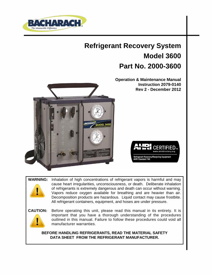
Refrigerant Recovery System
Model 3600 Part No. 2000-3600
Operation & Maintenance Manual
Instruction 2079-0140 Rev 2 - December 2012
WARNING: Inhalation of high concentrations of refrigerant vapors is harmful and may cause heart irregularities, unconsciousness, or death. Deliberate inhalation of refrigerants is extremely dangerous and death can occur without warning. Vapors reduce oxygen available for breathing and are heavier than air. Decomposition products are hazardous. Liquid contact may cause frostbite. All refrigerant containers, equipment, and hoses are under pressure.
CAUTION: Before operating this unit, please read this manual in its entirety. It is
important that you have a thorough understanding of the procedures outlined in this manual. Failure to follow these procedures could void all manufacturer warranties.
BEFORE HANDLING REFRIGERANTS, READ THE MATERIAL SAFETY
DATA SHEET FROM THE REFRIGERANT MANUFACTURER.
Refrigerant Recovery System Model 3600
2
Table of Contents
CHAPTER 1: INTRODUCTION ................................................................................................................................. 3
1.1. OVERVIEW ........................................................................................................................................................ 3 1.2. SPECIFICATIONS .................................................................................................................................................. 3 1.3. FEATURES ......................................................................................................................................................... 4
CHAPTER 2: SAFETY ............................................................................................................................................... 5
2.1. GENERAL SAFETY INSTRUCTIONS ............................................................................................................................ 5 2.2. OPERATIONAL SAFETY ......................................................................................................................................... 6
CHAPTER 3: FEATURES .......................................................................................................................................... 7
3.1. LOCATION AND DESCRIPTION OF UNIT FEATURES ...................................................................................................... 7 3.2. LED DISPLAY ..................................................................................................................................................... 8
CHAPTER 4: RECOVERY .......................................................................................................................................... 9
4.1. HELPFUL HINTS FOR RECOVERING R-410A .............................................................................................................. 9 4.2. VAPOR/LIQUID RECOVERY PROCEDURES ................................................................................................................. 9 4.3. VAPOR RECOVERY HOSE CONNECTION ................................................................................................................. 11 4.4. LIQUID PUSH-PULL RECOVERY GENERAL INFORMATION ........................................................................................... 12 4.5. LIQUID RECOVERY PROCEDURES .......................................................................................................................... 13 4.6. LIQUID PUSH-PULL HOSE CONNECTIONS ............................................................................................................... 14 4.7. PUMP DOWN OPERATIONS ................................................................................................................................ 15 4.8. DOT RECOVERY CYLINDER SAFETY ....................................................................................................................... 16
CHAPTER 5: TROUBLESHOOTING ......................................................................................................................... 17
CHAPTER 6: ELECTRICAL SCHEMATIC ................................................................................................................... 18
CHAPTER 7: REPLACEMENT PARTS ...................................................................................................................... 19
Model 3600 Refrigerant Recovery System
3
CHAPTER 1: INTRODUCTION
1.1. Overview Congratulations on your purchase of the Bacharach Model 3600 high performance oilless recovery system. Bacharach has worked hard to make the Model 3600 the highest performing, most portable and easiest to use recovery system on the market. We are committed to your complete satisfaction! Please note that Bacharach requires that a filter be used on the inlet hose coming from the system being serviced in order to protect the compressor from particulate. A standard filter or filter dryer is suggested. The compressor warranty will be voided if it is determined that a filter was not used during the operation of this equipment. WARNING: Before starting the 3600 recovery unit, you MUST OPEN the outlet port on the unit
and open the port to the recovery tank. Read the entire operating instruction manual before use. Failure to open the outlet port will cause permanent damage to the unit and void the warranty.
WARNING: You must use a DOT recovery cylinder approved for use with R-410A refrigerant.
This recovery system is equipped with a high-pressure shutoff switch set to turn the unit off at 550 psi. Using any other cylinder may cause the pressure in the recovery cylinder to exceed the cylinder’s pressure rating.
CAUTION: These instructions are for personnel trained and experienced in the handling of
refrigerants. Unqualified individuals should not attempt to operate this equipment. Failure to follow proper operating procedures may cause personal injury.
1.2. Specifications Category Description
Model Model 3600 Description Portable Commercial Oilless Recovery System Refrigerants R12, R-22, R-134a, R-500, R-502, R-410AHP/MP Blends Power Source 120V AC 60 Hz Wattage/Amperes 800 W / 8.0 A max Compressor ½ HP High Performance Oilless High Pressure Shutoff 550 psi Dimensions (H x W x D) 12.0" x 13" x 7.5" Weight 35 Lbs.
Refrigerant Recovery System Model 3600
4
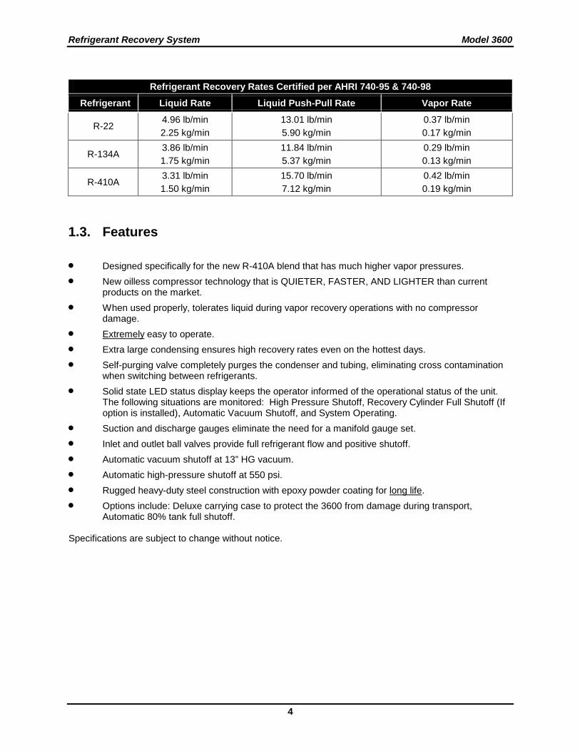
Refrigerant Recovery Rates Certified per AHRI 740-95 & 740-98
Refrigerant Liquid Rate Liquid Push-Pull Rate Vapor Rate
R-22 4.96 lb/min 2.25 kg/min
13.01 lb/min 5.90 kg/min
0.37 lb/min 0.17 kg/min
R-134A 3.86 lb/min 1.75 kg/min
11.84 lb/min 5.37 kg/min
0.29 lb/min 0.13 kg/min
R-410A 3.31 lb/min 1.50 kg/min
15.70 lb/min 7.12 kg/min
0.42 lb/min 0.19 kg/min
1.3. Features • Designed specifically for the new R-410A blend that has much higher vapor pressures. • New oilless compressor technology that is QUIETER, FASTER, AND LIGHTER than current
products on the market. • When used properly, tolerates liquid during vapor recovery operations with no compressor
damage. • Extremely easy to operate. • Extra large condensing ensures high recovery rates even on the hottest days. • Self-purging valve completely purges the condenser and tubing, eliminating cross contamination
when switching between refrigerants. • Solid state LED status display keeps the operator informed of the operational status of the unit.
The following situations are monitored: High Pressure Shutoff, Recovery Cylinder Full Shutoff (If option is installed), Automatic Vacuum Shutoff, and System Operating.
• Suction and discharge gauges eliminate the need for a manifold gauge set. • Inlet and outlet ball valves provide full refrigerant flow and positive shutoff. • Automatic vacuum shutoff at 13” HG vacuum. • Automatic high-pressure shutoff at 550 psi. • Rugged heavy-duty steel construction with epoxy powder coating for long life. • Options include: Deluxe carrying case to protect the 3600 from damage during transport,
Automatic 80% tank full shutoff. Specifications are subject to change without notice.
Model 3600 Refrigerant Recovery System
5
CHAPTER 2: SAFETY
2.1. General Safety Instructions 1. KNOW YOUR EQUIPMENT
Read and understand the operation manual and labels affixed to the unit. Learn its application and limitations as well as the specific potential hazards of your equipment.
2. GROUND ALL EQUIPMENT
This unit is equipped with an approved three pronged grounded power cord and plug. The green wire is the ground wire and should never be connected to a live terminal.
3. USE THE PROPER EXTENSION CORD
Use the following guide for choosing the proper extension cord:
16 gauge cord- maximum length 25 feet 14 gauge cord- maximum length 50 feet 12 gauge cord- maximum length 100 feet
4. AVOID DANGEROUS ENVIRONMENTS
Do not use this unit in damp or wet locations or expose it to rain. Secure unit when working above floor level. This equipment should be used in a location with mechanical ventilation that provides at least four air changes per hour or the equipment should be located at least 18 inches above the floor. This equipment should not be used in the vicinity of spilled or open containers of flammable materials.
5. DISCONNECT UNIT BEFORE SERVICING
Electrical shock hazard may be present when the unit is disassembled.
6. AVOID ACCIDENTAL STARTING
Make sure the system switch is in the OFF position before connecting electrical devices.
7. REPAIR DAMAGED PARTS
Do not operate the unit with a defective part. Repair unit to proper operating conditions.
8. USE RECOMMENDED ACCESSORIES
Follow the instructions that accompany all accessories. Improper use of accessories may damage the equipment or create a hazard.
9. USE CAUTION WHEN CONNECTING OR DISCONNECTING HOSES
Improper usage may result in refrigerant burns (frostbite). If a significant refrigerant leak occurs, proceed immediately to a well ventilated area.
10. USE THE PROPER RECOVERY CYLINDER RATED FOR USE WITH R-410A WARNING: You must use the proper DOT approved recovery cylinder with the Model 3600. This
recovery system is equipped with a high-pressure shutoff switch set to turn the unit off at 550 psi. Using any other cylinder may cause the pressure in the recovery cylinder to exceed the cylinder’s pressure rating.

Refrigerant Recovery System Model 3600
6
2.2. Operational Safety WARNING: Inhalation of high concentrations of refrigerant vapors is harmful and may cause heart
irregularities, unconsciousness, or death. Deliberate inhalation of refrigerants is extremely dangerous and death may occur without warning. Vapor reduces oxygen available for breathing and is heavier than air. Decomposition products are hazardous. Liquid contact can cause frostbite. All refrigerant containers, equipment and hoses are under high pressure.
• Avoid breathing high concentrations of vapors. • Use with sufficient ventilation to keep operator exposure below recommended limits, especially in
enclosed and low lying areas. • Avoid contact of liquid with eyes and prolonged skin exposure. • Wear safety goggles and protective gloves. • Do not apply open flame or heat unit above 125°F. • Do not allow refrigerants to contact open flame. Decomposition will occur.
FIRST AID: If high concentrations of refrigerant vapors are inhaled, immediately remove person(s) to
fresh air. Keep calm. If not breathing, give artificial respiration. If breathing is difficult, give oxygen. Call a doctor. Do not give epinephrine or similar drugs.
EYE: In case of liquid contact, immediately flush eye with water.
Seek medical attention. SKIN: Flush with water. Treat for frostbite by gently warming the affected area.
CAUTION: All refrigerant hoses, recovery tanks, refrigerant lines, the unit, and other vessels containing refrigerants should be handled at all times as if under high pressure.
Model 3600 Refrigerant Recovery System
7
CHAPTER 3: FEATURES
3.1. Location and Description of Unit Features
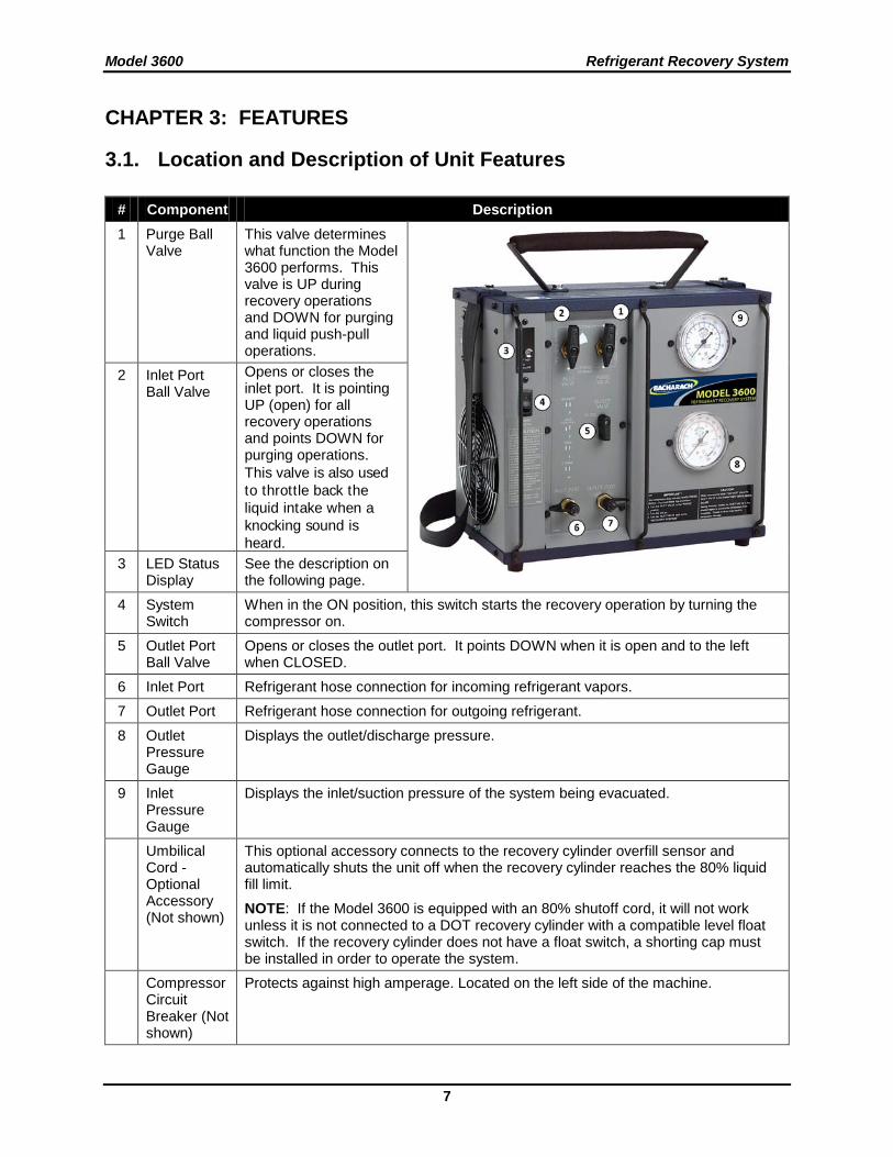
# Component Description 1 Purge Ball
Valve This valve determines what function the Model 3600 performs. This valve is UP during recovery operations and DOWN for purging and liquid push-pull operations.
2 Inlet Port Ball Valve
Opens or closes the inlet port. It is pointing UP (open) for all recovery operations and points DOWN for purging operations. This valve is also used to throttle back the liquid intake when a knocking sound is heard.
3 LED Status Display
See the description on the following page.
4 System Switch
When in the ON position, this switch starts the recovery operation by turning the compressor on.
5 Outlet Port Ball Valve
Opens or closes the outlet port. It points DOWN when it is open and to the left when CLOSED.
6 Inlet Port Refrigerant hose connection for incoming refrigerant vapors.
7 Outlet Port Refrigerant hose connection for outgoing refrigerant.
8 Outlet Pressure Gauge
Displays the outlet/discharge pressure.
9 Inlet Pressure Gauge
Displays the inlet/suction pressure of the system being evacuated.
Umbilical Cord - Optional Accessory (Not shown)
This optional accessory connects to the recovery cylinder overfill sensor and automatically shuts the unit off when the recovery cylinder reaches the 80% liquid fill limit. NOTE: If the Model 3600 is equipped with an 80% shutoff cord, it will not work unless it is not connected to a DOT recovery cylinder with a compatible level float switch. If the recovery cylinder does not have a float switch, a shorting cap must be installed in order to operate the system.
Compressor Circuit Breaker (Not shown)
Protects against high amperage. Located on the left side of the machine.
Refrigerant Recovery System Model 3600
8
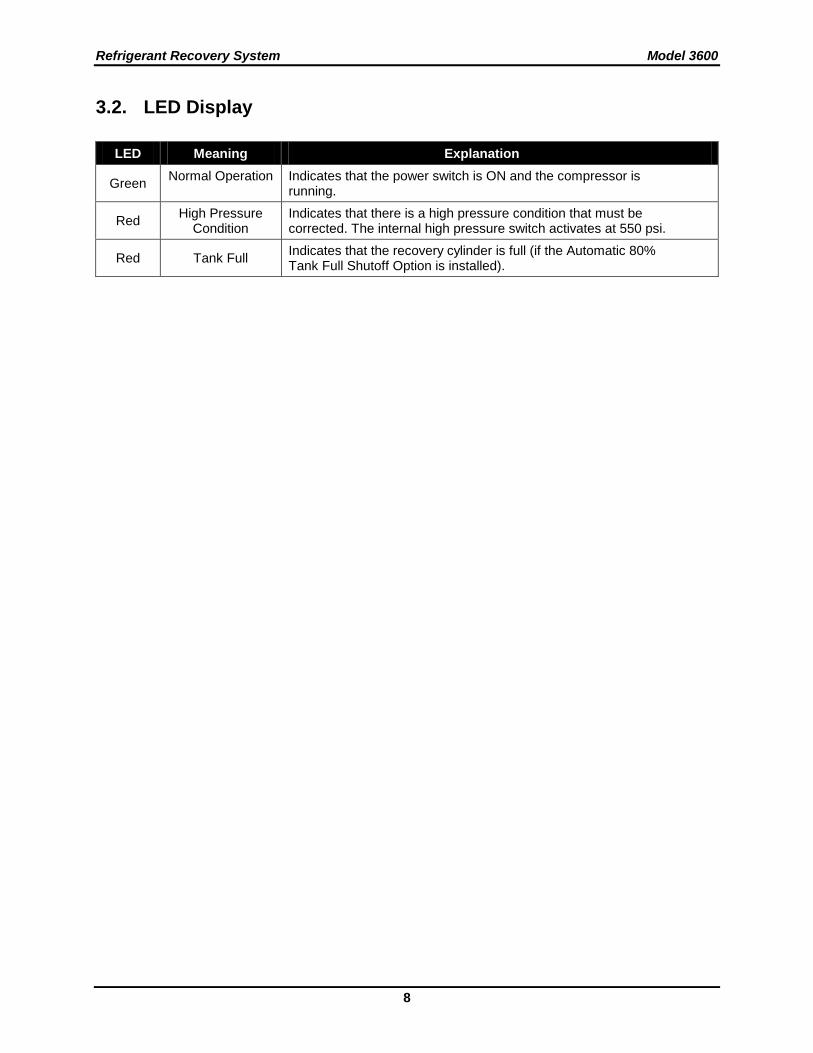
3.2. LED Display
LED Meaning Explanation
Green Normal Operation Indicates that the power switch is ON and the compressor is running.
Red High Pressure Condition
Indicates that there is a high pressure condition that must be corrected. The internal high pressure switch activates at 550 psi.
Red Tank Full Indicates that the recovery cylinder is full (if the Automatic 80% Tank Full Shutoff Option is installed).
Model 3600 Refrigerant Recovery System
9
CHAPTER 4: RECOVERY
4.1. Helpful Hints for Recovering R-410A R-410A has been designated by the EPA as a “very-high-pressure” refrigerant. Because of its higher vapor pressure, recovering R-410A has some unique challenges. The higher vapor pressure requires more work from the compressor, resulting in higher temperatures and increased wear on moving compressor parts. In order to reduce the affects of these conditions, Bacharach recommends the following:
• Whenever possible, cool your recovery tank with ice or water. This keeps the compressor discharge pressures lower, which will result in faster recovery rates and longer compressor life.
• Avoid recovering large amounts of R-410A at one time. Allow the recovery unit and cylinder to cool before starting the next recovery job.
• Always purge the machine completely when switching from R410a and back to prevent cross contamination.
Following these simple hints will improve both recovery performance and compressor life.
4.2. Vapor/Liquid Recovery Procedures Step Description
1 Turn off all electrical or mechanical power to the refrigerant device to be evacuated.
2 Make proper hose connections: Connect refrigerant hoses to recovery cylinder, the unit, and A/C system as shown in Figure 1. NOTE: You must use an external filter drier in the suction line in order to meet the conditions of the unit warranty. Caution: If the 80% shutoff cord is not used, a scale must be used to monitor the refrigerant level in the recovery cylinder. NOTE: Although the 3600 was designed to handle liquid slugging, pumping large amounts of liquid over extended periods of time will reduce the life of the compressor. If large amounts of liquid are present, it is recommended that you use the liquid push - pull method of recovery prior to vapor recovery operations. (See Figures 3 & 4).
3 Place the inlet and purge ball valves in the “CLOSED” position and the outlet valve is in the “OPEN” position. Open the DOT recovery tank liquid valve. (See Figure 2).
4 Turn the system switch to the “ON” position. The LED status display will be green.
5 Regulate the inlet port ball valve when liquid refrigerant is present. WARNING: A “knocking” sound coming from the compressor indicates too much liquid is
entering the compressor. The inlet ball valve must be regulated as shown in the shaded region until this knocking sound stops, otherwise compressor damage could occur. Pumping liquid when the compressor is knocking will damage the compressor and will reduce the compressor life and will void the compressor warranty.
Refrigerant Recovery System Model 3600
10
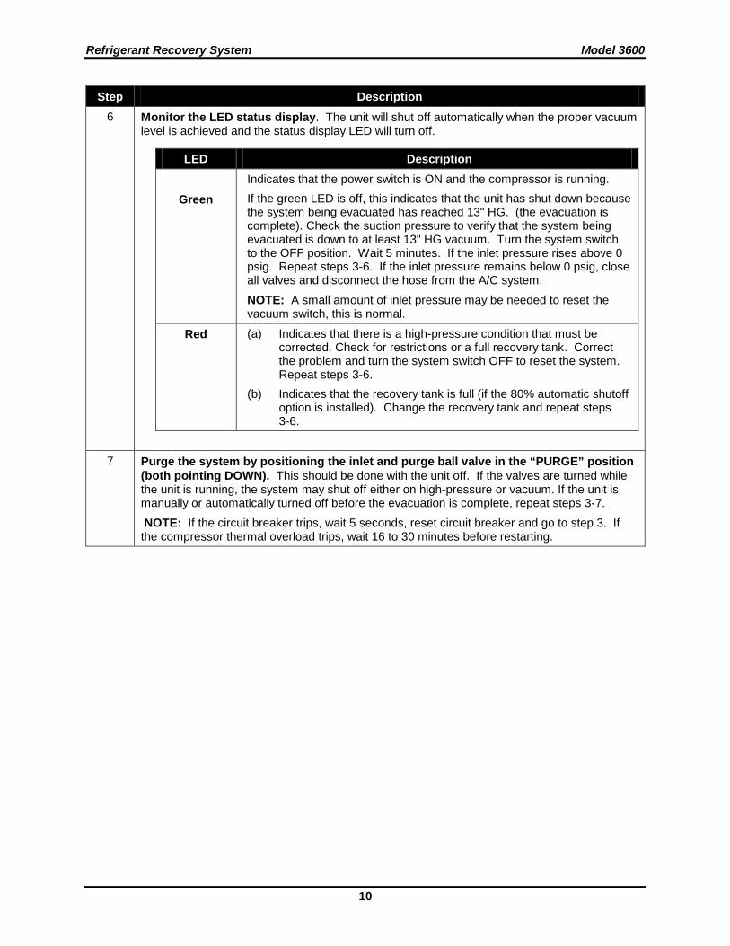
Step Description 6 Monitor the LED status display. The unit will shut off automatically when the proper vacuum
level is achieved and the status display LED will turn off.
LED Description
Green
Indicates that the power switch is ON and the compressor is running. If the green LED is off, this indicates that the unit has shut down because the system being evacuated has reached 13" HG. (the evacuation is complete). Check the suction pressure to verify that the system being evacuated is down to at least 13" HG vacuum. Turn the system switch to the OFF position. Wait 5 minutes. If the inlet pressure rises above 0 psig. Repeat steps 3-6. If the inlet pressure remains below 0 psig, close all valves and disconnect the hose from the A/C system. NOTE: A small amount of inlet pressure may be needed to reset the vacuum switch, this is normal.
Red (a) Indicates that there is a high-pressure condition that must be corrected. Check for restrictions or a full recovery tank. Correct the problem and turn the system switch OFF to reset the system. Repeat steps 3-6.
(b) Indicates that the recovery tank is full (if the 80% automatic shutoff option is installed). Change the recovery tank and repeat steps 3-6.
7 Purge the system by positioning the inlet and purge ball valve in the “PURGE” position (both pointing DOWN). This should be done with the unit off. If the valves are turned while the unit is running, the system may shut off either on high-pressure or vacuum. If the unit is manually or automatically turned off before the evacuation is complete, repeat steps 3-7. NOTE: If the circuit breaker trips, wait 5 seconds, reset circuit breaker and go to step 3. If the compressor thermal overload trips, wait 16 to 30 minutes before restarting.
Model 3600 Refrigerant Recovery System
11
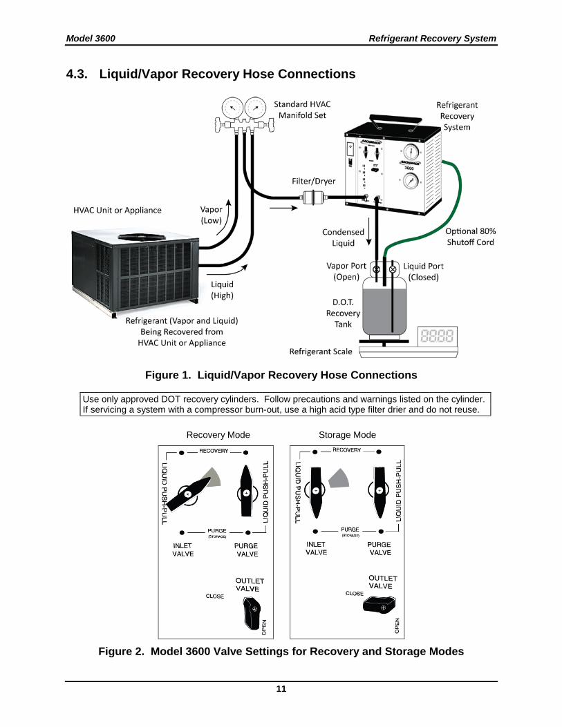
4.3. Liquid/Vapor Recovery Hose Connections
Figure 1. Liquid/Vapor Recovery Hose Connections
Use only approved DOT recovery cylinders. Follow precautions and warnings listed on the cylinder. If servicing a system with a compressor burn-out, use a high acid type filter drier and do not reuse.
Recovery Mode Storage Mode
Figure 2. Model 3600 Valve Settings for Recovery and Storage Modes
Refrigerant Recovery System Model 3600
12
4.4. Liquid Push-Pull Recovery General Information Attention: Before attempting the following liquid push-pull recovery operations, please review this page.
It may not be possible to recover liquid refrigerant from some types of refrigeration equipment.
A scale or liquid sight glass can be used to determine when all the liquid is recovered. The unit will not pull a vacuum using the push-pull liquid recovery operation. To finish the recovery operation, you must proceed to vapor recovery operations.
Guidelines
If any of these conditions are present in the system being evacuated, liquid push-pull operations may not be practical and vapor recovery operations should be performed.
• The equipment contains less than 15 lbs. of refrigerant.
• The equipment is a heat pump or other system with refrigerant flow that would prevent you from isolating the liquid.
• Equipment has an accumulator between the service ports used in the liquid recovery process.
• Liquid refrigerant migration has occurred and the location of the liquid is unknown.
• The refrigerant tubing design on the equipment does not allow for a solid column of liquid refrigerant to be formed.
Direct Liquid Recovery Operations
All compressors are designed to compress gases. Normally compressors are not capable of pumping non-compressible fluids such as liquid refrigerant, however, the 3600 has been designed with a special head and valves that enable it to handle liquid directly. This feature makes the 3600 easier to use by minimizing the need to monitor incoming refrigerant vapors and reduces compressor failures due to liquid slugging.
It is important to remember that the 3600 is a compressor and not a liquid pump. When large amounts of liquid are present, the liquid push-pull method of recovery should be used. Using the 3600 to pump large amounts of liquid refrigerant over a long period of time will reduce the compressor life.
WARNING: A “Knocking” sound coming from the compressor indicates too much liquid is entering the compressor. The inlet ball valve must be regulated as shown in the shaded region until this knocking sound stops, otherwise compressor damage could occur. Pumping liquid when the compressor is knocking will damage the compressor and will reduce the compressor life. This will void the compressor warranty.
A sudden slug of liquid into the compressor may cause a sudden spike in pressure and cause the high-pressure safety shutoff switch to shut the compressor off. If this happens, you must clear the liquid from the compressor before you can restart the compressor. To prevent this from happening, always open the inlet valve slowly when starting a recovery job. Opening the inlet valve quickly could allow a slug of liquid to enter the cylinder and cause the high-pressure switch to shut the system down.

Model 3600 Refrigerant Recovery System
13
4.5. Liquid Push Pull Recovery Procedures Liquid push-pull operations are performed by using hot compressor gas to push liquid refrigerant out of a system. The purge valve accomplishes this by re-directing the hot compressor gas around the condenser. See the diagram on top of the unit for hose connections.
Step Description 1 Turn off all electrical or mechanical power to the refrigerant device to be evacuated. 2 Make proper hose connections. Connect the discharge hose from the outlet port to the low-
pressure side of the system you are servicing. Connect a hose between the liquid port (receiver or condenser) on the system being serviced and the liquid valve on the DOT recovery tank. Connect the inlet hose from the DOT recovery tank vapor valve and the unit’s inlet port. See Figure 3 for hose connection schematic. NOTE: You must use an external filter drier in the suction line in order to meet the conditions of the unit warranty. Caution: If the 80% shutoff cord is not used, a scale must be used to monitor the refrigerant level in the recovery cylinder.
3 Place the inlet and purge valves in the “LIQUID PUSH-PULL” position. This will allow hot compressor gas to bypass the condenser. OPEN the liquid and vapor valves on the tank, (See Figure 4)
4 Open the outlet ball valve and the DOT recovery tank vapor and liquid valves on the DOT recovery tank.
5 Turn the system switch to the “ON” position. When all liquid refrigerant is recovered, turn the system switch to the “OFF” position. NOTE: Liquid push-pull operations do not pull a vacuum on a system. You must perform a vapor recovery operation in order to pull the system down to the required vacuum level.
6 Monitor the LED status display.
LED Description
Green SYSTEM ON: The “SYSTEM ON” indicator should be ON during normal operations.
No LED
EVACUATION COMPLETE: Indicates that the unit has shut down because the system being evacuated has reached 13" HG. (the evacuation is complete). During liquid push-pull operations the system will not be pulled into a vacuum. NOTE: A small amount of inlet pressure might be needed to reset the vacuum switch, this is normal.
Red
HIGH PRESSURE: Indicates that there is a high pressure condition that must be corrected. Check for restrictions or a full recovery cylinder. Correct problem and turn system switch to the OFF position. Repeat steps 3-6. TANK FULL: Indicates that the recovery cylinder is full (if the 80% Automatic Tank Full Shutoff Option is installed). Change the recovery cylinder and repeat steps 3-6.
7 Turn the system switch to the OFF position when all liquid is recovered. The liquid recovery operation is complete when the scale or optional sight glass indicates no liquid is being transferred to the recovery cylinder. NOTE: The unit must be manually shut off during all liquid recovery operations.
8 Proceed to vapor recovery operations to complete the recovery operation. If the unit is manually or automatically turned off before the liquid recovery is complete, repeat steps 3-8. NOTE: If the circuit breaker trips, wait 10 seconds, reset circuit breaker and go to step 2. If the compressor thermal overload trips, wait 16 to 30 minutes before restarting.
Refrigerant Recovery System Model 3600
14
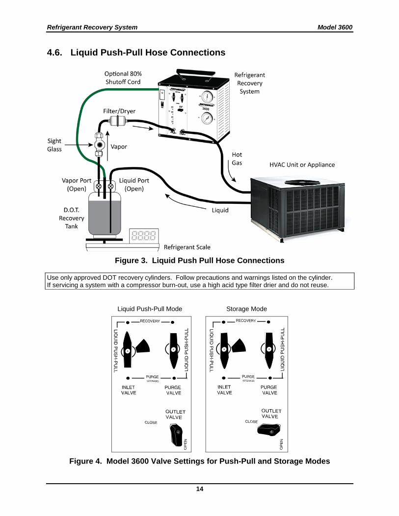
4.6. Liquid Push-Pull Hose Connections
Figure 3. Liquid Push Pull Hose Connections
Use only approved DOT recovery cylinders. Follow precautions and warnings listed on the cylinder. If servicing a system with a compressor burn-out, use a high acid type filter drier and do not reuse.
Liquid Push-Pull Mode Storage Mode
Figure 4. Model 3600 Valve Settings for Push-Pull and Storage Modes
Model 3600 Refrigerant Recovery System
15
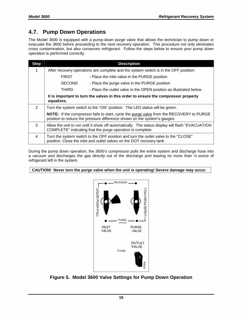
4.7. Pump Down Operations The Model 3600 is equipped with a pump-down purge valve that allows the technician to pump down or evacuate the 3600 before proceeding to the next recovery operation. This procedure not only eliminates cross contamination, but also conserves refrigerant. Follow the steps below to ensure your pump down operation is performed correctly.
Step Description 1 After recovery operations are complete and the system switch is in the OFF position:
FIRST - Place the inlet valve in the PURGE position SECOND - Place the purge valve in the PURGE position THIRD - Place the outlet valve in the OPEN position as illustrated below. It is important to turn the valves in this order to ensure the compressor properly equalizes.
2 Turn the system switch to the “ON” position. The LED status will be green. NOTE: If the compressor fails to start, cycle the purge valve from the RECOVERY to PURGE position to reduce the pressure difference shown on the system’s gauges.
3 Allow the unit to run until it shuts off automatically. The status display will flash “EVACUATION COMPLETE” indicating that the purge operation is complete.
4 Turn the system switch to the OFF position and turn the outlet valve to the “CLOSE” position. Close the inlet and outlet valves on the DOT recovery tank.
During the pump down operation, the 3600’s compressor pulls the entire system and discharge hose into a vacuum and discharges the gas directly out of the discharge port leaving no more than ¼ ounce of refrigerant left in the system.
CAUTION! Never turn the purge valve when the unit is operating! Severe damage may occur.
Figure 5. Model 3600 Valve Settings for Pump Down Operation
Refrigerant Recovery System Model 3600
16
4.8. DOT Recovery Cylinder Safety An optional 80% recovery cylinder shutoff cord is available with the Model 3600. If equipped, this cord connects to the recovery cylinder float switch and will automatically shut the Model 3600 off when the recovery cylinder becomes 80% full. When the Model 3600 is equipped with the 80% shutoff cord, Bacharach recommends that you use this cord for added safety. If the Model 3600 is not equipped with an 80% shutoff cord, or, if you are using a recovery cylinder that does not have a float switch, then you must use a scale and the guidelines below to prevent overfilling of the cylinder. NOTE: THE SHORTING CAP MUST BE USED IN ORDER TO OPERATE THE MODEL 3600 WITHOUT THE 80% SHUTOFF CORD ATTACHED TO THE RECOVERY CYLINDER. Bacharach uses and recommends the Air Conditioning & Refrigeration Institute's (AHRI) guideline K for the safe filling and handling of used refrigerant. This Publication is available from ARI. WARNING: You must use a DOT recovery cylinder approved for use with R-410A refrigerant.
This recovery system is equipped with a high-pressure shutoff switch set to turn the unit off at 550 psi. Using any other cylinder may cause the pressure in the recovery cylinder to exceed the cylinder’s pressure rating.
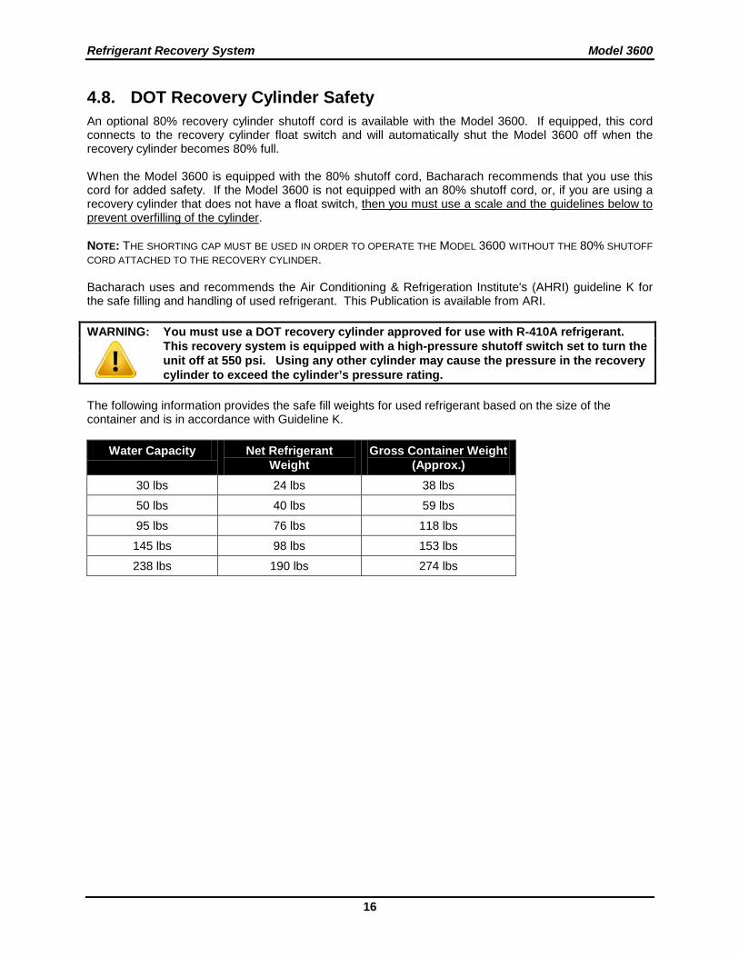
The following information provides the safe fill weights for used refrigerant based on the size of the container and is in accordance with Guideline K.
Water Capacity Net Refrigerant Weight
Gross Container Weight (Approx.)
30 lbs 24 lbs 38 lbs
50 lbs 40 lbs 59 lbs
95 lbs 76 lbs 118 lbs
145 lbs 98 lbs 153 lbs
238 lbs 190 lbs 274 lbs
Model 3600 Refrigerant Recovery System
17
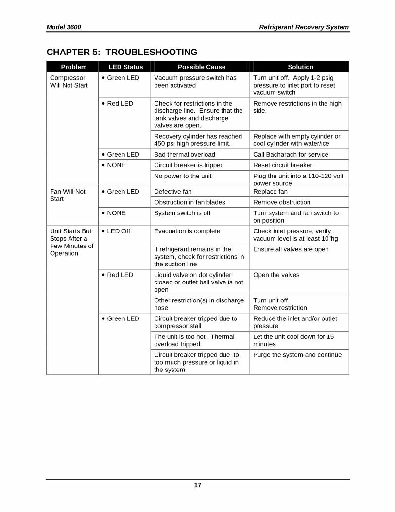
CHAPTER 5: TROUBLESHOOTING Problem LED Status Possible Cause Solution
Compressor Will Not Start
• Green LED Vacuum pressure switch has been activated
Turn unit off. Apply 1-2 psig pressure to inlet port to reset vacuum switch
• Red LED Check for restrictions in the discharge line. Ensure that the tank valves and discharge valves are open.
Remove restrictions in the high side.
Recovery cylinder has reached 450 psi high pressure limit.
Replace with empty cylinder or cool cylinder with water/ice
• Green LED Bad thermal overload Call Bacharach for service
• NONE Circuit breaker is tripped Reset circuit breaker
No power to the unit Plug the unit into a 110-120 volt power source
Fan Will Not Start
• Green LED Defective fan Replace fan
Obstruction in fan blades Remove obstruction
• NONE System switch is off Turn system and fan switch to on position
Unit Starts But Stops After a Few Minutes of Operation
• LED Off Evacuation is complete Check inlet pressure, verify vacuum level is at least 10"hg
If refrigerant remains in the system, check for restrictions in the suction line
Ensure all valves are open
• Red LED Liquid valve on dot cylinder closed or outlet ball valve is not open
Open the valves
Other restriction(s) in discharge hose
Turn unit off. Remove restriction
• Green LED Circuit breaker tripped due to compressor stall
Reduce the inlet and/or outlet pressure
The unit is too hot. Thermal overload tripped
Let the unit cool down for 15 minutes
Circuit breaker tripped due to too much pressure or liquid in the system
Purge the system and continue
Refrigerant Recovery System Model 3600
18
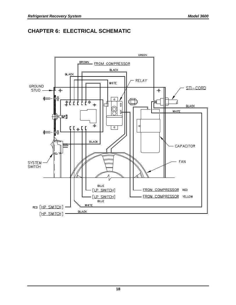
CHAPTER 6: ELECTRICAL SCHEMATIC
Model 3600 Refrigerant Recovery System
19
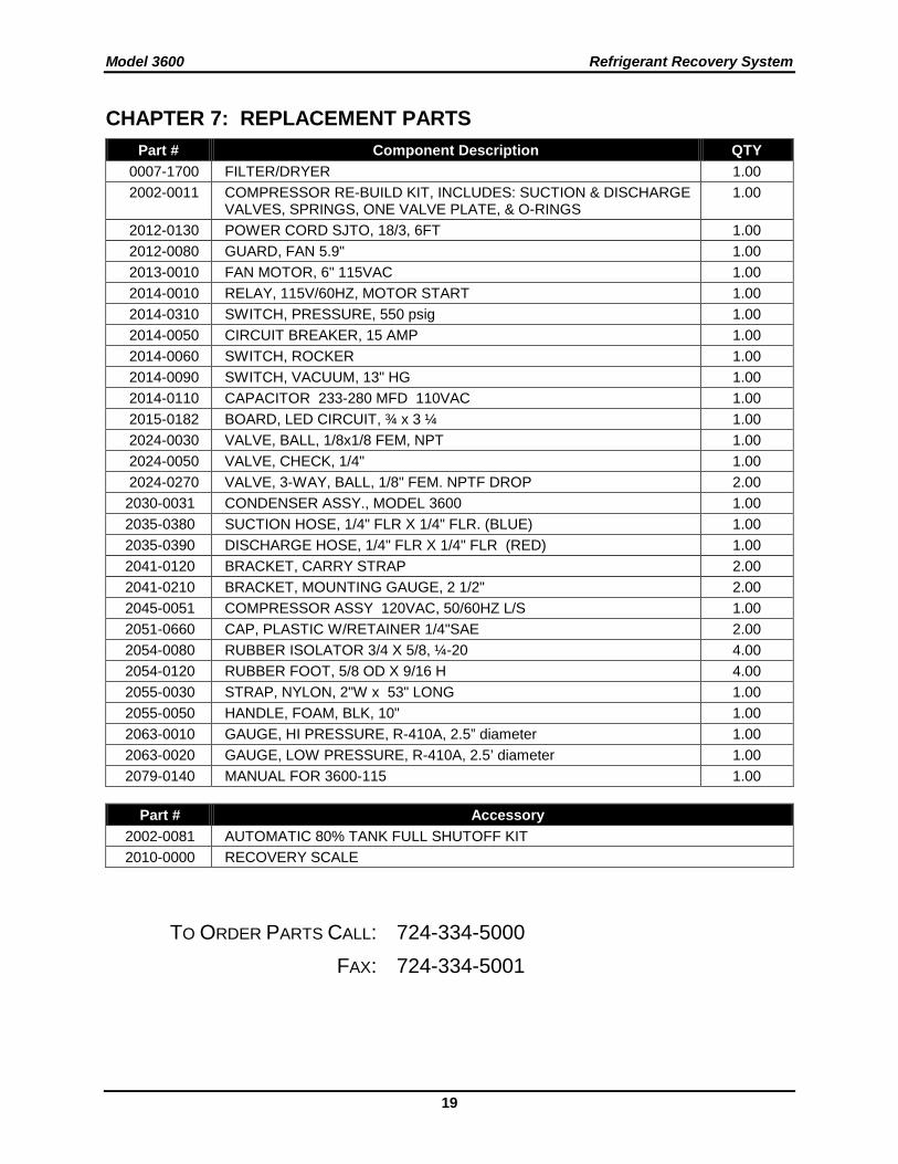
CHAPTER 7: REPLACEMENT PARTS Part # Component Description QTY
0007-1700 FILTER/DRYER 1.00 2002-0011 COMPRESSOR RE-BUILD KIT, INCLUDES: SUCTION & DISCHARGE
VALVES, SPRINGS, ONE VALVE PLATE, & O-RINGS 1.00
2012-0130 POWER CORD SJTO, 18/3, 6FT 1.00 2012-0080 GUARD, FAN 5.9" 1.00 2013-0010 FAN MOTOR, 6" 115VAC 1.00 2014-0010 RELAY, 115V/60HZ, MOTOR START 1.00 2014-0310 SWITCH, PRESSURE, 550 psig 1.00 2014-0050 CIRCUIT BREAKER, 15 AMP 1.00 2014-0060 SWITCH, ROCKER 1.00 2014-0090 SWITCH, VACUUM, 13" HG 1.00 2014-0110 CAPACITOR 233-280 MFD 110VAC 1.00 2015-0182 BOARD, LED CIRCUIT, ¾ x 3 ¼ 1.00 2024-0030 VALVE, BALL, 1/8x1/8 FEM, NPT 1.00 2024-0050 VALVE, CHECK, 1/4" 1.00 2024-0270 VALVE, 3-WAY, BALL, 1/8" FEM. NPTF DROP 2.00 2030-0031 CONDENSER ASSY., MODEL 3600 1.00 2035-0380 SUCTION HOSE, 1/4" FLR X 1/4" FLR. (BLUE) 1.00 2035-0390 DISCHARGE HOSE, 1/4" FLR X 1/4" FLR (RED) 1.00 2041-0120 BRACKET, CARRY STRAP 2.00 2041-0210 BRACKET, MOUNTING GAUGE, 2 1/2" 2.00 2045-0051 COMPRESSOR ASSY 120VAC, 50/60HZ L/S 1.00 2051-0660 CAP, PLASTIC W/RETAINER 1/4"SAE 2.00 2054-0080 RUBBER ISOLATOR 3/4 X 5/8, ¼-20 4.00 2054-0120 RUBBER FOOT, 5/8 OD X 9/16 H 4.00 2055-0030 STRAP, NYLON, 2"W x 53" LONG 1.00 2055-0050 HANDLE, FOAM, BLK, 10" 1.00 2063-0010 GAUGE, HI PRESSURE, R-410A, 2.5” diameter 1.00 2063-0020 GAUGE, LOW PRESSURE, R-410A, 2.5’ diameter 1.00 2079-0140 MANUAL FOR 3600-115 1.00
Part # Accessory
2002-0081 AUTOMATIC 80% TANK FULL SHUTOFF KIT 2010-0000 RECOVERY SCALE
TO ORDER PARTS CALL: 724-334-5000 FAX: 724-334-5001
Refrigerant Recovery System Model 3600
20
World Headquarters
621 Hunt Valley Circle, New Kensington, PA 15068 Ph: 724-334-5000 • Fax: 724-334-5001 • Toll Free: 1-800-736-4666
Web site: www.MyBacharach.com • E-mail: [email protected]
PRINTED IN U.S.A. ® REGISTERED TRADEMARK