refrigerant transition under f-gas regulation 517/2014 · refrigerant transition ... a period of 5...
TRANSCRIPT
CO2 e
quiv
alen
t (M
M to
nnes
)
100%
-7%
-37%
-55%
-69%-76% -79%
160
180
140
120
100
80
60
40
20
0
20152016
20172018
20192020
20212022
20232024
20252026
20272028
20292030
Refrigerant Transition Under F-gas Regulation 517/2014Practical options towards future-proof HVACR systems
IntroductionEU legislation is irreversibly driving our markets towards higher efficiency and lower greenhouse gas emissions. This is the result of a wider effort that Emerson Climate Technologies is actively involved in, i.e. the EU 2050 roadmap towards a low carbon economy.
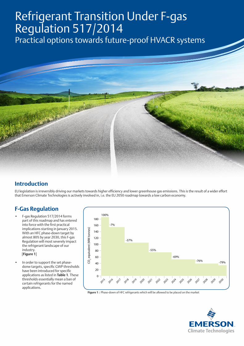
F-Gas Regulation• F-gas Regulation 517/2014 forms
part of this roadmap and has entered into force with the first practical implications starting in January 2015. With an HFC phase-down target by almost 80% by year 2030, this F-gas Regulation will most severely impact the refrigerant landscape of our industry.
[Figure 1]
• In order to support the set phase-donw targets, specific GWP thresholds have been introduced for specific applications as listed in Table 1. These thresholds essentially mean a ban of certain refrigerants for the named applications.
Figure 1 : Phase-down of HFC refrigerants which will be allowed to be placed on the market

Refrigerant Alternatives• The safest way for any organization in any market/application to handle this situation is to convert their business activity to refrigerants with
a GWP well below 10. From today’s perspective, such refrigerants may be considered future-proof, i.e. they are likely to stay on the market for the foreseeable future.
• In practice, life-cycle considerations, such as age of an installation, available investment budget, as well as application specific requirements may limit our ability to move fast to such future-proof refrigerants. To account for this, the market also requires intermediate refrigerants, i.e. refrigerants that may not be future-proof, but still allow for a significant reduction in GWP. In some applications, there is no practically useable alternative available yet so that the existing refrigerants have to be used in the foreseeable future. In some heating and cooling market segments, it is questionable if future-proof refrigerants with GWP < 10 will ever come to the market. In these segments intermediate refrigerants may turn into long-term solutions.
• For this reason the modeling of overall average GWP consumption becomes important. Industry segments where future-proof refrigerant choices exist today need to compensate for those that do not have alternatives readily available in order to achieve the overall reduction target.
• It is practical to look at refrigerant choices in categories and consider only those refrigerants individually that stand a high chance to remain on the market long-term, i.e. future-proof refrigerants.
• Such categories are summarized in the table below.
Refrigerant Category Designation Examples GWP Range Ready-to-use Natural
Low GWP HFC alternatives HFC A1 R407A/F, R134a 1400 to 2500 today
Intermediate refrigerantsHFO A1 Blends R449A, R450A 400 to 1500 today
HFO A2L Blends, R32 R447A, R454B, R32 150…700 > 2016
Future-proof refrigerants
HFO R1234yf, R1234ze 4…6 > 2016
A3 R290 (Propane) 3 today ✔A1 R744 (CO2) 1 today ✔
Table 1
Table 2
• From the above it is obvious that the most widespread refrigerant in stationary refrigeration today, R404A, will gradually disappear from the market. This is through the stationary refrgieration equipment limit to GWP 2500 and the HFC service ban with virgin refrigerant as of January 2020.
• Both, phase-down and bans, will introduce significant changes to the HVACR industry, going well beyond the choice of refrigerant and including changes to system architectures and field practices.
• The ambitious phase-down plan set by the EU calls for a rapid transition from today’s refrigerants to new alternatives with lower global warming potential.
Service and Maintenance Ban GWP Timing
HFCs 2500 Jan. 2020
Placing on the Market (New Equipment) Bans GWP Timing
Refrigerators and freezers for commercial use (hermetically sealed systems) 2500 Jan. 2020
Refrigerators and freezers for commercial use (hermetically sealed systems) 150 Jan. 2022
Stationary refrigeration equipment (except equipment for temperatures below 50°C) 2500 Jan. 2020
Multipack centralized refrigeration systems for commercial use with a capacity of ≥ 40 kW (except in the primary refrigerant circuit of cascade systems, where flourinated greenhouse gases with a GWP of less than 1500 may be used)
150 Jan. 2022
Movable room air-conditioning appliances (hermetically sealed equipment which is movable between rooms by the end-user) 150 Jan. 2020
Single split air-conditioning systems containing < 3 kg 750 Jan. 2025
Refrigerant Replacement Guidance• Today in year 2016 the refrigerant market is already in transition. Refrigerant producers have launched replacement options for some of the
frequently used refrigerants while still developing solutions for others.• Table 3 summarizes frequently used refrigerants and available low GWP alternatives that are either fully available on the market today
(ready-to-use) or being discussed as potential replacement candidates. • Those candidates that are not labeled as “ready-to-use” may be available for field testing, but they cannot be considered as main-stream
replacements today for various reasons. These may include unavailability of final chemical composition and property data, unavailability of production series components for these refrigerants and other reasons.
• It must also be indicated that the list is not exhaustive. Various refrigerant manufacturers are designing blends very similar to the ones listed in Table 4
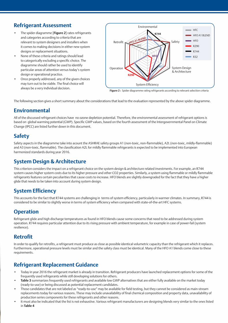
Refrigerant Assessment • The spider diagramme [Figure 2] rates refrigerants
and categories according to criteria that are relevant to system designers and installers when it comes to making decisions in either new system designs or replacement situations.
• None of these criteria and ratings should lead to categorically excluding a specific choice. The diagramme should rather be used to identify particular areas of attention versus today’s system design or operational practice.
• Once properly addressed, any of the given choices may turn out to be viable. The final choice will always be a very individual decision.
The following section gives a short summary about the considerations that lead to the evaluation represented by the above spider diagramme.
EnvironmentalAll of the discussed refrigerant choices have no ozone depletion potential. Therefore, the environmental assessment of refrigerant options is based on global warming potential (GWP). Specific GWP values, based on the fourth assessment of the Intergovernmental Panel on Climate Change (IPCC) are listed further down in this document.
SafetySafety aspects in the diagramme take into acount the ASHRAE safety groups A1 (non-toxic, non-flammable), A2L (non-toxic, mildly-flammable) and A3 (non-toxic, flammable). The classification A2L for mildly flammable refrigerants is expected to be implemented into European harmonized standards during year 2016.
System Design & ArchitectureThis criterion considers the impact on a refrigerant choice on the system design & architecture related investments. For example, an R744 system causes higher system costs due to its higher pressure and other CO2 properties. Similarly, a system using flammable or mildly flammable refrigerants features certain peculiarities that cause costs to increase. HFO blends are slightly downgraded for the fact that they have a higher glide that needs to be taken into account during system design.
System EfficiencyThis accounts for the fact that R744 systems are challenging in terms of system efficiency, particularly in warmer climates. In summary, R744 is considered to be similar to slightly worse in terms of system efficiency when compared with state-of-the-art HFC systems.
OperationRefrigerant glide and high discharge temperatures as found in HFO blends cause some concerns that need to be addressed during system operation. R744 requires particular attention due to its rising pressure with ambient temperature, for example in case of power-fail (system resilience).
RetrofitIn order to qualify for retrofits, a refrigerant must produce as close as possible identical volumetric capacity than the refrigerant which it replaces. Furthermore, operational pressure levels must be similar and the safety class must be identical. Many of the HFO A1 blends come close to these requirements.
Figure 2 : Spider diagramme rating refrigerants according to relevant selection criteria
Environmental
Safety
R744
HFC
HFO
R32
R290
HFO A1 BLEND
Retrofit
Operation System Design & Architecture
System Efficiency
HFC
HFO A1 BLEND
HFO
R290
R744
R32
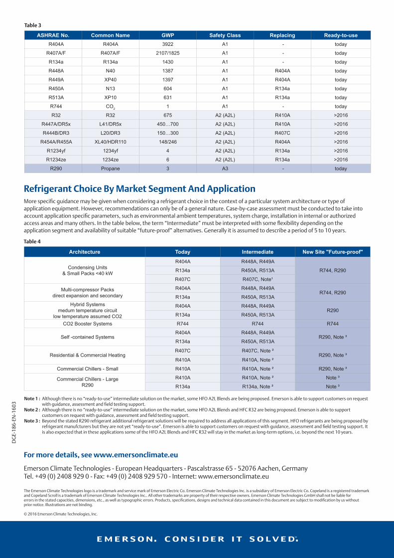
Refrigerant Choice By Market Segment And ApplicationMore specific guidance may be given when considering a refrigerant choice in the context of a particular system architecture or type of application equipment. However, recommendations can only be of a general nature. Case-by-case assessment must be conducted to take into account application specific parameters, such as environmental ambient temperatures, system charge, installation in internal or authorized access areas and many others. In the table below, the term “Intermediate” must be interpreted with some flexibility depending on the application segment and availability of suitable “future-proof” alternatives. Generally it is assumed to describe a period of 5 to 10 years.
Note 1 : Although there is no “ready-to-use” intermediate solution on the market, some HFO A2L Blends are being proposed. Emerson is able to support customers on request with guidance, assessment and field testing support.
Note 2 : Although there is no “ready-to-use” intermediate solution on the market, some HFO A2L Blends and HFC R32 are being proposed. Emerson is able to support customers on request with guidance, assessment and field testing support.
Note 3 : Beyond the stated R290 refrigerant additional refrigerant solutions will be required to address all applications of this segment. HFO refrigerants are being proposed by refrigerant manufcturers but they are not yet “ready-to-use”. Emerson is able to support customers on request with guidance, assessment and field testing support. It is also expected that in these applications some of the HFO A2L Blends and HFC R32 will stay in the market as long-term options, i.e. beyond the next 10 years.
DGE-18
6-EN
-160
3
The Emerson Climate Technologies logo is a trademark and service mark of Emerson Electric Co. Emerson Climate Technologies Inc. is a subsidiary of Emerson Electric Co. Copeland is a registered trademarkand Copeland Scroll is a trademark of Emerson Climate Technologies Inc.. All other trademarks are property of their respective owners. Emerson Climate Technologies GmbH shall not be liable forerrors in the stated capacities, dimensions, etc., as well as typographic errors. Products, specifications, designs and technical data contained in this document are subject to modification by us withoutprior notice. Illustrations are not binding.
© 2016 Emerson Climate Technologies, Inc.
For more details, see www.emersonclimate.eu
Emerson Climate Technologies - European Headquarters - Pascalstrasse 65 - 52076 Aachen, GermanyTel. +49 (0) 2408 929 0 - Fax: +49 (0) 2408 929 570 - Internet: www.emersonclimate.eu
ASHRAE No. Common Name GWP Safety Class Replacing Ready-to-useR404A R404A 3922 A1 - today
R407A/F R407A/F 2107/1825 A1 - today
R134a R134a 1430 A1 - today
R448A N40 1387 A1 R404A today
R449A XP40 1397 A1 R404A today
R450A N13 604 A1 R134a today
R513A XP10 631 A1 R134a today
R744 CO2 1 A1 - today
R32 R32 675 A2 (A2L) R410A >2016
R447A/DR5x L41/DR5x 450…700 A2 (A2L) R410A >2016
R444B/DR3 L20/DR3 150…300 A2 (A2L) R407C >2016
R454A/R455A XL40/HDR110 148/246 A2 (A2L) R404A >2016
R1234yf 1234yf 4 A2 (A2L) R134a >2016
R1234ze 1234ze 6 A2 (A2L) R134a >2016
R290 Propane 3 A3 - today
Architecture Today Intermediate New Site "Future-proof"
Condensing Units & Small Packs <40 kW
R404A R448A, R449A
R744, R290R134a R450A, R513A
R407C R407C, Note¹
Multi-compressor Packs direct expansion and secondary
R404A R448A, R449AR744, R290
R134a R450A, R513AHybrid Systems
medum temperature circuitlow temperature assumed CO2
R404A R448A, R449AR290
R134a R450A, R513A
CO2 Booster Systems R744 R744 R744
Self -contained SystemsR404A R448A, R449A
R290, Note ³R134a R450A, R513A
Residential & Commercial HeatingR407C R407C, Note ²
R290, Note ³R410A R410A, Note ²
Commercial Chillers - Small R410A R410A, Note ² R290, Note ³
Commercial Chillers - LargeR290
R410A R410A, Note ² Note ³
R134a R134a, Note ² Note ³
Table 3
Table 4