refupmu – power management · pdf filerefupmu provides the refulog monitoring portal...
TRANSCRIPT

REFUpmu – Power Management Unit
Operation Instructions
Version 08

BA_REFUpmu_V08_EN
Title REFUpmu – Power Management Unit
REFUpmu is a registered trademark of REFUsol GmbH
Documentation type Operating instructions
Documentation purpose This documentation describes how the power supply company can re-duce the power of a photovoltaic plant and how such a plant can be connected to the REFUlog monitoring portal via REFUpmu.
It provides information
connecting the REFUpmu to the ripple control receiver
connection of the REFUsol-inverter to the REFUlog monitoring portal via RS485
the specification of the cos φ as an analogue value
Publisher
REFUsol GmbH Uracher Straße 91 D-72555 Metzingen
www.refusol.com
Legal reservation
All details in this documentation have been compiled and tested with the greatest care. Errors of deviations can nevertheless not entirely be ex-cluded due to technical progress. No liability is assumed in terms of completeness. The version which is currently available can be downloaded at www.refusol.com .
Copyright
The details contained in this documentation are the property of REFUsol GmbH. The sale or publication of this documentation, including in ex-cerpts, cna only be undertaken with the written approval of REFUsol GmbH.
Warenzeichen REFUpmu® is a registered trade mark of REFUsol GmbH.
Version code Remarks
BA_REFUpmu _V08_EN 2012/12/MR
2

BA_REFUpmu_V08_EN
Table of Contents
1. Safety-Related Guidelines for REFUpmu ................................................................................ 5 1.1 Protection against Touching Electrical Parts .................................................................. 5 1.2 Disposal .......................................................................................................................... 5 1.3 General Information ........................................................................................................ 6
2. REFUpmu Power Management Unit......................................................................................... 7 2.1 Description of the unit ..................................................................................................... 7
3. Mounting and Dimensions........................................................................................................ 8 3.1 Requirements for the Assembly Site .............................................................................. 8 3.2 Unit Dimensions.............................................................................................................. 8 3.3 Mounting to Walls ........................................................................................................... 9 3.4 Mounting in a Control Cabinet ........................................................................................ 9
4. Startup Instructions................................................................................................................. 10 4.1 Hardware Installation .................................................................................................... 10 4.2 AC adapter for REFUpmu............................................................................................. 12
5. Configuration with PMUvis ..................................................................................................... 13 5.1 System Requirements .................................................................................................. 13 5.2 Preparatory Measures .................................................................................................. 13 5.3 Functional description................................................................................................... 13 5.4 Installation..................................................................................................................... 14 5.5 Applying PMUvis........................................................................................................... 14 5.6 PMUvis Main Window................................................................................................... 15 5.7 Menu Configuration ...................................................................................................... 16 5.7.1 Power Reduction at Operation mode “Normal” ............................................................ 16 5.7.2 Power reduction at Operation mode "Remote Control" ................................................ 17 5.7.3 Portal............................................................................................................................. 17 5.7.4 Communication ............................................................................................................. 17 5.7.5 Setting Date and Time .................................................................................................. 18 5.7.6 Operating mode reactive power with remote control .................................................... 19 5.7.7 Reactive power control via REFUpmu.......................................................................... 19 5.7.8 Reactive power control by inverter ............................................................................... 20 5.8 Menu Tools ................................................................................................................... 24 5.8.1 User List........................................................................................................................ 24 5.8.2 Languages .................................................................................................................... 25 5.8.3 Device Information........................................................................................................ 25
6. Wiring diagrams....................................................................................................................... 26 6.1 REFUsol 008K-023K .................................................................................................... 26 6.2 REFUsol 100K/500K/630K ........................................................................................... 29
3

BA_REFUpmu_V08_EN
6.3 Several REFUpmu in one facility .................................................................................. 32 6.4 Variable squint angle connection (-20mA … +20mA) .................................................. 32
7. Technical Data.......................................................................................................................... 33
8. Notes ......................................................................................................................................... 36
9. Contact...................................................................................................................................... 37
4
BA_REFUpmu_V08_EN
1. Safety-Related Guidelines for REFUpmu
1.1 Protection against Touching Electrical Parts
Note: This section only relates to units and unit components that are under voltages greater than 50 volts.
Any contact with live parts being under voltages greater than 50 V may result in potentially lethal shock currents. Dangerous voltages are applied to certain components of electrical equipment in operation.
DANGER
High voltage! Risk of death or severe personal injury by electric shock!
The REFUpmu may only be installed by qualified specialists. Further-more, the installer must be licensed by responsible power suppliers.
Only trained and qualified personnel specialized in electrical equipment is allowed to operate, maintain and/or repair the REFUpmu.
The operator must observe all of the above regulations at all times.
1.2 Disposal
Dispose of the packaging and replaced parts according to the rules applicable in the country where the device is installed.
The REFUpmu complies with the RoHS Directive. That means that the device can be delivered to local sites for the disposal of household appliances.
5

BA_REFUpmu_V08_EN
1.3 General Information
REFUpmu is a low-voltage device and is supplied by a CE-tested AC adaptor.
REFUsol GmbH does not assume any liability for damage caused by failure to observe the warnings given in these operating instructions.
The operating and maintenance instructions as well as safety-related guidelines must be read before commissioning.
Proper and correct transport, storage, assembly and installation, as well as care in operation and maintenance, are prerequisites for optimal and safe operation of the unit.
Only assign trained and qualified personnel to work with electrical installations. Only persons who are trained and qualified for the use and operation of this unit may work on or near the unit. Such persons are qualified if they have sufficient knowledge of the assembly, installation and operation of the product, as well as an understanding of all warnings and pre-cautionary measures contained in these operating instructions. Furthermore, such persons must be trained, instructed or authorized to switch electric circuits and devices on and off in accordance with technical safety regulations, to ground such circuits and devices and to iden-tify them appropriately according to the requirements of safe work practices. These persons must also have adequate safety equipment and be trained in first aid.
Always replace the complete AC adaptor (incl. plug) if it is damaged or defective.
Only use spare parts and accessories approved by the manufacturer.
Follow all safety regulations and requirements for the specific application as practiced in the country of use.
The ambient conditions given in the product documentation must be observed.
You may commission the unit only after having verified that the machine or installation in which the products are installed complies with the national regulations, safety specifications and standards of the application.
Operation is only permitted if the national EMC regulations for the application are met.
The machine or installation manufacturer is responsible for compliance with the limit values as prescribed in the national regulations.
European countries: EC Directive 2004/108/EC (EMC Directive).
Technical data as well as connection and installation conditions are specified in the product documentation and must be followed at all times.
6
BA_REFUpmu_V08_EN
2. REFUpmu Power Management Unit
2.1 Description of the unit According to the current amended german EEG version, photovoltaic plants in Germany having a connected load of more than 30 kWp have to take part in the management of power supply and network safety as of 2012. The new guideline entitled "Generating Plants Connected to the Medium-Voltage Network" issued by the BDEW (German Federal Association of the Energy and Water Industry) defines this re-quirement for all installations feeding in on medium-voltage level. Primarily, this allows the net-work operator to limit the power of the installation by remote control according to Para. 6 EEG 2012. In addition, calls for new BDEW "Generating Plants medium-voltage network" that the network operator required idle power can be fed.
PV systems with a capacity of less than 30 kWp must not engage in the supply and net-security management. However, they may be required to limit their feed at 70%.
REFUpmu offers the following advantages:
Achievement of the reduction of feed-in performance specified by the network operator.
Parameterization of REFUsol
Idle power control of REFUsol
REFUpmu allows for communication with 2 x 31 REFUsol.
REFUpmu provides the REFUlog monitoring portal with the data.
Freel selectable stages for reducing the feed-in performance.
Configuration of the current input for idle power control
Note: There is no direct feedback of the REFUpmu to the network operator!
7

BA_REFUpmu_V08_EN
3. Mounting and Dimensions
3.1 Requirements for the Assembly Site
REFUpmu has a protection degree of IP20 and may therefore only be installed vertically in dry rooms, preferably in electric rooms or control cabinets.
CAUTION
Be absolutely sure not to mount a REFUpmu device above or below a REFUsol device!
3.2 Unit Dimensions 140
125 87
270
Fig. 1: Dimensions of the REFUpmu
8

BA_REFUpmu_V08_EN
3.3 Mounting to Walls
250
245,75
91,5
26,5
269
249
Fig. 2: Mounting plate for attachment to walls
3.4 Mounting in a Control Cabinet
Fig. 3: Mounting cabinet holder
9

BA_REFUpmu_V08_EN
4. Startup Instructions
The following instructions provide a description of how to install the hardware and how to integrate a photovoltaic plant in the REFUlog monitoring portal.
4.1 Hardware Installation Data exchange between REFUpmu, the REFUsol inverters and the REFUlog monitoring
portal is achieved via the RS485 interface. The REFUpmu allows for the connection of up to a maximum of 31 devices per terminal via terminals X77 and X15. Terminal X77 should be used in the first instance, as this has internal surge protection. A Type 2 external surge protection must be provided for use with Terminal X15, if required.
The external ripple control transmitter must be connected to the REFUpmu via a 7-wire ca-ble (preferably Ölflex) at terminals X18.1 and X17.1-4 (see connection plan Fig. No. 5).
Be absolutely sure to observe the radio noise emission limits according to EN 61000-6-4. All cable shields must be grounded. In addition, the supplied ferrite sleeve must be mounted upstream of terminal X17/18.
Factory settings for the power reduction stages:
X17.1 (IN1) = 0%; X17.2 (IN2) = 30%; X17:3 (IN3) = 60%; X17:4 (IN4) = 100% power re-duction (rated AC power).
Further details about this can be found in the Chapter on configuration with the software tool PMUvis.
Connection to the internet
Inverter data can only be transmitted to the REFUlog monitoring portal if the REFUpmu is connected to the modem/router via terminal X13. Use a patch cable CAT.5 or CAT.6 with RJ45 plug for this connection.
Be absolutely sure that you apply the Ethernet cable shield to the PE bar such that it is electrically conducting!
The USB service interface X16 can be configured either using the PMUvis software tool or by the Service on site (see Fig. No. 4).
The REFUpmu is supplied with electric power at X78 by means of the supplied AC-adapter (230 VAC/24 VDC, 15 W).
Note: Do not install the power socket at a distance from the REFUpmu that exceeds 1.5 m !
A plug-in jumper S1 that can be used to disconnect the system ground of the REFUpmu from the protective conductor is arranged above X78. The two unassigned pins are pro-vided for safe storage of the plug-in jumper.
Terminal strip X11 is not used.
10

BA_REFUpmu_V08_EN
Fig. 4: Layout of connectors and terminal strips
1) X78: Power supply connector 24VDC 15W (Figure No. 6)
2) S1: Plug-in jumper across the system ground and the protective conductor; 2 pins for keep-ing the plug-in jumper
3) X77: RS-485 master terminal strip (with internal surge protection EN-type D1)
4) X17/18: Terminal strip for digital inputs and outputs
5) X16: USB interface (for service purposes)
6) X15: RS-485 master terminal strip (requires external surge protection EN-type D1)
7) X13: Ethernet interface (RJ45 connector)
8) X11: Not used
9) X74.1 specification for cos φ ± 0…20mA
11
BA_REFUpmu_V08_EN
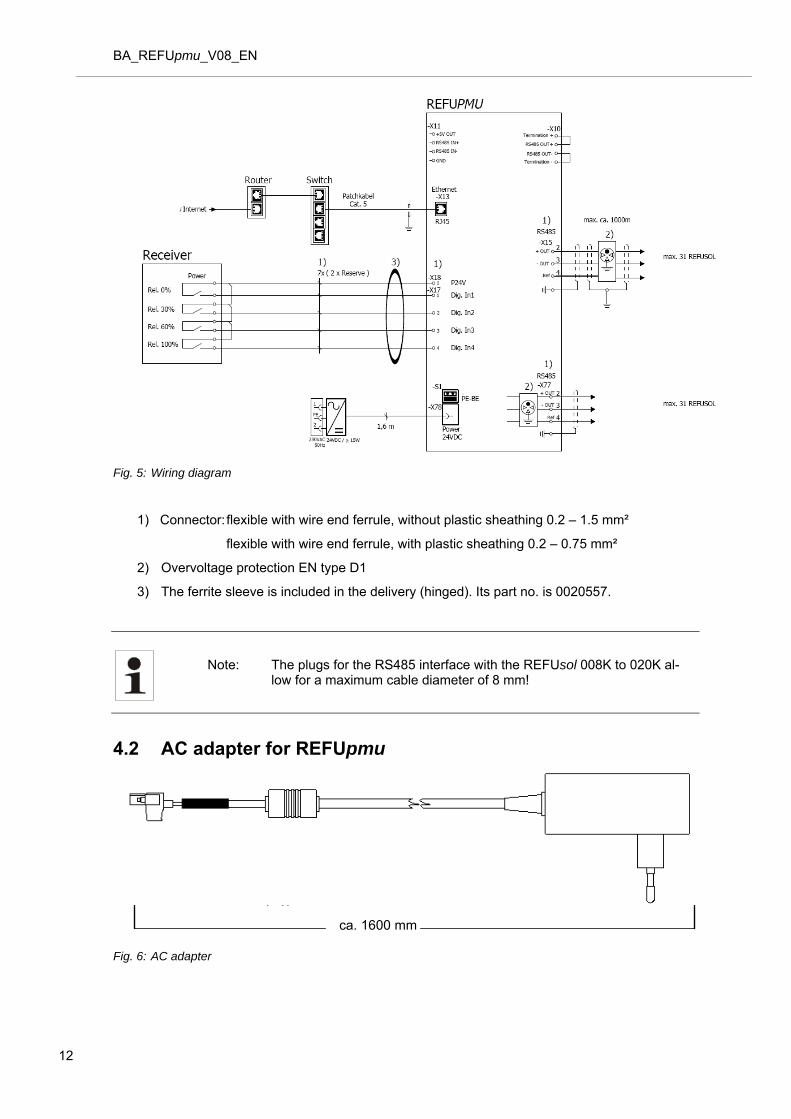
Fig. 5: Wiring diagram
1) Connector: flexible with wire end ferrule, without plastic sheathing 0.2 – 1.5 mm²
flexible with wire end ferrule, with plastic sheathing 0.2 – 0.75 mm²
2) Overvoltage protection EN type D1
3) The ferrite sleeve is included in the delivery (hinged). Its part no. is 0020557.
Note: The plugs for the RS485 interface with the REFUsol 008K to 020K al-low for a maximum cable diameter of 8 mm!
4.2 AC adapter for REFUpmu
ca. 1600 mm
Fig. 6: AC adapter
12

BA_REFUpmu_V08_EN
5. Configuration with PMUvis
Note: The PMUvis software supplied on CD with this description only oper-ates in connection with a PMU firmware version of 2.5 or higher and is used to configure the REFUpmu. The current version of the tool can be downloaded from the homepage at www.refusol.com.
5.1 System Requirements a. Windows XP SP3 32 Bit or higher (32- and 64-bit systems are supported).
b. Microsoft .NET Framework 4
5.2 Preparatory Measures
To properly install the REFUpmu, make the following basic settings at the inverter at menu Con-figuration > Communication.
Enter “72555” as password for the modifications.
For the transfer protocol of the RS485 interface must be set on the inverter “1”.
Deactivation of REFUlog activated to this extent. Inverter will stop to send independently, even if an internet-connection exist.
A clear USS address must be allocated to every inverter. The address 1-31 is the valid address area for each channel of the REFUpmu.
Set the baud rate at the REFUsol to 57600.
Note: To apply the modified data, switch the inverter off, wait for at least 30 seconds and on again using the DC switch. For more information, please refer to the operating instructions of the inverter.
5.3 Functional description
The REFUpmu can be completely set up with the PMUvis software tool.
The power reduction can be set as desired (in agreement with the power supply company).
The set total number of users of the RS485 network can be displayed.
Ethernet and RS485 interface settings can be made.
Date and time can be set.
The data of the REFUsol can be transferred to the “REFUlog” portal.
Specification of the idle power required by the power company
13

BA_REFUpmu_V08_EN
5.4 Installation
File < PMUvis_setup_x-x-x.exe > contains the installation package for PMUvis.
Execute the file to start installation.
Usually, the default installation options are the proper ones for most users. Confirm each installation window by clicking on next.
A link to the application is created on the desktop during installation.
Depending on whether an internet connection is present, there are two types of installation:
a. No Internet connection: Complete package with all auxiliary components.
b. Internet connection is available: Web installer to download any additional components required.
5.5 Applying PMUvis
Start PMUvis using the link on the desktop or the Windows Start menu.
Access the REFUpmu either
via the Ethernet interface using the factory-set default IP address 192.168.130.20 and port number 21062
or
using the USB port.
If you connect the REFUpmu to your computer via USB, a COM port is added to the Device Man-ager of your computer.
Select the new COM port and click “OK” to confirm.
Select 0 as “USS + RTP address” (USS + RTP Adresse) in the “Protokoll” (Protocol) field.
Fig. 7: Selecting the communication interface
14
BA_REFUpmu_V08_EN
5.6 PMUvis Main Window
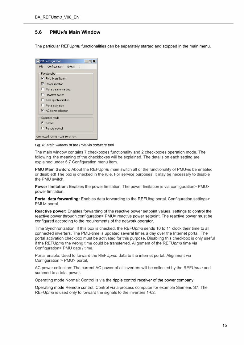
The particular REFUpmu functionalities can be separately started and stopped in the main menu.
Fig. 8: Main window of the PMUvis software tool
The main window contains 7 checkboxes functionality and 2 checkboxes operation mode. The following the meaning of the checkboxes will be explained. The details on each setting are explained under 5.7 Configuration menu item.
PMU Main Switch: About the REFUpmu main switch all of the functionality of PMUvis be enabled or disabled! The box is checked in the rule. For service purposes, it may be necessary to disable the PMU switch.
Power limitation: Enables the power limitation. The power limitation is via configuration> PMU> power limitation.
Portal data forwarding: Enables data forwarding to the REFUlog portal. Configuration settings> PMU> portal.
Reactive power: Enables forwarding of the reactive power setpoint values. Settings to control the reactive power through configuration> PMU> reactive power setpoint. The reactive power must be configured according to the requirements of the network operator.
Time Synchronization: If this box is checked, the REFUpmu sends 10 to 11 clock their time to all connected inverters. The PMU-time is updated several times a day over the Internet portal. The portal activation checkbox must be activated for this purpose. Disabling this checkbox is only useful if the REFUpmu the wrong time could be transferred. Alignment of the REFUpmu time via Configuration> PMU date / time.
Portal enable: Used to forward the REFUpmu data to the internet portal. Alignment via Configuration > PMU> portal.
AC power collection: The current AC power of all inverters will be collected by the REFUpmu and summed to a total power.
Operating mode Normal: Control is via the ripple control receiver of the power company.
Operating mode Remote control: Control via a process computer for example Siemens S7. The REFUpmu is used only to forward the signals to the inverters 1-62.
15

BA_REFUpmu_V08_EN
5.7 Menu Configuration
Using menu Configuration you can go to the various functions of the REFUpmu and inverter.
5.7.1 Power Reduction at Operation mode “Normal” Via” Configuration> PMU> Power limitation” the power limit is specified.
The ripple control signal of the power supply company is connected to the X17 "IN1" to "IN4" data ports.
16 values can be freely programmed. In the following example (Illustration No. 9, indicated in red), the "IN2" relay is switched on (this is shown with a 1).
Select the appropriate relay setting to enter or edit the percentage value.
Note: The configuration of the performance reduction is specified by the local power supply company through the relay ports! Factory-made setting: "IN1" – "IN4" ports with 0%, 30%, 60%, 100%.
Fig. 9: Relay configuration for power reduction
To apply the settings, click on Save.
16

BA_REFUpmu_V08_EN
5.7.2 Power reduction at Operation mode "Remote Control" The control of power is restricted via a process computer (eg Siemens S7). The digital inputs X17, IN1 to IN4 and the current input X74 for reactive power are disabled in this mode.
5.7.3 Portal The sub-menu portal via “configuration> PMU > portal”.
Here you can set how often the REFUpmu should send data to the portal.
For the interval time, the predefined values 5, 10, 60, 240, 360 and 720 minutes can be selected. And default value of 10 should be sufficient for most cases.
Click the portal test button to check the connection. If the setting is correct, this will be acknowl-edged by a message “test successful”.
If the test fails, proceed as follows:
1. Check the local IP settings, and adjust if necessary. Complete changes to the settings with reboot the REFUpmu.
2. Check the DNS server IP using the DOS command ipconfig / all. Complete changes to the settings with reboot the REFUpmu.
Note: If you do not want to transfer data to the REFUlog portal, deactivate the portal data transfer checkbox. The portal test can only be carried out correctly if the Ethernet interface is properly configured and the REFUpmu is connected to the internet.
Fig. 10: Interval configuration / portal test for portal data transfer
To apply the settings, click on Save and restart the REFUpmu.
By pressing the button "Send configuration" etc .the following data will be sent:
Firmware Version
Hardware Revision
Production date
5.7.4 Communication For communication, there are two possibilities:
17

BA_REFUpmu_V08_EN
Ethernet:
Enter or edit the IP settings, such as IP address, subnet mask and default gateway.
Factory settings on delivery of the REFUpmu
IP address: 192.168.130.020
Subnet mask: 255.255.255.000
Default gateway: 192.168.130.001
Fig. 11: IP settings of the REFUpmu
RS485
Call with configuration> PMU> Communication> RS485
The default setting for X15 and X77 is a baud rate of 57600. We recommend that you leave this setting as it is!
Note: Care must be taken to ensure that the same baud rate is set on the REFUpm and on the inverters!
Fig. 12: RS485 configuration
To apply the settings, click on Save and restart the REFUpmu.
5.7.5 Setting Date and Time
The configuration menu provides item set date/time which allows you to set the date and time.
You can either set the computer time or specify a date and a time.
Note: The time must be checked, and, if necessary corrected, when starting
18
BA_REFUpmu_V08_EN
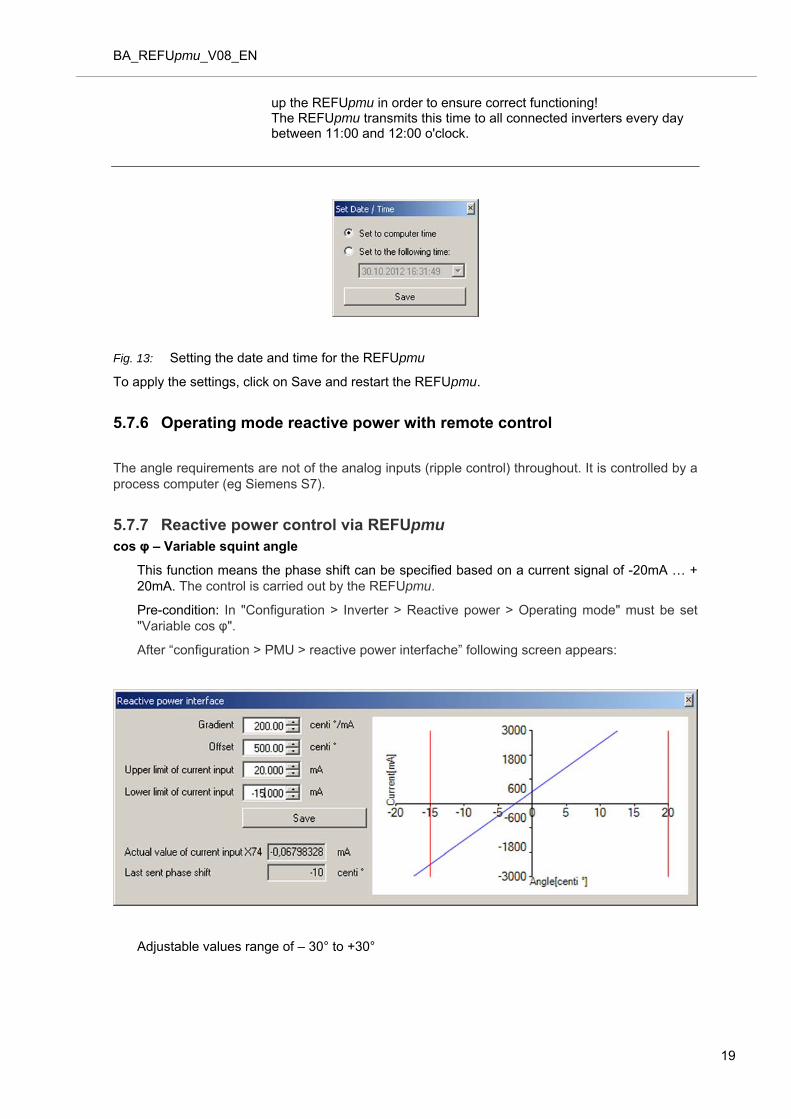
up the REFUpmu in order to ensure correct functioning! The REFUpmu transmits this time to all connected inverters every day between 11:00 and 12:00 o'clock.
Fig. 13: Setting the date and time for the REFUpmu
To apply the settings, click on Save and restart the REFUpmu.
5.7.6 Operating mode reactive power with remote control
The angle requirements are not of the analog inputs (ripple control) throughout. It is controlled by a process computer (eg Siemens S7).
5.7.7 Reactive power control via REFUpmu cos φ – Variable squint angle
This function means the phase shift can be specified based on a current signal of -20mA … + 20mA. The control is carried out by the REFUpmu.
Pre-condition: In "Configuration > Inverter > Reactive power > Operating mode" must be set "Variable cos φ".
After “configuration > PMU > reactive power interfache” following screen appears:
Adjustable values range of – 30° to +30°
19

BA_REFUpmu_V08_EN
5.7.8 Reactive power control by inverter
Note: The following items are sent from the REFUpmu after pressing the button "Send to all inverters" directly to the inverters. The inverters control then automatically, irrespective of the REFUpmu.
Operating mode
The mask appears via “Configuration> Inverter > Reactive power > Operating mode
Here you can select the operating mode. .
cos φ – fixed value
A fixed phase shift or a fixed cos φ shift factor can be set here.
Pre-condition: "Configuration > Inverter > Reactive power > Operating mode" must be set on "Static cos φ”.
20

BA_REFUpmu_V08_EN
Adjustable value range of – 30° to +30°
The value range for a fixed cos φ is between +0,866 and +1
cos φ – (P)-characteristic curve
This menu item can be entered into a table used to adjust the cos φ characteristic curves of the shift factor, displayed, depending on the current effective performance, as a percentage pro-portion of the nominal performance.
Pre-condition: "Configuration > Inverter > Reactive power > Operating mode" must be set on “Power characteristic curve"..
There is the option of either entering the φ phase shift in ° or the cos φ shift factor. The type of feeding-in (over-excited or under-excited) can likewise be determined.
Adjustable value range of – 30° to +30°
21

BA_REFUpmu_V08_EN
If the "Send to all inverters" button is pressed, the data entered is transmitted to all inverters and the "transmission status" dialogue is opened.
cos φ – (U)-characteristic curve
This menu item can be entered into a table used to adjust the cos φ characteristic curves of the shift factor, displayed (depending on the measured supply voltage shown as a percentage pro-portion of the nominal current).
Pre-condition: In "Configuration > Inverter > Reactive power > Operating mode" must be set to "Voltage characteristic curve”.
There is the option of either entering the φ phase shift in ° or the cos φ shift factor. The type of feeding-in (over-excited or under-excited) can likewise be determined.
Adjustable value range of –30° to +30°
If the "Send to all inverters" button is pressed, the data entered is transmitted to all inverters and the "transmission status" dialogue is opened.
22

BA_REFUpmu_V08_EN
Send information to all inverters
For the changes to be active, use the button "Send to all inverters”. After the button is clicked, the amended data is transmitted to the inverters and the transmission status opens. The transmission status displays the following information:
Status Farbe
Inverter has not responded white
Inverter has replied and storing the parameters was suc-cessful
green
23

BA_REFUpmu_V08_EN
Inverter has replied and storing the parameters was suc-cessful
red
Transmission did not occur even black
5.8 Menu Tools
5.8.1 User List
The Tools menu provides item user list which displays a list of the total number of users (all connected inverters, whether active or not).
Any inverter that is connected and properly configured is shown in green color (see Fig. No. 14).
Any inverter that is not connected or is not reached by the REFUpmu is shown in white color in the user list.
Example:
A inverter is properly configured at bus A, address 3 and 5 is properly feeding in.
All other addresses are not available for the REFUpmu.
If there are other users that are connected but not shown by the REFUpmu in this list, the inverter settings and the RS485 cabling must be checked.
Depending on the setting (power reduction refresh interval) of the REFUpmu, refreshing of the user list can take up to 8 minutes.
24

BA_REFUpmu_V08_EN
Fig. 14: User list of the inverters connected to the REFUpmu
5.8.2 Languages
Via "Extras > Language" can set the language. Available languages are English and German.
5.8.3 Device Information
Via "Extras > Device Information" following screen appears:
Fig. 15: Device Information
25

BA_REFUpmu_V08_EN
6. Wiring diagrams
6.1 REFUsol 008K-023K
26

BA_REFUpmu_V08_EN
27

BA_REFUpmu_V08_EN
28

BA_REFUpmu_V08_EN
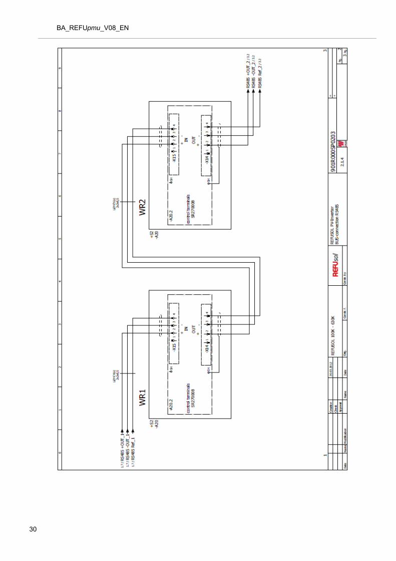
6.2 REFUsol 100K/500K/630K
29
BA_REFUpmu_V08_EN
30

BA_REFUpmu_V08_EN
31
BA_REFUpmu_V08_EN
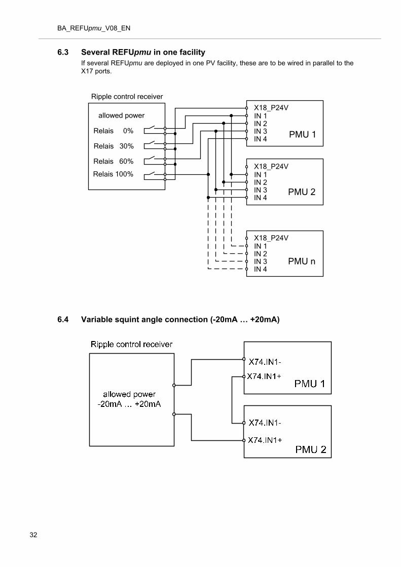
6.3 Several REFUpmu in one facility If several REFUpmu are deployed in one PV facility, these are to be wired in parallel to the X17 ports.
Relais 60%
Relais 100%
Relais 30%
Relais 0%
allowed power IN 1
IN 3IN 2
IN 4
X18_P24V
PMU 1
IN 1
IN 3IN 2
IN 4
X18_P24V
PMU 2
Ripple control receiver
IN 1
IN 3IN 2
IN 4
X18_P24V
PMU n
6.4 Variable squint angle connection (-20mA … +20mA)
32

BA_REFUpmu_V08_EN
7. Technical Data
Typ REFUpmu
AC adaptor
Supply voltage AC 230 V, 50Hz
Voltage range 115 to 230 V
Frequency range 50 / 60 Hz
Output voltage DC: 21 V to 24 V
Output Power 18 W
Output Current 750 mA
Basic device
Supply voltage DC: 21 V to 24 V
Power consumption 12 W
Current consumption max. 500 mA
Interfaces
USB interface 1
USB interface type Typ 2 (Device)
Ethernet interface 1
Ethernet interface type RJ45 port
RS485 interface 3
Digital inputs (terminal strip X17)
Digital input 4
Input voltage DC: -1 V to +33 V
Input current 8 mA to 9 mA
Potential isolation RJ45 port
RS485 interface No
Signal level input
0
1
-1 V to +5 V
+13 V to +33 V
With open input 0 level
Analog inputs (terminal strip X74)
Number 2
Input DC
Input impedance 100 ohm
Nominal input current +/-20 mA
Nominal input voltage +/-2,0 V
Control limit +/-25 mA, +/-2,5 V
Overload limit +/-30 mA, +/-3.0 V
33
BA_REFUpmu_V08_EN
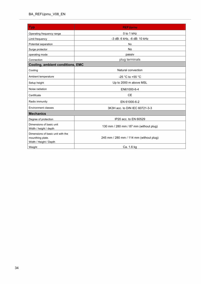
Typ REFUpmu
Operating frequency range 0 to 1 kHz
Limit frequency -3 dB: 6 kHz, -6 dB: 10 kHz
Potential separation No
Surge protector No
operating mode passiv
Connection plug terminals
Cooling, ambient conditions, EMC
Cooling Natural convection
Ambient temperature -25 °C to +55 °C
Setup height Up to 2000 m above MSL
Noise radiation EN61000-6-4
Certificate CE
Radio immunity EN 61000-6-2
Environment classes 3K3H acc. to DIN IEC 60721-3-3
Mechanics
Degree of protection IP20 acc. to EN 60529
Dimensions of basic unit
Width / height / depth 130 mm / 280 mm / 87 mm (without plug)
Dimensions of basic unit with the
mounthing plate.
Width / Height / Depth
245 mm / 280 mm / 114 mm (without plug)
Weight Ca. 1.6 kg
34

BA_REFUpmu_V08_EN
35

BA_REFUpmu_V08_EN
8. Notes
36

BA_REFUpmu_V08_EN
9. Contact
Please address any questions on failures or technical problems to:
Service hotline: +49 (0)7123 / 969-202 (from 8:00 a.m. to 5:00 p.m. on workdays)
Fax: +49 (0)7123 / 969-30202
Email: [email protected]
37

BA_REFUpmu_V08_EN
REFUsol GmbH
Uracherstraße 91
D-72555 Metzingen / Deutschland
Tel: +49 (0) 7123.969-202
Fax: +49 (0) 7123.969-30202
www.refusol.com
38
Item No.: 30707