regenerative braking system - ijirmps.org
TRANSCRIPT

IJIRMPS | Volume 9, Issue 4, 2021 ISSN: 2349-7300
IJIRMPS2104012 Website : www.ijirmps.org Email : [email protected] 77
Regenerative Braking System
1Omkar Khatavkar, 2Dhiren Parmar, 3Anmol Bagadekar, 4Omkar Bhoite, 5Prof. Prashant Nakate
1,2,3,4Students, 5Professor(Guide)
Department of Automobile Engineering
Dhole Patil College of Engineering, Wagholi
Abstract: The basic law of physics says "Energy can neither be created nor be destroyed, it can only be converted from one
form to another". When converting energy, huge amount of energy is lost to atmosphere as heat. It will be good if we could
store this energy somehow which is otherwise getting wasted, and reuse it next time we start to accelerate.
Regenerative braking refers to a system in which the kinetic energy of the vehicle is stored temporarily as an accumulative
energy during deceleration, and is reused as kinetic energy during acceleration or running. Regenerative braking is a small,
yet very important step towards our eventual independence from fossil fuels. These kinds of brakes allow batteries to be
used for longer periods of time without the need to be plugged into an external charger. These types of brakes also extend
the driving range of fully electric vehicles. Regenerative braking is a way to extend range of the electric vehicles. This system
is also applied in many hybrid vehicles to improve fuel economy. A normal car is only about 20% efficient, meaning some
80% of the energy it uses is wasted as heat created by friction. Regenerative braking could reclaim as much as half of that
wasted energy, which equates into more motion produced by the fuel then we are paying for instead of using that fuel to
create heat that is being dissipated uselessly into the environment.
Keywords: Regenerative Braking System
1. Introduction Regenerative Braking System is the way of slowing vehicle by using the motors as brakes. Instead of the surplus energy of the
vehicle being wasted as unwanted heat, the motors act as generators and return some of it to the overhead wires as electricity.
The vehicle is primarily powered from the electrical energy generated from the generator, which burns gasoline. This energy is
stored in a large battery, and used by an electric motor that provides motive force to the wheels. The regenerative braking taking
place on the vehicle is a way to obtain more efficiency, instead of converting kinetic energy to thermal energy through frictional
braking, the vehicle can convert a good fraction of its kinetic energy back into charge in the battery, using the same principle as an
alternator. Therefore, if you drive long distance without braking, you’ll be powering the vehicle entirely from gasoline. Regenerative
Braking System comes into its own when you’re driving in the city, and spending a good deal of your time braking. You will st ill
use more fuel in the city for each mile you drive than on the highway, though. Thermodynamics tells us that all inefficiency comes
from heat generation. For instance, when you brake, the brake pedals heat up and a quantity of heat, or energy, is lost to the outside
world. Friction in the engine produces heat in the same way.In most electric and hybrid electric vehicles on the road today, this is
accomplished by operating the traction motor as a generator, providing braking torque to the wheels and recharging the traction
batteries. The energy provided by regenerative braking can then be used for propulsion or to power vehicle accessories.
In Regenerative braking system instead of wasting the kinetic energy of vehicle in the form of heat it is converted into electrical
energy to be stored in batteries and capacitors or as mechanical energy of a flywheel having large moment of inertia. In this way a
large proportion of energy of vehicle is saved only to be used later for either accelerating the vehicle or for different electrical
purpose.
1.1 Need for Regenerative Brakes The regenerative braking system delivers a number of significant advantages over a car that only has friction brakes. In low-speed,
stop- and-go traffic where little deceleration is required; the regenerative braking system can provide the majority of the total
braking force. This vastly improves fuel economy with a vehicle, and further enhances the attractiveness of vehicles using
regenerative braking for city driving. At higher speeds, too, regenerative braking has been shown to contribute to improved fuel
economy – by as much as 20%.
Consider a heavy loaded truck having very few stops on the road. It is operated near maximum engine efficiency. The 80% of the
energy produced is utilized to overcome the rolling and aerodynamic road forces. The energy wasted in applying brake is about 2%.
Also its brake specific fuel consumption is 5%.
Now consider a vehicle, which is operated in the main city where traffic is a major problem here one has to apply brake frequently.
For such vehicles the wastage of energy by application of brake is about 60% to 65%.

IJIRMPS | Volume 9, Issue 4, 2021 ISSN: 2349-7300
IJIRMPS2104012 Website : www.ijirmps.org Email : [email protected] 78
Fig. A - Graphical Representation of Energy Usage of Two Vehicles
2. Basic Idea of Regenerative Brakes Concept of this regenerative brake is better understood from bicycle fitted with Dynamo. If our bicycle has a dynamo (a small
electricity generator) on it for powering the lights, we'll know it's harder to peddle when the dynamo is engaged than when it's
switched off. That's because some of our peddling energy is being "stolen" by the dynamo and turned into electrical energy in the
lights. If we're going along at speed and we suddenly stop peddling and turn on the dynamo, it'll bring us to a stop more quickly
than we would normally, for the same reason: it's stealing our kinetic energy. Now imagine a bicycle with a dynamo that's 100 times
bigger and more powerful. In theory, it could bring our bike to a halt relatively quickly by converting our kinetic energy into
electricity which we could store in a battery and use again later. And that's the basic idea behind regenerative brakes.
Electric trains, cars, and other electric vehicles are powered by electric motors connected to batteries. When we're driving along,
energy flows from the batteries to the motors, turning the wheels and providing us with the kinetic energy we need to move. When
we stop and hit the brakes, the whole process goes into reverse: electronic circuits cut the power to the motors. Now, our kinetic
energy and momentum makes the wheels turn the motors, so the motors work like generators and start producing electricity instead
of consuming it. Power flows back from these motor-generators to the batteries, charging them up. So a good proportion of the
energy we lose by braking is returned to the batteries and can be reused when we start off again. In practice, regenerative brakes
take time to slow things down, so most vehicles that use them also have ordinary (friction) brakes working alongside (that's also a
good idea in case the regenerative brakes fail).That's one reason why regenerative brakes don't save 100 percent of our braking
energy.
Fig. B - Basic Idea of Regenerative Brakes
2.1 The Motor as a Generator Vehicles driven by electric motors use the motor as a generator when using regenerative braking, it is operated as a generator during
braking and its output is supplied to an electrical load; the transfer of energy to the load provides the braking effect.
Regenerative braking is used on hybrid gas/electric automobiles to recoup some of the energy lost during stopping. This energy is
saved in a storage battery and used later to power the motor whenever the car is in electric mode.
3. Basic Elements of the System There are four elements required which are necessary for the working of regenerative braking system, these are:

IJIRMPS | Volume 9, Issue 4, 2021 ISSN: 2349-7300
IJIRMPS2104012 Website : www.ijirmps.org Email : [email protected] 79
3.1 Energy Storage Unit (ESU) The ESU performs two primary functions
(1) To recover & store braking energy
(2) To absorb excess engine energy during light load operation
The selection criteria for effective energy storage include:
(1) High specific energy storage density
(2) High energy transfer rate
(3) Small space requirement
The energy recaptured by regenerative braking might be stored in one of three devices:
(1) An electrochemical battery
(2) A flywheel
(3) Compressed air
(1) Batteries With this system as we know, the electric motor of a car becomes a generator when the brake pedal is applied. The kinetic energy
of the car is used to generate electricity that is then used to recharge the batteries. With this system, traditional friction brakes must
also be used to ensure that the car slows down as much as necessary. Thus, not all of the kinetic energy of the car can be harnessed
for the batteries because some of it is "lost" to waste heat. Some energy is also lost to resistance as the energy travels from the wheel
and axle, through the drive train and electric motor, and into the battery.
When the brake pedal is depressed, the battery receives a higher charge, which slows the vehicle down faster. The further the brake
pedal is depressed, the more the conventional friction brakes are employed.
The motor/generator produces AC, which is converted into DC, which is then used to charge the Battery Module. So, the
regenerative systems must have an electric controller that regulates how much charge the battery receives and how much the friction
brakes are used.
(2) Fly Wheels In this system, the translational energy of the vehicle is transferred into rotational energy in the flywheel, which stores the energy
until it is needed to accelerate the vehicle.
The benefit of using flywheel technology is that more of the forward inertial energy of the car can be captured than in batteries,
because the flywheel can be engaged even during relatively short intervals of braking and acceleration. In the case of batteries, they
are not able to accept charge at these rapid intervals, and thus more energy is lost to friction.
Another advantage of flywheel technology is that the additional power supplied by the flywheel during acceleration substantially
supplements the power output of the small engine that hybrid vehicles are equipped with.
3.2 Continuously Variable Transmission (CVT) The energy storage unit requires a transmission that can handle torque and speed demands in a steeples manner and smoothly control
energy flow to and from the vehicle wheels.
3.3 Controller An “ON-OFF” engine control system is used. That means that the engine is “ON” until the energy storage unit has been reached
the desired charge capacity and then is decoupled and stopped until the energy storage unit charge fall below its minimum
requirement.
3.4 Regenerative Brake Controllers Brake controllers are electronic devices that can control brakes remotely, deciding when braking begins ends, and how quickly the
brakes need to be applied. During the braking operation, the brake controller directs the electricity produced by the motor into the
batteries or capacitors. It makes sure that an optimal amount of power is received by the batteries, but also ensures that the inflow
of electricity isn't more than the batteries can handle.
The most important function of the brake controller, however, may be deciding whether the motor is currently capable of handling
the force necessary for stopping the car. If it isn't, the brake controller turns the job over to the friction brakes. In vehicles that use
these types of brakes, as much as any other piece of electronics on board a hybrid or electric car, the brake controller makes the
entir e regenerative braking process possible.
IJIRMPS | Volume 9, Issue 4, 2021 ISSN: 2349-7300
IJIRMPS2104012 Website : www.ijirmps.org Email : [email protected] 80
4. Different Types of Regenerative Braking System Based on the mode of storage of energy some of the system developed can be listed they are:
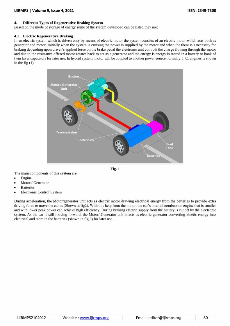
4.1 Electric Regenerative Braking In an electric system which is driven only by means of electric motor the system consists of an electric motor which acts both as
generator and motor. Initially when the system is cruising the power is supplied by the motor and when the there is a necessity for
braking depending upon driver’s applied force on the brake pedal the electronic unit controls the charge flowing through the motor
and due to the resistance offered motor rotates back to act as a generator and the energy is energy is stored in a battery or bank of
twin layer capacitors for later use. In hybrid system, motor will be coupled to another power source normally. I. C. engines is shown
in the fig (1).
Fig. 1
The main components of this system are:
Engine
Motor / Generator
Batteries
Electronic Control System
During acceleration, the Motor/generator unit acts as electric motor drawing electrical energy from the batteries to provide extra
driving force to move the car as (Shown in fig2). With this help from the motor, the car’s internal combustion engine that is smaller
and with lower peak power can achieve high efficiency. During braking electric supply from the battery is cut off by the electronic
system. As the car is still moving forward, the Motor/ Generator unit is acts as electric generator converting kinetic energy into
electrical and store in the batteries (shown in fig 3) for later use.

IJIRMPS | Volume 9, Issue 4, 2021 ISSN: 2349-7300
IJIRMPS2104012 Website : www.ijirmps.org Email : [email protected] 81
Fig. 2 - Showing Energy Consumption from Battery
Fig. 3 - Showing Charging of Battery when Brake Applied
4.2 Hydraulic Regenerative Brakes Hydrostatic Regenerative Braking (HRB) system uses electrical/electronic components as well as hydraulics to improve vehicle
fuel economy. An alternative regenerative braking system is being developed by the Ford Motor Company and the Eaton
Corporation. It's called Hydraulic Power Assist or HPA. With HPA, when the driver steps on the brake, the vehicle's kinetic energy
is used to power a reversible pump, which sends hydraulic fluid from a low pressure accumulator (a kind of storage tank) inside the
vehicle into a high pressure accumulator. The pressure is created by nitrogen gas in the accumulator, which is compressed as the
fluid is pumped into the space the gas formerly occupied. This slows the vehicle and helps bring it to a stop. The fluid remains
under pressure in the accumulator until the driver pushes the accelerator again, at which point the pump is reversed and the
pressurized fluid is used to accelerate the vehicle, effectively translating the kinetic energy that the car had before braking into the
mechanical energy that helps get the vehicle back up to speed. It's predicted that a system like this could store 80 percent of the
momentum lost by a vehicle during deceleration and use it to get the vehicle moving again.
The Hydrostatic Regenerative Braking (HRB) system is intended for commercial vehicles and mobile equipment. The company
says that initial measurements show that the HRB system reduces the fuel consumption in these vehicles by up to 25%.
In the HRB system, braking energy is converted to hydraulic pressure and stored in a high-pressure hydraulic accumulator. When
the vehicle accelerates, the stored hydraulic energy is applied to the transmission reducing the energy that the combustion engine
has to provide. An electronic controller and a hydraulic valve manifold control the process.
At present, these hydraulic regenerative brakes are noisy and prone to leaks; however, once all of the details are ironed out, such
systems will probably be most useful in large trucks.

IJIRMPS | Volume 9, Issue 4, 2021 ISSN: 2349-7300
IJIRMPS2104012 Website : www.ijirmps.org Email : [email protected] 82
Fig. D - Hydraulic Regenerative Brake (HRB)
4.3 Fly Wheels Regenerative brakes may seem very hi-tech, but the idea of having "energy-saving Reservoirs" in machines is nothing new. Engines
have been using energy-storing devices called flywheels virtually since they were invented.
The basic idea is that the rotating part of the engine incorporates a wheel with a very heavy metal rim, and this drives whatever
machine or device the engine is connected to. It takes much more time to get a flywheel-engine turning but, once it's up to speed,
the flywheel stores a huge amount of rotational energy. A heavy spinning flywheel is a bit like a truck going at speed: it has huge
momentum so it takes a great deal of stopping and changing its speed takes a lot of effort. That may sound like a drawback, but it's
actually very useful. If an engine supplies power erratically, the flywheel compensates, absorbing extra power and making up for
temporary lulls, so the machine or equipment it's connected to is driven more smoothly.
It's easy to see how a flywheel could be used for regenerative braking. In something like a bus or a truck, you could have a heavy
flywheel that could be engaged or disengaged from the transmission at different times. You could engage the flywheel every time
you want to brake so it soaked up some of your kinetic energy and brought you to a halt. Next time you started off, you'd use the
flywheel to return the energy and get you moving again, before disengaging it during normal driving. The main drawback of using
flywheels in moving vehicles is, of course, their extra weight. They save you energy by storing power you'd otherwise squander in
brakes, but they also cost you energy because you have to carry them around all the time.
The transfer of energy in both directions (captured from the drive-line during coasting and braking, and released to the drive-line
for boost) is managed through a CVT (Continuously Variable Transmission) gear box. Packaged inside a single housing is a shaft
mounted flywheel that is connected via a chain/gear or belt/pulley drive to a series of discs and rollers (the CVT). During braking
and coasting, the flywheel spools-up (accelerates as it spins) and absorbs a storehouse of otherwise wasted energy (heat from friction
brakes). During power delivery, as the vehicle begins to accelerate, the pent-up energy in the flywheel is released and it turns the
shaft. The rollers within the CVT can change position across the discs and either retard or augment the torque of the spinning
flywheel shaft much like a conventional step-up or step-down gear box. This “gearing” is necessary, because unlike aircraft, and to
a certain extent watercraft, which travel at a relatively constant load and speed, earth-bound vehicles travel at regularly and greatly
varying speeds and loads as they negotiate traffic and topography. It is this variable output velocity that allows for smooth power
transmission from the flywheel to the drive-line as the vehicle travels over the roadway.
Advanced transmissions that incorporate hi-tech flywheels are now being used as regenerative systems in such things as formula-1
cars, where they're typically referred to as Kinetic Energy Recovery Systems (KERS).
Pros of Flywheel Systems
(1) Compact Weight and Size - The entire system (the CVT, the flywheel and the housing) is roughly half the weight and
packaging of a battery hybrid system.
(2) Twice as Efficient - Battery-electric structures lose kinetic potential during the conversion of energy from mechanical to
electrical to chemical, and then back again. It’s a fundamental of the Second Law of Thermodynamics: transforming energy
from one form to another introduces losses. Battery electrics are approximately 34 percent efficient. Flywheel drives are all
mechanical and suffer no conversion losses. Most of the energy loss that does occur comes from normal friction between
moving parts. These systems are about 70 percent efficient.
(3) Lower Cost - Smaller size and weight and reduced complexity make these arrangements about one quarter the cost of a
battery-electric system.

IJIRMPS | Volume 9, Issue 4, 2021 ISSN: 2349-7300
IJIRMPS2104012 Website : www.ijirmps.org Email : [email protected] 83
4.4 Use in Compressed Air Regenerative brakes could be employed in compressed air cars to refill the air tank during braking. By absorbing the kinetic energy
(necessary for braking), using the same for compressing the air and reuse these compressed air while powering the car.
4.5 Regenerative Braking using Nitilon Spring From fig it is clear that while braking the kinetic energy is stored in form of potential energy in spring. When the system actually
demands for the acceleration this potential energy stored is given back to the wheels to power them.
Fig. E - Regenerative Braking using Nitilon Spring
5. Methodology
Did some research on this topic
Viewed some previously done projects
Gathered some more information about required materials
Created a prototype diagram
Collecting all the required parts for the project prototype
Parts used for the project are :
a) Motor (300 RPM)
b) Motor (1000 RPM)
c) Wheels
d) Brake Lever
e) LED Lights
f) 12V adapter
Arranging all the parts on the platform in a manner
Placing two wooden blocks on the platform
These wooden blocks are supporting the rod
On that rod a 1000 RPM motor is attached and wheels are placed
When we power the system the 1000 RPM motor spins the wheel
Then a lever arrangement is made to apply brakes
A 300 RPM motor is attached to the brakes
When the brake is applied the energy is generated and seen in the form of electrical energy
This motor is then connected to the LED’s where the energy is transferred
Around 6V of energy is generated in LED’s
This kinetic energy converted into electrical energy then powers the LED lights
So this is how the regenerative braking prototype works and shows how the regenerative braking system generates energy to
power the battery of the vehicle

IJIRMPS | Volume 9, Issue 4, 2021 ISSN: 2349-7300
IJIRMPS2104012 Website : www.ijirmps.org Email : [email protected] 84
5.1 Fabrication
List of Materials used in Fabrication
Sr. No. Name of Parts Used Description Quantity
1 Square Bar 40 * 40 Hollow Bar (M.S.) 8m
2 Journal Bearing Internal Dia.12 mm 2 piece
3 Brake Wheel Outer Dia. 8 cm 1 piece
4 Solid Shaft Outer Dia.12 mm 1.5 m
5 Bicycle Wheel Inner Dia. 12 mm 1 piece
6 Brake Spindle 40 * 40 Hollow Bar (M.S.) 0.6 m
7 Motor 1000 rpm 1 piece
8 Pulley Internal Dia.12 mm 2 piece
9 LEDs 12V 6 piece
10 Electric Wires Copper Wire 6 m
11 DC Motor Brushed DC 12V 1 piece
5.2 Design
Design Consideration Regenerative braking system may not suffice the basic requirement of braking system alone. This is because of limitation of energy
dissipation at very high power. The storage and generation systems may not be capable to operate at those levels due to design
limitations. Due to critical level of safety involved with the system, reliability becomes debatable and it necessitates a frictional
braking system to co-exist with electrical regenerative braking system. [24] This forms a hybrid braking system [25], which means:
1. Just like hybrid propulsion systems, there can be many design configurations and control strategies.
2. Design and control of system should be such that they ensure vehicle’s desired braking performance while at the same time
capturing as much energy as possible.
During developing strategies, a careful consideration of braking behavior and its characteristics with respect to speed, braking
power, deceleration rate etc. must be made.

IJIRMPS | Volume 9, Issue 4, 2021 ISSN: 2349-7300
IJIRMPS2104012 Website : www.ijirmps.org Email : [email protected] 85
Fig. - Disassembled Parts
Fig. - Assembled Parts

IJIRMPS | Volume 9, Issue 4, 2021 ISSN: 2349-7300
IJIRMPS2104012 Website : www.ijirmps.org Email : [email protected] 86
6. Applications
Use in Motor Sports
Fig. 2.1 - A Flybrid Systems Kinetic Energy Recovery System
The first of these systems to be revealed was the Flybrid. This system weighs 24 kg and has an energy capacity of 400 kJ after
allowing for internal losses. A maximum power boost of 60 kW (81.6 PS, 80.4 HP) for 6.67 seconds is available. The 240 mm
diameter flywheel weighs 5.0 kg and revolves at up to 64,500 rpm. Maximum torque is 18 Nm (13.3 ft lbs). The system occupies a
volume of 13 liter.
Formula One
Fig. 2.2 - A KERS Flywheel

IJIRMPS | Volume 9, Issue 4, 2021 ISSN: 2349-7300
IJIRMPS2104012 Website : www.ijirmps.org Email : [email protected] 87
Formula One have stated that they support responsible solutions to the world's environmental challenges, and the FIA allowed the
use of 81 hp (60 kW; 82 PS) KERS in the regulations for the 2009 Formula One season. Teams began testing systems in 2008:
energy can either be stored as mechanical energy (as in a flywheel) or as electrical energy (as in a battery or super capacitor).
Two minor incidents were reported during testing of KERS systems in 2008. The first occurred when the Red Bull Racing team
tested their KERS battery for the first time in July: it malfunctioned and caused a fire scare that led to the team's factory being
evacuated [3]. The second was less than a week later when a BMW Sauber mechanic was given an electric shock when he touched
Christian Klien's KERS-equipped car during a test at the Jerez circuit [4]. With the introduction of KERS in the 2009 season, four
teams used it at some point in the season:
Ferrari, Renault, BMW, and McLaren. During the season, Renault and BMW stopped using the system. Vodafone McLaren
Mercedes became the first team to win a F1 GP using a KERS equipped car when Lewis Hamilton won the Hungarian Grand Prix
on 26 July 2009. Their second KERS equipped car finished fifth. At the following race, Lewis Hamilton became the first driver to
take pole position with a KERS car, his teammate, Heikki Kovalainen qualifying second. This was also the first instance of an all
KERS front row. On 30 August 2009, Kimi Räikkönen won the Belgian Grand Prix with his KERS equipped Ferrari. It was the
first time that KERS contributed directly to a race victory, with second placed Giancarlo Fisichella claiming "Actually, I was quicker
than Kimi. He only took me because of KERS at the beginning" [5].
Auto Part Makers Bosch Motorsport Service is developing a KERS for use in motor racing. These electricity storage systems for hybrid and engine
functions include a lithium-ion battery with scalable capacity or a flywheel, a four to eight-kilogram electric motor (with a maximum
power level of 60 kW or 80 hp), as well as the KERS controller for power and battery management. Bosch also offers a range of
electric hybrid systems for commercial and light-duty applications [6].
Car Makers Automakers including Honda have been testing KERS systems. At the 2008 1,000 km of Silverstone, Peugeot Sport unveiled the
Peugeot 908 HY, a hybrid electric variant of the diesel 908, with KERS. Peugeot planned to campaign the car in the 2009 Le Mans
Series season, although it was not capable of scoring championship points [7]. Peugeot plans also a compressed air regenerative
braking power train called Hybrid Air [8]. Vodafone McLaren Mercedes began testing of their KERS in September 2008 at the
Jerez test track in preparation for the 2009 F1 season; although at that time it was not yet known if they would be operating an
electrical or mechanical system [9]. In November 2008 it was announced that Free scale Semiconductor would collaborate with
McLaren Electronic Systems to further develop its KERS for McLaren's Formula One car from 2010 onwards. Both parties believed
this collaboration would improve McLaren's KERS system and help the system filter down to road car technology [10].
Toyota has used a super capacitor for regeneration on Supra HV-R hybrid race car that won the 24 Hours of Tokachi race in July
2007 [11]. BMW has used regenerative braking on their E90 3 Series as well as in current models like F255 Series under the
Efficient Dynamics moniker. Volkswagen have regenerative braking technologies under the Blue Motion brand in such models as
the MK7 Golf and MK7 Golf Estate/Wagon models, other VW group brands like SEAT, Skoda and Audi.
Motorcycles KTM racing boss Harald Bartol has revealed that the factory raced with a secret kinetic energy recovery system (KERS) fitted to
Tommy Koyama's motorcycle during the 2008 season-ending 125cc Valencian Grand Prix. This was against the rules, so they were
banned from doing it afterwards.
Races Automobile Club de l'Ouest, the organizer behind the annual 24 Hours of Le Mans event and the Le Mans Series is currently
"studying specific rules for LMP1 that will be equipped with kinetic energy recovery system." Peugeot was the first manufacturer
to unveil a fully functioning LMP1 car in the form of the 908 HY at the 2008 Auto sport 1000 km race at Silverstone [12]
Bicycles Regenerative braking is also possible on a non-electric bicycle. The EPA, working with students from the University of Michigan,
developed the Hydraulic Regenerative Brake Launch Assist (RBLA) [13]. It is available on electric bicycles with direct-drive hub
motors.
Cars Many electric vehicles employ regenerative braking since the first used in the US by the AMC Amitron concept car [14].
Regenerative braking systems are not able to fully emulate traditional brake function for drivers, but there are continuing
advancements [15]. The calibrations used to determine when energy will be regenerated and when friction braking is used to slow
down the vehicle affects the way the driver feels the braking action [16].
Examples of cars include:
Audi E-tron
Ford Fusion Hybrid

IJIRMPS | Volume 9, Issue 4, 2021 ISSN: 2349-7300
IJIRMPS2104012 Website : www.ijirmps.org Email : [email protected] 88
Hyundai Kona Electric
Nissan Leaf
Tesla Model 3
Toyota Prius
Some of vehicles using regenerative brake:
(1) Toyota Prius
(2) Ford FUSION
(3) Tesla Roadster Electric Car
(4) Vectrix Electric Maxi-Scooter
(5) KERS is used in F1 cars
Fig. - Ford Fusion
7. Comparisons
7.1 Advantages of Regenerative Braking over Conventional Braking
Energy Conservation The flywheel absorbs energy when braking via a clutch system slowing the car down and speeding up the wheel. To accelerate,
another clutch system connects the flywheel to the drive train, speeding up the car and slowing down the flywheel. Energy is
therefore conserved rather than wasted as heat and light which is what normally happens in the contemporary shoe/disc system.
Wear Reduction An electric drive train also allows for regenerative breaking which increases Efficiency and reduces wear on the vehicle brakes.
In regenerative braking, when the motor is not receiving power from the battery pack, it resists the turning of the wheels, capturing
some of the energy of motion as if it were a generator and returning that energy to the battery pack. In mechanical brakes; lessening
wear and extending brake life is not possible. This reduces the use of use the brake.
Fuel Consumption The fuel consumption of the conventional vehicles and regenerative braking system vehicles was evaluated over a course of various
fixed urban driving schedules.
The results are compared as shown in figure. Representing the significant cost saying to its owner, it has been proved the
regenerative braking is very fuel-efficient. The Delhi Metro saved around 90,000 tons of carbon dioxide (CO2) from being released
into the atmosphere by regenerating 112,500 megawatt hours of electricity through the use of regenerative braking systems between
2004 and 2007. It is expected that the Delhi Metro will save over 100,000 tons of CO2 from being emitted per year once its phase
II is complete through the use of regenerative braking. The energy efficiency of a conventional car is only about 20 percent, with
the remaining 80 percent of its energy being converted to heat through friction. The miraculous thing about regenerative braking is
that it may be able to capture as much as half of that wasted energy and put it back to work. This could reduce fuel consumption by
10 to 25 percent. Hydraulic regenerative braking systems could provide even more impressive gains, potentially reducing fuel use
by 25 to 45 percent.
Braking is Not Total Loss Conventional brakes apply friction to convert a vehicle’s kinetic energy into heat. In energy terms, therefore, braking is a total loss:
once heat is generated, it is very difficult to reuse. The regenerative braking system, however, slows a vehicle down in a different
way.

IJIRMPS | Volume 9, Issue 4, 2021 ISSN: 2349-7300
IJIRMPS2104012 Website : www.ijirmps.org Email : [email protected] 89
7.2 Comparison of Dynamic Brakes and Regenerative Brakes Dynamic brakes ("rheostat brakes" in the UK), unlike regenerative brakes, dissipate the electric energy as heat by passing the current
through large banks of variable resistors. Vehicles that use dynamic brakes include forklifts, Diesel-electric locomotives, and
streetcars. This heat can be used to warm the vehicle interior, or dissipated externally by large radiator-like cowls to house the
resistor banks.
The main disadvantage of regenerative brakes when compared with dynamic brakes is the need to closely match the generated
current with the supply characteristics and increased maintenance cost of the lines. With DC supplies, this requires that the voltage
be closely controlled. Only with the development of power electronics has this been possible with AC supplies, where the supply
frequency must also be matched (this mainly applies to locomotives where an AC supply is rectified for DC motors).
A small number of mountain railways have used 3-phase power supplies and 3- phase induction motors. This results in a near
constant speed for all trains as the motors rotate with the supply frequency both when motoring and braking.
7.3 Why Regenerative Brakes are assisted with the Frictional Brake? Traditional friction-based braking is used in conjunction with mechanical regenerative braking for the following reasons:
The regenerative braking effect drops off at lower speeds; therefore the friction brake is still required in order to bring the
vehicle to a complete halt. Physical locking of the rotor is also required to prevent vehicles from rolling down hills.
The friction brake is a necessary back-up in the event of failure of the regenerative brake.
Most road vehicles with regenerative braking only have power on some wheels (as in a two-wheel drive car) and regenerative
braking power only applies to such wheels, so in order to provide controlled braking under difficult conditions (such as in wet
roads) friction based braking is necessary on the other wheels.
The amount of electrical energy capable of dissipation is limited by either the capacity of the supply system to absorb this
energy or on the state of charge of the battery or capacitors. No regenerative braking effect can occur if another electrical
component on the same supply system is not currently drawing power and if the battery or capacitors are already charged. For
this reason, it is normal to also incorporate dynamic braking to absorb the excess energy.
Under emergency braking it is desirable that the braking force exerted be the maximum allowed by the friction between the
wheels and the surface without slipping, over the entire speed range from the vehicle's maximum speed down to zero. The
maximum force available for acceleration is typically much less than this except in the case of extreme high-performance
vehicles. Therefore, the power required to be dissipated by the braking system under emergency braking conditions may be
many times the maximum power which is delivered under acceleration. Traction motors sized to handle the drive power may
not be able to cope with the extra load and the battery may not be able to accept charge at a sufficiently high rate. Friction
braking is required to absorb the surplus energy in order to allow an acceptable emergency braking performance.
8. Conclusion The beginning of the 21st century could very well mark the final period in which internal combustion engines are commonly used
in cars. Already automakers are moving toward alternative energy carriers, such as electric batteries, hydrogen fuel and even
compressed air. Regenerative braking is a small, yet very important, step toward our eventual independence from fossil fuels. These
kinds of brakes allow batteries to be used for longer periods of time without the need to be plugged into an external charger. These
types of brakes also extend the driving range of fully electric vehicles. In fact, this technology has already helped bring us cars like
the Tesla Roadster, which runs entirely on battery power. Sure, these cars may use fossil fuels at the recharging stage -- that is, if
the source of the electricity comes from a fossil fuel such as coal -- but when they're out there on the road, they can operate with no
use of fossil fuels at all, and that's a big step forward. When you think about the energy losses incurred by battery-electric hybrid
systems, it seems plausible to reason that efficient flywheel hybrids would soon become the norm. But of course it’s not quite so
black and white, and further analysis shows that a combination of battery-electric and flywheel energy storage is probably the ideal
solution for hybrid vehicles.
As designers and engineers perfect regenerative braking systems, they will become more and more common. All vehicles in motion
can benefit from utilizing regeneration to recapture energy that would otherwise be lost.
References [1] Cibulka J. Kinetic energy recovery system by means of flywheel energy storage. Advanced engineering. 3. 2009
[2] howstuffswork.com
[3] Hewko L. O. Automotive traction drive CVTs – An overview. SAE paper 861355
[4] Juan W. Dixon, Micah Ortúzar, Eduardo Wiechmann. Regenerative Braking for an Electric Vehicle Using Ultracapacitors
and a Buck-Boost Converter
[5] Chris Brockbank. Development of Full-Toroidal Traction Drives in Flywheel Based Mechanical Hybrids”
[6] Ziqiang Chen, Jiaxi Qiang, Jianhui He, Lin Yang. Intelligent Regenerative Braking Control of Hybrid Buses

IJIRMPS | Volume 9, Issue 4, 2021 ISSN: 2349-7300
IJIRMPS2104012 Website : www.ijirmps.org Email : [email protected] 90
[7] S. J. Clegg. A Review of Regenerative Braking System. Institute of Transport Studies, University of Leeds, Working paper
of 471, 1996
[8] Regenerative braking boosts green credentials. Railway Gazette International. 2 July 2007
Acknowledgement The satisfaction that accompanies the successful completion of this seminar report would be incomplete without the mention of the
people who made it possible, without whose constant guidance and encouragement would have made efforts go in vain. I consider
myself privileged to express gratitude and respect towards all those who guided us through the completion of this project.
I convey thanks to my seminar guide Prof. Prashant Nakate as of Department of Automobile Engineering, for providing
encouragement, constant support and guidance which was of a great help to complete this project successfully.
I am grateful to Prof. Siddaraj Allurkar, Head of the Department of Automobile Engineering for giving me the support and
encouragement that was necessary for the completion of this project.
I would also like to express my gratitude to Dr. Nihar Valimbe Principal of Dhole Patil College of Engineering for providing us
congenial environment to work in.
Mr. OMKAR KHAYAVKAR
Mr. DHIREN PARMAR
Mr. ANMOL BAGADEKAR
Mr. OMKAR BHOITE
(BE Automobile Engg.)