register data flow - ece/cs 752 fall 2019
TRANSCRIPT

Register Data FlowECE/CS 752 Fall 2017
Prof. Mikko H. LipastiUniversity of Wisconsin-Madison
Register Data Flow Techniques• Register Data Flow
– Resolving Anti-dependences– Resolving Output Dependences– Resolving True Data Dependences
• Tomasulo’s Algorithm [Tomasulo, 1967]– Modified IBM 360/91 Floating-point Unit– Reservation Stations– Common Data Bus– Register Tags– Operation of Dependency Mechanisms

The Big PictureINSTRUCTION PROCESSING CONSTRAINTS
Resource Contention Code Dependences
Control Dependences Data Dependences
True Dependences
Anti-Dependences Output Dependences
Storage Conflicts
(Structural Dependences)
(RAW)
(WAR) (WAW)

Register Data FlowEach ALU Instruction:
Need Availability of Fn (Structural Dependences)Need Availability of Rj, Rk (True Data Dependences)Need Availability of Ri (Anti-and output Dependences)
INSTRUCTION EXECUTION MODEL
Ri Fn (Rj, Rk)
Dest.Reg.
Funct.Unit
SourceRegisters
R0R1
Rm
FU1
FU2
FUn
Interconnect
•••
•••
Registers FunctionalUnits
“Register Transfer”
“Read”“Write”
“Execute”

Causes of (Register) Storage ConflictREGISTER RECYCLING
MAXIMIZE USE OF REGISTERSMULTIPLE ASSIGNMENTS OF VALUES TO REGISTERS
OUT OF ORDER ISSUING AND COMPLETIONLOSE IMPLIED PRECEDENCE OF SEQUENTIAL CODELOSE 1-1 CORRESPONDENCE BETWEEN VALUES AND
REGISTERS
Ri•••
Ri
••• DEF
USE
USE
DEF•••
Ri
Ri
•••
•••
WAW
WAR
First instance of Ri
Second instance of Ri
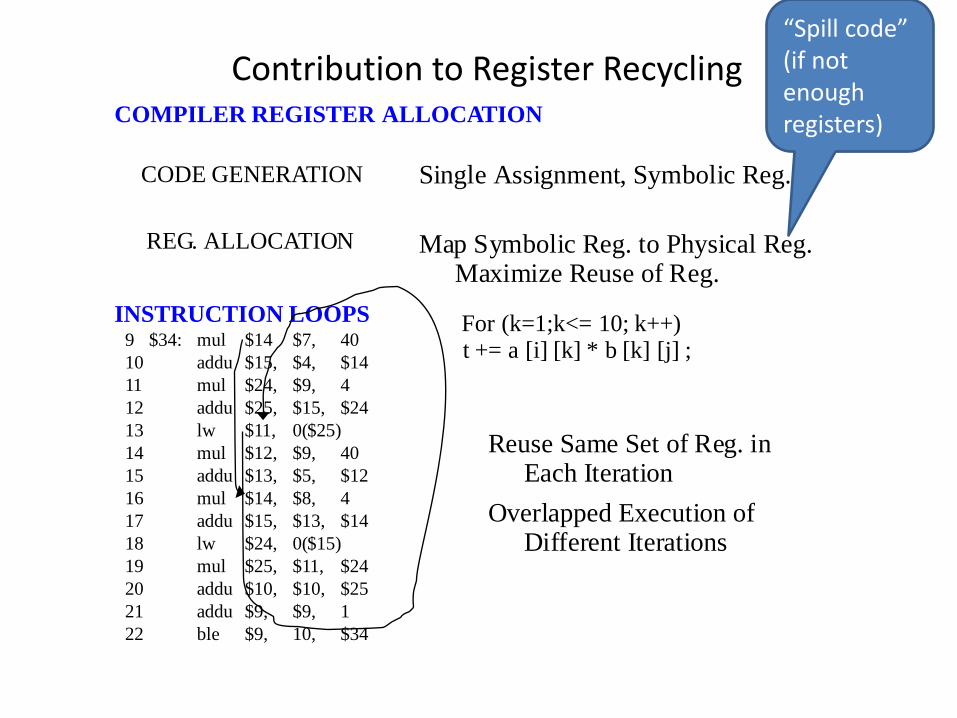
Contribution to Register RecyclingCOMPILER REGISTER ALLOCATION
INSTRUCTION LOOPS
Single Assignment, Symbolic Reg.
Map Symbolic Reg. to Physical Reg. Maximize Reuse of Reg.
CODE GENERATION
REG. ALLOCATION
Reuse Same Set of Reg. in Each Iteration
Overlapped Execution of Different Iterations
For (k=1;k<= 10; k++) t += a [i] [k] * b [k] [j] ;9 $34: mul $14 $7, 40
10 addu $15, $4, $1411 mul $24, $9, 412 addu $25, $15, $2413 lw $11, 0($25)14 mul $12, $9, 4015 addu $13, $5, $1216 mul $14, $8, 417 addu $15, $13, $1418 lw $24, 0($15)19 mul $25, $11, $2420 addu $10, $10, $2521 addu $9, $9, 122 ble $9, 10, $34
“Spill code”(if not enough registers)

Resolving Anti-Dependences
STALL DISPATCHINGDELAY DISPATCHING OF (2)REQUIRE RECHECKING AND REACCESSING
COPY OPERANDCOPY NOT-YET-USED OPERAND TO PREVENT BEING
OVERWRITTENMUST USE TAG IF ACTUAL OPERAND NOT-YET-AVAILABLE
RENAME REGISTERHARDWARE ALLOCATION
(2) R3 R5 + 1
Must Prevent (2) from completing • • •(1) R4 R3 + 1
before (1) is dispatched.
R3 <= …<= R3
R3’ <= …<= R3’
WAR only
WAR and WAW

Resolving Output Dependences
© 2005 Mikko Lipasti 8
STALL DISPATCHING/ISSUINGDENOTE OUTPUT DEPENDENCEHOLD DISPATCHING UNTIL RESOLUTION OF DEPENDENCEALLOW DECODING OF SUBSEQUENT INSTRUCTIONS
RENAME REGISTERHARDWARE ALLOCATION
Must Prevent (3) from completing before (1) completes.
(1) R3 R3 op R5
R3
(3) R3 R5 + 1
•••
•••
R3 <= …<= R3
R3’ <= …<= R3’

Register Renaming
© 2005 Mikko Lipasti 9
Register Renaming Resolves:
Anti-Dependences Output Dependences
Design of Redundant Registers:Number:
OneMultiple
Allocation:Fixed for Each RegisterPooled for all Regsiters
Location:Attached to Register File
(Centralized)Attached to functional units
(Distributed)
Architected PhysicalRegisters Registers
R1R2•••Rn
P1P2•••Pn
•••Pn + k

Register Renaming in the RIOS-I FPU
© 2005 Mikko Lipasti 10
FPU Register Renaming
Map table32 x 6
32 33 34 35 36 37 38 39Free Listhead tail
head
tailrelease
Pending Target Return Queue
FAD 3 2 1 FAD 3 2 1OP T S1 S2 S3 OP T S1 S2 S3
Incoming FPU instructions pass through a renaming table prior to decode
The 32 architectural registers are remapped to 40 physical registers
Physical register names are used within the FPU
Complex control logic maintains active register mapping
Simplified FPU Register Model
Fload R7 <= Mem[] (P32 alloc)
R7: P32
7
Free when Fload R7 commits
Fload R7 <= Mem[] (P32 freed)…
<= R7 (actual last use) (P32)…

Resolving True Data Dependences
© 2005 Mikko Lipasti 11
STALL DISPATCHING
ADVANCE INSTRUCTIONS
“DYNAMIC EXECUTION”
Reservation Station + Complex Forwarding
Out-of-order (OoO) Execution
Try to Approach the “Data-Flow Limit”
REGISTER READ
ALU OP
REGISTER WRITE
(1) R2 R1 + 1 • • •(2) R3 R2 • • •(3) R4 R3
1) Read register(s), get “IOU” if not ready2) Advance to reservation station3) Wait for “IOU” to show up4) Execute

Embedded “Data Flow” Engine
© 2005 Mikko Lipasti 12
Dispatch Buffer
Reservation
Dispatch
Complete
Stations
“Dynamic
Completion Buffer
Branch
Execution”
- Read register or- Assign register tag
- Monitor reg. tag- Receive data being forwarded- Issue when all operands ready
- Advance instructions to reservation stations

Tomasulo’s Algorithm [Tomasulo, 1967]
Ctrl.Ctrl. Ctrl.Ctrl.
Adder
Floating PointRegisters FLR
0
248
Control
Store
Data
1
2
3
Buffers SDB
Control
Decoder
FloatingOperand
Stack
FLOSControl
Floating Point
Buffers FLB
12
345
6
Decoder
Floating PointRegisters (FLR)
Control
0
248
Control
FloatingOperand
Stack(FLOS)
Floating Point
Buffers (FLB)
1
2
3
4
56
Store
Data
1
2
3
Buffers (SDB)
Control
Storage Bus
Ctrl.
Adder
Instruction Unit
To Storage
Result
Sink Source
AdderMultiply/Divide
Result
Sink Source
•
•
Floating PointRegister
(FLR) Bus
Floating PointBuffer
(FLB) Bus
• Result Bus
Mikko Lipasti-University of Wisconsin 13

IBM 360/91 FPU• Multiple functional units (FU’s)
– Floating-point add– Floating-point multiply/divide
• Three register files (pseudo reg-reg machine in floating-point unit)– (4) floating-point registers (FLR)– (6) floating-point buffers (FLB)– (3) store data buffers (SDB)
• Out of order instruction execution:– After decode the instruction unit passes all floating point instructions (in order) to
the floating-point operation stack (FLOS) [actually a queue, not a stack]– In the floating point unit, instructions are then further decoded and issued from the
FLOS to the two FU’s• Variable operation latencies:
– Floating-point add: 2 cycles– Floating-point multiply: 3 cycles– Floating-point divide: 12 cycles
• Goal: achieve concurrent execution of multiple floating-point instructions, in addition to achieving one instruction per cycle in instruction pipeline
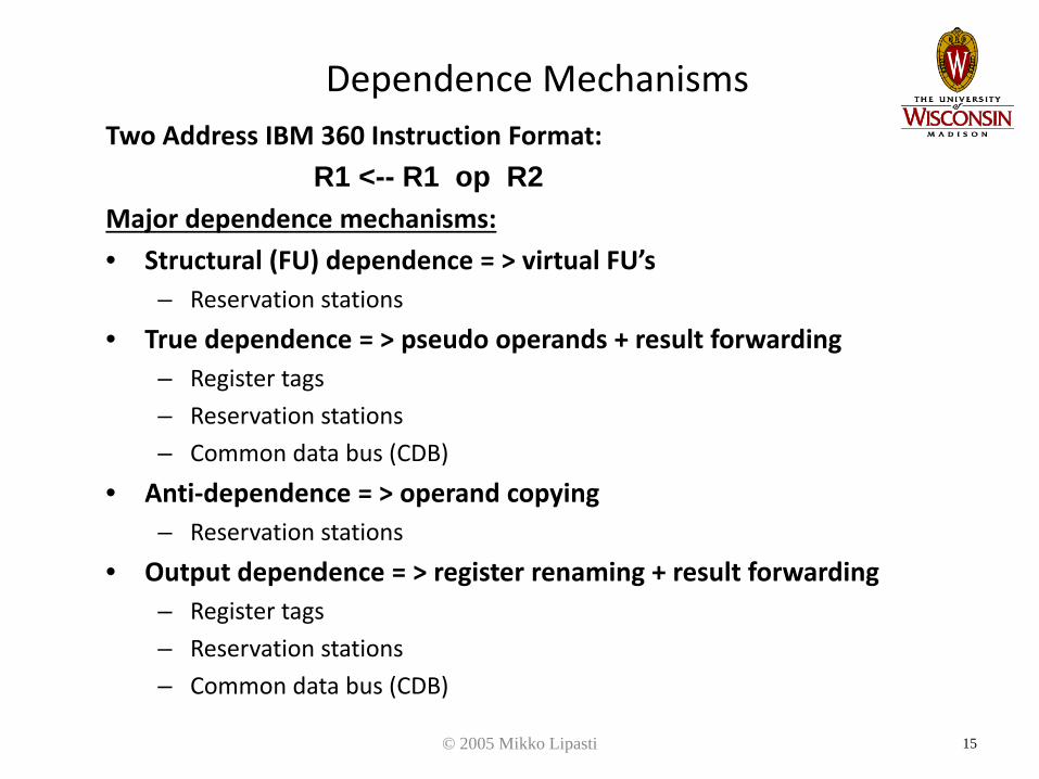
Dependence MechanismsTwo Address IBM 360 Instruction Format:
R1 <-- R1 op R2Major dependence mechanisms:• Structural (FU) dependence = > virtual FU’s
– Reservation stations• True dependence = > pseudo operands + result forwarding
– Register tags– Reservation stations– Common data bus (CDB)
• Anti-dependence = > operand copying– Reservation stations
• Output dependence = > register renaming + result forwarding– Register tags– Reservation stations– Common data bus (CDB)
© 2005 Mikko Lipasti 15

IBM 360/91 FPU
© 2005 Mikko Lipasti 16
Adder
Floating Point
Registers FLR
0
2
4
8
Store
Data
1
2
3
Buffers SDB
Control
Decoder
Floating
Operand
Stack
FLOSControl
Floating Point
Buffers FLB
1
2
3
4
5
6
Decoder
Floating PointRegisters (FLR)
Control
0248
Floating
Operand Stack
Floating PointBuffers (FLB)
123456
StoreData
123
Buffers (SDB)
Control
Storage Bus Instruction Unit
Result
Multiply/Divide
•
Common Data Bus (CDB)
Point
BusyBits
Adder
FLB BusFLR Bus
CDB ••
•
•
Tags
Tags
Sink TagTag Source Ctrl.Sink TagTag Source Ctrl.
Sink TagTag Source Ctrl.Sink TagTag Source Ctrl.Sink TagTag Source Ctrl.
•
Result
(FLOS)

Reservation Stations
• Used to collect operands or pseudo operands (tags).• Associate more than one set of buffering registers (control, source,
sink) with each FU, = > virtual FU’s.• Add unit: three reservation stations• Multiply/divide unit: two reservation stations
Tag Sink Tag Source
0 implies valid data
Source value 0 implies valid data
Source value
© 2005 Mikko Lipasti
17

Common Data Bus (CDB)• CDB is fed by all units that can alter a register (or supply
register values) and it feeds all units which can have a register as an operand.
• Sources of CDB:– Floating-point buffers (FLB)– Two FU’s (add unit and the multiply/divide unit)– 6 FLB + 3 addRS + 2 muldivRS = 11 unique sources– 3 physical sources (FLB, adder, mul/div)
• Destinations of CDB:– Reservation stations– Floating-point registers (FLR)– Store data buffers (SDB)– (5 RS x 2) + 4 FLR + 3 SDB : CDB has 17 destinations
• Circuit design very challenging– 3 physical sources must arbitrate for access to CDB– Tag + data must be driven to 17 destinations
© 2005 Mikko Lipasti 18

Register Tags
• Every source of a register value must be uniquely identified by its own tag value.– (6) FLB’s– (5) reservation stations (3 with add unit, 2 with multiply/divide unit)
= = > 4-bit tag is needed to identify the 11 potential sources
• Every destination of a register value must carry a tag field.– (5) “sink” entries of the reservation stations– (5) “source” entries of the reservation stations– (4) FLR’s– (3) SDB’s
= = > a total of 17 tag fields are needed (i.e. 17 places that need tags)
© 2005 Mikko Lipasti 19
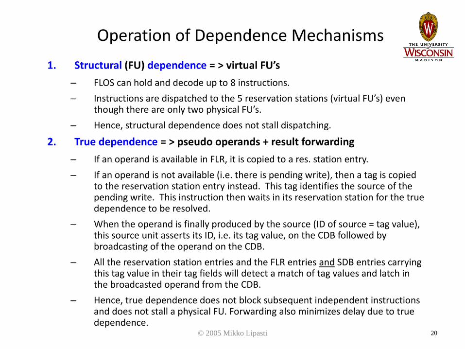
Operation of Dependence Mechanisms1. Structural (FU) dependence = > virtual FU’s
– FLOS can hold and decode up to 8 instructions.– Instructions are dispatched to the 5 reservation stations (virtual FU’s) even
though there are only two physical FU’s.– Hence, structural dependence does not stall dispatching.
2. True dependence = > pseudo operands + result forwarding– If an operand is available in FLR, it is copied to a res. station entry.– If an operand is not available (i.e. there is pending write), then a tag is copied
to the reservation station entry instead. This tag identifies the source of the pending write. This instruction then waits in its reservation station for the true dependence to be resolved.
– When the operand is finally produced by the source (ID of source = tag value), this source unit asserts its ID, i.e. its tag value, on the CDB followed by broadcasting of the operand on the CDB.
– All the reservation station entries and the FLR entries and SDB entries carrying this tag value in their tag fields will detect a match of tag values and latch in the broadcasted operand from the CDB.
– Hence, true dependence does not block subsequent independent instructions and does not stall a physical FU. Forwarding also minimizes delay due to true dependence.
© 2005 Mikko Lipasti 20

Example 1Cycle #1 DISPATCHED INSTRUCTION(S): i
ID Tag Sink Tag Source ID Tag Sink Tag Source Busy Tag Datai 1 0 6.0 0 10.0 4 0 6.0
2 5 2 x 1 3.53 Mult/Div 4 10.0
Adder i 8 7.8
Cycle #2 DISPATCHED INSTRUCTION(S): jID Tag Sink Tag Source ID Tag Sink Tag Source Busy Tag Data
i 1 0 6.0 0 10.0 4 0 6.0j 2 0 6.0 1 5 2 1
3 Mult/Div 4 10.0Adder i 8 x 2 7.8
Cycle #3 DISPATCHED INSTRUCTION(S):ID Tag Sink Tag Source ID Tag Sink Tag Source Busy Tag Data
1 4 0 6.0j 2 0 6.0 0 16.0 5 2 16.0
3 Mult/Div 4 10.0Adder j 8 x 2 7.8
© 2005 Mikko Lipasti
i: R2 <= R0 + R4j: R8 <= R0 + R2 (RAW on R2)
16.0 16.0x

Operation of Dependence Mechanisms
3. Anti-dependence = > operand copying
– If an operand is available in FLR, it is copied to a reservation station entry.
– By copying this operand to the reservation station, all anti-dependences due to future writes to this same register are resolved.
– Hence, the reading of an operand is not delayed, possibly due to other dependences, and subsequent writes are also not delayed.
© 2005 Mikko Lipasti 22

Example 2Cycle #1 DISPATCHED INSTRUCTION(S): i, j
ID Tag Sink Tag Source ID Tag Sink Tag Source Busy Tag Data1 i 4 0 6.0 0 7.8 0 x 5 6.02 j 5 4 0 3.5 2 3.53 Mult/Div i 4 x 4 10.0
Adder 8 7.8
Cycle #2 DISPATCHED INSTRUCTION(S): kID Tag Sink Tag Source ID Tag Sink Tag Source Busy Tag Data
k 1 0 3.5 0 7.8 i 4 0 6.0 0 7.8 0 x 5 6.02 j 5 4 0 3.5 2 x 1 3.53 Mult/Div i 4 x 4 10.0
Adder k 8 7.8
Cycle #3 DISPATCHED INSTRUCTION(S):ID Tag Sink Tag Source ID Tag Sink Tag Source Busy Tag Data
k 1 0 3.5 0 7.8 i 4 0 6.0 0 7.8 0 x 5 6.02 j 5 4 0 3.5 2 x 1 3.53 Mult/Div i 4 x 4 10.0
Adder k 8 7.8
© 2005 Mikko Lipasti
i: R4 <= R0 * R8j: R0 <= R4 * R2 (RAW on R4)k: R2 <= R2 + R8 (WAR on R2)
Operation of Dependence Mechanisms
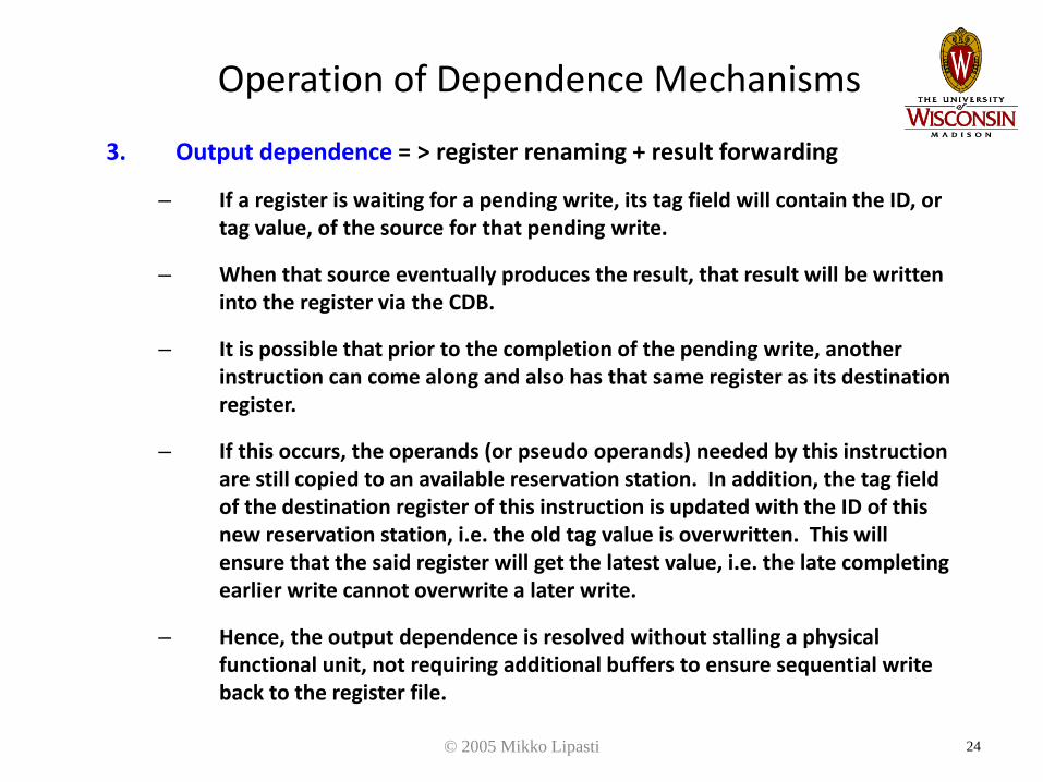
3. Output dependence = > register renaming + result forwarding
– If a register is waiting for a pending write, its tag field will contain the ID, or tag value, of the source for that pending write.
– When that source eventually produces the result, that result will be written into the register via the CDB.
– It is possible that prior to the completion of the pending write, another instruction can come along and also has that same register as its destination register.
– If this occurs, the operands (or pseudo operands) needed by this instruction are still copied to an available reservation station. In addition, the tag field of the destination register of this instruction is updated with the ID of this new reservation station, i.e. the old tag value is overwritten. This will ensure that the said register will get the latest value, i.e. the late completing earlier write cannot overwrite a later write.
– Hence, the output dependence is resolved without stalling a physical functional unit, not requiring additional buffers to ensure sequential write back to the register file.
© 2005 Mikko Lipasti 24

Example 3Cycle #1 DISPATCHED INSTRUCTION(S): i, j
ID Tag Sink Tag Source ID Tag Sink Tag Source Busy Tag Dataj 1 0 6.0 4 i 4 0 6.0 0 7.8 0 6.0
2 5 2 x 1 3.53 Mult/Div i 4 x 4 10.0
Adder 8 7.8
Cycle #2 DISPATCHED INSTRUCTION(S): k, lID Tag Sink Tag Source ID Tag Sink Tag Source Busy Tag Data
j 1 0 6.0 4 i 4 0 6.0 0 7.8 0 6.0k 2 0 6.0 0 7.8 l 5 2 0 7.8 2 x 1 3.5
3 Mult/Div i 4 x 2 10.0Adder k 8 x 5 7.8
Cycle #3 DISPATCHED INSTRUCTION(S):ID Tag Sink Tag Source ID Tag Sink Tag Source Busy Tag Data
j 1 0 6.0 4 i 4 0 6.0 0 7.8 0 6.0k 2 0 6.0 0 7.8 l 5 2 0 7.8 2 x 1 3.5
3 Mult/Div i 4 x 2Adder k 8 7.8
© 2005 Mikko Lipasti
i: R4 <= R0 * R8j: R2 <= R0 + R4 (RAW on R4)k: R4 <= R0 + R8 (WAW on R4)l: R8 <= R4 * R8 (RAW on R4)
What if j causes FP overflow exception?- where is R4?- it is lost => imprecise exceptions!
13.8

Summary of Tomasulo’s Algorithm• Supports out of order execution of instructions.
• Resolves dependences dynamically using hardware.
• Attempts to delay the resolution of dependencies as late as possible.
• Structural dependence does not stall issuing; virtual FU’s in the form of reservation stations are used.
• Output dependence does not stall issuing; copying of old tag to reservation station and updating of tag field of the register with pending write with the new tag.
• True dependence with a pending write operand does not stall the reading of operands; pseudo operand (tag) is copied to reservation station.
• Anti-dependence does not stall write back; earlier copying of operand awaiting read to the reservation station.
• Can support sequence of multiple output dependences.
• Forwarding from FU’s to reservation stations bypasses the register file.

Tomasulo vs. Modern OOOIBM 360/91 Modern
Width Peak IPC = 1 4+Structural hazards 2 FPU
Single CDBMany FUMany busses
Anti-dependences Operand copy Reg. RenamingOutput dependences
Renamed reg. tag Reg. renaming
True dependences Tag-based forw. Tag-based forw.Exceptions Imprecise Precise (ROB)Implementation 3 x 66” x 15” x 78”
60ns cycle time11-12 gate delays per pipe stage>$1 million
< 1 chip300ps< $100

Example 4
i: R4 <-- R0 + R8
j: R2 <-- R0 * R4
k: R4 <-- R4 + R8
l: R8 <-- R4 * R2

Example 4
(2)
(3)
(2)
(3)
(10)
(2)
(3) (2)
(3)
(8)
i
j
k
l
i
j k
l
Can Tomasulo’s algorithm reach dataflow limit of 8?

Example 4
Adder
Tag Sink Tag Source
Mult/Div
Tag Sink Tag Source BusyTag DataID ID
23
1 45
DISPATCHED INSTRUCTION(S): ______________
6.00248
3.510.07.8
CYCLE #1
CYCLE #2
Adder
Tag Sink Tag Source
Mult/Div
Tag Sink Tag Source BusyTag DataID ID
23
1 45
DISPATCHED INSTRUCTION(S): ______________
0248
CYCLE #3
Adder
Tag Sink Tag Source
Mult/Div
Tag Sink Tag Source BusyTag DataID ID
23
1 45
DISPATCHED INSTRUCTION(S): ______________
0248

Example 4CYCLE #4
CYCLE #5
Adder
Tag Sink Tag Source
Mult/Div
Tag Sink Tag Source BusyTag DataID ID
23
1 45
DISPATCHED INSTRUCTION(S): ______________
0248
CYCLE #6
Adder
Tag Sink Tag Source
Mult/Div
Tag Sink Tag Source BusyTag DataID ID
23
1 45
DISPATCHED INSTRUCTION(S): ______________
0248
Adder
Tag Sink Tag Source
Mult/Div
Tag Sink Tag Source BusyTag DataID ID
23
1 45
DISPATCHED INSTRUCTION(S): ______________
0248
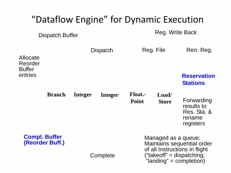
“Dataflow Engine” for Dynamic ExecutionDispatch Buffer
Reservation
Dispatch
Complete
Stations
Compl. Buffer
Branch
Reg. File Ren. Reg.
Forwardingresults toRes. Sta. &
AllocateReorderBufferentries
Reg. Write Back
rename
Managed as a queue;Maintains sequential orderof all Instructions in flight(“takeoff” = dispatching; “landing” = completion)
(Reorder Buff.)
Integer Integer Float.- Load/Point Store
registers

Instruction Processing Steps•DISPATCH:
•Read operands from Register File (RF) and/or Rename Buffers (RRB)
•Rename destination register and allocate RRB entry
•Allocate Reorder Buffer (ROB) entry
•Advance instruction to appropriate Reservation Station (RS)
•EXECUTE:
•RS entry monitors bus for register Tag(s) to latch in pending operand(s)
•When all operands ready, issue instruction into Functional Unit (FU) and deallocate RS entry (no further stalling in execution pipe)
•When execution finishes, broadcast result to waiting RS entries, RRB entry, and ROB entry
•COMPLETE:
•Update architected register from RRB entry, deallocate RRB entry, and if it is a store instruction, advance it to Store Buffer
•Deallocate ROB entry and instruction is considered architecturally completed

Reservation Station Implementation
• Reservation Stations: distributed vs. centralized– Wakeup: benefit to partition across data types– Select: much easier with partitioned scheme
• Select 1 of n/4 vs. 4 of n
Reorder Buffer
ReservationStations
or Issue Queue
In Order In Order
Issue Out of Order
FinishOut of Order

Reorder Buffer Implementation
• Merge RS and ROB => Register Update Unit (RUU)– Inefficient, hard to scale– Perhaps of interest only to historians
Reorder Buffer
RegisterUpdate
Unit
In Order In Order
IssueOut of Order
FinishOut of Order

Scheduling loop• Wakeup dominated by wire delay
– More compact RS => higher frequency
== == OROR
readyL tagL readyRtagR
== == OROR
readyL tagL readyRtagR
tag W tag 1…
… …
ready - requestrequest n
grant n
grant 0request 0
grant 1request 1
……
selected
issueto FU
broadcast the tagof the selected inst
Select logic Wakeup logic
schedulingloop
Mikko Lipasti-University of Wisconsin 36

Scheduler Designs• Data-Capture Scheduler
– keep the most recent register value in reservation stations
– Data forwarding and wakeup are combined
RegisterFile
Data-capturedscheduling window(reservation station)
Functional Units
Forw
ardi
ngan
d w
akeu
p Reg
iste
r upd
ate
Mikko Lipasti-University of Wisconsin 37

Scheduler Designs• Non-Data-Capture
Scheduler– keep the most recent
register value in RF (physical registers)
– Data forwarding and wakeup are decoupled
RegisterFile
Non-data-capturescheduling
window
Functional Units
Forw
ardi
ng
wak
eup
Complexity benefits smaller RS / faster wakeup path
Mikko Lipasti-University of Wisconsin 38

Mapping to pipeline stages• AMD K7 (data-capture)
Pentium 4 (non-data-capture)
Data
Data
Data / wakeup
wakeup
Mikko Lipasti-University of Wisconsin 39
Scheduling atomicity & non-data-capture scheduler
Fetch Decode Sched/Exe Writeback Commit
Atomic Sched/Exe
Fetch Decode Schedule Dispatch RF Exe Writeback Commit
wakeup/select
Fetch Decode Schedule Dispatch RF Exe Writeback CommitFetch Decode Schedule Dispatch RF Exe Writeback CommitFetch Decode Schedule Dispatch RF Exe Writeback CommitFetch Decode Schedule Dispatch RF Exe Writeback CommitFetch Decode Schedule Dispatch RF Exe Writeback Commit
Wakeup/Select
Fetch Decode Schedule Dispatch RF Exe Writeback Commit
Wakeup/Select
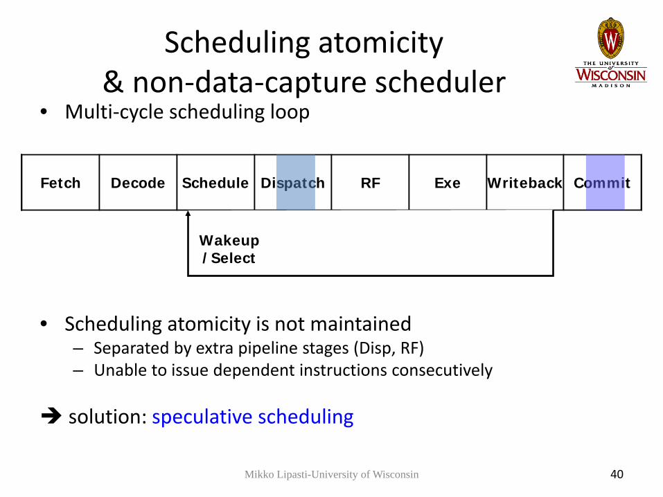
• Multi-cycle scheduling loop
• Scheduling atomicity is not maintained– Separated by extra pipeline stages (Disp, RF)– Unable to issue dependent instructions consecutively
solution: speculative scheduling
Mikko Lipasti-University of Wisconsin 40

Speculative Scheduling• Speculatively wakeup dependent instructions even before the parent
instruction starts execution– Keep the scheduling loop within a single clock cycle
• But, nobody knows what will happen in the future
• Source of uncertainty in instruction scheduling: loads– Cache hit / miss– Store-to-load aliasing eventually affects timing decisions
• Scheduler assumes that all types of instructions have pre-determined fixed latencies– Load instructions are assumed to have a common case (over 90% in general)
$DL1 hit latency– If incorrect, subsequent (dependent) instructions are replayed
Mikko Lipasti-University of Wisconsin 41

Speculative Scheduling• Overview
Spec wakeup/select
Fetch Decode Schedule Dispatch RF Exe Writeback/Recover Commit
Speculatively issued instructions
Re-schedulewhen latency mispredicted
Fetch Decode Schedule Dispatch RF Exe Writeback/Recover Commit
Speculatively issued instructions
Re-schedulewhen latency mispredicted
Spec wakeup/select
Fetch Decode Schedule Dispatch RF Exe Writeback/Recover Commit
Speculatively issued instructions
Re-schedulewhen latency mispredicted
Fetch Decode Schedule Dispatch RF Exe Writeback/Recover Commit
Speculatively issued instructions
Re-schedulewhen latency mispredicted
Fetch Decode Schedule Dispatch RF Exe Writeback/Recover Commit
Speculatively issued instructions
Re-schedulewhen latency mispredicted
Fetch Decode Schedule Dispatch RF Exe Writeback/Recover Commit
Speculatively issued instructions
Re-schedulewhen latency mispredicted
Fetch Decode Schedule Dispatch RF Exe Writeback/Recover Commit
Speculatively issued instructions
Re-schedulewhen latency mispredicted
Latency Changed!!
Fetch Decode Schedule Dispatch RF Exe Writeback/Recover Commit
Re-schedulewhen latency mispredicted
Invalid input value
Speculatively issued instructions
Fetch Decode Schedule Dispatch RF Exe Writeback/Recover Commit
Speculatively issued instructions
Unlike the original Tomasulo’s algorithm Instructions are scheduled BEFORE actual execution occurs Assumes instructions have pre-determined fixed latencies
ALU operations: fixed latency Load operations: assumes $DL1 latency (common case)
Mikko Lipasti-University of Wisconsin 42

Selection Logic• Single FU of each type: arbiter
– Choose 1:n ready instructions– Fairly straightforward logic
• Multiple FUs of a given type: allocator– Choose m:n ready instructions– Must solve classic “matching” problem
• Using e.g. iSLIP [Mckeown, IEEE Trans. On Networking, 1999]
– Not feasible in cycle-time critical loop– Instead: instructions bound to FU when inserted
Mikko Lipasti-University of Wisconsin 43

Selection Logic• Arbiter must guarantee forward progress
– Select oldest instruction first– Algorithm: mask remembers who was waiting
when you arrived, defer to them
Mikko Lipasti-University of Wisconsin 44
0
Entry
0
Valid
0000
Mask
1 0 0000
2 0 0000
3 0 00001
1101
1 0000
0100
1
1 0101
1) Entries 2 & 3 wake up: 00112: |(0011 & 1101) => true3: |(0011 & 0100) => false
2) 3 is selected, flash clears col 3
0 0000
0100
1100
3) 2 is selected in next cycle, etc.

Reorder Buffer Implementation
• Reorder Buffer– “Bookkeeping,” physically distributed, many read/write ports
– Can be instruction-grained, or block-grained (4-5 ops)
Mikko Lipasti-University of Wisconsin 45

Register File Speculation & Recovery• History file (similar to checkpointing)
– Copy previous value from ARF to HF at dispatch
– Use HF to reconstruct precise state if needed
• Future file: separate ARF & RRF (lecture notes, PPC 620, Pentium Pro, Core i7, AMD K8, ARM A15)– Copy committed value from RRF to ARF– Update rename table mapping
• Physical Register File: merged ARF & RRF (MIPS R10000 , Pentium 4, Alpha 21264, Power 4-7, Nehalem, Sandybridge, Bulldozer, Bobcat)– No copy; simpler datapath (operand always in PRF)– Simply “commit” rename table mapping as branches resolve
Mikko Lipasti-University of Wisconsin 46

Register File Alternatives
• Rename register organization– Future file (future updates buffered, later committed)
• Rename register file– History file (old versions buffered, later discarded)– Merged (single physical register file)
Register Lifetime Status
Duration(cycles)
Result stored where?
Future File History File Phys. RF
Dispatch Unavail ≥ 1 N/A N/A N/A
Finish execution
Speculative ≥ 0 FF ARF PRF
Commit Committed ≥ 0 ARF ARF PRF
Next def. Dispatched
Committed ≥ 1 ARF HF PRF
Next def. Committed
Discarded ≥ 0 Overwritten Discarded Reclaimed
Mikko Lipasti-University of Wisconsin 47

ARF vs. PRF
Architected Register File -style
RAT
ARF ROB
RS
Payload RAM
Bypass
ALU
We showed that PRF is better [ISLPED 07] – nearly everyone now agrees! P6 thru Core 2 Duo (Merom): ARF Pentium4/Nehalem/Sandybridge, AMD Bulldozer & Bobcat: PRF Recent regression: Intel Silvermont, Cortex A15 use ARF … design team?
RAT
ROB
RS
PRF
Bypass
ALU
Physical Register File - style
Mikko Lipasti-University of Wisconsin 48

Misprediction Recovery
Branch mispredicts, exceptions: must reclaim allocated resources Load queue, store queue/color, branch color, ROB entry, rename register
Can reclaim implicitly Tag broadcast: all entities match & release Too expensive for physical register file (PRF)
Or reclaim explicitly Walk through ROB which contains pointers Follow pointers to release resources
Also, recover rename mappings Read previous mappings (pending release) and repair map table
Valid PC DestPR
PrevPR
Src1 Src2 Imm/target
Issued Executed Exception T/NT Pred
1 x400C P13 P17 P25 n/a X80 Y Y N
1 X4008 P14 P22 P31 P5 Y N N
1 X4004 x4020 NT
Mikko Lipasti-University of Wisconsin 49

Rename Table Implementation
• MAP checkpointing– Performance optimization
• Recovery from branches, exceptions
– Checkpoint granularity• Every instruction (costly)• Every branch, play back ROB to get to exception
boundary
• RAM vs CAM Map Table
Mikko Lipasti-University of Wisconsin 50
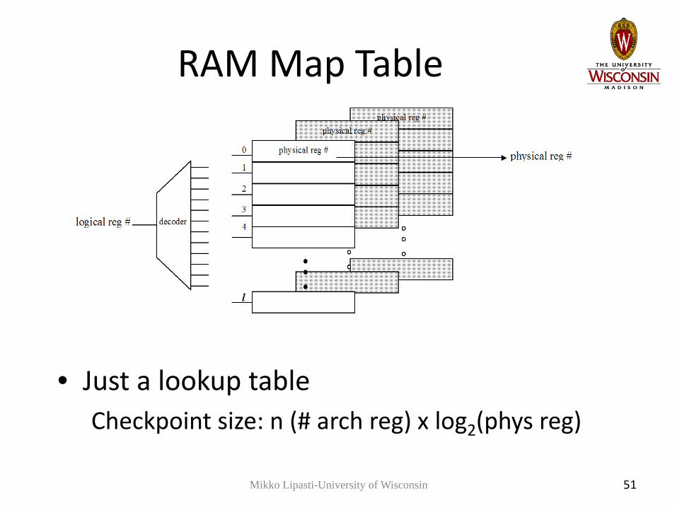
RAM Map Table
• Just a lookup tableCheckpoint size: n (# arch reg) x log2(phys reg)
Mikko Lipasti-University of Wisconsin 51

CAM Map Table
• CAM search for mappings– # rows == number of physical registers– Checkpoint only the valid bit column
• Used in Alpha 21264Mikko Lipasti-University of Wisconsin 52

Summary• Register dependences
– True dependences– Antidependences– Output dependences
• Register Renaming• Tomasulo’s Algorithm• Reservation Station Implementation• Reorder Buffer Implementation• Register File Implementation
– History file– Future file– Physical register file
• Rename Table Implementation