registr ation techniques for using imperf ect and p ar
TRANSCRIPT
Registration Techniques for Using Imperfect and PartiallyCalibrated Devices in Planar Multi-Projector Displays
Ezekiel Bhasker, Ray Juang, Student, IEEE, and Aditi Majumder, Member, IEEE
Abstract— Multi-projector displays today are automatically registered, both geometrically and photometrically, using cameras. Exist-ing registration techniques assume pre-calibrated projectors and cameras that are devoid of imperfections such as lens distortion. Inpractice, however, these devices are usually imperfect and uncalibrated. Registration of each of these devices is often more challeng-ing than the multi-projector display registration itself. To make tiled projection-based displays accessible to a layman user we shouldallow the use of uncalibrated inexpensive devices that are prone to imperfections. In this paper, we make two important advancesin this direction. First, we present a new geometric registration technique that can achieve geometric alignment in the presence ofsevere projector lens distortion using a relatively inexpensive low-resolution camera. This is achieved via a closed-form model thatrelates the projectors to cameras, in planar multi-projector displays, using rational Bezier patches. This enables us to geometricallycalibrate a 3000× 2500 resolution planar multi-projector display made of 3× 3 array of nine severely distorted projectors using a lowresolution (640× 480) VGA camera. Second, we present a photometric self-calibration technique for a projector-camera pair. Thisallows us to photometrically calibrate the same display made of nine projectors using a photometrically uncalibrated camera. To thebest of our knowledge, this is the first work that allows geometrically imperfect projectors and photometrically uncalibrated camerasin calibrating multi-projector displays.
Index Terms—Geometric calibration, photometric calibration, tiled displays.
1 INTRODUCTION
Multi-projector displays are popular today for many applications suchas visualization, entertainment, training, and simulation. Contem-porary researchers envision future workspaces with ubiquitous pixelsrendered by multi-projector displays of various scales and forms aid-ing users in collaboration, interface, and visualization [9, 12, 16, 17,24, 25, 30, 33, 36].
To enable such readily accessible multi-projector displays, auto-mated camera-based registration techniques that register the imagerycoming from multiple projectors, both geometrically and photomet-rically, have been proposed [5, 6, 13, 19, 20, 21, 23, 26, 27, 28, 29,34, 37, 38]. More recently, Bhasker, et al. [2], proposed a distributednetwork of compact projector-camera units that can self-register with-out any user input, relieving the user of installation and maintenanceresponsibilities. However, all these methods do not handle imperfec-tions, such as lens distortions, that are common in inexpensive com-modity devices. They assume pre-calibrated devices (i.e., deviceswhose geometric and photometric parameters are known) leaving theresponsibility of device calibration to the user. Device calibration is of-ten more challenging than multi-projector display registration and de-mands a very educated user. This difficulty in deployment has quaran-tined tiled projection-based displays to national laboratories and uni-versities despite huge advances in automated camera-based registra-tion techniques.
The work in this paper makes initial advances by developing ge-ometric and photometric registration techniques that allow imperfectuncalibrated devices to be used for the most common cases of planardisplays. The ultimate goal would be to allow the use of projectorswith severe geometric and photometric distortion and still achieve ac-ceptable geometric and photometric registration. We achieve this goal
• Ezekiel Bhasker is with University of California, Irvine, E-mail:[email protected].
• Ray Juang is with University of California, Irvine, E-mail:[email protected].
• Aditi Majumder is with University of California, Irvine, E-mail:[email protected].
Manuscript received 31 March 2007; accepted 1 August 2007; posted online27 October 2007.For information on obtaining reprints of this article, please send e-mail to:[email protected].
using cameras that are neither geometrically nor photometrically reg-istered. The paper by Majumder and Stevens [21] is the only workto date in this direction and presents initial methods to handle largespatial variation in intensity within and across projectors. In this pa-per, we make further advances to these unexplored domains. Theseare: (a) achieving geometric registration while using projectors thathave considerable geometric imperfections (e.g., lens distortions); (b)achieving photometric registration with a photometrically uncalibratedcamera.
1.1 Using Geometrically Imperfect ProjectorsWe present a new geometric registration technique that can correct forsevere lens distortion using a relatively low-resolution camera for pla-nar multi-projector displays. This method relies on a new parametricgeometric model relating the projector to the camera used for register-ing the display. The relationship is modeled in a compact and efficientmanner using a rational Bezier patch.
Projection technology is advancing at a tremendous pace. Pocketprojectors that can fit on one’s palm are no longer a myth but a re-ality [1]. Industry initiatives are finding ways to build short-throw,unbreakable projectors that use LEDs as light sources so that they canbe embedded in cell phones. It is evident that lens distortion will besignificant in such low-cost projectors. Our method will enable the useof such low-cost projectors to build commodity tiled displays.
Further, in designing a compact multi-projector display or changingan existing setup to increase space utility, a short-throw lens is requiredto decrease the throw distance of the projectors. These lenses currentlyrequire several optical elements to reverse the high lens distortion cre-ated by short focal lengths. Hence, they are cost-prohibitive (around$2000 - $6000) and at least 5-6 times the cost of regular projectors(around $800 - $1500). Our work handles severe lens distortions, thuspaving the way for using inexpensive lenses on projectors, just as theyare used on cameras today. This allows for even more compact multi-projector display designs.
1.2 Using Photometrically Uncalibrated CamerasExisting methods for photometric calibration of a multi-projector dis-play often use a camera that is first calibrated using high dynamicrange images [8, 26]. This involves taking images in an outdoor envi-ronment where one does not have control of motion, illumination, etc.This calibrated camera is then used to recover the photometric proper-

ties of the projectors which are then modified appropriately to achievea photometrically seamless multi-projector display [21, 26].
In this paper, we present a photometric self-calibration techniquefor a projector-camera pair that allows us to register a multi-projectordisplay photometrically using an uncalibrated camera. To the best ofour knowledge, this is the first work that estimates both the intensitytransfer function and the spatial variation in intensity of projectors si-multaneously using a photometrically uncalibrated camera.
2 RELATED WORK
In this section, we review existing geometric and photometric regis-tration techniques and relate them to the techniques we present in thispaper.
2.1 Geometric RegistrationGeometric registration of planar multi-projector displays entails re-constructing two functions: (a) the function that relates the individualprojector coordinates to the camera coordinates; and (b) the functionthat relates the camera coordinates to the global screen coordinates.Most geometric registration techniques devised for planar displays sofar fall into the following categories.
Linear methods assume linear models for cameras and projectors.They relate the projector, camera, and the screen coordinates by lin-ear matrices called homographies [5, 34]. However, linear models donot account for geometric non-linearities, such as lens distortion, andcannot achieve accurate alignment in their presence. To achieve ac-ceptable alignment in such cases, projectors are manually adjusted tothe ‘sweet-spot’ in zoom level where the non-linear distortions becomenegligible.
Piecewise linear methods address these geometric non-linearitiesby using a piecewise linear function, essentially a triangulation, torelate the projector, camera and screen coordinates to each other.Though this achieves reasonable geometric accuracy, a dense trian-gulation is required to sample the parameter space adequately [37].Thus, a high-resolution (5-6 Megapixel) camera is required to registereven relatively small displays made of 4-6 projectors.
Hereld, et. al. [13], use a non-linear model where a closed-formcubic function handles some of the geometric non-linearities. Thismethod has two limitations. First, a simple cubic polynomial cannotcapture the perspective projection between the projector and the cam-era adequately. As a result, this method assumes a close-to-rectangulararray of projectors resulting from on-axis projection. Such an arrange-ment is relatively easy to achieve manually in a rear-projection system,but not in front-projection system where the projector is on the ceilingprojecting on a screen placed on the ground. Second, this work is notmotivated by accurate analysis of the kind of non-linearities seen inprojectors and hence cannot handle higher order non-linearities.
Our method incorporates the non-linear distortions of the projec-tor into the function that relates the projector to other entities, such asthe camera and screen, using a single accurate closed-form function– the rational Bezier patch. This allows combination of distortionsarising from completely different reasons (e.g., lens distortion and key-stoning) into a single unified representation. Further, it results in an ef-ficient camera-based geometric registration for planar, multi-projectordisplays, that can handle significant lens distortion.
2.2 Photometric RegistrationPhotometric properties of a camera/projector involve its intensitytransfer function, or ITF (more commonly called the gamma function),and the spatial intensity fall-off in its field-of-view (more commonlycalled the vignetting effect). Photometric registration of projection-based displays requires estimation of the photometric properties of theprojectors using a camera. To do this, the camera is first photometri-cally registered. The high dynamic range imaging technique [8, 22]can be used to estimate the camera’s ITF by taking images outdoors.Currently, there is no simple automated way of estimating the cam-era’s vignetting effect. The registered camera is usually set to a nar-row aperture when using it to estimate the photometric properties ofthe projectors in a tiled display. The techniques in the work by Raij,
et al. [26], are then applied to estimate the projectors’ ITF using theregistered camera. Using the projectors with known ITF, the tech-niques described in the papers by Majumder and Stevens [20, 21] arethen used to estimate the spatial intensity fall-off of the projector, andto register the multiple projectors photometrically using the estimatedphotometric properties. No method currently exists that can use a pho-tometrically uncalibrated camera and recover both the ITF and the spa-tial intensity fall-off of the projectors simultaneously. Our method inthis paper estimates all the different photometric parameters of bothdevices in a photometrically uncalibrated projector-camera pair. It isaccomplished in a controlled indoor setting without using any otherphysical props. Photometric registration techniques that use these pa-rameters [20, 21, 38] can then be utilized to achieve photometric seam-lessness in the multi-projector display.
3 USING GEOMETRICALLY IMPERFECT PROJECTORS
In this section, we present our geometric registration technique thatcorrects for projector geometric imperfections, such as lens distortion.We use a camera that is corrected for lens distortion [3]. First, we de-velop a new model that relates a single projector to the camera in aplanar multi-projector display using a rational Bezier patch. The pro-jector lens distortion is modeled by an affine-invariant non-rationalBezier patch. For a projector-camera setup with a planar display, thisfunction is followed by a homography that relates the projector to thecamera and to the screen linearly. We use a perspective-invariant ratio-nal Bezier patch to model the combination of these non-linear and lin-ear functions. Thus, all the different distortions in a planar projection-based display (e.g., key-stoning, radial, and tangential distortions) arecombined into a single closed-form function. To the best of our knowl-edge, this is the first work that models both linear and non-linear dis-tortions of a projector-camera system in a unified manner.
To geometrically register multiple distorted projectors, we sparselysample the rational Bezier function relating the projector coordinateswith the camera and screen coordinates, and estimate the function pa-rameters. These parameters are then used to warp the input image tothe projector appropriately resulting in a geometrically aligned image.The sparse sampling proves adequate for acceptable geometric regis-tration since the rational Bezier offers a piecewise curve representa-tion (which is more suited for lens distortions that transform lines tocurves), rather than a piecewise linear representation. This sparse sam-pling allows us to use a low-resolution camera to achieve geometricregistration for even medium sized displays made of 6-16 projectors.
3.1 Model for Single ProjectorWe first consider the simple case of a single projector projecting ontoa planar screen and being observed by a single camera corrected forlens distortion. Our goal is to design an accurate parametric functionF that defines the relationship between the projector pixels (x,y) andthe camera pixels (u,v), i.e., (u,v) = F (x,y). Ideally, the functionF has two components. The first is the lens distortion function Rthat relates the undistorted projector coordinates (x,y) to the distortedcoordinates on the display screen (xd ,yd). The second component isthe well-known homography H that relates the distorted coordinatesto camera coordinates (u,v).
(u,v) = H (xd ,yd) = H (R(x,y)) = F (x,y) (1)
We would like to model F by a single compact parametric functionthat accurately captures the effect of the concatenation of these twofunctions, H and R, and is amenable to efficient data fitting compu-tation.
Modeling R with Non-rational Bezier Patches: The classic lensdistortion model [4, 10] consists of two independent distortions: radialdistortion (e.g., barrel or pin-cushion) and tangential distortion.
Radial distortion is usually modeled by
xd = x+(x− xp)(k1r2 + k2r4 + k3r6) = x+ρx, (2)
yd = y+(y− yp)(k1r2 + k2r4 + k3r6) = y+ρy, (3)

Case No. Lens Distortion Parameters % Error ForCenter Radial Tangential Bezier of degree(xc,yc) (k1,k2,k3) (p1, p2) 2 3 4 5 6 7
(a) (0.5,0.5) (−0.35,0,0) (0,0) 5.78 ε(b) (0.5,0.5) (0,0,0) (0.1,0.1) ε(c) (0.5,0.5) (−0.35,−0.35,0) (0,0) 9.00 0.91 0.56 ε(d) (0.6,0.55) (−0.35,−0.13,0) (0.05,0.05) 1.9 0.14 0.03 ε(e) (0.6,0.55) (−0.35,−0.13,−0.016) (0.05,0.05) 2.0 0.17 0.038 0.0012 0.00022 ε
Table 1. This table shows the accuracy of our fit for lens distortion functions using non-rational Bezier patches of different degree. Due to the largenumber of lower degree terms, note that in case (e) distortion of higher degrees (e.g., degree 7) can be fitted to reasonable accuracy by a lowerdegree Bezier (e.g., degree 4). ε represents the convergence threshold used which is strictly less than 10−11.
(a) (b) (c) (d) (e)
Fig. 1. Images showing the fives cases of distortion mentioned in Table 1.
where (xd ,yd) and (x,y) are the distorted and undistorted image coor-
dinates respectively, r =√
(x− xp)2 +(y− yp)2 is the radial distancefrom the principal center (xp,yp) in the undistorted image, and ki,1≤ i≤ 3 are the radial distortion coefficients. Negative values of ki re-sult in barrel distortion while positive values result in pin-cushioning.The principal center is a point in the image that is unchanged by radialdistortion. In general, the principal center (xp,yp) need not be at thecenter of the image but is usually close to the center.
The tangential distortion is modeled by
xd = x+2p1xy+ p2r2 +2p2x2 = x+ τx, (4)yd = y+2p2xy+ p1r2 +2p1y2 = y+ τy (5)
where r =√
(x− xp)2 +(y− yp)2 and p1 and p2 are the tangentialdistortion parameters.
Radial and tangential distortion are independent of each other andhence their effects can be combined into a comprehensive lens distor-tion equation, as
(xd ,yd) = (x+ρx + τx,y+ρy + τy). (6)
Estimating the unknown radial and tangential distortion coefficientsinvolves solving complex non-linear optimization problems. Hence,several simplifying assumptions are usually made which are often nottrue in a real system. The most common simplifications are to assumethat the principal point coincides with the center of the image and toignore the higher degree terms [3, 7, 15, 32, 35, 39].
We model this lens distortion by non-rational Bezier patches in-stead. A non-rational Bezier patch of degree k and dimension d is de-fined by (k +1)d control points in a d-dimensional space. In our case,we consider a two-dimensional patch where d = 2. The Bezier patchis a tensor product patch where the control points, Pi j, are weighted byblending functions that are products of independent one-dimensionalBernstein polynomials. There are k + 1 Bernstein polynomials of de-gree k given by
bnk(t) =k!
n!(k−n)!tn(1− t)k−n (7)
where 0≤ n≤ k and 0≤ t ≤ 1. The non-rational Bezier patch can thenbe defined from these polynomials as
N B(x,y) =k
∑i=0
k
∑j=0
Pi jbik(x)b jk(y) (8)
=k
∑i=0
k
∑j=0
Pi jBi jk(x,y), (9)
where Bi jk is the tensor product of the Bernstein polynomials bik andb jk and 0 ≤ (x,y) ≤ 1. Hence, in the context of the single projector-camera pair for planar displays, the projector lens distortion functionR(x,y) is represented by
(xd ,yd) = R(x,y) = N B(x,y) (10)
Our choice of using a non-rational Bezier patch is guided by thefollowing rationale.
1. The non-rational Bezier patch provides a unified framework torepresent a large range of lens distortions. More severe lens dis-tortions can be included by increasing the degree of the Bezierpatch. For example, a bicubic Bezier patch may be sufficient forstandard narrow FOV lenses, but a Bezier patch of degree 4 maybe required for the more severe distortions of wide FOV lenses.All of these are handled by the non-rational Bezier patch withoutaffecting the underlying computational framework.
2. When Equation 10 is expanded and compared with Equation6, one finds that the non-rational Bezier patch has many morehigher-order cross terms, making it a more flexible model. Forexample, it is possible for short-throw lens projectors to havea mix of both barrel and pin-cushion distortions. Such cases arebetter handled by a more flexible model such as the Bezier patch.
3. The principal center creates a particular nuisance in traditionallens distortion estimation techniques, and forces most practicalsystems to assume it to be at the center of the image. Whenusing a non-rational Bezier patch, the principle center is encodedwithin the control points themselves, and need not be estimatedseperately.
4. Like lens distortion, non-rational Bezier patches are also affine-invariant and hence provide an accurate model.
Table 1 and Figure 1 present results on the accuracy of our Bezierpatch model. We consider a dense sampling of the (x,y) space, distortit using various traditional lens distortion parameters, and fit a non-rational Bezier patch to the distorted points. To evaluate the accuracyof the fitted Bezier, we find the average Euclidian distance error be-tween fitted and the distorted data as a percentage of the distance from
(a) (b) (c)
(d) (e) (f)
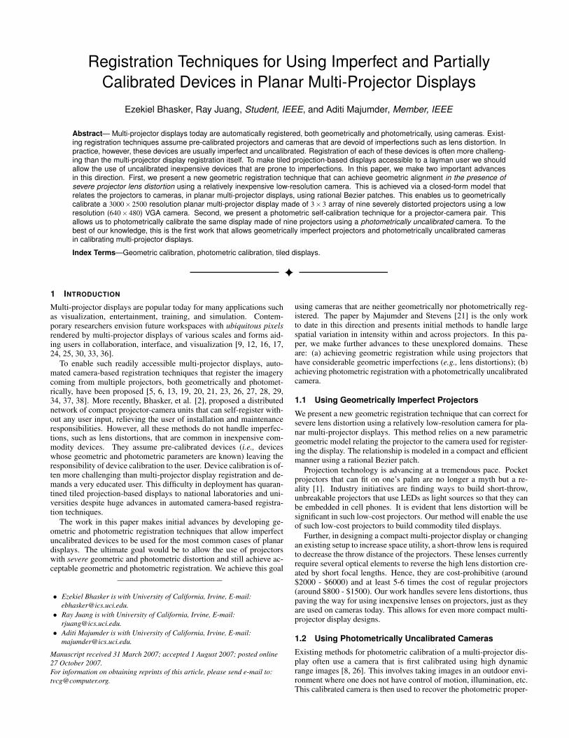
Fig. 2. Results of geometric registration shown on our display which is a 3×3 array of nine projectors. The geometric registration is achieved usingbicubic rational Bezier patches with sparse correspondences (8×6 for a 1024×768 projector). (a, b, c) Before registration; (d, e, f) After registration.The grid image in the last column is made of lines that are one pixel wide. To retain clarity of the grids in the overlap region, photometric registrationis not applied to the grid image in (c) when generating the registered image (f).
the principal center. Note that even when higher order distortions arepresent (e.g., x7), lower degree Bezier patches (e.g., bicubic) can pro-vide a good fit. This is due to the presence of a large number of lower-order cross-terms, which are absent in the traditional lens distortionmodel.
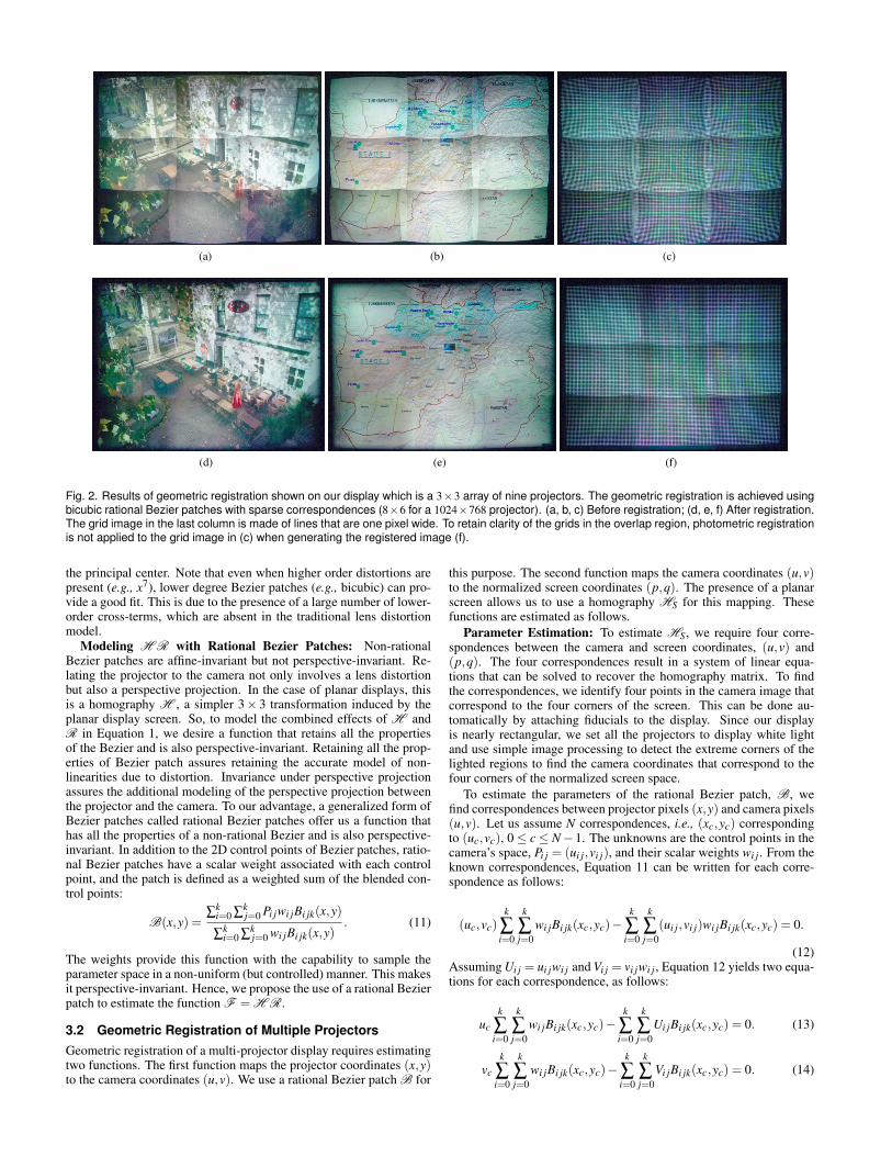
Modeling H R with Rational Bezier Patches: Non-rationalBezier patches are affine-invariant but not perspective-invariant. Re-lating the projector to the camera not only involves a lens distortionbut also a perspective projection. In the case of planar displays, thisis a homography H , a simpler 3× 3 transformation induced by theplanar display screen. So, to model the combined effects of H andR in Equation 1, we desire a function that retains all the propertiesof the Bezier and is also perspective-invariant. Retaining all the prop-erties of Bezier patch assures retaining the accurate model of non-linearities due to distortion. Invariance under perspective projectionassures the additional modeling of the perspective projection betweenthe projector and the camera. To our advantage, a generalized form ofBezier patches called rational Bezier patches offer us a function thathas all the properties of a non-rational Bezier and is also perspective-invariant. In addition to the 2D control points of Bezier patches, ratio-nal Bezier patches have a scalar weight associated with each controlpoint, and the patch is defined as a weighted sum of the blended con-trol points:
B(x,y) =∑k
i=0 ∑kj=0 Pi jwi jBi jk(x,y)
∑ki=0 ∑k
j=0 wi jBi jk(x,y). (11)
The weights provide this function with the capability to sample theparameter space in a non-uniform (but controlled) manner. This makesit perspective-invariant. Hence, we propose the use of a rational Bezierpatch to estimate the function F = H R.
3.2 Geometric Registration of Multiple ProjectorsGeometric registration of a multi-projector display requires estimatingtwo functions. The first function maps the projector coordinates (x,y)to the camera coordinates (u,v). We use a rational Bezier patch B for
this purpose. The second function maps the camera coordinates (u,v)to the normalized screen coordinates (p,q). The presence of a planarscreen allows us to use a homography HS for this mapping. Thesefunctions are estimated as follows.
Parameter Estimation: To estimate HS, we require four corre-spondences between the camera and screen coordinates, (u,v) and(p,q). The four correspondences result in a system of linear equa-tions that can be solved to recover the homography matrix. To findthe correspondences, we identify four points in the camera image thatcorrespond to the four corners of the screen. This can be done au-tomatically by attaching fiducials to the display. Since our displayis nearly rectangular, we set all the projectors to display white lightand use simple image processing to detect the extreme corners of thelighted regions to find the camera coordinates that correspond to thefour corners of the normalized screen space.
To estimate the parameters of the rational Bezier patch, B, wefind correspondences between projector pixels (x,y) and camera pixels(u,v). Let us assume N correspondences, i.e., (xc,yc) correspondingto (uc,vc), 0 ≤ c ≤ N−1. The unknowns are the control points in thecamera’s space, Pi j = (ui j,vi j), and their scalar weights wi j. From theknown correspondences, Equation 11 can be written for each corre-spondence as follows:
(uc,vc)k
∑i=0
k
∑j=0
wi jBi jk(xc,yc)−k
∑i=0
k
∑j=0
(ui j,vi j)wi jBi jk(xc,yc) = 0.
(12)Assuming Ui j = ui jwi j and Vi j = vi jwi j, Equation 12 yields two equa-tions for each correspondence, as follows:
uck
∑i=0
k
∑j=0
wi jBi jk(xc,yc)−k
∑i=0
k
∑j=0
Ui jBi jk(xc,yc) = 0. (13)
vck
∑i=0
k
∑j=0
wi jBi jk(xc,yc)−k
∑i=0
k
∑j=0
Vi jBi jk(xc,yc) = 0. (14)

(a) (b) (c) (d)
(e) (f) (g) (h)
Fig. 3. Geometric registration of projectors with severe barrel distortion: using a linear piecewise method with sparse - 48 samples (a) anddense - 432 samples (b) correspondences; using rational bicubic Bezier patches with sparse - 48 samples (c) and dense - 432 samples (d)correspondences. (e,f,g,h) provides a zoomed in view of the projector overlap regions in (a,b,c,d) respectively. It is evident that piecewise linearmethods with sparse correspondences lead to severe mismatches. The results using rational Bezier are similar, even when the sampling is reducedby an order of magnitude. In fact, at places, the results from using rational Bezier patches with sparse sampling is better than the results from usinga dense sampling for the piecewise linear method. This is evident as the grid lines are thicker in the overlap region in (b) due to slight errors.
The unknowns for estimating a two-dimensional rational Bezier patchof degree k are (k + 1)2 control points and weights, which result in atotal of 3(k + 1)2 unknowns. The weights are variables that dependon the control points in a non-linear fashion. So, the above equationsresult in a non-linear least-squares fitting problem that can be solvedefficiently using the Levenberg-Marquardt gradient descent optimiza-tion technique [31]. As an initial guess to this optimization, we fit thecontrol polygon tightly around the set of correspondences (uc,vc) inthe camera space and constrain the weights to be strictly greater than0.
To find the correspondences between projector and camera coordi-nates, (x,y) and (u,v), we display a rectangular grid of Gaussian blobswith known coordinates on each projector. These are captured by acalibrated camera in a series of non-overlapping images. We use a 2D-stepping procedure that depends on a user to identify the top-left bloband its immediate right and bottom neighbors in camera space. Withthis minimal three point user input, we can design a stepping proce-dure that (a) estimates the rough position of the next blob in scan-lineorder, and (b) searches for the correct blob position using the nearestwindowed center-of-mass technique [11]. If this is not possible formore extreme projector distortions, one can binary-encode the blobsand project them in a time sequential manner to recover the exact idsof the detected blobs and find the correspondences [28, 37].
Image Correction: To create a geometrically seamless and undis-torted display, we warp the image for each projector as follows: Foreach projector coordinate (x,y), we first compute the correspondingcamera coordinate (u,v) using the rational Bezier patch B. Next, wecompute the corresponding normalized screen coordinates (p,q) us-ing the homography HS. The generated coordinates (p,q) are usedas indices into the image being rendered on the tiled display. Bilinearinterpolation is used to assign the final value of each projector pixel.Thus, the correction is achieved by the mapping
(p,q) = HS(u,v) = HS(B(x,y)). (15)
3.3 Implementation and ResultsWe have applied our method on our 8× 6-foot display made of 3× 3array of nine projectors. Our projectors have relatively large throw ra-
tios and hence do not reveal major lens distortions. Instead of choosingthe cost prohibitive option of buying nine short-throw lenses, we choseto simulate the distortion digitally by distorting the input images to theprojectors.
The registration is done offline and takes a couple of minutes. Thisgenerates the parameters of the rational Bezier for each projector,which are then stored to be used during image correction. We haveimplemented the image correction in real-time using modern GPUsthrough Chromium – an open-source distributed rendering engine forPC clusters [14]. A module for Chromium is written that first pre-computes the coordinate-mappings of all pixel coordinates using thestored parameters of the rational Bezier. This results in a per-pixelprojector to screen lookup table. A fragment program for the pixelshader quickly maps pixels from the projector coordinate space to thescreen coordinate space during rendering.
Figure 2 shows the results. The advantage of using an appro-priate parametric function lies in an accurate alignment even with asparse sampling of the function. We can achieve accurate alignmentof our relatively high resolution display (3000×2100) by using a low-resolution VGA (640× 480) camera. Notice that even with a low-resolution camera we get sub-pixel accuracy for fine grids (one pixelwide lines) and text. Figure 3 shows that we can achieve accuracycomparable to existing methods (that use much higher resolution cam-eras) even when our sampling is sparser by an order of magnitude.To achieve perceptual photometric seamlessness, we used the work byMajumder, et al. [21]. To make the quality of the geometric regis-tration visible in the grid images, we did not register the display pho-tometrically for Figure 2(c) and Figure 3. So, these images, thoughgeometrically aligned, still show photometric seams. The real-timerendering is demonstrated in the submitted video. However the video,being in VGA resolution, cannot capture the high resolution details.
4 USING PHOTOMETRICALLY UNCALIBRATED CAMERAS
In this section, we present a method for photometric registration ofmulti-projector displays using a photometrically uncalibrated camera.Projector photometric parameters that include its ITF and spatial inten-sity variation, need to be estimated to instrument existing photometricregistration techniques [21]. We use an uncalibrated camera (whose

iX
fp(i) fp(i)L(x,y) fp(i)L(x,y)tj fc(fp(i)L(x,y)tj)
ProjectorInput Projector TF
fp
Spatial Variation(Projector + Screen)
L (x , y )
Exposuretj
Camera TFfc
Camera OutputImage
Z
Fig. 4. The transformation process of an image as it passes through a projector-camera system.
ITF is unknown) to extract these projector photometric parameters. Inthe process, we also recover the camera ITF and hence calibrate thecamera photometrically. To suppress the spatial intensity variation,such as vignetting effect, of the camera, like most previous work inscene reconstruction [8, 23], we operate the camera at a narrow aper-ture setting where it approaches the ideal pinhole model.
4.1 Model for a Single ProjectorWe assume a geometrically calibrated projector-camera system wherea pixel (u,v) in the camera coordinate system is related to a pixel(x,y) in the projector coordinate system by a linear or non-linear warpG(x,y) = (u,v). G can be determined by any geometric calibrationmethod, including the one presented in the previous section [38].
Consider a spatially uniform grayscale input to the projector. Letthe grayscale level be denoted by i. As per the model presented in thepaper by Majumder and Gopi [18], the uniform image is first trans-formed by a spatially invariant input transfer function of the projec-tor, fp, to create a spatially uniform output, fp(i). Next, the pro-jector optics introduce a spatially-dependent but input-independentintensity variation. This is further modulated by the screen re-flectance/transmittance function. We denote this combined spatiallydependent attenuation factor due to projector lens and screen as L(x,y).Thus, the image produced after passing through the projector lens andscreen is fp(i)L(x,y). The light from the screen then reaches the cam-era. The amount of light accepted by the camera is scaled by its ex-posure time t j, where j indexes different exposure times. The differ-ent exposures are instrumented by changing the shutter speed of thecamera. This produces an image fp(i)L(x,y)t j that passes through thecamera optics. Assuming negligible camera vignetting at narrow aper-tures, the image is transformed only by the input transfer function ofthe camera, fc, to generate the grayscale value recorded by the cameraZ. Thus, Z is a function of the input i, the exposure time index j, andthe spatial coordinates (x,y). This is illustrated in Figure 4. The finalequation is
Z(i, j,x,y) = fc( fp(i)L(x,y)t j). (16)
For cameras, the intensity transfer function is monotonic [8], andhence invertible. Note that the same is not true for projectors [20].Assuming invertible fc, the above equation becomes
f−1c (Z(i, j,x,y)) = fp(i)L(x,y)t j. (17)
Taking the natural logarithm of both sides we get,
ln f−1c (Z(i, j,x,y)) = ln fp(i)+ ln(L(x,y))+ ln(t j). (18)
To simplify the notation, we define hc = ln f−1c and hp = ln fp, The
above equation then becomes
hc(Z(i, j,x,y)) = hp(i)+ ln(L(x,y))+ ln(t j) (19)
where i ranges over the grayscale inputs, j ranges over the exposuretimes, and (x,y) ranges over the spatial coordinates of the projector.In this equation, Z and t j are known while hp, hc and L are unknown.Varying i and t j results in different values of Z for each pixel (x,y).We can use this to setup a system of linear equations. We recoverhp, hc and L that best satisfy Equation 19 in a least-squares sense.Note that recovering hp and hc involves solving the functions for a
finite number of samples in the complete range of input values. Therecovered parameters are illustrated in Figure 5.
Improving Efficiency: The system of linear equations achieved byEquation 19 is very large. Let Ri and RZ each be the cardinality of theset of input samples for hp and hc respectively, P be the total numberof projector pixels, and T be the number of exposures. This results inPT Ri equations and P +Ri +RZ unknown variables for the system ofequations defined by Equation 19. Typically Ri = RZ = 256 and P =1,000,000 (assuming common XVGA projector resolution). Sincethere are multiple exposures for each input in the range Ri, the size ofthe linear system is on the order of at least a few million equations andcannot be solved efficiently.
To address this inefficiency we use a limited number of pixels in theprojector space to solve for hp and hc. This is possible since hp and hcare both spatially constant. To ensure a sufficiently over-determinedsystem, the criteria PT Ri > P + Ri + Rz should be satisfied. For Ri =RZ = 256 and T = 6, a choice of 100 for P is more than adequate. So,we first subsample L to a resolution of 10× 10 pixel and use this tosetup a smaller linear system of equations to solve for hp and hc.
With the estimated hp and hc, we substitute these into Equation 19and quickly solve for L(x,y) at the various projector coordinates, byrewriting Equation 19 as
ln(L(x,y)) = hc(Z(i, j,x,y))−hp(i)− ln(t j) (20)
Handling Noise: Our system does exhibit considerable randomnoise arising not only from the devices (camera and projector) butalso from the screen. In particular, we use a rear projection screenwith relatively high gain which has been shown to generate consider-able random noise [20]. This has an adverse effect on the signal tonoise ratio, especially for low projector input i or low camera outputZ. Thus, estimating hp and hc directly from Equation 19 and L fromEquation 20 results in noisy parameter estimation. We take severalmeasures to reduce the effect of this random noise.
To assure smooth hp and hc while solving the system of equations,we minimize the error function
E = ∑j∈T
∑(x,y)∈P
∑i∈Ri
[(hc(Z)−hp(i)− ln(L(x,y))− ln(t j)]2 (21)
+λ
(
∑Z∈RZ
h′′c (Z)2 + ∑i∈Ri
h′′p(i)2
). (22)
The first term assures that the solution arises from the set of equationsgiven by Equation 19 in a least-squares sense. The second term is asmoothing constraint on the curvature of hp and hc, given by their sec-ond derivatives. In the discrete domain, we use the Laplacian operatorto find the curvature of hp and hc, i.e., h′′p(i) = hp(i− 1)− 2hp(i) +hp(i + 1). The scale factor λ weights the smoothness term relativeto the data fitting term and should be chosen based on the amount ofnoise in Z. We choose λ = 10.
However, note that the first term in Equation 22 gives equal weightsto all recorded camera values Z, and the second term gives equalweights to all i and Z. For the first term, we want to emphasize im-ages with higher signal to noise ratio i.e. images for higher i withhigher recorded values Z. For the second term, we want to emphasizesmoothing of hp and hc in the lower ranges of i and Z respectivelywhere low signal to noise ratio would result in a noisier estimate. To

(a) (b) (c)
Fig. 5. (a) The estimated camera input transfer function fc. (b) The estimated projector input transfer function fp. (c) The estimated spatial intensityvariation due to projector, screen, and camera L.
achieve this, we weight the first and second term of the error functionin Equation 22 as follows,
E = ∑j∈T
∑(x,y)∈P
∑i∈Ri
[wc(Z)(hc(Z)−hp(i)− ln(L(x,y))− ln(t j)]2 (23)
+λ
(
∑Z∈RZ
[(Zmax−wc(Z))h′′c (Z)]2 + ∑i∈Ri
[(imax−wp(i))h′′p(i)]2
). (24)
where wp and wc are the weighting functions corresponding to theprojector input and the recorded camera values, respectively, and Zmaxand imax are the maximum camera output and projector input respec-tively. To give the higher intensities greater confidence we use linearweighting functions, wc(Z) = Z and wp(i) = i.
Similarly, noise can have adverse effects when estimating L usingEquation 20 after hp and hc are recovered. Usually the image cap-tured for input i at a particular exposure does not yield unsaturatedoutputs at all spatial pixel locations (x,y). So, we need to use differ-ent images for reconstruction of L at different spatial locations. Thiswill yield an L with different signal to noise ratio at different spatialregions depending on the image that was used to reconstruct L in anyspatial region. Even if a rare situation occurs when one finds a singleimage (at a particular input and exposure) where all the pixels are un-saturated, L will still be noisy due to the inherent random noise of theprojector-screen-camera system.
Averaging multiple observations is the standard way to reduce ran-dom noise significantly [11]. Using this fact, we reduce noise in Lat any pixel (x,y) by solving it from multiple images and findinga weighted mean of the multiple solutions. The weighting functionshould emphasize higher i and Z to reduce the effect of random noise.We achieve this by a weighting function wL(Z, i) = wc(Z)wp(i). Thesolution can now be derived by modifying Equation 20 as
ln(L(x,y)) =∑ j∈T ∑i∈Ri wL(Z, i)[hc(Z)−hp(i)− ln(t j)]
∑ j∈T ∑i∈Ri wL(Z, i), (25)
resulting in clean estimated parameters as illustrated in Figure 5.
4.2 Photometric Registration of Multiple ProjectorsFor photometric registration of a multi-projector display, we estimatethe fp and L(x,y) of each projector independently using the same cam-era. Note that in order to recover the relative intensity levels of the pro-jectors, we use the unnormalized L(x,y) estimated independently fromeach projector. Using the extracted parameters from each projector,we use the photometric registration method proposed by Majumderand Stevens [21] to generate a perceptually seamless display.
4.3 Implementation and ResultsWe used a Kodak DCS ProSLR/n camera and projected 32 flatgrayscale fields with intensity levels uniformly sampled from 0 to 255.For each intensity level, 15 exposures were taken. The camera was setto a narrow aperture, f/32. The data collection took 25 minutes. To
reduce the collection time, we tried reducing the number of exposures.Empirically, the minimum number of exposures needed before quanti-zation effects became visible was eight. The exposures used, however,need to be well distributed amongst the range of available camera ex-posures. The program was written in C++ and utilizes Matlab and theOpenCV library. It takes about 11-15 minutes to register each projec-tor on a Pentium 4, 2.8 GHz PC.
The photometric registration in Figure 2 (d) and (e) are achieved byusing a photometrically uncalibrated camera. Additional results withprojectors that do not exhibit lens distortion are shown in Figure 6.Here a linear geometric registration method is used [5]. These resultsshow that a photometrically uncalibrated camera can be used irrespec-tive of the kind of geometric registration method being used. Whenusing the photometric registration technique of Majumder and Stevens[21] we use a low photometric uniformity parameter to retain the highcontrast of the display as much as possible. This results in some per-ceivable seams near the boundaries of the bottom left and right projec-tors, which are significantly dimmer than the other projectors in ourdisplay. However, these seams exist even when the photometric reg-istration is carried out with a calibrated camera, showing that they areartifacts of the photometric registration method itself and are not dueto imperfect projector parameter estimation.
5 CONCLUSION
This paper presents new registration techniques to handle imperfectand uncalibrated devices in planar multi-projector displays. The fourrelevant cases include allowing (a) photometrically imperfect projec-tors, (b) geometrically imperfect projectors, (c) a photometrically un-calibrated camera, and (d) a geometrically uncalibrated camera. Ourwork addresses (b) and (c) in particular, while (a) is addressed by ex-isting literature [21]. Our work allows severely distorted projectors tobe used which opens up the possibility of mounting inexpensive lenseson projectors, just as with cameras, leading to very short-throw projec-tors. Using a photometrically uncalibrated camera allows the photo-metric registration to be conducted within a controlled indoor environ-ment. Further, we have proposed the first method that estimates allprojector/camera photometric parameters simultaneously. However,case (d) above of achieving geometric registration in multi-projectordisplays using a geometrically uncalibrated camera is still a challeng-ing problem.
Further, our methods are within the realm of centralized architec-ture. Current distributed architectures [2] are very amenable to easydeployment, simple maintenance and hence more affordable multi-projector displays. Our goal is to extend our developed methodologiesin this paper to the distributed framework of a network of projector-camera systems [2]. This poses a significant challenge which, if re-solved, can be instrumental in realizing commodity tiled projection-based displays. All of these methodologies are stepping stones towardsthe vision of ubiquitous pixels in future workspaces.

(a) (b) (c) (d)
Fig. 6. Images of our 3×3 array of nine projectors. (a,c) The geometrically registered display without any photometric registration. (b,d) Photometricregistration achieved by using an uncalibrated camera.
REFERENCES
[1] Mitsubishi pocketprojector led dlp projector. Technical report,http://www.mitsubishi-presentations.com/proj pocket.asp.
[2] E. S. Bhasker, P. Sinha, and A. Majumder. Asynchronous distributed cal-ibration for scalable reconfigurable multi-projector displays. IEEE Tran-sections of Visualization and Computer Graphics (TVCG), 12(5):1101–1108, 2006.
[3] J. Y. Bouguet. Camera calibration toolbox for matlab. Technical report,http://www.vision.caltech.edu/bouguetj/calib doc/index.html.
[4] D. Brown. Decentering distortion of lenses. Photometric Engineering,32(3):444 – 462, 1966.
[5] H. Chen, R. Sukthankar, G. Wallace, and K. Li. Scalable alignmentof large-format multi-projector displays using camera homography trees.Proceedings of IEEE Visualization, 2002.
[6] Y. Chen, D. W. Clark, A. Finkelstein, T. Housel, and K. Li. Auto-matic alignment of high-resolution multi-projector displays using an un-calibrated camera. Proceedings of IEEE Visualization, 2000.
[7] K. Cornelis, M. Pollefeys, and L. V. Gool. Lens distortion recovery foraccurate sequential structure and motion recovery. European Conferencein Computer Vision, pages 186 – 200, 2002.
[8] P. E. Debevec and J. Malik. Recovering high dynamic range radiancemaps from photographs. Proceedings of ACM Siggraph, pages 369–378,1997.
[9] T. Disz, M. Papka, and R. Stevens. Ubiworld: An environment integratingvirtual reality. Heterogeneous Computing Workshop, Geneva, Switzer-land, 1997.
[10] J. Fryer and D. Brown. Lens distortion for close-range photogrammetry.Photogrammetric Engineering and Remote Sensing, 52(1):51 – 58, 1986.
[11] R. C. Gonzalez and R. E. Woods. Digital Image Processing. AddisonWesley, 1992.
[12] M. Hereld, I. Judson, and R. Stevens. Introduction to building projection-based tiled display systems. IEEE Computer Graphics and Applications,2000.
[13] M. Hereld, I. R. Judson, and R. Stevens. Dottytoto: A measurementengine for aligning multi-projector display systems. Argonne NationalLaboratory preprint ANL/MCS-P958-0502, 2002.
[14] G. Humphreys, M. Houston, R. Ng, R. Frank, S. Ahem, P. Kirchner, andJ. Klosowski. Chromium : A stream processing framework for interactiverendering on clusters. ACM Transactions of Graphics, 2002.
[15] H. G. Jung, Y. H. Lee, P. J. Yoon, and J. Kim. Radial distortion re-finement by inverse mapping-based extrapolation. Proceedings to 18thInternational Conference on Pattern Recognition(ICPR), 2006.
[16] J. Lai, A. Levas, P. Chou, C. Pinhanez, and M. Viveros. Bluespace: Per-sonalizing workspace through awareness and adaptability. InternationalJournal of Human Computer Studies, 57(5):415 – 428, 2002.
[17] K. Li, H. Chen, Y. Chen, D. W. Clark, P. Cook, S. Damianakis, G. Essl,A. Finkelstein, T. Funkhouser, A. Klein, Z. Liu, E. Praun, R. Samanta,B. Shedd, J. P. Singh, G. Tzanetakis, and J. Zheng. Early experiences andchallenges in building and using a scalable display wall system. IEEEComputer Graphics and Applications, 20(4):671–680, 2000.
[18] A. Majumder and M. Gopi. Modeling color properties of tiled displays.Computer Graphics Forum, June 2005.
[19] A. Majumder, Z. He, H. Towles, and G. Welch. Achieving color unifor-mity across multi-projector displays. Proceedings of IEEE Visualization,2000.
[20] A. Majumder and R. Stevens. Color nonuniformity in projection-based
displays: Analysis and solutions. IEEE Transactions on Visualization andComputer Graphics, 10(2), March–April 2003.
[21] A. Majumder and R. Stevens. Perceptual photometric seamlessness intiled projection-based displays. ACM Transactions on Graphics, 24(1),January 2005.
[22] T. Mitsunaga and S. Nayar. Radiometric self calibration. Proceedings ofIEEE Conference on Computer Vision and Pattern Recognition, 1999.
[23] S. K. Nayar, H. Peri, M. D. Grossberg, and P. N. Belhumeur. A pro-jection system with radiometric compensation for screen imperfections.Proceedings of IEEE International Workshop on Projector-Camera Sys-tems, 2003.
[24] C. Pinhanez. The everywhere displays projector: A device to create ubiq-uitous graphical interfaces. Proceedings of Ubiquitous Computing, At-lanta, Georgia, 2001.
[25] C. S. Pinhanez, F. C. Kjeldsen, A. Levas, G. S. Pingali, M. E. Pod-laseck, and P. B. Chou. Ubiquitous interactive graphics. Technical ReportRC22495 (W0205-143), IBM Research, 2002.
[26] A. Raij, G. Gill, A. Majumder, H. Towles, and H. Fuchs. PixelFlex2: AComprehensive, Automatic, Casually-Aligned Multi-Projector Display.IEEE International Workshop on Projector-Camera Systems, 2003.
[27] R. Raskar. Immersive planar displays using roughly aligned projectors.In Proceedings of IEEE Virtual Reality 2000, 1999.
[28] R. Raskar, M. Brown, R. Yang, W. Chen, H. Towles, B. Seales, andH. Fuchs. Multi projector displays using camera based registration. Pro-ceedings of IEEE Visualization, 1999.
[29] R. Raskar, J. van Baar, P. Beardsley, T. Willwacher, S. Rao, and C. For-lines. ilamps: Geometrically aware and self-configuring projectors. ACMTransactions on Graphics, 22(3), 2003.
[30] R. Raskar, G. Welch, M. Cutts, A. Lake, L. Stesin, and H. Fuchs. Theoffice of the future: A unified approach to image based modeling andspatially immersive display. In Proceedings of ACM Siggraph, pages168–176, 1998.
[31] S. Russell and P. Norvig. Artificial Intelligence: A Modern Approach.Prentice-Hall, 1995.
[32] J. Salvi, X. Armangu, and J. Batlle. A comparative review of camera cal-ibrating methods with accuracy evaluation. Pattern Recognition, 35:1617– 1635, 2002.
[33] P. Steurer and M. B. Srivastava. System design of smart table. Proceed-ings of the First IEEE International Conference on Pervasive Computingand Communications, 2003.
[34] R. Sukthankar, R. Stockton, and M. Mullin. Smarter presentations: Ex-ploiting homography in cameraprojector systems. Proceedings of Inter-national Conference on Computer Vision (ICCV), 2001.
[35] R. Swaminathan and S. K. Nayar. Nonmetric calibration of wide-anglelenses and polycameras. IEEE Transactions on Pattern Analysis and Ma-chine Intelligence, 22(10):1172 – 1178, 2000.
[36] J. Underkoffler, B. Ullmer, and H. Ishii. Emancipated pixels: Real-worldgraphics in the luminous room. Proceedings of ACM Siggraph, 1999.
[37] R. Yang, D. Gotz, J. Hensley, H. Towles, and M. S. Brown. Pixelflex:A reconfigurable multi-projector display system. Proceedings of IEEEVisualization, 2001.
[38] R. Yang, A. Majumder, and M. Brown. Camera based calibration tech-niques for seamless multi-projector displays. IEEE Transactions on Vi-sualization and Computer Graphics, 11(2), March-April 2005.
[39] Z. Zhang. Flexible camera calibration by viewing a plane from unknownorientation. IEEE International Conference on Computer Vision, pages666 – 673, 1999.