regulations, codes and standards (rcs) analysis · than even cold cryo-compressed trailer (let...
TRANSCRIPT
PRESLHY Deliverable D2.1 RCS Analysis
1
Pre-normative REsearch for Safe use of Liquid Hydrogen (PRESLHY) Grant Agreement Number 779613 of the
Fuel Cells and Hydrogen Joint Undertaking (FCH 2 JU)
Regulations, Codes and Standards (RCS) Analysis
Deliverable Number: 2.1 (D12) Title: RCS Analysis Author(s): A.V. Tchouvelev, HySafe Reviewer(s): T. Jordan, KIT Submitted Date: 16 May 2018 Due Date: 31 March 2018 Report Classification: Public
PRESLHY Deliverable D2.1 RCS Analysis
2
TABLE OF CONTENTS
1.0 Introduction ................................................................................................................................4
2.0 Stage Setting ..............................................................................................................................4
2.1 Motivation: Areas of Concern .............................................................................................. 4 2.2 PRESLHY RCS Goal ........................................................................................................... 6 2.3 PRESLHY RCS Objectives .................................................................................................. 6
2.3.1 RCS Task Objective ........................................................................................................7 2.4 PRESLHY RCS Vision......................................................................................................... 7
3.0 Relevant Examples from LH2 Built Environment Perspective .................................................8
3.1 Liquid Hydrogen Delivery and Transfer............................................................................... 8 3.2 Liquid Hydrogen Facility Placement .................................................................................... 8
4.0 Relevant Examples of Incidents Involving LH2 ......................................................................10
4.1 US DOE H2 Tools Lessons Learned .................................................................................. 10 4.1.1 Burst Disk Failures .......................................................................................................10 4.1.2 Incident During LH2 Transfer ......................................................................................12
4.2 FCH JU IDEALHY Project ................................................................................................ 14 4.2.1 Road Transportation Incidents ......................................................................................15 4.2.2 Liquefaction and Storage Incidents ..............................................................................15
4.3 Discussion ........................................................................................................................... 17 5.0 LH2 Research Relevant to RCS ...............................................................................................17
5.1 Unignited Releases.............................................................................................................. 17 5.1.1 Experimental Measurements .........................................................................................18 5.1.2 Discussion .....................................................................................................................18 5.1.3 Conclusions ...................................................................................................................21
5.2 Ignited Releases .................................................................................................................. 21 5.2.1 Results ...........................................................................................................................21 5.2.2 Secondary explosion .....................................................................................................22
5.3 Discussion ........................................................................................................................... 25 6.0 Recommended RCS Priority Areas for PNR ...........................................................................26
7.0 RCS and Best Practices Most Relevant to Priority Areas........................................................27
7.1 NFPA Standards.................................................................................................................. 27 7.1.1 Separation Distances .....................................................................................................27 7.1.2 Hazardous (Electrical) Areas Classification Requirements ..........................................28 7.1.3. Hydrogen Vent Stack Requirements ............................................................................32 7.1.4 LH2 Spill Mitigation and Control .................................................................................32
PRESLHY Deliverable D2.1 RCS Analysis
3
7.2 CGA G-5.5 Hydrogen Vent Systems .................................................................................. 32 7.3 EIGA Code of Practice for Liquid Hydrogen ..................................................................... 36
7.3.1. Safety Distances ...........................................................................................................37 7.3.2 Hazardous (Electrical) Areas Classification Requirements ..........................................37 7.3.3. Hydrogen Vent Stack Requirements ............................................................................38 7.3.4 LH2 Spill Mitigation and Control .................................................................................38
7.4 Dutch PGS 35 Guidelines ................................................................................................... 38 7.4.1. Safety Distances ...........................................................................................................40 7.4.2 Hazardous (Electrical) Areas Classification Requirements ..........................................40 7.4.3. Hydrogen Vent Stack Requirements ............................................................................41 7.4.4 LH2 Spill Mitigation and Control .................................................................................41
8.0 Other Standards for Liquid Hydrogen .....................................................................................41
8.1 ISO 13984: 1999 ................................................................................................................. 41 8.2 ISO 13985: 2006 ................................................................................................................. 42 8.3 HSL Position Paper ............................................................................................................. 42 8.4 US DOE Publications ......................................................................................................... 43
8.4.1 Hydrogen Technologies Safety Guide ..........................................................................44 8.4.2 Safety, Codes and Standards for Hydrogen Installations..............................................44
9.0 Examples of Potential Case Studies .........................................................................................44
9.1 Case Study 1 – Generis HRS Layout .................................................................................. 45 9.2 Case Study 2 – Real HRS Selected Site Layout ................................................................. 46
10.0 Existing Standards and Guidances for Small LNG Installations ...........................................47
10.1 Safety ................................................................................................................................ 49 10.2 Technical Standards .......................................................................................................... 51
11.0 ISO Process ............................................................................................................................53
12.0 Summary and Recommendations ..........................................................................................54
References ......................................................................................................................................55
PRESLHY Deliverable D2.1 RCS Analysis
4
1.0 Introduction This report has been prepared to meet the requirements of PRESLHY project deliverable D2.1. This report consists of seven main sections as follows:
• Stage setting: motivation, goal, objectives, vision • Recommended regulations, codes and standards (RCS) priority areas for pre-normative
research (PNR) • Relevant RCS and best practice documents review • Examples of potential case studies • Relevant LNG standards • ISO process and standard development options • Summary and recommendations
2.0 Stage Setting
2.1 Motivation: Areas of Concern The FCH 2 JU call FCH-04-4-2017 identified the following areas of concern that served as a motivation for the PRESLHY project:
• Development of reliable public hydrogen (H2) fueling infrastructure (cars, buses, trains, boats, residential use) leads to
• Liquid hydrogen (LH2) transport, storage and use at the fueling stations in urban areas, which creates
• Significantly different operating conditions and environment vs industrial and aerospace applications.
• The above is enhanced by the lack of experience with LH2 in distributed energy applications, which leads to higher potential public (individual and societal) exposure.
• The above considerations also suggest different potential accident scenarios with liquid hydrogen (vs industrial use).
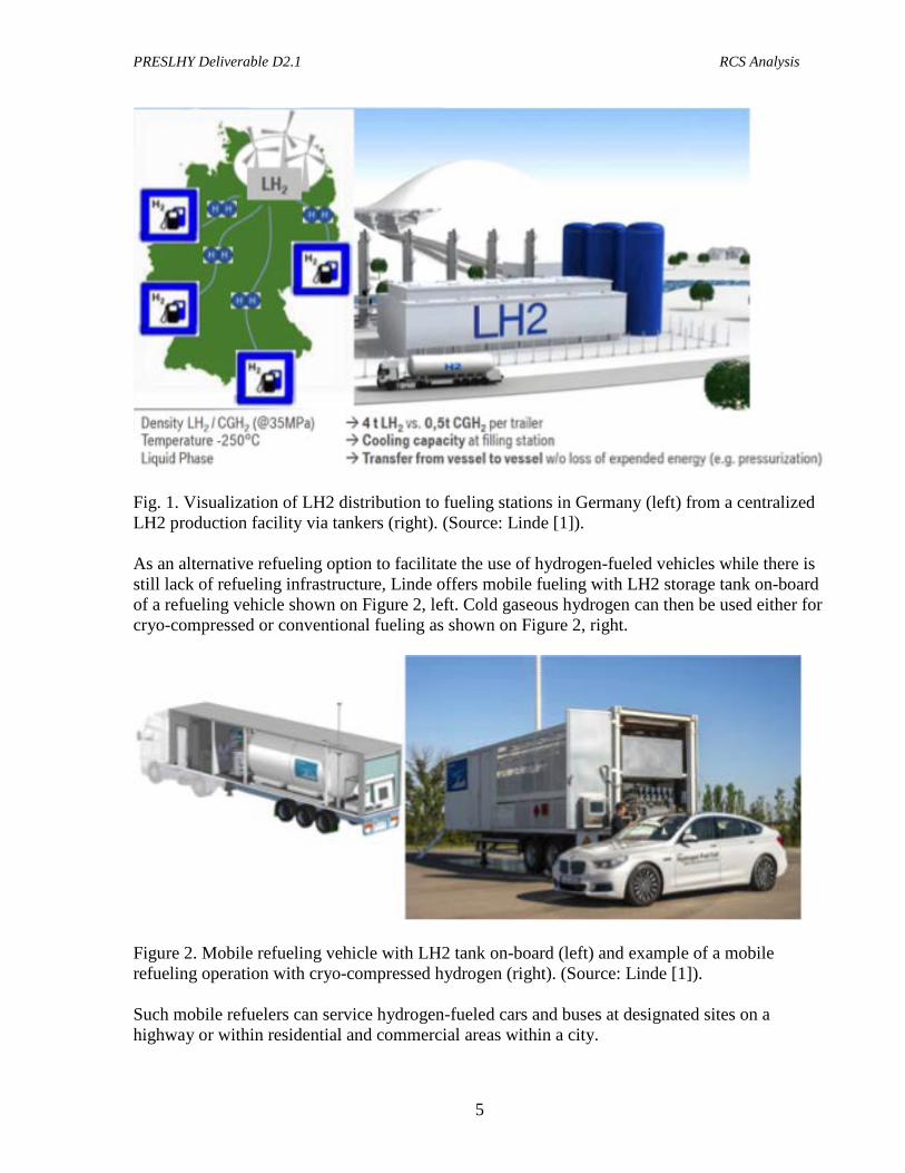
The above areas of concern are best illustrated by the Linde’s visual representation of LH2 and cryo-compressed (cold) hydrogen distribution for hydrogen fueling stations in Germany shown on the left image of Figure 1. At the same time, the right image on Figure 1 shows a large scale LH2 central production facility with a LH2 distribution tanker that has a much higher capacity than even cold cryo-compressed trailer (let alone a regular tube trailer).
PRESLHY Deliverable D2.1 RCS Analysis
5
Fig. 1. Visualization of LH2 distribution to fueling stations in Germany (left) from a centralized LH2 production facility via tankers (right). (Source: Linde [1]). As an alternative refueling option to facilitate the use of hydrogen-fueled vehicles while there is still lack of refueling infrastructure, Linde offers mobile fueling with LH2 storage tank on-board of a refueling vehicle shown on Figure 2, left. Cold gaseous hydrogen can then be used either for cryo-compressed or conventional fueling as shown on Figure 2, right.
Figure 2. Mobile refueling vehicle with LH2 tank on-board (left) and example of a mobile refueling operation with cryo-compressed hydrogen (right). (Source: Linde [1]). Such mobile refuelers can service hydrogen-fueled cars and buses at designated sites on a highway or within residential and commercial areas within a city.

PRESLHY Deliverable D2.1 RCS Analysis
6
Finally, Linde, in collaboration with Total and BMW, installed the first permanent hydrogen fueling station with LH2 storage tank and auxiliary equipment in an underground vault underneath gaseous hydrogen dispensers. Figure 3 shows the conceptual design (left) and its actual implementation at the Total petrol station in Munich (right).
Figure 3. Conceptual design (left) [1] and actual hydrogen dispenser (right, picture by A.V. Tchouvelev) of Linde LH2 station with a cryo pump and storage in the underground vault installed at the public Total petrol station in Munich. The above examples clearly indicate that liquid hydrogen delivery and use in urban environment became a reality.
2.2 PRESLHY RCS Goal To address the above concerns, PRESLHY application put forward the following RCS related goal: “With the new knowledge generated by this research work, science based and validated tools, which are required for hydrogen safety engineering, and risk-informed, performance based, LH2 specific, international standards will be developed.”
2.3 PRESLHY RCS Objectives The above goal has been addressed by the following RCS-related project objectives:
• Provide a report on the initial state-of-the-art, specific knowledge, specific international standards, safety strategies in existing installations and knowledge gaps with priorities related to the envisaged use of LH2
PRESLHY Deliverable D2.1 RCS Analysis
7
• Derive together with the standards developing organisations a list of priorities, which shall highlight those phenomena associated with highest risk scenarios, least knowledge and lack of reference guidelines and standards
• Provide a specially tailored summary report to support the international Standards Developing Organisations SDOs, in particular ISO/IEC and CEN/CENELEC, in either updating existing standards or developing new international performance based and risk informed standards.
2.3.1 RCS Task Objective To address the above objectives the RCS task was proposed. This task is dedicated to the survey on the existing Regulations, Code and Standards (RCS) as well as the industry best practices from European Industrial Gas Association (EIGA) and Compressed Gas Association (CGA). The existing RCS developed for small scale LNG applications (trucks, boats) will be also examined considering the analogy in the applications. Based on this survey, recommendations and prioritization on the subjects covered by RCS will be given. This task will be in collaboration with ISO TC197 members from Air Liquide and HySafe.
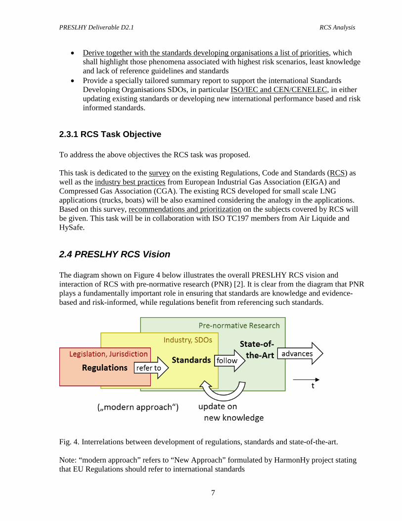
2.4 PRESLHY RCS Vision The diagram shown on Figure 4 below illustrates the overall PRESLHY RCS vision and interaction of RCS with pre-normative research (PNR) [2]. It is clear from the diagram that PNR plays a fundamentally important role in ensuring that standards are knowledge and evidence-based and risk-informed, while regulations benefit from referencing such standards.
Fig. 4. Interrelations between development of regulations, standards and state-of-the-art. Note: “modern approach” refers to “New Approach” formulated by HarmonHy project stating that EU Regulations should refer to international standards
PRESLHY Deliverable D2.1 RCS Analysis
8
3.0 Relevant Examples from LH2 Built Environment Perspective In the RCS framework of a PNR project such as PRESLHY, it is important analyze the relevant built environment, hazards and potential failure scenarios and phenomena that are most relevant or critical for LH2 facilities and equipment deployment.
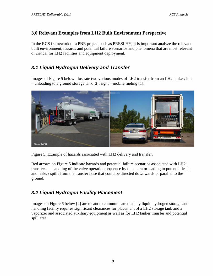
3.1 Liquid Hydrogen Delivery and Transfer Images of Figure 5 below illustrate two various modes of LH2 transfer from an LH2 tanker: left – unloading to a ground storage tank [3]; right – mobile fueling [1].
Figure 5. Example of hazards associated with LH2 delivery and transfer. Red arrows on Figure 5 indicate hazards and potential failure scenarios associated with LH2 transfer: mishandling of the valve operation sequence by the operator leading to potential leaks and leaks / spills from the transfer hose that could be directed downwards or parallel to the ground.
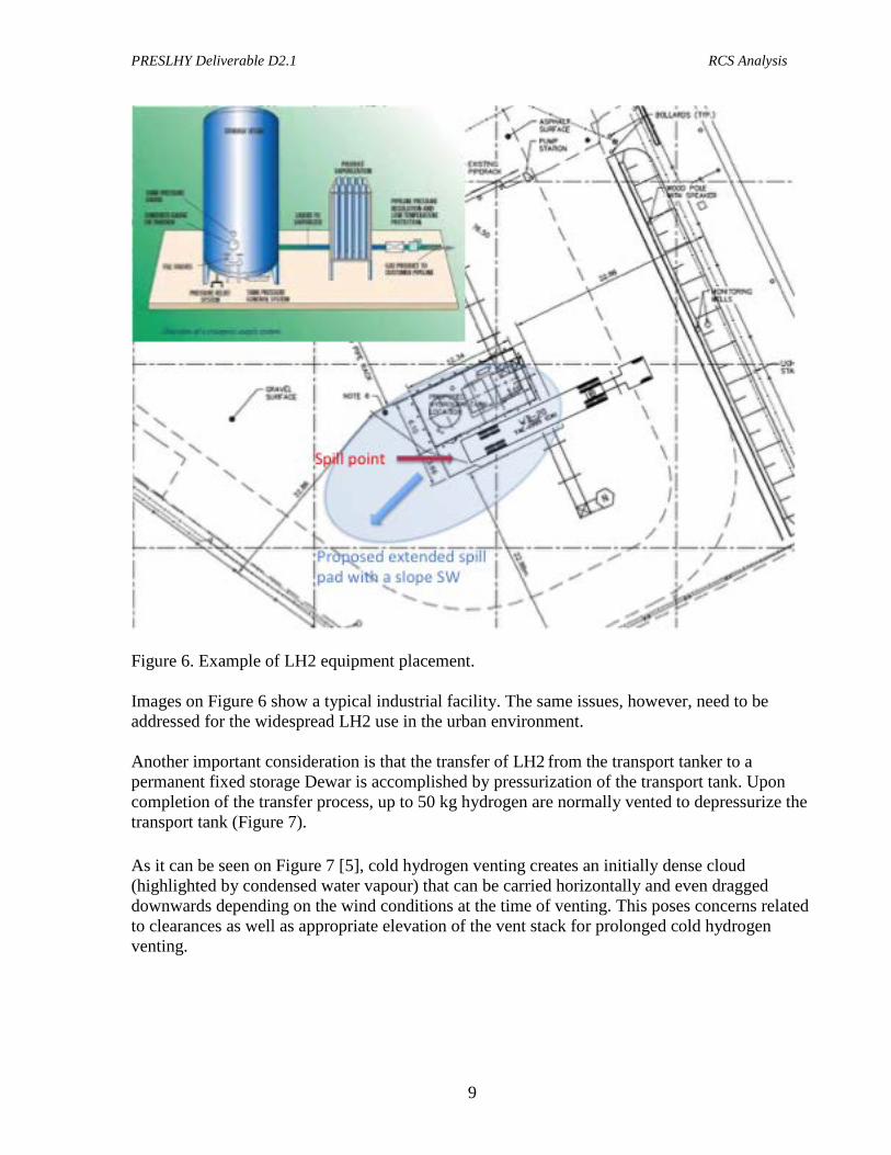
3.2 Liquid Hydrogen Facility Placement Images on Figure 6 below [4] are meant to communicate that any liquid hydrogen storage and handling facility requires significant clearances for placement of a LH2 storage tank and a vaporizer and associated auxiliary equipment as well as for LH2 tanker transfer and potential spill area.
PRESLHY Deliverable D2.1 RCS Analysis
9
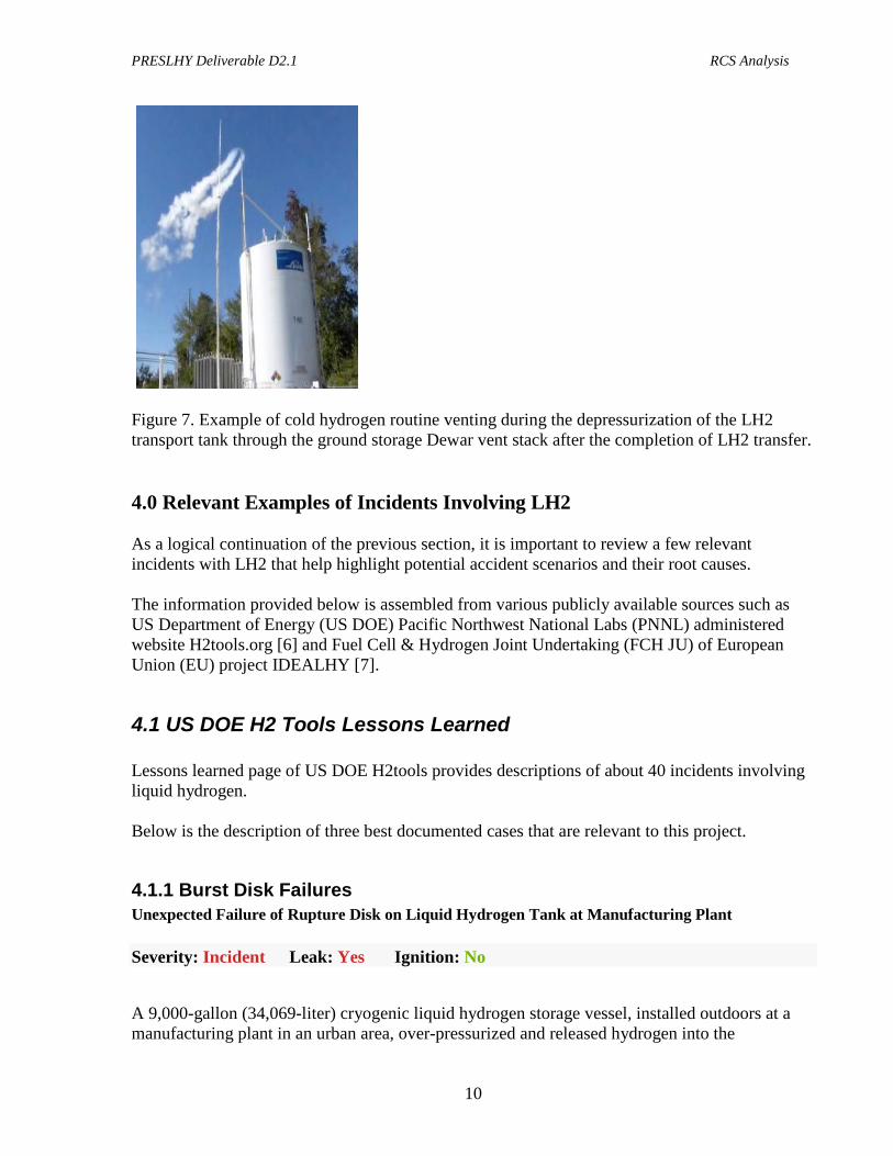
Figure 6. Example of LH2 equipment placement. Images on Figure 6 show a typical industrial facility. The same issues, however, need to be addressed for the widespread LH2 use in the urban environment. Another important consideration is that the transfer of LH2 from the transport tanker to a permanent fixed storage Dewar is accomplished by pressurization of the transport tank. Upon completion of the transfer process, up to 50 kg hydrogen are normally vented to depressurize the transport tank (Figure 7). As it can be seen on Figure 7 [5], cold hydrogen venting creates an initially dense cloud (highlighted by condensed water vapour) that can be carried horizontally and even dragged downwards depending on the wind conditions at the time of venting. This poses concerns related to clearances as well as appropriate elevation of the vent stack for prolonged cold hydrogen venting.
PRESLHY Deliverable D2.1 RCS Analysis
10
Figure 7. Example of cold hydrogen routine venting during the depressurization of the LH2 transport tank through the ground storage Dewar vent stack after the completion of LH2 transfer. 4.0 Relevant Examples of Incidents Involving LH2 As a logical continuation of the previous section, it is important to review a few relevant incidents with LH2 that help highlight potential accident scenarios and their root causes. The information provided below is assembled from various publicly available sources such as US Department of Energy (US DOE) Pacific Northwest National Labs (PNNL) administered website H2tools.org [6] and Fuel Cell & Hydrogen Joint Undertaking (FCH JU) of European Union (EU) project IDEALHY [7].
4.1 US DOE H2 Tools Lessons Learned Lessons learned page of US DOE H2tools provides descriptions of about 40 incidents involving liquid hydrogen. Below is the description of three best documented cases that are relevant to this project.
4.1.1 Burst Disk Failures Unexpected Failure of Rupture Disk on Liquid Hydrogen Tank at Manufacturing Plant Severity: Incident Leak: Yes Ignition: No
A 9,000-gallon (34,069-liter) cryogenic liquid hydrogen storage vessel, installed outdoors at a manufacturing plant in an urban area, over-pressurized and released hydrogen into the
PRESLHY Deliverable D2.1 RCS Analysis
11
atmosphere through a safety relief device (burst disk). When the burst disk released pressure, a loud bang was heard by neighbors and reported to the local police. The police investigated and heard the sound of gaseous hydrogen escaping from the vessel's vent stack, which rose approximately 15-20 feet (4.6-6.1 meters) in the air.
Police called the local fire department. Firefighters entered the facility and told employees inside that there was an explosion on the property and they needed to evacuate. As a precautionary measure, some nearby city buildings were also evacuated and the street was blocked off in front of the facility.
A facility representative went to the storage vessel to investigate. This individual saw that hydrogen was escaping from the vent stack, but there was no fire. The individual called the industrial gas company that services the installation to report the incident, and a field service technician was dispatched to the scene.
The technician arrived to find the tank pressure at zero and the burst disk blown. He switched the three-way diverter valve to the other safety relief device and replaced the burst disk when the line defrosted. After rebuilding the pressure, the field service technician leak-checked the lines and did not see any indication of fire at the stack ends.
Because the cryogenic liquid hydrogen storage vessel had experienced a long period of non-use, heating by the ambient air temperature (60°F/16°C) caused the vessel's internal temperature to rise even though it was vacuum-jacketed. The normal storage pressure for this vessel was 150 psi (10.3 bar). There were no injuries or damage from this incident, and inspectors from the manufacturing company and industrial gas company stated that the hydrogen safety venting equipment functioned properly. Normal operations resumed after it was determined that there were no unsafe conditions.
Approximately seven months later, the burst disk that had been replaced in the incident described above ruptured for the same reasons --- back pressure against the burst disk caused premature failure. No outside emergency response was involved with this second hydrogen venting incident, as once again the pressure relief system worked as designed. Following this incident, some modifications were made to the hydrogen piping to eliminate all back pressure on the burst disk. (Dated 2008, posted in Jan 2010).
No injury or property damage were reported.
Liquid Hydrogen Tank Boiling Liquid Expanding Vapor Explosion (BLEVE) due to Water-Plugged Vent Stack For unspecified reasons, a burst disk on a large liquid hydrogen tank blew and exhausted cold gaseous hydrogen through the vent stack. To stabilize the tank, the remaining hydrogen was removed from the tank except for a small volume in the heel of the tank that could not be removed manually. The tank vacuum was lost. Firefighters responding to the hydrogen release sprayed water on the tank and vent stack. Since the vent stack was open, some water entered and froze, plugging the stack and sealing off the only hydrogen pressure-relief exit path. In time, the tank warmed, became over-pressurized, and ruptured. In this case, the burst disk may have functioned properly as designed, but the vent stack design and the emergency response actions
PRESLHY Deliverable D2.1 RCS Analysis
12
did not allow the vent stack to function. The lessons learned are 1) to post signage indicating that no water is to be sprayed on the vent stack, and 2) to install a backup pressure-relief vent stack in case the main vent stack fails. Despite of the BLEVE event, and thanks to the very low residual inventory of LH2 in the tank, no injuries or property damage were reported.
4.1.2 Incident During LH2 Transfer The best-recorded incident related to liquid hydrogen transfer happened in 2004. On Friday evening, August 6, 2004, a plume of hydrogen gas escaped from the offloading valve of a Praxair liquid hydrogen delivery truck at a Ballard facility in Burnaby, BC. The plume ignited, resulting in a flash and concussion loud enough to be heard inside the nearby building and to set off the building’s seismic event detectors. A small amount of hydrogen gas continued to escape from the trailer tank and burn until a Praxair specialist arrived to manually shut off a critical valve almost eight hours later. In the meantime, emergency response crews called to the scene sprayed water across the hydrogen tank as a precautionary cooling measure.
The local news media reported the story as a collision: “Hydrogen tanker crashes at Ballard Power Systems spewing gas,” (Canadian Press, Saturday, August 07, 2004). Various other reports described the event using terms such as “explosion,” “noxious fumes,” and “incredibly flammable.”
The facts of the incident turned out to be much less sensational than originally reported. Between investigation of the physical evidence, interviewing the driver, and reviewing security videos from the facility, the actual cause of this incident appears to have been primarily driver error. A number of steps required as part of the standard safety procedure were either incorrectly applied or omitted altogether. In any case, there was no crash or any compromise in the integrity of the fuel tank aboard the truck trailer. Attentiveness to proper procedure would have prevented this incident.
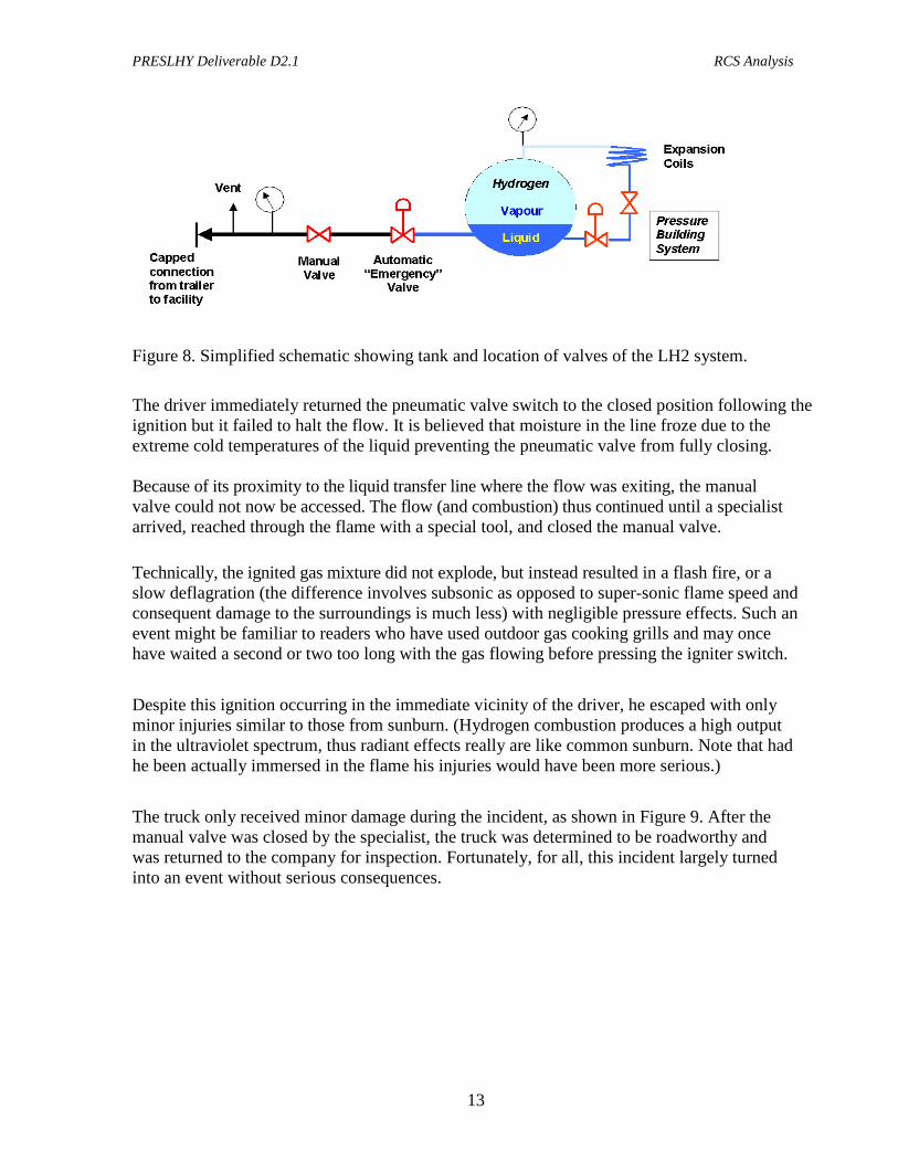
The problem appears to have started when the driver of the truck was preparing to complete the second of two deliveries at the facility. (A rough schematic of the tank system is shown in Figure 8.) The manual valve shown in the figure was apparently left in an open position following the first unloading. The driver next failed to perform the required procedure of seven purges intended to eliminate contaminants and water from the piping before connecting the hose for the second unloading. He then opened the pneumatic (“automatic” in Figure 8) valve before connecting the hose, which, due to the open manual valve, resulted in a direct release of liquid hydrogen into the ambient air. This liquid immediately vaporized into a hydrogen cloud and quickly ignited. The cause of ignition is still uncertain, but one theory is that a static electricity buildup caused by the rush of vaporizing gas self-ignited the mixture.
PRESLHY Deliverable D2.1 RCS Analysis
13
Figure 8. Simplified schematic showing tank and location of valves of the LH2 system.
The driver immediately returned the pneumatic valve switch to the closed position following the ignition but it failed to halt the flow. It is believed that moisture in the line froze due to the extreme cold temperatures of the liquid preventing the pneumatic valve from fully closing. Because of its proximity to the liquid transfer line where the flow was exiting, the manual valve could not now be accessed. The flow (and combustion) thus continued until a specialist arrived, reached through the flame with a special tool, and closed the manual valve. Technically, the ignited gas mixture did not explode, but instead resulted in a flash fire, or a slow deflagration (the difference involves subsonic as opposed to super-sonic flame speed and consequent damage to the surroundings is much less) with negligible pressure effects. Such an event might be familiar to readers who have used outdoor gas cooking grills and may once have waited a second or two too long with the gas flowing before pressing the igniter switch. Despite this ignition occurring in the immediate vicinity of the driver, he escaped with only minor injuries similar to those from sunburn. (Hydrogen combustion produces a high output in the ultraviolet spectrum, thus radiant effects really are like common sunburn. Note that had he been actually immersed in the flame his injuries would have been more serious.) The truck only received minor damage during the incident, as shown in Figure 9. After the manual valve was closed by the specialist, the truck was determined to be roadworthy and was returned to the company for inspection. Fortunately, for all, this incident largely turned into an event without serious consequences.
PRESLHY Deliverable D2.1 RCS Analysis
14
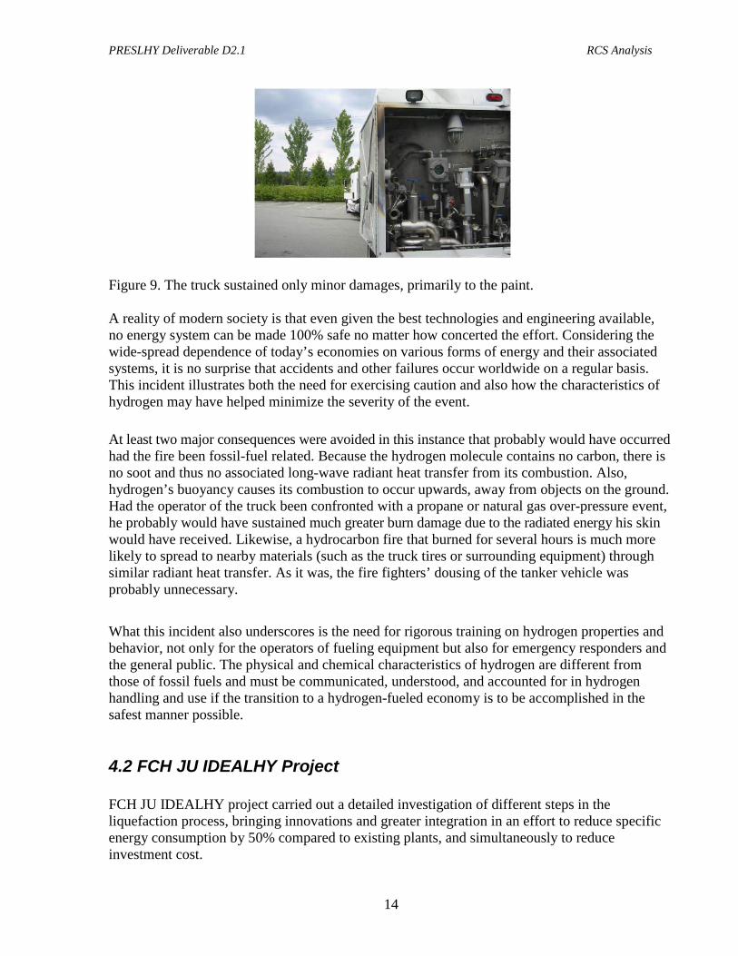
Figure 9. The truck sustained only minor damages, primarily to the paint. A reality of modern society is that even given the best technologies and engineering available, no energy system can be made 100% safe no matter how concerted the effort. Considering the wide-spread dependence of today’s economies on various forms of energy and their associated systems, it is no surprise that accidents and other failures occur worldwide on a regular basis. This incident illustrates both the need for exercising caution and also how the characteristics of hydrogen may have helped minimize the severity of the event. At least two major consequences were avoided in this instance that probably would have occurred had the fire been fossil-fuel related. Because the hydrogen molecule contains no carbon, there is no soot and thus no associated long-wave radiant heat transfer from its combustion. Also, hydrogen’s buoyancy causes its combustion to occur upwards, away from objects on the ground. Had the operator of the truck been confronted with a propane or natural gas over-pressure event, he probably would have sustained much greater burn damage due to the radiated energy his skin would have received. Likewise, a hydrocarbon fire that burned for several hours is much more likely to spread to nearby materials (such as the truck tires or surrounding equipment) through similar radiant heat transfer. As it was, the fire fighters’ dousing of the tanker vehicle was probably unnecessary. What this incident also underscores is the need for rigorous training on hydrogen properties and behavior, not only for the operators of fueling equipment but also for emergency responders and the general public. The physical and chemical characteristics of hydrogen are different from those of fossil fuels and must be communicated, understood, and accounted for in hydrogen handling and use if the transition to a hydrogen-fueled economy is to be accomplished in the safest manner possible.
4.2 FCH JU IDEALHY Project FCH JU IDEALHY project carried out a detailed investigation of different steps in the liquefaction process, bringing innovations and greater integration in an effort to reduce specific energy consumption by 50% compared to existing plants, and simultaneously to reduce investment cost.

PRESLHY Deliverable D2.1 RCS Analysis
15
IDEALHY also carried out a well-to-end-user analysis to illustrate the role of liquid hydrogen in the energy chain, with an assessment of safety and risk mitigation in the overall chain for liquid hydrogen. This assessment also included review and analyses of recorded incidents with transportation and handling of liquid hydrogen. Speaking specifically on BLEVE, IDEALHY concludes that “Experimental data on BLEVEs is available for butane, propane and fireballs involving natural gas, but no information has been identified for LH2. In many cases, the dimensions of the fireball are correlated with the mass of fuel involved in the fireball.”
4.2.1 Road Transportation Incidents Of the 18 incidents identified, 5 (28%) occurred in transit and 13 (72%) during loading/offloading. The causes of the incidents were classified as follows: Design/Construction failure/inadequate Hazard Assessment 0 (0%); Equipment failure 6 (33%); Incorrect operation / procedural deficiency/poor maintenance 8 (44%); Impact or Road Traffic Accidents RTA 3 (17%); Contamination 0 (0%); Natural causes/Terrorism 1 (5%); Escalation 0 (0%). All the incidents attributed to Incorrect operation/Procedural deficiency arose during offloading operations. For example, due to over-pressurizing the head space, or operating valves incorrectly or too quickly. Deviating from procedures relating to transfer hoses was also noted and using an impromptu procedure accounted for one incident. The consequences of these incidents were varied leading to gas venting, sometimes liquid release, fire, gas entering a building, and explosion. Equipment failure included unexpected burst disc failure, loss of vacuum or a loose flange connection. Of the 5 cases during transit, 2 related to Road Traffic Accidents (RTA) and the other 3 concerned venting due to burst disc failure and/or loss of vacuum. In one of the RTAs, the tanker overturned and landed in a ditch. Subsequently, the safety discs functioned and the liquid load was dumped. In the event of blockage of the relief, this incident could have resulted in more serious consequences. Overall, the consequences which arose were: No release 2 (11%); Accumulation/Dispersion 12 (67%); Fire 4 (22%); Explosion 1 (5%); BLEVE 0 (0%). (Note: multiple consequences can arise). Injury to personnel occurred in 3 (17%) cases, 2 of which were cold burns. This rate of injury is greater than that noted for incidents concerning storage and liquefaction (see below) and probably reflects the required proximity of personnel during tanker operations. Property/equipment damage occurred in 7 (39%) of cases.
4.2.2 Liquefaction and Storage Incidents Of the 39 incidents identified, the locations of the incidents were: Liquefier/Purifier 2 (5%); Vent system and pipework 11 (28%); Storage vessels including fittings, valves and reliefs 14 (36%); Valves/Components/Fittings 6 (15%); Pumps/Compressors/Vaporizers 6 (15%); Transfer lines/ pipelines 5 (13%).
PRESLHY Deliverable D2.1 RCS Analysis
16
Incidents concerning storage vessels had a tendency to be either minor in nature, that is, a small leak from a fitting or valve packing or a major incident. It was also noted that out of 6 major incidents involving storage vessels, 3 occurred during decommissioning/commissioning (warm-up/cool-down). Further two less serious incidents also occurred when the vessel was not in service. There were several incidents relating to venting systems where unexpected ignition had occurred resulting in fire or explosion in vent system pipework or in the vicinity of the vent stack outlet. The causes of the incidents were classified as: Design/Construction failure/Inadequate Hazard Assessment 12 (31%); Equipment failure 8 (21%); Incorrect operation/procedural deficiency/poor maintenance 18 (46%); Impact or RTA 0 (0%); Contamination 1 (3%); Natural causes/Terrorism 5 (13%); Escalation 2 (5%). (Note: multiple causes in some cases). The incidents attributed to poor design included 4 where the wrong material had been used. Two cases related to storage systems, which were over-sized and, after a prolonged period of storage, this led to failure of a burst disc and a leak from a gland nut. Two other cases were interesting in that it was inadequate hazard assessment (perhaps due to insufficient knowledge at the time), which led to an unforeseen explosion in the vicinity of a vent stack. It had been assumed that the hydrogen would disperse quickly, but due to prolonged venting of cold gas in calm conditions an accumulation formed around the vent stack, which then ignited. Incorrect operation, procedural deficiency or poor maintenance was the most common cause, as it was for the transportation incidents. Of these 18 incidents, 7 were attributed to inadequate purging, leading to the formation of a flammable mixture. In terms of equipment failure, this typically related to leaking seals, valve packings or O rings. Two incidents were attributed to an escalation event. In both cases, an improper method of fire fighting was used:
• In one case, firefighters were attending a fire on a vessel relief vent. Although the vessel had been part drained, some LH2 remained in the tank. The firefighters directed water at the fire on the relief and water entered the vent and froze, blocking it. The residual LH2 warmed up, vaporised and due to the blocked relief, a BLEVE occurred.
• In the second case, again, a fire was present on a vessel relief. Firefighters attempted to
protect an adjacent vessel by spraying it with liquid nitrogen, but the cold temperatures caused cracking of the outer skin of the vessel and loss of the vacuum. This caused a rapid increase in temperature and pressure. Subsequent failure of the rupture disc on this second vessel resulted in an additional fire, as the contents of this vessel boiled off. Although it did not occur in this case, the potential for a BLEVE is obvious.
In 4 incidents cold weather and/or still conditions contributed to the cause of an incident and in one case lightning was believed to have ignited a vent stack.
PRESLHY Deliverable D2.1 RCS Analysis
17
Overall, the consequences, which arose from the incidents, were: No release 5 (13%); Accumulation or Dispersion 14 (36%); Fire 9 (23%); Explosion 13 (33%); BLEVE 1 (3%). Injury occurred in 3 (8%) of incidents and non-trivial damage in 23 (59%) of cases. Note: apparently there was one case of attempted terrorism, but since there was no specific description, it did not result in significant damage, if any.
4.3 Discussion Based on the reported evidence, it is clear that despite occasional rupture disk failures and operator errors leading to occasional gas venting and fires, the overall safety record of LH2 delivery, transfer and storage is very impressive. There were no recorded fatalities and only relatively minor injuries reported. Property damage was either none or not significant. Ironically, most hazardous situations were created by the erroneous / inappropriate actions of the first responders / fire fighters due to lack of knowledge of and training on LH2. Events like BLEVE and fireballs, typical for cryogenic hydrocarbons such as primarily LPG (propane and butane) and to the lesser extent LNG, appear to be not very typical for liquid hydrogen and mostly come from the academic / research assessments. Many assessments, for example, consider that all content of a ruptured tank will ignite simultaneously thus producing an enormous size fireball. In reality, such phenomena are not possible: even after a tank rupture, most of the hydrogen is still in liquid form, the produced gas is very cold and concentrated and, thus, cannot all ignite at once. In this case, a relatively small flash fire is a much more realistic scenario. 5.0 LH2 Research Relevant to RCS In the opinion of the author of this report, the most relevant experiments were performed by Health and Safety Lab (HSL) in UK, Buxton.
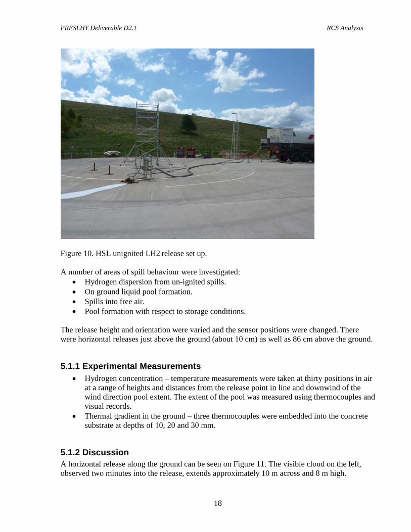
5.1 Unignited Releases During 2009-2011 HSL performed experiments on large-scale un-ignited releases of LH2 with the aim of determining the range of hazards from a realistic release of LH2 [8]. The work involved releasing LH2 (from a 2.5 ton capacity LH2 tanker) at fixed conditions of 1 barg in the tanker through 20 m of 1” hose, which gave a rate of 60 L per minute for differing durations. The release height and orientation were varied and the sensor positions were changed. The release system is shown on Figure 10 below.
PRESLHY Deliverable D2.1 RCS Analysis
18
Figure 10. HSL unignited LH2 release set up. A number of areas of spill behaviour were investigated:
• Hydrogen dispersion from un-ignited spills. • On ground liquid pool formation. • Spills into free air. • Pool formation with respect to storage conditions.
The release height and orientation were varied and the sensor positions were changed. There were horizontal releases just above the ground (about 10 cm) as well as 86 cm above the ground.
5.1.1 Experimental Measurements • Hydrogen concentration – temperature measurements were taken at thirty positions in air
at a range of heights and distances from the release point in line and downwind of the wind direction pool extent. The extent of the pool was measured using thermocouples and visual records.
• Thermal gradient in the ground – three thermocouples were embedded into the concrete substrate at depths of 10, 20 and 30 mm.
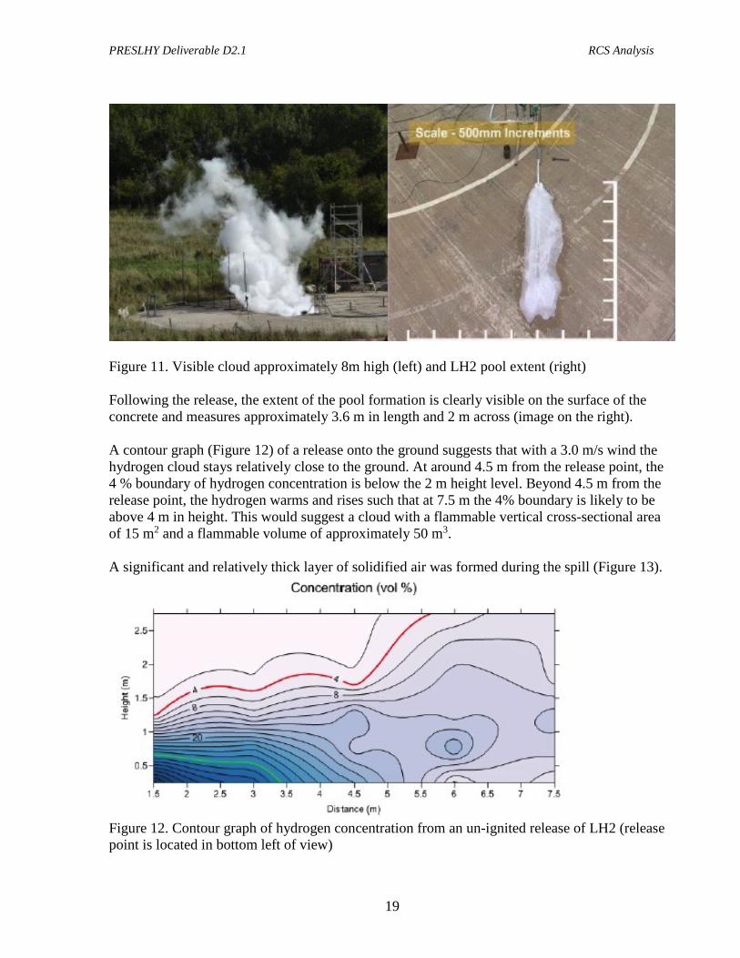
5.1.2 Discussion A horizontal release along the ground can be seen on Figure 11. The visible cloud on the left, observed two minutes into the release, extends approximately 10 m across and 8 m high.
PRESLHY Deliverable D2.1 RCS Analysis
19
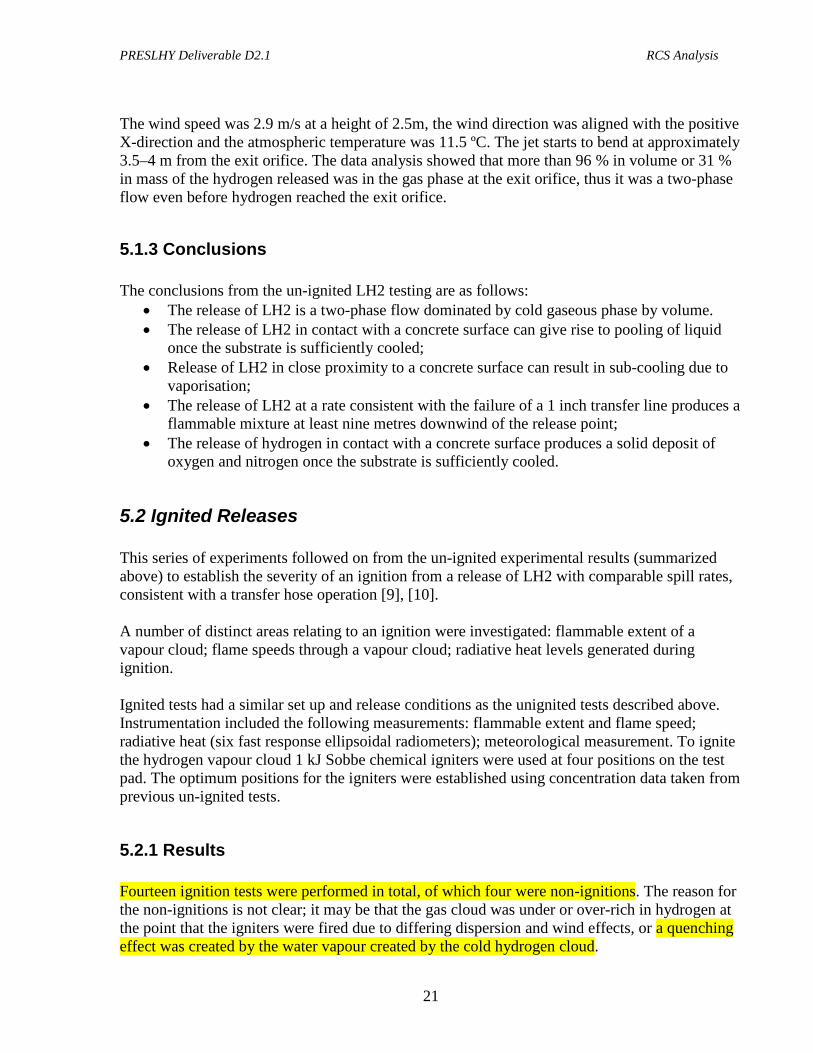
Figure 11. Visible cloud approximately 8m high (left) and LH2 pool extent (right) Following the release, the extent of the pool formation is clearly visible on the surface of the concrete and measures approximately 3.6 m in length and 2 m across (image on the right). A contour graph (Figure 12) of a release onto the ground suggests that with a 3.0 m/s wind the hydrogen cloud stays relatively close to the ground. At around 4.5 m from the release point, the 4 % boundary of hydrogen concentration is below the 2 m height level. Beyond 4.5 m from the release point, the hydrogen warms and rises such that at 7.5 m the 4% boundary is likely to be above 4 m in height. This would suggest a cloud with a flammable vertical cross-sectional area of 15 m2 and a flammable volume of approximately 50 m3. A significant and relatively thick layer of solidified air was formed during the spill (Figure 13).
Figure 12. Contour graph of hydrogen concentration from an un-ignited release of LH2 (release point is located in bottom left of view)

PRESLHY Deliverable D2.1 RCS Analysis
20
Figure 13. Solidified air formed during the LH2 spill experiments. A horizontal release 86 cm above the ground can be seen on Figure 14.
Figure 14. HSL LH2 horizontal release test 86 cm above ground.
PRESLHY Deliverable D2.1 RCS Analysis
21
The wind speed was 2.9 m/s at a height of 2.5m, the wind direction was aligned with the positive X-direction and the atmospheric temperature was 11.5 ºC. The jet starts to bend at approximately 3.5–4 m from the exit orifice. The data analysis showed that more than 96 % in volume or 31 % in mass of the hydrogen released was in the gas phase at the exit orifice, thus it was a two-phase flow even before hydrogen reached the exit orifice.
5.1.3 Conclusions The conclusions from the un-ignited LH2 testing are as follows:
• The release of LH2 is a two-phase flow dominated by cold gaseous phase by volume. • The release of LH2 in contact with a concrete surface can give rise to pooling of liquid
once the substrate is sufficiently cooled; • Release of LH2 in close proximity to a concrete surface can result in sub-cooling due to
vaporisation; • The release of LH2 at a rate consistent with the failure of a 1 inch transfer line produces a
flammable mixture at least nine metres downwind of the release point; • The release of hydrogen in contact with a concrete surface produces a solid deposit of
oxygen and nitrogen once the substrate is sufficiently cooled.
5.2 Ignited Releases This series of experiments followed on from the un-ignited experimental results (summarized above) to establish the severity of an ignition from a release of LH2 with comparable spill rates, consistent with a transfer hose operation [9], [10]. A number of distinct areas relating to an ignition were investigated: flammable extent of a vapour cloud; flame speeds through a vapour cloud; radiative heat levels generated during ignition. Ignited tests had a similar set up and release conditions as the unignited tests described above. Instrumentation included the following measurements: flammable extent and flame speed; radiative heat (six fast response ellipsoidal radiometers); meteorological measurement. To ignite the hydrogen vapour cloud 1 kJ Sobbe chemical igniters were used at four positions on the test pad. The optimum positions for the igniters were established using concentration data taken from previous un-ignited tests.
5.2.1 Results Fourteen ignition tests were performed in total, of which four were non-ignitions. The reason for the non-ignitions is not clear; it may be that the gas cloud was under or over-rich in hydrogen at the point that the igniters were fired due to differing dispersion and wind effects, or a quenching effect was created by the water vapour created by the cold hydrogen cloud.
PRESLHY Deliverable D2.1 RCS Analysis
22
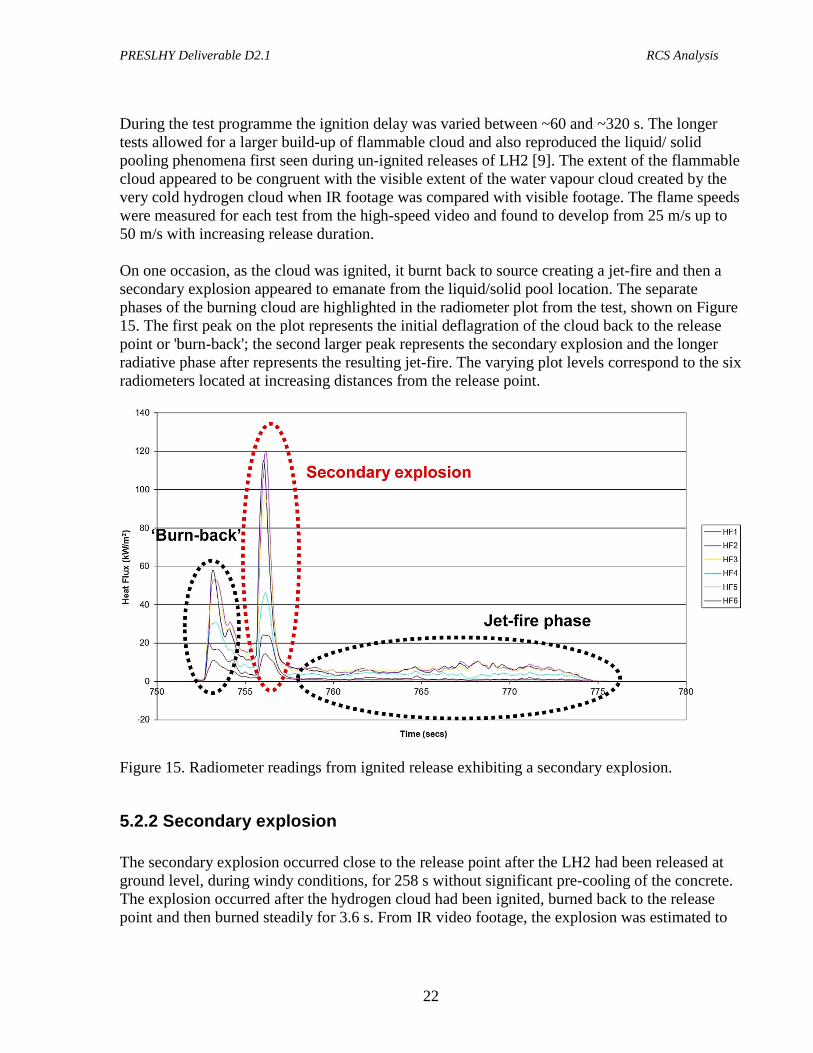
During the test programme the ignition delay was varied between ~60 and ~320 s. The longer tests allowed for a larger build-up of flammable cloud and also reproduced the liquid/ solid pooling phenomena first seen during un-ignited releases of LH2 [9]. The extent of the flammable cloud appeared to be congruent with the visible extent of the water vapour cloud created by the very cold hydrogen cloud when IR footage was compared with visible footage. The flame speeds were measured for each test from the high-speed video and found to develop from 25 m/s up to 50 m/s with increasing release duration. On one occasion, as the cloud was ignited, it burnt back to source creating a jet-fire and then a secondary explosion appeared to emanate from the liquid/solid pool location. The separate phases of the burning cloud are highlighted in the radiometer plot from the test, shown on Figure 15. The first peak on the plot represents the initial deflagration of the cloud back to the release point or 'burn-back'; the second larger peak represents the secondary explosion and the longer radiative phase after represents the resulting jet-fire. The varying plot levels correspond to the six radiometers located at increasing distances from the release point.
Figure 15. Radiometer readings from ignited release exhibiting a secondary explosion.
5.2.2 Secondary explosion The secondary explosion occurred close to the release point after the LH2 had been released at ground level, during windy conditions, for 258 s without significant pre-cooling of the concrete. The explosion occurred after the hydrogen cloud had been ignited, burned back to the release point and then burned steadily for 3.6 s. From IR video footage, the explosion was estimated to
PRESLHY Deliverable D2.1 RCS Analysis
23
be of a hemispherical profile and approximately 8 m in diameter, emanating 2.5 m from the release point, corresponding with the location of the solid/liquid pool seen prior to ignition. Several attempts were made to reproduce this phenomenon without success, although the conditions on subsequent occasions were far less windy, with the wind in the opposite direction. It is possible that oxygen enrichment of the condensed air may have occurred due to oxygen's higher boiling temperature (90.19 K) than nitrogen (77.36 K), an effect that may have been more likely during the windy conditions. It is postulated that the explosion was either a gas phase explosion resulting from a sudden release of oxygen from the solid due to a rapid phase change, or even a rapid reaction within the condensed slurry of solidified air and LH2 if the oxygen concentration were high enough [6]. Unfortunately, at the time of the explosion no pressure measurements were being made. Therefore, it was necessary to estimate the “size” of the explosion by other means.
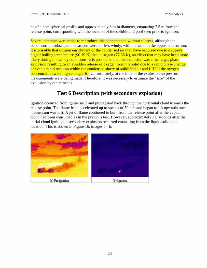
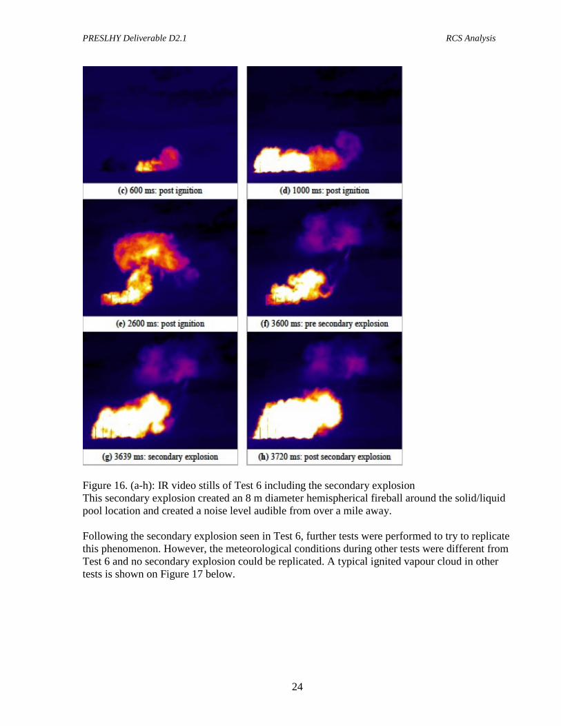
Test 6 Description (with secondary explosion) Ignition occurred from igniter no.3 and propagated back through the horizontal cloud towards the release point. The flame front accelerated up to speeds of 50 m/s and began to lift upwards once momentum was lost. A jet of flame continued to burn from the release point after the vapour cloud had been consumed as in the previous test. However, approximately 3.6 seconds after the initial cloud ignition, a secondary explosion occurred emanating from the liquid/solid pool location. This is shown in Figure 16, images f – h.
PRESLHY Deliverable D2.1 RCS Analysis
24
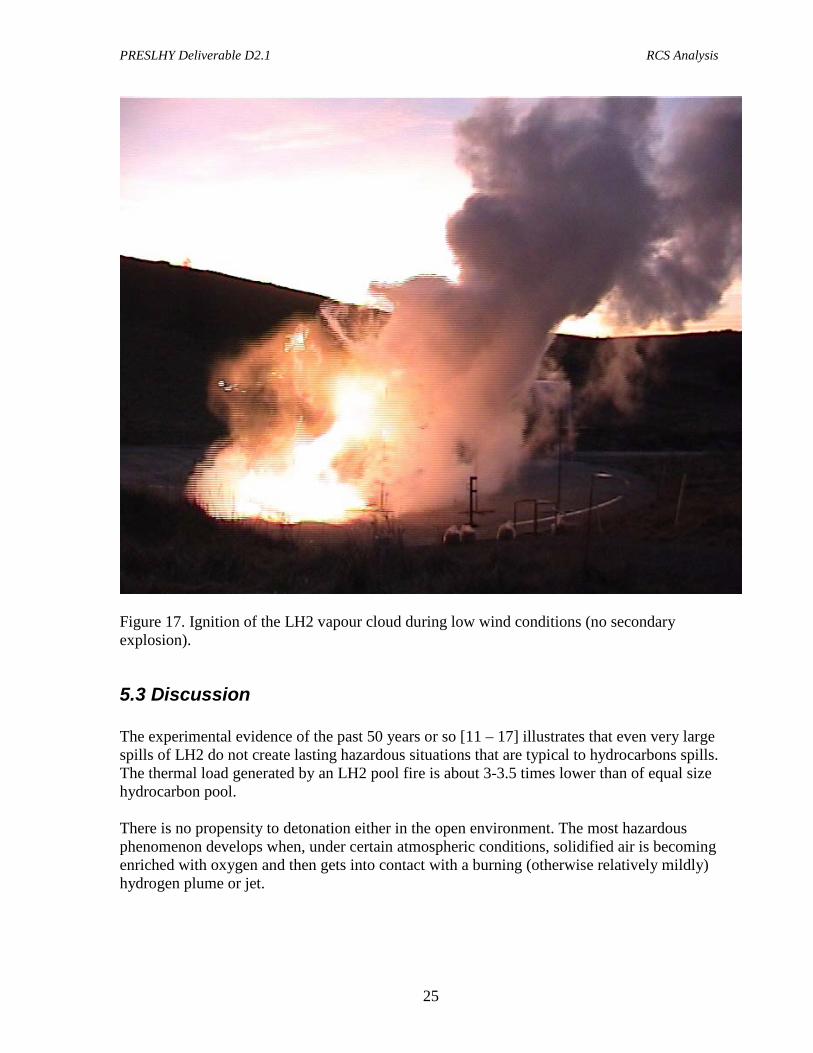
Figure 16. (a-h): IR video stills of Test 6 including the secondary explosion This secondary explosion created an 8 m diameter hemispherical fireball around the solid/liquid pool location and created a noise level audible from over a mile away. Following the secondary explosion seen in Test 6, further tests were performed to try to replicate this phenomenon. However, the meteorological conditions during other tests were different from Test 6 and no secondary explosion could be replicated. A typical ignited vapour cloud in other tests is shown on Figure 17 below.
PRESLHY Deliverable D2.1 RCS Analysis
25
Figure 17. Ignition of the LH2 vapour cloud during low wind conditions (no secondary explosion).
5.3 Discussion The experimental evidence of the past 50 years or so [11 – 17] illustrates that even very large spills of LH2 do not create lasting hazardous situations that are typical to hydrocarbons spills. The thermal load generated by an LH2 pool fire is about 3-3.5 times lower than of equal size hydrocarbon pool. There is no propensity to detonation either in the open environment. The most hazardous phenomenon develops when, under certain atmospheric conditions, solidified air is becoming enriched with oxygen and then gets into contact with a burning (otherwise relatively mildly) hydrogen plume or jet.
PRESLHY Deliverable D2.1 RCS Analysis
26
From this perspective, a secondary explosion induced by solid oxygen-enriched air (as was registered by HSL in their test 6) appears to be more hazardous event than a BLEVE (considering a LH2 spill and a BLEVE occur on an equal size tanker). A BLEVE that would result in a tank failure and instantaneous spill of all LH2 inventory, will of course freeze surrounding air. But, since the amount of LH2 will be dominant (vs a spill that develops gradually), this solid air will not have time to get enriched with oxygen and, since it is heavier than LH2, it will be covered by the evaporating liquid. We know from the NASA and AD Little experiments that whether the liquid is ignited or not, it does not affect LH2 pool evaporation or its regression rate. As was shown by Urano [17], the only real accelerant is the contact with solid air enriched with oxygen. But since under BLEVE condition it is covered by the liquid hydrogen, it is not involved in the combustion until most of the liquid has evaporated and risen to the atmosphere. Hence, solidified air would only affect a relatively small quantity of hydrogen and since it is not oxygen-enriched, an “explosion” (which would be a fast deflagration) is unlikely as was shown by HSL experiments. The unignited test by HSL performed at 86 cm above ground demonstrated that it does not result in solidification of air. It is possible that some sort of air “rain” or droplets might be present in the jet shown on Figure 14. However, due to moisture content in the air that condenses together with air in the cold hydrogen plume, the potential for oxygen enriched air is significantly reduced, if not completely eliminated. In this case, a secondary explosion observed on test 6 would not be possible. However, because the hydrogen plume is high enough above the ground and thus free from its friction, it may travel farther than the evaporating cloud from the LH2 pool. Hence, this scenario presents a new condition worth analyzing separately. Finally, the recent analysis of unignited experiments by HSL has shown that the gas-liquid slurry coming out of release orifice is a two-phase fluid even before it reaches the orifice. Calculations showed that the exit it consists of gas 96% by volume and 31% by mass. This indicates that analyzing (cold) hydrogen gas leaks is as relevant as analyzing the liquid ones. 6.0 Recommended RCS Priority Areas for PNR RCS areas for liquid hydrogen listed below have been selected based on the above evidence and considerations, extensive experience with the deployment of hydrogen infrastructure, long term involvement with the PNR on hydrogen safety as well as international and national codes and standards and regulations development. The topics below are recommended as priority areas for PNR on liquid hydrogen:
1. Safety / separation distances: a. Cold gas venting (delayed ignition, thermal) b. Pool fire (thermal) c. Solid air / oxygen effect (over pressure)
2. Hazardous areas: a. Should they be different than for gaseous hydrogen (GH2)?

PRESLHY Deliverable D2.1 RCS Analysis
27
3. Vent stacks design for cold gas venting: a. Orientation, pipe diameter, elevation
4. LH2 delivery and transfer: a. Spill control / prevention b. Spill mitigation (e.g. prevention of pooling)
7.0 RCS and Best Practices Most Relevant to Priority Areas For the purposes of this report and PRESLHY needs, we will review in detail only the most relevant documents and from the perspective of the above identified four priority areas.
7.1 NFPA Standards National Fire Protection Association or NFPA publishes two very relevant standards, NFPA 55 Compressed Gases and Cryogenic Fluids Code (latest published is 2013 edition) [18] and NFPA 2 Hydrogen Technologies Code (latest published is 2016 edition) [19]. With respect to liquid hydrogen both standards’ requirements are virtually identical and most of NFPA 2 LH2 related clauses come from NFPA 55. The nuances between the two relate to the coverage: NFPA 55 covers bulk storage, while NFPA 2 covers both bulk and non-bulk storage applications. Also, NFPA 2 covers hydrogen fueling facilities, while NFPA 55 does not.
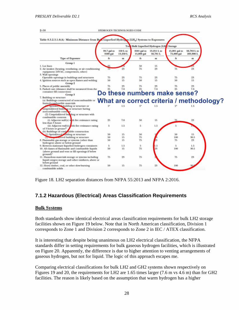
7.1.1 Separation Distances Both latest editions of NFPA 55 and NFPA 2 provide identical separation distances for liquid hydrogen shown on Figure 18 below. Very important questions arising from this table for both PNR and built environment placement of LH2 facilities are highlighted by red circles on table:
• The table covers LH2 storage capacities ranging from 150 L to 283906 L (or over 1890 times difference in capacity), while the maximum separation distances differ only by the factor of 3 and some separation distances remain the same and seem independent on the amount of LH2 storage.
• Maximum separation distances are 30.5 m (100 ft). Note: 100 ft was mentioned in A.D. Little (1960) videos as the worst case separation from the effects of premixed combustion / deflagration tests.
• Fire resistance rating of 3 hrs for unsprinklered buildings or structures is required to significantly reduce (from 5 to 15 times) the separation distances.
Do these numbers make sense for practical applications? What is the rationale behind them? For example, will an LH2 fire even last that long (3 hrs)? Etc.
PRESLHY Deliverable D2.1 RCS Analysis
28
Figure 18. LH2 separation distances from NFPA 55:2013 and NFPA 2:2016.
7.1.2 Hazardous (Electrical) Areas Classification Requirements Bulk Systems Both standards show identical electrical areas classification requirements for bulk LH2 storage facilities shown on Figure 19 below. Note that in North American classification, Division 1 corresponds to Zone 1 and Division 2 corresponds to Zone 2 in IEC / ATEX classification. It is interesting that despite being unanimous on LH2 electrical classification, the NFPA standards differ in setting requirements for bulk gaseous hydrogen facilities, which is illustrated on Figure 20. Apparently, the difference is due to higher attention to venting arrangements of gaseous hydrogen, but not for liquid. The logic of this approach escapes me. Comparing electrical classifications for bulk LH2 and GH2 systems shown respectively on Figures 19 and 20, the requirements for LH2 are 1.65 times larger (7.6 m vs 4.6 m) than for GH2 facilities. The reason is likely based on the assumption that warm hydrogen has a higher

PRESLHY Deliverable D2.1 RCS Analysis
29
buoyancy than cold hydrogen and thus less likely to spread in the horizontal direction than cold hydrogen upon exiting from the vent stack.
Figure 19. Bulk LH2 systems electrical area classification from NFPA 55:2013 and NFPA 2:2016.
PRESLHY Deliverable D2.1 RCS Analysis
30
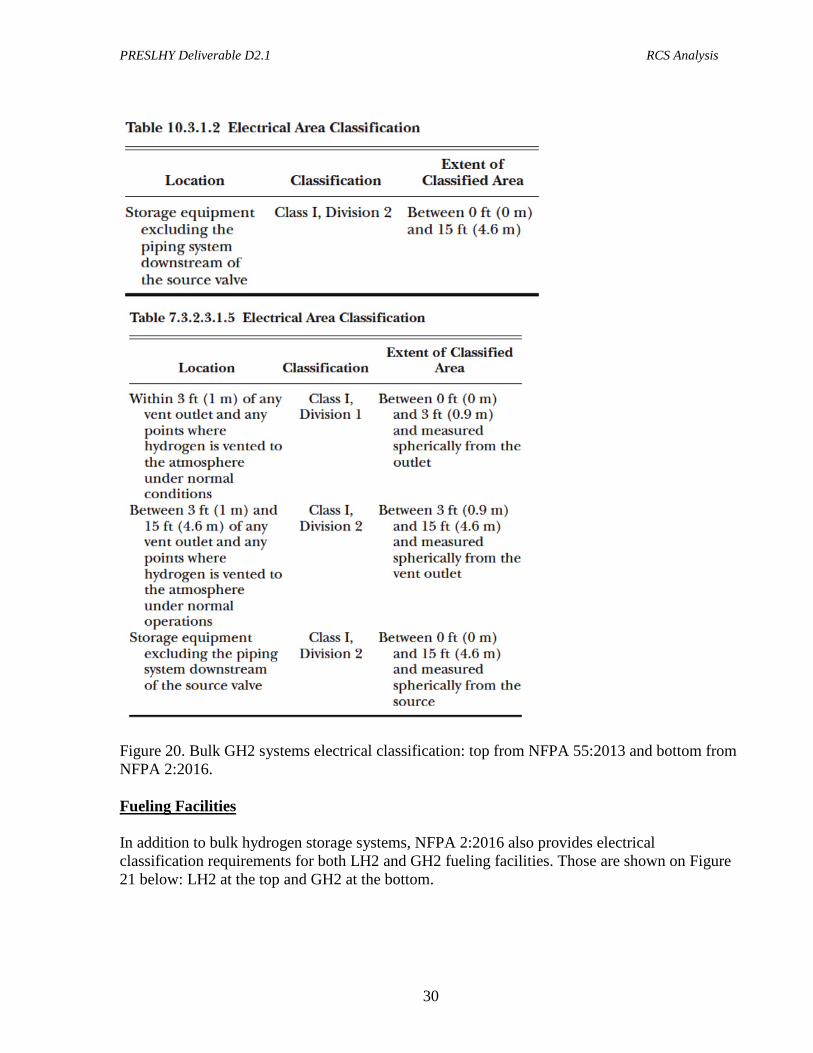
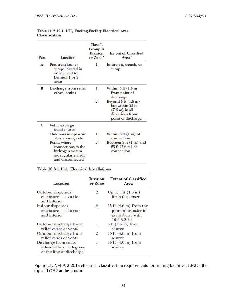
Figure 20. Bulk GH2 systems electrical classification: top from NFPA 55:2013 and bottom from NFPA 2:2016. Fueling Facilities In addition to bulk hydrogen storage systems, NFPA 2:2016 also provides electrical classification requirements for both LH2 and GH2 fueling facilities. Those are shown on Figure 21 below: LH2 at the top and GH2 at the bottom.
PRESLHY Deliverable D2.1 RCS Analysis
31
Figure 21. NFPA 2:2016 electrical classification requirements for fueling facilities: LH2 at the top and GH2 at the bottom.
PRESLHY Deliverable D2.1 RCS Analysis
32
As it can been from the tables on Figure 21, the electrical classification requirements for hydrogen fueling facilities are similar to those for bulk systems: classified areas for LH2 fueling facilities are 1.65 times (7.6 m vs 4.6 m) bigger than for GH2 fueling facilities.
7.1.3. Hydrogen Vent Stack Requirements Both NFPA standards refer to CGA G-5.5 for vent stack design and termination requirements. It should be noted that this standard is referred to by a number of other standards including ISO/TS 19880-1:2017 for hydrogen fueling stations. CGA G-5.5 standard will be reviewed in detail in the next section.
7.1.4 LH2 Spill Mitigation and Control Both NFPA standards state “Diking shall not be used to contain an LH2 spill”. Proposed changes to NFPA 2:2019 includes the following clause: 6.14.3* LH2. Diking or berms shall be used when necessary to direct the spill away from an additional hazard. A.6.14.3 The site design for liquid hydrogen storage shall prevent pooling of the leak, but may use berms or dikes to redirect a spill away from storm sewers, building access points or other hazards and to direct the release to an appropriate area. This indicates that site planning for LH2 transfer and storage facilities need to allocate space for a spill area that will not lead to pooling.
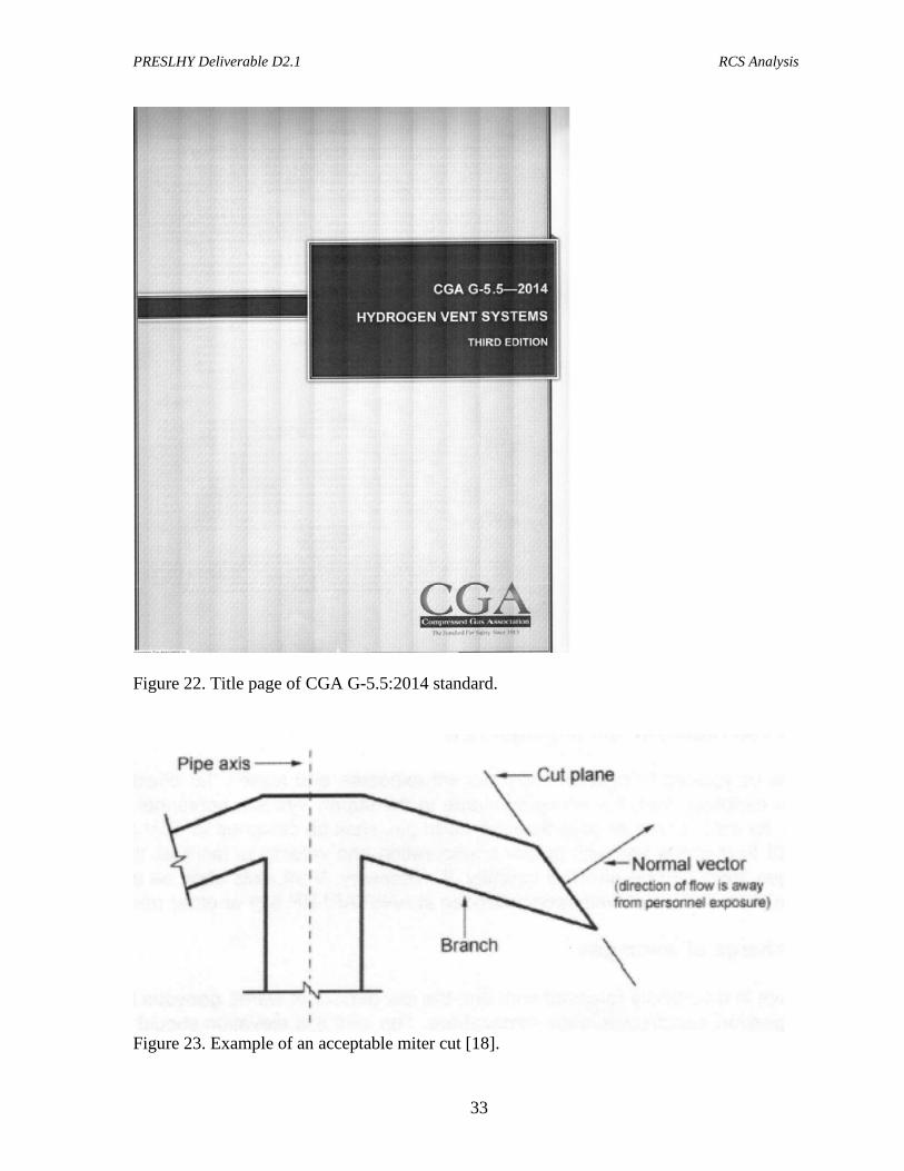
7.2 CGA G-5.5 Hydrogen Vent Systems In 2014 CGA published an updated (3rd edition) G-5.5 standard for hydrogen vent stack systems [18]. For convenience, the title page of CGS G-5.5:2014 is shown on Figure 22. It now specifically highlights vents stack designs recommended for hydrogen use and those that are not. It also gives an example of the recommended miter cut for a T-venting shown on Figure 23.
PRESLHY Deliverable D2.1 RCS Analysis
33
Figure 22. Title page of CGA G-5.5:2014 standard.
Figure 23. Example of an acceptable miter cut [18].
PRESLHY Deliverable D2.1 RCS Analysis
34
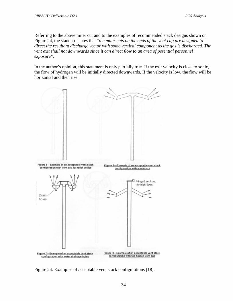
Referring to the above miter cut and to the examples of recommended stack designs shown on Figure 24, the standard states that “the miter cuts on the ends of the vent cap are designed to direct the resultant discharge vector with some vertical component as the gas is discharged. The vent exit shall not downwards since it can direct flow to an area of potential personnel exposure”. In the author’s opinion, this statement is only partially true. If the exit velocity is close to sonic, the flow of hydrogen will be initially directed downwards. If the velocity is low, the flow will be horizontal and then rise.
Figure 24. Examples of acceptable vent stack configurations [18].

PRESLHY Deliverable D2.1 RCS Analysis
35
Figure 25 shows unacceptable vent stack configurations for hydrogen use. The rationale provided by the standard is that “they either direct the hydrogen downward or create an unbalanced thrust that could cause deflection or damage to the vent stack during high velocity discharges.”
Figure 25. Examples of unacceptable vent stack configurations [18]. The standard provides the following guidance regarding Thermal radiation and impingement aspects: “Vent stacks shall be located to prevent impingement exposure and lessen the effects of high temperature and thermal radiation exposure from the escaping plume to the supply system, personnel and adjacent structures.” Regarding the discharge of the cold hydrogen specifically, CGA G-5-5:2014 requires that:
PRESLHY Deliverable D2.1 RCS Analysis
36
• Exist of vent stacks for cold hydrogen gas releases should be at a height that is sufficient to avoid vapour clouds.
• Cold hydrogen vents need to be higher than warm hydrogen vents because the exiting gas can be at a higher density than the ambient air and could cause the hydrogen to accumulate.
7.3 EIGA Code of Practice for Liquid Hydrogen EIGA’s (European Industrial Gas Association) Code of Practice “Safety in Storage. Handling and Distribution of Liquid Hydrogen” was published in 2002 [19]. For convenience, the title page of EIGA Doc 06/02/E is shown on Figure 26.
Figure 26. Title page of EIGA Code of Practice for liquid hydrogen.
PRESLHY Deliverable D2.1 RCS Analysis
37
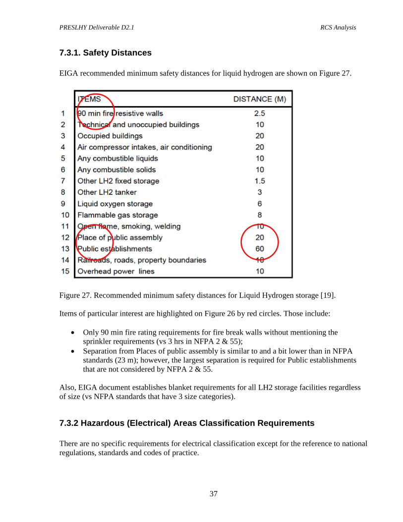
7.3.1. Safety Distances EIGA recommended minimum safety distances for liquid hydrogen are shown on Figure 27.
Figure 27. Recommended minimum safety distances for Liquid Hydrogen storage [19]. Items of particular interest are highlighted on Figure 26 by red circles. Those include:
• Only 90 min fire rating requirements for fire break walls without mentioning the sprinkler requirements (vs 3 hrs in NFPA 2 & 55);
• Separation from Places of public assembly is similar to and a bit lower than in NFPA standards (23 m); however, the largest separation is required for Public establishments that are not considered by NFPA 2 & 55.
Also, EIGA document establishes blanket requirements for all LH2 storage facilities regardless of size (vs NFPA standards that have 3 size categories).
7.3.2 Hazardous (Electrical) Areas Classification Requirements There are no specific requirements for electrical classification except for the reference to national regulations, standards and codes of practice.
PRESLHY Deliverable D2.1 RCS Analysis
38
7.3.3. Hydrogen Vent Stack Requirements EIGA document gives specific instruction on the height of the vent stack: “The height of the vent stack outlet should be either 7 metres above ground level or 3 metres above the top of the tank whichever is the greater for protection of the operating personnel and equipment.” It also makes a specific guidance in regards to vapour clouds: “When siting an installation, due consideration shall be given to the possibility of the movement of vapour clouds, originating from spillage or venting; in addition wind direction and the topography shall be taken into account.”
7.3.4 LH2 Spill Mitigation and Control EIGA document prescribes avoidance of pooling similar to NFPA standards: “Dykes, diversion curbs or grading shall be used to ensure that liquid leakage from adjacent combustible liquid or liquid oxygen storages installed at a higher level than the liquid hydrogen storage, is discouraged from accumulating within 15 metres of the liquid hydrogen storage. The slope of the ground shall be such as to provide normal surface water drainage.”
7.4 Dutch PGS 35 Guidelines PGS 35 Guidelines “Hydrogen: installations for delivery of hydrogen to road vehicles” was published in April 2015 under Hazardous Substances Publication Series 35, version 1.0 [20]. For convenience, the title page of PGS 35 Guidelines is shown on Figure 28. PGS team 35 included representatives from the government and the business community such as representatives from the authorities (the Association of Interprovincial Authorities (IPO), the Association of Dutch Municipalities (VNG), the Social Affairs and Employment Inspectorate (Inspectorate SZW), the Dutch Fire Service, the business community (VNO-NCW and MKB Nederland) and employees.
PRESLHY Deliverable D2.1 RCS Analysis
39
Figure 28. Title page of PGS 35 Guideline for hydrogen installations. The relevance and value of this document is underscored by the paragraph below cited from the “reason for this Publication”: “In the past, the Dutch Code of Practice NPR 8099:2010 on Hydrogen fuelling stations – Guide for safe application of installations for delivery of hydrogen to vehicles and boats with respect to fire, workplace and environment was available for the construction of hydrogen delivery installations in the Netherlands. This Code of Practice comprised a lot of knowledge relevant to the construction of a hydrogen delivery installation. A tour of safety specialists revealed that they preferred a PGS publication due to the uniformity of regulations that are important in the context of granting licenses and due to the footing and transparency they provide as regards granting licenses for the construction of a hydrogen delivery installation. As regards the necessary physical space, a PGS gives internal safety distances that shall be observed. Thus, a PGS offers a guideline of regulations, requirements and safety distances, enabling licensing procedures for hydrogen delivery installations to be performed in a uniform manner.”
PRESLHY Deliverable D2.1 RCS Analysis
40
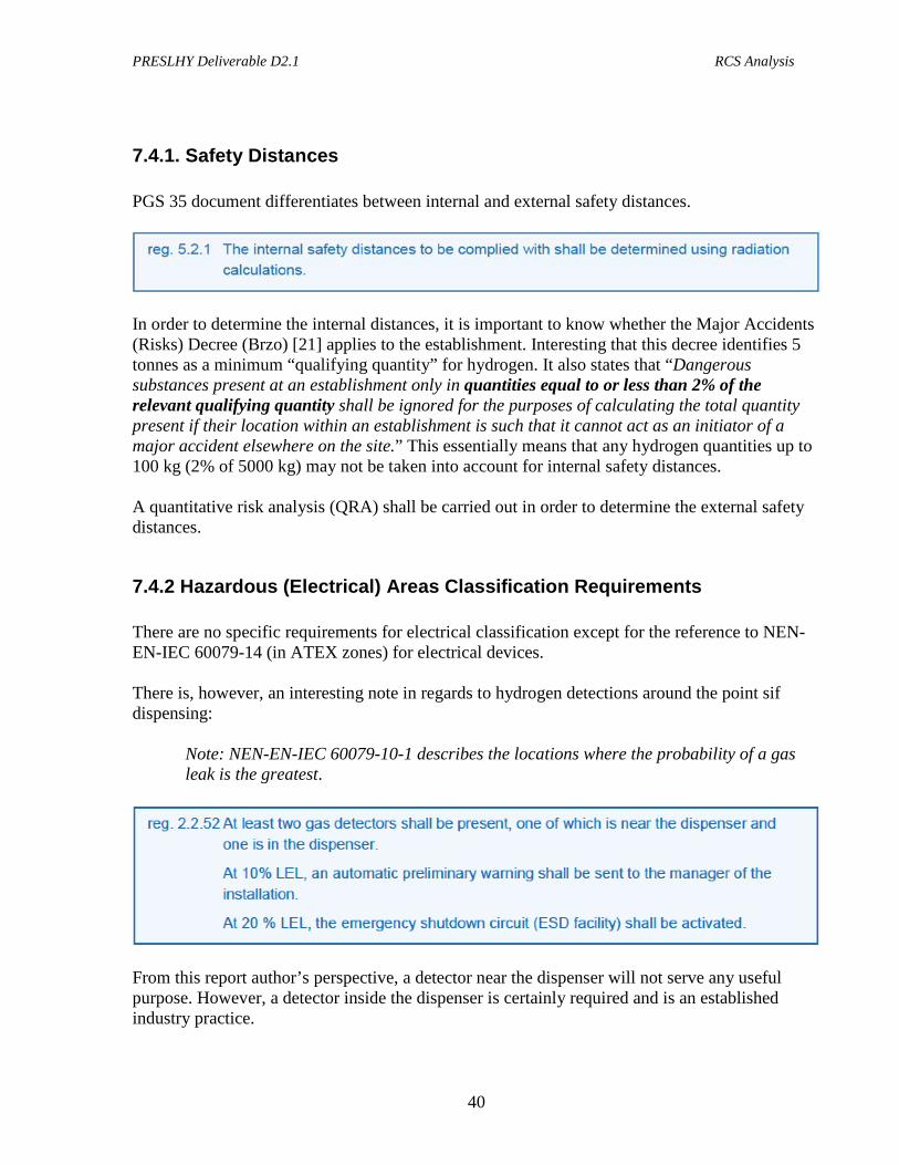
7.4.1. Safety Distances PGS 35 document differentiates between internal and external safety distances.
In order to determine the internal distances, it is important to know whether the Major Accidents (Risks) Decree (Brzo) [21] applies to the establishment. Interesting that this decree identifies 5 tonnes as a minimum “qualifying quantity” for hydrogen. It also states that “Dangerous substances present at an establishment only in quantities equal to or less than 2% of the relevant qualifying quantity shall be ignored for the purposes of calculating the total quantity present if their location within an establishment is such that it cannot act as an initiator of a major accident elsewhere on the site.” This essentially means that any hydrogen quantities up to 100 kg (2% of 5000 kg) may not be taken into account for internal safety distances. A quantitative risk analysis (QRA) shall be carried out in order to determine the external safety distances.
7.4.2 Hazardous (Electrical) Areas Classification Requirements There are no specific requirements for electrical classification except for the reference to NEN-EN-IEC 60079-14 (in ATEX zones) for electrical devices. There is, however, an interesting note in regards to hydrogen detections around the point sif dispensing:
Note: NEN-EN-IEC 60079-10-1 describes the locations where the probability of a gas leak is the greatest.
From this report author’s perspective, a detector near the dispenser will not serve any useful purpose. However, a detector inside the dispenser is certainly required and is an established industry practice.
PRESLHY Deliverable D2.1 RCS Analysis
41
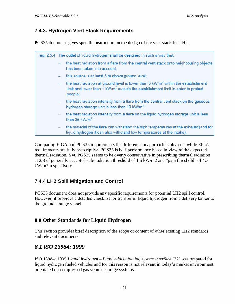
7.4.3. Hydrogen Vent Stack Requirements PGS35 document gives specific instruction on the design of the vent stack for LH2:
Comparing EIGA and PGS35 requirements the difference in approach is obvious: while EIGA requirements are fully prescriptive, PGS35 is half-performance based in view of the expected thermal radiation. Yet, PGS35 seems to be overly conservative in prescribing thermal radiation at 2/3 of generally accepted safe radiation threshold of 1.6 kW/m2 and “pain threshold” of 4.7 kW/m2 respectively.
7.4.4 LH2 Spill Mitigation and Control PGS35 document does not provide any specific requirements for potential LH2 spill control. However, it provides a detailed checklist for transfer of liquid hydrogen from a delivery tanker to the ground storage vessel. 8.0 Other Standards for Liquid Hydrogen This section provides brief description of the scope or content of other existing LH2 standards and relevant documents.
8.1 ISO 13984: 1999 ISO 13984: 1999 Liquid hydrogen – Land vehicle fueling system interface [22] was prepared for liquid hydrogen fueled vehicles and for this reason is not relevant in today’s market environment orientated on compressed gas vehicle storage systems.
PRESLHY Deliverable D2.1 RCS Analysis
42
Its scope includes the following: “This International Standard specifies the characteristics of liquid hydrogen refueling and dispensing systems on land vehicles of all types in order to reduce the risk of fire and explosion during the refueling procedure and thus to provide a reasonable level of protection from loss of life and property. This International Standard is applicable to the design and installation of liquid hydrogen (LH2) fuelling and dispensing systems. It describes the system intended for the dispensing of liquid hydrogen to a vehicle, including that portion of the system that handles cold gaseous hydrogen coming from the vehicle tank, that is, the system located between the land vehicle and the storage tank.”
8.2 ISO 13985: 2006 ISO 13985: 2006 Liquid hydrogen – Land vehicle fuel tanks [23] was prepared for liquid hydrogen fueled vehicles and for this reason, as the standard above, is not relevant in today’s market environment orientated on compressed gas vehicle storage systems. Its scope includes the following: “This International Standard specifies the construction requirements for refillable fuel tanks for liquid hydrogen used in land vehicles as well as the testing methods required to ensure that a reasonable level of protection from loss of life and property resulting from fire and explosion is provided. This International Standard is applicable to fuel tanks intended to be permanently attached to land vehicles.”
8.3 HSL Position Paper HSL Position paper on hazards of liquid hydrogen [24] was published in 2010 per request from the UK Health and Safety Executive “to identify and address issues relating to bulk liquid hydrogen transport and storage and update/develop guidance for such facilities.” “This position paper, the first part of the project, assesses the features of the transport and storage aspects of the refuelling stations that are now being constructed in the UK, compares them to existing guidance, highlights gaps in the regulatory regime and identifies outstanding safety issues. The findings, together with the results of experiments to improve our understanding of the behaviour of liquid hydrogen, will inform the development of the guidance for refuelling facilities.”
PRESLHY Deliverable D2.1 RCS Analysis
43
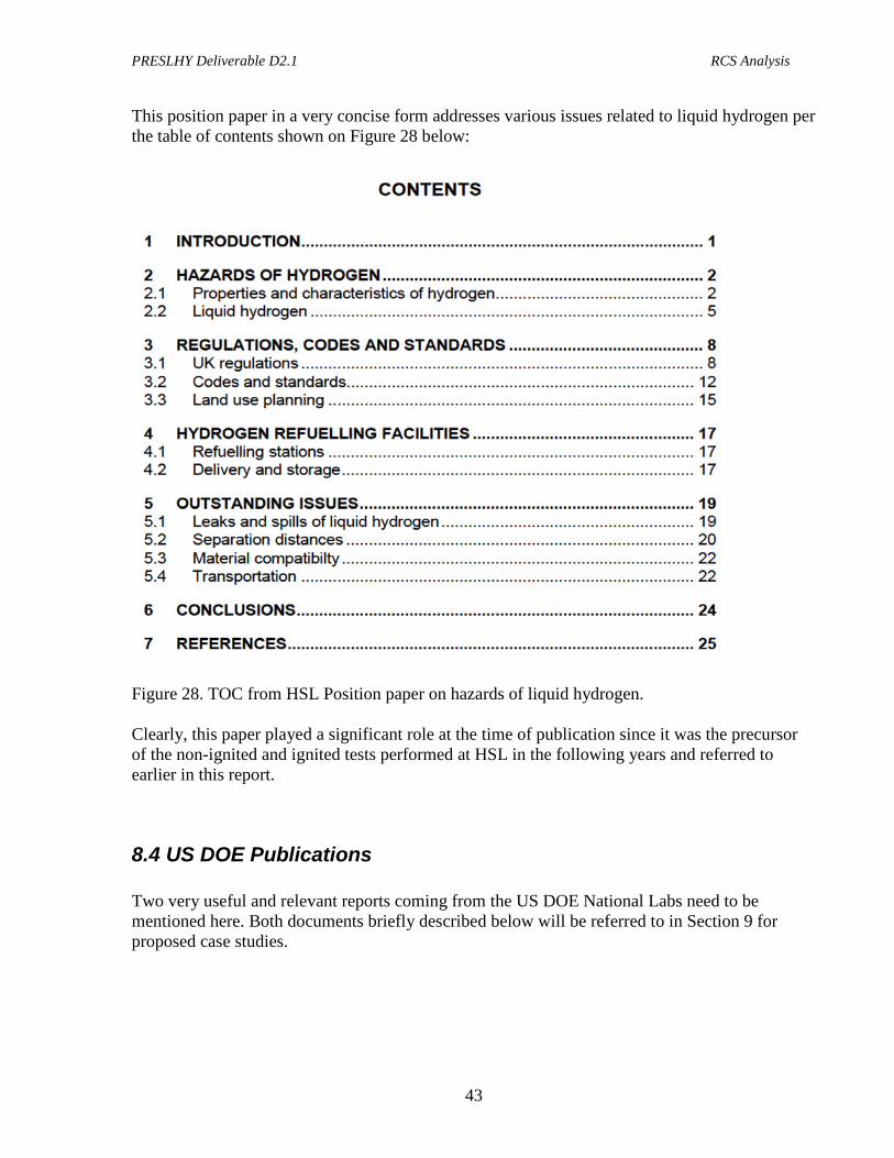
This position paper in a very concise form addresses various issues related to liquid hydrogen per the table of contents shown on Figure 28 below:
Figure 28. TOC from HSL Position paper on hazards of liquid hydrogen. Clearly, this paper played a significant role at the time of publication since it was the precursor of the non-ignited and ignited tests performed at HSL in the following years and referred to earlier in this report.
8.4 US DOE Publications Two very useful and relevant reports coming from the US DOE National Labs need to be mentioned here. Both documents briefly described below will be referred to in Section 9 for proposed case studies.
PRESLHY Deliverable D2.1 RCS Analysis
44
8.4.1 Hydrogen Technologies Safety Guide Hydrogen Technologies Safety Guide was developed and published by National Renewable Energy Lab (NREL) in January 2015 [25]. Similar to HSL Position paper mentioned above, it discusses hydrogen hazards as well as in great detail relevant codes and standards, but with US focus. Its particular value for PRESLHY project is the Permit Example where a layout of a typical hydrogen station is presented, including both compressed and liquid hydrogen storage, with the required separation distances as prescribed by NFPA 2.
8.4.2 Safety, Codes and Standards for Hydrogen Installations The report Safety, Codes and Standards for Hydrogen Installations: Hydrogen Fueling System Footprint Metric Development was developed and published Sandia National Labs (Sandia) in April 2014 [26]. The significant value of this report is the demonstration how footprint metrics can effectively demonstrate the impact on installation code requirements on the land footprint required for placement of a hydrogen station. The abstract of the report states: “The development, implementation, and advancement of meaningful codes and standards is critical to enable the effective deployment of clean and efficient fuel cell and hydrogen solutions in the energy technology marketplace. Metrics pertaining to the development and implementation of safety knowledge, codes, and standards are important to communicate progress and inform future R&D investments. This document describes the development and benchmarking of a metric specific to the development of hydrogen specific codes relevant for hydrogen refueling stations: “number of fueling stations that can readily accept hydrogen”.” The report includes very useful exercise of overlaying separation distances requirements from NFPA 2 over existing (real world) sites selected for hydrogen station placement. Some of the material from this report will be used in the next Section. 9.0 Examples of Potential Case Studies The best way for a PNR project to be relevant to the real world is to demonstrate its findings for real world applications, such as, for example, a hydrogen refueling station. In this regard, the following two case studies are proposed. They are based on the information provided in the US DOE reports as well as EIGA Code of Practice. Important note: the proposed case studies are examples. Thus, they can be modified with inclusion of other relevant information. Also, other similar case studies could be added to the project portfolio.
PRESLHY Deliverable D2.1 RCS Analysis
45
The approach will be to compare and / or overlay the numbers coming from the existing documents vs hazard distances obtained within the PRN scope of work (modeling and experiments).
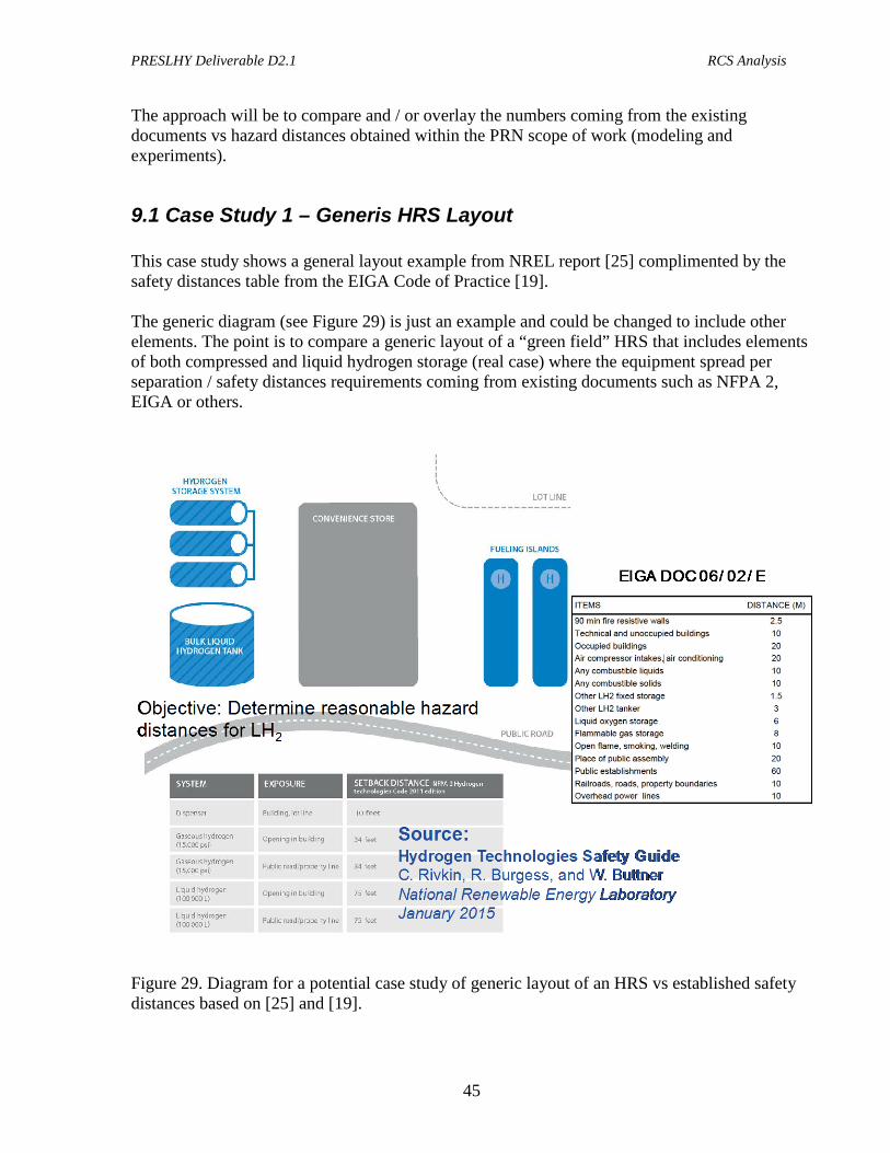
9.1 Case Study 1 – Generis HRS Layout This case study shows a general layout example from NREL report [25] complimented by the safety distances table from the EIGA Code of Practice [19]. The generic diagram (see Figure 29) is just an example and could be changed to include other elements. The point is to compare a generic layout of a “green field” HRS that includes elements of both compressed and liquid hydrogen storage (real case) where the equipment spread per separation / safety distances requirements coming from existing documents such as NFPA 2, EIGA or others.
Figure 29. Diagram for a potential case study of generic layout of an HRS vs established safety distances based on [25] and [19].
PRESLHY Deliverable D2.1 RCS Analysis
46
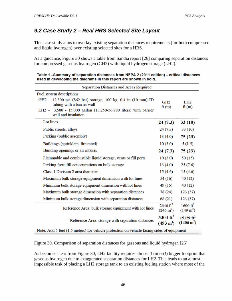
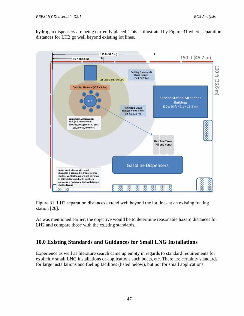
9.2 Case Study 2 – Real HRS Selected Site Layout This case study aims to overlay existing separation distances requirements (for both compressed and liquid hydrogen) over existing selected sites for a HRS. As a guidance, Figure 30 shows a table from Sandia report [26] comparing separation distances for compressed gaseous hydrogen (GH2) with liquid hydrogen storage (LH2).
Figure 30. Comparison of separation distances for gaseous and liquid hydrogen [26]. As becomes clear from Figure 30, LH2 facility requires almost 3 times(!) bigger footprint than gaseous hydrogen due to exaggerated separation distances for LH2. This leads to an almost impossible task of placing a LH2 storage tank to an existing fueling station where most of the
PRESLHY Deliverable D2.1 RCS Analysis
47
hydrogen dispensers are being currently placed. This is illustrated by Figure 31 where separation distances for LH2 go well beyond existing lot lines.
Figure 31. LH2 separation distances extend well beyond the lot lines at an existing fueling station [26]. As was mentioned earlier, the objective would be to determine reasonable hazard distances for LH2 and compare those with the existing standards. 10.0 Existing Standards and Guidances for Small LNG Installations Experience as well as literature search came up empty in regards to standard requirements for explicitly small LNG installations or applications such boats, etc. There are certainly standards for large installations and fueling facilities (listed below), but not for small applications.
PRESLHY Deliverable D2.1 RCS Analysis
48
The only document specific to small scale applications that appeared on the radar screen is the Small LNG report produced by the International Gas Union in 2015 [27]. Its title page is shown for convenience on Figure 32.
Figure 32. Title page of the Small Scale LNG report [27].
PRESLHY Deliverable D2.1 RCS Analysis
49
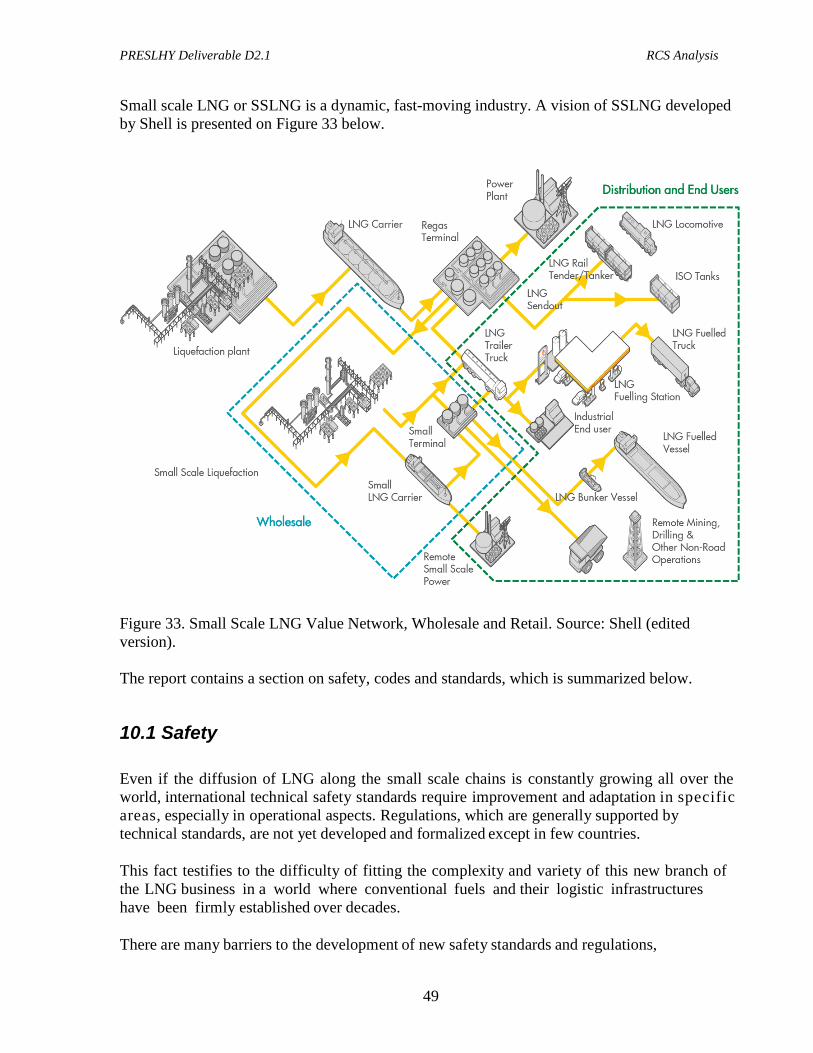
Small scale LNG or SSLNG is a dynamic, fast-moving industry. A vision of SSLNG developed by Shell is presented on Figure 33 below.
Figure 33. Small Scale LNG Value Network, Wholesale and Retail. Source: Shell (edited version). The report contains a section on safety, codes and standards, which is summarized below.
10.1 Safety Even if the diffusion of LNG along the small scale chains is constantly growing all over the world, international technical safety standards require improvement and adaptation in specific areas, especially in operational aspects. Regulations, which are generally supported by technical standards, are not yet developed and formalized except in few countries. This fact testifies to the difficulty of fitting the complexity and variety of this new branch of the LNG business in a world where conventional fuels and their logistic infrastructures have been firmly established over decades. There are many barriers to the development of new safety standards and regulations,

PRESLHY Deliverable D2.1 RCS Analysis
50
including:
o The cryogenic nature of LNG. LNG is the first and only cryogenic fuel offered to a large scale market and this implies very peculiar technical issues. For example, no other conventional fuel produces boil off;
o The international characteristics of the LNG market that lead to a need for “global”
or at least “regional” standardized interfaces. An example is the newly built small to medium sized LNG carriers, some with pressurised tanks, and others with conventional tanks. Both of them will need to dock at the same terminal, possibly the same as conventional large size LNG carriers;
o The difficulty of integrating new infrastructure into active areas, like ports, often
congested, close to urban areas, with possible safety issues, and usually already strictly regulated by local, national or even supra-national laws;
o The need to create a common ground of awareness of the small scale LNG
characteristics and potential among industrial stakeholders of different nature (LNG suppliers, technology providers, users), governmental entities and the public. In addition, the number of experts that currently know how LNG can be safely transported, transferred, managed and stored in the small scale environment is limited if compared to the envisaged amplitude of the market and this doesn’t help a fast harmonization;
o LNG facilities are often at the interface between offshore and onshore. Marine
facilities generally relate to international rules whereas onshore facilities are based on national regulations.
o The global nature of the small scale LNG development. In many countries, pilot
projects/initiatives have been developed with success. Each success tends to create local (sometimes “strictly local”) know-how that can be conflicting with the know-how developed elsewhere. An example: screwed connections for hoses are widely used but fast connecting couplings are also proposed to the market. Will both standards have to coexist and how?
o As the potential of Small Scale LNG is not yet fully understood and defined, it
becomes quite difficult to define some of the necessary standards and the required regulations. For instance, currently no one is now providing a LNG transfer service between vessels during navigation but this kind of operation can be considered usual for conventional fuels; is there a need to start thinking of international standards for this kind of transfer or is it too early?
Even if the size and complexity of the described barriers is quite high, some scattered and initial evolutions have already started. They can be summarized in few lines:
o Development of local and national regulations in the frontrunner countries;
PRESLHY Deliverable D2.1 RCS Analysis
51
o Supranational/federal interest to create common standards and regulations;
o Interest of certifying bodies in the development of specific guidelines.
The common fundamental factor of these evolution lines is safety. In the following paragraphs international standards and local regulations will be discussed in general terms and specific cases will be presented from some of the countries that are more advanced in introducing LNG and from other countries where similar efforts are ongoing.
10.2 Technical Standards Watching the recent evolutions in small scale LNG, it can be noted that the development of new technical standards for plants and components and the operative procedures, have been based on the adaptation of standards commonly used in the well-developed large scale LNG industry or in some specific niches as, for instance, the LNG peak shaving plants. A key importance can be attached to the LNG terminals that are becoming the heart of the development of the first small scale LNG initiatives in those regions where such terminals were already operating. In the past two decades, these plants have spread out in all the continents, allowing the local industries and authorities to come into contact with LNG and to build the first nuclei of knowledge. In the producing countries, a similar role is fulfilled by the LNG liquefaction plants. In this respect, organizations like The Society of International Gas Carrier and Terminal Operators (SIGTTO) and the new born Society for Gas as a Marine Fuel (SGMF) have an important role in establishing a base level of harmonization. Another important source of know-how and experience, if not directly of standards and procedures, is the cryogenic gas production and processing industry and, secondly, the wide area of the hazardous substances. Other standards and guidelines are coming from the maritime side of the LNG business: International Maritime Organization (IMO) is very active in producing practical high level guidelines, both on the environmental and safety side. ISO is also discussing new draft standards covering the areas of main interest for small scale LNG. Up to now, the approach of ISO has been to target high level guidance and standards rather than developing detailed comprehensive frameworks. Therefore, few documents have been issued in its final release but many more are under development in the working groups, as shown in the next sub-section. 10.3 List of Technical Standards for LNG Here is a list of selected international standards, usually not specifically developed for small scale LNG uses, but at least partially applicable to this new industrial environment and that constitute the basis for any related project.
PRESLHY Deliverable D2.1 RCS Analysis
52
NFPA 59A- Standard for the Production, Handling and Storage of Liquefied Natural Gas (LNG) 2013 edition This US National Fire Protection Association standard applies to the location, design, construction, maintenance and operation of all facilities that liquefy, store, vaporize and handle natural gas and deals with the training of personnel involved with LNG. EN 1473:2007 Installation and Equipment for LNG - Design of Onshore Installations This European Standard provides guidelines for the design, construction and operation of all onshore liquefied natural gas installations, including those for the liquefaction, storage, vaporization, transfer and handling of LNG. EN 1474-1:2008 - Installation and Equipment for LNG – Design and testing of marine transfer systems – Part 1: Design and testing of transfer arms (Being revised as ISO/DIS 16904) This European Standard specifies the design, minimum safety requirements and inspection and testing procedures for LNG transfer arms intended for use on conventional onshore LNG terminals. It also covers the minimum requirements for safe LNG transfer between ship and shore. Although the requirements for remote control power systems are covered, the standard does not include all the details for the design and fabrication of standard parts and fittings associated with transfer arms. EN 1474-2:2008 - Installation and Equipment for LNG – Design and testing of marine transfer systems – Part 2: Design and testing of transfer hoses This European Standard provides general guidelines for the design, material selection, qualification, certification, and testing details for LNG transfer hoses for offshore transfer or on coastal weather-exposed facilities for aerial, floating and submerged configurations or a combination of these. While this European Standard is applicable to all LNG hoses, there may be further specific requirements for floating and submerged hoses. The transfer hoses will be designed to be part of transfer systems (fitted with ERS, QCDC, handling systems, hydraulic and electric components etc,). EN 1474-3:2008 - Installation and Equipment for LNG - Design and testing of marine transfer Systems – Part 3: Offshore transfer systems This European Standard gives general guidelines for the design of LNG transfer systems intended for use on offshore transfer facilities or on coastal weather exposed transfer facilities. The transfer facilities considered may be between floating units, or between floating and fixed units. The specific component details of the LNG transfer systems are not covered by this European Standard. ISO 28460:2010 – Installation and equipment for LNG Ship-to-shore interface and port operations This standard specifies the requirements for ship, terminal and port service providers to ensure the safe transit of an LNG carrier (LNGC) through the port area and the safe and efficient transfer of its cargo.
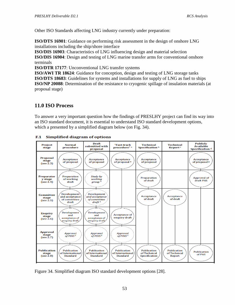
PRESLHY Deliverable D2.1 RCS Analysis
53
Other ISO Standards affecting LNG industry currently under preparation: ISO/DTS 16901: Guidance on performing risk assessment in the design of onshore LNG installations including the ship/shore interface ISO/DIS 16903: Characteristics of LNG influencing design and material selection ISO/DIS 16904: Design and testing of LNG marine transfer arms for conventional onshore terminals ISO/DTR 17177: Unconventional LNG transfer systems ISO/AWI TR 18624: Guidance for conception, design and testing of LNG storage tanks ISO/DTS 18683: Guidelines for systems and installations for supply of LNG as fuel to ships ISO/NP 20088: Determination of the resistance to cryogenic spillage of insulation materials (at proposal stage) 11.0 ISO Process To answer a very important question how the findings of PRESLHY project can find its way into an ISO standard document, it is essential to understand ISO standard development options, which a presented by a simplified diagram below (on Fig. 34).
Figure 34. Simplified diagram ISO standard development options [28].
PRESLHY Deliverable D2.1 RCS Analysis
54
ISO/ TC 197 Hydrogen technologies developed a safety standard document – technical report ISO 15916:2015 Basic considerations for safety of hydrogen systems. So, one option would be to add the findings of PRESHLY project to this report in its next revision. However, the author of this report being the current Chair of ISO/TC 197 recommends setting up a new Working Group via a NWIP (New Work Item Proposal) to develop a separate Technical Report specific to liquid hydrogen applications. Such NWIP can be submitted via a normal ISO process through any ISO/TC 197 P-member mirror committee during the first year of the project. This will ensure that the balloting and consecutive set up of the Working Group (WG) will be set up by the 2nd year of the project, thus, leaving 24 months for the new Technical Report (TR) development as PRESHLY findings come along. The completion of the TR can be conducted within the following 12 months after the completion of PRESHLY ensuring that the project results are properly analyzed and summarized for the purpose of the TR. Hence, the project management (meaning PRESLHY project partners) needs to consciously allocate necessary resources to make sure that the ISO project is fully supported from the beginning (development of the NWIP and setting up of the WG) to the completion and publication of the TR. Based on experience, it is with 100% certainty can be stated that if such resources are not allocated, the ISO TR will not be completed. 12.0 Summary and Recommendations This report provided a comprehensive overview of most relevant standards and best practices for the PNR project on liquid hydrogen. Four focus areas from RCS perspective have been recommended:
1. Safety / separation distances 2. Hazardous area 3. LH2 venting, and 4. Spill control.
To ensure that PRESLHY results are relevant to industry, two case studies have been recommended. The objective would be to determine reasonable hazard distances for liquid hydrogen installations and then compare them with the requirements of the published standards reviewed within this report. Last but not least, to make PRESLHY findings find their way to ISO (or any other SDO), the project partners must allocate adequate resources to make sure that a standard development project is properly led and supported from beginning to end leading to a standard document publication. Technical Report (TR) is proposed as the most suitable format of such document.
PRESLHY Deliverable D2.1 RCS Analysis
55
References
1. Linde BMW brochure promoting cryo-compressed technology, 2017. 2. PRESLHY application, 2017. 3. California Fuel Cell Partnership, 2010. 4. A.V. Tchouvelev private report, 2016. 5. Buttner, W.J., Rivkin, C., Schmidt, K., Hartmann, K., Wright, H., and Weidner, E.,
Ciotti, M. Empirical Profiling of Cold Hydrogen Plumes formed from Venting of LH2 Storage Vessels, NREL/CP-5400-68771 November 2017.
6. US DOE, PNNL administered website, https://h2tools/lessons. 7. Lowesmith, B.J., Hankinson, G. and Chynoweth, S. Safety Issues of the Liquefaction,
Storage and Transportation of Liquid Hydrogen: Studies in the IDEALHY Project, Proceedings of ICHS2013, Brussels, Sept 2013.
8. M. Royle and D. Willoughby. HSL Liquid Hydrogen Spills – Initial Trials. Presentation at the expert meeting of IEA HIA Task 31, May 2010.
9. J.E. Hall, P. Hooker, D. Willoughby. Ignited releases of liquid hydrogen: Safety considerations of thermal and overpressure effects. IJHE, 39 (2014), 20547-20553.
10. Ignited releases of liquid hydrogen, Prepared by the Health and Safety Laboratory for the Health and Safety Executive 2014, RR987.
11. Cassut L.H. et al. A Study of the Hazards in the Storage and Handling of Liquid Hydrogen. Advances in Cryogenic Engineering, 5: 55-61, 1960.
12. Witcofski R.D. and Chirivella J.E., (1984), “Experimental and analytical analyses of the mechanisms governing the dispersion of flammable clouds formed by liquid hydrogen spills”, Int. J. Hydrogen Energy, Vol 9., No 5, pp 425-435.
13. K. Verfondern and B. Dienhart, (1997), “Experimental and theoretical investigation of liquid hydrogen pool spreading and vaporization”, Int. J. Hydrogen Energy, Vol. 22, No 7, pp. 649-660.
14. A. D. Little Inc., (1960), “An Investigation of Hazards Associated with the Storage and Handling of Liquid Hydrogen”, Final Report, Contract No AF-18 (600)-1687 (AD-324/94).
15. Zabetakis M.G. et al. Explosion Hazards of Liquid Hydrogen. Advances in Cryogenic Engineering, 6: 185-194, 1961.
16. Zabetakis M.G. and Burgess D.S. Research on the Hazards Associated with the Production and Handling of Liquid hydrogen. Report WADD TR 60-141, Wright Air Development Division, USA, 1960.
17. Urano Y. et al. Hazards of Burning Liquefied Hydrogen. National Chemical Laboratory for Industry, 81: 143-157, 1986.
18. CGA G-5.5 Hydrogen Vent Systems, Third edition, 2014. 19. EIGA Code of Practice “Safety in Storage. Handling and Distribution of Liquid
Hydrogen”, Doc 06/02/E, 2002. 20. PGS 35 Guidelines “Hydrogen: installations for delivery of hydrogen to road vehicles”.
Hazardous Substances Publication Series 35, version 1.0 (April 2015). 21. Major Accidents (risks) Decree 1999, The Netherlands. 22. ISO 13984: 1999 Liquid hydrogen – Land vehicle fueling system interface. ISO, 1999. 23. ISO 13985: 2006 Liquid hydrogen – Land vehicle fuel tanks. ISO, 2006.
PRESLHY Deliverable D2.1 RCS Analysis
56
24. Position paper “Hazards of liquid hydrogen”, HSL, 2010. 25. C. Rivkin, R. Burgess, and W. Buttner. Hydrogen Technologies Safety Guide, NREL
Technical Report, NREL/TP-5400-60948, January 2015. 26. A.P. Harris, Daniel E. Dedrick, Chris LaFleur, Chris San Marchi. Safety, Codes and
Standards for Hydrogen Installations: Hydrogen Fueling System Footprint Metric Development, Sandia Report SAND2014-3416, April 2014.
27. Small Scale LNG. Report by the International Gas Union, June 2015. 28. Simplified diagram of options. ISO Directives 2015. 29. ISO/TR 15916:2015 Basic considerations for safety of hydrogen systems, ISO 2015.