reinforced eps core panel system - bmtpcbmtpc.org/datafiles/cms/file/pdf_files/34_pac-eps.pdf ·...
TRANSCRIPT

`
Reinforced
EPS Core
Panel System
User should check the
validity of the Certificate by contacting Member
Secretary, BMBA at BMTPC
or the Holder of this
Certificate.
Performance Appraisal
Certificate No.
PAC No 1020-S/2015
Issue No. 01
Date of Issue: 16.11.2015
Name and Address of Certificate Holder:
M/s Jindal Steel & Power
Ltd.1st Floor, Tower – B,
Jindal Centre, Plot No. 2,
Sector – 32,
Gurgaon – 122 001
Building Materials & Technology Promotion Council Ministry of Housing & Urban Poverty Alleviation
Government of India
Core 5A, First Floor, India Habitat Centre,
Lodhi Road, New Delhi – 110 003 Tel: +91-11-2463 8096, 2463 8097; Fax: +91-11-2464 2849
E-mail: [email protected] Web Site: http://www.bmtpc.org

2
CONTENTS
PART 1 CERTIFICATION ……………………………………………………… …… 3 1.1 Certificate Holder ……………………………………………………………… 3 1.2 Description of System …..……………………………………………………. 3 1.3 Types of Panels ………………………………………………………………. 4 1.4 Assessment ………………………..………………………………………….. 8 1.5 Uses of the System ……………………………………………………… …… 8 1.6 Conditions of Certification ………………………………………………. …… 9 1.7 Certification…………………………………………………………………… 10 PART 2 CERTIFICATE HOLDER’S TECHNICAL SPECIFICATION..…………. 10 2.1 General ………………………………………………………………………… 10 2.2 Specifications for the System ………………………………………….……. 10 2.3 Production Process ………………………………………………………….... 11 2.4 Design Consideration …………………………………………………... …… 11 2.5 Installation Procedure ………………………………………………………… 13 2.6 Machinery Involved …………………………………………………………… 15 2.7 Tools Required ………………………………………………………………… 15 2.8 Inspection and Testing …………………………………………………….…… 16 2.9 Handling & Storage and Marking & Identification …………………………… 16 2.10 Good Practices………………………… ……………………………………… 17 2.11 Maintenance requirements …………………………………………….…….. 17 2.12 Skills / training needed for installation ………………………………............ 17 2.13 Health and Safety Measures ………………………………………………… 17 2.14 Guarantees / Warranties provided by the PAC holder ………………………. 17 2.15 Service provided by the PAC holder to the customer ……………………… 17 2.16 Manual …………………………………………………………………………… 17 2.17 Responsibility …………………………………………………………………… 18 PART 3 BASIS OF ASSESSMENT AND BRIEF DESCRIPTION OF ASSESSMENT PROCEDURE ………………………………………………………………………… 18 3.1 Assessment …………………………………………………………………….. 18 3.2 Laboratory tests done for assessment …………………………….………… 18 3.3 Usage of the System …………………………………………………………… 20 PART 4 STANDARD CONDITIONS …………………………………………............ 22 PART 5 LIST OF STANDARDS AND CODES USED IN ASSESSMENT ………. 24 CERTIFICATION ……………………………………………………………………….. 25 PART 6 ABBREVIATIONS ……………………………………………………………. 26 PERFORMANCE APPRAISAL CERTIFICATIONS SCHEME – A BRIEF ……… 27 ANNEX I QAP …………………………………………………………………………… 28 ANNEX II Drawings…………………………………………………………………….. 29 ANNEX III Design Philosophy…….………………………………………………… 42

3
PART 1 CERTIFICATION
1.1 Certificate Holder: Factory
M/s Jindal Steel & Power Ltd., Chhendipada Road, SH-63, AHPO: Jindal Nagar,
Distt. Angul, Odisha – 759111 Corporate Office M/s Jindal Steel & Power Ltd., 1st Floor, Tower – B, Jindal Centre, Plot No. 2, Sector – 32, Gurgaon – 122 001
1.2 Description of System 1.2.1 Name of System - Reinforced EPS Core Panel System 1.2.2 Brand Name –Reinforced EPS Wall Panel 1.2.3 Brief Description – Expanded Polystyrene Core Panel System is a
factory produced panel system for the construction of low rise buildings upto G+3 and as filler walls in high rise RCC and steel frame buildings. In this technique a core of undulated polystyrene is covered with interconnected zinc coated welded wire mesh on both sided reinforcement and shortcrete concrete.
The panels are finished on site by pouring concrete (double panel, floors and stairs) and spraying concrete to realise the following different elements of the system:
Vertical Structural Walls
Horizontal Structural elements
Cladding elements

4
1.3 Types of Panels 1.3.1 Single Bearing Panel
Used as Load Bearing Wall
Fig. 1 Mesh Width : 1235 mm
Longitudinal wires : ø 2.5/3.0 mm @ 80 mm c/c (max) Transverse wires : ø 2.5/3.0 mm @ 75 mm c/c (max) Connectors & cross wire : ø 3.0 mm @ 150 mm c/c EPS Density : ≤ 15 kg/m3 Thickness : 50 mm to 160 mm Wave Depth : 15 mm
5
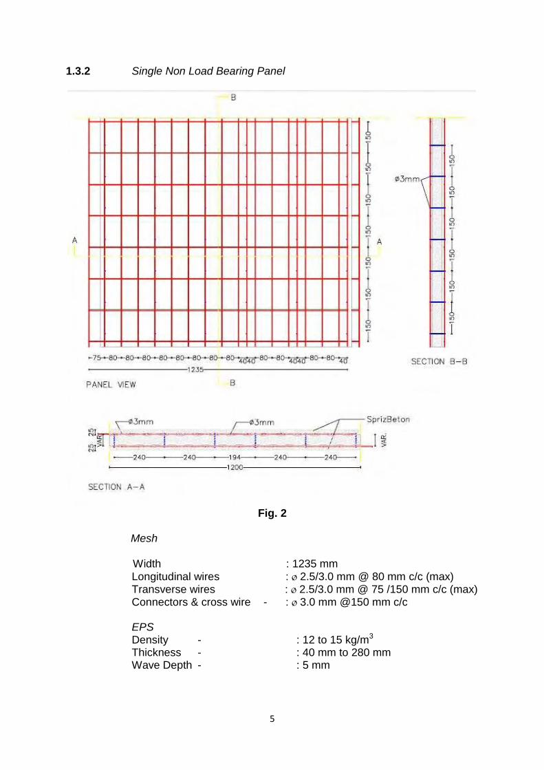
1.3.2 Single Non Load Bearing Panel
Fig. 2
Mesh Width : 1235 mm
Longitudinal wires : ø 2.5/3.0 mm @ 80 mm c/c (max) Transverse wires : ø 2.5/3.0 mm @ 75 /150 mm c/c (max) Connectors & cross wire - : ø 3.0 mm @150 mm c/c EPS Density - : 12 to 15 kg/m3 Thickness - : 40 mm to 280 mm Wave Depth - : 5 mm

6
1.3.3 Single Floor Panel
Used as floors or roofs span upto 5 m x 5m and supported by the walls in all the sides. The panels are finished on site by 50 mm of casted concrete in upper side and 30 mm of projected plaster in the lower side.
Fig. 3
EPS Width : 1200 mm
Thickness : 80 to 160 mm
Density : ≮ 15Kg/m3
Mesh Width : 1235 mm Longitudinal wires : 2.5 / 3.0 mm ø @ 80 mm c/c Transverse wires : 2.5 / 3.0 mm ø @ 75 mm c/c Connectors & cross wire : ø 3.0 mm @ 150 mm c/c

7
1.3.4 Two Pot Floor Panel
Fig. 4
With span up to 9 m, these panels are characterized by the presence of joist.
The joists are reinforced on site by the steel bars according to the structural verification and are finished by 40 mm of casted concrete (M25) on the upper side and 25 mm of projected plaster (M15) in the lower side.
EPS Sheet Width : 1200 mm

8
Density : 15 Kg/m3
Mesh Width : 1235 mm Longitudinal wires : ø 2.5 / 3.0 mm @ 80 mm c/c Transverse wires : ø 2.5 / 3.0 mm @ 75 mm c/c Connectors : ø 3.0 mm @ 150 mm c/c 1.4 Assessment 1.4.1 Scope of Assessment 1.4.1.1 Scope of assessment included conformity of the manufactured panels to the specified requirements for use in building construction as
i. Load bearing wall panels ii. Non load bearing wall panels iii. Shear wall iv. Floor / roof slab
The structural design for each specific specification structure is the responsibility of the building designer.
1.4.2 Basis of Assessment
Assessment of the suitability of Reinforced EPS Panel Manufactured at M/s Jindal Steel & Power Ltd., Angul, Odisha is based on
i. Inspection of the factory for production and quality assurance of
the raw material & finished products as per as specified specification.
ii. Inspection of buildings constructed / being constructed using reinforced EPS panel and feedback from the users.
iii. Verification of design detail for panels. 1.5 Use of EPS Core Panel and its Limitations 1.5.1 The panels shall be used as:
i. As load bearing walling in buildings ii. As non- load bearing wall panels iii. As partition infill wall in multi storey framed buildings iv. As floor / roof slabs
1.5.2 Durability
The certificate Holder shall provide necessary structural warranty ensuring durability of the system to the user, on demand.
9
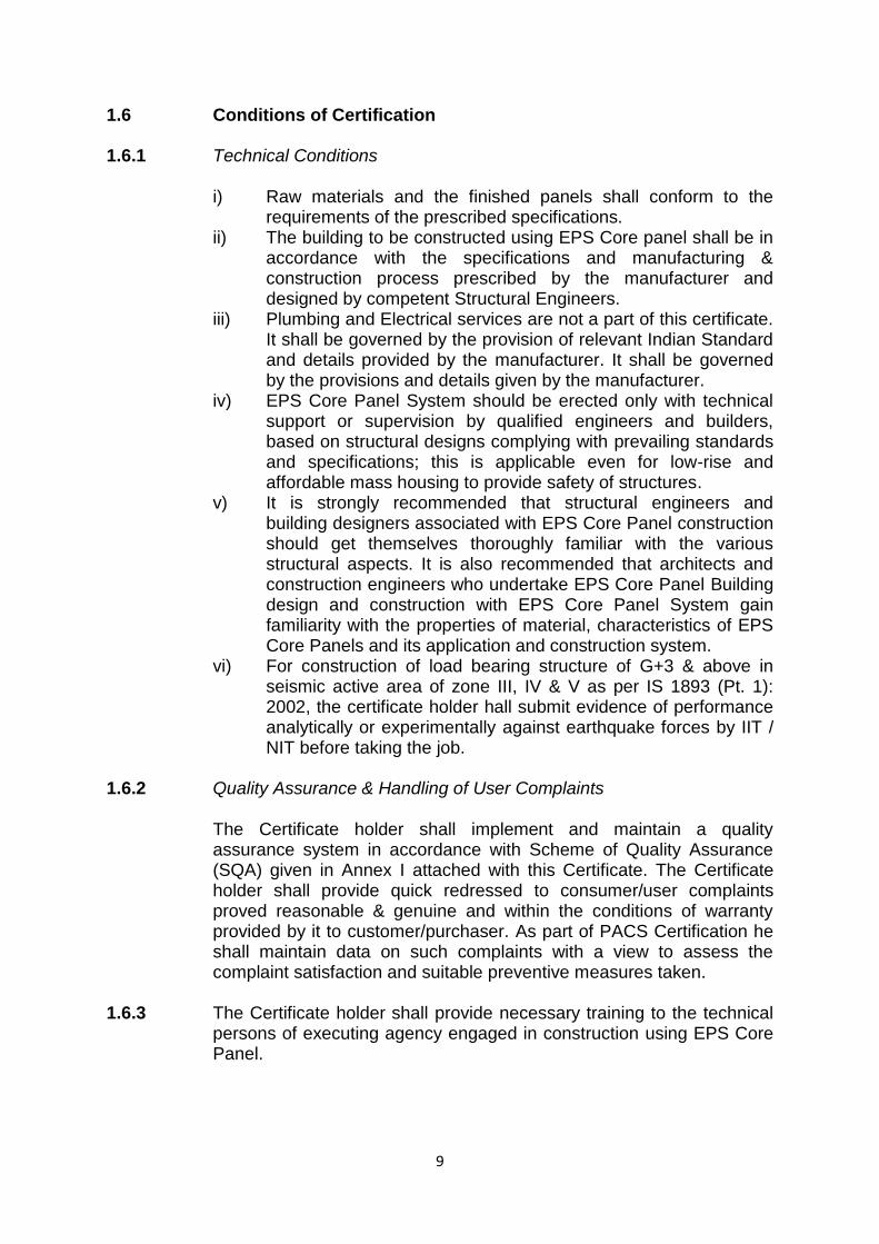
1.6 Conditions of Certification 1.6.1 Technical Conditions
i) Raw materials and the finished panels shall conform to the requirements of the prescribed specifications.
ii) The building to be constructed using EPS Core panel shall be in accordance with the specifications and manufacturing & construction process prescribed by the manufacturer and designed by competent Structural Engineers.
iii) Plumbing and Electrical services are not a part of this certificate. It shall be governed by the provision of relevant Indian Standard and details provided by the manufacturer. It shall be governed by the provisions and details given by the manufacturer.
iv) EPS Core Panel System should be erected only with technical support or supervision by qualified engineers and builders, based on structural designs complying with prevailing standards and specifications; this is applicable even for low-rise and affordable mass housing to provide safety of structures.
v) It is strongly recommended that structural engineers and building designers associated with EPS Core Panel construction should get themselves thoroughly familiar with the various structural aspects. It is also recommended that architects and construction engineers who undertake EPS Core Panel Building design and construction with EPS Core Panel System gain familiarity with the properties of material, characteristics of EPS Core Panels and its application and construction system.
vi) For construction of load bearing structure of G+3 & above in seismic active area of zone III, IV & V as per IS 1893 (Pt. 1): 2002, the certificate holder hall submit evidence of performance analytically or experimentally against earthquake forces by IIT / NIT before taking the job.
1.6.2 Quality Assurance & Handling of User Complaints
The Certificate holder shall implement and maintain a quality assurance system in accordance with Scheme of Quality Assurance (SQA) given in Annex I attached with this Certificate. The Certificate holder shall provide quick redressed to consumer/user complaints proved reasonable & genuine and within the conditions of warranty provided by it to customer/purchaser. As part of PACS Certification he shall maintain data on such complaints with a view to assess the complaint satisfaction and suitable preventive measures taken.
1.6.3 The Certificate holder shall provide necessary training to the technical
persons of executing agency engaged in construction using EPS Core Panel.

10
1.7 Certification 1.7.1 On the basis of assessment given in Part 3 of this Certificate & subject
to the conditions of certification, use & limitations set out in this Certificate and if selected, installed & maintained as set out in Parts 1 & 2 of this Certificate, the panels covered by this Certificate are fit for use set out in the Scope of Assessment.
PART 2 CERTIFICATE HOLDER’S TECHNICAL SPECIFICATION
2.1 General 2.1.1 The PAC holder shall manufacture the panels in accordance with the
requirements specified in this certificate. In addition it shall follow the Company standards specifying requirements of various materials used and not listed in the Certificate.
The EPS Core Panel System consists of assembly of modular wall panels, roof panel made of shaped polystyrene panel that are contained between two sheets of galvanized welded wire meshes. The above wire are bound to each other by the mesh horizontal wire and found orthogonally by the links which keep the two mesh together. All the joints are machine welded.
2.2 Technical Specifications 2.2.1 Raw materials
1. Steel for both wire mesh and connectors 1.1 Zinc Coating – The zinc covering is variable with the diameter of the
wire mesh. Standard wire mesh shall be 3.0 mm dia and minimum zinc coating galvanizing shall be of 60 gm/m2.
1.2 Mechanical characteristics
Tensile strength (2.5 mm dial) : ≮ 750 N/mm2
Tensile strength (3.0 mm dial) : ≮ 700 N/mm2
Yield strength (2.5 mm dial) : ≮ 680 N/mm2
Yield strength (3.0 mm dial) : ≮ 600 N/mm2
Elongation : > 8%
1.3 Chemical characteristics % C : < 0.24 %P : < 0.055 %S : Max 0.045 %Ceq : <0.52 %Si : 0.300 – 0.600
1.4 Expanded Sintered Polystyrene – Self-extinguishing type EPS 80 in
accordance with UNI EN 13163:2013 /IS 4671: 1984 having density ranging from 12 kg/m3 to 15 kg/m3.
11
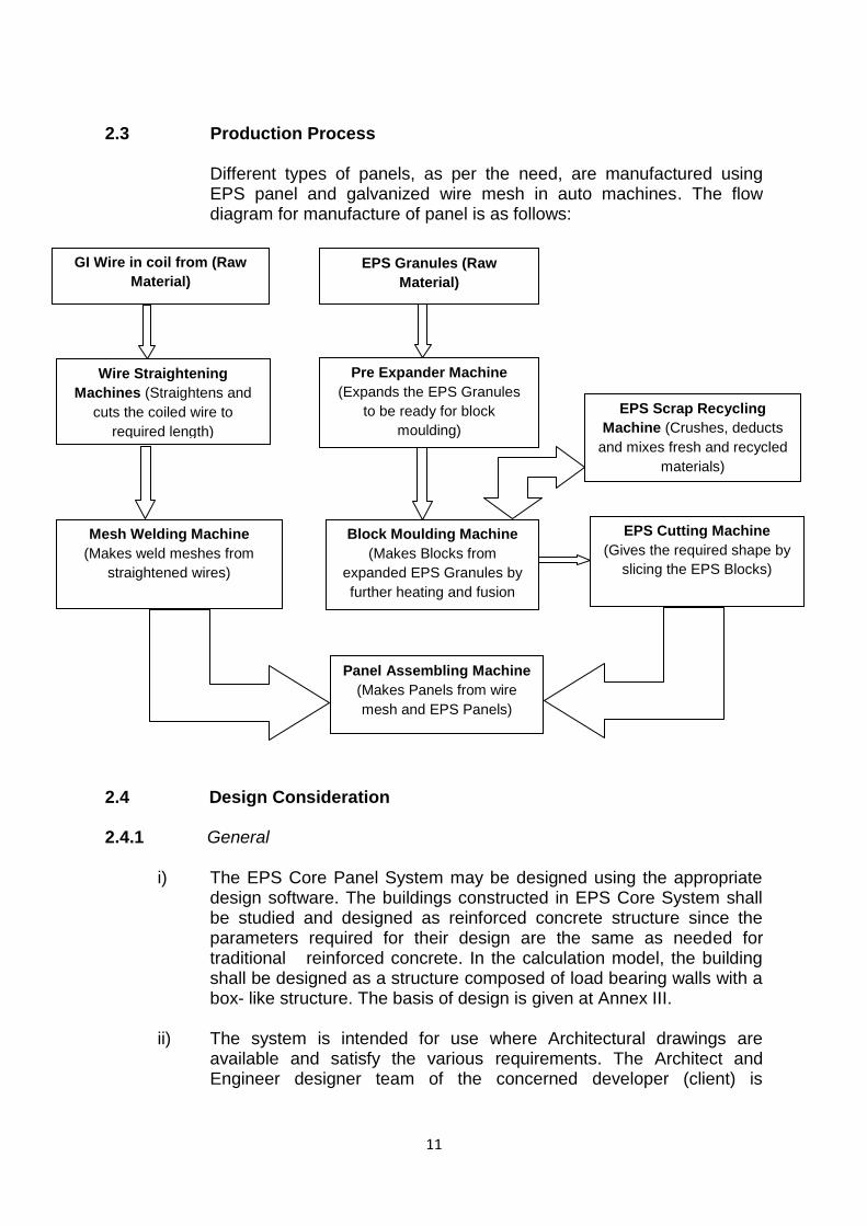
2.3 Production Process
Different types of panels, as per the need, are manufactured using EPS panel and galvanized wire mesh in auto machines. The flow diagram for manufacture of panel is as follows:
2.4 Design Consideration 2.4.1 General
i) The EPS Core Panel System may be designed using the appropriate design software. The buildings constructed in EPS Core System shall be studied and designed as reinforced concrete structure since the parameters required for their design are the same as needed for traditional reinforced concrete. In the calculation model, the building shall be designed as a structure composed of load bearing walls with a box- like structure. The basis of design is given at Annex III.
ii) The system is intended for use where Architectural drawings are available and satisfy the various requirements. The Architect and Engineer designer team of the concerned developer (client) is
GI Wire in coil from (Raw
Material)
EPS Granules (Raw
Material)
Wire Straightening
Machines (Straightens and
cuts the coiled wire to
required length)
Pre Expander Machine
(Expands the EPS Granules
to be ready for block
moulding)
EPS Scrap Recycling
Machine (Crushes, deducts
and mixes fresh and recycled
materials)
Mesh Welding Machine
(Makes weld meshes from
straightened wires)
Block Moulding Machine
(Makes Blocks from
expanded EPS Granules by
further heating and fusion
EPS Cutting Machine
(Gives the required shape by
slicing the EPS Blocks)
Panel Assembling Machine
(Makes Panels from wire
mesh and EPS Panels)

12
responsible for the drawings and overall building design to comply with the various regulatory requirements applicable to the area.
iii) The Engineer of JSPL shall liaise with the engineer of the developer
and provide the necessary loading information for the design of the foundation.
iv) The system shall be designed to provide the required performance
against the loads to be taken into account in accordance with IS 875 (Parts 1-5):1987 and the data given by manufacturer for various panels. It shall also provide the required bearing resistance for earthquake and wind forces as per IS 875 (Part 3):1987 and IS 1893 (Part 1):2002, wherever applicable.
v) Foundation shall be specifically designed in accordance with provision
given in IS 1904:1986. The design concept is same as that of the conventional building design. The safe bearing capacity and soil properties (soil investigation report)) shall be provided from the site after soil investigations. Foundation shall be designed based on the soil investigation report. Both single and double panels should have starter bars from either foundation or ground floor slab. All foundations should be designed by experienced engineer with appropriate reference.
vi) The design assumptions, detailed calculations, references to
necessary and detailed design drawings shall be made available on demand, if required. The structural design calculations should clearly demonstrate structural integrity and stability including connection details. Design calculations should have proper sketches annotated in English.
vii) In addition, any other requirement regarding safety against earthquake
need to be ensured by the designer as per prevailing codal requirements.
2.4.2 Structure
The EPS Core Panel System receives its outer plane strength and
rigidity by truss action where the shotcrete layers are the chord
members. Design guidelines and requirements set out in the Technical
literature provided by the manufacturer shall be followed.
2.4.3 Wind Uplift
The design of roof to wall connections shall be to a specific design to
ensure that the roof structure is properly restrained against uplift.
2.4.4 In-fill Wall
When used as in-fill wall in framed RCC structure, the frame structure shall be designed in accordance with IS 456:2000 or IS 800: 2007 as

13
applicable. The fixing of the panels shall be done in accordance with the details provided by the certificate holder.
2.5 Installation Procedure 2.5.1 Foundations
Foundations for the EPS Core Panel system whether strip or raft are conventional. If strip foundations are used, they should be level and stepped as this makes panel positioning easier. For EPS Core panels, parallel sided timber or metal template of the width of panel shall be required to mark the position of the wall panels on the foundation and the spacing of the starter bar holes.
2.5.2 Wall start up
Line wall positions shall be marked and profiled. A timber or metal template of the exact width of panel (from wire to
wire) shall be used to mark the position of the panels with chalk or pencil lines.
On the panel lines positions shall be marked to drill the starter bar holes. These should be in a zig zag pattern at 600mm centres on each side of the panels. Starter bars should be at all panel joints and on the opposite side in mid panel plus at all wall corners and joints.
Starter bars should be either 6mm or 8mm dia. 500mm long with 100mm drilled into the foundations and 400mm above.
Drill bits shall be used to give a tight fit with the starter bars. Once starter bars are in position, place the EPS Core panels
between the starter bars starting from a corner. Starter bars shall be wire-tied to the panel mesh and the panels to each other on the overlapping mesh.
2.5.3 Wall construction
All corners and wall joints shall be reinforced with right angled wire mesh to the full height of the walls.
To cut panels to fit for door & window openings, wire should be cut with a wire cutter or angle grinder. Measure and mark the cut lines before starting to cut.
After the wire mesh has been cut, EPS shall be cut with a hacksaw blade or stiff blade hand saw.
Added steel mesh reinforcement shall be required around door and window openings to ensure that no plaster cracks form in these areas. Mesh reinforcement strips shall be tied diagonally with wire around openings before plastering.
Once wall panels are in place and tied together, bracing shall be required to hold them vertical before plastering. This shall be done only on one side of the panels.
14
Once the panels are plastered on one side, the wall bracing shall be removed after 24 hours. Plastering on other side can be done without bracing.
2.5.4 Door and Window fittings
2.5.4.1 First method
Fix a metal angle iron or hollow tube sub frame into the openings before plastering. Fix and plaster these in place and then secure the frames to the sub frame.
In order to secure heavy door/window frames, the EPS where the bolts are to be fixed to the wall shall be burnt or cut and this space shall be filled with mortar or concrete to hold the bolts.
2.5.4.2 Second method
Before plastering metal ‘cliscoe’ type window and door frames (which should be sized to the width of the panels) may be fitted into the pre-cut panels.
Metal ‘cliscoe’ type window frame fitted into future house panel before plastering.
Metal lugs from the back of metal frames shall be wire tied to the panel mesh to keep the frames in position.
2.5.5 Roof/floor panel
After the vertical panels are assembled, verticality of the walls shall
be checked and the bending meshes positioned on all the corners. Thereafter, horizontal bending meshes shall be placed to connect the floor/roof to the vertical panels. The bending meshes shall be fixed throughout the perimeter of the floor/roof, at the level of intrados.
When the horizontal bending meshes are fixed and checked, floor/roof panel shall be placed on these. The lower mesh of the panel shall be fixed by steel wire to the bending meshes.
Between the edges of floor/roof panel and vertical panel, gap of 35 mm should be left to ensure structural continuity. The plaster applied on the walls shall be continued from one level to another level.
Placing of the EPS Core Panel elements for the floor and/or roof should be done before the application of the external layer of plaster on the walls. Casting of concrete on the floor/roof panels (after placing the additional reinforcing bars, if required) should be done after the walls are plastered and a number of props shall be put to limit the deformation of the panel.
15
2.5.6 Plastering
Plastering shall be done by machine or hand. The indicative quantity of each material per cum. should conform to relevant Indian Standards and shall be: (i) Cement: 350kg (ii) Sand with mixed granulometry: 1600kg. Sand should be
without clay or any organic substance and totally washed. (iii) Water – 160litres. The quantity of water may be different
according to the natural sand humidity. The parameters that should be constant are: W/C = 0.52 and I/C = 4.50.
Any problem of workability should be solved without adding water. The retraction cracks formation may be avoided by adding polypropylene fibers in the mix (1kg/m3).
In order to control the final plaster thickness, some guides should be used. These shall be removed as soon as the plaster ‘sets up’ and the spaces are filled and are smoother before the plaster gets dry.
Spray application should be done in two steps with a first layer covering the mesh applied on both the sides of the wall and the finishing layer as soon as the first layer gets dry.
2.5.7 Plumbing and electrical fittings
Plumbing and electrical conduits shall be behind the panel wire
mesh before plastering. The space behind the wire mesh shall be opened up by using a
blow torch to partially melt the EPS along the lines of the conduits. As the EPS used in the panels is fire retardant, it will melt under
the flame but not burn. The wire mesh shall be cut with wire clippers to make space for DB
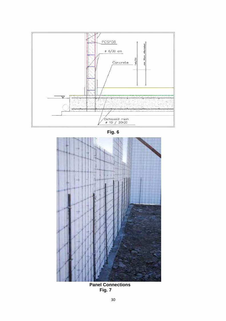
boards, switches and plug boxes. 2.5.8 Connection
The Reinforced EPS Wall system is composed by panels consisting of a polystyrene sheet assembled together with welded wire mesh. Various connections are detailed in Figs 5 to 35 of Annexure II which may be referred.
2.6 Machinery Involved
i. Electronic Polystyrene cutting machine ii. Wire straightening machine iii. Automatic welding mesh machine iv. Automatic welding and Panel assembling machine v. Automatic mesh cutting machine vi. Automatic mesh binding machine
16
2.7 Tools required
i) Parallel side timber of metal template to mark the portion of the
wall panel on the foundation and the spacing. ii) Electric drill and extension cord with connect drill bits (6 or 8m)
for drilling holes for the starter bar. iii) Tape to measure, dimension. iv) Pliers for wire tying v) Level and or plumb lines to ensure panels are plumb are plumb
and straight. vi) Heavy duty wire cutters. vii) Hand hold blow torch. viii) Normal plaster tools.
2.8 Inspections & Testing
Inspections & testing shall be done at appropriate stages of manufacturing process. The inspected panels shall be stored & packed to ensure that no damage occurs during transportation. As part of quality assurance, regular in-process inspections shall be carried out by the trained personnel of the PAC holder.
2.9 Handling, Storage and Marking & Identification
i) The panels should be stored on a clean, flat hard surface area on the site. The panels should not be laid down directly on the ground to prevent them from getting dirty, which could lead to problems of plaster adhesion. Preferably, panels should be stored on timber battens approx 2m apart.
ii) The panels should not be exposed to sunlight for not more than 1 month either in storage or during construction in order to prevent changing the polystyrene appearance. The panels should be bound carefully to make sure these are not accidentally blown by the wind.
iii) Long term storage of the panels shall be done in a covered, protected, dry environment so that corrosion of the reinforcement does not occur and the panels do not get damaged.
iv) Panels shall be stored and transported to site in a manner that prevents damage, buckling or sprawling of the polystyrene or bending of the mesh reinforcement. Operatives should place the panels in position and tie them down to starter bars of adjoining panels and slabs in the manner described in the Operational Manual.
v) Panels should be properly braced to provide rigid temporary support to the walls during erection and concrete spraying and placing of concrete in slabs. Propping of walls and slabs should be in accordance with Operational Manual.
vi) The panels shall be delivered to the site with an identification issued by the manufacturer that reports the element height.
17
vii) The panel layout shall provide instructions for laying the components correctly.
2.10 Good Practices for Installation & Maintenance
Good practices as per requirement of working with EPS Core Panel System of the certificate holder shall be followed for installation of these panels.
2.11 Maintenance Requirements A proper maintenance guide shall be given by the PAC holder to the client. When building is to be repainted with fresh coat of paint after scraping existing paint, check for joint sealant, pipe joint, sun shade etc. and carry out required maintenance and apply primer before paint is applied.
2.12 Skilled /Training Needed for Installation
Workers shall be trained/ oriented on handling of panel and its erection, support system, clamping system, infilling of reinforcement and concrete etc. with all required safety measures taken including heavy hats, protective shoes etc.
2.13 Health & Safety Measures
Apart from Construction Guidelines, Manufacturers Catalogues, recommendations and other technical literatures should also be consulted. Following additional construction guidelines should also be followed. Always follow applicable Occupational Safety and Health
Administration (OSHA) guidelines and safety requirements. Work gloves (especially this globes) are highly recommended to
protect hands from cuts and injuries when working with steel. 2.14 Guarantees/Warranties Provided by the PAC Holder
PAC holder shall provide necessary guarantees/ warranties. A brochure giving relevant details of the EPS Core Panel System shall be made available to the client.
2.15 Services Provided by the PAC Holder to the Customer
In-house testing of panels at regular intervals as per the Quality Control Assurance requirement shall be ensured by PAC Holder.
2.16 Manuals
A site Erection Manual and a Manual for Health & Safety shall be provided for each project incorporating the EPS Core Panel System.

18
2.17 Responsibility
Specific design using EPS Core Panel System is the responsibility of the designer with the instructions, supervision and guidance of Schnell Wire System.
Quality of installation of the system on site is the responsibility of the trade persons engaged by the agency
Quality of maintenance of the building is the responsibility of the building owner.
Providing necessary facilities and space for movement of cranes and vehicles is the responsibility of the building developer.
PART 3 BASIS OF ASSESSMENT AND BRIEF DESCRIPTION OF ASSESSMENT PROCEDURE
3.1 Assessment 3.1.1 Factory Inspection 3.1.2 The assessment of the system is based on the panels manufactured,
used, installed and maintained as per statement given in the PAC. 3.2 Laboratory tests performed for assessment 3.2.1 Testing of samples by Foreign Laboratories/ Institutes
The following tests have been performed by various foreign institutes as per the specifications given by the manufacturer: 1. By Giordano Institute, Italy -- Thermal Insulation Tests:
Single Panel - Thermal transmittance Up = 0.58 W/m2K
2. By CSI (MI), Italy – Acoustic Tests ● Single Panel - Traditional plaster Rw= 37 dB ● Single Panel – acoustic plaster Rw= 37dB 3. By LAPI (PO) – Water Penetration Test
● Single Panel- No Penetration was observed after three hours.
3.2.1.1 By Wind Science & Engineering Research Center, Texas Tech
University
Missile Test was conducted by Wind Science & Engineering Research Center, Texas Tech University on 130 mm and 150 mm thick panels: Missile test according to Florida Building Code, International Code Council, Texas; Deptt. of Insurance Windstorm Resistance Construction Guide. The following results were obtained:

19
1. PCSP08 panels – are resistant to the Florida Building Code & Dade County Hurricane Envelope resistance = 55 km/h missile & 225 km/h hurricane.
2. PCSP08 panel – threshold of perforation = 142 km/h missile & 354 km/h hurricane impact resistance. Since two of the panels were tested to the highest standard for hurricanes 177 km/h & 355 km/h hurricane and were reasonably resistant, the 150 mm panel can be rated to 146 km/h & 362 km/h hurricane impact resistance, which is the highest rating per ICC-5r00 Standard.
3.2.1.2 Evaluation Report of the Characterization Tests carried out by
Department of Architecture, Buildings & Structures, University Polytechnic of Marche.
The following tests were carried out forming part of this report: 1. Characterization tests on materials
1.1 Tests on the electro-welded mesh: The electro-welded mesh
was put through pulling tests. Two of the six tested samples had a fragile behaviour by the joint welding before yielding while the other four reached the yield point but showed very low ductility 9 (Lower than 2). The maximum strength was always found higher limit given in EN ISO 15630-2:2004. The minimum strength to detachment is 25% of the yield strength.
1.2 Tests on the core layer: In order to know the mechanical
features of the panel core layer, creep tests were performed on samples made of three layers of sprayed structural plaster and two connecting layers. The tests were repeated on identical samples but without the polystyrene inner layers. The test with double joints gave on average value of G=3.2N/mm2.
2. Bending test on floor panels: Six tests were carried out on the
following panels:
- Two tests on PCSS 08 panels (single panel – 80 m thick) (total thickness 16 cm) with a 3.3 m clear span;
- Two tests on PCSS 12 panels (single panel floor – 80 m
thick) (total thickness 20 cm) with a 4.3 m clear span; - Two tests on PCSS 16 panels (single panel floor– 80 m
thick) (total thickness 24 cm) with a 5.3 m clear span;
3. Compression tests on wall panels: A total of 16 tests were carried out as detailed below:

20
- Two centred compression tests on PCSP08 panels (2a 1, 2a 2)
- Two centred compression tests on PCSP12 panels (3a 1, 3a 2) - Two eccentric compression test on PCSP16 panels (4a 1, 4a 2) - One centred compression test on PCSE08 panel (X2) - One centred compression test on PCST08 panel (Y2) - Two eccentric compression tests on PCSP08 panels (2b 1, 2b) - Two eccentric compression tests on PCSP12 panels (3b 1, 3b 2) - Two eccentric compression tests on PCSP16 panels (4b 1, 4b 2) - One eccentric compression test on PCSE08 panel (X1) - One eccentric compression test on PCSE08 panel (Y1)
The alternate loads per unit of length were observed very high so the stability out of the plane seem not to be approvable for any of the test panel.
4. Diagonal Compression tests on wall panels: The following tests
were carried out: - Two diagonal compression tests on single panels (panels
5.1 & 5.2) - Two diagonal compression tests on transversely pre-
stressed single panels (panels 5.3 & 5.4) - Two diagonal compression tests on single panels
stiffened along their perimeter (panels C.1 & C.2)
5. Tests on wall-floor joints: Each sample is formed by PSCP08 wall panels and PCSS08 floor panels. The following tests were carried out: - One test on a joint where the floor panel upper face was
tied to the wall panel outer face (joint 1) - One test on a joint where the floor panel faces were tied
to the wall panel inner face (joint 2)
6. Static test on a floor built with wall panels: The floor under testing was made of single floor panel and the prototype vertical walls made of single bearing panels PCSP08.
The static test was carried out progressively until the floor collapsed with a nominal load uniformly distributed acting on the loaded floor portion of 2000 kgf/m2.
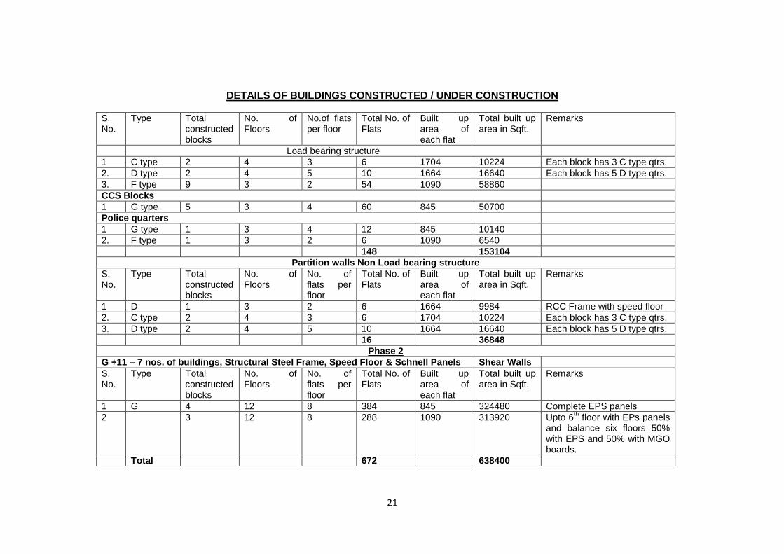
3.3 Usage of the System
A list of projects completed is given below.
21
DETAILS OF BUILDINGS CONSTRUCTED / UNDER CONSTRUCTION
S. No.
Type Total constructed blocks
No. of Floors
No.of flats per floor
Total No. of Flats
Built up area of each flat
Total built up area in Sqft.
Remarks
Load bearing structure
1 C type 2 4 3 6 1704 10224 Each block has 3 C type qtrs.
2. D type 2 4 5 10 1664 16640 Each block has 5 D type qtrs.
3. F type 9 3 2 54 1090 58860
CCS Blocks
1 G type 5 3 4 60 845 50700
Police quarters
1 G type 1 3 4 12 845 10140
2. F type 1 3 2 6 1090 6540
148 153104
Partition walls Non Load bearing structure
S. No.
Type Total constructed blocks
No. of Floors
No. of flats per floor
Total No. of Flats
Built up area of each flat
Total built up area in Sqft.
Remarks
1 D 1 3 2 6 1664 9984 RCC Frame with speed floor
2. C type 2 4 3 6 1704 10224 Each block has 3 C type qtrs.
3. D type 2 4 5 10 1664 16640 Each block has 5 D type qtrs.
16 36848
Phase 2
G +11 – 7 nos. of buildings, Structural Steel Frame, Speed Floor & Schnell Panels Shear Walls
S. No.
Type Total constructed blocks
No. of Floors
No. of flats per floor
Total No. of Flats
Built up area of each flat
Total built up area in Sqft.
Remarks
1 G 4 12 8 384 845 324480 Complete EPS panels
2 3 12 8 288 1090 313920 Upto 6th floor with EPs panels
and balance six floors 50% with EPS and 50% with MGO boards.
Total 672 638400

22
PART 4 STANDARD CONDITIONS
This certificate holder shall satisfy the following conditions: 4.1 The certificate holder shall continue to have the product reviewed by BMBA. 4.2 The product shall be continued to be manufactured according to and in
compliance with the manufacturing specifications and quality assurance measures which applied at the time of issue or revalidation of this certificate. The Scheme of Quality Assurance separately approved shall be followed.
4.3 The quality of the product shall be maintained by the certificate holder. Complete
testing facilities shall be installed for in-process control. 4.4 The product user should install, use and maintain the product in accordance with the
provisions in this Certificate. 4.5 This certificate does not cover uses of the product outside the scope of this appraisal. 4.6 The product is appraised against performance provisions contained in the certificate
and relevant standards listed in Part-V. Provisions of any subsequent revisions or provisions introduced after the date of the certificate do not apply.
4.7 Where reference is made in this Certificate to any Act of Parliament of India, Rules
and Regulations made there under, statutes, specifications, codes of practice, standards etc. of the Bureau of Indian Standards or any other national standards body and the International Organization for Standardization (ISO), manufacturer’s company standards, instruction/manual etc., it shall be construed as reference to such publications in the form in which they were in force on the date of grant of this Certificate (and indicated in Part V to this Certificate)
4.8 The certificate holder agrees to inform BMBA of their clients with details of
construction on six monthly basis. 4.9 The certificate holder agrees to provide to BMBA feedback on the complaints
received, the redressal provided, and the time taken to provide redressal on complaint to complaint basis as soon as redressal is provided. BMBA agrees to provide the certificate holder the user feedback received by it, if any.
4.10 If at any time during the validity period, PACH is unable to fulfil the conditions in his
PAC, he should on his own initiative suspend using the PAC and notify Chairman, TAC the date from which he has suspended its use, the reason for suspension and the period by which he will be able to resume. He shall not resume without the prior permission of BMBA. He shall also inform, simultaneously, his agents, licensees, distributors, institutional, government, public sector buyers, other buyers and all those whom he has informed about his holding the PAC. He shall also inform all those who buy his product(s) during the period of suspension. He shall provide to BMBA at the earliest the list of who have been so informed by him.

24
PART 5 LIST OF STANDARDS & CODES USED IN ASSESSMENT
5.1 Standards - These Standards are referred for design / carrying out particular tests only and do not specify the requirement for the whole product as such. 5.1.1 IS 456:2000 -- Code of practice for plain and reinforced concrete 5.1.2 IS 875 (Part 1):1987 -- Code of Practice For Design Loads (Other Than Earthquake) for Buildings And Structures Part 1 Dead Loads - Unit Weights of Building Material And Stored Materials (Incorporating IS 1911 : 1967) 5.1.3 IS 875 (Part 2):1987 -- Imposed Loads 5.1.4 IS 875 (Part 3):1987 -- Wind Loads 5.1.5 IS 875 (Part 4):1987 -- Snow Loads 5.1.5 IS 875(Part 5):1987 -- Special Loads And Combinations. 5.1.6 IS 1893(Part 1):2002 -- Criteria for Earthquake Resistant Design of Structures 5.1.7 IS 4671:1984 -- Specifications for expanded polystyrene for thermal insulation purposes 5.1.8 IS 4326:1993 -- Code of Practice for Earthquake Resistant Design and Construction of Buildings 5.1.9 EN13501-2:2007/ BS 476(Part 22):198 -- Fire resistance 5.1.10 ASTM E 1886-04 -- Standard Test Method for Performance of Curtain walls, Doors, Windows and Impact protection systems impacted by Missiles & exposed to cyclic pressure differentials 5.1.11 ASTM E90-90 -- Sound Proofing 5.1.12 UNI EN ISO 10211(Part 1& 2):1996 -- Thermal insulation 5.1.13 UNI EN ISO 140(Part 3):2006 -- Acoustic Insulation 5.1.14 MIP 058:2008 -- Test method for Impact with a soft body and Impermeability to water jet 5.1.15 FEMA 320/361/The ICC 500 -- Standard for the Design & construction of Storm shelters (Debris impact).
Part 5.2 Company Standards of the PAC holder – The branded design & specifications of the raw materials and finished product are as submitted by the manufacturer. The PAC holder has to make available the company standards to the consumers according to which testing have been done.

26
PART 6 ABBREVIATIONS
Abbreviations BMBA Board of Agreement of BMTPC BMTPC Building Materials and Technology Promotion Council CPWD Central Public Works Department ED Executive Director of BMTPC IO Inspecting Officer MS Member Secretary of BBA PAC Performance Appraisal Certificate PACH PAC Holder PACS Performance Appraisal Certification Scheme SQA Scheme of Quality Assurance TAC Technical Assessment Committee (of BMBA)

27
Performance Appraisal Certification Scheme - A Brief
Building Materials & Technology Promotion Council (BMTPC) was set up by the
Government of India as a body under the Ministry of Housing &Urban Poverty
Alleviation to serve as an apex body to provide inter-disciplinary platform to promote
development and use of innovative building materials and technologies laying
special emphasis on sustainable growth, environmental friendliness and protection,
use of industrial, agricultural, mining and mineral wastes, cost saving, energy saving
etc. without diminishing needs of safety, durability and comfort to the occupants of
buildings using newly developed materials and technologies.
During the years government, public and private sector organizations independently
or under the aegis of BMTPC have developed several new materials and
technologies. With liberalization of the economy several such materials and
technologies are being imported.
However, benefits of such developments have not been realized in full measure as
understandably the ultimate users are reluctant to put them to full use for want of
information and data to enable them to make informed choice.
In order to help the user in this regard and derive the envisaged social and economic
benefits the Ministry of Housing &Urban Poverty Alleviation has instituted a scheme
called Performance Appraisal Certification Scheme (PACS) under which a
Performance Appraisal Certificate (PAC) is issued covering new materials and
technologies. PAC provides after due investigation, tests and assessments, amongst
other things information to the user to make informed choice.
To make the PACS transparent and authentic it is administered through a Technical
Assessment Committee
(TAC) and the BMTPC Board of Agreement (BMBA) in which scientific,
technological, academic, professional organizations and industry interests are
represented.
The Government of India has vested the authority for the operation of the Scheme
with BMTPC through Gazette Notification No. 1-16011/5/99 H-II in the Gazette of
India No. 49 dated 4th December, 1999.
Builders and construction agencies in the Government, public and private sectors
can help serve the economic, development and environmental causes for which the
people and Government stand committed by giving preference to materials and
technologies which have earned Performance Appraisal Certificates.
Further information on PACS can be obtained from the website: www.bmtpc.org.

28
ANNEX I (Clause 1.6.2) QUALITY ASSURANCE PLAN FOR REINFORCED EPS CORE PANEL SYSTEM
Sl.No. Process/operation Quantum of Check Reference/Aceptance Norms Instruments Used Type of Record PROD-JSPL QA-JSPL
1 Raw Materials
100 % dimensions AS per IS 280-1978 Vernier Calliper MTC Review Review
100 % mechanical properties AS per IS 280-1978 MTC Review Review
100 % chemical properties AS per IS 280-1978 MTC Review Review
1.2 EPS Granules 100 % chemical properties MTC Review Review
2 Process
Random density check +/- 5 % of required density - minimum 15 Kg/CUM Weighing Scale Production Record Record Review
Random visual check Should be free from visual cracks Production Record Review Review
Random visual check Should be of uniform sizes Production Record Review Review
2.2 EPS Blocks 100 % density check +/-5 % of required density - minimum 15 Kg/CUM Weighing Scale Production Record Record Review
100 % bonding strength check blocks must exhibit strong cohesion among beads Production Record Review Review
100 % visual check Surface should be smooth,free from cracks and distortion Production Record Review Review
100 % ID Marking DOM,Weight,Density,Time and Block No. Marked on the block Marker Production Record Perform Record
2.3
2.4 GI Wire mesh Random Dimensions Check +/- 1 % deviation from specified pitch Vernier Calliper Production Record Review Review
Random Weld strength check Should with stand pull load of 45 kgf UTM/Manual load test Perform Record
2.5 EPS Panels 100 % Visual check All vertical connections joined to the cross wires Review Review
100 % Dimensions check All Dimensions are within 0.5 % tolerance range Tape Measure Production Record Review Record
2.6 Packing 100 % Visual check As mentioned/Requirement of PO. Review Review
2.7 Despatch 100 % Visual check As per PO terms and conditions Packing List Review Record
1.1 Zinc coated Wire
2.1EPS Pre expanded
beads

29
ANNEX II (Clause 2.5.8) DRAWINGS Connections There are several techniques available for connecting EPS Wall components; The EPS wall system is composed by panels consisting of a polystyrene sheet
assembled together with welded wire mesh. The panels are finished on site by
spraying concrete to realise the different elements of the system:
- Vertical structural walls; - Horizontal structural elements; - Cladding elements; - Internal walls.
Foundation Anchor Fig. 5
30
Fig. 6
Panel Connections Fig. 7
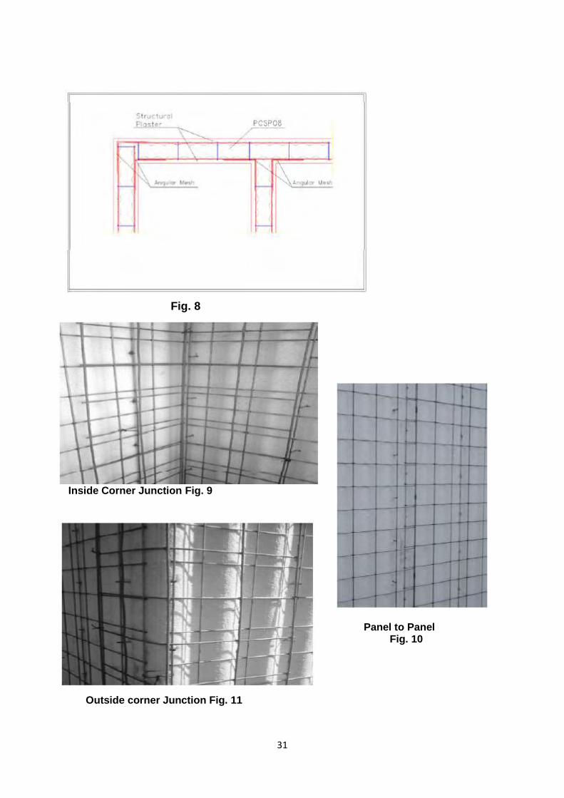
31
Fig. 8
Inside Corner Junction Fig. 9
Panel to Panel Fig. 10
Outside corner Junction Fig. 11

32
Fig. 12
Fig.13

33
Fig. 14
Fig. 15
34
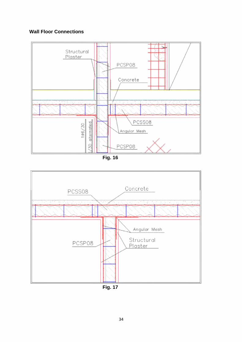
Wall Floor Connections
Fig. 16
Fig. 17
35
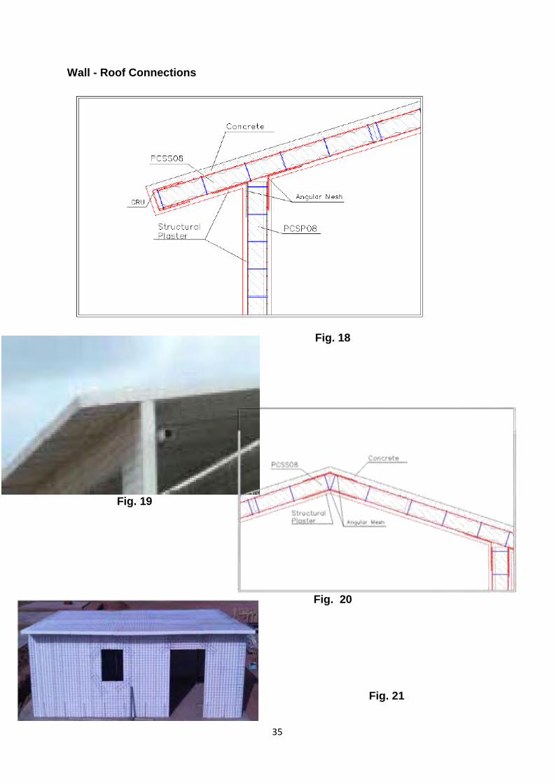
Wall - Roof Connections
Fig. 18
Fig. 19
Fig. 20
Fig. 21
36
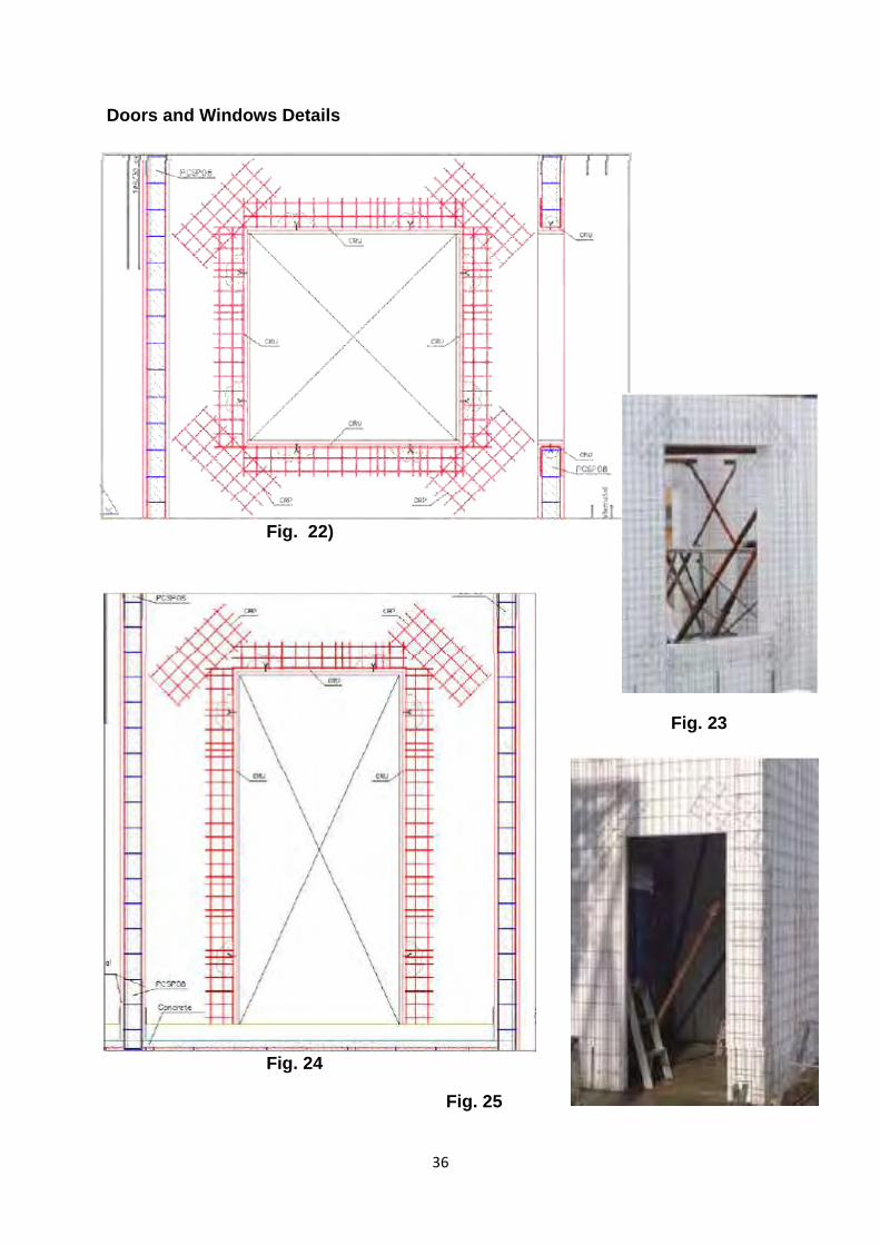
Doors and Windows Details
Fig. 22)
Fig. 23
Fig. 24
Fig. 25

37
Seismic Joint Detail
Fig. 26
Anchorage Detail on Single Panel:
Fig. 27

38
Connection Single Panel with Floor Panel:
Fig. 28
Fig. 29

39
Connection Single Panel with Floor Panel
Fig. 30
Fig. 31

40
Connection Single Panel with Floor Panel
Fig. 32
Fig. 33

41
Fig. 34
Fig. 35

42
ANNEX III (Clause 2.4.2) 1. DESIGN PHILOSOPHY 1.1 Design Basis Design of EPS Panels is based on the below mentioned standards, codes and engineering practices IS 875-1:1987 Code of Practice for Design Load (Other than Earthquake) for
Building and Structures-Part 1-Dead Loads Unit of Building Materials and Stored Materials.
IS 875-2:1987 Code of Practice for Design Load (Other than Earthquake) for Building and Structures-Part 2-Imposed Loads.
IS 875-3:1987 Code of Practice for Design Load (Other than Earthquake) for Building and Structures-Part 3-Wind Loads.
IS 1893-1: 2002 Criteria for Earthquake Resistance Design of Structures- Part 1 General Provision and Buildings
BS13163: 2001 Thermal Insulation Products for Buildings – Factory made products of expanded polystyrene (EPS) – Specification.
IS 9012: 1978 Recommended Practices for shotcreting. 1.2 Load Calculations 1.2.1 Dead Load
Dead load has to be calculated based on the unit weight provided in IS 875 Part-1 1987 for each work. Even though total Weight of wall highly depends on the type of finish material/ Shot Crete/ other finishes. Normally it varies from 0.45 Kn/m2 to 1.2 Kn/m2
Weight of the floor normally varies from 2.5 Kn/m2 to 3 Kn/m2
Load for Roof normally varies from 0.4 Kn/m2 to 0.75 Kn/m2 for GI Sheet and 2.4Kn/m2 to 3 Kn/m2 for R.C.C Slab
These are indicative values.
1.2.2 Live Load
Live load for different occupancies may be taken from IS 875 Part-2 1987; Table 1
Live load for dwelling units is considered 2.0 Kn/M2 Except corridors and balconies (3.0 Kn/M2).
Entire load of 0.5 Kn/M2 shall be considered for service and false sealing

43
1.2.3 Wind Load
Wind loads apply on face of elevations of the buildings. The face loads are transferred from the cladding outer leaf by the wall ties to the stud sections which span vertically between horizontal floor diaphragms. The floor diaphragm spans horizontally between each of cross walls which can be internal load bearing or external walls.
1.2.3.1Wind load analysis
Wind load analysis conduct as per IS875-Part3. The 90 degree case acts on the side elevation and 0 degree wind load case acts on the front or back elevation. Each elevation will be analysed separately and the highest calculated load will be applied throughout the entire structure. Therefore, this technique is deemed to be conservative.
Overturning (global stability) and holding down analysis is conducted for the widest cases. Comprehensive explanation of the global stability analysis follows.
Design wind pressure (N/m^2) Pz = 0.6 x Vz2
(IS875-1987 Part-3; Clause:5.4 Page:12)
Design wind speed (m/s) Vz = VbxK1xK2xK3 (IS875-1987 Part-3; Clause:5.3 Page:8)
Basic wind speed (m/s) Vb (IS 875(part 3)-1987; Fig 1 Page:9)
Risk coefficient factor (K1) (IS 875(part 3)-1987:Table:1Clause:5.3.1 Page:11)
Terrain, height and Structure factor (K2) IS 875(part 3)-1987; Table 2 ; Clause:5.3.2 (Page:12)
Topographic factor (K3) (IS 875(part 3)-1987; Clause 5.3.3.1; Page:12)

44
1.2.4 Seismic Load
Seismic loads apply on the each floor and roof level of the buildings. The horizontal loads are transferred from the floor Panel to the walls tying or supporting the floors and roof.
By inspection, the seismic loads are critical for overall stability.
Total Design lateral Force or Seismic Base Shear V (kN) = Ah x W total
(As per IS1893-2002 (Page24); Cl 7.5.3)
Design Horizontal Seismic Coefficient Ah= (ZISa/2Rg) (As per IS1893-2002(page: 14) Clause: 6.4.2)
Zone Factor (Z) (As per Table2 IS1893-2002(page: 16) Clause: 6.4.2)
Seismic Zone (As per Seismic Zone map IS1893-2002) (page: 5)
Seismic Intensity (As per Table2 IS1893-2002(page: 16) Clause: 6.4.2)
Importance Factor (I) (As per Table6 IS1893-2002(page: 18) Clause:6.4.2)
Response Reduction Factor (R)
(As per Table7 IS1893-2002(page: 23) Clause:6.4.2)
Average response acceleration coefficient factor (Sa/g) (As per IS1893-2002(page: 16) Clause:6.4.5)
Total weight of building (W, total) (kN) (As per IS1893-2002 (Page17); Clause 7.3)
1.2.5 Serviceability Requirements
Serviceability performance concerns the limits on deflections due to loading and the control of vibrations, due to regular activities. Appropriate limits are specified, depending on the application
1.2.5.1Deflection
The deflection under serviceability loads of a building or its members should not impair the strength or efficiency of the structure or its components or cause damage to the finishing. The recommended deflection limits for certain structural members shall be as per IS 456:2000 and IS 1893:2000
Fig. 36

45
Table : Deflection
a) Deflection of beams due to factored imposed loads
Cantilever Length/180
Beams carrying plaster or other brittle finish
Span/360
All other beams Span/200
B deflection of columns other than portal frames due to unfactored imposed and wind loads
Tops of columns in single-storey buildings
Height/300
In each storey of a building with more than one storey
Height of storey under consideration/300
Deflection criteria
Static criteria
a) The maximum deflection for a single panel subject to dead and imposed loads is limited to the smaller of span/350 , or 15 mm
b) The maximum deflection for a single Panel subject only to imposed load is limited to span/450
Dynamic criteria
a) The natural frequency of the floor should be limited to 8 Hz for the uniformly distributed load case of dead plus 0.3 kn/m2, which represents the nominal load on lightly loaded floor. This is achieved by limiting the deflection of a single Panel to 5mm for this loading condition.
b) For the floor subjected to imposed loads in excess of 1.5 Kn/m2, the governing criterion is most likely to be (a) (Span/350 or a maximum of 15mm)
Deflection of uniformly distributed simply supported beam can calculate by
(
)
E is the modules of Elasticity 205000 N/mm2 I is the moment of inertia mm4 W is the total uniform load l Span length.
1.2.6 Robustness of EPS panels (Applicable to 5 floors and above)
The Building Regulations require that structures of 5 or more storeys should be designed to localize the effects of accidental damage. There is currently no published guidance on the ‘robustness’ of EPS Panels to accidental effects, within the context of the Building Regulations.
46
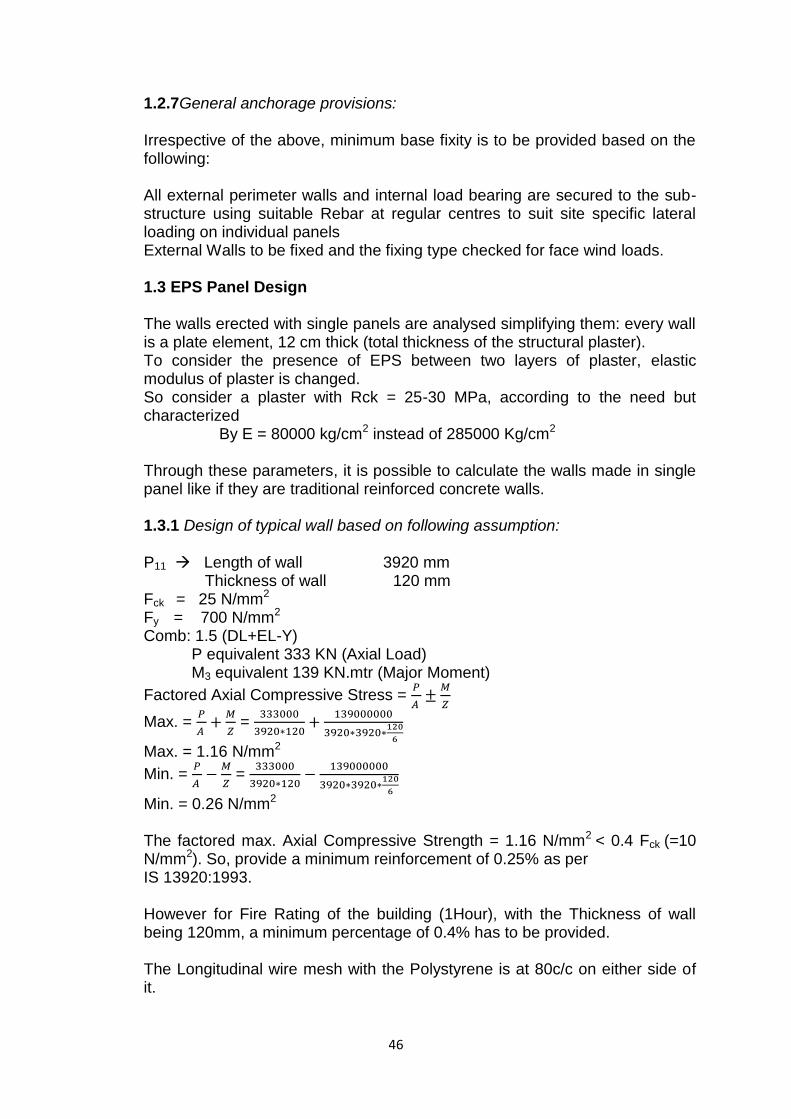
1.2.7General anchorage provisions:
Irrespective of the above, minimum base fixity is to be provided based on the following:
All external perimeter walls and internal load bearing are secured to the sub-structure using suitable Rebar at regular centres to suit site specific lateral loading on individual panels External Walls to be fixed and the fixing type checked for face wind loads.
1.3 EPS Panel Design The walls erected with single panels are analysed simplifying them: every wall is a plate element, 12 cm thick (total thickness of the structural plaster). To consider the presence of EPS between two layers of plaster, elastic modulus of plaster is changed. So consider a plaster with Rck = 25-30 MPa, according to the need but characterized By E = 80000 kg/cm2 instead of 285000 Kg/cm2
Through these parameters, it is possible to calculate the walls made in single panel like if they are traditional reinforced concrete walls.
1.3.1 Design of typical wall based on following assumption:
P11 Length of wall 3920 mm
Thickness of wall 120 mm Fck = 25 N/mm2
Fy = 700 N/mm2
Comb: 1.5 (DL+EL-Y) P equivalent 333 KN (Axial Load) M3 equivalent 139 KN.mtr (Major Moment)
Factored Axial Compressive Stress =
Max. =
=
Max. = 1.16 N/mm2
Min. =
=
Min. = 0.26 N/mm2
The factored max. Axial Compressive Strength = 1.16 N/mm2 < 0.4 Fck (=10 N/mm2). So, provide a minimum reinforcement of 0.25% as per IS 13920:1993.
However for Fire Rating of the building (1Hour), with the Thickness of wall being 120mm, a minimum percentage of 0.4% has to be provided.
The Longitudinal wire mesh with the Polystyrene is at 80c/c on either side of it.

47
So, Ast =
X 2
Area of 3 dia. Layers Ast = 177.5 mm2/m
Ast (to be provided) =
mm2/m
Rest of the steel will be provided by Normal Rebars. Ast (Remaining) = 480-177.5 = 302.5 mm2/m So, provide T10 500c/c in two layers
So, area of steel provided = (
) mm2/m
= 419.66 mm2/m > 480 mm2/m Hence Safe.
For Spandrel Design, consider a slab panel of 3750 X 4450mm carrying a factored load of 9.75 KN/m2
Load on Spandrel Beam =
( (
) (
))
=
( (
) (
))
Load = 13.95 KN/m
Bending Moment for Spandrel = WL2/8
=
= 7 KN.mtr
Ast =
= 16.25 mm2
So, provide a minimum of 3T12 Bars at Bottom.
1.3.2 Maximum slenderness
The slenderness ratio should be taken as the effective length, LE, divided by the radius of gyration about the relevant axis, r, except as given in clause 6.2.5 for back-to-back members.
The maximum values of the slenderness ratio LE/r should not exceed the following:
i. for members resisting loads other than wind loads: 180
ii. for members resisting self-weight and wind loads only: 250
iii) for any member acting normally as a tie but subject to reversal of stress resulting from the action of wind: 350

48
1.4 Floor Panel Design
The floor/roof made in single panel can be studied and verified as a plate supported on all its sides. The theory of plates gives all the condition to verify the floor single panel.
1.4.1 Design of Typical Slab Panel
Lx = 3750 mm LY = 4470 mm LOADING ON SLAB: Selfweight = 25x0.08 = 2 KN/m2
Live Load = 3 KN/m2
Floor Finish = 1.5 KN/m2
Total Load = 6.5 KN/m2
Factored Load = 1.5x6.5 = 9.75 KN/m2
M+ux = α+
x Wu Lx2 = 0.035x9.75x3.75x3.75 = 4.79 KN/m2
M-ux = α-
x Wu Lx2 = 0.043x9.75x3.75x3.75 = 5.89 KN/m2
M+uy = α+
y Wu Lx2 = 0.032x9.75x3.75x3.75 = 4.39 KN/m2
M-uy = α-
y Wu Lx2 = 0.024x9.75x3.75x3.75 = 3.29 KN/m2
Minimum Area of Steel Wire Mesh is T3-80 c/c
Area of Steel =
Area of 3φ Layers
Area of Steel = 177.5 mm2/m Moment of Resistance = MRES
= 0.87fy Ast x Lever Arm = 0.87x700x177.5x200 = 21.62x10⁶ N.mm/mt = 21.62 KN.mt/mt
Since factored moment demand is less than moment of resistance, panel is safe.
1.4.2 Design of Typical Spandrel
For spandrel design, consider a slab panel of 3750x4450 mm carrying a factored load of 9.75 KN/m2
Lx
Ly

49
Load on spandrel beam =
( (
) (
))
=
( (
) (
))
= 13.95 KN/m
Bending moment for spandrel = WL2/8
= 13.95x22/8 = 7 KN/m
Ast =
=
Ast = 16.25 mm2
So, provide a minimum of 3T12 bars at bottom

50