relating seismic interpretation to reserve/resource ... · pdf filegeophysics in reserves...
TRANSCRIPT

G e o p h y s i c s i n r e s e r v e s e s t i m a t i o n
1066 The Leading Edge September 2012
SPECIAL SECTION: G e o p h y s i c s i n r e s e r v e s e s t i m a t i o n
Relating seismic interpretation to reserve/resource calculations: Insights from a DHI consortium
In the process of quantifying resources/reserves, geoscientists attempt to employ all the available pertinent information
to produce the most accurate results. The presence of direct hydrocarbon indicators (DHI) on seismic data can have a significant impact on the reserve/resource calculations not only for volumes, but also uncertainty levels. In 2001 a consortium of oil companies was organized in an attempt to understand seismic amplitude anomalies interpreted as DHIs and their impact on prospect risking and resource calculations (Roden et al., 2005; Forrest et al., 2010). The geologic setting, seismic and rock physics data quality, DHI characteristics, and calibration of drilling results are all incorporated into a database in a consistent and systematic process. From this process, the evaluation of 217 prospects and associated well results has enabled an in-depth understanding of the relevant key aspects of seismic amplitude anomalies and how they relate to drilling results.
DHI Consortium backgroundIn the DHI Consortium, 41 oil companies have contributed to develop a seismic amplitude analysis process that system-atically provides probability of geologic success (Pg) values and associated implications for resource evaluations (Figure 1). The goals of the DHI consortium over the past 11 years have been and continue to be the following:
1) Gain a better understanding of how seismic amplitudes impact prospect risking (i.e., predrill chance of geological success or Pg).
2) Objectively characterize DHI observations using docu-mented occurrences of recoverable hydrocarbons in the subsurface via prospect reviews and risk analysis discus-sions.
3) Archive a statistically significant library of drilled prospect results.
ROCKY RODEN and MIKE FORREST, Rose and AssociatesROGER HOLEYWELL, Marathon Oil Company
4) Use the prospect database to improve the predictability of Pg and range of uncertainty of hydrocarbon volumes.
5) Improve the DHI work analysis process to help risk seis-mic amplitudes and provide an educational tool for inter-preters.
6) Discussion and review of pertinent technologies for ampli-tude interpretation.
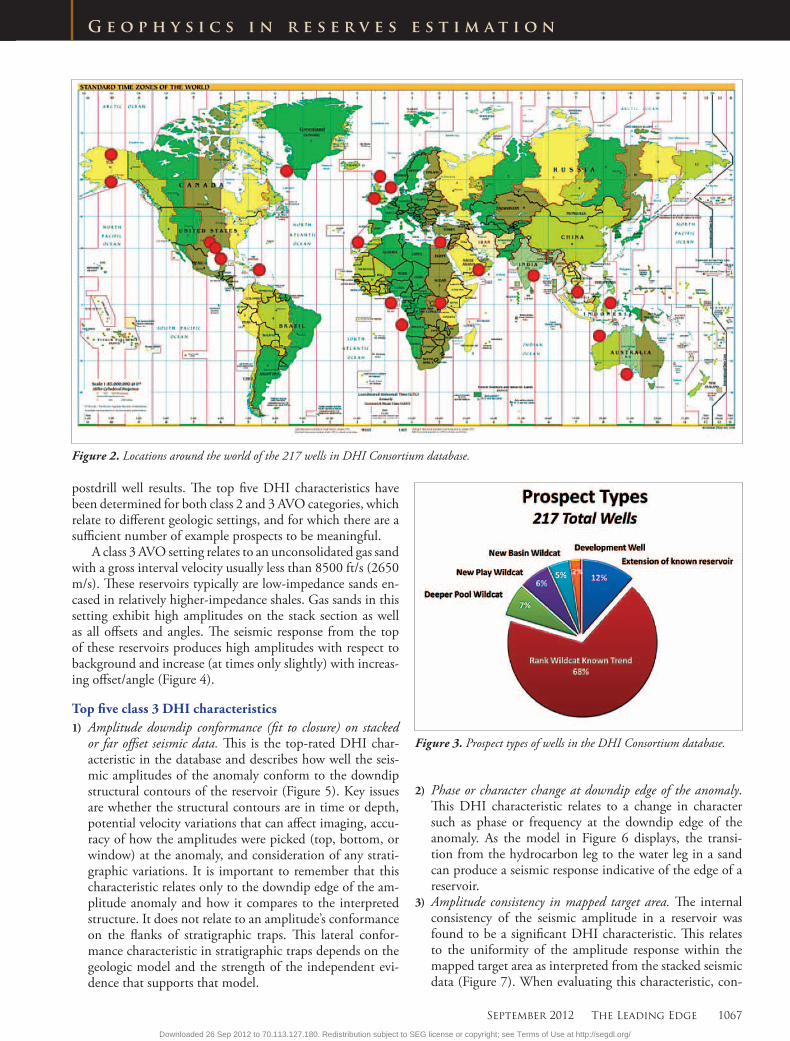
These companies have supplied 217 prospects from around the world (Figure 2) with approximately an equal number of successes, dry holes, and objective reservoirs rang-ing in age from Triassic to Pleistocene. The prospects range in size from less than 100 acres to greater than 10,000 acres and depths from 2000 to more than 20,000 ft. This database is predominantly made up of exploratory wells with only 14% coming from “development” or “extension to known reser-voir” wells (Figure 3). The closure types include structural (59%), stratigraphic (26%), and combination structural/stratigraphic (15%) traps.
Critical in the evaluation of DHI characteristics is an un-derstanding of the geologic setting. Because expected DHI responses vary depending on the geologic setting, the pros-pects in the database are categorized by AVO classes 1–4 as displayed in Figure 4 (Rutherford and Williams, 1989; Cast-agna et al., 1998). However, 76% of the prospects are class 3 and 22% are class 2, with only a few from class 1 and 4 settings.
A general description of the input information and quan-tified output for this database are described in Table 1.
There are several ways the most important DHI charac-teristics can be determined from the well results. The follow-ing list is a result of when a DHI characteristic was rated to be a 4 or 5 on a scale of 1–5, with 1 being the worst and 5 the best. These results were then correlated with whether the wells were successful or dry holes. This approach eliminates any scaling or weighting effects and compares only whether the DHI characteristic is strongly correlated with the actual
Figure 1. DHI interpretation and workflow concept.
Table 1. General input and quantified output from DHI analysis process. Note that the input parameters are not necessarily linked directly to the corresponding quantified output row.
Input Quantified output
Geologic context Composite data quality scoreInitial Pg (product of geologic chance factors independent of amplitude as a DHI)
DHI index (Pg specifically as-sociated with DHI anomaly)
Seismic data quality Final PgRock physics data quality Calibration of final PgDHI characteristics observations Volume calculation impact
Downloaded 26 Sep 2012 to 70.113.127.180. Redistribution subject to SEG license or copyright; see Terms of Use at http://segdl.org/
September 2012 The Leading Edge 1067
G e o p h y s i c s i n r e s e r v e s e s t i m a t i o n
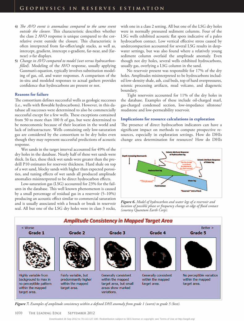
2) Phase or character change at downdip edge of the anomaly. This DHI characteristic relates to a change in character such as phase or frequency at the downdip edge of the anomaly. As the model in Figure 6 displays, the transi-tion from the hydrocarbon leg to the water leg in a sand can produce a seismic response indicative of the edge of a reservoir.
3) Amplitude consistency in mapped target area. The internal consistency of the seismic amplitude in a reservoir was found to be a significant DHI characteristic. This relates to the uniformity of the amplitude response within the mapped target area as interpreted from the stacked seismic data (Figure 7). When evaluating this characteristic, con-
postdrill well results. The top five DHI characteristics have been determined for both class 2 and 3 AVO categories, which relate to different geologic settings, and for which there are a sufficient number of example prospects to be meaningful.
A class 3 AVO setting relates to an unconsolidated gas sand with a gross interval velocity usually less than 8500 ft/s (2650 m/s). These reservoirs typically are low-impedance sands en-cased in relatively higher-impedance shales. Gas sands in this setting exhibit high amplitudes on the stack section as well as all offsets and angles. The seismic response from the top of these reservoirs produces high amplitudes with respect to background and increase (at times only slightly) with increas-ing offset/angle (Figure 4).
Top five class 3 DHI characteristics1) Amplitude downdip conformance (fit to closure) on stacked
or far offset seismic data. This is the top-rated DHI char-acteristic in the database and describes how well the seis-mic amplitudes of the anomaly conform to the downdip structural contours of the reservoir (Figure 5). Key issues are whether the structural contours are in time or depth, potential velocity variations that can affect imaging, accu-racy of how the amplitudes were picked (top, bottom, or window) at the anomaly, and consideration of any strati-graphic variations. It is important to remember that this characteristic relates only to the downdip edge of the am-plitude anomaly and how it compares to the interpreted structure. It does not relate to an amplitude’s conformance on the flanks of stratigraphic traps. This lateral confor-mance characteristic in stratigraphic traps depends on the geologic model and the strength of the independent evi-dence that supports that model.
Figure 2. Locations around the world of the 217 wells in DHI Consortium database.
Figure 3. Prospect types of wells in the DHI Consortium database.
Downloaded 26 Sep 2012 to 70.113.127.180. Redistribution subject to SEG license or copyright; see Terms of Use at http://segdl.org/

1068 The Leading Edge September 2012
G e o p h y s i c s i n r e s e r v e s e s t i m a t i o n
sideration should be given to possible faulting and strati-graphic changes that may modify internal consistency.
4) Flat spots. This characteristic represents the seismic re-sponse at a hydrocarbon contact that presumably is rela-tively flat. This contact can be at the gas/oil contact, oil/water contact, or gas/water contact. The gross reservoir thickness of the hydrocarbon unit must be greater than the tuning thickness (vertical resolution) to image a flat spot. Extreme care must be taken because the base or edge of channels, low-angle faults, diagenetic boundaries, or even processing artifacts are often misinterpreted as flat spots. Low-saturation gas in a reservoir can also produce a flat spot and this possibility is usually assessed by regional geo-logic studies.
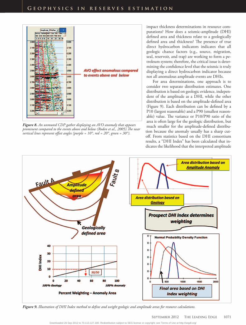
5) Excluding possible stacked pays, the AVO response is anoma-lous compared to events above and below. On prestack data, usually gathers, this characteristic refers to whether there are high-amplitude events above and below the targeted anomaly that look similar (Figure 8). The reasoning is that the anomaly is relatively unique suggesting a hydrocarbon bearing reservoir.
A class 2 setting contains gas sands more consolidated than class 3 sands with gross interval velocities usually be-tween 8500 ft/s and 12,000 ft/s (2650 m/s and 3650 m/s). The acoustic impedances of these gas sands and encasing shales are about equal. The intercept or near-offset amplitude can vary from a weak positive to a weak negative. The AVO effect can be strongly more negative with offset (large gradi-ent) in these settings (Figure 4).
Top five class 2 DHI characteristics1) Amplitude downdip conformance (fit to closure) on far-offset
seismic data. The principles behind this characteristic are the same as the top characteristic for class 3 settings, but for class 2 prospects this is usually evaluated on the far offset seismic data.
2) Consistency in mapped target area (typically on gathers, far-offset/angle stacks, or windowed attributes). Internal consis-tency of the seismic amplitude identified on far-offset data was found to be an important DHI characteristic for class 2 rocks just as it is for class 3 rocks.
3) AVO observations using gathers, far-offset/angle stacks, or windowed attributes. This characteristic relates to an inter-preter’s confidence that the AVO response is proper for a class 2 setting. In other words, the near-offset is low in am-plitude (small peak or trough) and the amplitude increases in negative amplitude with offset (Figure 4). Noisy gath-ers, incorrect NMO corrections, multiples, insufficient offset during acquisition, and processing artifacts often complicate evaluation of this characteristic.
Figure 4. (top) AVO classes based on amplitude change with offset from the top of gas sands (Rutherford and Williams, 1989; Castagna et al., 1998). (bottom) Angle gathers, zero-offset, and stack responses for typical class 2 and 3 AVO classes.
Figure 5. Examples of amplitude conformance to the downdip structural contours from grade 1 (worst) to grade 5 (best).
Downloaded 26 Sep 2012 to 70.113.127.180. Redistribution subject to SEG license or copyright; see Terms of Use at http://segdl.org/

G e o p h y s i c s i n r e s e r v e s e s t i m a t i o n
Downloaded 26 Sep 2012 to 70.113.127.180. Redistribution subject to SEG license or copyright; see Terms of Use at http://segdl.org/
1070 The Leading Edge September 2012
G e o p h y s i c s i n r e s e r v e s e s t i m a t i o n
4) The AVO event is anomalous compared to the same event outside the closure. This characteristic describes whether the class 2 AVO response is unique compared to the cor-relative event outside the closure. This characteristic is often interpreted from far-offset/angle stacks, as well as, intercept, gradient, intercept x-gradient, far-near, and (far-near) x-far displays.
5) Change in AVO compared to model (wet versus hydrocarbon-filled). Modeling of the AVO response, usually applying Gassman’s equation, typically involves substitution model-ing of gas, oil, and water responses. A comparison of the in-situ and modeled responses to actual gathers provides confidence that hydrocarbons are present or not.
Reasons for failureThe consortium defines successful wells as geologic successes (i.e., wells with flowable hydrocarbons). However, in this da-tabase all successes were determined to also be commercially successful except for a few wells. These exceptions contained from 50 to more than 100 ft of gas, but were determined to be noneconomic because of their location in the world and lack of infrastructure. Wells containing only low-saturation gas are considered by the consortium to be dry holes even though they may represent successful predictions of acoustic response.
Wet sands in the target interval accounted for 49% of the dry holes in the database. Nearly half of these wet sands were thick. In fact, these thick wet sands were greater than the pre-drill P10 estimates for reservoir thickness. Hard shale on top of a wet sand, blocky sands with higher than expected porosi-ties, and tuning effects of wet sands all produced amplitude anomalies misinterpreted to be direct hydrocarbon effects.
Low-saturation gas (LSG) accounted for 23% for the fail-ures in the database. This well known phenomenon is caused by a small percentage of residual gas in a reservoir (5–10%) producing an acoustic effect similar to commercial saturation and is usually associated with a breach or break in reservoir seal. All but one of the LSG dry holes were in class 3 rocks,
with one in a class 2 setting. All but one of the LSG dry holes were in normally pressured sediment columns. Four of the LSG wells exhibited acoustic flat spots indicative of a paleo hydrocarbon contact. Low vertical effective stress caused by undercompaction accounted for several LSG results in deep-water settings, but was also found where a relatively young sediment column overlaid the amplitude anomaly. Even though not dry holes, several wells exhibited hydrocarbons, usually gas, overlying a LSG column in the sand.
No reservoir present was responsible for 17% of the dry holes. Amplitudes misinterpreted to be hydrocarbons includ-ed low-density shale, ash, coal beds, top of hard overpressures, seismic processing artifacts, mud volcano, and diagenetic boundary.
Tight reservoirs accounted for 11% of the dry holes in the database. Examples of these include oil-charged marl, gas-charged condensed section, low-impedance siltstone/mudstone and low-permeability reservoir.
Implications for resource calculations in explorationThe presence of direct hydrocarbon indicators can have a significant impact on methods to compute prospective re-sources, especially in exploration settings. How do DHIs change area determination for resources? How do DHIs
Figure 7. Examples of amplitude consistency within a defined DHI anomaly from grade 1 (worst) to grade 5 (best).
Figure 6. Model of hydrocarbon and water legs of a reservoir and location of possible phase or frequency change at edge of fluid contact (courtesy Quantum Earth Corp).
Downloaded 26 Sep 2012 to 70.113.127.180. Redistribution subject to SEG license or copyright; see Terms of Use at http://segdl.org/
September 2012 The Leading Edge 1071
G e o p h y s i c s i n r e s e r v e s e s t i m a t i o n
Figure 8. An unmuted CDP gather displaying an AVO anomaly that appears prominent compared to the events above and below (Roden et al., 2005).The near vertical lines represent offset angles (purple = 10°, red = 20°, green = 30°).
Figure 9. Illustration of DHI Index method to define and weight geologic and amplitude areas for resource calculations.
impact thickness determinations in resource com-putations? How does a seismic-amplitude (DHI) defined area and thickness relate to a geologically defined area and thickness? The presence of true direct hydrocarbon indicators indicates that all geologic chance factors (e.g., source, migration, seal, reservoir, and trap) are working to form a pe-troleum system; therefore, the critical issue is deter-mining the confidence level that the seismic is truly displaying a direct hydrocarbon indicator because not all anomalous amplitude events are DHIs.
For area determinations, one approach is to consider two separate distribution estimates. One distribution is based on geologic evidence, indepen-dent of the amplitude as a DHI, while the other distribution is based on the amplitude-defined area (Figure 9). Each distribution can be defined by a P10 (largest reasonable) and a P90 (smallest reason-able) value. The variance or P10/P90 ratio of the area is often large for the geologic distribution, but much smaller for the amplitude-defined distribu-tion because the anomaly usually has a sharp cut-off. From statistics based on the DHI consortium results, a “DHI Index” has been calculated that in-dicates the likelihood that the interpreted amplitude
Downloaded 26 Sep 2012 to 70.113.127.180. Redistribution subject to SEG license or copyright; see Terms of Use at http://segdl.org/

1072 The Leading Edge September 2012
G e o p h y s i c s i n r e s e r v e s e s t i m a t i o n
Figure 10. DHI Index values color-coded by drilling outcomes. Note that above 20% almost all wells are successful. There are negative DHI Index values, usually associated with dry holes, where DHI characteristics should be present, but were absent.
Figure 11. Seismic inversion techniques typically applied from exploration to development.
anomaly is truly a direct hydrocarbon indicator. This “DHI Index” can be used as a relative weighting factor for the two distribution estimates.
The histograms of Figure 10 show that, when the DHI
Index is more than 20%, essentially all wells are successful. To get a DHI Index of 20% or higher requires having numer-ous positive DHI characteristics. Therefore, using this logic, prospects with a DHI Index of 20% or larger employ the DHI-defined area, whereas, a DHI Index of 0% or less em-ploy the geologically defined area (Figure 9). A DHI Index of 0% or less indicates there is no DHI element at all in the area determination. When a prospect has a DHI Index between 0% and 20%, the area is defined by a simple linear weighting (e.g., a DHI Index of 10% would have a 50/50 weighting of geology and amplitude-defined areas) between the two distri-bution estimates.
For thickness determinations, similar to the DHI Index approach for area, two thickness distributions can be estimat-ed. One is defined geologically and one by the amplitude-de-fined thickness. The geologically defined distribution should be based on well control, sand studies, depositional trends, and usually involves constructing regional and local sand isopachs consistent with the depositional model in terms of reservoir shape and thickness. From the combination of sand isopachs, depositional environment determinations, models and stratigraphy studies, an estimate of the P10 and P90 aver-age net pay thicknesses can be calculated.
For the amplitude-defined thickness, the interpreter first needs to determine whether the anomaly is above tuning, be-low tuning, or both. Above tuning, the thickness is a func-
Downloaded 26 Sep 2012 to 70.113.127.180. Redistribution subject to SEG license or copyright; see Terms of Use at http://segdl.org/

September 2012 The Leading Edge 1073
G e o p h y s i c s i n r e s e r v e s e s t i m a t i o n
tion of the time separation between the top and bottom of the anomaly. Gross pay maps (isochrons) can be generated for the P10 and P90 cases including any geometric factors. An estimated net-to-gross and interval velocity are applied to determine the final thickness distributions. Below tun-ing, in the ideal situation, the composite amplitude from the top and bottom of the bed decreases linearly with thickness starting from tuning thickness. The amplitude should be calibrated with well control and stratigraphy studies. Below tuning, a starting point P10 could be the tuning thickness and a P90 could be the detection limit (approximately 1/30 wavelength of the dominant frequency). Appropriate interval velocities may need to be applied for thickness conversions. Below tuning, the composite amplitude usually incorporates any net-to-gross effects. Once a geologically defined thick-ness distribution and a seismic amplitude-defined thickness are determined, the DHI Index can be used to determine weighting of these two distributions. It can be more difficult to separate and differentiate between a geologically and am-plitude-defined thickness as compared to interpreting distri-butions for area. In this situation, it may be more appropriate to combine geologic and amplitude thickness information and use one distribution without weighting to compute re-sources. Spectral decomposition has been found to be helpful in certain situations to help determine thickness trends.
Employing the DHI Index method to determine area and
thickness for resource calculations is one approach that gives credit to both geologically and amplitude defined distribu-tions. However, it is not uncommon in strong amplitude-driven plays to employ the amplitude-defined distributions only, especially for area. The logic here is that the presence of amplitudes is defining the reservoir and the geologic dis-tributions do not apply. Care should be taken in that all am-plitudes are not DHIs and not all geologic settings exhibit DHIs equally. In addition, even if there is evidence that the area can be narrowly estimated, there will often be significant remaining uncertainty in resource size because of the variance in average net pay thickness and recovery factor estimates.
Implications for reserve calculationsThe U. S. Securities and Exchange Commission (SEC) de-fines “proved oil and gas reserves” in part as “those quantities of oil and gas, which, by analysis of geosciences and engineer-ing data, can be estimated with reasonable certainty to be economically producible—from a given date forward, from known reservoirs, and under existing economic conditions, operating methods, and government regulations—prior to the time at which contracts providing the right to operate expire, unless evidence indicates that renewal is reasonably certain, regardless of whether deterministic or probabilistic methods are used for the estimation.” Unlike resource cal-culations in exploration, reserve calculations have had a well
Downloaded 26 Sep 2012 to 70.113.127.180. Redistribution subject to SEG license or copyright; see Terms of Use at http://segdl.org/

1074 The Leading Edge September 2012
G e o p h y s i c s i n r e s e r v e s e s t i m a t i o n
or wells drilled to confirm geologic conditions and to some degree seismic amplitude features. Therefore the interpreta-tion of DHI features relates to the determination of “reliable technology” as defined by the SEC. As defined by the SEC, “reliable technology is a grouping of one or more technolo-gies (including computational methods) that has been field tested and has been demonstrated to provide reasonably cer-tain results with consistency and repeatability in the forma-tion being evaluated or in an analogous formation.” There-fore for DHI characteristics to qualify as reliable technology requires the correlation of amplitude features with well con-trol, reservoir engineering tests, known geologic trends and stratigraphy.
Even with well control and substantial geologic control of thickness and area extents, care should be taken in incorpo-rating DHI information from seismic data. Considerations for amplitude anomalies and reserve determinations include:
1) Strong amplitude is primarily at wedge where tuning oc-curs, weaker amplitude updip
2) Stratigraphic trap where conventional downdip and updip limits do not apply
3) Reservoir thins updip, bald structure4) Velocity tilt can affect conformance to closure interpreta-
tions5) Faults affecting amplitudes for area determinations6) Stratigraphic changes across field7) Masking of amplitudes from bright spots above prospect8) Amplitude effects from low-saturation gas downdip of
proven pay in the same reservoir9) Beware of large column heights for gas reservoirs10) Data issues, such as prospect at edge of survey, complicate
area estimates
In development, seismic technologies such as spectral decomposition, neural networks, statistical approaches, and advanced seismic inversion techniques are often applied to help determine reserves. The transition from exploration to development and the use of seismic inversion requires the incorporation of all available geologic, seismic, and engineer-ing data in an attempt to discriminate specifically between lithology, porosity, and fluid effects (Figure 11) and how these parameters relate to reserve calculations.
ConclusionsOver the past 11 years, 41 oil companies have contributed data for the evaluation of more than 200 drilled prospects (including assessment of the associated technical informa-tion and drilling results). The subsequent database developed from these assessments has enabled the identification of the pertinent aspects of direct hydrocarbon indicators and their impact on risking and resource/reserve determination. This database is composed primarily of exploratory wells (86%) and has direct relevance for computing resources in explora-tion. However, the lessons learned from this database are also pertinent for reserve assessment in development because an understanding of the most important DHI characteristics,
reasons for failure, and potential pitfalls in DHI interpreta-tion provide valuable information in the reserve assessment process. Critical in the evaluation of DHI characteristics is the pertinent technical approaches employed and their cali-bration to known drilling results. However, even in devel-opment settings with a certain amount of well control for calibration, DHI interpretation requires a consistent and systematic evaluation procedure, including recognition of potential pitfalls and an understanding of the cause of the DHIs and their significance in reserve assessment.
ReferencesCastagna, J., H. Swan, and D. Foster, 1998, Framework for AVO
gradient and intercept interpretation: Geophysics, 63, no. 3, 948–956, http://dx.doi.org/10.1190/1.1444406.
Forrest, M., R. Roden, and R. Holeywell, 2010, Risking seismic am-plitude anomaly prospects based on database trends: The Leading Edge, 29, 936–940, http://dx.doi.org/ 10.1190/ 1.3422455.
Roden, R., M. Forrest, and R. Holeywell, 2005, The impact of seismic amplitudes on prospect risk analysis: The Leading Edge, 24, no. 7, 706–711, http://dx.doi.org/10.1190/1.1993262.
Roden, R., J. Castagna, and G. Jones, 2005, The impact of prestack data phase on the AVO interpretation workflow-A case study: The Leading Edge, 24, 890–895. http://dx.doi.org/10.1190/1.2056369.
Rutherford, S. E. and R. H. Williams, 1989, Amplitude versus off-set variation in gas sands: Geophysics, 54, no. 6, 680–688, http://dx.doi.org/10.1190/1.1442696.
U. S. Securities and Exchange Commission, 2008, Modernization of oil and gas reporting, December 31.
Acknowledgments: The authors thank the member companies of the DHI Consortium for providing invaluable information neces-sary to develop the resulting interpretation process and prospect database.
Corresponding author: [email protected]
Downloaded 26 Sep 2012 to 70.113.127.180. Redistribution subject to SEG license or copyright; see Terms of Use at http://segdl.org/

G e o p h y s i c s i n r e s e r v e s e s t i m a t i o n
Downloaded 26 Sep 2012 to 70.113.127.180. Redistribution subject to SEG license or copyright; see Terms of Use at http://segdl.org/