relay outputs or isolated inputs terminal board series · pdf filerelay outputs or isolated...
TRANSCRIPT

TB-24P/24R/16P8RRelay Outputs or Isolated Inputs
Terminal Board Series


@Copyright 1995~1998 ADLink Technology Inc.All Rights Reserved.
Manual first edition: 15, August 1995Manual second edition: 01, March 1998
The information in this document is subject to change without prior notice inorder to improve reliability, design and function and does not represent acommitment on the part of the manufacturer.
In no event will the manufacturer be liable for direct, indirect, special,incidental, or consequential damages arising out of the use or inability to usethe product or documentation, even if advised of the possibility of suchdamages.
This document contains proprietary information protected by copyright. Allrights are reserved. No part of this manual may be reproduced by anymechanical, electronic, or other means in any form without prior writtenpermission of the manufacturer.
TrademarksTB-24P, TB-24R, TB-16P8R are registered trademark of ADLink TechnologyInc., other product names mentioned herein are used for identification purposesonly and may be trademarks and/or registered trademarks of their respectivecompanies.


Contents • i
CONTENTS
How to Use This Guide ....................................... iii
TB-24P : 24 Opto-isolated Digital InputsTerminal Board .............................................1
1.1 Introductions ..........................................................1
1.2 Specifications.........................................................1
1.3 Descriptions ...........................................................2
TB-24R : 24 Relay Outputs Terminal Board......7
2.1 Introduction ............................................................7
2.2 Specification...........................................................7
2.3 Description .............................................................8
TB-16P8R : 16 Opto-isolated Inputs & 8 RelayOutputs Terminal Board.............................13
3.1 Introduction ..........................................................13
3.2 Specification.........................................................13
3.3 Description ...........................................................14
Product Warranty/Service .................................19


How to Use This Guide • iii
How to Use This Guide
This manual is designed to help you use the TB-24P/24R/16P8R. The manual describes how to modify varioussettings on the TB-24P/24R/16P8R card to meet yourrequirements.
• Chapter 1, "TB-24P : 24 Opto-isolated Digital Inputs TerminalBoard", gives an overview of the TB-24P's features,description, and specifications.
• Chapter 2, "TB-24R : 24 Relay Outputs Terminal Board",gives an overview of the TB-24R's features, description, andspecifications.
• Chapter 3, "TB-16P8R ; 16 Opto-isolated Digital Inputs & 8Relay Outputs Terminal Board", gives an overview of the TB-16P8R features, description, and specification

TB-24P • 1
1
TB-24P : 24 Opto-isolatedDigital Inputs Terminal Board
1.1 Introductions
TB - 24P is an input extension board with 24 isolated photocouplers. CN1, CN2, CN3 and CN4 are terminal blocks toconnect with external devices. CN5 is a 50 pins connector toconnect with opto-22 compatible connector, such as ACL-7124, ACL-7122, PET-48DIO, etc. All input ports are with LEDindicators.
1.2 SpecificationsIndication Display : 24 LEDs for input indicationInput electrical characteristically
Logic input low voltage : <0.8 V DCLogic input high voltage : +3V DC to +24V DCLogic input high current : 6.3mA to 50mALogic "1" : Voltage input highLogic "0" : Voltage input low
Isolation voltage : 2500V DC
2 • TB-24P
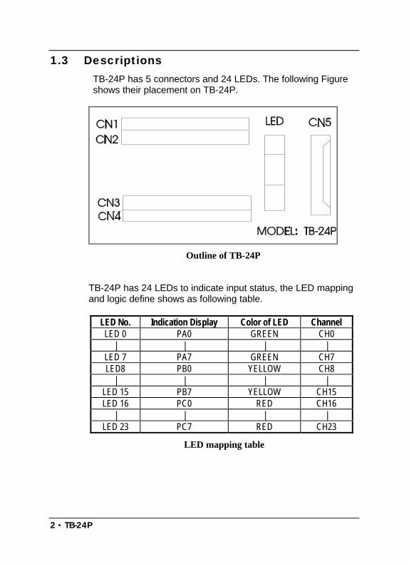
1.3 DescriptionsTB-24P has 5 connectors and 24 LEDs. The following Figureshows their placement on TB-24P.
Outline of TB-24P
TB-24P has 24 LEDs to indicate input status, the LED mappingand logic define shows as following table.
LED No. Indication Display Color of LED ChannelLED 0 PA0 GREEN CH0
| | | |LED 7 PA7 GREEN CH7LED8 PB0 YELLOW CH8
| | | |LED 15 PB7 YELLOW CH15LED 16 PC0 RED CH16
| | | |LED 23 PC7 RED CH23
LED mapping table

TB-24P • 3
Logic "1" LED " ON"Logic "0" LED "OFF"
Logic define
Each input channel can connect with opto-22 compatibleDigital I/O board, such as ACL-7122, PET-48DIO, etc. directlyor through photo coupler, and the upper of each photo couplerhas a jumper to select.
The position of each setting jumper
4 • TB-24P
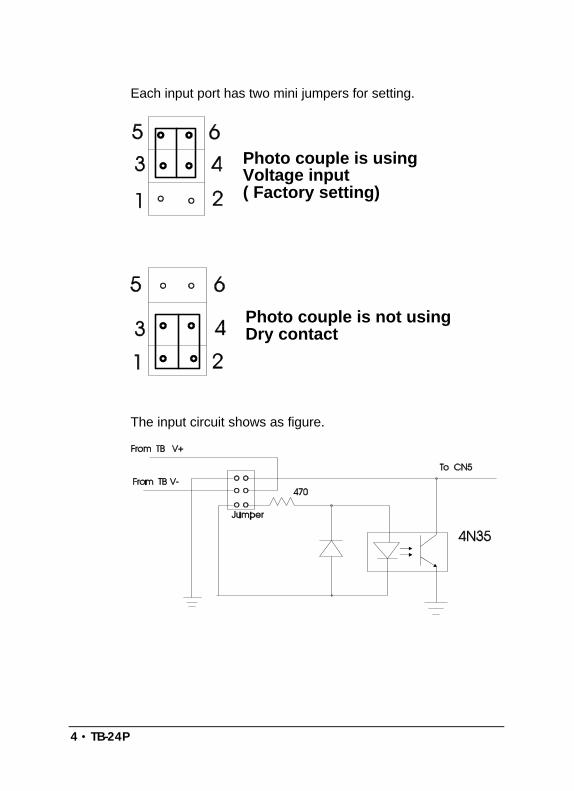
Each input port has two mini jumpers for setting.
Photo couple is usingVoltage input( Factory setting)
Photo couple is not usingDry contact
The input circuit shows as figure.
TB-24P • 5
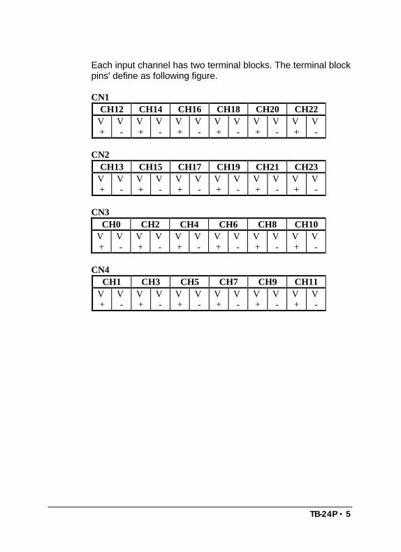
Each input channel has two terminal blocks. The terminal blockpins' define as following figure.
CN1CH12 CH14 CH16 CH18 CH20 CH22
V+
V-
V+
V-
V+
V-
V+
V-
V+
V-
V+
V-
CN2CH13 CH15 CH17 CH19 CH21 CH23
V+
V-
V+
V-
V+
V-
V+
V-
V+
V-
V+
V-
CN3CH0 CH2 CH4 CH6 CH8 CH10
V+
V-
V+
V-
V+
V-
V+
V-
V+
V-
V+
V-
CN4CH1 CH3 CH5 CH7 CH9 CH11
V+
V-
V+
V-
V+
V-
V+
V-
V+
V-
V+
V-
6 • TB-24P
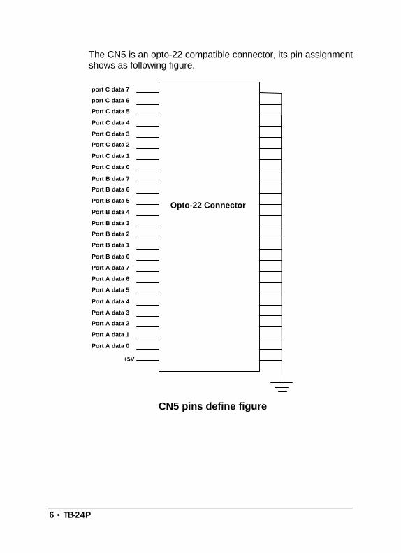
The CN5 is an opto-22 compatible connector, its pin assignmentshows as following figure.
port C data 7
port C data 6
Port B data 7
Port A data 7
+5V
Port B data 6
Port B data 5
Port B data 4
Port B data 3
Port B data 2
Port B data 1
Port B data 0
Port A data 6
Port A data 5
Port A data 4
Port A data 3
Port A data 2
Port A data 1
Port A data 0
Port C data 5
Port C data 4
Port C data 3
Port C data 2
Port C data 1
Port C data 0
Opto-22 Connector
CN5 pins define figure

TB-24R • 7
2
TB-24R : 24 Relay Outputs TerminalBoard
2.1 IntroductionTB - 24R is an output extension board with 24 relays. CN1,CN2, CN3 and CN4 are terminal blocks to connect withexternal devices. CN5 connect with external power source. TB-24R/12 using +12V power, but TB-24R/24 using +24V power.CN6 is to connect the opto-22 compatible connector, such asACL-7122, ACL-7124, PET-48DIO, etc.
2.2 SpecificationIndication display : 24 LEDsRelay type : High sensitive 1500 V FCC surge with
standing miniature relay.Relay form : SPDTContact rating :
Max. switching power 60 W, 125 VAMax. switching voltage 220 V DC, 250 V ACMax. switching current 2 A DC, ACMax. carrying current 3 A DC, ACUL/CSA rating 0.6 A 125 V ACUL/CSA rating 0.6 A 110 V DCUL/CSA rating 2 A 30 V DC
Coil voltage : 12 V DC for TB-24R/12: 24V DC for TB-24R/24
8 • TB-24R
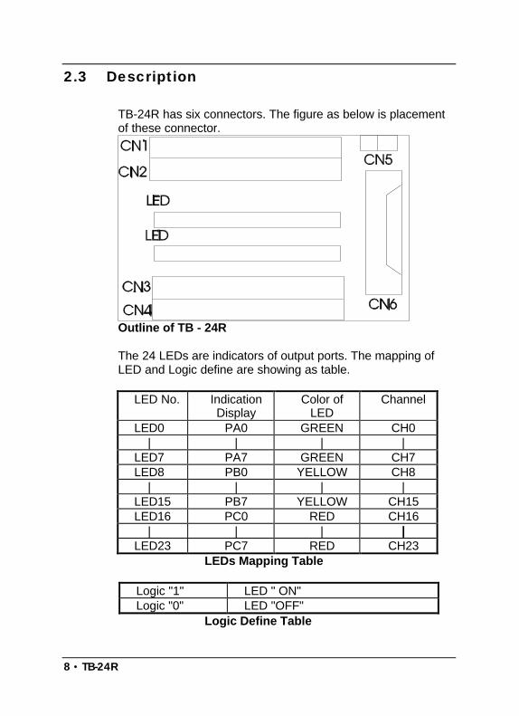
2.3 Description
TB-24R has six connectors. The figure as below is placementof these connector.
Outline of TB - 24R
The 24 LEDs are indicators of output ports. The mapping ofLED and Logic define are showing as table.
LED No. IndicationDisplay
Color ofLED
Channel
LED0 PA0 GREEN CH0 | | | |LED7 PA7 GREEN CH7LED8 PB0 YELLOW CH8 | | | |LED15 PB7 YELLOW CH15LED16 PC0 RED CH16 | | | |LED23 PC7 RED CH23
LEDs Mapping Table
Logic "1" LED " ON"Logic "0" LED "OFF"
Logic Define Table
TB-24R • 9
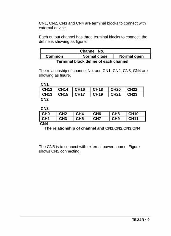
CN1, CN2, CN3 and CN4 are terminal blocks to connect withexternal device.
Each output channel has three terminal blocks to connect, thedefine is showing as figure.
Channel No.Common Normal close Normal open
Terminal block define of each channel
The relationship of channel No. and CN1, CN2, CN3, CN4 areshowing as figure.
CN1CH12 CH14 CH16 CH18 CH20 CH22CH13 CH15 CH17 CH19 CH21 CH23
CN2
CN3CH0 CH2 CH4 CH6 CH8 CH10CH1 CH3 CH5 CH7 CH9 CH11
CN4The relationship of channel and CN1,CN2,CN3,CN4
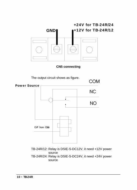
The CN5 is to connect with external power source. Figureshows CN5 connecting.
10 • TB-24R
+12VGND
CN5 connecting
The output circuit shows as figure.
+12V
TB-24R/12: Relay is DSIE-S-DC12V, it need +12V powersource
TB-24R/24: Relay is DSIE-S-DC24V, it need +24V powersource
+24V for TB-24R/24+12V for TB-24R/12
Power Source
TB-24R • 11
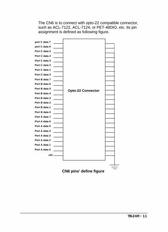
The CN6 is to connect with opto-22 compatible connector,such as ACL-7122, ACL-7124, or PET-48DIO, etc. Its pinassignment is defined as following figure.
port C data 7
port C data 6
Port B data 7
Port A data 7
+5V
Port B data 6
Port B data 5
Port B data 4
Port B data 3
Port B data 2
Port B data 1
Port B data 0
Port A data 6
Port A data 5
Port A data 4
Port A data 3
Port A data 2
Port A data 1
Port A data 0
Port C data 5
Port C data 4
Port C data 3
Port C data 2
Port C data 1
Port C data 0
Opto-22 Connector
CN6 pins' define figure

TB-16P8R • 13
3
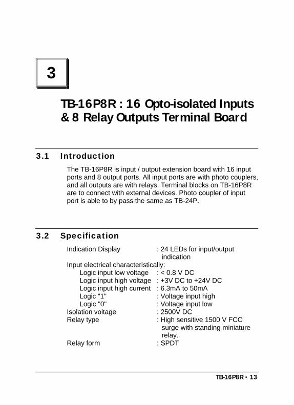
TB-16P8R : 16 Opto-isolated Inputs& 8 Relay Outputs Terminal Board
3.1 IntroductionThe TB-16P8R is input / output extension board with 16 inputports and 8 output ports. All input ports are with photo couplers,and all outputs are with relays. Terminal blocks on TB-16P8Rare to connect with external devices. Photo coupler of inputport is able to by pass the same as TB-24P.
3.2 SpecificationIndication Display : 24 LEDs for input/output
indicationInput electrical characteristically:
Logic input low voltage : < 0.8 V DCLogic input high voltage : +3V DC to +24V DCLogic input high current : 6.3mA to 50mALogic "1" : Voltage input highLogic "0" : Voltage input low
Isolation voltage : 2500V DCRelay type : High sensitive 1500 V FCC
surge with standing miniaturerelay.
Relay form : SPDT
14 • TB-16P8R
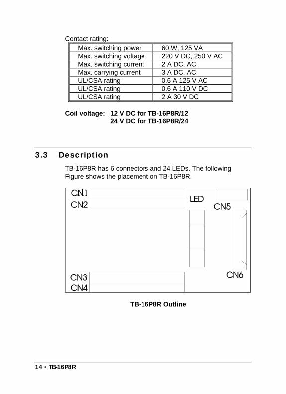
Contact rating:Max. switching power 60 W, 125 VAMax. switching voltage 220 V DC, 250 V ACMax. switching current 2 A DC, ACMax. carrying current 3 A DC, ACUL/CSA rating 0.6 A 125 V ACUL/CSA rating 0.6 A 110 V DCUL/CSA rating 2 A 30 V DC
Coil voltage: 12 V DC for TB-16P8R/1224 V DC for TB-16P8R/24
3.3 DescriptionTB-16P8R has 6 connectors and 24 LEDs. The followingFigure shows the placement on TB-16P8R.
TB-16P8R Outline
TB-16P8R • 15
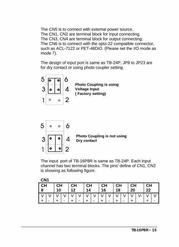
The CN5 is to connect with external power source.The CN1, CN2 are terminal block for input connecting.The CN3, CN4 are terminal block for output connecting.The CN6 is to connect with the opto-22 compatible connector,such as ACL-7122 or PET-48DIO. (Please set the I/O mode asmode 7).
The design of input port is same as TB-24P. JP8 to JP23 arefor dry contact or using photo coupler setting.
Photo Coupling is usingVoltage Input( Factory setting)
Photo Coupling is not usingDry contact
The input port of TB-16P8R is same as TB-24P. Each inputchannel has two terminal blocks. The pins' define of CN1, CN2is showing as following figure.
CN1CH8
CH10
CH12
CH14
CH16
CH18
CH20
CH22
V+
V-
V+
V-
V+
V-
V+
V-
V+
V-
V+
V-
V+
V- V+
V-
16 • TB-16P8R
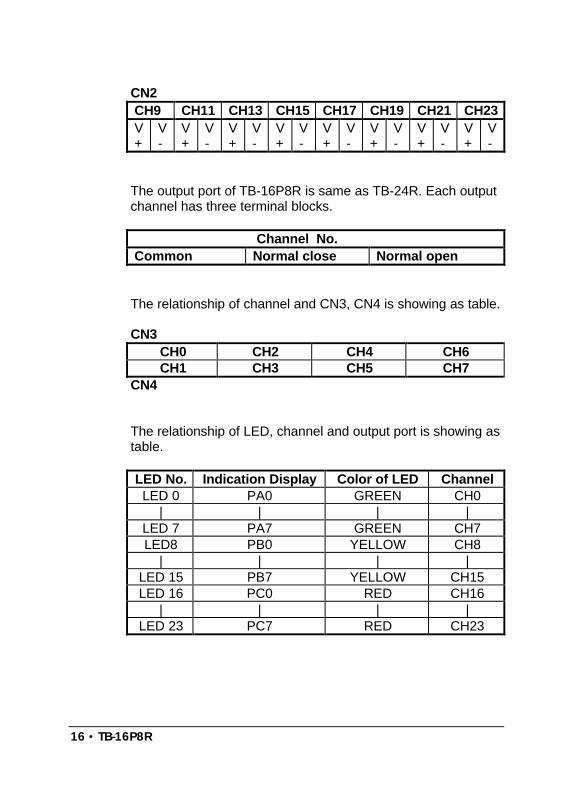
CN2CH9 CH11 CH13 CH15 CH17 CH19 CH21 CH23V+
V-
V+
V-
V+
V-
V+
V-
V+
V-
V+
V-
V+
V-
V+
V-
The output port of TB-16P8R is same as TB-24R. Each outputchannel has three terminal blocks.
Channel No.Common Normal close Normal open
The relationship of channel and CN3, CN4 is showing as table.
CN3CH0 CH2 CH4 CH6CH1 CH3 CH5 CH7
CN4
The relationship of LED, channel and output port is showing astable.
LED No. Indication Display Color of LED ChannelLED 0 PA0 GREEN CH0
| | | |LED 7 PA7 GREEN CH7LED8 PB0 YELLOW CH8
| | | |LED 15 PB7 YELLOW CH15LED 16 PC0 RED CH16
| | | |LED 23 PC7 RED CH23

TB-16P8R • 17
The CN5 is to connect external power source. Figure showsconnecting.
+12VGND
TB-16P8R/12: Relay is DSIE-S-DC12V, it need +12V powersource
TB-16P8R/24: Relay is DSIE-S-DC24V, it need +24V powersource
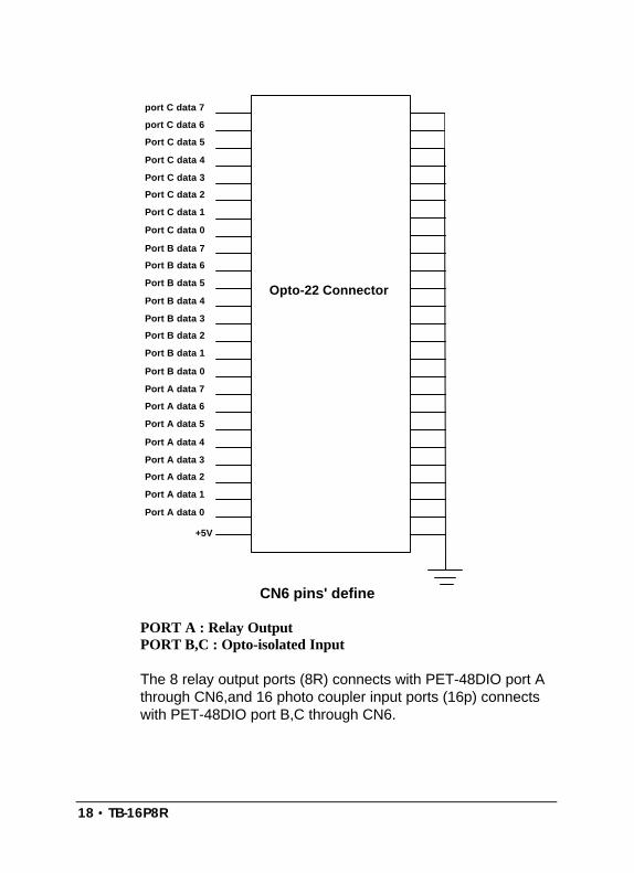
The CN6 is connector to connect with opto-22 compatibleconnector. Figure shows CN6 pins' define.
+24V for TB-24R/24+12V for TB-24R/12
18 • TB-16P8R
port C data 7
port C data 6
Port B data 7
Port A data 7
+5V
Port B data 6
Port B data 5
Port B data 4
Port B data 3
Port B data 2
Port B data 1
Port B data 0
Port A data 6
Port A data 5
Port A data 4
Port A data 3
Port A data 2
Port A data 1
Port A data 0
Port C data 5
Port C data 4
Port C data 3
Port C data 2
Port C data 1
Port C data 0
Opto-22 Connector
CN6 pins' define
PORT A : Relay OutputPORT B,C : Opto-isolated Input
The 8 relay output ports (8R) connects with PET-48DIO port Athrough CN6,and 16 photo coupler input ports (16p) connectswith PET-48DIO port B,C through CN6.

Product Warranty/Service • 18
Product Warranty/Service
Seller warrants that equipment furnished will be free form defectsin material and workmanship for a period of one year from theconfirmed date of purchase of the original buyer and that uponwritten notice of any such defect, Seller will, at its option, repairor replace the defective item under the terms of this warranty,subject to the provisions and specific exclusions listed herein.
This warranty shall not apply to equipment that has beenpreviously repaired or altered outside our plant in any way as to,in the judgment of the manufacturer, affect its reliability. Nor will itapply if the equipment has been used in a manner exceeding itsspecifications or if the serial number has been removed.
Seller does not assume any liability for consequential damagesas a result from our products uses, and in any event our liabilityshall not exceed the original selling price of the equipment.
The equipment warranty shall constitute the sole and exclusiveremedy of any Buyer of Seller equipment and the sole andexclusive liability of the Seller, its successors or assigns, inconnection with equipment purchased and in lieu of all otherwarranties expressed implied or statutory, including, but notlimited to, any implied warranty of merchant ability or fitness andall other obligations or liabilities of seller, its successors orassigns.
The equipment must be returned postage-prepaid. Package itsecurely and insure it. You will be charged for parts and labor ifyou lack proof of date of purchase, or if the warranty period isexpired.