relays wireless electroinstallation product wired … · 40% 30% 30% elko ep, holding 16 5 000 240...
TRANSCRIPT

PRODUCT OVERVIEW
www.elkoep.com
Relays
Wireless electroinstallation
Wired electroinstallation
Multimedia
iNELS Air
LOGUS90
LED lighting

40% 30%
30%
ELKO EP, Holding
16
5 000
240
12 000 000
70
The company ELKO EP has been one of the leading European players in the field
of residential and industrial electrical devices for more than 25 years. Since 2007,
the company has been developing and producing its own system of Smart Home
& Building Solutions called iNELS.
At present, ELKO EP employs nearly 240 people, exports to 70 countries around
the world and already has 16 foreign branches. The company is justly proud
to produce it´s own components, and to have its own development and inno-
vation of new products. It is also able to offer its customers instantaneous dis-
tribution and rapid, flawless service. The company became the Company of
the Year in 2012 and earned it´s place as one of the TOP 100 Czech companies.
Facts and Stats
EXPORT
BRANCHES
CZECH
2nd positionin Europe
iNELS INSTALLATION
EMPLOYEES
MANUFACTURED PRODUCTS
BRANCHES
OVER THE WORLD
EXPORTING
COUNTRIES
SUPP
ORT
SELLERS
PRODUCER
S
DEVEL
O
PERS
WE ARE
ANNUAL TURNOVER
20Mil. EUR
www.elkoep.com

4 5Product lines ELKO EP
Product overview
Modular electronic devices .................................................................................................................................................................................................................
Time relays, multifunction time relays
Digital time relays, super multifunction relay, staircase switches
Plug-in relay, power relays, dimmers
Dimmers, power supplies
Bell transformers, USS modules, twilight switches, memory relays
Monitoring relays – 1 phase, 3 phases
Monitoring current relays – 1 phase, 3 phases
Monitoring – voltage, COS, frequency, hygrostats
Modular thermostats, room and out side thermostats, thermo-valve
Level switches, level sets, accessories
Installation contactors, installation contactors with manual control
Monitoring relays .....................................................................................................................................................................................................................................
Voltage monitoring relay – 1 phase, 3 phases
Current monitoring relay – 1 phase, 3 phases
Frequency monitoring relay, thermistor trip
Wireless electro-installation ................................................................................................................................................................................................................
Controllers, system units
Switches
Dimmers, lighting, monitoring unit
Temperature control, detectors
Monitoring units, camera, RF sets, accessories
Lighting, temperature, access control
Wired electro-installation ....................................................................................................................................................................................................................
Central unit, system units
System units
Switching actuators
Dimming actuators, thermo input
Converters, wall units and controllers
Hospitality solution
Detectors, accessories, applications
Multimedia ..............................................................................................................................................................................................................................................
Multimedia
iNELS Air ......................................................................................................................................................................................................................................................
iNELS Air, accessories
Switches and sockets ..............................................................................................................................................................................................................................
Design lines
Devices overview, advantages mechanisms
WATERPROOF 48 serie
LED lighting ...............................................................................................................................................................................................................................................
LED bulbs, LED spotlights, LED tube, LED downlight
LED panels, LED strips, LED industrial luminaires
LED public lighting
Catalogue content
8
19
25
31
41
44
48
52
Timers/Relays
A wide range of electronic modular devices, which bring new possibilities to home and offi ce control, monitoring and security, as well as
to industrial process control: time relays, installation contactors, staircase automatic switches, time switches clocks, dimmers, thermostats,
power supplies units, control and signalling devices,GSM gates, etc.
Wireless electroinstallation (RF)
A unique wireless control system providing you perfect control over your home! The RF Control system enables you to control functions
such as heating, lighting, electrical appliances and window shutters, all with a single touch. No wall cutting, fast and easy installation,
exclusive design of wireless wall switch buttons and other components.
iNELS Air – IoT devices
The new iNELS Air product line responds to the dynamically developing network IoT (Internet of Things). These networks enable devices
to communicate safely, over long distances and are optimized to minimize power consumption. The product group includes sensors for
communication on the Sigfox, LoRa and NB-IoT protocol.
Energy management
Measuring energy consumption in the home or in larger areas is an increasing trend. Our products provide measurement with three
diff erent technologies – using a BUS or wireless system and thanks also with the IoT.
www.elkoep.com/relay-modular-electronic-devices
www.elkoep.com/wireless-rf-control
www.elkoep.com/energy-management
Protection/Monitoring relays
Every household, every object and every machine needs a monitoring relay. There are several reasons why, overvoltage, under voltage,
phase failure, asymmetry, frequency, or power factor.
www.elkoep.com/protection-monitor-relay
www.elkoep.com/iot-products
Wireless Retrofi t Hotel (HRESK)
Hotel Room Energy Saving Kit - Solutions for hotel rooms based on wireless technology is designed to function in existing hotels. It is
possible to simply elevate the existing electrical installation to a higher level without long-lasting construction modifi cations.
www.elkoep.com/hotel-hresk
Hospitality Hotel (GRMS)
Guest Room Management System – The BUS system is designed mainly for hotels and off ers comfortable and easy control of hotel
rooms, reception and restaurant.
www.elkoep.com/inels-hospitality
Building management system
Building Management System is a comprehensive solution for monitoring, and controlling even the most complex of building systems.
You can monitor everything on your computer monitor or tablet in the comfort of reception or offi ce.
www.elkoep.com/bms
Wired electroinstallation (BUS)
The BUS system off ers a unique solution for new installations (refurbishment) in family houses, hotels and villas. It off ers a wide range
of functions for both automation and comfort.
www.elkoep.com/inels-bus-system
Lighting control
A sector that off ers complete control over all lighting devices. From switching, dimming to controlling your favourite DALI luminaires.
Everything can be controlled with a connection to iNELS wired or wireless technology.
www.elkoep.com/lighting-control
Multimedia
Here you can fi nd extensions for our iNELS system and not just for it. Lara Music Players, Intercoms and Door Communicators, Application
Communication Servers and 3rd party applications.
www.elkoep.com/av-multimedia
Switches and sockets
We off er you exclusive switches, sockets and accessories in a standard plastic or metallic design. However, there are also charming luxury
frames from purely natural materials such as genuine wood, metal, granite or hardened glass. Be especial!
www.elkoep.com/logus90-products
Lighting sources
Are you looking for a bulb in your chandelier? In this section you will fi nd among the most common types of bulbs also LED strips and
other LED sources, power transformers and installation accessories such as ALU profi les, diff users.
www.elkoep.com/lighting-sources

7
1.
3.
2.
4.
SHT-7
CRM-100
ON
OFF
ON
OFF
ON
lara.inels.com
At each step of the confi gurator, you choose, for example, the
installation method, the size or design of the frame (e.g. glass, wood,
metal), the wall colour/type and the type of speakers (wall, ceiling,
ceiling ...). The result delivers an overview and estimated total cost.
Here you can send it by e-mail or order directly.
Installation type
What to control
Object
How to control
Just 4 steps in the confi gurator:
LARA confi gurator
LARA confi gurator
Interactive quote
elkoep.inels.com
Monitoringrelays
The brand new CRM-100 digital multi-function time relay is used,
for example, to control lighting in your home, but it can also be used to
control motors or pumps. Thanks to the digital setting and display time,
the need for mechanical adjustment of the devices is avoided, resulting
in maximum accuracy. This versatile power relay includes the 17 most
used functions for each application. If you have it at your fi ngertips, it
will replace many other types which you needn't look for or buy.
Near Field Communication is the way of wireless
communication of two devices within a short distance of a few
centimeters. A typical example of NFC is credit card payment,
but now our ability to control your timing clock is also an
option. You can also conveniently set it up using a smartphone
and transfer these set modes to other devices, clone them or
back them up.
Innovative types feature the ability to measure with
accuracy of approximately 2%, which distinguishes
them from cheap competitors and increases reliability.
The relay boasts a lower power output of only 2.5 watts
and the ability to monitor both alternating voltage and
non-sinusoidal waveforms. They are suitable for 50 Hz
and 60 Hz, which is especially appreciated by customers,
whose products travels overseas. Thanks to the AT
Mega 48P processor we can customize the parameters
of the product. Inside the product there are no plug
connections, so they are mechanically very resistant to
shocks as well.
Back
Add Save
MON
1 am
2 am
3 am
4 am
5 am
6 am
7 am
8 am
9 am
10 am
11 am
12 pm
13 pm
14 pm
15 pm
16 pm
17 pm
18 pm
19 pm
20 pm
21 pm
22 pm
23 pm
24 am
MON
TUE
WED
THU
FRI
SAT
SUN

9
CRM81J CRM83J CRM82TO SJR2 CRM2T CRM2H
CRM61 CRM91H CRM93H CRM9S CRM100 CRM91HE CRM2HE
AC 230 V, AC/DC 12-240V (AC 50-60 Hz)
AC 230 V, AC/DC 12-240V (AC 50-60 Hz)
AC 230 V, AC/DC 12-240V (AC 50-60 Hz)
AC 230 V, AC/DC 12-240V (AC 50-60 Hz)
AC 230 V, AC/DC 12-240V (AC 50-60 Hz)
AC/DC 12-240V (AC 50-60 Hz)
AC 230 V, AC/DC 12-240V (AC 50-60 Hz)
AC 24 - 240 V (50-60 Hz), DC 24 V
AC/DC 12-240V (AC 50-60 Hz)
AC/DC 12-240V (AC 50-60 Hz)
AC 12-240V (AC 50-60 Hz)
AC/DC 24-240V (AC 50-60 Hz)
Modular electronic devices
Technical parameters
Number of functions
Time range
Number of contacts
Rated current
Power supply
Number of functions
Time range
Number of contacts
Rated current
Power supply
Single-function
time relay
Delay OFF without
supply voltage
Doublestage
delay unit
Delay ON
star/delta
Asymmetric
cycler
Single-function and sin-
gle-time relay. Suitable
for applications with
beforehand known re-
quirements for function
and time.
ZR - delayed start
ZN - delayed return
BL - cycler 1:1.
Relay is timing without
power supply voltage
and is switched off after
set period. Two time
functions selectable by
using a rotary switch:
a-delayed return after
power supply is swit-
ched off
e - delayed start.
Serves for sequent
switching of high power
(for example electrical
heating).
2 time functions:
2x delayed start. Adjus-
table time from 0.1 s to
10 days.
Designated for delayed
star/ delta motor start.
Time t1
Y
(star) – adjus-
table time from 0.1 s to
100 days. Time t2 (delay)
between
Y
/ ▲ - time
range from 0.1 s to 1 s.
Asymmetric cycler with
independently adjusta-
ble output closing and
opening time.
2 time functions:
1) cycler starting with
impulse.
2) cycler starting with
gap.
Multifunction
time relay
Multifunction time relay Multifunction
time relay
with triac
output
Time relay with
external potentiometer
Asymmetric cycler
with external
potentiometer
Use for electric applian-
ces, control of lighting,
heating, motors, pumps
etc...
6 functions. Comfort
and transparent setting
of functions and time
ranges is carried out
with function rotary
switches.
Multifunctional time relay for universal use in
automation, management and control or in house
installations. Thanks to its abundant equipment (10
functions, 10 time ranges, universal power supply,
16A or 3x8A contact), it covers all requirements.
Comfort and transparent setting of functions and
time ranges is carried out with function rotary
switches.
CRM-9S: absolutely noiseless switching.
Time relay with possibility of time control with
external control component - potentiometer.
CRM-91HE: multifunction time relay. Time adjusta-
ble from 0.1 s to 10 days.
CRM-2HE: asymmetric cycler.
Technical parameters
2
0.1 s - 10 min. (4 ranges)
2x changeover (AgNi)
8 A / AC1
1
0.1 s - 10 days (8 ranges)
2x changeover (AgNi)
16 A / AC1
1
0.1 s - 100 days (10 ranges)
2x changeover (AgNi)
16 A / AC1
2
0.1 s - 100 days (10 ranges)
1x changeover (AgNi)
16 A / AC1
1
0.1 s - 10 h
1x chang. (AgNi)
16 A / AC1
10
0.1 s - 10 days (10 ranges)
1x chang.(AgNi) 3x chang.(AgNi)
16 A / AC1 8 A / AC1
1x triak
0.7 A
10
0.1 s - 10 days (10 ranges)
1x changeover (AgNi)
16 A / AC1
2
0.1 s - 100 days (10 ranges)
1x changeover (AgNi)
16 A / AC1
6
0.1 s - 10 h (6 ranges)
1x changeover (AgNi)
8 A / AC1
TIME RELAYS
MULTIFUNCTION TIME RELAYS
Single-function and sin-
gle-time relay. Suitable
for applications with
beforehand known re-
quirements for function
and time.
ZR - delayed start
ZN - delayed return
BL - cycler 1:1.
1
0.1 s - 10 h
3x chang. (AgNi)
8 A / AC1
Single-function
time relay
Digital
multifunction
time relay
Digital multifunction
relay can be used
for controling lights,
heating, motor, pumps
machines and apliances
where you need set
time functions. Thanks
to digital display and
settings you exact set
reguired time (without
any mechanical tole-
rance).
17
0.1 s - 999 hrs.
1x changeover (AgNi)
8 A / AC1
www.elkoep.com
Modular electronic devicesFor modern electrical installations
NEW

10 11
SHT1 SHT3 SHT1/2 SHT3/2 SHT4 SHT6 DCFR1 SHT7 PDR2A PDR2B
SMRK SMRT SMRH SMRB CRM4 CRM42 CRM42F DIM2 DIM21h
AC 230 V, AC/DC 12-240V (AC 50-60Hz)
AC 230 V, AC/DC 12-240 V (AC 50-60Hz)
AC 230 V / 50-60 Hz AC 230 V / 50-60 HzAC 230 V, AC/DC 12-240 V
(AC 50-60 Hz)AC 230 V / 50-60 Hz
VS116B/230 VS116K VS116U VS308K VS308U VS316/24 VS316/230 750L 782L PRM91H PRM92H PRM2H
DIM5 DIM14 SMRM DIM15 DIM6 DIM63MP SMRS SMRU
A1 - A3
AC/DC 24 V
-
-
-
-
-
-
A1 - A3
AC/DC 24 V
-
-
A1 - A2
AC 12,24,48,60,115,120,230,240 V
-
DC 12, 24, 48, 60, 110, 120, 220 V
10 A 6 A
L - N
-
-
A1 - A2
AC/DC 12-240 V (AC 50-60 Hz)
AC 230 V /50-60Hz
AC/DC 12-240 V (AC 50-60 Hz)
8 A / AC1
5 A
AC 230 V /50 Hz
R: 1000 VAL: 1000 VAC: 1000 VA
-
230 V AC / 50 Hz
R: 500 VAL: 500 VAC: 500 VA
R: 10 - 300 VAL: 10 - 150 VA
-
2A
AC 230V / 50 Hz
R: 10 - 500 VA L: 10 - 250 VA
-
R: 500 VAL: 500 VAC: 500 VA
10 A
AC 230 V /50 Hz
R: 2000 VAL: 2000 VAC: 2000 VA
2A
AC 230V / 50 Hz
R: 300 VAL: 300 VAC: 300 VAESL; LED
2A
AC 230V / 50 Hz
R: 160 VAL: 160 VAC: 160 VAESL; LED
NFC
A1 - A2A1 - A2
AC 230 V /50-60Hz
AC 230 V /50-60Hz
AC/DC 12-240 V (AC 50-60 Hz)
AC/DC 24 V (AC 50-60 Hz)
AC 230 V /50-60Hz
Modular electronic devices Modular electronic devices
Number of functions
Time range
Number of contacts
Rated current
Power supply
Number of functions
Time range
Number of contacts
Rated current
Power supply
Time switch with
weekly program
Programmable
digital relay
Astronomical
time switch
Time switch with
DCF control
SHT-1, SHT-1/2: Time switch clock with weekly program
SHT-3, SHT-3/2: Time switch clock with annual program
SHT-4: Digital time switch with an astronomical program
Serves for control of various appliances in dependence on real time, in daily,
weekly and annual mode.
Automatic transfer between summer and winter time.
Sealable transparent front panel cover. 100 memory places, back-lighted
LCD display.
Reserve real time backup - up to 3 years.
PDR-2A: 30 memory
places for most fre-
quently used times.
PDR-2B: 2 time relays in
one device.
Used for installations
where it is necessary to
set the exact time
a visual inspection).
Used for controlling
appliances depending
on real time, that is
synchronized by a DCF
77 signal, thanks to the
automatic time settings
(with DCF 77 signal) it
eliminates inaccuracies
and errors by time
running.
Super-multifunction relay Staircase automat Programmable
staircase automat
Staircase automat
with dimming
Relay designated for mounting into an installation box, under pushbutton or
switch into existing electro-installation.
SMR-K: 3-wire connection, it operates without "NEUTRAL" connection.
SMR-T: 3-wire connection, it operates without "NEUTRAL" connection, output
power: 10-160 VA, it cannot be used for fl uorescent and saving lamps.
SMR-H: 4-wire connection, output power: 0-200 VA, it cannot be used for
fl uorescent and saving lamps.
SMR-B: 4-wire connection, it allows switching of fl uorescent and saving lamps.
Serves for delayed
lighting turning off in
staircase, corridor or
entrance. It is controlled
with pushbutton or se-
veral pushbuttons from
more places (parallel
connected).
Intelligent staircase auto-
mat for same application
as CRM-4, however, with
extended possibility of
control in "PROG" mode,
it is possible to select
delayed switching off
time with the number of
depressions of control
pushbutton. CRM-42F:
Staircase switch without
warning fl ashes.
Regulation:
- dimming up time
-1-40s
- dimming down time
- 1-40s
- time for which light
should have the set
brightness - 0s-20min
- brightness to which
lighting should be
activated - 10-100%
DIM-2 1h: start/ fi nish
duration 1h.
Technical parameters
Technical parameters
2-channel
min. step 1s
2x chang. (AgSnO2)
16 A / AC1
16 10
0.01 s - 100 h
2x changeover (AgNi)
16 A / AC1
2-channel
min. step 1s
2x chang. (AgSnO2)
16 A / AC1
min. step 1s
1x changeover (AgSnO2)
16 A / AC1
9
0.1 s - 10 days (10 ranges)
1x triak
-
AC 230 V / 50-60Hz
10
0.1 s -10 days (10 ranges)
1x NO (AgSnO2)
16 A 125 / 250 V AC1
AC 230 V/50-60Hz
3
0.5 s -10 min
1x changeover (AgSnO2)
16 A / AC1
AC 230 V / 50-60Hz
3
0.5 s -10 min
16 A / AC1
AC 230 V / 50-60Hz
4
0 s - 20 min.
1 x triak
AC 230 V / 50Hz
DIGITAL TIME RELAYS
SUPER MULTIFUNCTION RELAY STAIRCASE SWITCHES
1-channel with external DCF receiver
1-channel
min. step 1s
1x chang. (AgSnO2)
16 A / AC1
1x NO-SPST(AgSnO2),
switches potencial A1
Load: R :10-500 VA; L: 10-250 VA
DIM-5: button control
(connected in parallel),
short presses ON/OFF,
a long press regulates
brightness, storing in
the memory.
DIM-14 as DIM-5, built-
in protection against
temperature and current
overload, electronic fuse.
Dimmer can be
controlled by several
methods: pushbutton,
external potentiometer,
analog signal 0-10V, IN-
ELS bus system. Possibil-
ity of modular extension
up to 10 000 VA.
SMR-S: Button-con-
trolled dimmers desig-
nated for fl ush mounting
into an installation box.
Used to control lamp
brightness, dimming,
possible to control from
more places.
SMR-U: as DIM-14, but
for mounting under the
button into an installa-
tion box KU-68.
Universal dimmer is used to control light sources:
R, L, C, ESL, LED. Enables gradual setting of lumi-
nance by push-button (non-detent) or parallel
buttons. Type of light source is set by switch-over
on the front panel of device. Min. luminance, set
by potentiometer on the front panel, eliminates
fl ashing of light sources.
Controlled dimmer Universal dimmer Controlled dimmer Expanding power
module
Controlled dimmer
Power terminals
Power supply
Power terminals
Power supply
Number of contacts
Rated current
Power relay Power relay
into socket
They are used as enhancement or extension for existing device
contact numbers.
Possibility of LED color selection for output status indication: red,
green, yellow, blue or white LED (except VS116B/230).
VS116B/230: MINI, mounting into an installation box.
Allows switching of dif-
ferent phases or 3-phase
voltage.
It is used to switch a higher
output (load) than the capacity
of switching element = amplifi er.
Auxiliary control of lighting, signal-
ing, relay interlocks, boilers, HDO,
direct heaters,mechanical indica-
tion incorporated in standard, LED
indication, cadmium-free gold-
plated contact, locking lever.
Number of contacts
Rated current:
Power supply
Load
Technical parameters
Technical parameters
1x changeover (AgSnO2)
16A/AC1
3x changeover (AgNi)
8A/AC1
3x changeover (AgSnO2)
16A/AC1
3x chang. (AgNi) 4x chang. (AgNi)
2 x MOSFET 1 x triac 2 x MOSFET2 x MOSFET 1 x triac 2 x MOSFET 4 x MOSFET2 x MOSFET
DIMMERS
POWER RELAYS
Time relay
into socket
Asymmetric
cycler into
socket
Equivalents of modular
types of relays, con-
structed for standard-
ized round 11-pin or
8-pin sockets. Socket
design allows easy re-
placement, substitution
of older types of relays
(pin compatible) or
simple replacement of
auxiliary relay by timer.
PLUG-IN version, installa-
tion into socket.
PLUG-IN RELAY
time range:
0.1 s -10 days*
1x chang. (AgNi)
16 A / AC1
0.1 s -100 days*
2x chang.
(AgNi)
number of functions: 10 2
Universal dimmer
2-channel
min. step 1s
2x chang. (AgSnO2)
16 A / AC1
Digital switching timer
with NFC programming
capability
Time switch with
weekly program
Digital switching timer
with weekly program
and setting via smart-
phone supporting NFC
transfer.
2-MODULE
Super-multifunction
relay
Expandable power mod-
ule for DIM-6 cannot be
operated separately.
* 10 ranges
NEW

12 13
LIC1 LIC2 PS1012 PS1024 PS3012 PS3024 PS30R
PSB1012 PSB1024 PS10012 PS10024 DR6012 DR6024 ZNP1024V ZSR30
2x MOSFET
-
1
-
AC 230 V / 50-60 Hz
12 V DC 24 V DC
0.84 A / 10 W 0.42 A / 10 W
1
± 2%
AC 184 - 250 V / 50-60 Hz
12 V DC 24 V DC
2.5 A / 30 W 1.25 A / 30 W
3
± 2%
AC 100 - 250 V / 50-60 Hz
0 - 10 V / 1 - 10 V
10 mA
1
-
AC 100 - 250 V / 50-60 Hz
12-24 V DC
2.5-1.25 A / 30 W
3
± 3%
AC 100 - 250 V / 50-60 Hz
24 V AC / DC
8 W
3
-
8 W
3
± 5%
12 V DC 24 V DC
0.84 A /10 W 0.42 A /10 W
± 2%
12 V DC 24 V DC
8.4 A /100 W 4.2 A /100 W
6
± 2%
12 V DC 24 V DC
4.5 A / 54 W 2.5 A / 60 W
4.5
± 1%
100-264 V AC / 47-63 Hz / 124-370 V DCAC 100 - 250 V / 50-60 HzAC 110 - 250 V / 50-60 Hz AC 230 V / 50-60 Hz AC 230 V / 50-60 Hz
ZTR88 ZTR812 ZTR1512 USS
SOU1 SOU2 SOU3 MR41 MR42
AC 230 V, AC/DC 12-240 V (AC 50-60 Hz) AC 230 V /50-60 Hz AC 230 V /50-60 Hz
AC 230 V, AC/DC 12-240 V (AC 50-60 Hz)
AC 230 V, AC/DC 12-240 V (AC 50-60 Hz)
AC 4 V, 8 V, 12 V
4V 5 VA, 8 V 10 VA, 12 V 15 VA
3
AC 230 V / 50Hz
AC 8 V AC 12 V
8 VA
2
AC 230 V / 50 Hz
Modular electronic devices Modular electronic devices
Power supplies
of PS series (30 W)
Power supplies
of PS series (30 W)
Power supplies
of PSB series (10 W)
Lighting intensity
controller
Lighting intensity
controller
Output voltage
Max. load
Number of modules
Output voltage tolerances
Power supply
External sensor scans the
intensity and based on the
preset value it decreases or
increases the brightness of
light. Designed for dimming
the LED lights, ESL - dim-
mable energy saving lamps,
R - inductive, L - resistive and
C - capacitive load.
Power supplies
of PS series (10 W)
Regulated power
supply (100 W)
Regulated stabilized
power supply
Nonstabilized
power supply
Power supplies
of DR series (60 W)
Output voltage
Max. load
Number of modules
Output voltage tolerances
Power supply
Stabilized switching power
supply. Input voltage (Uprim)
in a wide range 100 - 240 V
AC. Electronic protection of
short-circuit, over-loading,
over-voltage.
Power supply with fi xed
output voltage. Protection
against short circuit and
overloading with a melting
fuse. Both AC and DC output
voltage: 24 V / 8 W, non-
stabilized.
Supply of various devices
and appliances by safe volt-
age with fully galvanic
separation from the main.
Switching stabilized power
supplies with fi xed output
voltage.
Output current is limited by
electronic fuse. Indication of
output voltage by green LED
on front panel. Temperature
protection.
Technical parameters
Technical parameters
POWER SUPPLIESDIMMERS
POWER SUPPLIES
Serves as control unit for
dimmers or electronic bal-
lasts with analog control 0-10
V / 1-10 V.
Switching stabilized power
supplies with fi xed output
voltage.
Output current is limited by
electronic fuse. Indication of
output voltage by green LED
on front panel. Temperature
protection.
Switching stabilized power
supplies with fi xed output
voltage.
Output current is limited by
electronic fuse. Indication of
output voltage by green LED
on front panel. Temperature
protection.
Switching stabilized regu-
lated power supplies.
Output current is limited by
electronic fuse. Indication
of output voltage by green
LED on front panel. Tem-
perature protection.
DC5-24V stab. / DC24V nonstab. / AC24V
box
Switching stabilized power
supplies with fi xed output
voltage Switching stabilized
power supplies with fi xed
output voltage.
Output current is limited by
electronic fuse. Temperature
protection.
Bell transformerBell transformers
Designated for general use - e.g. for door bell, door lock
supplying.
Universal power supply with alternating output voltage.
USS-00 - Blind fl angeUSS-01 - SwitchUSS-02 - Switch overUSS-03 - Switch with intermediate
positionUSS-04 - Switch + pushbutton with inter-
mediate position
USS-05 - Switching pushbutton with intermediate position
USS-06 S/R - Pushbutton closing/openingUSS-07-09 - Switch with glow lamp (red,
green, yellow)USS-10-15 - Signalling LED (red, green,
blue...)
Controlling and signaling modules
USS-ZM, USS-00 .. USS-15
Twilight switch
with external sensor
Twilight switch
with digital time
switch clock
Twilight light switch Memory & latching
relay
Memory & latching
relay
It can be used for control of
lighting on basis of ambient
light intensity. Adjustable
lighting level in two ranges:
1-100 Lx and 100 - 50000 Lx.
Time delay 0-2 min.
Designated for control of
lighting on basis of ambient
light intensity and real time
(combination of SOU-1 and
SHT-1 time switch in one).
Adjustable lighting intensity
level 1-50000Lx.Innovation:
Plug-in model for replacing
backup battery.
It can be used for control of
devices on basis of ambient
light intensity level. Outdoor
confi guration with IP65
protection. Inbuilt light
intensity sensor. 2 devices in
one - twilight switch, light
switch.
Memory (impulse) switches controlled with pushbuttons for
lighting control from more places.
Relays remember their condition even after power supply
outage recover, so that relay is always turned off during
power supply outage and after power supply recovers,
relay returns in the same condition as before power supply
outage.
MR-42: options - 2x parallel contacts or the other relay
is latching.
Sensor
Time delay
Number of contacts
Rated current
Power supply
Output voltage
Max. load
Number of modules
Power supply
“Do It Yourself”
Technical parameters
Technical parameters
external
0 - 10 min
1x changeover (AgSnO2)
8 A / AC1
external
0 - 2 min
1x changeover (AgSnO2)
16 A / AC1
internal
0/1min /2 min
1x NO- SPST(AgSnO2)
12 A / AC1
-
-
2x changeover (AgSnO2)
16 A / AC1
-
-
1x changeover (AgSnO2)
16 A / AC1
TWILIGHT SWITCHES MEMORY RELAYS
BELL TRANSFORMERS USS MODULES
Designated for switching, control and signaling of auxiliary and power circuits.
USS- "Do-it-yourself" = various types of switching and signaling units can be "snapped" in
the basic module.
Units are supplied separately, individual confi gurations are assembled by the user. It is pos-
sible to place up to two units into one MODULE (for example 2x switch, 2x signalling lights
or combinations) = when compared with competitors it is saving place in a switch board.
Operating temperature -20.. +550C.
1-MODULE, DIN rail mounting.

14 15
HRN33 HRN63 HRN35 HRN37 HRN67 HRN34 HRN64 HRN41 HRN42
HRN55 HRN55N HRN57 HRN57N HRN54 HRN54N HRN56 HRN43 HRN43N
AC 230 V; AC 400 V; AC 110 V;AC/DC 24 V (AC 50-60 Hz)
AC 230 V; AC 400 V; AC 110 V;AC/DC 24 V (AC 50-60Hz)
PRI32 PRI51 PRI52 PRI41 PRI42 PRI53/1 PRI53/5
MPS1 COS2 HRF10 RHT1 RHV1
AC 230V, AC/DC 24 V (AC 50-60 Hz)
AC 24-240 V, DC 24 V (AC 50-60 Hz) AC 230 V 24 - 240 V AC/DC
AC 24-240 V, DC 24 V (AC 50-60Hz)
AC 230 V; AC 400 V; AC 110 VAC/DC 24 V (AC 50-60 Hz)
24 - 240 V AC/DC (AC 50-60 Hz)
Umax105-125 % Un / Umin 75-95% Un
Umax 105 - 125% Un / Umin 75-95% Un
Umin 70 - 95% Un / Uoff 60% Un Umin 35 - 99 % Umax
-
-
AC 3x 400 / 230 V, 50 / 60 Hz
50 - 276 V
Modular electronic devices Modular electronic devices
Monitoring voltage
relay, AC
Monitoring voltage
relay, AC
Monitoring voltage
relay, AC
Monitoring voltage
relay, DC
Monitoring voltage
relay, AC/DC
Relay for sequence and
phase outage monitoring
Voltage relay for
overvoltage / undervoltage
monitoring
Voltage relay for
overvoltage / undervoltage
monitoring
Relay for sequence
and phase outage
monitoring
Relay for complete
monitoring of 3-phase
networks
HRN-55: Supplied from all
phases, i.e. relay function is
retained even one phase
outage.
HRN-55N: L1-N supplying,
i.e. the relay monitors also
neutral wire breaking.
Serves for monitoring of
voltage in switchboard,
protection of devices and
equipment. Possibility of
setting of top and bottom
voltage limits at which the
output relay contact opens.
Serves for monitoring of
voltage, sequence and phase
outage in switchboard, pro-
tection of devices and equip-
ment. It is possible to set
the top and bottom voltage
limits at which the output
relay contact opens.
Delay of 0.1-10 s.
Relay monitors sequence
and outage of phases in
circuits:
3 x 120V - 1M
3 x 208V - 1M
3 x 240V - 1M
3 x 400V - 1M
3 x 480V - 3M
3 x 575V - 3M
Relay monitors and controls
in 3-phase networks:
- voltage in two levels
(overvoltage and under
voltage)
- phase asymmetry
- phase sequence
- phase outage
Number of contacts
Rated current
Circuits secure
Range of monitored voltage
Power voltage
Serves for monitoring of
power supply voltage for ap-
pliance sensitive with respect
to power supply tolerances,
device protection against
undervoltage / overvoltage.
It monitors undervoltage and
overvoltage level separately.
Adjustable delay 0-10 s.
Serves for monitoring of
power supply voltage for ap-
pliance sensitive with respect
to power supply tolerances,
device protection against
undervoltage / overvoltage.
It has independent output
relay for each voltage level.
Serves for monitoring of
power supply voltage for ap-
pliance sensitive with respect
to power supply tolerances,
device protection against
undervoltage / overvolt-
age. It monitors undervolt-
age and overvoltage level
separately. Adjustable delay
0-10 s.
Serves for monitoring of
power supply voltage for
appliance sensitive with
respect to power supply
tolerances, device protection
against undervoltage / over-
voltage. With its range, it is
predestined for monitoring
of battery circuits.
Functions:
HRN-41: “HYSTERESIS“.
HRN-42: “WINDOW“.
“MEMORY“ function- for
return from error into normal
status, it is necessary to
press RESET pushbutton.
Galvanically separated
power supply.
Number of contacts
Rated current
Circuits secure
Monitored ranges
Power supply
Technical parameters
Technical parameters
16 A / AC1
1 phase
AC 48 - 276 V / 50 - 60 Hz
AC 48 - 276 V / 50 - 60 Hz
1x chang./SPDT (AgNi/Silver Alloy)
16 A / AC1
1 phase
AC 48 - 276 V / 50 - 60 Hz
AC 48 - 276 V / 50 - 60 Hz
1x chang./SPDT (AgNi/Silver Alloy)
16 A / AC1
1 phase
AC 24 - 150 V / 50 - 60 Hz
AC 24 - 150 V / 50 - 60 Hz
2x chang./SPDT (AgNi/Silver Alloy)
16 A / AC1
1 phase AC/ DC
10-50 V; 32-160 V; 100-500 V
1x chang./SPDT (AgNi/Silver Alloy)
16 A / AC1
DC
DC 6 - 30 V
DC 6 - 30 V
1x chang./SPDT(AgNi/Silver Alloy)
8 A / AC1
3 phases
from monitored voltage
1x chang./SPDT (AgNi/Silver Alloy)
8 A / AC1
3 phases
Umax125% Un / Umin75% Un
from monitored voltage
1x chang./SPDT (AgNi/Silver Alloy)
8 A / AC1
3 phases
from monitored voltage
2x chang./SPDT(AgNi/Silver Alloy)
16 A / AC1
3 phases
1x chang./SPDT (AgNi/Silver Alloy)
8 A / AC1
3 phases
from monitored voltage
MONITORING RELAYS - 1 phase
MONITORING RELAYS - 3 phases
1x changeover for each level of voltage (AgNi)
24-240 V AC/DC power
supply galvanically separated
from the circuit of the moni-
tored current. Adjustable
function: UNDER, OVER.
2 types according to the
rated current In (1A, 5A).
Number of contacts
Rated current
Circuit monitoring
Monitored ranges
Power supply
Monitoring current
relay, (1-20 A)
Monitoring
current relay
Monitoring current
relay AC/DC
Monitoring
current relay
Monitoring relay is used
to monitor current level in
single-phase AC circuits. Ad-
justing of actualing current
via potentiometer, choice
from 6 ranges: AC 0.05-0.5A;
AC 0.1-1A; AC 0.2-2A; AC 0.5-
5A; AC 0.8-8A; AC 1.6-16A
Monitoring relay is used to
monitor current level
in single-phase AC circuits.
The product includes also
current transformer; if
a conductor is put in it, the
transformer detects the size
of passing current.
Functions:
PRI-41: “HYSTERESIS“.
PRI-42: “WINDOW “.
The relay is designated for
monitoring of DC and AC
single-phase currents in
3 ranges.
Optical signalization for
3-phase network
Used for optical signaling
of the voltage level in three
phases. Four-wire connection
- L1, L2, L3, N.
Monitors phase voltages
against neutral wire.
LED indicator - for every
phase 1 LED.
Relays for monitoring
of COS power factor
Relay monitors phase off -set
between current and voltage
in 3-phase or also 1-phase
networks - it evaluates cos-φ.
The relay is predestined for
motor overloading /relief
monitoring.
Frequency
monitoring relay
The relay is designed for
monitoring frequency of AC
voltage, e.g. in photovoltaic
power stations, generators.
Two adjustable levels of
frequency (Fmin, Fmax) in
the range of 80 - 120% Fn
Number of contacts
Rated current (supply)
Power supply
Circuit monitoring
Monitored ranges
Technical parameters
Technical parameters
1x chang./SPDT (AgNi/Silver Alloy)
8 A / AC1
1 phase
0.05 -16 A
1x chang./SPDT (AgNi/Silver Alloy)
8 A / AC1
1 phase
1-20 A (AC 50 Hz)
1x chang./SPDT (AgNi/Silver Alloy)
16 A / AC1
1 phase
4-16 A; 1.25-5A; 0.4-1.6 A
2x chang. / DPDT (AgNi) gilded
0 - 5 A
3 phases
adjustable 40 - 120% In
2x chang./DPDT (AgNi/Silver Alloy)
16 A / AC1
1 phases, 3 phases
cos-φ 0.1 - 0.99
1x chang./ SPDT (AgNi) gilded
16 A
161 - 346 V
-
adjustable 80 - 120 % Fn
MONITORING CURRENT RELAYS - 1 phase
MONITORING - voltage - COS φ - frequency
Monitoring
current relay
Used to indicate the current
fl ow, e.g. to monitor wire
heating cables, rod heating
elements, to monitor the
consumption of engines…
Hole for threaded conductor
passes through the body of
device.
1x chang./SPDT (AgNi/Silver Alloy)
8 A / AC1
1 phase
0.5-25 A
Hygrostat
A basic hydrostat to monitor
and control the relative
humidity 0-90%. Outdoor
version IP65, box for wall
mounting, removable lid
without screws.
Hygro-thermostat for
temperature monitoring
and control - range 0..+60°C
and relative humidity - range
50..90%. Sensor is part of
device - designated for
measuring in switchboard.
Hygro-thermostat
1x NO/SPDT (AgSnO2)
16A/AC1,10A/24V DC
-
-
1 x NO/SPST (AgSnO2)
12 A /AC1
230 V AC / 50-60Hz
-
-
HYGROSTATS
- 3 phases
fused for optical signaling of the voltage
INNOVATION

16 17
21232 21233 TEV1 TEV2 TEV3 TEV4 ATV1
TER3 / A,B,C,D,G,H TER3E TERF TER4 TER9 TER7
AC 230, AC/DC 24 V (AC 50-60 Hz)
AC/DC 24-240 V (AC 50-60 Hz)
AC/DC 24-240 V (AC 50-60 Hz)
AC/DC 24 V - 240 V (AC 50-60 Hz)
AC 230, AC/DC 24 V (AC 50-60 Hz)
HRH8 HRH7 HRH5 HRH6/DC HRH6/AC HRH4
TC, TZ, Pt100 SHRx TELVA
AC 230 V, AC 110 V, AC/DC 24 V (AC 50-60 Hz)
24-240 V AC / DC (AC 50-60 Hz)
24-240 V AC/ DC (AC 50-60 Hz)
AC/DC 230 V, AC/DC 24 V (AC 50-60 Hz)
15-18: 16 A / AC3; 15-16: 3 A / AC3
DC 12-24 V, AC 230 V (AC 50-60 Hz)
Modular electronic devices Modular electronic devices
This energy-saving digital
radiator thermo-valve is a
programmable regulation
device for various heaters,
but mainly radiators.
Intervals of heating and
energy-saving operation can
be set using a freely adjust-
able time program.
8 individually programmable
switching times per day:
- 4 heating intervals
- 4 energy-saving intervals.
The device features very
quiet operation and long
battery life (up 5 years).
Quick and easy installation.
Energy-saving digital
radiator thermo-VALVE
THERMOVALVE
Simple
thermostats
Simple
thermostats
Double
thermostat
Multifunction
thermostat
Simple thermostat for
temperature monitoring
and control within range
-30..+70°C. Possibility of
"heating"/"cooling" function
setting (realized with DIP
switch). Adjustable hysteresis
(sensitivity).
Simple thermostat for
temperature monitoring and
control within range 0+60°C.
TER-3E:- selection from ex-
ternal temperature sensors.
TER-3F: - sensor is a part
of device.
Double thermostat for
temperature monitoring
and control within wide
range -4 .. +110°C.
2 temperature outputs for
NTC sensor. 2 independent
switching output contacts
16A.
Digital thermostat with 6
functions and in-built time
switch. 2 thermostats in 1, 2
temperature inputs, 2 out-
puts. Functions: 2 independ-
ent thermostats, dependent
thermostat, diff erential
thermostat. Innovation:
Plug-in model for replacing
backup atterym.
It monitors motor winding
temperature. PTC sensor
in-built in motor winding is
used as a sensing element.
Error condition RESET:
a) with pushbutton on front
panel
b) with external contact.
Motor winding
temperature monitoring
Monitored ranges
Sensor / Type
Number of contacts
Rated current
Power supply
Two-level thermostat
One-level thermostat
Thermostat
TEV-1: Thermostat with
"WINDOW" function; i.e. output is closed if is measured tem-
perature between set temperature values. Monitoring ranges
2x-20..+20°C, hysteresis ± 1.5 °C.
TEV-2: (Monitoring ranges -20..+20°C, hysteresis ± 1.5 °C).
TEV-3: (Monitoring ranges +5..+35°C , hysteresis ± 1.5 °C)
thermostat with possibility of temperature control in adjust-
able range.
Number of contacts
Rated current
Power supply
Technical parameters
Technical parameters
1x NO/SPDT (AgSnO2)
12 A / AC1
230 V AC / 50-60Hz
1x chang./SPDT (AgNi/Silver Alloy)
16A/250 V
AC 230 V / 50-60 Hz
32 ..140 °F (0..60°C)
external, NTC in-built
1x NO- SPST (AgSnO2)
16A/AC1 10A/24 V DC
1x NO (AgSnO2)
16A/AC1 10A / 24 V DC
external, thermistor NTC
2x chang./DPDT (AgNi/Silver Alloy)
16 A / AC1
1.8 - 3.3 kΩ
external, PTC
2x chang./DPDT(AgNi/Silver Alloy)
8 A / AC1
-40..110°C
external, thermistor NTC
8 A / AC1
MODULAR THERMOSTATS
ROOM AND OUT SIDE THERMOSTATS
external, therm. NTC, except for TER-3G (Pt100)
Simple thermostat for
monitoring and control of
temperature in outdoor
spaces and demanding
environments. Two functions
that can be set with a link:
heating and cooling.
Monitoring ranges:
-30..+60°C, hysteresis: 0.5 /
1.5 / 4 °C.
Digital room thermostat
-22..50; 32..104; 86..158; 32..140; 5..113°F-30..10; 0..40; 30..70; 0..60; -15..45°C
adjustable: -40..230 °F (-40..110°C)
1x chang. for each output/SPDT, (AgNi)
1x changeover
16 A
230 V / 50 Hz
Thermo sensors
for thermostats
TC: Types of thermo sensors
for range 0..+70°C. Cable
CYSY is used, 2Dx0.5mm, PVC
insulation
TZ: Types of thermo sensors
for range -40..+125°C. Cable
with silicone insulation.
Pt100: Types of thermo
sensors for range -30..+200°C.
shielded cable with silicon
insulation 2x0.22 mm2.
Temperature sensors are pro-
duced from thermistor NTC.
TC, TZ, Pt - off ered length is
10 cm, 3, 6 or 12m.
Thermo-valve
LEVEL SWITCH SETS FOR LEVEL MONITORING
Level switch Level switch Level setMulti-grade level switch
Level sensors
CABLE
It is a complete unit consist-
ing of HRH-5 level relay and
VS425 contactor.
Set has IP55 protection.
The set is designed to switch
3-phase pumps.
Suitable to operate/work in
harsh conditions due to the
high degree of protection
IP65. The same functions as
for HRH-5.
Device monitors 5 levels by
using six probes (one probe
is common). Level indication
by six LED‘s on the front
panel of the device.
HRH-6/S: additional signal-
ing to HRH-6 with 6 indica-
tors on the front panel.
Function
Number of contacts
Current rating
Sensitivity
Power supply
SHR-1: for guarding fl ooding.
SHR-1-M brass sensor.
SHR-1-N stainless steel sensor.
SHR-2: is used to detect levels as in wells, boreholes, tanks.
Stainless steel sensor in PVC housing.
SHR-3: for use in harsh and
industrial environments. Stainless steel sensor.
Accessories for level switches:
D03VV-F 3x0.75/3.2: cable to probes SHR-1 and SHR-2,
3x 0.75 mm2 with a certifi cation for drinking water, 1m.
D05V-K 0.75/3.2: cable to probes SHR-1 and SHR-2, 3x 0.75
mm2 with a certifi cation for drinking water, 1m.
Level sets
Technical parameters
2
4x NO
25A
5 - 100 kΩ
8
2x chang./DPDT (AgNi/Silver Alloy)
16A / AC1
5 - 100 kΩ
2
1x chang.(AgSnO2)
5 - 100 kΩ
2
1x NO-SPST (AgNi/Silver Alloy)
10A / AC1
10 - 200 kΩ
ACCESSORIES
LEVEL SWITCHES
LEVEL SETS
Level switch
The relay is designed for
monitoring the level of
conductive fl uids with the
option of selecting functions:
pumping in and pumping
out. Optionally set confi gura-
tions: single-level or double-
level switch.
2
1x chang.(AgNi)
8A / AC1
5 - 100 kΩ
There are Level sets placed in switchboard with IP65 protec-
tion (protected against dust and against water jets).
HRH-VS: level switch HRH-5 with installation contactor
VS425-40 (25A contact).
HRH-MS-VS-2.5A: level switch HRH-5 with installation
contactor VS425-40 (25A contact) and with motor starter
MS18 1.6-2.5 A.
HRH-MS-VS-4A: level switch HRH-5 with installation contac-
tor VS425-40 (25A contact) and with motor starter MS18
2.5-4 A.
HRH-MS-VS-6.3A: level switch HRH-5 with installation
contactor VS425-40 (25A contact) and with motor starter
MS18 4-6.3 A.
Thermodriver Telva is a suit-
able control unit for a wide
range of thermostatic valves.
Visual indicator of valve
position.
Design:
NO - without voltage open
NC - without voltage closed
Types of thermo actuators:
- TELVA 230V, NO
- TELVA 230V, NC
- TELVA 24V, NO
- TELVA 24V, NC.
21232: Allows you to manu-
ally or automatically control
heating or air conditioning
in relation to the daily or
weekly program and the set
temperature.
21233: Controls heating or
air-conditioning systems
depending on the selected
temperature. It is possible to
connect a fl oor temperature
sensor to automatically
detect and connect to it.
The relay is designed to con-
trol the level of conductive
liquids in wells, wells, tanks,
pools, tankers, reservoirs ...
Within one device, the fo-
llowing confi gurations can
be selected:
- 2x one-level monitoring (in
separate tanks)
- 1x two-level monitoring (in
one tank)
- pumping from one tank to
another.
INNOVATION

18
VSM220 VSM425 TEV4 ATV1
VS120 VS220 VS425 VS440 VS463 VS420
VSM425 TEV4 ATV1
2
20 A
20, 11, 02
1
20 A
10, 01
4
40 A 63 A
40, 31, 22, 04 40, 31, 22
4
25 A
40, 31, 22, 04
4
20 A
40, 31
AC/DC 24 V, 110 V, 230 V
AC/DC 24 V, 48 V, 110 V, 230 VAC/DC 24 V, 230 V AC/DC 24 V, 48 V, 110V, 230 V AC/DC 24 V, 48 V, 110 V, 230 V AC 12 V, 24 V, 48 V, 110 V, 230 V
4
25 A
40, 31, 22, 04
AC 12 V, 24 V, 42 V, 230 V
2
20 A
20, 11, 02
AC 12 V, 24 V, 110 V, 230 V
Modular electronic devices
Number of poles
Load
Confi guration of contacts
NO/NC
Coil power supply
Installation contactors
1MODUL
Installation contactors
1MODUL
Installation contactors
2MODUL
Miniature installation
contactor
Installation contactors
3MODUL
Installation contactor
with manual control
It is a special version of installation contactors providing not
only basic functions but also manual control.
They are used to switch accumulation appliances for heating
and service hot water heating.
Optical indicator of on - off status.
VSK- 11 and VSK-20 auxiliary contacts can be connected to
VSM220 and VSM425 contactors.
AUTO: normal function of
the contactor as an instal-
lation contactor without
manual control.
1: by sliding the switch
from AUTO to position 1,
the switching contacts are
closed and the NC con-
tacts are open. This lasts
until the following impulse
to the contactor coil.
O: contacts are constantly
disconnected (switching
contact) or are constantly
switched on (NC contact)
regardless of voltage.
Optical status indicator
switched on/off .
These contactors are characterized by soft-switching operation, with DC coil and rectifi er, what ensures a quiet operation and running.
Used to switch electrical circuits, in particular resistive loads and three-phase asynchronous motors.
IP 20 protection - guards providing IP 40 protection of all contactor terminals are available upon request.
It is possible to connect auxiliary contact VSK-11 and VSK-20 to the contactors VS220, 425,440, 463.
Installation on DIN rail or on panel.
Technical parameters
Technical parameters
Number of poles
Load
Confi guration of contacts
NO/NC
Coil power supply
INSTALLATION CONTACTORS
INSTALLATION CONTACTORS with manual control
Installation contactor
with manual control
www.elkoep.com
Monitoring relaysFor industry application

20 21
VROU128/69VROU128/139VROU128/277
VRU128/69VRU128/139VRU128/277
VRO128/69VRO128/139VRO128/277
VRSC128/69VRSC128/139VRSC128/277
VRMV128/240VRMV128/24
VROU328/120VROU328/240VROU328/480
VRU328/120VRU328/240VRU328/480
VRO328/120VRO328/240VRO328/480
VROU3N28/120VROU3N28/240VROU3N28/480
VRU3N28/120VRU3N28/240VRU3N28/480
CROU128/1CROU128/5
CRU118/1 CRO118/1CRU118/5 CRO118/5
CRGF118/24CRGF118/240
CRMA128/24CRMA128/240
CRRP128/120CRRP128/240CRRP128/480
VRO3N28/120VRO3N28/240VRO3N28/480
VRSF318/120VRSF318/240VRSF328/480
VRSF3N18/120VRSF3N18/240VRSF3N28/480
VRBU318/120VRBU318/240VRBU328/480
VRBU3N18/120VRBU3N18/240VRBU3N28/480
57-69 V; 100-139 V; 220-277 V45-65 Hz
24 V - 240 V AC/DC45-65 Hz
24 V - 240 V AC/DC45-65 Hz
24 V - 240 V AC/DC45-65 Hz
24V-240V AC/DC; 12-24V DC45-65 Hz
24 V - 240 V AC/DC45-65 Hz
24 V - 240 V AC/DC45-65 Hz
24 V - 240 V AC/DC45-65 Hz
24 V - 240 V AC/DC45-65 Hz
24 V - 240 V AC/DC45-65 Hz
12-24V DC 24V-240V AC/DC45-65 Hz
24-240V AC or DC ±10% 1.2W/3VA45-65 Hz
24-240V AC or DC ±10% 1.2W/3VA45-65 Hz
24-240VAC/DC(45-65Hz) 12 - 24V DC
57.7-69.3 V; 100-139 V; 220-277 V45-65 Hz
100-120 V; 173-240 V; 380-480 V45-65 Hz
100-120 V; 173-240 V; 380-480 V45-65 Hz
24 V - 240 V AC/DC45-65 Hz
58-69 V; 100-139 V; 220-277 V45-65 Hz
57-69 V; 100-139 V; 220-277 V45-65 Hz
Monitoring relays Monitoring relays
Under voltage
monitoring relays
Under and over voltage
monitoring relays
Synchro-check
monitoring relays
DC Low voltage
monitoring relays
These units monitor a single
phase supply and operate re-
lays if the phase voltage goes
below or above set levels.
These units monitor a single
phase supply and operate re-
lays if the phase voltage goes
below or above set levels.
This unit compares the volt-
age, frequency and phase
angle of two supplies and
operates a relay according
to the synchronicity of the
supplies. If the two supplies
cease to match, the relay
operates to provide a control
output. The relay output can
be used for alarm or control
purposes.
These units monitor a
voltage of 50, 75 or 150 mV,
e.g. from a standard current
shunt, and operates one of
two relays if the voltage goes
above or below set levels.
Relay contacts
Load capacity - AC
Load capacity - DC
Supply Voltage
2 x changeover, volt-free, for
general switching operations
250 V @ 8 A, 2 kVA
30 V 8A
2x changeover, volt-free, for
general switching operations
250 V @ 8 A, 2 kVA
30 V 8A
2 x changeover, volt-free, for
general switching operations
250 V @ 8 A, 2 kVA
30 V 8A
2 x changeover, volt-free, for
general switching operations
250 V @ 8 A, 2 kVA
30 V 8A
Under and over voltage
monitoring relays
These units monitor
a 3-phase 3-wire supply and
operate relays if a phase-
phase voltage goes below or
above set levels.
Relay contacts
Load capacity - AC
Load capacity - DC
Supply Voltage
Under voltage
monitoring relays
These units monitor
a 3-phase 3-wire supply and
operate relays if a phase-
phase voltage goes below
set levels.
Over voltage
monitoring relays
These units monitor
a 3-phase 3-wire supply and
operate relays if a phase-
phase voltage goes below
set levels.
These units monitor a single
phase supply and operate re-
lays if the phase voltage goes
below or above set levels.
Over voltage
monitoring relays
2 x changeover, volt-free, for
general switching operations
250 V @ 8 A, 2 kVA
30 V 8A
Under and over voltage
monitoring relays
These units monitor
a 3-phase 4-wire supply and
operate relays if a phase-
neutral voltage goes below
or above set levels.
These units monitor
a 3-phase 4-wire supply and
operate relays if a phase-
neutral voltage goes below
set levels.
Under voltage
monitoring relays
Technical parameters
Technical parameters
VOLTAGE MONITORING RELAY - 1 phase
VOLTAGE MONITORING RELAY - 3 phases
2 x changeover, volt-free, for
general switching operations
250 V @ 8 A, 2 kVA
30 V 8A
2x changeover, volt-free, for
general switching operations
250 V @ 8 A, 2 kVA
30 V 8A
2 x changeover, volt-free, for
general switching operations
250 V @ 8 A, 2 kVA
30 V 8A
2 x changeover, volt-free, for
general switching operations
250 V @ 8 A, 2 kVA
30 V 8A
2 x changeover, volt-free, for
general switching operations
250 V @ 8 A, 2 kVA
30 V 8A
Reverse power
monitoring relays
Over voltage
monitoring relays
Failure and phase
sequence monitoring
relays
Failure and phase
sequence monitoring
relays
Phase balance and
undervoltage monitoring
relays
These units monitor
a 3-phase 4-wire supply and
operate relays if a phase-
neutral voltage goes below
set levels.
This unit monitors the voltage levels and phase sequence
of a threephase supply and operates a relay if any phase
voltage goes below a set level or if the phase sequence (L1,
L2, L3) is incorrect. A front panel control allows selection of
minimum voltage level. LEDs indicate power on and trip
status.
This unit monitors a 3-phase supply for phase imbalance,
low or missing phases or incorrect phase sequence and trips
a relay if it detects any anomaly. A front panel control allows
selection of minimum voltage level. LEDs indicate power on
and trip status.
Phase balance and
undervoltage monitoring
relays
Under / over AC current
monitoring relays
DC low current
monitoring relays
These units monitor the AC
current to a load and operate
relays if the current goes
below or above a set level.
These units monitor a cur-
rent of 0-1, 0-10 or 4-20 mA,
e.g. from a transducer, and
operates one of two relays
if the current goes above
or below
set levels.
Under and over AC current
monitoring relays
These units monitor the AC
current to a load and operate
relays if the current goes
below or above a set level.
Technical parameters
Technical parameters
VOLTAGE MONITORING RELAY - 3 phases
CURRENT MONITORING RELAY 1 phase
Ground fault
monitoring relays
Relay contacts
Load capacity - AC
Load capacity - DC
Supply Voltage
1 x c/o 1 x c/o 2 x c/o
250 V @ 8 A, 2 kVA
30 V 8A
2x changeover, volt-free, for
general switching operations
250 V @ 8 A, 2 kVA
30 V 8A
1 x c/o 1 x c/o 2 x c/o
250 V @ 8 A, 2 kVA
30 V 8A
1 x c/o 1 x c/o 2 x c/o
250 V @ 8 A, 2 kVA
30 V 8A
1 x c/o 1 x c/o 2 x c/o
250 V @ 8 A, 2 kVA
30 V 8A
Relay contacts
Load capacity - AC
Load capacity - DC
Supply Voltage
1 x changeover, volt-free, for
general switching operations
250V @ 8A, 2 kVA
30V 8A
2x changeover, volt-free, for
general switching operations
250 V @ 8 A, 2 kVA
30 V 8A
2 x changeover, volt-free, for
general switching operations
250 V @ 8 A, 2 kVA
30 V 8A
2x switchable (AgNi)
gilded
250V / 8 A, max. 2000VA
30V / 8A
Monitors the dangerous
value of the leakage ground
current that can cause e.g.
undesirable overheating of
cables and a subsequent
failure of the device or even
dangerous voltage of the
grounded device.
This unit monitors a single-
or three-phase supply for
reverse power and trips
a relay if it detects reverse
power (I x cos Φ) over a set
limit. The relay output is
typically used to prevent
‘motoring’ of a generator
(where the generator turns
the engine), which can dam-
age the engine.
2 x changeover, volt-free, for
general switching operations
250 V @ 8 A, 2 kVA
30 V 8A

22
CRRP328/120CRRP328/240CRRP328/480
CROU3N28/1CROU3N28/5
FROU128/87FROU128/174FROU128/346FROU128/500
FRSS138/130 TR118/3,3
100-120 V; 173-240 V; 380-480 V45-65 Hz
43-87 V; 71-174 V; 161-346 V; 161-500 V / 45-65 Hz
Monitoring relays
Under or over AC current
monitoring relays
Reverse power
monitoring relays
Speed sensing/
monitoring relay
Motor winding
temperature monitoring
These units monitor the AC
current to a load and operate
relays if the current goes
below or above a set level.
This unit monitors a single-
or three-phase supply for
reverse power and trips
a relay if it detects reverse
power (I x cos Φ) over a set
limit. The relay output is
typically used to prevent
‘motoring’ of a generator
(where the generator turns
the engine), which can dam-
age the engine.
This unit monitors the speed
of rotating equipment using
a magnetic pick-up and
provides three relay outputs
according to measured
speeds. The pick-up could,
for instance, detect teeth on
a rotating gear or fl ywheel.
The unit also provides a
tachometer output for speed
indication. The relay outputs
can be used for alarm or con-
trol purposes. LEDs indicate
power on and relay status.
This unit monitors the
temperature of a motor us-
ing the PTC sensor (positive
temperature coeffi cient
resistor) or thermostat (TK)
switch built in to the motor
winding. Relay contacts can
be used to disconnect the
supply to the motor if it over-
heats. LEDs indicate mains
on and fault status.
This unit monitors the
frequency of a single phase
supply and operates a relay if
the frequency goes above or
below set levels.
Frequency
monitoring relays
CURRENT MONITORING RELAY 3 phases FREQUENCY MONITORING RELAY
Relay contacts
Load capacity - AC
Load capacity - DC
Supply Voltage
2 x changeover, volt-free, for
general switching operations
250V @ 8A, 2 kVA
30V 8A
2x changeover, volt-free, for
general switching operations
250 V @ 8 A, 2 kVA
30 V 8A
3 x changeover, volt-free, for
general switching operations
250 V @ 8 A, 2 kVA
30 V 8A
12-24V DC
2 x changeover, volt-free, for
general switching operations
250V @ 8A, 2 kVA
24V 8A 500 mW min.
2 x changeover, volt-free, for
general switching operations
250 V @ 8 A, 2 kVA
30 V 8A
24-240V AC (50-60Hz) or DC
THERMISTOR TRIP
Technical parameters
24-240V AC or DC ±10% 1.2W/3VA45-65 Hz
www.elkoep.com
Wireless electro-installationSmart home & building solution

24 25
RFWB20/G RFWB40/G RFKEY RF Pilot RFSG1M RFIM20 RFIM40
iNELS RF Control iNELS RF Control iNELS RF Control iNELS RF Control iNELS RF Control
RF TOUCH/W RF TOUCH/B eLAN-RF-003 eLAN-RF-Wi-003 RFGSM-220M RFRP20
iNELS RF Control iNELS RF Control iNELS RF Control2 iNELS RF Control
French
Schuko
British
Australian
US
10 - 27 V DC /200 mA SELV
10 - 27 V DC /300 mA SELV
230-250 V AC, 120 V AC (50-60 Hz)
110-230 V AC, 12-24 V AC/DC (AC 50-60 Hz)
Wireless solution Wireless solution
CONTROLLERS
Wireless wall controller 4 button controller
- key fob
Wireless remote controller
with display
Wireless touch unit
Number of channels*
Power supply
Mounting
Design
Protocol
Number of channels*
Power supply
Mounting
Design
Protocol
Multifunctional GSM
communicator
Smart RF box
Wireless contact
converter
Wireless contact
converter
Repeater to extend
the range
40
100 - 230 V AC
on surfaces in box
LOGUS90
-
plug into a socket
box with plug-in socket
4
11 - 30 V DC
for independently mounting
3-MODUL
40
any
design box
Technical parameters
Technical parameters
SYSTEM UNITS
The key alarm is used to
control switches and dim-
mers (lights, gate, garage
door, blinds, etc.). Designed
in black and white with laser
printing.
The wireless controller is
used to control switches and
dimmers (lights, gate, garage
door, blinds, etc.). The fl at
design with level base makes
it ideal for fast installation on
any surface (fi xation with
adhesive or screws in the
installation box).
RFIM-20B: the wireless
contact converter changes
your existing button / switch
to a wireless one. Two inputs
enable control of two units
independent.
RFIM-40B: the wireless
contact converter changes
your existing button to
a wireless one. Four inputs
enable control of four units
independently.
This wireless contact con-
verter is especially appropri-
ate for wireless transmission
of information on switching
HDO. Thanks to the network
supply, it can also be used for
partial transmission of infor-
mation for control of an
appliance or device.
The RF Pilot remote control
is a central controller for
switching electrical ap-
pliances and equipment,
dimming lights, controlling
blinds, etc. Display of room
temperature, battery status,
date and time directly on
display. Bidirectional com-
munication, transmits and
receives commands and
displays the status of units.
The wireless touch unit RF Touch is a central
controller for heating, switching electrical
appliances and equipment, dimming lights,
controlling blinds, etc. It transmits and re-
ceives commands from units and processes
set programs for automatic control. Thanks
to bi-directional communication, it visual-
izes the current status of individual units.
The multi-function GSM
communicator is used for
remote switching of heating,
lights, gate, garage door, etc.
GSM communicator can
be used in several ways,
which can be combined.
Settings are performed by
SW Connect 1 via mini USB
connector.
eLAN-RF-003: is connected by network
cable LAN to the home network (router) and
communicates with your smart phone.
eLAN-RF-Wi-003: is connected to the home
network (router) via the Wi-Fi network and
communicates with your smart phone. Con-
nection to the home network is also possible
via network LAN cable.
Radio frequency signal
repeater this signal repeater
is used to extend the range
between the controller and
unit by up to 200 meters. It is
designed to transmit a signal
to up to 20 units.
Produced in 5 designs of
sockets and plugs.
110-230 V AC,from the side 12 V DC
* Enable to control units
independently of each other
* Enable to control units inde-
pendently of each other
40
2 x battery 1.5V AAA / R03
any
remote control
4
3 V battery CR 2032
any
key chain
2 4
3 V battery CR 2032
on surfaces
LOGUS90
in an installation box
MINI, in an installation box
1
for independently mounting
1-MODUL
4
2x 3V bat. CR2032
2
3V bat. CR2477
Energy savings:Price of installation:
Group controller Detectors SmartphoneSmart watch
Touchpanel
Controllingappliances
Dimminglights
Controllingblinds
Heatingregulation
Controlling house-hold appliances
Doorcommunicator
Weather
station
Video cameras
(outdoor/indoor)
Audio Zone(music playback)
Video Zone(controlling via TV)
PC /Laptop Tablet
If you are going to renovate the house but you do not want to
interfere with existing wiring, take advantage of wireless solu-
tions. Communication between the devices takes place wirelessly
at 868—916 MHz (frequency for building automation in a given
country), using the unique iNELS RF Control (RFIO) and iNELS RF
Control2 (RFIO2) protocols. Both are proprietary protocols of ELKO
EP and are unique in their structure.
The range of units in the open air is 200 m, but in built-up area it
is less (it is around 40—50 m). Everything depends on the build-
ing‘s design. Generally speaking, reinforced concrete causes the
most interference for wireless communication; on the contrary
plasterboard or glass causes the least interference. If you have
problems with range, you can use a repeater (repeater). If you want
to transmit the signal between fl oors, an effi cient solution is the
smart eLAN-RF-003 box.
The installation itself is variable thanks to this communication and
can be gradually expanded. We recommend that you have direct
line of sight between the devices that are to establish contact with
each other. The ideal case is to place the central unit in the centre
of the room. DIN rail or wall outlet components have clear instal-
lation rules. Components in boxed design can be placed in instal-
lation boxes, light covers or, for example, plasterboard ceilings.
Components (i.e., receivers) are divided according to the control
mode, for example switching, dimming or temperature. Most com-
ponents also have the ability to set the memory and retain the
status when a power failure occurs. With an integrated 16A AgSnO2
contact, they can also switch inductive loads.
When controlling LED light sources, a minimum brightness can be
set on the dimmer to eliminate the fl ickering of the light source
during dimming. For manufacturers, where there can be two-way
source control with an existing switch and wireless technology, the
RFDEL-71 and RFSAI-61B can be used to solve this problem.
The versatility of the control brings you countless choices – from
the key fob, through the fl at-panel controls that can be placed
anywhere on the wall, to the smartphone application. About
50 % of the controls are battery-powered with battery life from 3 to
5 years. The batteries ensure quiet operation and thanks to micro
switches, smooth operation is also ensured. Other system units that
provide more frequent communication between components or
regularly perform measurements (e.g. temperature) are continu-
ously powered from the network.
Installation recommendations and their rules can be found in
the iNELS RF Control Installation Manual:
www.elkoep.com/inels-rf-control
Benefi ts of RFIO Protocol:
• Communication is low-energy and reliably transfers small data
packets.
• No fees or licenses required.
• It does not overlap the communication space with unaddressed
commands.
• Frequency used does not interfere with Wi-Fi/Bluetooth devices.
• Setting up communication between the components is not
subject to work with a computer or system.
Additional benefi ts of the RFIO2 protocol:
• Products labelled „ RFIO2“ allow you to set selected components
as repeaters.
• For components, it is easy to update FW using the RFAF/USB
service device (except RFGSM-220).
• Selected features also allow communication with RFMD-100,
RFWD-100 and RFSD-100 / RFSD-101 detectors.
• Backward compatibility with RFIO components is preserved.

26 27
RFSA11B RFSA61B RFSA62B RFSA61M RFSA66M
1 1 2 1 6
iNELS RF Control2 iNELS RF Control2 iNELS RF Control2 iNELS RF Control2 iNELS RF Control2
RFSAI61B RFSC61 RFUS61 RFJA12B RFJA-32B
1 1 1
iNELS RF Control2 iNELS RF Control2 iNELS RF Control2 iNELS RF Control2
French
Schuko
British
Australian
US
230 V AC, 120 V AC, 12-24V AC/DC (AC 50-60 Hz)110-230 V AC/50-60 Hz,
12-24V AC/DC SELV110-230 V AC/50-60 Hz,
12-24V AC/DC SELV
RFDA73M/RGB RFDEL71B RFDEL71M RFDW71 RFDSC-71
iNELS RF Control2 iNELS RF Control2 iNELS RF Control2 iNELS RF Control2 iNELS RF Control2
RFDAC71B RFRGBLED550 RFWHITELED675 RFSOU1 RFSF-1B
-
iNELS RF Control2 iNELS RF Control iNELS RF Control iNELS RF Control iNELS RF Control
RF RF
French
Schuko
British
Australian
US
230 V AC, 120 V AC, 12-24V AC/DC (AC 50-60 Hz)
230-250 V AC, 120 V AC (AC 50-60 Hz)
230 V AC, 120 V AC, 12-24V AC/DC (AC 50-60 Hz)
230-250 V AC5, 120 V AC(AC 50-60 Hz)
Wireless solution Wireless solution
Number of contacts
Rated current
Load
Power supply
Number channel
Protocol
Technical parameters
Technical parameters
Wireless switch unitWireless switch unit
2x NO (AgSnO2)
8 A / AC1
2000 VA / AC1
1x NO (AgSnO2)
16 A / AC1
4000 VA / AC1, 384 W / DC
SWITCHES
Wireless switch unit
with the input
1x changeover (AgSnO2)
16 A / AC1
4000 VA / AC1, 384 W / DC
1x NO (AgSnO2)
16 A / AC1
4000 VA / AC1, 384 W / DC
3x chang. (AgSnO2), 3x NO (AgSnO
2)
8 A / AC1
2000 VA / AC1
1x NO (AgSnO2)
16 A / AC1
4000 VA / AC1, 384 W / DC
Switching socket
1 x changeover (AgSnO2)
12 A / AC1
3000 VA / AC1, 384 W / DC
Switch unit for
outdoor use
SWITCHES
Switch unit for
shutters
Number of contacts
Rated current
Load
Power supply
Number channel
Protocol
Wireless switch unit Wireless switch unit
The switching unit for blinds has 2 output channels used to
control garage doors, gates, blinds, awnings, etc.
RFJA-12B/230V (120V): connection of switched load 2x 8 A
(2x 2 000 W).
RFJA-12B/24VDC: contactless quiet switching.
RFJA-32B/230V (120V): connection of switched load 2x 8 A
(2x 2 000 W), with the ability to connect existing buttons.
RFJA-32B/24VDC: contactless quiet switching with the abil-
ity to connect existing buttons.
The switched socket with
1 output channel is used to
control fans, lamps, heaters
and appliances, which are
connected by a power cord.
Thanks to the socket design,
installation is simple by
direct insertion into the exist-
ing socket. Produced in 5
designs of sockets and plugs.
The switching unit with
1 output channel is used
for controlling appliances,
sockets or lights.
The increased IP 65 protec-
tion is suited to mounting on
the wall or in harsh environ-
ments such as the cellar,
garage or bathrooms.
The switching unit with 1 output channel is used to control appliances, lights (easy to
integrate it to control garage doors or gates).
RFSA-11B: single-function design - switch on / off .
RFSA-61B, RFSA-62B: multi-function design – button, impulse relay and time function of
delayed ON or OFF with time setting of 2 s-60 min.
The BOX design lets you mount it right in an installation box, a ceiling or controlled appli-
ance cover.
The switching unit with
1 output channel is used
for controlling appliances
and lights. It is possible to
connect the existing button
to the internal terminal in
the wiring. The BOX design
lets you mount it right in an
installation box, a ceiling or
controlled appliance cover.
Switching unit with
1 output channel is used
for controlling appliances,
sockets or lights. 1-MODUL.
The package includes an
internal antenna AN-I, in case
of locating the element in
a metal switchboard, you can
use the external antenna
AN-E for better signal
reception.
Contactless
Supply voltage
Range in open space
Load
Protocol
Analog controller
Technical parameters
* capacity for power factor
cos φ=1.
The power factor of dim-
mable LEDs and ESL bulbs
ranges from cos φ = 0.95 up
to 0.4. An approximate value
of maximum load may be
obtained by multiplying the
load capacity of the dimmer
by the power factor of the
connected light source.
Universal dimmer
(DIN rail mounted)
2 x MOSFET
230V AC / 50 Hz, 120V AC / 60 Hz
up to 160 m
R; L; C; LED; ESL max. 600 W | 300W*
2 x MOSFET
230V AC / 50 Hz,120V AC / 60 Hz
up to 160 m
R; L; C; LED; ESL max. 160W|80W*
Universal dimmer
(fl ush mounted)
DIMMERS
2 x MOSFET
-
R; L; C; LED; ESL 300W | 150W*
Dimming socket
The universal modular dim-
mer is used to regulate light
sources: R, L, C, ESL, LED.
Control can be performed by:
a) Controllers and System
units iNELS RF Control
b) by control signal 0(1)-10V
c) potentiometer
d) existing button in the
installation.
The universal built-in dim-
mer is used to regulate light
sources: R, L, C, ESL, LED.
Thanks to setting the min.
brightness by potentiometer,
you will eliminate fl ashing
of the LED and ESL light
sources. Connection of
the existing button on the
control input „S“ enables
combination of wireless
control with classic (wired)
control.
The dimmed socket is used
to control light sources that
are connected by power
cord - especially lamps: R,
L, C, ESL, LED. Thanks to the
socket design, installation
is simple by direct insertion
into the existing socket.
Produced in 5 designs of
sockets and plugs.
The analog controller with
output 0(1)-10V is used for:
a) dimming fl uorescent
lamps (using a dimmable
ballast),
b) dimming LED panels
c) Control of thermal actuators,
d) control of other controllers
3 x MOSFET
12-24 V DC stabilized
up to 160 m
LED, RGB LED
Dimmer for coloured
(RGB) LED strips
The dimmer for LED strips
is used for independent
control of 3 single-color LED
strips or one RGB LED strip.
The expanded selection of
control modes enables it to
be combined with:
a) Controllers and System
units iNELS RF Control,
b) by control signal 0(1)-10V,
c) by connecting to iNELS
BUS using a DAC ballast.
Wireless bulb
LIGHTING
The lamp has an implemented wireless unit, which receives
commands from system units of iNELS RF Control (link) and
sends a signal for visualization of the current status ON/OFF,
brightness.
RF-RGB-LED-550: colored lamp. Luminous fl ux up to 550Lm,
with power 9W.
RF-White-LED-675: white wireless lamp. Luminous fl ux up
to 675Lm, with power 10W.
Wireless bulb
Switching unit with 6 output
channels is used for indepen-
dent control of up to
6 appliances, sockets or
lights. 3-MODUL.
The package includes an
internal antenna AN-I, in case
of locating the element in
a metal switchboard, you can
use the external antenna
AN-E for better signal
reception.
Wireless switch unit
8A / AC1 (not available 12-24VDC)
2000 VA / AC1 (not available 12-24VDC)
230 V AC, 120 V AC, 5-24 V DC (AC 50-60Hz)
-
2x NO (AgSnO2) (230 V, 120 V) /
contactless switch. (24 V)
Switch unit for
shutters
Technical parameters
Contactless
Supply voltage
Range in open space
Load
Protocol
2 x MOSFET
230V AC / 50 Hz,120V AC / 60 Hz
up to 160 m
R; L; C; LED; ESL max. 160W|80W*
Wireless glass designed
switch with integrated
dimming component which
serves to regulate light
sources: R, L, C, ESL, LED.
4 channel switch version
allows you to control the
integrated dimmer as well
as other components of the
installation.
Wireless Dimmer Switch
DIMMERSMONITORING UNIT
110 - 230 V AC / 50 - 60 Hz
up to 200 m
0 (1)-10 V; 1x AgSnO2,
switches the phase conductor
analog: max.10 mA rele: 4000 VA / AC1
The wireless twilight dimmer
measures the light intensity
and based on a set value,
it sends the command to
switch on the lights or pull
the blinds up or down.The
increased IP65 protection is
suited to mounting on the
wall or in harsh environ-
ments.
-
100-240 V AC / 50/60 Hz
up to 20 m
-
-
100-240 V AC / 50/60 Hz
up to 20 m
-
-
2x 1.5 battery AAA
up to 160 m
-
-
1 x 3 V battery CR 2477
up to 160 m
Upon detecting water, the
fl ood detector immedi-
ately sends a signal to the
switched unit, which further
switches on a pump, GSM
gate (link to RFGSM-220M) or
closes a pipe valve.
Wireless twilight switch Wireless flood detector
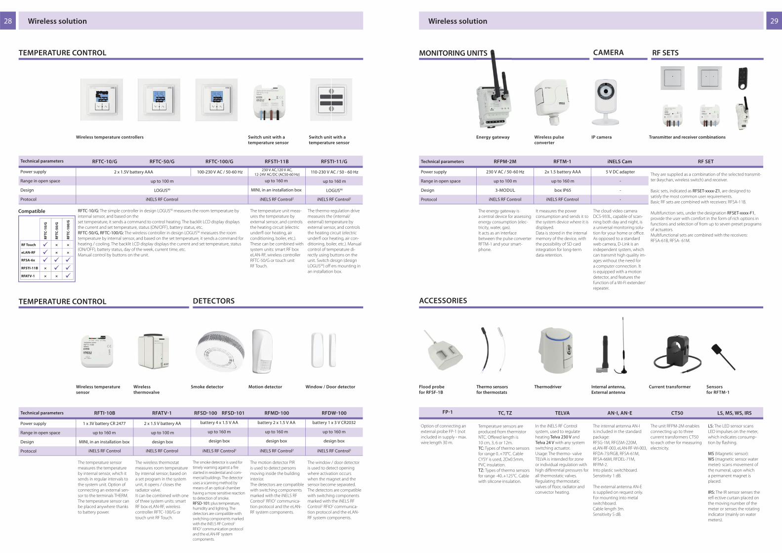
28 29
RFTC10/G RFTC50/G RFTC100/G RFSTI11B RFSTI11/G
iNELS RF Control iNELS RF Control2 iNELS RF Control2
RFTI10B RFATV1 RFSD100 RFSD101 RFMD100 RFDW100
iNELS RF Control iNELS RF Control iNELS RF Control2 iNELS RF Control2 iNELS RF Control2
× ×
× ×
× ×
×
RF
TC
-10
/G
RF
TC
-10
0/G
RF
TC
-50
/G
RF Touch
RFSA-6x
eLAN-RF
RFSTI-11B
RFATV-1
3
:3
:
RFPM2M RFTM1 iNELS Cam RF SET
iNELS RF Control iNELS RF Control
FP1 TC, TZ TELVA ANI, ANE CT50 LS, MS, WS, IRS
230 V AC,120 V AC,12-24V AC/DC (AC50-60 Hz)
Wireless solution Wireless solution
TEMPERATURE CONTROL
up to 160 m
MINI, in an installation box
Switch unit with a
temperature sensor
Switch unit with a
temperature sensor
Technical parameters
1 x 3V battery CR 2477
up to 160 m
MINI, in an installation box
Wireless temperature
sensor
The temperature unit meas-
ures the temperature by
external sensor, and controls
the heating circuit (electric
underfl oor heating, air
conditioning, boiler, etc.).
These can be combined with
system units: smart RF box
eLAN-RF, wireless controller
RFTC-50/G or touch unit
RF Touch.
The thermo-regulation drive
measures the (internal/
external) temperature by
external sensor, and controls
the heating circuit (electric
underfl oor heating, air con-
ditioning, boiler, etc.). Manual
control of temperature di-
rectly using buttons on the
unit. Switch design (design
LOGUS90) off ers mounting in
an installation box.
The temperature sensor
measures the temperature
by internal sensor, which it
sends in regular intervals to
the system unit. Option of
connecting an external sen-
sor to the terminals THERM.
The temperature sensor can
be placed anywhere thanks
to battery power.
2 x 1.5 V battery AA
up to 100 m
design box
Power supply
Range in open space
Design
Protocol
Wireless
thermovalve
Technical parameters
Wireless temperature controllers
2 x 1.5V battery AAA 100-230 V AC / 50-60 Hz
up to 100 m
LOGUS90
The wireless thermostat
measures room temperature
by internal sensor; based on
a set program in the system
unit, it opens / closes the
radiator valve.
It can be combined with one
of three system units: smart
RF box eLAN-RF, wireless
controller RFTC-100/G or
touch unit RF Touch.
RFTC-10/G: The simple controller in design LOGUS90 measures the room temperature by
internal sensor, and based on the
set temperature, it sends a command to control heating. The backlit LCD display displays
the current and set temperature, status (ON/OFF), battery status, etc.
RFTC-50/G, RFTC-100/G: The wireless controller in design LOGUS90 measures the room
temperature by internal sensor, and based on the set temperature, it sends a command for
heating / cooling. The backlit LCD display displays the current and set temperature, status
(ON/OFF), battery status, day of the week, current time, etc.
Manual control by buttons on the unit.
MONITORING UNITS
ACCESSORIES
Thermodriver
RF SETS
Internal antenna,
External antenna
In the iNELS RF Control
system, used to regulate
heating Telva 230 V and
Telva 24 V with any system
switching actuator.
Usage: The thermo- valve
TELVA is intended for zone
or individual regulation with
high diff erential pressures for
all thermostatic valves.
Regulating thermostatic
valves of fl oor, radiator and
convector heating.
The internal antenna AN-I
is included in the standard
package:
RFSG-1M, RFGSM-220M,
eLAN-RF-003, eLAN-RF-Wi-003,
RFDA-73/RGB, RFSA-61M,
RFSA-66M, RFDEL-71M,
RFPM-2.
Into plastic switchboard.
Sensitivity 1 dB.
The external antenna AN-E
is supplied on request only.
For mounting into metal
switchboard.
Cable length 3m.
Sensitivity 5 dB.
110-230 V AC / 50 - 60 Hz
up to 160 m
LOGUS90
Compatible
Power supply
Range in open space
Design
Protocol
TEMPERATURE CONTROL DETECTORS
Smoke detector
The smoke detector is used for
timely warning against a fi re
started in residential and com-
mercial buildings. The detector
uses a scanning method by
means of an optical chamber
having a more sensitive reaction
to detection of smoke.
RFSD-101: plus temperature,
humidity and lighting. The
detectors are compatible with
switching components marked
with the iNELS RF Control2
RFIO2 communication protocol
and the eLAN-RF system
components.
battery 4 x 1.5 V AA
up to 160 m
design box
battery 2 x 1.5 V AA
up to 160 m
design box
battery 1 x 3 V CR2032
up to 160 m
design box
Motion detector Window / Door detector
The motion detector PIR
is used to detect persons
moving inside the building
interior.
The detectors are compatible
with switching components
marked with the iNELS RF
Control2 RFIO2 communica-
tion protocol and the eLAN-
RF system components.
The window / door detector
is used to detect opening
where activation occurs
when the magnet and the
sensor become separated.
The detectors are compatible
with switching components
marked with the iNELS RF
Control2 RFIO2 communica-
tion protocol and the eLAN-
RF system components.
2x 1.5 battery AAA
up to 160 m
box IP65
Wireless pulse
converter
It measures the power
consumption and sends it to
the system device where it is
displayed.
Data is stored in the internal
memory of the device, with
the possibility of SD card
integration for long-term
data retention.
Energy gateway
230 V AC / 50-60 Hz
up to 100 m
3-MODUL
The energy gateway is
a central device for assessing
energy consumption (elec-
tricity, water, gas).
It acts as an interface
between the pulse converter
RFTM-1 and your smart-
phone.
Transmitter and receiver combinations
They are supplied as a combination of the selected transmit-
ter (keychan, wireless switch) and receiver.
Basic sets, indicated as RFSET-xxxx-Z1, are designed to
satisfy the most common user requirements.
Basic RF sets are combined with receivers: RFSA-11B.
Multifunction sets, under the designation RFSET-xxxx-F1,
provide the user with comfort in the form of rich options in
functions and selection of from up to seven preset programs
of actuators.
Multifunctional sets are combined with the receivers:
RFSA-61B, RFSA- 61M.
The unit RFPM-2M enables
connecting up to three
current transformers CT50
to each other for measuring
electricity.
LS: The LED sensor scans
LED impulses on the meter,
which indicates consump-
tion by fl ashing.
MS (Magnetic sensor):
WS (magnetic sensor water
meter): scans movement of
the numeral, upon which
a permanent magnet is
placed.
IRS: The IR sensor senses the
refl ective curtain placed on
the moving number of the
meter or senses the rotating
indicator (mainly on water
meters).
IP camera
The cloud video camera
DCS-933L, capable of scan-
ning both day and night, is
a universal monitoring solu-
tion for your home or offi ce.
As opposed to a standard
web camera, D-Link is an
independent system, which
can transmit high quality im-
ages without the need for
a computer connection. It
is equipped with a motion
detector, and features the
function of a Wi-Fi extender/
repeater.
5 V DC adapter
-
-
-
Power supply
Range in open space
Design
Protocol
Option of connecting an
external probe FP-1 (not
included in supply - max.
wire length 30 m.
Technical parameters
Flood probe
for RFSF-1B
Current transformer Sensors
for RFTM1
CAMERA
Thermo sensors
for thermostats
Temperature sensors are
produced from thermistor
NTC. Off ered length is
10 cm, 3, 6 or 12m.
TC: Types of thermo sensors
for range 0..+70°C. Cable
CYSY is used, 2Dx0.5mm,
PVC insulation.
TZ: Types of thermo sensors
for range -40..+125°C. Cable
with silicone insulation.

30
RFSAI161B RFSTI111B RFTC150/G RFSA166M
iNELS RF Control2 iNELS RF Control2 iNELS RF Control iNELS RF Control2
3
:
110-230 V AC/50-60 Hz, 12-24V AC/DC SELV
230 V AC, 120 V AC,12-24V AC/DC (AC 50-60 Hz)
230 V AC, 120 V AC,12-24V AC/DC (AC 50-60 Hz)
RFPCR31/G RFGCR31 RFGCH31 21031 & 90731
Wireless solution
www.inels.com
AC 230 V
up to 100 m
LOGUS90
AC 230 V
up to 100 m
glass design
AC 230 V
up to 100 m
glass design
AC 230 V
-
LOGUS90
After inserting hotel card to card
switches it will activate automatic
regulation of the lights in the room.
ACCESS CONTROL
Multifunctional
in front of Controller
Multifunctional
in front of Controller
Card Switch Card Holder
Power supply
Range in open space
Design
Protocol
Technical parameters
Power supply
Range in open space
Design
Technical parameters
Automatic light control Overheating
protection of room
Temperature control Wireless switch unit
up to 160 m
MINI, in an installation box
Temperature component with
one output channel serves as
protection against overheating of
the room, where the infl uence of
temperature can cause damage
to furniture and appliances. It is
particularly suitable for rooms with
a tropical climate.
The wireless controller RFTC-150/G
in design LOGUS90 measures the
room temperature by internal sen-
sor. On the basis of a set program it
sends commands to the switching
component RFSA-166M Switching
fan coil.
battery 2 x 1.5 V AAA
up to 100 m
LOGUS90
up to 160 m
MINI, in an installation box
Thanks to the 6-channel design
of the switching component it
can control the heating / cooling
mode and 3 speeds. The RFWD-100
detector can be paired with RFSA-
166M via the fi rst relay contact.
The package includes an internal
antenna AN-I, in case of locating
the element in a metal switch-
board, you can use the external
antenna AN-E for better signal
reception.
up to 100 m
3-MODUL
LIGHTING TEMPERATURE
Switch component with one
output channel which is used in
combination with detectors for
automatic lighting control. Thanks
to its unique functionality it is espe-
cially suited for hotels.
Multifunctional in front of control-
ler included: RFID card reader, bell
button, “Do Not Disturb” and “Make
Up Room” signalling. Available in
LOGUS90. Communication: wireless
868 MHz (iNELS RF).
Multifunctional in front of control-
ler included: RFID card reader, bell
button, “Do Not Disturb” and “Make
Up Room” signalling. Available in
glass design in white (RFGCR-31 /
W) or black (RFGCR-31 / B) colour.
Communication: wireless 868 MHz
(iNELS RF).
Card holder with RFID reader.
Allows detect fake card “Do Not
Disturb”, “Make Up Room” signalling
“Master OFF” button. Available in
glass design in white (RFGCH-
-31/W) or black (RFGCH-31/B)
colour.
www.inels.com
Wired electro-installationSmart home & building solution
NEWNEW

32 33
CU301M CU302M CU303M
PS3-100/iNELS MI3-02M MI3-02/iNELS2 BPS301M BPS302M GSM3-01M
2x BUS iNELS3 2x BUS iNELS2
BUS 27 V DC
1x BUS 2x BUS
BUS 27 V DC
-
BUS 27 V DC
27.6 V/3.6 A, 12.2 V/0.35 A
100 - 250 V AC
-
BUS solution BUS solution
External master
bus
Power supply
SYSTEM UNITS
Is a stabilized switching
power supply, with the total
power of 100 W.
Power supply:
100 - 250 V AC.
Output voltage: DC/max.
load: 27.6 V / 3.6 A and 12.2 V
/ 0.35A, 6-MODULE.
Central units CU3-01M, CU3-02M and CU3-03M are the brain of the iNELS BUS system, a "mediator“ between user‘s programming environment and
controllers, units and actuators connected to the bus.
Central unit
• CU3-01M and CU3-02M are central units’ of the iNELS system and mediators, between user software interface and control-
lers, units and actuators connected to the BUS.
• It‘s possible to directly connect up to 2 lines of BUSes in to CU3-01M and CU3-02M, and on each BUS we can connect up to
32 iNELS3 units.
• The main diff erence between CU3-02M and CU3-01M is that CU3-02M is moreover equipped by RF module which enables
communication with selected units from iNELS RF Control system.
• Central units CU-01M (02M) support also peripheral units from iNELS2 thanks to external master MI3-02M/iNELS2.
• User´s project and retentive data are stored in a non-volatile internal memory hereby data are backed up without the sup-
ply voltage. Real time clock (RTC) backup for 10 days.
• Power supply controlling system - network voltage and the status of the backup battery.
• Possibility of setting time synchronization via NTP server.
• The RJ45 Ethernet port‘s connector is located on the front panel of the unit, the transmission speed is 100 Mbps.
• For CU3-01M (02M) it is possible to use 4 potential-free inputs for connecting external controllers (buttons, switches, sen-
sors, detectors, etc.) and 2 analog inputs 0 - 30V.
• CU3-01M (02M) comes with OLED display that shows the current status and enables settings (network settings, date, time,
service) of the central unit CU3-01M (02M).
• Movement in the menu CU3-01M (02M) using arrows on the front panel.
• CU3-01M (02M) in 6-MODULE are designed for mounting into a switchboard on the EN60715 DIN rail.
GSM communicatorBus separator for separation
from power supply
Technical parameters
Output
Power supply
Rated current
• CU3-03M is a new, enhanced version of CU3-01M and
CU3-02M.
• The new HW equipment allows communication with the
DALI bus to connect up to 64 electronic ballasts (the inter-
nal power supply of the CU3-03M is capable of supplying
connected ballasts up to a nominal value of 64 mA).
• RF Communication Interface for Controlling Wireless
Receivers iNELS RF Control (the current list of supported
receivers is available in the iNELS Installation Guide).
• The CU3-03M is equipped with three Ethernet ports, one
for Ethernet (100 Mbps) connections and two for CU3-03M
controllers.
• The CU3-03M has a TFT display that shows the current
status and allows some basic unit parameters such as
network setup, date, time, or service.
• The movement in the CU3-03M menu is possible by using
the directional buttons on the front panel.
25 mA (at 27 V DC) 250 mA (at 27 V DC) / max. 1A8 mA (at 27 V DC) 15 mA (at 27 V DC)
External master MI3-02M provides expansi-
on of the amount of units iNELS3 connected
to the central unit CU3-01M or CU3-02M
of two other lines of BUS (i.e. about 2x32
peripheral units).
If you require the use of a central unit CU3-
-01M (02M) in combination with the iNELS2
units, all the units must be connected to the
BUS lines, which are based on an external
master MI3-02M/iNELS2.
Units BPS3-01M and BPS3-02M serve for
impedance separation of BUS from supply
voltage power.
BPS3-01M allows you to connect one BUS
with max. load 3 A.
BPS3-02M allows you to connect two
separate BUS1 and BUS2 with max. load 1 A
for each line.
1-MODUL.
It serves for communication
with the iNELS system via
commands sent in short
SMS messages from mobile
phone GSM. GSM3-01M con-
nects to the central unit CU3
via the EBM
system BUS.
3-MODULE.
What are the benefi ts of BUS controlling?
• Save energy by regulating lighting and heating properly
• Control of blinds, awnings, exterior or internal window
shutters
• Dimming lights, lighting scenes
• control of appliances or electrical devices
• Control access gates, garage doors
• Logical and central functions (exit button, ...)
• Manual and automatic control mode
• Preventing undesirable opening of a window or a door
• Responding to the movement of people
(authorized and unauthorized)
• Remote monitoring via smartphone, tablet or laptop
• Possibility to control via the iNELS Touch Panel 10"
• Integration of third-party devices (cameras, air conditioning, ...)
The BUS electro installation iNELS BUS System is a unique solution for
electrical installation in the implementation of new projects of houses,
villas, apartment buildings, offi ce buildings, hotels, restaurants, well-
ness centres or perhaps even warehouse or production hall.
The ability to deploy this solution in such a wide variety of diff er-
ent buildings with various purposes and uses lies in its modularity.
Thanks to the modular design, the system is very fl exible and allows
on the one hand, a solution of single-purpose tasks such as control
of lighting in restaurants, and on the other hand, solving complex
control systems for heating, ventilation, cooling, lighting and shad-
ing of offi ce buildings. A complete range of control units designed
from glass for management of hotel rooms is in the market unique.
Thanks to its modularity is very easy to customize the size of the
system and to that eff ect create a cost eff ective solution.
Smart homes and buildings are accompanied by three basic ideas,
namely savings, comfort and safety, the fi rst two ideas may at fi rst
glance contradict each other. However, the main objective of smart
home or building equipped with the iNELS solution is to attain the
optimum indoor environment while achieving the most effi cient op-
eration of all system.
In homes and buildings the optimal internal environment is very im-
portant because people nowadays spend up to 80 % of their time
inside buildings. It is also shown that indoor environments, where we
talk about thermal comfort, lighting comfort and indoor air quality
signifi cantly aff ect the mood and the eff ectiveness of people.
The iNELS system allows connection of wide range of sensors (tem-
perature, light intensity, carbon dioxide, humidity, and pressure) and
detectors (movement, opening doors and windows, gas leakage,
smoke, fl ooding) whose values are constantly evaluated. At the same
time iNELS allows the connection of all the technologies that are
installed in the building, which continued to signifi cantly increase
operational effi ciency or comfort, for example; in the case of inte-
grating the guest room management system with the receptionist
Fidelio system, which automatically during check-in, sends the room
requests for execution, a welcome scene (optimum temperature,
comfortable lighting scene, music etc.).
More systems can be controlled by iNELS:
Wall controller Key Fob Remote control
Touch panel Smartphone iTP – iNELS Touch panel
NEW

34 35
SA301B SA302B SA302M SA304M SA3-06M
SA3012M SA3022M JA302B/DC JA309M FA3-66M IM320B IM340B IM3-80B IM3-140M TI310B TI340B TI3-60M
DA306M DA3-22M LBC3-02M DCDA-33M EMDC64M
BUS solution BUS solution
Switching actuator,
12-channel
Shutter actuator
Universal dimming
actuator, 2-channel
SWITCHING ACTUATORS
Number of contacts
Switching current
Switching output
Power supply
Rated current from BUS
4 x changeover
16 A / AC1
4000 VA / AC1, 384 W/DC
BUS 27 V DC
70 mA (at 27 V DC)
6 x changeover
8 A / AC1
2000 VA / AC1, 192 W/DC
BUS 27 V DC
60 mA (at 27 V DC)
2 x changeover
16 A / AC1
4000VA / AC1, 384W/DC
BUS 27 V DC
50 mA (at 27 V DC)
The actuator is designed for
switching up to two various
appliances and loads relay
output (potentialless con-
tact). Thanks to changeover
contacts, it can be used to
control one 230 V power
(such as blinds, shutters or
awnings).
1-MODUL
The actuator is designed
for switching to four
various appliances and loads
relay output (potential free
contact). LEDs on the front
panel signal the status of
each output.
3-MODUL
The actuator is suitable for
operating discontinuously
controlled thermo drives
in the distributor underfl
oor heating. The relays are
divided into two groups, the
group of four relays on the
bottom terminal switches
the common potential,
a pair of relays on top of the
terminal switches second
common potential.
3-MODUL
12x NO
8 A / AC1
2000 VA / AC1, 192 W/DC
BUS 27 V DC + 230 V AC (120 V AC)
5 mA (at 27 V DC)
SA3-012M is a switching
actuator containing 12
independent relays with NO
potentialless contacts, with
the fact that switches the
same potential. The actuator
is powered via BUS and
simultaneously by an AC
voltage:
SA3-012M - 230V AC,
SA3-012M/120V - 120V AC.
6-MODULE.
1 x NO
16 A / AC1
4000 VA
BUS 27 V DC
30 mA (at 27 V DC)
Actuators are designed for switching of one (SA3-01B),
respectively two (SA3-02B) of various appliances and loads
relay output (potentialless contact).
Actuators are equipped with a temperature input for con-
necting an external two-wire temperature sensor TC / TZ.
Mounting into an installation box.
Number of contacts
Switching current
Switching output
Power supply
Rated current from BUS
2x MOSFET
2 x button, 1 x temperature
BUS 27 V DC+230 V AC(120 V AC)
5 mA (at 27 V DC)
Universal dimming two-
channel actuator for dim-
ming ESL, LED and RLC loads,
2x 400 VA, 2x controlling
input, 1x temperature input
TC/TZ. The actuator is pow-
ered via BUS and simultane-
ously by an AC voltage:
DA3-22M - 230V AC,
DA3-22M/120V - 120V AC.
3-MODULE.
* Maximum output time with
rated current of 0.85A is for
10 min.
Technical parameters
Technical parameters
actuator serves to control
blinds, shutters, garage
doors, entrance gates, etc.
The unit is also equipped
with two analog digital
inputs (AIN/DIN), which can
be used to connect two
potential free contacts or
a single external temperature
sensor TC/TZ.
Mounting into an installation
box.
1x 12 - 24 V DC
0.85 A*
-
BUS 27 V DC
60 mA (at 27 V DC)
2x changeover
8 A / AC1
2000 VA
BUS 27 V DC
50 mA (at 27 V DC)
Switching actuator,
1-chanel
Switching actuator,
2-channel
Switching actuator,
4-channel
Switching actuator,
6-channel
SWITCHING ACTUATORS
22x (NO / changeover)
according to output (6A / 10A)
according to output
BUS 27 V DC
100 mA (at 27 V DC)
Switching actuator,
22-channel
SA3-022M is an expansion
module for the CU3-03M
central unit, designed
primarily for controlling
the hotel room.
6-MODULE.
Roller Shutter Actuator,
9-channel
JA3-09M is an actuator
designed for control of roller
shutters, blinds, awnings,
garage doors, entrance
gates, etc.
The actuator is powered via
BUS and simultaneously by
an AC voltage:
JA3-09M - 230V AC,
JA3-09M/120V - 120V AC.
6-MODULE
9x changeover
4 A/AC15
1000VA/ AC 15, 100 W/DC
BUS 27V DC + 230 V AC (120 V AC)
5 mA (at 27 V DC)
-
BUS 27 V DC+230 V AC (120 V AC)
5 mA (at 27 V DC)
DA3-06M is a universal
six-channel dimmer actuator
that controls the brightness
of dimmable ESL, LED and
RLC light sources with 230V
power.
The actuator is powered via
BUS and simultaneously by
an AC voltage:
DA3-06M - 230V AC,
DA3-06M/120V - 120V AC.
6-MODULE.
Dimming actuator,
6-channel
6x contactless outputs, 2x MOSFET
Fan Coil Control Actuator
4x (0)-10V, 8x Re
3x analog, 3x digital
according to output
BUS 27 V DC
5 mA (at 27 V DC)
FA3-66M is a unit (actuator)
designed to control fan coil
units using analogue / digital
inputs and analog / relay
outputs.
6-MODULE
Binary input unitBinary input unit Temperature input,
6-channel
The binary input unit is
designed to connect up to
14 devices with potential
free contact (PIR, button,
etc.), 14x binary input, output
for power supply detectors
12 V DC/150 mA.
3-MODULE
For connecting 1x/4x
temperature sensor TC, TZ,
Ni1000, Pt1000 or Pt100.
Mounting into an installation
box.
Number of inputs
Temperature sensors
Power supply
Rated current from BUS
Binary input units are used
for connection of 2 or 4
devices with potential-less
contacts (PIR, button, etc.),
1x temperature input TC/
TZ, output for power supply
detectors 12 V DC/75 mA.
Mounting into an installation
box.
8x binary
1x TC/TZ
BUS 27 V DC
20 mA (at 27 V DC)
For connecting 6x tempera-
ture sensor TC, TZ, Ni1000,
Pt1000 or Pt100.
3-MODULE.
2x binary 14x binary
-
BUS 27 V DC
25 mA (at 27 V DC)
1x temper. 6x temperature
TC, TZ, Ni1000, Pt1000, Pt100
BUS 27 V DC
45 mA (at 27 V DC)
Binary input units are used
for connection of 8 devices
with potential-less contacts
(PIR, button, etc.), 1x temper-
ature input TC/ TZ, output for
power supply detectors 12 V
DC/75 mA.
Mounting into an installa-
tion box.
Binary input unit
Technical parameters
Technical parameters
4x temper.
Temperature input,
1-channel and 4-channel
4x binary
THERMO INPUT
DIMMING ACTUATORS
Dimming actuator,
3-channel
Dimming actuator is de-
signed for dimming RGB
and LED light sources with
power supply 12-24 V DC,
which are controlled by
variable current. Controlling
interface DMX, DALI and
BUS. 3 channels, max. 2A on
one channel.
3-MODULE.
3x MOSFET
-
BUS 27 V DC + 12-60 V
40 mA (at 27 V DC)
1x TC/TZ
BUS 27 V DC
20 mA (at 27 V DC)
TC, TZ, Ni1000, Pt1000, Pt100
BUS 27 V DC
20 mA (at 27 V DC)
Dimming actuator for
electronic ballasts,
2-channel
-
BUS 27 V DC
60 mA (at 27 V DC)
Analog two-channel actua-
tor for controlling dimmable
electronic ballasts, 2x analog
signal 1-10V, 2x switching
contact 16 A, LED indicator
of relay status.
3-MODULE.
2x 0(1)-10V / 10 mA,2x changeover 16 A/AC1
Gateway
iNELS - DALI/DMX
The unit EMDC-64M is
designed to control DALI
electronic ballasts and
DMX receivers from the
iNELS system. EMDC-64M
enables control of up to
64 independent electronic
ballasts DALI (Digital Ad-
dressable Lighting Interface)
for fl uorescent lamps, LEDs
and other light sources.
3-MODULE.
DALI (64 ch) / DMX (32 ch)
-
AC 230 V (max. 100 mA)
DALI power supply: 16 V, 250 mA
Switching actuator,
2-chanel
Output
Input
Power supply
Rated current from BUS
NEW NEWNEW
NEW

3736
ADC360M DAC304B DAC304M WSB320, WSB320H WSB340, WSB340H
EST3 GSB340, GSB360, GSB380 IDRT31 WMR321 GMR3-61 GSB3-20/S GSB3-40/S GSB360/S GSP3100
CU3-04M GCR311 GDB3-10
BUS solution
Control unit with
touch screen
Wall card readerDigital room
thermo-regulator
Number buttons
Power supply
Rated current from BUS
Internal temp. sensor
External temp. sensor
-
2 x DIN / 1x temperature
BUS 27 V DC
25 mA (at 27 V DC)
max. 12
BUS 27 V DC
150 mA (at 27 V DC)
-
-
2
BUS 27 V DC
50 mA (at 27 V DC)
-
-
2 (for correction temper.)
BUS 27 V DC
20 mA (at 27 V DC)
YES
YES
-
2 x DIN / 1x temperature
BUS 27 V DC
25 mA (at 27 V DC)
EST3 features a 3.5 "color
touchscreen with an aspect
ratio of 3:4. For screen of
buttons one of four diff erent
matrixes buttons can be
used - 2x2, 2x3, 3x3 and 3x4.
LOGUS90 design.
Wall controller, 2x button,
built-in temperature and
humidity sensor (H version),
1x LED display.
LOGUS90 design.
WMR3-21 is a wall-mounted
card reader that is designed
for read contactless media
(smart cards, key chains, etc.),
which are used for control-
ling access to buildings or
their parts.
LOGUS90 design.
Control unit for correction
of circuit of heating/ cooling
±5 °C or for direct entering of
the required temperature in
°C, built-in temperature
sensor.
LOGUS90 design.
Wall controller, 4x button,
built-in temperature and
humidity sensor (H version),
1x LED display.
LOGUS90 design.
6
BUS 27 V DC
50 mA (at 27V DC)
YES
-
Wall RFID card reader GMR3-
61 is designed for reading
of contactless media (chip
cards, key fobs, tags, etc.),
which are used for control-
ling access to buildings or
parts of buildings. Is available
in black (GMR3-61/B) and
white (GMR3-61/W) variants.
Glass wall card
reader
Wall group controllers
with low-upstroke
control
Wall group controllers
with low-upstroke
control
Technical parameters
Technical parameters
WALL UNITS AND CONTROLLERS
4 6 8
BUS 27 V DC
25-40 mA (at 27 V DC)
YES
YES
The wall controller with
touch controls series GSB3 is
a design element (controller)
in the system iNELS with
elegant and comfortable
control. Controllers are avail-
able in black (e.g. GSB3-40/B)
and white (e.g. GSB3-40/W)
variants.
Glass wall touch
controllers
WALL UNITS AND CONTROLLERS
Glass touch controllers with symbols
Glass card reader
Glass bedside panel
Number buttons
Power supply
Rated current from BUS
Temperature measurement
Glass RFID card reader GCR3-
11 is part of a comprehensive
range of glass iNELS control
units and can be advanta-
geously used in all projects,
e.g. guest room manage-
ment system (GRMS), is
available in elegant black
(GCR3-11/B) and white
(GCR3-11/ W) variants.
2
BUS 27 V DC
25-35 mA (at 27 V DC)
internal, 1x external TC/TZ
BUS 27 V DC
100-130 mA (at 27 V DC)
3
-
4
BUS 27 V DC
25-43 mA (at 27 V DC)
internal, 1x external TC/TZ
6
BUS 27 V DC
25-50 mA (at 27 V DC)
internal, 1x external TC/TZ
GSB3-20/S is equipped with two, GSB3-40/S with four and GSB3-60/S six touch buttons
whose functions can easily modify by the software.
Printing is possible to customize to the investor requirements.
Individual symbols can be illuminated in one of seven colours - red, green, blue, yellow,
pink, turquoise and white.
Glass touch panel is a design component of the iNELS system and is available in elegant
black (GSB3-20/SB, GSB3-40/SB, GSB3-60/SB) and white (GSB3-20/SW, GSB3-40/SW, GSB3-
60/SW) versions.
All versions are in the size of the module (94x94 mm).
Central unit
BUS 27 V DC
110 mA (at 27 V DC)
5
-
CU3-04M is equipped with:
- Digital input for connecting push-button controls, motion detectors or, for example
magnetic detectors.
- Analog inputs for connecting temperature sensors.
- Digital outputs for the control of actuators, ventilator fan coil units, door locks, lighting,
shading techniques, sockets and other equipment.
- Analog output 0(1) -10V for controlling actuators and controlled continuously dimmable
ballasts, controlled using voltage signals.
- Installation BUS for connecting up to 32 BUS controllers and thermostats.
- One DALI BUS for up to 64 electronic ballasts illumination (internal source CU3-04M is able
to power the connected ballasts up to a nominal value of 64 mA).
- RF communication interface for controlling iNELS RF Control wireless receivers (updated
list of supported receiver is available in the iNELS installation manual).
Power supply
Rated current from BUS
Number buttons
Temperature measurement
Technical parameters
Technical parameters
10
BUS 27 V DC
25-65 mA (at 27 V DC)
internal, 1x external TC/TZ
GSP3-100 is equipped with ten touch buttons whose func-
tions can easily be edited using the software.
The graphics of individual symbols are possible based on
consultations with manufacturers to change and adapt to
the requirements of the investor.
Individual symbols can be any one of seven backlight co-
lours - red, green, blue, yellow, pink, turquoise and white.
Glass touch panel is a design component of the INELS sys-
tem and is available in elegant black (GSP3-100/B) and white
(GSP3-100/W) versions.
Compared with standard glass touchscreen controllers with
symbols GSB3 the GSP3-100 is one and a half times the
width.
BUS 27 V DC
100-120 mA (at 27 V DC)
1
internal, 1x external TC/TZ
Glass info panel GDB3-10
is part of a comprehensive
series of glass iNELS control
units for guest room man-
agement system (GRMS), and
is used to indicate the status
of guest requests
"Do Not Disturb" and "Make
Up Room" and is available in
elegant black (GDB3-10/B)
and white (GDB3-10/W)
version.
Glass info panel
Hospitality solution
HOSPITALITY SOLUTION
HOSPITALITY SOLUTION
Analog-digital
converter
Digital-analog
converter
Digital-analog
converter
4 x 0(1) - 10 V / 10 mA
1 x temperature
BUS 27 V DC
50 mA (at 27 V DC)
4 x 0(1) - 10 V / 10 mA
1 x temperature
BUS 27 V DC
50 mA (at 27 V DC)
-
6 x analog.; 0-10 V; 0-20 mA
BUS 27 V DC
100 mA (at 27 V DC)
Is a converter of a digital
signal to an analog voltage
signal. 0(1)-10 V, for control
of electronic ballasts, thermal
actuators, etc., 4 channels, 1x
temperature input TC/ TZ.
Mounting into an installation
box.
Is a converter of a digital
signal to an analog voltage
signal. 0(1)-10 V, for control
of electronic ballasts, thermal
actuators, etc., 4 channels, 1x
temperature input TC/TZ.
3-MODULE.
Converter of analog signals
on bus (e.g. for connecting
a weather station), 4x analog
input, 2x temperature input
TC, TZ, Ni1000, Pt1000 or
Pt100.
3-MODULE.
CONVERTERS
Output
Input
Power supply
Rated current from BUS
NEW

38 39
GBP360R GBP360L
GBP3 - 6 0 /x x /xF -x-x
GBP3-60/WL/2F-26W-20W
GBP3-60/WL/1F-21W45W
GBP3-60/BR/2F-26B-11B44B
GBP3-60/BR/1F-26B
1 / 2
EHT3 GRT350 GCH331
BBC
15. 9. 2015 11:30
ACTUAL
24
20SETTING
DMD3-1 DLS3-1 TC, TZ, Pt100 TELVA ANII, ANE
HOSPITALITY SOLUTION
The GBP3-60 is available in several designs, making it a very
fl exible and eff ective solution for a variety of projects. The
following variants are available:
- Left / Right version provides the same ease of operation
from both sides of the bed.
- 2-module / 3-module design enables you to add a touch
module with one or two power supply modules, network
connection or multimedia.
- Black / White elegant design suitable for almost any interior.
GBP3-60 can be equipped with a number of modules, for
example.
- Power AC sockets: French, British, Multi, and Shockproof
- Other types of modules: USB, LAN, Media
Technical parameters
Number buttons
Power supply
Rated current from BUS
Temperature measurement
6
BUS 27 V DC
25-50 mA (at 27 V DC)
1x external TC/TZ
Glass bedside panel
- right option
Glass bedside panel
- left option
Hospitality solution
L (left option) R (right option)
position 2 position 2position 1 position 1
position 1position 1
Confi gure bedside panel according to your request.
Part number
L / R
(left / right)
our product
code(s)*
our product
code(s)*
B / W
(black / white)
Glass
button
panel
iNELS3
6 buttons
* In case of 1-module choice it is necessary to pick 2x 1-module to fi ll up the 1 position, for example GBP3-60/WL-21W45W.
position 2position 1typecolor number of frame
Variants
HOSPITALITY SOLUTION
ACCESSORIES
Multifunctional Touch Control Unit
Touch screen
BUS 27 V DC
150 mA (at 27 V DC)
-
3
BUS 27 V DC
100-120 mA (at 27 V DC)
-
EHT3 features a 3.5 "color touchscreen with an
aspect ratio of 3:4. For screen of buttons one of
four diff erent matrixes buttons can be used
- 2x2, 2x3, 3x3 and 3x4.
LOGUS90 design.
GCH3-31 serves for inserting the RFID card into
the holder, whereby the system acquires the
information about whether the hotel guest is
present in the room. With this information it is
possible to ensure for example Exit function with
relation to energy savings in the absence of
a guest in the room.
Technical parameters
Number buttons
Power supply
Rated current from BUS
Temperature measurement
5 + 2
BUS 27 V DC
85 mA (at 27 V DC)
internal, 1x external TC/TZ
Glass room thermo-regulator GRT3-50 is part of
a comprehensive range of glass iNELS control
units for guest room management system (GRMS)
and serves to regulate the temperature in the
room.
Glass room thermo-regulator Glass card holder
Hospitality solution
Combined detector Luminescence sensor
The motion detector is used
to detect people moving in
the area. Using the passive
scanning infrared spectrum
for detection. Integrated
luminescence sensor can
be used for sensing current
luminescence at the point of
installation of the unit.
BUS 27 V DC
18 mA (at 27 V DC)
16 V (max. 23 V)
The luminescence sensor
DLS3-1 is for sensing the
current luminescence at
the point of installation of
the unit. The DLS3-1 unit is
supplied in IP65 and so can
be installed in the outdoor
environment.
BUS 27 V DC
12 mA (at 27 V DC)
16 V (max. 23 V)
DETECTORS
Power supply
Rated current from BUS
DALI power supply
Technical parameters
Internal antenna,
External antenna
The internal antenna AN-I
is included in the standard
package.
Into plastic switchboard.
Sensitivity 1 dB.
The external antenna AN-E
is supplied on request only.
For mounting into metal
switchboard.
Cable length 3m.
Sensitivity 5 dB.
Thermo sensors
for thermostats
TC: Types of thermo sensors
for range 0..+70°C. Cable
CYSY is used, 2Dx0.5mm, PVC
insulation
TZ: Types of thermo sensors
for range -40..+125°C. Cable
with silicone insulation.
Pt100: Types of thermo
sensors for range -30..+200°C.
shielded cable with silicon
insulation 2x0.22 mm2.
Temperature sensors are pro-
duced from thermistor NTC.
TC, TZ, Pt - off ered length is
10 cm, 3, 6 or 12m.
Thermo-valve
Thermodriver Telva is a suit-
able control unit for a wide
range of thermostatic valves.
Visual indicator of valve
position.
Design:
NO - without voltage open
NC - without voltage closed
Types of thermo actuators:
- TELVA 230V, NO
- TELVA 230V, NC
- TELVA 24V, NO
- TELVA 24V, NC.

40
О x
Android iOS Android iOS
iPad iPhone iPhone
iHC-TA iHC-MA iHC-TI iHC-MI TIZEN 3.0 iHC-MAIRF iHC-MIIRF eLAN-RF
x x
x x x x
x
x x
x x x x
x x x x
x x
О О x x
x x
x x
BU
S &
RF
Smart TV Smart watch
iHC-WTRF
ROOMS SCENESCAMERA
/
Samsung Hospitality TV
MULTIMEDIAiNELS Home Control applications are FREE to download at or
and are supported by Android OS 2.3 or later and iOS
www.inels.com
Coming soonSupported Not supported
iNELS BUS System(bus electro installation)
iNELS RF Control(wireless electro installation)
Lighting
Blinds
Socket
Garage doors,
gates
RGB bulbs,
LED strips
Scenes
Heating
Multimedia
Cameras
Air-conditioning
Recuperation
Home appliances
(MIELE)
Weather station
Measurement and
visualization of energy
Door communicator
and Intercom
Th
ird
Pa
rite
s In
teg
rati
on
The list of supported third-party systems is available on our web page www.inels.com
Applications
A/V appliances
PhoneTablet Phone
www.inels.com
MultimediaSmart home & building solutions

42 43
iTP 10" eLANIR003
iMM Audio Zone-R Connection Server
LARA RADIO LARA INTERCOM
Wi-Fi
(75021)
AC 230
(67
01
)
(21581 + 90710 TBR + 90910 TBR)
01.01.2013 12:54STATION:
RadioNOW PLAYING:
Radio
PLAYING ...
MP3128
01.01.2013 12:54STATION:
RadioNOW PLAYING:
Radio
PLAYING ...
MP3128
AdeleDLNAAdele
... Hello
10.8.2018 12:54
• 10" touch panel designed to control iNELS.
• Black aluminum frame chassis in combination with glass.
• Integrated speakers and microphone are primarily designed for intercom operation.
• Connection to the local area network can be done with Ethernet connection with PoE
power supply - Active Poe (IEEE 802.3af).
• Android for iHC (iNELS Home Control) applications or Future offi ce applications.
• Update applications over the Internet.
• Active PoE power.
• The panel also includes a cover that also serves as a mounting frame.
• The connection server is providing a communication environment between iNELS BUS
System with the third party devices, for which their protocols are also translated and sub-
mitted.
• The iHC appliction‘s environment enables us to control all these technologies from just
one app.
• The inclusion Connection Server to the system can be controlled from the application iHC
except BUS units (lighting, blinds, heating, etc.) also IP cameras, air conditioning, recupera-
tion or domestic appliances Miele.
• It also allows the communication with the domestic voice intercom 2N. It can also arrange
the information from the weather station Giom or data from energy meters (electricity,
water, gas), which is visualized in clear graphs.
• The device connection server uses the Raspberry Pi hardware and the apps requires
a license relative to the MAC address of the device.
• While connecting with the devices connection server, it‘s recommended to use an unin-
terruptible power supply (UPS), which ensures that, there will be no power outage.
• As a part of the package, we also included an SD card where we previously installed Linux
OS on it and its needed software equipment.
• The confi guratution is happening on its own web interface, where the default IP address
is not fi xed. (The IP address is assigned from the DHCP server and it‘s needed to be known
when we‘re connected to the network).
• The iMM Audio zone-R serves as a player for the other Audio zones where we also can
integrate the iMM server to the iNELS system.
• The iMM Audio zone-R allows us to play music which is stored on the network storge,
which by itself could be an NAS (Network Attached Storage), for example: Synology.
• The music is being played through the Logitech Media Server.
• We can control every iMM Audio zone-R in the system using the iHC application in any
smart phone or a tablet, possibly from the iMM application TV picture (Video zone).
• The Audio zone is equipped with a stereo jack of 3.5mm output for supplying to the am-
plifi er or active speakers.
• The Audio zone can be connected via an HDMI to a TV or a monitor with speakers and play
music within these devices.
• An HDMI output for the connection of the monitor to determine the IP address service
(see the instructions).
• 2x USB ports, for example for connecting a keyboard during the IP address determination
process.
• 1x RJ45 for the connection to the computer or to an Ethernet Network.
• The confi guration is done on their own web interface with the default IP address
192.168.1.220
• As a part of the package, we also included an SD card where we previously installed Linux
OS on it and its needed software equipment.
• The applications iHC-MAIR and iHC-MIIR provide universal control for all Audio/Video de-
vices (including air conditioning).
• The application is connected via smart phone connected to the smart IR box eLAN-IR-003,
which communicates with Audio/Video devices via IR sensor.
• The intuitive application environment makes it simple for anyone to control.
• What all can you control? home theater, TV, DVD or Blue Ray player, amplifi er, set-top box,
satellite receiver, air-conditioning, projector and more...
• It can control up to 100 arbitrary commands with various controllers that you normally
have at home.
• The scenes function, where, you perform multiple functions simultaneously by a single
command (e.g. you are going to bed you and switch off all AV appliances in the entire
home with a single press).
• It is possible to integrate into a single application an unlimited number of IR boxes, mean-
ing that in one application, you have control over the living room, children‘s rooms, etc.
• It is also possible to control remotely from anywhere using a Wi-Fi network (e.g. from work
or vacation).
• Thanks to auto-IP acquisition from the DHCP server, you need not set up a network (if you
have no set fi xed IP address).
• You can connect three sensors to the smart IR box eLAN-IR-003 for three directions of
control.
Multimedia
Multimedia
Multimedia
iNELS Touch Panel 10" Smart IR box
• LARA Intercom off ers users 5 diff erent functions and expands even more
options to Lara Radio - music players and internet radio stations within the
range of LOGUS90 switch designs.
• LARA Intercom provides an extra functionality and videophone intercom.
• Thanks to videophone function, now it is possible to have a voice commu-
nication between LARA and the sound of the door (IP Intercom), so with
someone visiting and standing in front of the house, we can see that on
LARA display as part of this function which increases the security feeling
and safety besides of course, the comfort for the user.
• LARA Intercom is equipped with an OLED colored display with the size of
1.5“, which is used to transfer images and sounds from the door camera
properly.
• A music and Internet radio player - all in the dimension of a switch and
a luxurious LOGUS90 design.
• LARA Radio - when connected to the Internet, it can play streaming radio
stations and you can store up to 40 of them. But you can also select from
thousands of radio stations from across the globe, which provide data for
correct connection.
• LARA Radio can play content from an external music source, which can
be an smart phone or e.g. an MP3 player. These devices are connected to
a 3.5mm stereo jack audio input, located underneath the front panel.
• LARA Radio can also play audio fi les from central data storage, onto which
Logitech Media Server is installed.
POE 24 V DC/1.25 A
1.4 W / 26 W (peak at maximum playback performance)
Color OLED, Resolution: 128 x 128 pixels
no
Power supply
Min. /max. input
Display
Microphone
POE 24 V DC/1.25 A
1.4 W / 26 W (peak at maximum playback performance)
Color OLED, Resolution: 128 x 128 pixels
yes
Technical parameters
Wiring example
Speakers + cover + 1 frame
PoE switch 5 port (6605)
audio cable (6704)
speaker cablesspeaker cables
WiFi bridge with PoE
(5210)
Amplifier External music sourcePSB-10-24
(4378)
PoE Adapter
(6191)
NAS
Ceiling speaker 5"
po
we
r ca
ble
cin
ch c
ab
le (
52
08
)
Speakers
Multimedia
Music player and internet radio Music player and Internet radio
with intercom and videophone features
LARA
LA
N c
ab
le

45iNELS Air
LAN
Server
NB-IoT
iNELS Air
www.inels.com
iNELS AirSensors and detectors for IoT
iNELS Air was designed in response to the dynamically developing network for IoT (Internet of Things). The IOT wireless communications
category describes the Low Power Wide Area (LPWA). This technology is designed to provide full coverage even inside buildings, with
energy-saving and low-cost operation of individual devices.
The product group includes sensors for communication on the Sigfox, LoRa and NB-IoT protocol. Linking sensors with ELKO Cloud and IFTTT (If This
Then That) is ideal for a wide range of applications.
Individual products have the letter “S”, “L” or “Nb” in their type designation. This distinguishes the way of communication. “S” stands for communication
over the Sigfox network, “L” stands for communication over the LoRa network, and “Nb” uses communication via the NarrowBand network.
The network is the only one that uses the LTE licensed
band for its two-way communication. The advantage of
NB-IoT is the use of the already built-in network to ensure
adequate coverage both inside and outside buildings. It
uses this technology with its SIM card devices. You can fi nd
current network coverage on the site www.vodafone.cz.
A bidirectional network using the free band of 868 MHz
for its communications. The advantage of this network is
the possibility of freely deploying the individual stations
in local locations, thus strengthening their signal. It can
therefore be used eff ectively in areas of companies or ci-
ties, for example. You can fi nd current network coverage
on the site www.lora-alliance.org.
The network supports bidirectional communication with
a limited number of feedbacks. It uses the free frequen-
cy band of 868 MHz. It has more extensive coverage
across the Czech Republic and abroad and is therefore
more suitable for long distance monitoring of the equip-
ment. You can fi nd current network coverage on the site
www.sigfox.com.
Data from sensors and actors (further as an „devices“) is sent via transmitters (BTS station) to the control server, from where they are
sent to ELKO Cloud. Data transmission is provided by the UNB (Ultra Narrow Band) or LoRaWAN (Low Power Wide Area Network) internet
protocol. Depending on the user’s requirements, data may be sent to the smartphone application or integrated into the master system.
Installation of individual sensors and detectors is very simple. You will place unit randomly in range of the network. The activation of the sensor
is achieved using a QR code, which is placed on each component. For the operation of individual products, it is necessary to have a secure co-
nnection with the network provider you want to use. This connectivity allows you to select individual intervals for sending messages according
to your requirements.
Range up
to 50 km
Actuator
Sensors
Mobile application
Smart City Platform
Base Tranceiver Station (BTS)
About iNELS Air
Principle function

46 47
AirQS-100 AirQS-101 AirSD-100 AirTM-100 AirDAC-100L/M
iNELS Air
AirIM-100 AirIM-100/M AirWD-100 AirMD-100 AirSF-100 AirSOU-100 AirSLC-100 AirSLC-100/Plug LoRaWAN Modul OEM AirPS-100S LoRa Gateway
RF KEY TC, TZ FP1 ANII, ANE LS, MS, WS, IRS HRN, PRI, HRH
iNELS Air
iNELS Air
iNELS Air
iNELS Air
5 - 24 V DC / 3V3 140 mAh
-
LoRa
12 - 24 V DC
-
1
FR4, 1MM, 0.035MM, 50oHM
JXS
32
U$1
U$2
L1
L2
L3
L4
L5
C1
C2C3
C4
C5
C6
C7
C8
C9
R2
C10C11
C12
C13
C14
C15
C16
C17
C18
C19
C20
C21
C22
C23
Q1
GND
3V3
PIO0_20
GND
25
GND
27
GND
28
GND
29
GND
30
GND
31
GND
32
GND
33
GND
34
GND
36
ANT
GND
37
GND
38
Q2
IC5
TP1U$6 V_BAT_RTC
C29
PROG_SWCLK_A
PR
OG
_UA
RT_
TX
PROG_RST_A
PROG_P0.1_A
PR
OG
_UA
RT_
RX
PR
OG
_SW
DIO
_A
R6
R7
C27
C28
PIO0_2
R5
R8
PIO0_22
PIO1_29
PIO0_11
PIO0_12
PIO0_13
PIO0_14
PIO
1_13
PIO
1_14
PIO
1_22
PIO
0_16
PIO
0_23
PIO
1_15
PIO
0_17
PIO1_16
PIO1_25
PIO1_19
PIO1_21
PIO1_31
PIO1_24
PIO1_28
PIO1_27
PIO1_26
NC.
NC
+3V
3...
GND..
+3V3.
GN
D...
C30
C24
C31
C32
C25
C26
R3
GND....
GND.....
+5..15V
+5..15V.
GND......+5..15V..
D5
L6
IC11
R166
R167
C112
R168
R169
C11
3
C114
C115
C116
C35
D9
FB2
C34
C36
L7
C37
C38
D11
C40 F1
C41 C42
IC4C46
C39 LE D1
R1
S X1276
PE 4259
10nH
6.2nH
OR
10nH
33nH
1.8p
4.7p33p
1p2
1.5pF
47p
10n
47p
3p3
1k
1n47pNC
NC
1nF
47p
220n100n
100n
100n33p
100n
15p
15p
32Mhz
12M
hz
RX-8564LC
TPTP08R
24AA01T
100n
2k2
2k2
22pF
22pF
1k
10R
1/2PAD
1u
1u
1u
1u
100n
10n
2k2
1/2PAD
1/2P
AD
1/2PAD
1/2P
AD
1/2PAD1/2PAD
E S D5Z3.3T1G
WLPN303015M100PB1
AOZ1282CI
2k2
10k
1u/50V
470R
1k5
1u
3n3
100n/50V
4u7/25V
1u
D-DFLS1200-7
0R
1u
10n
WLP
N30
3015
M10
0PB
1
4u7/
25V
10n
E S D5Z3.3T1G
1u/5
0V
SR
010-
15 1
00m
A
100n/50V 10n/
50V
LP2980AIM5-3.3
2u2
2u2
1k
US EU
24-240 V AC / 50-60 Hz
Sigfox, RCZ1; LoRa; NarrowBand
Sigfox, RCZ1; LoRa; NarrowBand
Sigfox, RCZ1; LoRa; NarrowBand
Sigfox, RCZ1; LoRa; NarrowBand
Sigfox, RCZ1; LoRa; NarrowBand
12 - 240 V AC / DC
-
Sigfox, RCZ1; LoRa; NarrowBand
Sigfox, RCZ1; LoRa; NarrowBand
Sigfox, RCZ1; LoRa; NarrowBand
Sigfox, RCZ1; LoRa; NarrowBand
Sigfox, RCZ1; LoRa LoRa; NarrowBandSigfox, RCZ1; LoRa;
NarrowBand
110 - 230 V AC / 50 - 60 Hz
-
LoRa; NarrowBand
2x 3.6V LiSOCL2 (15.4 Ah)
Air quality sensor
- CO2
Pulse transmitter Control device
Power supply
Battery life
Protocol
Pulse transmitter detects
home energy meters (elec-
tricity, water, gas).
* dependent on the type of
sensing and frequency of
pulses and transmissions)
You can control a variety
of electrical devices such as
water boilers, electric heat-
ers, and lighting. Control by
analogue signal 0 (1) -10 V.
Technical parameters
Measurement of the concen-
tration of CO2 which, in large
quantities, can cause head-
ache, aff ect the ability to
concentrate, drowsiness,
or worse. Information about
actual temperature and
humidity.
Detects people moving
in a supervised area. In
addition, one detector
can be paired with
multiple key fobs, so all
members of your family
or authorized person
can have their own
key fob.
The smoke detector alerts
you to any emerging fi re.
After the smoke detection of
an emerging fi re, it instantly
transmits this information to
your smartphone.
Universal Sensor Flood detectorMagnetic detector Motion detector
Smoke detector
Measures the current
temperature of your
device through temp.
sensors. Timely warnings
against critical tempera-
tures. Can be used for
other measurements
(voltage, current, level,
energy, etc.). In IP65
enclosure (Protection
against water, dust, ...)
Upon detecting water
- Activation occurs
after fl ooding the bot-
tom contacts on the
detector.
The alarm will be trig-
gered when the magnet
is removed from the
main housing so you
informed about the
unwanted movement
and you can react
quickly to it.
battery 2x 1.5V AA
battery 4x 1.5 V AA
approx. 1 year
Technical parameters
Power supply
Battery life
Protocol
1x 3.6V battery SAFT LS 14500 2x 1.5V AAAA battery2x 1.5 V AAAA battery
Air quality sensor
- CO
Universal Module
24 - 240 V AC / 50 - 60 Hz
-
LoRa; NarrowBand
battery 4x 1.5 V AA
approx. 1 year
1x 3.6V battery SAFT LS 14500
A security component
for monitoring the CO
concentration resulting from
incomplete combustion.
Information about actual
temperature and humidity.
In conjunction with the
relevant monitoring re-
lay monitors the current
status of the appliances
and detects critical
and emergency states.
Timely warns when the
set voltage / current is
exceeded / falls below.
Can also be used for
other measurements
(temperature, altitude,
energy measurements,
etc.)
approx. 5 years (according to the frequency of use)
approx. 2 years (according to the frequency of use)
approx. 2 years (according to the frequency of use)
approx. 1 year (according to the frequency of use)
approx. 5 years *
Backup power:battery Li-Ion
Parking sensor LoRa Gateway
for LoRaWAN networks
Light sensor
Technical parameters
Two-directional
communication module
The unit provides
information on the
current illumination this
value that can be used
in tasks to maintain
constant illumination in
a given space.
A component for switching
public lighting in a city...
In addition to switching
on and off , it is possible
to control the intensity of
lighting and also to diagnose
a light defect.
Detects a free and occupied
parking space for which the
magnetic principle is used.
LoRa Gateway serves as
a tool for creating a custom
LoRa local network. It can be
paired with thousands of IoT
terminal devices communi-
cating on this network.
Pairing of end devices is
carried out via a web portal,
which then records all re-
quests from the sensors.
The antenna provides
a signal in all directions.
1x 3.6V battery LiSOCl2
Power supply
Battery life
Protocol
48 V DC / active PoE
-
LoRa
approx. 5 years (according to setting)
ACCESSORIES
The internal antenna
AN-I is included in the
standard package.
Into plastic switch-
board.
Sensitivity 1 dB.
The external antenna
AN-E is supplied on
request only. For
mounting into metal
switchboard.
Cable length 3m.
Sensitivity 5 dB.
Internal antenna,
External antenna
Option of connecting
an external probe FP-1
(not included in supply
- max. wire length 30 m.
Thermo sensors
Temperature sensors are
produced from thermis-
tor NTC. Off ered length
is 10 cm, 3, 6 or 12m.
TC: Types of thermo
sensors for range
0..+70°C. Cable CYSY is
used, 2Dx0.5mm, PVC
insulation.
TZ: Types of thermo
sensors for range
-40..+125°C. Cable with
silicone insulation.
Flood probe
LS: The LED sensor
scans LED impulses
on the meter, which
indicates consumption
by fl ashing.
MS (Magnetic sensor):
WS (magnetic sensor
water meter): scans
movement of the
numeral, upon which
a permanent magnet is
placed.
IRS: The IR sensor senses
the refl ective curtain
placed on the moving
number of the meter
or senses the rotating
indicator (mainly on
water meters).
Sensors
for AirTM-100
and AirIM-100
Modular electronic devices
Possibility to connect monitoring and monitoring
relays
HRN: voltage monitoring (overvoltage and under
voltage) in 1-phase and 3-phase networks. According
to the type you can adjust the supply voltage, etc.
PRI: monitoring of the current passing through
individual appliances. According to the type you can
adjust the supply voltage, etc.
HRH: relays designed for level control in wells, tanks,
tankers and reservoirs. One-state, two-state or inde-
pendent level monitoring can be selected according
to the selected switch.
Overview of all types of relays can be found in Modu-
lar electronic devices technical catalog.
4 button controller
- key fob
Used to activate and
deactivate the motion
detector at the moment
you leave or enter the
guarded area.
Designed in black
and white with laser
printing.
Built-in board
(OEM)
Outdoor transmitter
A component in standard
design, which is common
today especially in English
speaking countries, is in-
tended for switching public
lighting. The component
is located according to the
type of light at the bottom
or top side.
PCB for switching public
lighting, which is situated
inside the light. You can
choose between external
ULF antenna, SMA connector
or internal antenna.
min. 10 years (according to setting)

49
M e d i c a l
Switches and sockets
We off er you switches, sockets and accessories in standard design, plastic or metallic,
but you are also sure to be enchanted by the luxurious designs of frames made from
natural materials: solid wood, metal, granite or hardened glass - crystal.
The frame is complemented by a button cover in the shades of pearl, aluminum or e.g.
dark gray or ice - where many combinations come alive based on the customer's wishes
and personal taste. Not just their refi ned design, but also long service life and resilience
are the hallmarks of these switches.
You will see quality not only in the visible parts of the covers, but also in the switch
mechanism itself. The mechanisms excel for their many features that make installation
quick and easy, and guarantee safe operation. Thanks to their special design, they can
even deal with potential wall unevenness.
DESIGN LINES
An interactive design simulation simulator, with the choice of colour and wall structure, can be found at www.logus90.cz
BASESmart fi nish. Discrete shape of function.
AQUARELLADistinct colors.
Shades that characterize the space.
ANIMATOLarge selection of colors,
modern design and pleasant price.
CRYSTAL Brightness and clarity.
Shades that bring the shine of crystals
into a honed experience.
BR - White MF - Ivory
GE - Ice PE - Pearl AL - Aluminium IS - Gray
BB - White/White MM - Ivory/Ivory RG - Yellow/Ice DG - Green/Ice ZG - Blue/Ice JG - Orange/Ice VG - Red/Ice
EE - Ice/Ice PP - Pearl/Pearl TS - Brick/Gray BS - Wine/Gray AA - Aluminium/
Aluminium
AS - Aluminium/
Gray
SS - Gray/Gray
CG - Cristal/Ice CP - Cristal/Pearl CA - Cristal/
Aluminium
CS - Cristal/Gray EC - Glass-black/
Pearl
EG - Glass-black/Ice EA - Glass-black/
Aluminium
ES - Glass-black/
Gray
TP - Titan/Pearl IA - Inox/Aluminium OP - Gold/Pearl QS - Nikl/Gray US - Aluminium/
GrayRS - Chrome/Gray
FP - Beech Wood/
PearlJP - Cherry Tree/Pearl MS - Mahogany/
Gray
NA - Walnut Tree/
Aluminium
GG - Granite/Ice GP - Granite/Pearl GA - Granite/
AluminiumGS - Granite/Gray
PETRAThe beauty and stability of nature.
Stone with its uneven patterns, shaped
by time and nature, represent the sense
of fi rm and unending existence.
METALLO Distinction and modern feel.
The refi nement and brightness of metal
enhance the value of the surroundings,
and lend inspiration to great moments.
ARBORE Selection of natural materials.
Warm shades of wood with their
varying structures create a room full of
happiness and sincere comfort.
The entire design series are available from 1 frame up to 4 frames.
The BASE and AQUARELLA series are available from 1 frame up to 5 frames.
Horizontal or vertical position of the frame is possible thanks to their symmetrical shape.
Device covers in red, orange, green for hospital environments.
PM - Black DU - Gold
PG - Black/Ice PA - Black/
Aluminium
PS - Black/Gray RR - Black/Černá UG - Gold/Ice UU - Gold/Gold
EP - Glass-black/
Black
OU - Gold/Gold
www.elkoep.com
Switches and socketsLuxurious design for any interior

50 51
IP65
N
L
Code 45439
100~240 V / AC 50~60 Hz
DC 5 V ±3%
0~2100 mA
10.5 W Max.
78 %
0.2 W Max.
500 V DC/100 MΩ
Switches and sockets Switches and sockets
Mechanism are made of special alloy of non-fl ammable plastics that prevent in destruction or damage of device body thanks to their strenght and elasticity.
The plastic design of the mechanism simultaneously ensures safe insulation from conductive parts of installation. The mounting frame is an integral part of
the device. The device is compact, lightweight and enables easy and quick installation without using any tools.
ADVANTAGES MECHANISMS
• switches
• switches with lock
• over-switches
• rotary switches
• dimming switches
• pushbuttons
• switch, pulling switch
• shutters controllers
• shutters controllers with IR sensor
• digital time switch motion detectors
• card switch
• Jazz Light Sound system - audio system units
• standard
• Schuko, EURO-USA
• ceramic
• data sockets Cat 5, Cat 6
• radio, TV, satellite, data
• telephone sockets
• double button (2NO+2NC)
• programmable thermostat (space/fl oor)
• simple thermostat (space/fl oor) with infrared
control automatic relay for controlling blinds
• multimedia sockets
• IP 44 socket cover with frame
• IP 44 safety socket cover for types French,
Schuko
• IP 44 simple cover
• IP 44 double cover
• complete screwless socket (Schuko) with plates
• complete British standard socket
• LED lamp for backlighting mechanisms MEC 21 /
48 Series - 12V(250V)
DEVICES OVERVIEW
Switch
one-pin
BlindsSwitch
two-pin
SwitchSwitch
three-pin
Card switchRotary
dimmer
Movement
detector
Wall-mounted
controller
Multifunction
unitDigital room
temperature
controller
DEVICES OVERVIEW
UNITS OF THE iNELS SYSTEM IN LOGUS90 DESIGN
Button with LED
lamp symbol KEY
Quick Clips allow installation to
adjust the frame on an uneven wall
(two positions for the "snap" frame).
Inequality walls will allow the deal
and fl oating fi ngerboard.
Ability to test electrical functionality
of your device without disassembly.
Shaped edge of the body
mechanism to align the mounting
multiple devices.
Depth 20 mm only alows mounting
to instrumentation device / box.
Screwless terminals provide fast and
quality connection without need of
instrument usage. Double terminals on
every pole provide multiple connection
withoutneed of extra terminals usage.
Ability to test electrical functionality
of your device without disassembly.
NEW !
EFAPEL with the series Waterproof 48 is the right choice for "any terrain" when
performing an electrical installation in a moist or dusty environment.
Thanks to IP65 protection and use of thermoplastic with high resistance to
weather conditions, the Waterproof 48 series represents the best solution for
installations in industrial areas, garages and gardens.
It is produced in the traditional color gray – RAL 7035 – and in white – RAL 9003,
which are colors used in EFAPEL technical cable trunkings.
The series Waterproof 48 has 34 functions; these can be mounted in simple or
double bases and in vertical or horizontal positions.
WATERPROOF 48 serie
At home, in the offi ce or in public areas, it gives you a feeling of comfort and well-being...
The Jazz Light Series features a variety of components for the Surrounding Sound application in buildings, offi ces, apartments,
houses and shopping centres.
Thanks to its new central audio modulation units and sound control units, it is possible to simplify the installation and use of the
Surrounding Sound System itself.
The Efapel Company Jazz Light sound system lets you listen to your favourite music comfortably anywhere in your house and control it according to your needs.
Listen to what you want: you can tune in directly to your favourite radio, or if you prefer your own music selection, you can connect to another source (MP3
player, PC, TV, mobile phone) thanks to the additional input. So you can enjoy your favourite music, movie or live concert on TV, etc. with the best sound quality.
Experience music where you want and want: Enjoy great music, movie or concert in your living room as loud as you really like it!
Production of the new Jazz Light Series are part of the LOGUS90 design series and off er a wide range of options to decorate and customise your area.
Connection
Voltage / Frequency:
Output voltage:
Output current:
Maximum Output Power:
Effi ciency:
Standby power consumption:
Insulation resistance:
Technical parameters
USB sockets - 2100 mA - Allows portable devices (smartphones, tablets, MP3, etc.) to be charged.
Mechanism:
Compatible with:
Using the X0881 T adapter of each series.
Note:
It is recommended to install this plug as a terminal device in the circuit.

53
40W
60W
75W
35W
25W
35W
50W
30W
18W
36W
58W
30W
2700 K
5000 K
2700 K
5000 K
5000 K
5000 K
3 000 K
3 000 K
6 000 K
3 000 K
3 000 K
3 000 K
3000 K
4000 K
6000 K
3000 K
4000 K
6000 K
3000 K
4000 K
6000 K
3 000 K 4 000 K 3 000 K 4 000 K 3 000 K 4 000 K
2700 K
2700 K
LED light sources
E
QUI VALENT
E
QUI VALENT
E
QUI VALENT
Cap: E27
Consumption: 5.3 W
Luminous fl ux: 400 Lm
Cap: E27
Consumption: 7.5 W
Luminous fl ux: 470 Lm
Cap: E27
Consumption: 11 W
Luminous fl ux: 806 Lm
Cap: E27
Consumption: 13 W
Luminous fl ux: 1060 Lm
E
QUI VALENT
Up to 80 %energy saving
Up to 80 %energy saving
Up to 80 %energy saving
Up to 80 %energy saving
E
QUI VALENT
BULB
E
QUI VALENT
BULB
E
QUI VALENT
BULB
Cap: GU5.3
Consumption: 5 W
Luminous fl ux: 280 Lm
Cap: -
Consumption: 10.5 W
Luminous fl ux:
850 Lm / 880 Lm
Cap: G13
Consumption: 10 W
Luminous fl ux:
900 Lm / 1000 Lm /
1050 Lm
Cap: -
Consumption: 14 W
Luminous fl ux:
1200 Lm / 1250 Lm
Cap: G13
Consumption: 20 W
Luminous fl ux:
1800 Lm / 2000 Lm /
2600 Lm
Cap: -
Consumption: 22 W
Luminous fl ux:
1800 Lm / 1850 Lm
Cap: G13
Consumption: 30 W
Luminous fl ux:
2700 Lm / 3000 Lm /
4000 Lm
Up to 80 %energy saving
Up to 80 %energy saving
Up to 80 %energy saving
Up to 80 %energy saving
Up to 80 %energy saving
Up to 80 %energy saving
Up to 80 %energy saving
Up to 80 %energy saving
Up to 80 %energy saving
Up to 80 %energy saving
Up to 80 %energy saving
Cap: GU10
Consumption: 5 W
Luminous fl ux: 280 Lm
Cap: GU10
Consumption: 3,5 W
Luminous fl ux: 200 Lm
Cap: GU10
Consumption: 6W
Luminous fl ux: 350 Lm
Cap: GU10
Consumption: 5W
Luminous fl ux: 350 Lm
LED spotlights
LED bulbs
LED tube
LED Downlight
E
QUI VALENT
BULB
E
QUI VALENT
BULB
E
QUI VALENT
BULB
E
QUI VALENT
BULB
The full range of our lighting and di-
mmers can be found on our website
www.elkolighting.eu or in the e-shop.
If you need help with selection, we are
more than happy to chat to you online
directly on our website.
www.elkolighting.eu
E
QUI VALENT
BULB
BULB BULB BULB BULB
www.elkolighting.eu
LED lightingPower saving light sources
LED ecoLB-E27-400-2K7 / LB-E27-400-5K
LED profi LB-E27-470-2K7 / LB-E27-470-5K
LED dimmDLB-E27-806-2K7 / DLB-E27-806-5K
LED maxDLB-E27-1060-2K7 / DLB-E27-1060-5K
LED spotLSL-GU10-280-3K
LED spot wideLSWL-GU10-200-3K
LED spot dimmDLSL-GU10-350-3K
LED tubeLSL-GU10-350-3K/LSL-GU10-350-5K
LED spot 12VLSL-GU5.3-280-3K
LED tubeLT-G13-60-3K / 4K / 6K
LED tubeLT-G13-120-3K / 4K / 6K
LED tubeLT-G13-150-3K / 4K / 6K
LED DownlightDL-1055-850-3K / DL-105-880-4K
LED DownlightDL-155-1200-3K / DL-155-1250-4K
LED DownlightDL-200-1800-3K / DL-200-1850-4K
W
ARM WHITE
C
OLD WHITE
W
ARM WHITE
C
OLD WHITE
W
ARM WHITE
C
OLD WHITE
W
ARM WHITE
C
OLD WHITE
WARM WHITE CO
LD WHITE
WARM WHITE WARM WHITE
WARM WHITE WARM WHITE
WHITE
CO
LD WHITE
WARM WHITE
WHITE
CO
LD WHITE
WARM WHITE
WHITE
CO
LD WHITE
W
ARM WHITE
WHITE
W
ARM WHITE
WHITE
W
ARM WHITE
WHITE
WARM WHITE

5554
60W
75W
60 60 60 60 30 30 60 30 30 30
14.4 14.4 14.4 14.4 7.2 7.2 4.8 7.2 7.2 7.2
6000 4000 3000 - - - - - 6000 4000
30 30 120 120 240 240 240 60 120
7.2 7.2 28.8 28.8 19.2 19.2 19.2 14.4 19.2
3000 - 6000 3000 6000 4000 3000 - 2700 - 6500
3000 K
6000 K
3000 K
4000 K
6000 K
ZPH - ALU TRIPLE - ALU
(16×12) (59,6×9)
ZPH - ALU/A TRIPLE-K - ALU
(16×12) (56,6×9)
ZPK - ALU HPS - ALU
(22×12) (26×7,5)
ZPO - ALU PPH - ALU
(18,5×16) (26×26)
HPREG - ALU HPI - ALU
(16×12) (19,2×8,5)
HPH - ALU POL - ALU
(15,2×6) (23×34,45)
HPK - ALU HPH - MDF
(22×6) (16×12)
ANGLE - ALU HPR - MDF
(19×19) (35×12)
ZPR - ALU ANGLE - MDF
(30×10,5)
HPP - ALU HPP - MDF
(30×7) (40×12)
(19×19)
• LPV-35-12 • LPV-35-24
• LPV-60-12 • LPV-60-24
• LPV-100-12 • LPV-100-24
• LPV-150-12 • LPV-150-24
HIGH-BAYHB-85-11700-5K7
Street LightVO-L 20-65 W
LED light sources LED light sources
Aluminium profi les for LED strips(h×w mm)
Accessories
Diff users
Blind
Assembly materials
Power supplies for LED strips
• LPV-35-12 • LPV-35-24
• LPV-60-12 • LPV-60-24
• LPV-100-12 • LPV-100-24
• LPV-150-12 • LPV-150-24
Cap: -
Consumption: 13 W
Luminous fl ux:
900 Lm / 1000 Lm
Cap: -
Consumption: 48 W
Luminous fl ux:
3690 Lm / 4018 Lm / 4010 Lm
Cap: -
Consumption: 7.2 - 28.8 W
Luminous fl ux: 660 Lm
LED and RGB strips
Up to 80 %energy saving
Up to 80 %energy saving
Up to 80 %energy saving
We also off er various kind
of installation material like
mounting clamps, washers,
adhesive tapes, etc.
End caps for ending of profi les
are supplied either solid or
with hole for pulling through
of powering cables.
Diff users can be combined
in various ways.
Like the accessories for profi les we off er also clear or matt diff users
(coverslips), end caps for elegant ending of profi le.
For complete range of products see:
www.elkolighting.eu
Co
ld
wh
ite
Co
lor
Wa
rm
wh
ite
RG
B
Re
d
Yell
ow
Blu
e
Gre
en
Co
ld
wh
ite
LED strips
Number of LED
Power [W/m]
CCT [K]
LED Strips - Today's modern way to bring light to all kinds
of spaces. Thanks to their fl exibility, they can simply be bent
and cut. All of them are also self-adhesive, making it easier
to fi t them.
LED panels LED strips
E
QUI VALENT BULB
E
QUI VALENT BULB Voltage range: 180-275 V AC 50-60 Hz
Total power input of the module: 85 W
Power factor higher than: 0.95
Module luminous fl ux: 11,700 Lm (Ra 80, 6000 K)
Life time: L90 according to LM-80 at least 100,000 h
Specifi c power: 138 lumen / W
Class of protection: I.
Protection degree: IP 65
Ambient operating temperature: -30 to +60 °C
LED High Bay luminaires are designed primarily for light manufacturing and ware-
house space. Ensure effi cient and uniform light with good colour rendering. Luminous
fl ux of the lamps with a total power of 80 to 640 W corresponds to the luminous fl ux
of the halogen lamps 150 to more than 1000 W.
The fi xture consists of basic modules which are connected to the assembly 1, 2, 4, 6 or
8 pieces to ensure the necessary luminous fl ux. An advantage is the easy interchange-
ability of modules that are connected to a common power supply via a connector.
The luminaire is designed for hanging; therefore it is equipped with a hanging eye
on the upper side. For the connection, it is equipped with a 0.5 m cable, which is ter-
minated by an IP68-type connector, and the counterpart is included in the delivery.
Thanks to this, the luminaire connection is extremely simple and does not require
opening of the cover with live electricity.
Power consumption: 20-65 watts for one
module
Eff ect: greater than 0.95
Maximum module light fl ow: 8,000 Lm
(Ra 80, 6000K, other chromaticity on request)
Class of protection: I.
Protection degree: IP 65, mechanical shock
protection IK10
Ambient operating temperature: -40 to +60 °C
Life time: L90 at least 75,000 hours according
to the LM-80 methodology
LED industrial luminaires
LED public lighting
before installing HIGH-BAY
before installing
after installing HIGH-BAY
after installing
Street Light VO-L is designed especially for street lighting. Ensure effi cient and uni-
form light with good colour rendering.
The luminaire body is made of aluminium drawn profi le with rich ribbing; the shape
of the profi le is completed by CNC milling. Ribbing of the profi le is located on the bot-
tom of the luminaire, so it is virtually eliminated to be clogged with dirt. This ensures
a high effi ciency of the radiator for the lifetime of the luminaire. If any dirt gets stuck
in the space between the ribs, it can be removed by spraying water. The surface of the
ribs is designed to achieve the transition temperature of the LED up to 80 ° C under
all operating conditions.
Lamps are also available in the form of transporters, as well as variants that allow them
to be mounted on a solid substrate, such as a ceiling. It is therefore possible to use
them in the interior.
Ne
utr
al
wh
ite
Ne
utr
al
wh
ite
Co
lor
Wa
rm
wh
ite
RG
B
Co
ld
wh
ite
Wa
rm
wh
ite
Co
ld
wh
ite
Wa
rm
wh
ite
Number of LED
Power [W/m]
CCT [K]
Ne
utr
al
wh
ite
Co
ld,
Ne
utr
al,
Wa
rm
wh
ite
RG
BW
LED panelLP-6060-3K / LP-6060-6K
LED panelLP-3030-3K / LP-3030-6K
W
ARM WHITE
C
OLD WHITE
W
ARM WHITE
WHITE
C
OLD WHITE

ELKO EP, s.r.o.Palackeho 493 | 769 01 Holesov, Vsetuly | Czech Republic
phone: +420 573 514 221 | fax: +420 573 514 227 | [email protected] | www.elkoep.com
Published: 03/2018 | Modifications or amendments reserved | © Copyright ELKO EP, s.r.o. | 1st edition
Russia
UAE
Spain
Germany
Czech Republic
Poland
Ukraine
Austria
Hungary
Slovakia
USA
(Headquarters)
Turkey
Iran
Saudi Arabia
Croatia
India
Vietnam