release date : march. 2016 product ver. : civil 2016...
TRANSCRIPT

DESIGN OF CIVIL STRUCTURES
I n t e g r a t e d S o l u t i o n S y s t e m f o r B r i d g e a n d C i v i l E n g i n e e r i n g
Release NoteRelease Date : March. 2016
Product Ver. : Civil 2016 (v2.1)

Enhancements
1) Material Nonlinear Analysis with Beam Elements
2) Material nonlinear analysis of a layer in plate elements
3) Triple Friction Pendulum Isolator
4) Multi-Threading Analysis Solver for Moving Load Analysis
5) Warping DOF for Moving Load Analysis
6) Tendon Location for Composite Section
7) Traffic Lane Optimization within user-defined lane width (Eurocode, BS)
8) PSC Composite Section Design to EN 1992-2
9) Composite Steel Tub/Box Section Design to EN 1994-2
10) PSC Composite Section Design to AASHTO LRFD12
11) PSC Composite Section Rating to AASHTO LRFR
12) PSC Composite Section Design to IRC 112-2012
13) Reinforced Concrete Section Design to IRC 112-2011
Analysis & Design 3
Pre & Post-Processing
1) Von-Mises & Maximum Shear Stress Contour in Model View
2) New Section and Material Database for Cold-formed Steel
3) Nodal Coordinate Table in UCS
4) Improvement on Plate Local Axis
5) Improvement on Soil Pressure
6) Different Unit Setting for Tables and Graphs in Dynamic Report
7) Improvement on the calculation of Section Properties
23
3 / 33
Civil 2016 (v2.1) Release NoteCivil 2016 Pre & Post-Processing
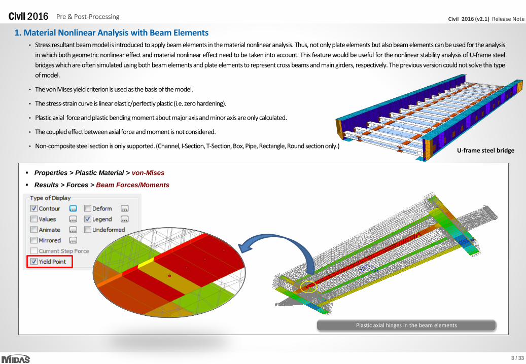
1. Material Nonlinear Analysis with Beam Elements
Properties > Plastic Material > von-Mises
Results > Forces > Beam Forces/Moments
• Stress resultant beam model is introduced to apply beam elements in the material nonlinear analysis. Thus, not only plate elements but also beam elements can be used for the analysis
in which both geometric nonlinear effect and material nonlinear effect need to be taken into account. This feature would be useful for the nonlinear stability analysis of U-frame steel
bridges which are often simulated using both beam elements and plate elements to represent cross beams and main girders, respectively. The previous version could not solve this type
of model.
• The von Mises yieldcriterionis used as the basis of the model.
• The stress-straincurve is linearelastic/perfectlyplastic (i.e. zerohardening).
• Plastic axial force andplastic bendingmomentabout majoraxisandminor axisare only calculated.
• The coupled effect betweenaxial force andmoment is not considered.
• Non-compositesteel section is only supported.(Channel, I-Section, T-Section, Box, Pipe, Rectangle,Round sectiononly.)
Plastic axial hinges in the beam elements
U-frame steel bridge
4 / 33
Civil 2016 (v2.1) Release NoteCivil 2016 Pre & Post-Processing
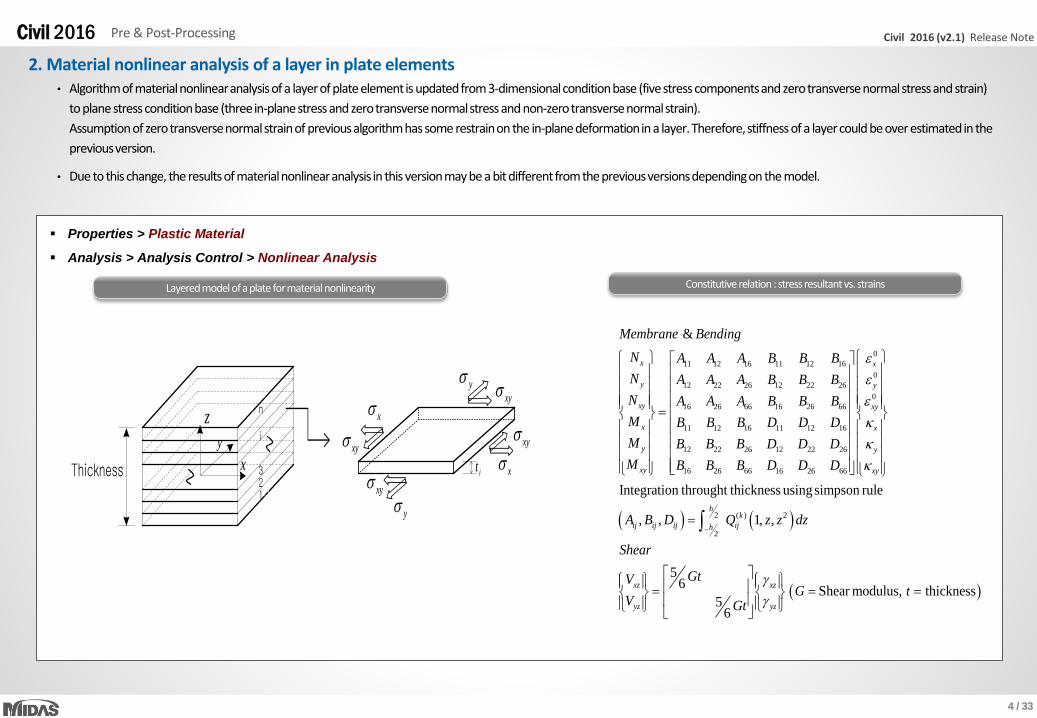
2. Material nonlinear analysis of a layer in plate elements
Properties > Plastic Material
Analysis > Analysis Control > Nonlinear Analysis
• Algorithm of material nonlinear analysis of a layer of plate element is updated from 3-dimensional condition base (five stress components and zero transverse normal stress and strain)
to plane stress condition base (three in-plane stress and zero transverse normal stress and non-zero transverse normal strain).
Assumption of zero transverse normal strain of previous algorithm has some restrain on the in-plane deformation in a layer. Therefore, stiffness of a layer could be over estimated in the
previous version.
• Due to this change, the results of material nonlinear analysis in this version may be a bit different from the previous versionsdepending on the model.
Constitutive relation : stress resultant vs. strains
Thickness
x
x
y
y
xy xy
xy
xyit
123
i
n
x
y
z
0
11 12 16 11 12 16
0
12 22 26 12 22 26
0
16 26 66 16 26 66
11 12 16 11 12 16
12 22 26 12 22 26
16 26 66 16 26 66
&
x x
y y
xy xy
x x
y y
xy xy
Membrane Bending
N A A A B B B
N A A A B B B
N A A A B B B
M B B B D D D
M B B B D D D
M B B B D D D
2 ( ) 2
2
Integration throught thickness using simpson rule
, , 1, ,
56
Shear modulus, thickness5
6
hk
ij ij ij ijh
xz xz
yz yz
A B D Q z z dz
Shear
GtVG t
V Gt
Layered model of a plate for material nonlinearity
5 / 33
Civil 2016 (v2.1) Release NoteCivil 2016 Pre & Post-Processing
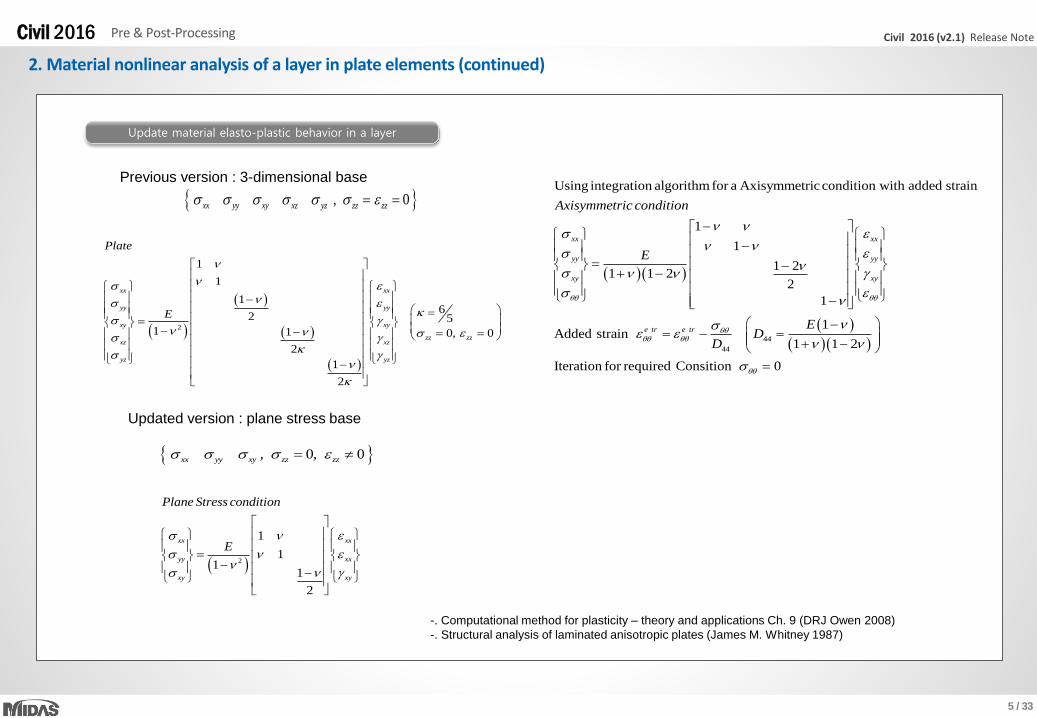
2. Material nonlinear analysis of a layer in plate elements (continued)
Update material elasto-plastic behavior in a layer
Previous version : 3-dimensional base
2
1
1
16
2 51 1 0, 0
2
1
2
xx xx
yy yy
xy xy
zz zzxz xz
yz yz
Plate
E
Updated version : plane stress base
, 0, 0xx yy xy zz zz
, 0xx yy xy xz yz zz zz
2
1
11
1
2
xx xx
yy xx
xy xy
Plane Stress condition
E
Using integration algorithm for a Axisymmetric condition with added strain
1
1
1 21 1 2
2
1
Added strain
xx xx
yy yy
xy xy
e tr
Axisymmetric condition
E
44
44
1
1 1 2
Iteration for required Consition 0
e trE
DD
-. Computational method for plasticity – theory and applications Ch. 9 (DRJ Owen 2008)
-. Structural analysis of laminated anisotropic plates (James M. Whitney 1987)

6 / 33
Civil 2016 (v2.1) Release NoteCivil 2016 Pre & Post-Processing
3. Triple Friction Pendulum Isolator
Boundary > Link > General Link > General Link Properties
• The Triple Friction Pendulum Isolator (TFPI) is now implemented. The TFPI exhibits multiple changes in stiffness and strength with increasing amplitude of displacement. It is known that
the TFPI offers better seismic performance, lower bearing costs, and lower construction costs as compared to conventional seismic isolation technology. The properties of each of the
bearing’s three pendulums are chosen to become sequentially active at different earthquake strengths. As the ground motions become stronger, the bearing displacements increase. At
greaterdisplacements,the effective pendulumlengthand effectivedamping increase,resultingin lowerseismic forcesand bearingdisplacements.
Triple Pendulum Bearing

7 / 33
Civil 2016 (v2.1) Release NoteCivil 2016 Pre & Post-Processing
3. Triple Friction Pendulum Isolator (continued)
Behavior of Triple Friction Pendulum Isolator (Sliding Regime I)
• Displaced shape
• Free body diagrams of the triple FP
Sliding occurs on surface 2 and 3 only.
Motion has not yet been initiated on surfaces 1 and 4.
W : Axial Force
-60
-40
-20
0
20
40
60
-0.002 -0.001 0 0.001 0.002
Fo
rce (
kN
)
Displacement (m)
Force-Displacement
8 / 33
Civil 2016 (v2.1) Release NoteCivil 2016 Pre & Post-Processing
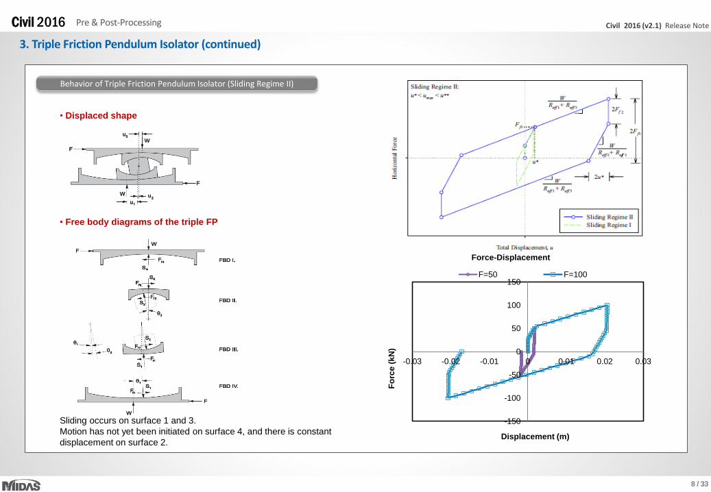
3. Triple Friction Pendulum Isolator (continued)
Behavior of Triple Friction Pendulum Isolator (Sliding Regime II)
• Displaced shape
• Free body diagrams of the triple FP
Sliding occurs on surface 1 and 3.
Motion has not yet been initiated on surface 4, and there is constant
displacement on surface 2.
-150
-100
-50
0
50
100
150
-0.03 -0.02 -0.01 0 0.01 0.02 0.03
Fo
rce
(k
N)
Displacement (m)
Force-Displacement
F=50 F=100
9 / 33
Civil 2016 (v2.1) Release NoteCivil 2016 Pre & Post-Processing
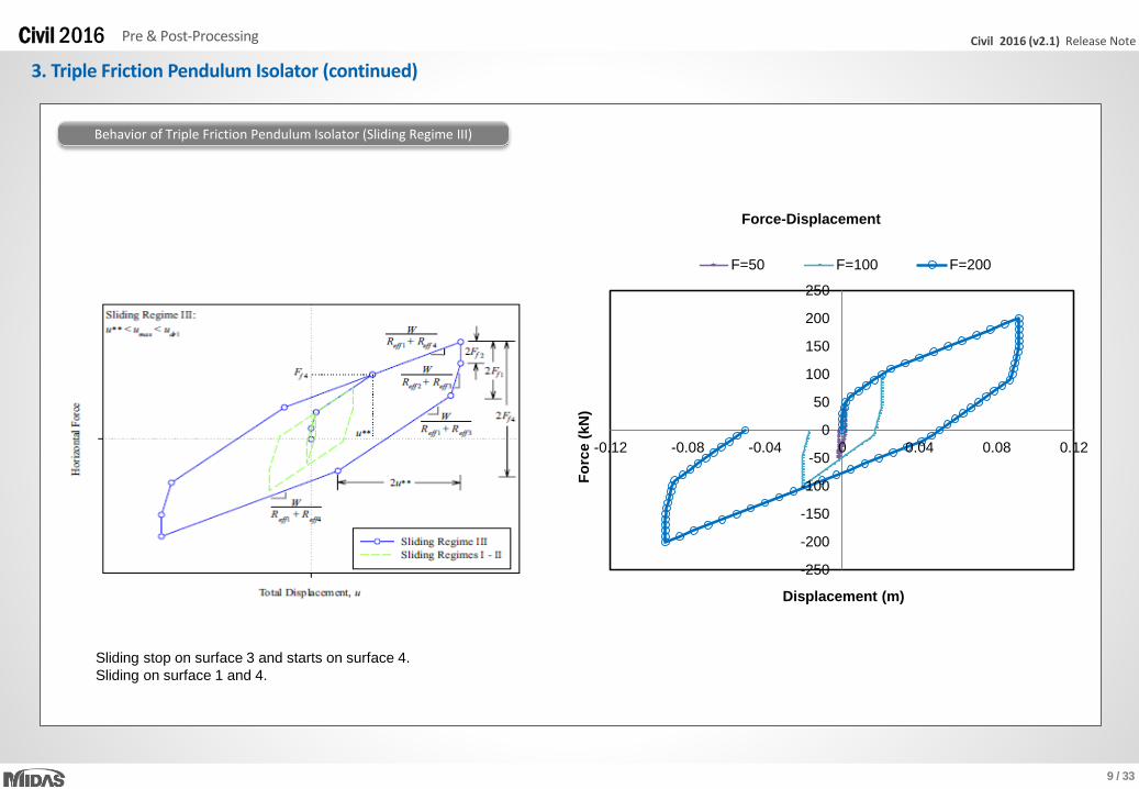
3. Triple Friction Pendulum Isolator (continued)
Behavior of Triple Friction Pendulum Isolator (Sliding Regime III)
-250
-200
-150
-100
-50
0
50
100
150
200
250
-0.12 -0.08 -0.04 0 0.04 0.08 0.12
Fo
rce (
kN
)Displacement (m)
Force-Displacement
F=50 F=100 F=200
Sliding stop on surface 3 and starts on surface 4.
Sliding on surface 1 and 4.

10 / 33
Civil 2016 (v2.1) Release NoteCivil 2016 Pre & Post-Processing
3. Triple Friction Pendulum Isolator (continued)
Behavior of Triple Friction Pendulum Isolator (Sliding Regime IV)
• Displaced shape
• Free body diagrams of the triple FP
The slider is on the displacement restrainer on surface 1.
Sliding occurs on surface 2 and 4, and the displacement on surface 3 remains
constant.
-300
-200
-100
0
100
200
300
-0.15 -0.1 -0.05 0 0.05 0.1 0.15
Fo
rce (
kN
)
Displacement (m)
Force-Displacement
F=50 F=100 F=200 F=250

11 / 33
Civil 2016 (v2.1) Release NoteCivil 2016 Pre & Post-Processing
3. Triple Friction Pendulum Isolator (continued)
Behavior of Triple Friction Pendulum Isolator (Sliding Regime V)
-500
-400
-300
-200
-100
0
100
200
300
400
500
-0.15 -0.1 -0.05 0 0.05 0.1 0.15
Fo
rce(k
N)
Displacement (m)
Force-Displacement
F=50 F=100 F=200 F=250 F=400
12 / 33
Civil 2016 (v2.1) Release NoteCivil 2016 Pre & Post-Processing
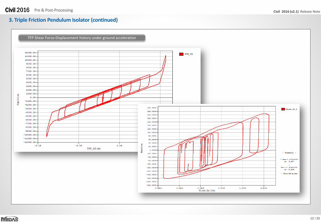
3. Triple Friction Pendulum Isolator (continued)
TFP Shear Force-Displacement history under ground acceleration
13 / 33
Civil 2016 (v2.1) Release NoteCivil 2016 Pre & Post-Processing
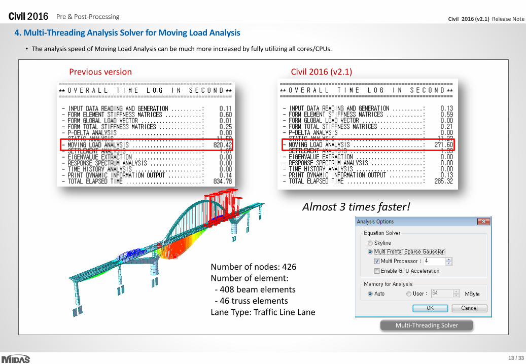
4. Multi-Threading Analysis Solver for Moving Load Analysis
Multi-Threading Solver
• The analysis speed of Moving Load Analysis can be much more increased by fully utilizing all cores/CPUs.
Previous version Civil 2016 (v2.1)
Number of nodes: 426Number of element:- 408 beam elements- 46 truss elements
Lane Type: Traffic Line Lane
Almost 3 times faster!
14 / 33
Civil 2016 (v2.1) Release NoteCivil 2016 Pre & Post-Processing
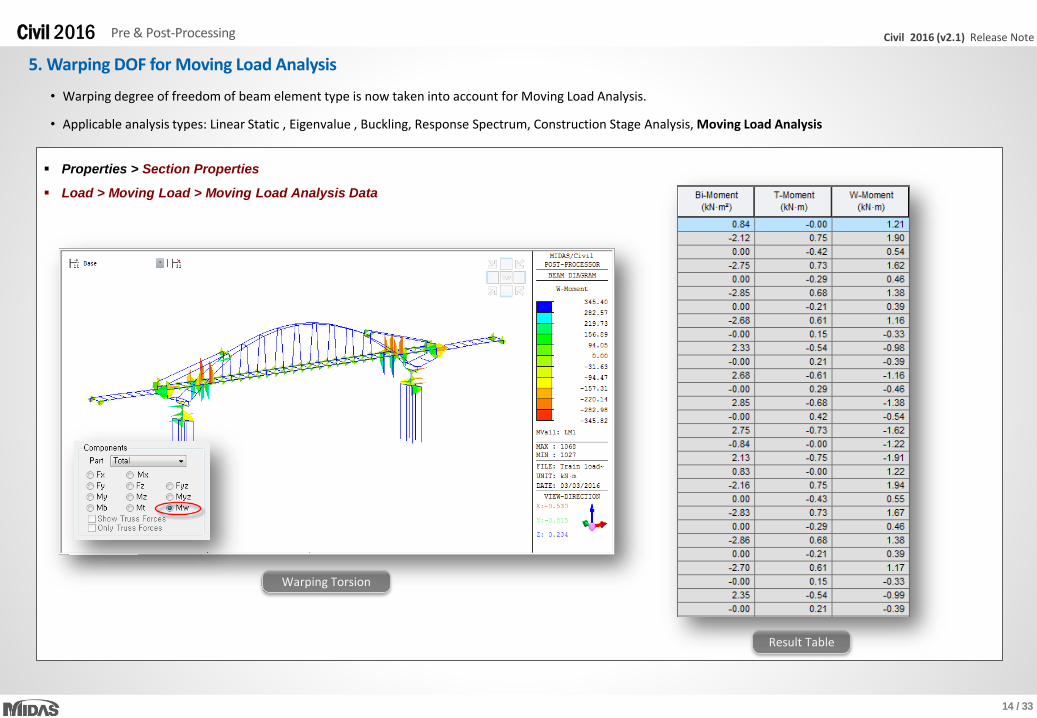
5. Warping DOF for Moving Load Analysis
• Warping degree of freedom of beam element type is now taken into account for Moving Load Analysis.
• Applicable analysis types: Linear Static , Eigenvalue , Buckling, Response Spectrum, Construction Stage Analysis, Moving Load Analysis
Warping Torsion
Result Table
Properties > Section Properties
Load > Moving Load > Moving Load Analysis Data
15 / 33
Civil 2016 (v2.1) Release NoteCivil 2016 Pre & Post-Processing
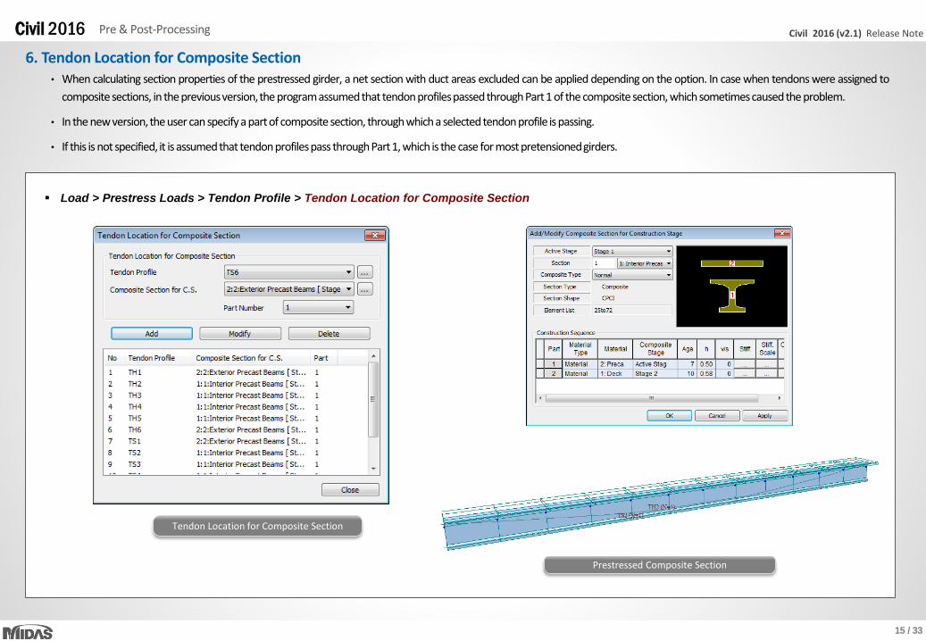
• When calculating section properties of the prestressed girder, a net section with duct areas excluded can be applied depending on the option. In case when tendons were assigned to
composite sections, in the previousversion,the programassumedthat tendonprofilespassedthroughPart1 of the composite section, whichsometimescausedthe problem.
• In the new version,the user can specify a partof composite section, throughwhicha selectedtendonprofile is passing.
• If this is not specified, it is assumedthat tendonprofilespass throughPart1, which is the case for most pretensionedgirders.
6. Tendon Location for Composite Section
Load > Prestress Loads > Tendon Profile > Tendon Location for Composite Section
Tendon Location for Composite Section
Prestressed Composite Section
16 / 33
Civil 2016 (v2.1) Release NoteCivil 2016 Analysis & Design
Vehicle locations considered
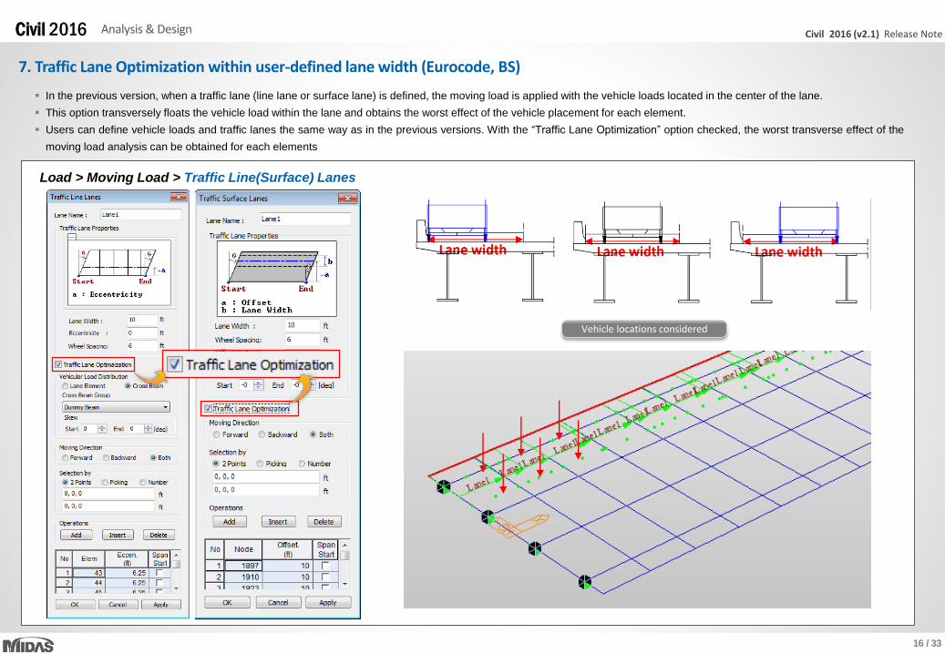
7. Traffic Lane Optimization within user-defined lane width (Eurocode, BS)
Load > Moving Load > Traffic Line(Surface) Lanes
In the previous version, when a traffic lane (line lane or surface lane) is defined, the moving load is applied with the vehicle loads located in the center of the lane.
This option transversely floats the vehicle load within the lane and obtains the worst effect of the vehicle placement for each element.
Users can define vehicle loads and traffic lanes the same way as in the previous versions. With the “Traffic Lane Optimization” option checked, the worst transverse effect of the
moving load analysis can be obtained for each elements
17 / 33
Civil 2016 (v2.1) Release NoteCivil 2016 Analysis & Design
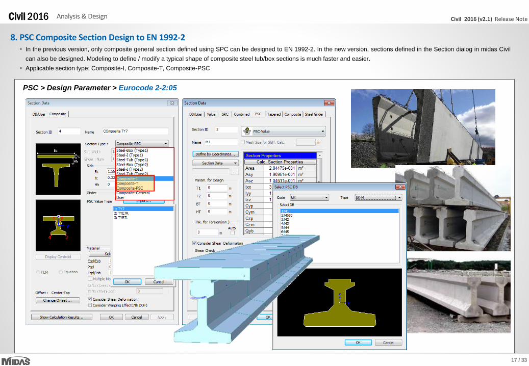
8. PSC Composite Section Design to EN 1992-2
PSC > Design Parameter > Eurocode 2-2:05
In the previous version, only composite general section defined using SPC can be designed to EN 1992-2. In the new version, sections defined in the Section dialog in midas Civil
can also be designed. Modeling to define / modify a typical shape of composite steel tub/box sections is much faster and easier.
Applicable section type: Composite-I, Composite-T, Composite-PSC
18 / 33
Civil 2016 (v2.1) Release NoteCivil 2016 Analysis & Design
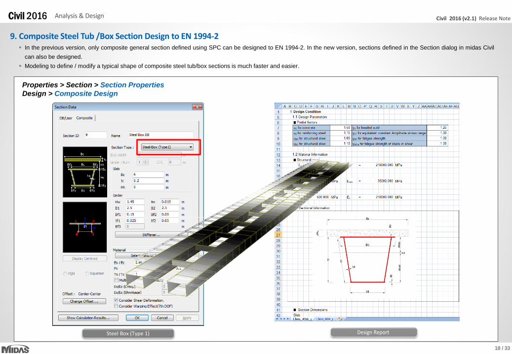
9. Composite Steel Tub /Box Section Design to EN 1994-2
Properties > Section > Section Properties
Design > Composite Design
In the previous version, only composite general section defined using SPC can be designed to EN 1994-2. In the new version, sections defined in the Section dialog in midas Civil
can also be designed.
Modeling to define / modify a typical shape of composite steel tub/box sections is much faster and easier.
Steel Box (Type 1)
19 / 33
Civil 2016 (v2.1) Release NoteCivil 2016 Analysis & Design
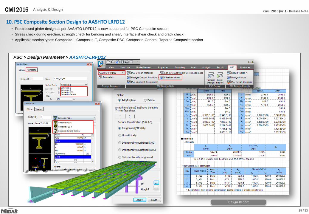
10. PSC Composite Section Design to AASHTO LRFD12
PSC > Design Parameter > AASHTO-LRFD12
Prestressed girder design as per AASHTO-LRFD12 is now supported for PSC Composite section.
Stress check during erection, strength check for bending and shear, interface shear check and crack check.
Applicable section types: Composite-I, Composite-T, Composite-PSC, Composite-General, Tapered Composite section
Design Report
20 / 33
Civil 2016 (v2.1) Release NoteCivil 2016 Analysis & Design
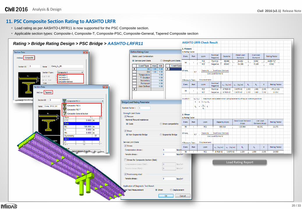
11. PSC Composite Section Rating to AASHTO LRFR
Rating > Bridge Rating Design > PSC Bridge > AASHTO-LRFR11
Load rating as per AASHTO-LRFR11 is now supported for the PSC Composite section.
Applicable section types: Composite-I, Composite-T, Composite-PSC, Composite-General, Tapered Composite section
Load Rating Report
21 / 33
Civil 2016 (v2.1) Release NoteCivil 2016 Analysis & Design
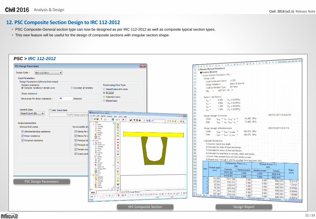
12. PSC Composite Section Design to IRC 112-2012
PSC > IRC 112-2012
PSC Composite-General section type can now be designed as per IRC 112-2012 as well as composite typical section types.
This new feature will be useful for the design of composite sections with irregular section shape.
PSC Design Parameters
SPC Composite Section Design Report

22 / 33
Civil 2016 (v2.1) Release NoteCivil 2016 Analysis & Design
13. Reinforced Concrete Section Design to IRC 112-2011
PSC > RC Design > IRC 112-2011
Reinforced concrete section can now be designed as per IRC 112-2011.
Design Result Table Design Summary Report
23 / 33
Civil 2016 (v2.1) Release NoteCivil 2016 Pre & Post-Processing
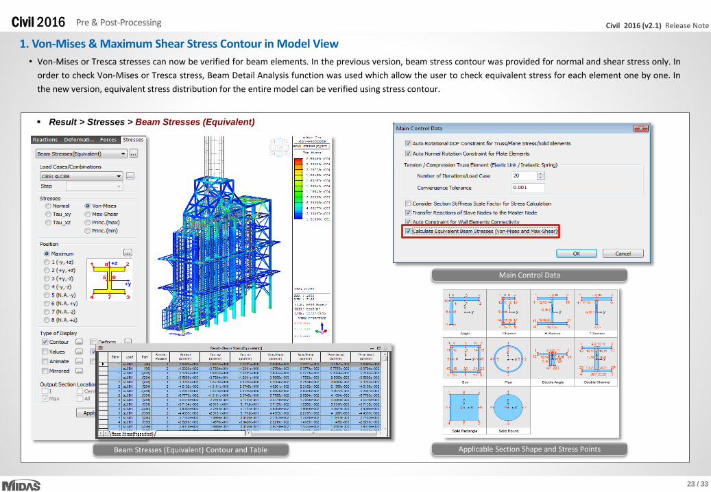
1. Von-Mises & Maximum Shear Stress Contour in Model View
• Von-Mises or Tresca stresses can now be verified for beam elements. In the previous version, beam stress contour was provided for normal and shear stress only. In
order to check Von-Mises or Tresca stress, Beam Detail Analysis function was used which allow the user to check equivalent stress for each element one by one. In
the new version, equivalent stress distribution for the entire model can be verified using stress contour.
Result > Stresses > Beam Stresses (Equivalent)
Beam Stresses (Equivalent) Contour and Table
Main Control Data
Applicable Section Shape and Stress Points

24 / 33
Civil 2016 (v2.1) Release NoteCivil 2016 Pre & Post-Processing
2. New Section and Material Database for Cold-formed Steel
• Cold-formed Channel, Pipe, Box and Upright section DB as per UNI (Italian standard) and SS (Singaporean Standard) has been newly implemented.
• Steel section DB as per ICHA (Chilean standard) has been added for Angle, Double Angle, Star Battened Angle, I-shape, Channel, Double Channel and Lipped channel.
• Cold-formed material DB as per EN10326, EN 10149-2 and EN 10149-3 has been newly implemented.
Properties > Section Properties
Properties > Material Properties
UNI Upright Section SS Cold Formed Channel ICHA Double Angle
25 / 33
Civil 2016 (v2.1) Release NoteCivil 2016 Pre & Post-Processing
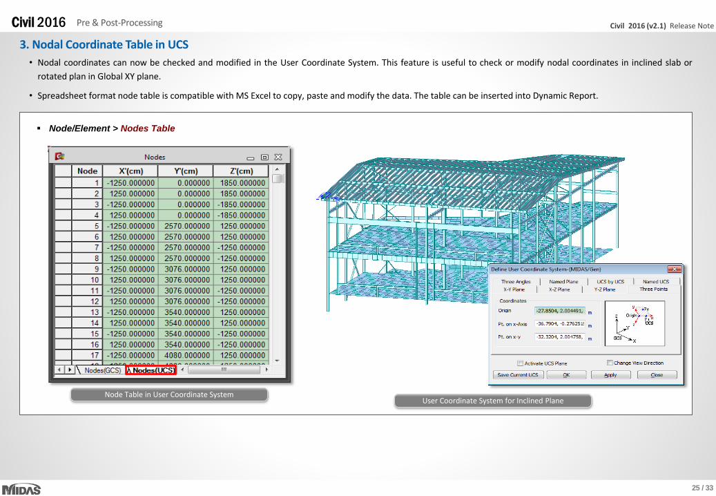
3. Nodal Coordinate Table in UCS
Node/Element > Nodes Table
User Coordinate System for Inclined PlaneNode Table in User Coordinate System
• Nodal coordinates can now be checked and modified in the User Coordinate System. This feature is useful to check or modify nodal coordinates in inclined slab or
rotated plan in Global XY plane.
• Spreadsheet format node table is compatible with MS Excel to copy, paste and modify the data. The table can be inserted into Dynamic Report.
26 / 33
Civil 2016 (v2.1) Release NoteCivil 2016 Pre & Post-Processing
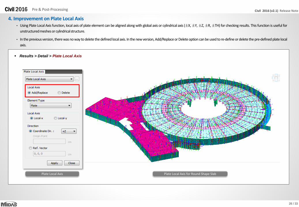
• Using Plate Local Axis function, local axis of plate element can be aligned along with global axis or cylindrical axis (±X,±Y,±Z,±R,±TH) for checking results. This function is useful for
unstructuredmeshes or cylindricalstructure.
• In the previous version, there was no way to delete the defined local axis. In the new version, Add/Replace or Delete option can be used to re-define or delete the pre-defined plate local
axis.
4. Improvement on Plate Local Axis
Results > Detail > Plate Local Axis
Plate Local Axis Plate Local Axis for Round Shape Slab
27 / 33
Civil 2016 (v2.1) Release NoteCivil 2016 Pre & Post-Processing
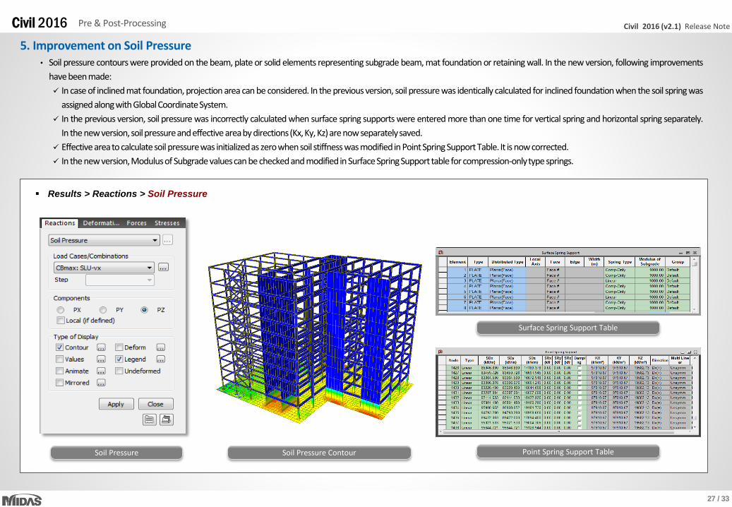
• Soil pressure contours were provided on the beam, plate or solid elements representing subgrade beam, mat foundation or retaining wall. In the new version, following improvements
have beenmade:
In case of inclined mat foundation, projection area can be considered. In the previous version, soil pressure was identically calculated for inclined foundation when the soil spring was
assigned alongwithGlobalCoordinateSystem.
In the previous version, soil pressure was incorrectly calculated when surface spring supports were entered more than one time for vertical spring and horizontal spring separately.
In the new version,soilpressureandeffective areaby directions(Kx,Ky, Kz)are now separatelysaved.
Effective areato calculate soil pressurewas initializedas zerowhensoil stiffness was modifiedin PointSpring SupportTable. It is now corrected.
In the new version,Modulusof Subgrade valuescan be checkedand modifiedin Surface SpringSupport table for compression-onlytype springs.
5. Improvement on Soil Pressure
Results > Reactions > Soil Pressure
Soil Pressure Soil Pressure Contour
Surface Spring Support Table
Point Spring Support Table

28 / 33
Civil 2016 (v2.1) Release NoteCivil 2016 Pre & Post-Processing
Report Tree
6. Different Unit Setting for Tables and Graphs in Dynamic Report
Tools > Dynamic Report Generator
In the previous version, units of tables and graphs in the dynamic report were always identical to the global unit system. In the new version, different unit system can be specified
by each tables and graphs separately.
Table/Chart Unit Dialog Box

29 / 33
Civil 2016 (v2.1) Release NoteCivil 2016 Pre & Post-Processing
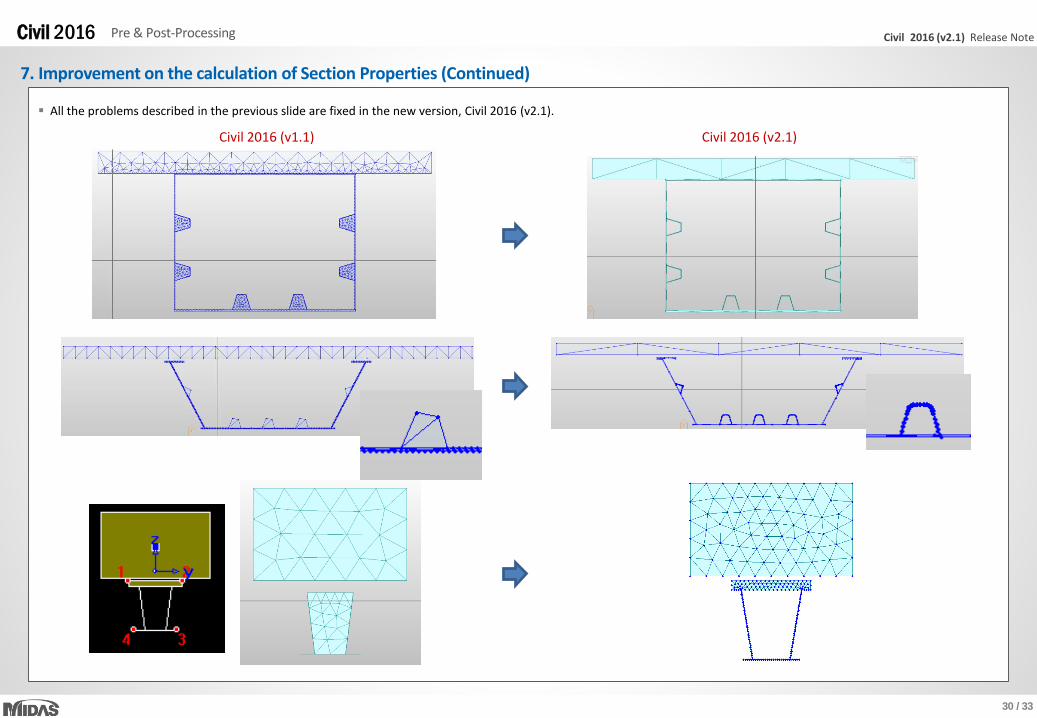
7. Improvement on the calculation of Section Properties
In the previous version, Civil 2016 (v1.1), the warping DOF was newly introduced for the beam element type. In order to calculate warping constant of the sections, the method of
calculating section properties had to be changed including shear area and torsional constant for the PSC section and Composite section. The section properties were obtained by
generating mesh for the beam section. When generating this mesh, however, there were some errors in the calculation of section properties in case of steel composite section with
longitudinal stiffeners as follows:
Error: The inside of longitudinal stiffeners was filled.
Error: When neutral axis was located within the slab, the inside of steel box was filled.
Error: It took very long time to run models in which steel composite sections with very thin component or tapered section group were included.
30 / 33
Civil 2016 (v2.1) Release NoteCivil 2016 Pre & Post-Processing
7. Improvement on the calculation of Section Properties (Continued)
All the problems described in the previous slide are fixed in the new version, Civil 2016 (v2.1).
Civil 2016 (v1.1) Civil 2016 (v2.1)
31 / 33
Civil 2016 (v2.1) Release NoteCivil 2016 Pre & Post-Processing
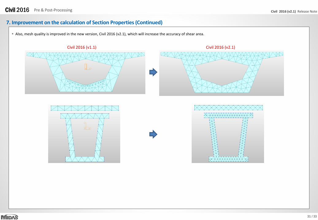
7. Improvement on the calculation of Section Properties (Continued)
Also, mesh quality is improved in the new version, Civil 2016 (v2.1), which will increase the accuracy of shear area.
Civil 2016 (v1.1) Civil 2016 (v2.1)

32 / 33
Civil 2016 (v2.1) Release NoteCivil 2016 Pre & Post-Processing
7. Improvement on the calculation of Section Properties (Continued)
• Test model 1
– Steel Composite Girder Bridge
– Tapered Section Group
– 1901 elements
Running time Improvement
Civil 2016 (v1.1) 2 hours
Civil 2016 (v2.1) 1 min. 16 sec. 95 times faster
• Comparison
Model running time is much reduced in the new version, Civil 2016 (v2.1).
• Test model 2
– Steel Composite Girder Bridge
– Tapered Section Group
– 4281 elements
Running time Improvement
Civil 2016 (v1.1) 1 hour 19 min.
Civil 2016 (v2.1) 46 sec. 103 times faster
• Comparison

33 / 33
Civil 2016 (v2.1) Release NoteCivil 2016 Pre & Post-Processing
7. Improvement on the calculation of Section Properties (Continued)
There is no change in the calculation of the torsional constant of the Composite Steel-I, Composite-I section type in the new version, Civil 2016 (v2.1). It is calculated as follows:
Important notice:
1) Section properties can be different between previous version and new version.
2) Section properties calculated in the previous versions will not automatically be recalculated by just opening a model file (mcb format) in the new version, Civil 2016 (v2.1). It
will be recalculated only when hitting the ‘Show Calculation Results’ button or the ‘OK’ button in the Section dialog.
3) When mct file exported from the previous versions is imported into the new version, the section properties are automatically recalculated except for built-in database
section.