reliability, maintainability, and availability (rma) handbook · faa...
TRANSCRIPT
FAA Reliability, Maintainability, and Availability (RMA) HandbookFAA RMA-HDBK-006C V1.1
U.S. Department of Transportation Federal Aviation Administration
Reliability, Maintainability, and Availability (RMA) Handbook
November 19, 2015 FAA RMA-HDBK-006C V1.1
Federal Aviation Administration 800 Independence Avenue, SW
Washington, DC 20591

FAA Reliability, Maintainability, and Availability (RMA) Handbook
FAA RMA-HDBK-006C V1.1
i
THIS PAGE LEFT INTENTIONALLY BLANK
FAA Reliability, Maintainability, and Availability (RMA) Handbook
FAA RMA-HDBK-006C V1.1
ii
Table of Contents
SCOPE ................................................................................................................................... 17
DOCUMENT OVERVIEW ................................................................................................. 19
APPLICABLE DOCUMENTS .......................................................................................... 22
3.1 Specifications, standards, and handbooks ......................................................................... 22
3.2 FAA Orders ....................................................................................................................... 22
3.3 Non-Government Publications.......................................................................................... 22
DEFINITIONS ...................................................................................................................... 23
PURPOSE AND OBJECTIVES .......................................................................................... 32
5.1 Background ....................................................................................................................... 32
RMA REQUIREMENTS MANAGEMENT APPROACH .............................................. 34
DERIVATION OF NAS-LEVEL RMA REQUIREMENTS ............................................ 36
7.1 NAS-RD-2013 Severity Assessment Process ................................................................... 36
7.1.1 Severity Level Assessment ............................................................................................ 36
7.1.2 Severity Level Assessment Roll-Up .............................................................................. 38
7.2 Development of Service Threads ...................................................................................... 39
7.2.1 System of Systems Taxonomy of FAA Systems ........................................................... 40
7.2.2 Categorization of NAPRS Services ............................................................................... 42
7.3 Service Thread Contribution ............................................................................................. 46
7.4 Scaling of Service Threads ............................................................................................... 50
7.4.1 Facility Grouping Schema ............................................................................................. 50
7.4.1.1 ARTCCs ...................................................................................................................... 52
7.4.1.2 TRACONs................................................................................................................... 52
7.4.1.3 ATCTs......................................................................................................................... 54
7.4.1.4 Unstaffed Facilities ..................................................................................................... 54
7.4.2 Scaling Service Threads to Facility Groups................................................................... 54
7.4.3 Environmental Complications ....................................................................................... 55
7.5 Assign Service Thread Loss Severity Category................................................................ 55
7.6 STLSC Matrix Development ............................................................................................ 57
7.6.1 Terminal STLSC Matrix ................................................................................................ 59
7.6.2 En Route STLSC Matrix ................................................................................................ 61
7.6.3 “Other” Service Thread STLSC Matrix ......................................................................... 62
7.7 NAS-RD-2013 RMA Requirements ................................................................................. 64
7.7.1 Information Systems ...................................................................................................... 65
FAA Reliability, Maintainability, and Availability (RMA) Handbook
FAA RMA-HDBK-006C V1.1
iii
7.7.2 Remote/Distributed and Standalone Systems ................................................................ 69
7.7.3 Infrastructure and Enterprise Systems ........................................................................... 71
7.7.3.1 Power Systems ............................................................................................................ 72
7.7.3.2 Heating, Ventilation and Air Conditioning (HVAC) Subsystems .............................. 76
7.7.3.3 Enterprise Infrastructure ............................................................................................. 77
7.7.3.3.1 Overview of Enterprise Infrastructure Systems ....................................................... 77
7.7.3.3.1.1 Service-Oriented Architecture .............................................................................. 77
7.7.3.3.1.2 Cloud Architectures .............................................................................................. 79
7.7.3.3.2 Communications Transport ...................................................................................... 80
7.7.3.3.3 Deriving RMA Requirements for Enterprise Infrastructure Systems (EIS) ............ 81
7.7.3.3.4 Increasing Reliability in EISs .................................................................................. 85
7.8 Summary of Process for Deriving RMA Requirements ................................................... 88
ACQUISITION STRATEGIES AND GUIDANCE .......................................................... 89
8.1 Preliminary Requirements Analysis ................................................................................. 89
8.1.1 System of Systems Taxonomy of FAA NAS Systems and Associated Allocation
Methods...................................................................................................................................... 90
8.1.1.1 Information Systems ................................................................................................... 91
8.1.1.2 Remote/Distributed and Standalone Systems ............................................................. 92
8.1.1.3 Mission Support Systems ............................................................................................ 94
8.1.1.4 Infrastructure and Enterprise Systems ........................................................................ 94
8.1.1.4.1 Power Systems ......................................................................................................... 95
8.1.1.4.2 HVAC Subsystems .................................................................................................. 96
8.1.1.4.3 Communications Transport ...................................................................................... 97
8.1.1.4.4 Enterprise Infrastructure Systems (EIS) .................................................................. 97
8.1.2 Analyzing Scheduled Downtime Requirements ............................................................ 98
8.1.3 Modifications to STLSC Levels .................................................................................... 99
8.1.4 Redundancy and Fault Tolerance Requirements ........................................................... 99
8.1.5 Preliminary Requirements Analysis Checklist ............................................................ 100
8.2 Procurement Package Preparation .................................................................................. 100
8.2.1 System Specification Document (SSD) ....................................................................... 100
8.2.1.1 System Quality Factors ............................................................................................. 101
8.2.1.2 System Design Characteristics .................................................................................. 107
8.2.1.3 System Operations .................................................................................................... 107
8.2.1.4 Leasing Services ....................................................................................................... 108
FAA Reliability, Maintainability, and Availability (RMA) Handbook
FAA RMA-HDBK-006C V1.1
iv
8.2.1.5 System Specification Document RMA Checklist ..................................................... 109
8.2.2 Statement of Work ....................................................................................................... 109
8.2.2.1 Technical Interchange Meetings ............................................................................... 109
8.2.2.2 Documentation .......................................................................................................... 110
8.2.2.3 Risk Reduction Activities ......................................................................................... 113
8.2.2.4 Reliability Modeling ................................................................................................. 113
8.2.2.5 Performance Modeling.............................................................................................. 113
8.2.2.6 Monitor and Control Design Requirement ............................................................... 113
8.2.2.7 Fault Avoidance Strategies ....................................................................................... 114
8.2.2.8 Reliability Growth .................................................................................................... 114
8.2.2.9 Statement of Work Checklist .................................................................................... 115
8.2.3 Information for Proposal Preparation .......................................................................... 115
8.2.3.1 Inherent Availability Model ...................................................................................... 115
8.2.3.2 Proposed M&C Design Description and Specifications ........................................... 115
8.2.3.3 Fault Tolerant Design Description ............................................................................ 116
8.3 Proposal Evaluation ........................................................................................................ 116
8.3.1 Reliability, Maintainability and Availability Modeling and Assessment .................... 116
8.3.2 Fault-Tolerant Design Evaluation ................................................................................ 116
8.3.3 Performance Modeling and Assessment ...................................................................... 116
8.4 Contractor Design Monitoring ........................................................................................ 117
8.4.1 Formal Design Reviews ............................................................................................... 117
8.4.2 Technical Interchange Meetings .................................................................................. 117
8.4.3 Risk Management ........................................................................................................ 117
8.4.3.1 Fault Tolerance Infrastructure Risk Management .................................................... 118
8.4.3.1.1 Application Fault Tolerance Risk Management .................................................... 119
8.4.3.2 Performance Monitoring Risk Management ............................................................. 120
8.4.3.3 Software Reliability Growth Plan Monitoring .......................................................... 120
8.5 Design Validation and Acceptance Testing .................................................................... 121
8.5.1 Fault Tolerance Diagnostic Testing ............................................................................. 121
8.5.2 Functional Testing ....................................................................................................... 121
8.5.3 Reliability Growth Testing .......................................................................................... 121
SERVICE THREAD MANAGEMENT ........................................................................... 123
9.1 Revising Service Thread Requirements .......................................................................... 123
9.2 Adding a New Service Thread ........................................................................................ 123
FAA Reliability, Maintainability, and Availability (RMA) Handbook
FAA RMA-HDBK-006C V1.1
v
9.3 FSEP and NAPRS ........................................................................................................... 124
RMA REQUIREMENTS ASSESSMENT ........................................................................ 125
10.1 RMA Feedback Paths ..................................................................................................... 125
10.2 Requirements Analysis ................................................................................................... 129
10.3 Architecture Assessment ................................................................................................. 130
NOTES ................................................................................................................................. 132
11.1 Updating this Handbook ................................................................................................. 132
11.2 Bibliography ................................................................................................................... 132
11.3 References ....................................................................................................................... 133
Appendix A SAMPLE REQUIREMENTS .......................................................................... 141
A.1 System Quality Factors ................................................................................................... 141
A.2 System Design Characteristics ........................................................................................ 142
A.3 System Operations .......................................................................................................... 144
RELIABILITY/AVAILABILITY TABLES FOR REPAIRABLE
REDUNDANT SYSTEMS ....................................................................................................... 165
B.1 Availability Table ........................................................................................................... 165
B.2 Mean Time between Failure (MTBF) Graphs ................................................................ 166
STATISTICAL METHODS AND LIMITATIONS ...................................... 170
C.1 Reliability Modeling and Prediction ............................................................................... 170
C.2 Maintainability ................................................................................................................ 171
C.3 Availability ..................................................................................................................... 171
C.4 Modeling Repairable Redundant Systems ...................................................................... 172
C.5 Availability Allocation.................................................................................................... 179
C.6 Modeling and Allocation Issues ...................................................................................... 181
FORMAL RELIABILITY DEMONSTRATION TEST PARAMETERS . 183
SERVICE THREAD DIAGRAM AND DEFINITIONS .............................. 188
EVOLUTION OF THE FAA RMA PARADIGM ......................................... 215
F.1 The Traditional RMA Paradigm ..................................................................................... 215
F.2 Agents of Change ............................................................................................................ 215
F.2.1 Technology and Requirements Driven Reliability Improvements .............................. 216
F.2.2 Fundamentals Statistical Limitations ........................................................................... 217
F.2.2.1 Reliability Modeling ................................................................................................. 217
F.2.2.2 Reliability Verification and Demonstration .............................................................. 219
F.2.3 Use of Availability as a Conceptual Specification ...................................................... 220
FAA Reliability, Maintainability, and Availability (RMA) Handbook
FAA RMA-HDBK-006C V1.1
vi
F.2.4 RMA Issues for Software-Intensive Systems .............................................................. 221
F.2.4.1 Software Reliability Characteristics ......................................................................... 221
F.2.4.1.1 Software Reliability Curve .................................................................................... 223
F.2.4.2 Software Reliability Growth ..................................................................................... 224
F.2.4.2.1 Reliability Growth Program ................................................................................... 224
F.2.4.2.2 Reliability Growth Process .................................................................................... 224
F.2.5 RMA Considerations for Systems Using COTS or NDI Hardware Elements ............. 225
SOFTWARE RELIABILITY GROWTH IN THE ENGINEERING LIFE-
CYCLE 226
G.1 Relevant Software Identification .................................................................................... 226
G.2 Effort Identification ........................................................................................................ 226
G.2.1 “Full” Effort ................................................................................................................. 229
G.2.2 “Moderate” Effort ........................................................................................................ 229
G.2.3 “Minimum” Effort ....................................................................................................... 229
G.2.4 “None” Effort ............................................................................................................... 229
G.3 Goals Guidance ............................................................................................................... 230
G.4 Overarching Methodologies & Tools ............................................................................. 239
G.4.1 Metrics ......................................................................................................................... 239
G.4.2 Software Fault Taxonomies ......................................................................................... 239
G.4.3 Tools ............................................................................................................................ 239
POWER SYSTEM CATEGORY ALLOCATIONS ..................................... 240
GLOSSARY ........................................................................................................ 243
I.1 Acronyms ........................................................................................................................ 243
I.2 Definitions....................................................................................................................... 248
QUICK LOOK GUIDE TO USE OF THIS HANDBOOK ........................... 251
FAA Reliability, Maintainability, and Availability (RMA) Handbook
FAA RMA-HDBK-006C V1.1
vii
Table of Figures
Figure 4-1 Operational Availability Entity-Relationship Diagram .............................................. 24
Figure 4-2 Failure / Restoration Timeline .................................................................................... 28
Figure 7-1 Functional Architecture ............................................................................................... 36
Figure 7-2 NAS System Taxonomy .............................................................................................. 42
Figure 7-3 Example Thread Diagram ........................................................................................... 46
Figure 7-4 Effect of Service Interruptions on NAS Capacity ....................................................... 46
Figure 7-5 Service Thread Loss Severity Categories - Case 1 ..................................................... 47
Figure 7-6 Potential Safety-Critical Service Thread - Case 2....................................................... 48
Figure 7-7 Decomposition of Safety-Critical Service into Threads ............................................. 49
Figure 7-8 Comparison of TRACONs over time by annual total number of operations .............. 53
Figure 7-9 Service/Function - Terminal Service Thread STLSC Matrix ..................................... 60
Figure 7-10 Service/Function – En Route Service Thread STLSC Matrix .................................. 61
Figure 7-11 Service/Function – “Other” Service Thread STLSC Matrix ..................................... 62
Figure 7-12 Example State Diagram............................................................................................. 65
Figure 7-13 Terminal Power System ............................................................................................ 74
Figure 7-14 En Route Power System ............................................................................................ 75
Figure 7-15 “Other” Power System .............................................................................................. 76
Figure 7-16 EIS Architecture for Essential Services .................................................................... 84
Figure 7-17 EIS Architecture for Efficiency-Critical Services..................................................... 85
Figure 8-1 Acquisition Process Flow Diagram ............................................................................. 89
Figure 8-2 NAS System of Systems Taxonomy ........................................................................... 90
Figure 10-1 RMA Process Diagram ........................................................................................... 125
Figure 10-2 Deployed System Performance Feedback Path....................................................... 126
Figure 10-3 Service Thread Availability Historgram ................................................................. 127
Figure 10-4 Reliability Histogram for Unscheduled Interruptions ............................................. 128
Figure 10-5 Requirements Analysis............................................................................................ 130
Figure 10-6 Architecture Assessment ......................................................................................... 131
Figure B-1 Mean Time between Failure for a "Two Needing One" Redundant Combination .. 167
Figure B-2 Mean Time between Failure for a “Two Needing One” Redundant Combination .. 168
Figure B-3 Mean Time between Failure for a “Two Needing One” Redundant Combination .. 169
Figure C-1 General State Transition Diagram for Three-State System ...................................... 174
Figure C-2 Simplified Transition Diagram ................................................................................. 176
Figure C-3 Coverage Failure ...................................................................................................... 178
Figure C-4 Availability Model.................................................................................................... 179
Figure D-1 Operating Characteristic Curves .............................................................................. 183
Figure D-2 Risks and Decision Points Associated with OC Curve ............................................ 184
Figure D-3 Effect of Increasing Test Time on OC Curve .......................................................... 185
Figure E-1 Functional Notional Architecture ............................................................................. 191
Figure E-2 Automatic Dependent Surveillance Service (ADSS) ............................................... 192
Figure E-3 Airport Surface Detection Equipment (ASDES) ...................................................... 192
Figure E-4 Beacon Data (Digitized) (BDAT) ............................................................................. 193
Figure E-5 Backup Emergency Communications Service (BUECS) ......................................... 193
Figure E-6 Composite Flight Data Processing Service (CFAD) ................................................ 194
Figure E-7 Composite Oceanic Display and Planning Service (CODAP) ................................. 194
Figure E-8 Anchorage Composite Offshore Flight Data Service (COFAD) .............................. 195
FAA Reliability, Maintainability, and Availability (RMA) Handbook
FAA RMA-HDBK-006C V1.1
viii
Figure E-9 Composite Radar Data Processing Service (CRAD) (CCCH/EBUS) ..................... 195
Figure E-10 Composite Radar Data Processing Service (CRAD) (EAS/EBUS) ....................... 196
Figure E-11 En Route Communications (ECOM) ...................................................................... 196
Figure E-12 En Route Terminal Automated Radar Service (ETARS) ....................................... 197
Figure E-13 FSS Communications Service (FCOM) ................................................................. 197
Figure E-14 Flight Data Entry and Printout Service (FDAT) ..................................................... 198
Figure E-15 Flight Data Input/Output Remote (FDIOR) ........................................................... 198
Figure E-16 Flight Service Station Automated Service (FSSAS) .............................................. 199
Figure E-17 Interfacility Data Service (IDAT) ........................................................................... 199
Figure E-18 Low Level Wind Service (LLWS) ......................................................................... 200
Figure E-19 MODE-S Data Link Data Service (MDAT) ........................................................... 200
Figure E-20 MODE-S Secondary Radar Service (MSEC) ......................................................... 201
Figure E-21 NADIN Service Threads (NADS, NAMS, NDAT) ............................................... 201
Figure E-22 Radar Data (Digitized) (RDAT) ............................................................................. 202
Figure E-23 Remote Monitoring/Maintenance Logging System Service (RMLSS) .................. 202
Figure E-24 Remote Tower Alphanumeric Display System Service (RTADS)......................... 203
Figure E-25 Remote Tower Display Service (RTDS) ................................................................ 203
Figure E-26 Runway Visual Range Service (RVRS) ................................................................. 204
Figure E-27 Terminal Automated Radar Service (TARS) ......................................................... 204
Figure E-28 Terminal Communications Service (TCOM) ......................................................... 205
Figure E-29 Terminal Doppler Weather Radar Service (TDWRS) ............................................ 205
Figure E-30 Traffic Flow Management System Service (TFMSS) ............................................ 206
Figure E-31 Terminal Radar Service (TRAD) ............................................................................ 206
Figure E-32 Terminal Surveillance Backup (TSB) (NEW) ........................................................ 207
Figure E-33 Terminal Secondary Radar (TSEC) ........................................................................ 207
Figure E-34 Terminal Voice Switch (TVS) (NAPRS Facility) .................................................. 208
Figure E-35 Terminal Voice Switch Backup (TVSB) (New) ..................................................... 208
Figure E-36 Visual Guidance Service (VGS) ............................................................................. 209
Figure E-37 VSCS Training and Backup System (VTABS) (NAPRS Facility) ........................ 209
Figure E-38 Voice Switching and Control System Service (VSCSS) ........................................ 210
Figure E-39 WAAS/GPS Service (WAAS) ................................................................................ 210
Figure E-40 WMSCR Data Service (WDAT) ............................................................................ 211
Figure E-41 WMSCR Service Threads (WMSCR) .................................................................... 211
Figure E-42 R/F Approach and Landing Services ...................................................................... 212
Figure E-43 R/F Navigation Service........................................................................................... 212
Figure E-44 ARTCC En Route Communications Services (Safety-Critical Thread Pair) ......... 213
Figure E-45 Terminal Voice Communications Safety-Critical Service Thread Pair ................. 213
Figure E-46 Terminal Surveillance Safety-Critical Service Thread Pair (1) .............................. 214
Figure E-47 Terminal Surveillance Safety-Critical Service Thread Pair (2) .............................. 214
Figure F-1 FAA System Reliability Improvements .................................................................... 216
Figure F-2 NAS Stage A Recovery Effectiveness ...................................................................... 218
Figure F-3 Coverage Sensitivity of Reliability Models .............................................................. 219
Figure F-4 Notional Hardware Failure Curve, ............................................................................ 223
Figure F-5 Notional Software Failure Curve .............................................................................. 223
Figure F-6 Notional Reliability Growth Management................................................................ 225
Figure H-1 Terminal STLSC with Power System ...................................................................... 240
FAA Reliability, Maintainability, and Availability (RMA) Handbook
FAA RMA-HDBK-006C V1.1
ix
Figure H-2 En Route STLSC with Power System ...................................................................... 241
Figure H-3 “Other” STLSC with Power System ........................................................................ 242
Figure J-1 FAA Lifecycle Management Process ........................................................................ 251
Figure J-2 ANG B Program Level Requirements Process.......................................................... 252
Figure J-3 RMA Process: IARD Phase ....................................................................................... 253
Figure J-4 STLSC Matrix Illustration ......................................................................................... 255
Figure J-5 Initial Investment Analysis Phase.............................................................................. 257
Figure J-6 RMA Process: Final Investment Analysis Phase ...................................................... 257
Figure J-7 Solution Implementation Phase ................................................................................. 258
Figure J-8 In-Service Management Phase .................................................................................. 259
FAA Reliability, Maintainability, and Availability (RMA) Handbook
FAA RMA-HDBK-006C V1.1
x
Table of Tables
Table 7-1 NAS Architecture Services and Functions ................................................................... 37
Table 7-2 Mapping of NAPRS Services and Service Threads ..................................................... 44
Table 7-3 Summary of Mapping of Service Threads to STLSC Matrices ................................... 45
Table 7-4 Facility Grouping and Descriptions.............................................................................. 51
Table 7-5 TRACON Grouping ..................................................................................................... 53
Table 7-6 Criteria Used for Tower Classification [73] ................................................................. 54
Table 7-7 Noted Discrepancies ..................................................................................................... 63
Table 7-8 Information Service Thread Reliability, Maintainability, and Recovery Times .......... 66
Table 7-9 Remote/ Distributed and Standalone Systems Services Thread ................................... 70
Table 7-10 RMA Characteristics of FTI Services ........................................................................ 81
Table 7-11 Enterprise Infrastructure Architecture (EIS) .............................................................. 83
Table 8-1 RMA Related Data Item Description ......................................................................... 111
Table 11-1 References ................................................................................................................ 133
Table G-1 MIL-STD-882C Software Control Categories .......................................................... 226
Table G-2 Software Risk Index .................................................................................................. 227
Table G-3 Software Risk Matrix Guidance ................................................................................ 228
Table G-4 Software Risk Matrix Guidance ................................................................................ 228
Table G-5 Oversight Guidance ................................................................................................... 228
Table G-6 Software Reliability Growth Effort Specifics ........................................................... 231
Table G-7 Software Reliability Growth Phase Notes ................................................................. 237
Table I-1 Acronyms .................................................................................................................... 243
Table I-2 Terms........................................................................................................................... 248

FAA Reliability, Maintainability, and Availability (RMA) Handbook
FAA RMA-HDBK-006C V1.1
xi
THIS PAGE LEFT INTENTIONALLY BLANK
FAA Reliability, Maintainability, and Availability (RMA) Handbook
FAA RMA-HDBK-006C V1.1
12
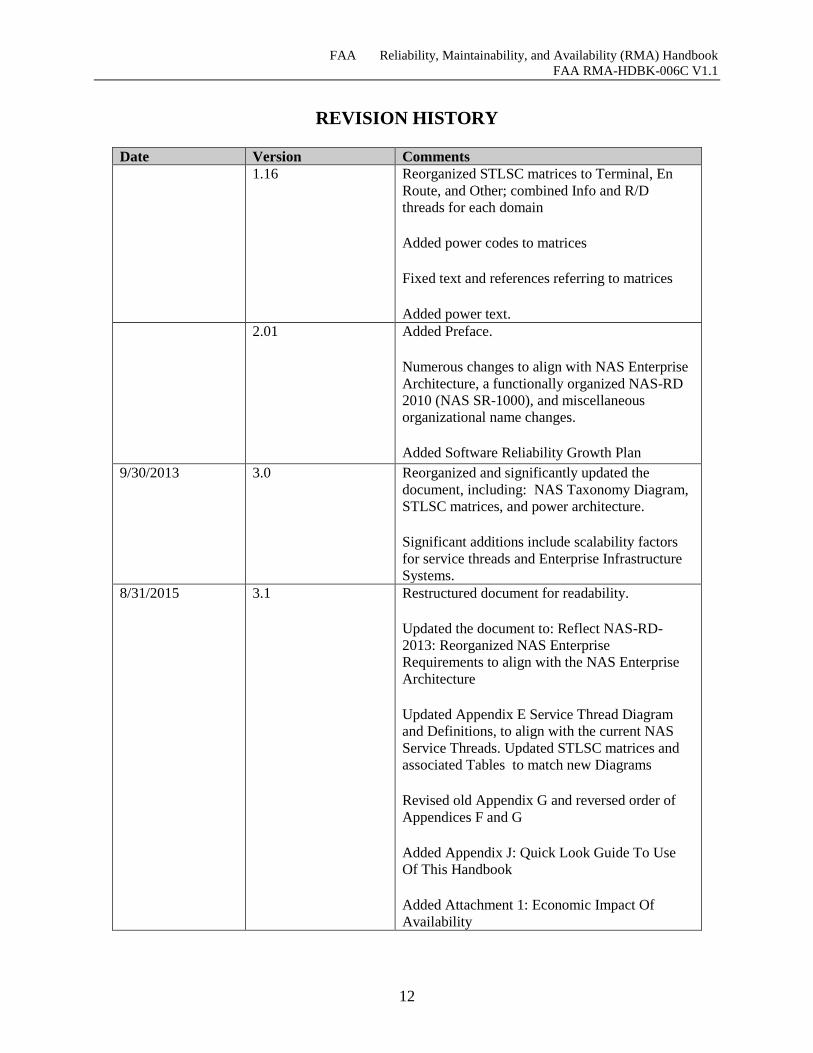
REVISION HISTORY
Date Version Comments
1.16 Reorganized STLSC matrices to Terminal, En
Route, and Other; combined Info and R/D
threads for each domain
Added power codes to matrices
Fixed text and references referring to matrices
Added power text.
2.01
Added Preface.
Numerous changes to align with NAS Enterprise
Architecture, a functionally organized NAS-RD
2010 (NAS SR-1000), and miscellaneous
organizational name changes.
Added Software Reliability Growth Plan
9/30/2013 3.0 Reorganized and significantly updated the
document, including: NAS Taxonomy Diagram,
STLSC matrices, and power architecture.
Significant additions include scalability factors
for service threads and Enterprise Infrastructure
Systems.
8/31/2015 3.1 Restructured document for readability.
Updated the document to: Reflect NAS-RD-
2013: Reorganized NAS Enterprise
Requirements to align with the NAS Enterprise
Architecture
Updated Appendix E Service Thread Diagram
and Definitions, to align with the current NAS
Service Threads. Updated STLSC matrices and
associated Tables to match new Diagrams
Revised old Appendix G and reversed order of
Appendices F and G
Added Appendix J: Quick Look Guide To Use
Of This Handbook
Added Attachment 1: Economic Impact Of
Availability
FAA Reliability, Maintainability, and Availability (RMA) Handbook
FAA RMA-HDBK-006C V1.1
13
PREFACE
The tools and techniques that are the foundation for reliability management were developed in
the late 1950’s and early 1960’s. In that timeframe, the pressures of the cold war and the space
race led to increasing complexity of electronic equipment, which in turn created reliability
problems that were exacerbated by the use of these “equipment” in missile and space
applications that did not permit repair of failed hardware.
Development of this Reliability, Maintainability, and Availability (RMA) Handbook was
undertaken in recognition that changes that have occurred over the past four decades to
traditional approaches to RMA specification and verification have created a need for a dramatic
change in the way these RMA issues are addressed.
The Handbook has been updated to align with the National Airspace System (NAS) Enterprise
Architecture (NAS EA) and support significant changes to the System Effectiveness and RMA
Requirements in the latest version of the NAS Requirements Document, the NAS-RD-2013.
Users of this Handbook should check for newer editions of the NAS-RD prior to applying the
techniques and processes described here to specific NAS requirements. The NAS-Level
requirements are published on the NAS EA portal. This Handbook uses the NAS EA
terminology throughout and differentiates “overloaded” terms that have one definition in the
context of the NAS EA and different definitions elsewhere in the Federal Aviation
Administration (FAA).
The Handbook also includes an appendix (Appendix J) to provide a “quick start” guide for
individuals who are time constrained or do not require the full level of detail provided by the
handbook.
The traditional RMA approach discussed above is not suitable for modern automation systems.
Appendix F outlines how technology advanced, characteristics of the systems changed, and the
severity of the applications increased over the last 40 years. It outlines several areas in which
evolving changes have affected the way the FAA has traditionally viewed RMA requirements in
a legalistic sense i.e., the requirements have been part of legally binding contracts with which
contractors must comply. These changes have degraded the Government’s ability to write and
manage RMA requirements that satisfy the following three (out of ten) characteristics of good
requirements cited in the FAA’s System Engineering Manual (SEM):
Allocable
Attainable (achievable or feasible)
Verifiable
This Handbook describes a new approach to RMA requirements management that focuses on
associating NAS-Level requirements with service threads and assigning each service thread
requirements that are achievable, verifiable, and consistent with the severity of the service
provided to users and specialists. The focus of the RMA management approach is on early
identification and mitigation of technical risks affecting the performance of fault-tolerant
systems, followed by an aggressive software reliability growth program to provide contractual
incentives to find and remove latent software defects.
FAA Reliability, Maintainability, and Availability (RMA) Handbook
FAA RMA-HDBK-006C V1.1
14
This Handbook serves as guidance for systems engineers, architects and developers who are
defining RMA requirements for FAA acquisitions or are implementing systems in response to
such requirements. The Handbook presents users with information about RMA practices and
provides a reference to assist users with developing realistic RMA requirements for hardware
and software or understanding such requirements in the FAA context.
This Handbook is for guidance only and cannot be cited as a requirement.
This Handbook defines a process for allocating NAS-Enterprise-Level RMA requirements to
FAA systems. Doing so facilitates the standardization of requirements across procured systems,
and promotes a common understanding among the FAA community and its affiliates. This
Handbook also describes the evolution of the FAA’s RMA paradigm to foster stakeholder
understanding of the rationale that forms the basis for the guidance provided.
The breadth and scope of system acquisitions or implementations is wide, ranging from major
new system acquisitions to direct one-for-one replacement of existing systems. This broad range
does not lend itself to a one-size-fits-all RMA requirements management
approach/methodology/process. Major new system acquisitions encompass the entire
acquisition life-cycle and are the focus of this Handbook. It is incumbent on stakeholders to
consider the scope of the program/project under consideration and tailor the process prior to
applying the techniques and processes described herein. Doing so requires early involvement
and concurrence by appropriate stakeholders (e.g., ANG and AJW) and subject matter experts
(SME) to ensure operationally acceptable RMA characteristics in fielded systems.
The primary purpose of defining NAS Enterprise-Level RMA requirements is to relate NAS
system-level functional requirements to verifiable specifications for the hardware and software
systems that implement them and to establish a baseline for the requirements.
The processes used in this Handbook are based on the concept of the service thread – strings of
systems and functions necessary to deliver that service, e.g., separation assurance. These service
threads are derived from National Airspace Performance Reporting System (NAPRS)
“Services”. Service threads bridge the gap between un-allocated functional requirements and the
specifications of the systems that support them. Service threads also provide a vehicle for
allocating NAS Enterprise-Level RMA-related requirements to specifications for the
systems/functions that comprise the service threads.
Since the first version of the RMA Handbook was issued, the NAS System Requirements
Specification (NAS-SR-1000) was reorganized and reissued with a functional alignment (NAS-
SR-1000 Version B) and more recently rewritten to align with the NAS EA. In NAS-RD-2013,
individual functional requirements are each assigned a Service Thread Loss Severity Category
(STLSC—pronounced “Still See”) of Safety-critical, Efficiency-Critical, Essential, or Routine.
Service threads are categorized by the consequences of their loss on NAS operations due to the
time-critical nature of their support to maintaining the safe and orderly flow of air traffic
Associating a STLSC with functional requirements is appropriate as it identifies the level of
service thread that should be used to support or implement that requirement. This process is
analogous to the NAS EA Operational Activity to Systems Function Traceability Matrix (SV-5)
mapping of the relationship between the operational activities and the systems and functions
that support them.
This version of handbook provides new material on the following subjects:
FAA Reliability, Maintainability, and Availability (RMA) Handbook
FAA RMA-HDBK-006C V1.1
15
HW/SW Availability Requirements
Software Reliability Growth Program
Reliability, Maintainability, Availability, Logistics, and Life Cycle Cost
HW/SW Availability Requirements
Service thread and/or system-level (hardware and software) availability requirements have been
eliminated. In their place, stringent recovery time requirements and a well-constructed software
reliability growth program are recommended.
Statistical limitations make accurate prediction, demonstration or verification of the high levels
of service thread or system operational availability required for air traffic applications
impossible to substantiate. Establishing “requirements” for which compliance cannot be verified
violates a key premise of the FAA System Engineering Manual (SEM) guidelines for good
requirements and diverts resources from the real issues affecting the operational availability of
automation functions.
For hardware, only inherent availability should only be used to drive the hardware architecture;
however, the reliability of modern processors is such that using inherent availability to
determine redundancy requirements is virtually unnecessary. For software-intensive automation
systems the most significant RMA design driver is the required recovery time from hardware
and software failures, not inherent availability requirements. The required recovery time drives
the fault-tolerant design, the need for redundant hardware and software, timing budgets, and
monitoring overhead constraints. Recovery time requirements for Safety-Critical or Efficiency-
Critical Service Threads require redundant processing necessitating high inherent availability.
Availability requirements should never be applied to software. In place of availability
requirements, software reliability growth programs should be required (refer to Appendix F) to
track the quality and maturity of the software. The primary factor affecting service thread and/or
system-level reliability is software. Software reliability is not a static characteristic, but changes
over time as latent software defects are discovered and corrected. At the NAS EA level, it is
appropriate to identify the system architecture requirements that are necessary to provide a
foundation that is capable of meeting the operational availability needs for each STLSC. This
includes establishing automatic recovery time requirements and requiring one or more
independent backup service threads for Safety-Critical Service Threads. Achieving software
reliability, however, requires an effective reliability growth program, and the RMA Handbook
now includes an improved and more detailed description of how to structure a reliability growth
program and sample templates for use in preparing the Statement of Work in Appendix G.
FAA Reliability, Maintainability, and Availability (RMA) Handbook
FAA RMA-HDBK-006C V1.1
16
Software Reliability Growth Program
The software reliability growth section of Appendix G has been expanded in recognition of the
increased emphasis on the importance of this activity in developing automation systems with
acceptable reliability and recovery time characteristics.
The focus of the software reliability growth program is shifted from Mean Time Between
Failure (MTBF)-centered metrics to Problem Report-centered metrics. The objective is to
provide incentives for contractors to aggressively find and correct defects in the software.
The concept of establishing top-level MTBF decision thresholds for the first site and final site
has been abandoned. Decisions concerning when the system is stable enough to send to the field
and when it has met Operational Readiness Demonstration (ORD) criteria should be made
jointly by the judgment of program management personnel and operational personnel, based on
the frequency of interruptions, their duration, and their effect on user confidence in the system.
It is not realistic to establish inflexible NAS system-level criteria.
Reliability, Maintainability, Availability, Logistics, and Life Cycle Cost
The RMA requirements for the hardware elements comprising service threads are best
determined by acquisition managers, based on the unique circumstances of a particular
application, not a “top-down” mathematical allocation of a system-level requirement.
Hardware RMA requirements need to consider factors such as the availability of Commercial-
off-the-shelf (COTS) products, location of maintenance personnel, staffing, logistics support
policies, level of repair, etc. Clearly, RMA issues for hardware located in a major facility with
24/7 maintenance staffing will differ from those for hardware located on a remote mountain top.
Whether to provide a remotely activated spare should be driven by Life Cycle Cost (LCC)
considerations, not the allocation of an arbitrary system-level requirement. In a few sections of
this Handbook, this revision has added some minor discussion of LCC issues to be considered
by acquisition managers when establishing RMA characteristics for hardware components.
FAA Reliability, Maintainability, and Availability (RMA) Handbook
FAA RMA-HDBK-006C V1.1
17
SCOPE
THIS HANDBOOK IS FOR GUIDANCE ONLY AND CANNOT BE CITED AS A REQUIREMENT
This Handbook is intended to serve as guidance for systems engineers, architects and
developers who are defining Reliability, Maintainability and Availability (RMA) requirements
for Federal Aviation Administration (FAA) acquisitions or are implementing systems in
response to such requirements. It is also intended as an information source for the broader user
community e.g., Technical Operations personnel. It applies equally to new acquisition and
established, iterative development programs. The Handbook presents users with information on
a new approach to RMA requirements management and provides a reference to assist users with
developing realistic RMA requirements for hardware and software or understanding such
requirements in the FAA context.
Appendix J provides a ”quick-start” guide to make the handbook methodology available to
individuals who are time constrained or do not require the full level of detail provided by the
handbook.
This Handbook describes the evolution of the FAA’s RMA paradigm as the basis for
understanding the new approach and defines a process, to be used as guidance, for allocating
National Airspace System (NAS) Enterprise-Level RMA requirements to FAA systems and
documents. Doing so facilitates the standardization of requirements across procured systems,
and promotes a common understanding among the FAA stakeholder community.
The primary purpose of defining NAS Enterprise-Level RMA requirements is to relate NAS
system-level functional requirements to verifiable specifications for the hardware and software
systems that implement them and to establish a baseline for the requirements.
This document addresses RMA considerations associated with four general categories of NAS
systems:
1. Automated information systems that continuously integrate and update data from
remote sources to provide timely decision-support services to Air Traffic Control
(ATC) specialists (Section 7.7.1 and 8.1.1.1)
2. Remote/Distributed and Standalone Systems that provide services such as
navigation, surveillance, and communications to support NAS ATC systems
(Section 7.7.2 and 8.1.1.2)
3. Infrastructure systems (Section 7.7.3) that provide services such as power (Section
8.1.1.4.1), Heating, Ventilating, and Air Conditioning (HVAC) systems (Section
8.1.1.4.2), and communications transport (Section 8.1.1.4.3) in support of NAS
facilities. Enterprise Infrastructure Systems (EIS) which host multiple services
across NAS facilities (Section 8.1.1.4.4).
4. Mission support systems that assist in the design of NAS airspace and the utilization
of the electromagnetic spectrum (Section 8.1.1.3)
This document presents guidance on the treatment of RMA considerations for each category of
system and is intended for use by acquisition managers and their staffs in the preparation,
conduct and execution of FAA procurements.
FAA Reliability, Maintainability, and Availability (RMA) Handbook
FAA RMA-HDBK-006C V1.1
18
This revision of the Handbook expands the scope of RMA analysis to include “Right-sizing”
analysis. Today, NAS requirements are assigned to one of four availability categories based on
the criticality of the service the requirement supports, as defined in Section 4, these are:
Safety-Critical
Efficiency-Critical
Essential
Routine
Currently, there is no method for clearly delineating between Efficiency-Critical and Essential
NAS services. Some NAS level requirements have been considered overly restrictive in
designating NAS services as Efficiency-Critical for the entire NAS. This impacts current FAA
initiatives to “Right-Size” the NAS1. ANG-B has studied the impact of Availability on airline
and passenger economic costs, using facility operations and propagated delay as metrics. This
study is presented in Attachment 1, which may serve as the basis for a technique for delineating
the Efficiency-Critical / Essential boundary on a facility basis for individual systems or
programs. There may be no impact on overall NAS efficiency due to loss of “efficiency critical”
services in a low capacity region of airspace.
Where legacy systems are involved with no clear successor or replacement program or system,
the NAS EA staff should regularly assess the RMA characteristics of legacy systems, and
identify shortfalls, and identify issues.
1 Federal Aviation Administration Strategic Initiatives 2014-2018
FAA Reliability, Maintainability, and Availability (RMA) Handbook
FAA RMA-HDBK-006C V1.1
19
DOCUMENT OVERVIEW
This Handbook covers three major topics. The first, addressed in Section 5 describes a new
RMA requirements management approach focused on identifying and mitigating technical risks
affecting the performance of fault-tolerant systems, followed by an aggressive software
reliability growth program to provide contractual incentives to find and remove latent software
defects.
The second major topic, contained in Section 6, describes how the NAS-Level RMA
requirements were developed. This material is included to provide the background information
necessary to develop an understanding of the RMA requirements management approach.
The third major topic, contained in Section 7, addresses the specific tasks to be performed by
service units, acquisition managers, and their technical support personnel to apply the NAS-
Level requirements to major system acquisitions. The section is organized in the order of a
typical procurement action. It provides a detailed discussion of specific RMA activities
associated with the development of a procurement package and continues throughout the
acquisition cycle until the system has successfully been deployed. The approach is designed to
help ensure that the specified RMA characteristics are actually realized in fielded systems.
The elements of this approach are summarized below:
Section 6: RMA Requirements Management Approach
This Handbook describes a new approach to RMA requirements management that focuses on
associating NAS-Level requirements with service threads and assigning each service thread
requirements that are achievable, verifiable, and consistent with the severity of the service
provided to users and specialists. The focus of the RMA management approach is on early
identification and mitigation of technical risks affecting the performance of fault-tolerant
systems, followed by an aggressive software reliability growth program to provide contractual
incentives to find and remove latent software defects. The reader is encouraged to refer to
Appendix F as it provides context and rationale for the guidance provided herein.
The key elements of the approach are:
Map the NAS-Level functional requirements to a set of generic service threads based on the
NAPRS services reported for deployed systems. (Section 6)
Assign Service Thread Loss Severity Categories (STLSC) of “Safety-Critical,” “Efficiency-
Critical,” “Essential,” " Routine," and "Remote/Distributed," to the service threads based on the
effect of the loss of the service thread on NAS safety and efficiency of operations. (Sections 6
and 7.3)
Distinguish between Efficiency-Critical threads whose interruptions can be safely
managed by reducing capacity that may, however, cause significant traffic disruption
vs. Safety-Critical threads whose interruption could present a significant safety
hazard during the transition to reduced capacity operations. (Sections 6 and 7.3)
Allocate NAS-Level availability requirements to service threads based on the
severity and associated availability requirements of the NAS capabilities supported
by the threads.
Recognize that the probability of achieving the availability requirements for any
service thread identified as Safety-Critical is unacceptably low; therefore, where
FAA Reliability, Maintainability, and Availability (RMA) Handbook
FAA RMA-HDBK-006C V1.1
20
possible, decompose the thread into alternate (at least two) independent new threads,
each with a STLSC no greater than “Efficiency-Critical.”
Recognize that the availability requirements associated with “Efficiency-Critical”
service threads will require redundancy and fault tolerance to mask the effect of
software failures.
Move from using availability as a contractual requirement to parameters such as
MTBF, Mean Time To Restore (MTTR) recovery times, and mean time between
successful recoveries that are verifiable requirements. Couple these with an
aggressive software reliability growth program.
Use RMA models only as a rough order of magnitude confirmation of the potential
of the proposed hardware configuration to achieve the inherent availability of the
hardware, not a prediction of operational reliability.
Focus RMA effort, during development, on design review and risk reduction testing
activities to identify and resolve problem areas that could prevent the system from
approaching its theoretical potential.
Recognize that “pass/fail” reliability qualification tests are impractical for systems
with high reliability requirements and substitute an aggressive software reliability
growth program.
Use NAPRS data from the National Airspace System Performance Analysis System
(NASPAS) to provide feedback on the RMA performance of currently fielded
systems to assess the reasonableness and attainability of new requirements, and to
verify that the requirements for new systems will result in systems with RMA
characteristics that are at least as good as those of the systems they replace.
Apply these principles throughout the acquisition process.
The application of these RMA management methods for the new approach is
discussed in detail in Section 8. These methods apply equally to new acquisitions
and established iterative development programs. All phases of the acquisition
process are addressed, including preliminary requirements analysis, allocation,
preparation of procurement documents, proposal evaluation, contractor monitoring,
and design qualification and acceptance testing.
Throughout all phases of design and allocation, appropriately chosen subject matter
experts (SME) should be utilized to ensure successful incorporation of an
operational viewpoint into the requirements. SMEs can be both operational Air
Traffic Control personnel from appropriate facility types and locations as well as
technical operations and maintenance personnel with insight into maintainability and
repair aspects of systems to be fielded. Early involvement of SMEs during
procurement will help to ensure both clarification of the expected role and utility of a
future system, and help set operational expectations for future systems. SME input
should be carefully documented and weighed against NAS EA functional
expectations for a system and where necessary, fed back into the concept of
operations (CONOPS).
Section 7: Derivation of NAS-Level RMA Requirements
This section introduces the concept of a service thread. This section documents the procedures
used to map NAS Architecture functional requirements to generic service threads to serve as the
FAA Reliability, Maintainability, and Availability (RMA) Handbook
FAA RMA-HDBK-006C V1.1
21
basis for allocating the requirements to specific systems. Section 7.7.3 provides guidance for
allocating NAS-Level requirements to Enterprise Infrastructure Systems (EIS).
Section 8: Acquisition Strategies and Guidance
This section describes the specific tasks to be performed by technical staffs of FAA Service
Units and acquisition managers to apply the NAS-Level requirements to system level
specifications and provides guidance and examples for the preparation of RMA portions of the
procurement package to include:
Preliminary Requirements Analysis
Procurement Package Preparation
System Specification Document (SSD)
Statement of Work (SOW)
Information for Proposal Preparation (IFPP)
Proposal Evaluation
Reliability, Maintainability and Availability Modeling and Assessment
Fault-Tolerant Design Evaluation
Contractor Design Monitoring
Formal Design Reviews
Technical Interchange Meetings
Risk Management
Design Validation and Acceptance Testing
Fault Tolerance Diagnostic Testing
Section 9: SERVICE THREAD MANAGEMENT
This section describes the process for updating the service thread database to maintain
consistency with the NAPRS services in response to the introduction of new services, system
deployments, modifications to NAPRS services, etc.
Section 10: RMA REQUIREMENTS ASSESSMENT
Describes the approach used to compare new requirements with the performance of fielded
systems to verify the achievability of proposed requirements, ensure that the reliability of new
systems will be at least as good as that of existing systems, and to identify deficiencies in the
performance of currently fielded systems.
FAA Reliability, Maintainability, and Availability (RMA) Handbook
FAA RMA-HDBK-006C V1.1
22
APPLICABLE DOCUMENTS
Documents referenced in this Section are versions current as of the revision of this document.
Readers are urged to check for and utilize the most current versions of these documents.
3.1 Specifications, standards, and handbooks FEDERAL AVIATION ADMINISTRATION
FAA-G-2100H, ELECTRONIC EQUIPMENT, GENERAL REQUIREMENTS, 9 May 2005
FAA-STD-067, FAA Standard Practice for Preparation of Specifications, 4 December 2009.
FAA System Engineering Manual, Version 3.1, 11 October 2006.
NAS-RD-2013, National Airspace System Requirements Document 2013, Baseline, 11 August
2014.
NAS-SR-1000, FAA System Requirements, 21 March 1985.
NAS Enterprise Architecture Portal. Version 8.2, 9 January 2014.
DEPARTMENT OF DEFENSE
MIL-HDBK-217F, Reliability Prediction of Electronic Equipment, 2 December 1991.
MIL-HDBK-472, Maintainability Prediction, Notice 1, 12 January 1984.
MIL-HDBK-781A, Reliability Test Methods, Plans, and Environments for Engineering,
Development, Qualification, and Production, April 1996.
MIL-STD-471A, Maintainability Verification/Demonstration/Evaluation, 27 March 1973.
MIL-STD-882E, Department of Defense Standard Practice for System Safety, 11 May 2012.
MIL-STD-967, Department of Defense Standard Practice, Defense Handbooks Format and
Content, 1 August 2003.
3.2 FAA Orders FAA Order JO 6040.15, National Airspace Reporting System (NAPRS)
FAA Order 6000.36A, Communications Diversity, 11/14/95
DRAFT FAA Order 6000.36B, Communications Diversity
FAA Order 6000.5D - Facility, Service, and Equipment Profile (FSEP)
FAA Order 6000.15G - General Maintenance Handbook for National Airspace System (NAS)
Facilities
FAA Order 6950.2D, Electrical Power Policy Implementation at National Airspace System
Facilities, 10/16/03.
3.3 Non-Government Publications IEEE J-STD-016, Standard for Information Technology Software Life Cycle Processes
FAA Reliability, Maintainability, and Availability (RMA) Handbook
FAA RMA-HDBK-006C V1.1
23
DEFINITIONS
This section provides definitions of RMA terms. Three basic categories of definitions are
presented in this section:
1. Definitions of commonly used RMA terms and effectiveness measures
2. Definitions of RMA effectiveness measures tailored to address unique characteristics
of FAA fault-tolerant automation systems
3. Definitions of unique terms used both in this document and in the RMA section of
NAS-RD-2013
Definitions for commonly used RMA effectiveness terms are based on those provided in MIL-
STD-721. In some cases, where multiple definitions exist, the standard definitions have been
modified or expanded to provide additional clarity or resolve inconsistencies. Less frequently
used terms are defined in Appendix I.2.
For unique terms created during the preparation of the document and the RMA section of the
NAS-RD-2013, a brief definition is included along with a pointer to the section of the
Handbook where the detailed rationale is provided. This document assumes the reader is
familiar with the NAS Enterprise Architecture (NAS EA) (Version 8.0 or greater) and its
associated terminology. Readers unfamiliar with the NAS EA are referred to the website:
nasea.faa.gov.
AVAILABILITY: The probability that a system or constituent piece may be operational
during any randomly selected instant of time or, alternatively, the fraction of the total available
operating time that the systems or constituent piece is operational. Measured as a probability,
availability may be defined in several ways, which allows a variety of issues to be addressed
appropriately, including (see Figure 4-1):
Operational Availability (AOp): AOp is the ratio of total operating facility/service hours
to maximum facility/service hours, expressed as a percentage. It is the Local or
Enterprise NAS availability that is needed to support ATC operations.
Human Availability (AH): The availability of the effect a human has on the operational
availability of the NAS Service. This includes the availability of operators to provide the
NAS Service and includes the availability of personnel to maintain system availability.
Service Availability (AS): The availability of the services including both the hardware
and software components. This may include multiple systems, communications links
and facilities required to provide that service. This service availability includes
scheduled and unscheduled service outages during hours of operation.
Facility Availability (AF): The availability of a facility providing or necessary to
provide service(s). It consists of the availability of the facility infrastructure components
(i.e. power, HVAC, etc.).
Communication Availability (AC): The availability related to the communications
interchange between facilities and systems required to deliver services.
System Availability (ASY): The availability of a particular piece of equipment or system
(at the “system-level”). System Availability is comprised of Inherent Availability of the
system hardware and Software Availability). This includes the availability of the system,
as installed, as well as the availability of equipment, components and tools required to
maintain the system and keep it operational.
FAA Reliability, Maintainability, and Availability (RMA) Handbook
FAA RMA-HDBK-006C V1.1
24
Inherent Availability (AI): The probability that a particular piece of equipment or
system will operate satisfactorily at a given point in time when used under stated
conditions in an ideal support environment. It excludes software availability (ASW),
logistics time, waiting or administrative downtime, and preventive maintenance
downtime. It includes corrective maintenance downtime. Inherent availability is
generally derived from analysis of an engineering design and is based on quantities
under control of the designer. For FAA systems, ANG regards firmware as a component
of hardware. Failures attributed to firmware should be treated as hardware failures.
Similarly, firmware updates should be treated as hardware revisions.
Software Availability (ASW): The availability of the software components independent
of the hardware.
Information Availability (AInfo): The accessibility and usability of information to end-
users and systems.
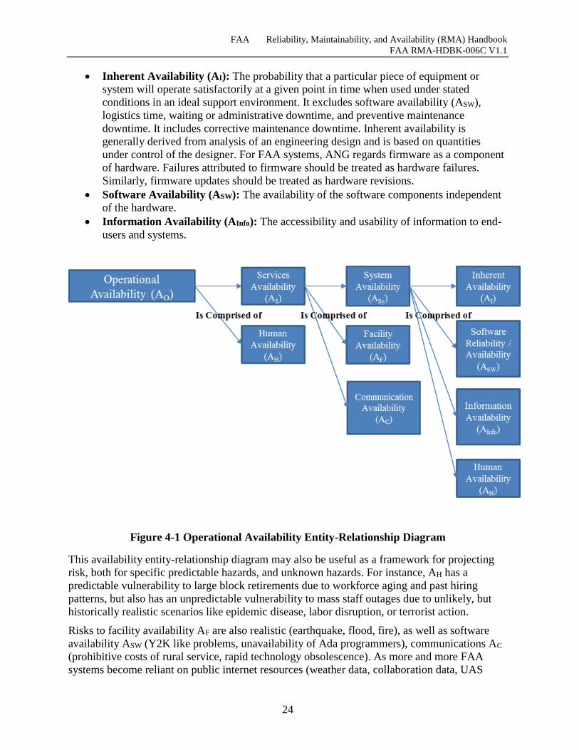
Figure 4-1 Operational Availability Entity-Relationship Diagram
This availability entity-relationship diagram may also be useful as a framework for projecting
risk, both for specific predictable hazards, and unknown hazards. For instance, AH has a
predictable vulnerability to large block retirements due to workforce aging and past hiring
patterns, but also has an unpredictable vulnerability to mass staff outages due to unlikely, but
historically realistic scenarios like epidemic disease, labor disruption, or terrorist action.
Risks to facility availability AF are also realistic (earthquake, flood, fire), as well as software
availability ASW (Y2K like problems, unavailability of Ada programmers), communications AC
(prohibitive costs of rural service, rapid technology obsolescence). As more and more FAA
systems become reliant on public internet resources (weather data, collaboration data, UAS
FAA Reliability, Maintainability, and Availability (RMA) Handbook
FAA RMA-HDBK-006C V1.1
25
operator connectivity) AInfo will become increasingly vulnerable both to routine Internet
availability problems (backhoe), and to major disruption ranging from just-because-we-can
denial of service attacks to nation state actions against critical infrastructure.
The advantage of characterizing risk in this manner is that these risks can then be fed into
service availability prediction, which can then feed analysis of alternatives.
CERTIFICATION: A quality control method used by FAA Technical Operations Services
(TechOps) to ensure NAS systems and services are performing as expected. TechOps
determines certification requirements. TechOps is authorized to render an independent
discretionary judgment about the provision of advertised services. Also because of the need to
separate profit motivations from operational decisions and the desire to minimize liability,
certification and oversight of the NAS are inherently governmental functions. [FAA Order
6000.30, Definitions Para 11.d]
COVERAGE: Probability of successful recovery from a failure given that a failure occurred.
FACILITY: Generally, any installation of equipment designated to aid in the navigation,
communication, surveillance, or control of air traffic. Specifically, the term denotes the total
electronic equipment, power generation, or distribution systems and any structure used to house,
support, and/or protect the use of equipment and systems. A facility may include a number of
systems, subsystems, or equipment.
FAILURE: The event or inoperable state in which any item or part of an item does not, or
would not perform as specified.
Dependent Failure: A failure caused by the failure of an associated item(s), e.g. failure
of a computer due to loss of external power.
Independent Failure: A failure that is not caused by the failure of any other item, e.g.,
failure of a computer due to failure of its internal power supply.
FAILURE MODE AND EFFECTS ANALYSIS (FMEA): A procedure for analyzing each
potential failure mode in a system to determine its overall results or effects on the system and to
classify each potential failure mode according to its severity.
FAILURE RATE: The total number of failures within an item population, divided by the total
number of operating hours.
FAULT TOLERANCE: Fault tolerance is an attribute of a system that is capable of
automatically detecting, isolating, and recovering from unexpected hardware or software
failures.
INDEPENDENT ALTERNATE SERVICE THREADS: Independent alternate service
threads entail at least two service threads composed of separate system components that provide
alternate data paths. They provide levels of reliability and availability that cannot be achieved
with a single service thread.
Ideally, alternate threads should not share a single power source. If alternate threads do share a
single power source, the power source must be designed, or the power system topology must be
configured, to minimize failures that could cause multiple threads to fail. The independent
alternate threads may share displays, provided adequate redundant displays are provided to
permit the specialist to relocate to an alternate display in the event of a display failure.
FAA Reliability, Maintainability, and Availability (RMA) Handbook
FAA RMA-HDBK-006C V1.1
26
Independent Alternate Service Threads may or may not require diverse hardware and software,
but all threads should be active and available at all times. Users need to be able to select either
thread at will without need for a system switchover (See Section 6.3 for a detailed discussion of
Independent Alternate Service Threads.)
INHERENT VALUE: A measure of reliability, maintainability, or availability that includes
only the effects of an item’s hardware design and its application, and assumes an ideal operation
and support environment functioning with perfect software.
LOWEST REPLACEABLE UNIT (LRU): For restoration purposes, an LRU is an assembly,
printed circuit board, or chassis-mounted component that can easily be removed and replaced.
MAINTAINABILITY: The measure of the ability of an item to be retained in or restored to
specified condition through maintenance performed, at each prescribed level of maintenance
and repair, by appropriately skilled personnel using prescribed procedures and resources.
Many maintainability effectiveness measures have inconsistent and conflicting definitions, and
the same acronym sometimes represents more than one measure. These inconsistencies
generally arise as a consequence of the categories of downtime that are included in a
maintainability effectiveness measure.2 The following definitions reflect the usage in this
document and the NAS-RD-2013:
Maintenance Significant Items (MSI) – Hardware elements that are difficult to
replace, i.e., cables, backplanes, and antennas.
Mean Down Time (MDT) – Mean Down Time is an operational performance measure
that includes all sources of system downtime, including corrective maintenance,
preventive maintenance, travel time, administrative delays, and logistics supply time.
Mean Time to Repair (MTTR) – Mean Time to Repair is a basic measure of
maintainability. It is the sum of corrective maintenance times (required at any specific
level of repair) divided by the total number of failures experienced by an item that is
prepared at that level, during a particular interval, and under stated conditions. The
MTTR is an inherent design characteristic of the equipment. Traditionally, this
characteristic represents an average of the number of times needed to diagnose, remove,
and replace failed hardware components. In effect, it is a measure of the extent to which
physical characteristics of the equipment facilitate access to failed components in
combination with the effectiveness of diagnostics and built in test equipment.3
MTTR is predicted by inserting a broad range of failed components and measuring the
times to diagnose and replace them. It is calculated by statistically combining the
component failure rates and the measured repair times for each component. The measure
assumes an ideal support environment in which trained technicians with all necessary
tools and spare parts are immediately available – but it does not include scheduled
downtime for preventive maintenance or such things as the time needed for a technician
to arrive on scene or delays in obtaining necessary spare parts.
2 Maintenance events performed by FAA personnel are defined as any activity performed including scheduled and
unscheduled events. For the purposes of this Handbook, scheduled maintenance events are assumed to not impact
on Availability, and are excluded from availability calculations.
FAA Reliability, Maintainability, and Availability (RMA) Handbook
FAA RMA-HDBK-006C V1.1
27
Mean Time to Repair is a metric that is commonly used in procurement of systems or
components where the contractor is held responsible for design and manufacturing
aspects of Maintainability, but is not (or cannot be) held responsible for performing the
repair or maintaining the logistics system. In specifying this MTTR, systems engineers
should consult with TechOps on what proportion of the NAS-RD specified MTTR
(Restore) can be allocated to the Repair. Figure 4-2 Failure / Restoration Timeline
illustrates the sequence of events in failure, repair and restoration of service.
MTTR (NAS-RD Definition)
The current NAS-RD-2013 uses the acronym MTTR to mean Mean Time to Restore,
e.g. “3.3.1.2.0-5 The MTTR for non-routine service thread components shall be less than
or equal to 0.5 hours.”
NAS-RD Mean Time to Restore is commonly understood to exclude travel time and time
to obtain parts not stored on site, but to include a FAA specific process of re-
certification of the failed system prior to notification of availability to the operational
users.
Mean Time to Restore Service (MTTRS) – The MTTRS is also an inherent measure
of the design characteristics of complex systems. It represents the time needed to
manually restore service following an unscheduled service failure requiring manual
intervention. Like MTTR, it includes only unscheduled downtime and assumes an ideal
support environment, but the MTTRS includes not only the time for hardware
replacements, but also times for software reloading and system restart times. MTTRS
does not include the time for the successful operation of automatic fault detection and
recovery mechanisms that may be part of the system design. The performance
specifications for the operation of automatic recovery mechanisms are addressed
separately.
MTTRS may be a suitable quality metric for services provided by a contractor on a
leased basis. In general leased services are provided on a per location or item (circuit
etc.) basis, caution should be exercised in developing MTTRS numbers for aggregated
locations or items. In such circumstances a Maximum Time to Restore Service should
also be specified on a per item basis.
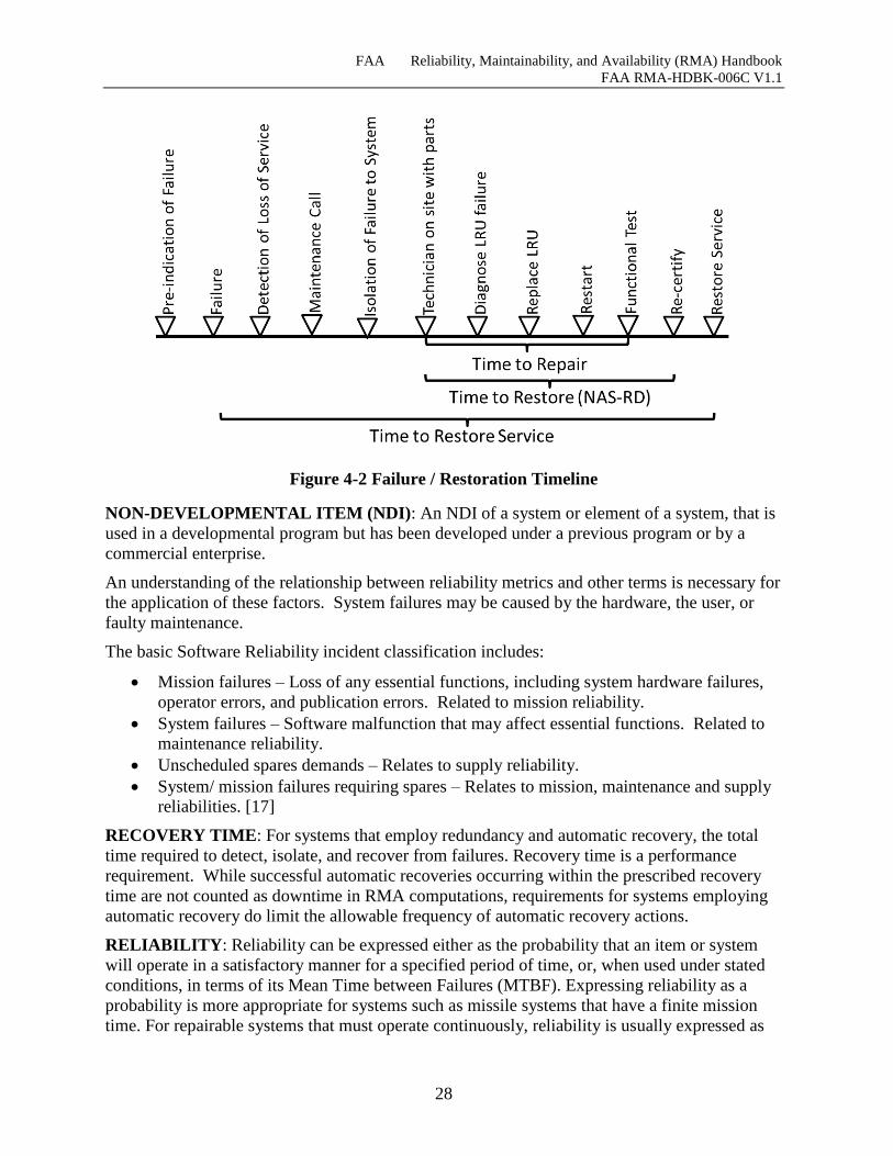
FAA Reliability, Maintainability, and Availability (RMA) Handbook
FAA RMA-HDBK-006C V1.1
28
Figure 4-2 Failure / Restoration Timeline
NON-DEVELOPMENTAL ITEM (NDI): An NDI of a system or element of a system, that is
used in a developmental program but has been developed under a previous program or by a
commercial enterprise.
An understanding of the relationship between reliability metrics and other terms is necessary for
the application of these factors. System failures may be caused by the hardware, the user, or
faulty maintenance.
The basic Software Reliability incident classification includes:
Mission failures – Loss of any essential functions, including system hardware failures,
operator errors, and publication errors. Related to mission reliability.
System failures – Software malfunction that may affect essential functions. Related to
maintenance reliability.
Unscheduled spares demands – Relates to supply reliability.
System/ mission failures requiring spares – Relates to mission, maintenance and supply
reliabilities. [17]
RECOVERY TIME: For systems that employ redundancy and automatic recovery, the total
time required to detect, isolate, and recover from failures. Recovery time is a performance
requirement. While successful automatic recoveries occurring within the prescribed recovery
time are not counted as downtime in RMA computations, requirements for systems employing
automatic recovery do limit the allowable frequency of automatic recovery actions.
RELIABILITY: Reliability can be expressed either as the probability that an item or system
will operate in a satisfactory manner for a specified period of time, or, when used under stated
conditions, in terms of its Mean Time between Failures (MTBF). Expressing reliability as a
probability is more appropriate for systems such as missile systems that have a finite mission
time. For repairable systems that must operate continuously, reliability is usually expressed as
FAA Reliability, Maintainability, and Availability (RMA) Handbook
FAA RMA-HDBK-006C V1.1
29
the probability that a system will perform a required function under specific conditions for a
stated period of time. It is a function of MTBF, according to the formula
where “t” is the mission time and “m” is the MTBF. Also, reliability is often expressed as the
raw MTBF value, in hours, rather than calculating R according to the above formula.
Software reliability metrics are similar to hardware metrics for a repairable system. The data
provided is commonly a series of failure times or other events. The data is used during software
development to measure time between events, analyze the improvement resulting from
removing errors and making decisions about when to release or update a software product
version. Metrics are also used to assess software or system stability. [13]
Mean Time Between Failure (MTBF – MTBF is a basic measure of Reliability. MTBF
is the average time between failures of system components.
Mean Time Between Outage (MTBO) – MTBO is an operational performance
measure for deployed systems that corresponds to the inherent MTBF measure. A
measure of the time between unscheduled interruptions, MTBO is monitored by
NAPRS. It is computed by dividing the total operating hours by the number of outages.
SERVICE: The term “service” has different meanings in the contexts of the NAS Enterprise
Architecture (Version 8.0 or greater) and NAPRS and FSEP.
NAS Enterprise Architecture "Services" are services, such as separation assurance,
provided to NAS users. These services are provided by a combination of ATC
specialists and the systems that support them. Each NAS EA Service is comprised of
one or more NAS-RD functions.
NAPRS / FSEP “Services” as defined in FAA order 6000.5 are services that represent
an end product, which is delivered to a user (air traffic specialists, the aviation public or
military) that results from an appropriate combination of systems, subsystems,
equipment, and facilities. NAPRS provides the guidance on how to report the status of
these services. To distinguish these services from NAS EA Services, NAPRS / FSEP
services will be referred to in this document as “service threads.” In this document these
services will be referred to as NAPRS service threads.
SERVICE-ORIENTED ARCHITECTURE: A software design and software architecture
design pattern based on structured collections of discrete software modules, known as services,
which collectively provide the complete functionality of a large software application.[50]
SERVICE THREADS: Service threads are strings of systems/functions that support one or
more of the NAS EA Functions. These service threads represent specific data paths (e.g. radar
surveillance data) to air traffic specialists or pilots. The threads are defined in terms of
narratives and Reliability Block Diagrams depicting the systems that comprise them. They are
based on the reportable services defined in NAPRS. Note that some new service threads have
been added to the set of NAPRS services, and some of the NAPRS services that are components
of higher-level threads have been removed. (See Section 7 for a detailed discussion of the
service thread concept.)
m
t
eR
FAA Reliability, Maintainability, and Availability (RMA) Handbook
FAA RMA-HDBK-006C V1.1
30
SERVICE THREAD LOSS SEVERITY CATEGORY (STLSC): Each service thread is
assigned a STLSC based on the severity of impact that loss of the thread could have on the safe
and/or efficient operation and control of aircraft. (See Section 7.4 for a detailed discussion of
the STLSC concept.) The Service Thread Loss Severity Categories are:
Safety-Critical - A key service in the protection of human life. Loss of a Safety-Critical
service increases the risk in the loss of human life.
Efficiency-Critical - A key service that is used in present operation of the NAS. Loss of
an Efficiency-Critical Service has a major impact in the present operational capacity.
Essential - A service that if lost would significantly raise the risk associated with
providing efficient NAS operations.
Routine - A service which, if lost, would have a minor impact on the risk associated
with providing safe and efficient NAS operations.
Service threads can also be characterized as Remote/Distributed where loss of a service thread
element, i.e., radar, air/ground communications site, or display console, would incrementally
degrade the overall effectiveness of the service thread but would not render the service thread
inoperable.
The distinction between Efficiency-Critical and Essential services is in the extent of the impact
of the outage on air traffic. Loss of an Efficiency-Critical service would cause significant
disruption of traffic flow affecting multiple facilities across a region of Metroplex or En Route
Center size or larger. Loss of an Essential service would cause significant disruption of traffic
flow within a local area, e.g., a single airport or TRACON. When designing systems providing
Efficiency-Critical service cost/benefit decisions may be required that will call for provision of
lower level (Essential) service at smaller or less critical locations. The techniques described in
Appendix J were developed to aid in developing criteria for making this decision. ANG-B7 can
provide assistance in applying these techniques.
SEVERITY: A relative measure of the consequence of a failure mode, sensitivity to outage
downtime, and its frequency of occurrence.
SOFTWARE RELIABILITY:
The American National Standards Institute (ANSI) and Institute of Electrical and Electronics
Engineers (IEEE) have defined Software Reliability in ANSI/IEEE STD-729-1991 [3] as:
“The probability of failure-free software operation for a specified period of time in a specified
environment”
NASA-STD-8739.8 NASA Software Assurance Standard defines Software Reliability as a
discipline of Software Assurance that:
1. “Defines the requirements for software controlled system fault/failure detection,
isolation, and recovery;
2. Reviews the software development processes and products for software error prevention
and/or reduced functionality states; and,
3. Defines the process for measuring and analyzing defects and defines/derives the
reliability and maintainability factors.”
TARGET OPERATIONAL AVAILABILITY: The desired operational availability
associated with a given NAS Service.
FAA Reliability, Maintainability, and Availability (RMA) Handbook
FAA RMA-HDBK-006C V1.1
31
VALIDATION: The process of confirming a product or work product satisfies or will satisfy
the stakeholders’ needs. It determines a system does everything it should and nothing it should
not do. (i.e., that the system requirements are unambiguous, correct, complete, consistent,
operationally and technically feasible, and verifiable).
VERIFICATION: The process which confirms that the system and its elements meet the
specified requirements; that the system is built as specified.
FAA Reliability, Maintainability, and Availability (RMA) Handbook
FAA RMA-HDBK-006C V1.1
32
PURPOSE AND OBJECTIVES
RMA guidance, methods, and techniques are found across a number of disparate sources e.g.,
FAA Orders, Standards, Handbooks, Specifications, and Non-Government Publications. This
Handbook is a compilation of salient information garnered from these source documents. This
information has been synthesized and formulated into a systematic approach to RMA
requirements management supported by newly established RMA management methods and
tasks.
The Goal: Develop realistic RMA requirements for hardware and software and ensure
that specified RMA characteristics are realized in fielded systems.
The Handbook provides a single concise source to help users gain an understanding of the
subject matter within the context of their discipline. Those needing a deeper understanding of
the subject matter are directed to the referenced documents. The Handbook assists in developing
basic skills in and describes the significance and implications of the new RMA management
approach so existing skills can be applied in a new context.
The purpose of this Handbook is twofold:
1. Introduce a new approach to RMA requirements management that is responsive to
changes in the traditional approach to RMA specification and verification.
2. Provide a reference to assist stakeholders with developing realistic RMA requirements
for hardware and software.
The objective is to facilitate the standardization of requirements across procured systems,
promoting a common understanding among the FAA community and its affiliates.
5.1 Background
The primary purpose of defining NAS Enterprise-Level RMA requirements is to relate NAS
system-level functional requirements to verifiable specifications for the hardware and software
systems that implement them and establish a "floor" for the minimum level of those
requirements. An intermediate step in this process is the introduction of the concept of generic
service threads that define the systems/functions which support the various NAS Services to
controllers and/or pilots. The service threads bridge the gap between un-allocated functional
requirements and the specifications of the systems that support them. They also provide the
vehicle for allocating NAS Enterprise-Level RMA-related4 requirements to specifications for
the systems/functions that comprise the service threads. The NAS-Level requirements on which
this Handbook is based are published on the NAS EA portal. This Handbook uses the NAS EA
portal terminology (Version 8.0 or greater) throughout and differentiates “overloaded” terms
that have one definition in the context of the NAS EA and different definitions elsewhere in the
FAA.
NAS Enterprise Level RMA requirements are provided to satisfy the following objectives:
4 The term “RMA-related requirement(s)” includes, in addition to the standard reliability, maintainability and
availability requirements, other design characteristics that contribute to the overall system reliability and
availability in a more general sense (e.g., fail-over time for redundant systems, frequency of execution of fault
isolation and detection mechanisms, system monitoring and control. on line diagnostics, etc.).
FAA Reliability, Maintainability, and Availability (RMA) Handbook
FAA RMA-HDBK-006C V1.1
33
Provides a means of allocating RMA requirements from FAA CONOPS to program
requirements documents.
Establishes a common framework upon which to justify future additions and deletions of
requirements.
Provides uniformity and consistency of requirements across procured systems,
promoting common understanding among the specifying engineers and the development
contractors.
Establishes and maintains a baseline for validation and improvement of the RMA
characteristics of fielded systems.
Provides a starting point for the scaling of Program-Level RMA requirements based on
the capacity of various facility groups. (Scaling service availability requirements to
facility groups based on size and special local needs are discussed in Section 7.4.1.2).
Provides guidance in Section 7.7.3 for Program-Level RMA requirements related to
Infrastructure Systems such as Power and Enterprise Infrastructure Systems.
Purpose of this Handbook
This Handbook:
1) Introduces RMA requirements management approach that focuses on associating NAS-
Level requirements with service threads and assigning each service thread requirements that
are achievable, verifiable, and consistent with the severity of the service provided to users
and specialists.
2) Provides guidance to stakeholders in the form of a process/tasks to:
Interpret and allocate the NAS-RD-2013 RMA requirements to systems.
Decompose the NAS Enterprise-Level RMA requirements into realistic and achievable
requirements documents and design characteristics.
Establish risk management activities to permit the monitoring of critical fault tolerance
and RMA characteristics during system design and development.
Establish a software reliability growth program to ensure that latent design defects are
systematically exposed and corrected during testing at the contractor’s plant, FAA
testing facilities and subsequent deployment.
Update and maintain the NAS Enterprise-Level RMA requirements definition process.
The RMA Handbook is intended to be a living document. It will be updated periodically to
reflect changes to NAS requirements as well as to incorporate the experience gained from using
techniques described in it and from downstream procurements and implementations.
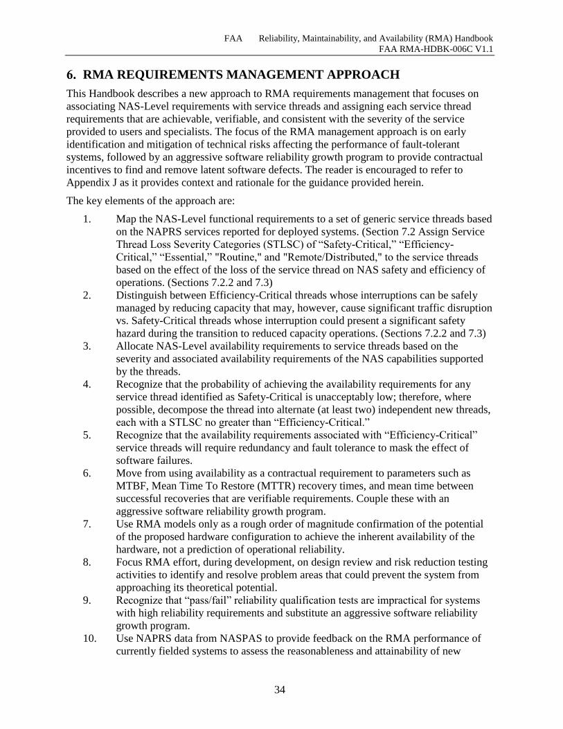
FAA Reliability, Maintainability, and Availability (RMA) Handbook
FAA RMA-HDBK-006C V1.1
34
RMA REQUIREMENTS MANAGEMENT APPROACH
This Handbook describes a new approach to RMA requirements management that focuses on
associating NAS-Level requirements with service threads and assigning each service thread
requirements that are achievable, verifiable, and consistent with the severity of the service
provided to users and specialists. The focus of the RMA management approach is on early
identification and mitigation of technical risks affecting the performance of fault-tolerant
systems, followed by an aggressive software reliability growth program to provide contractual
incentives to find and remove latent software defects. The reader is encouraged to refer to
Appendix J as it provides context and rationale for the guidance provided herein.
The key elements of the approach are:
1. Map the NAS-Level functional requirements to a set of generic service threads based
on the NAPRS services reported for deployed systems. (Section 7.2 Assign Service
Thread Loss Severity Categories (STLSC) of “Safety-Critical,” “Efficiency-
Critical,” “Essential,” "Routine," and "Remote/Distributed," to the service threads
based on the effect of the loss of the service thread on NAS safety and efficiency of
operations. (Sections 7.2.2 and 7.3)
2. Distinguish between Efficiency-Critical threads whose interruptions can be safely
managed by reducing capacity that may, however, cause significant traffic disruption
vs. Safety-Critical threads whose interruption could present a significant safety
hazard during the transition to reduced capacity operations. (Sections 7.2.2 and 7.3)
3. Allocate NAS-Level availability requirements to service threads based on the
severity and associated availability requirements of the NAS capabilities supported
by the threads.
4. Recognize that the probability of achieving the availability requirements for any
service thread identified as Safety-Critical is unacceptably low; therefore, where
possible, decompose the thread into alternate (at least two) independent new threads,
each with a STLSC no greater than “Efficiency-Critical.”
5. Recognize that the availability requirements associated with “Efficiency-Critical”
service threads will require redundancy and fault tolerance to mask the effect of
software failures.
6. Move from using availability as a contractual requirement to parameters such as
MTBF, Mean Time To Restore (MTTR) recovery times, and mean time between
successful recoveries that are verifiable requirements. Couple these with an
aggressive software reliability growth program.
7. Use RMA models only as a rough order of magnitude confirmation of the potential
of the proposed hardware configuration to achieve the inherent availability of the
hardware, not a prediction of operational reliability.
8. Focus RMA effort, during development, on design review and risk reduction testing
activities to identify and resolve problem areas that could prevent the system from
approaching its theoretical potential.
9. Recognize that “pass/fail” reliability qualification tests are impractical for systems
with high reliability requirements and substitute an aggressive software reliability
growth program.
10. Use NAPRS data from NASPAS to provide feedback on the RMA performance of
currently fielded systems to assess the reasonableness and attainability of new
FAA Reliability, Maintainability, and Availability (RMA) Handbook
FAA RMA-HDBK-006C V1.1
35
requirements, and to verify that the requirements for new systems will result in
systems with RMA characteristics that are at least as good as those of the systems
they replace.
11. Apply these principles throughout the acquisition process.
The application of these RMA management methods for the new approach is discussed in detail
in Section 8. These methods apply equally to new acquisitions and established iterative
development programs. All phases of the acquisition process are addressed, including
preliminary requirements analysis, allocation, preparation of procurement documents, proposal
evaluation, contractor monitoring, and design qualification and acceptance testing.
Throughout all phases of design and allocation, appropriately chosen SME should be utilized to
ensure successful incorporation of an operational viewpoint into the requirements. SMEs can be
both operational Air Traffic Control personnel from appropriate facility types and locations as
well as technical operations and maintenance personnel with insight into maintainability and
repair aspects of systems to be fielded. Early involvement of SMEs during procurement will
help to ensure both clarification of the expected role and utility of a future system, and help set
operational expectations for future systems. SME input should be carefully documented and
weighed against NAS EA functional expectations for a system and where necessary, fed back
into CONOPS.
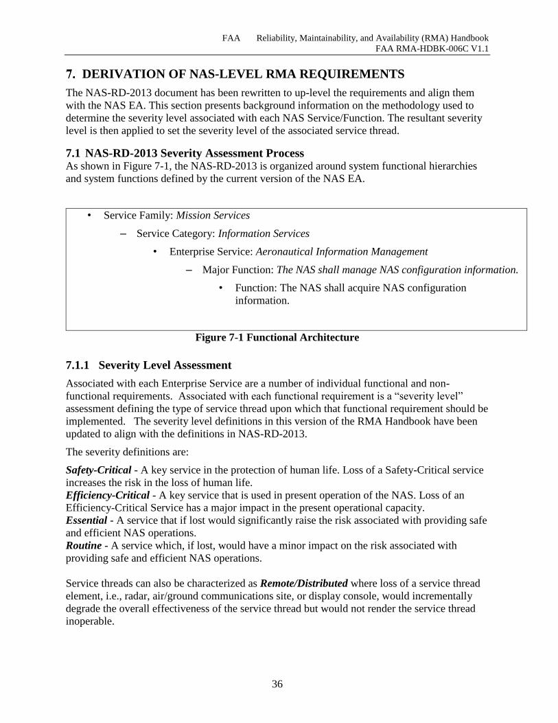
FAA Reliability, Maintainability, and Availability (RMA) Handbook
FAA RMA-HDBK-006C V1.1
36
DERIVATION OF NAS-LEVEL RMA REQUIREMENTS
The NAS-RD-2013 document has been rewritten to up-level the requirements and align them
with the NAS EA. This section presents background information on the methodology used to
determine the severity level associated with each NAS Service/Function. The resultant severity
level is then applied to set the severity level of the associated service thread.
7.1 NAS-RD-2013 Severity Assessment Process As shown in Figure 7-1, the NAS-RD-2013 is organized around system functional hierarchies
and system functions defined by the current version of the NAS EA.
• Service Family: Mission Services
– Service Category: Information Services
• Enterprise Service: Aeronautical Information Management
– Major Function: The NAS shall manage NAS configuration information.
• Function: The NAS shall acquire NAS configuration
information.
Figure 7-1 Functional Architecture
7.1.1 Severity Level Assessment
Associated with each Enterprise Service are a number of individual functional and non-
functional requirements. Associated with each functional requirement is a “severity level”
assessment defining the type of service thread upon which that functional requirement should be
implemented. The severity level definitions in this version of the RMA Handbook have been
updated to align with the definitions in NAS-RD-2013.
The severity definitions are:
Safety-Critical - A key service in the protection of human life. Loss of a Safety-Critical service
increases the risk in the loss of human life.
Efficiency-Critical - A key service that is used in present operation of the NAS. Loss of an
Efficiency-Critical Service has a major impact in the present operational capacity.
Essential - A service that if lost would significantly raise the risk associated with providing safe
and efficient NAS operations.
Routine - A service which, if lost, would have a minor impact on the risk associated with
providing safe and efficient NAS operations.
Service threads can also be characterized as Remote/Distributed where loss of a service thread
element, i.e., radar, air/ground communications site, or display console, would incrementally
degrade the overall effectiveness of the service thread but would not render the service thread
inoperable.
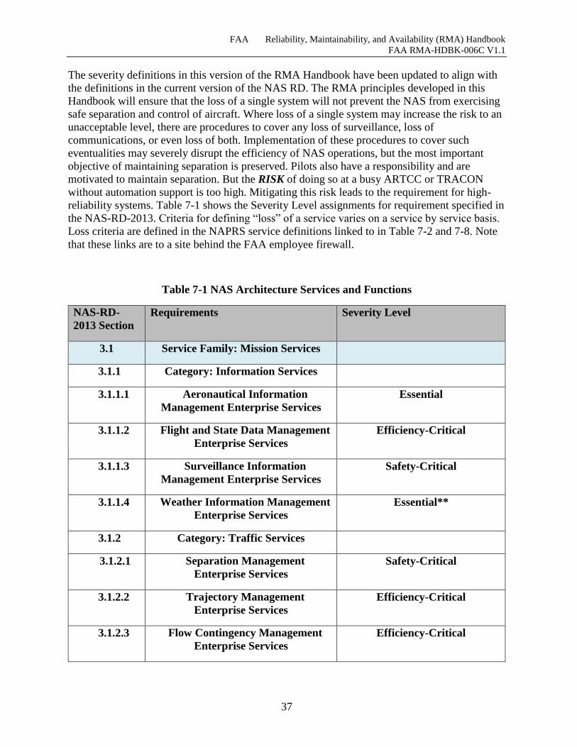
FAA Reliability, Maintainability, and Availability (RMA) Handbook
FAA RMA-HDBK-006C V1.1
37
The severity definitions in this version of the RMA Handbook have been updated to align with
the definitions in the current version of the NAS RD. The RMA principles developed in this
Handbook will ensure that the loss of a single system will not prevent the NAS from exercising
safe separation and control of aircraft. Where loss of a single system may increase the risk to an
unacceptable level, there are procedures to cover any loss of surveillance, loss of
communications, or even loss of both. Implementation of these procedures to cover such
eventualities may severely disrupt the efficiency of NAS operations, but the most important
objective of maintaining separation is preserved. Pilots also have a responsibility and are
motivated to maintain separation. But the RISK of doing so at a busy ARTCC or TRACON
without automation support is too high. Mitigating this risk leads to the requirement for high-
reliability systems. Table 7-1 shows the Severity Level assignments for requirement specified in
the NAS-RD-2013. Criteria for defining “loss” of a service varies on a service by service basis.
Loss criteria are defined in the NAPRS service definitions linked to in Table 7-2 and 7-8. Note
that these links are to a site behind the FAA employee firewall.
Table 7-1 NAS Architecture Services and Functions
NAS-RD-
2013 Section
Requirements Severity Level
3.1 Service Family: Mission Services
3.1.1 Category: Information Services
3.1.1.1 Aeronautical Information
Management Enterprise Services
Essential
3.1.1.2 Flight and State Data Management
Enterprise Services
Efficiency-Critical
3.1.1.3 Surveillance Information
Management Enterprise Services
Safety-Critical
3.1.1.4 Weather Information Management
Enterprise Services
Essential**
3.1.2 Category: Traffic Services
3.1.2.1 Separation Management
Enterprise Services
Safety-Critical
3.1.2.2 Trajectory Management
Enterprise Services
Efficiency-Critical
3.1.2.3 Flow Contingency Management
Enterprise Services
Efficiency-Critical
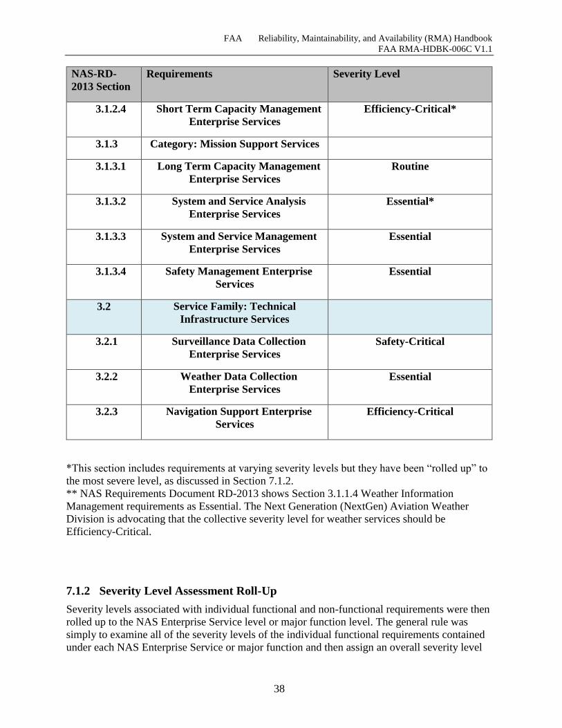
FAA Reliability, Maintainability, and Availability (RMA) Handbook
FAA RMA-HDBK-006C V1.1
38
NAS-RD-
2013 Section
Requirements Severity Level
3.1.2.4 Short Term Capacity Management
Enterprise Services
Efficiency-Critical*
3.1.3 Category: Mission Support Services
3.1.3.1 Long Term Capacity Management
Enterprise Services
Routine
3.1.3.2 System and Service Analysis
Enterprise Services
Essential*
3.1.3.3 System and Service Management
Enterprise Services
Essential
3.1.3.4 Safety Management Enterprise
Services
Essential
3.2 Service Family: Technical
Infrastructure Services
3.2.1 Surveillance Data Collection
Enterprise Services
Safety-Critical
3.2.2 Weather Data Collection
Enterprise Services
Essential
3.2.3 Navigation Support Enterprise
Services
Efficiency-Critical
*This section includes requirements at varying severity levels but they have been “rolled up” to
the most severe level, as discussed in Section 7.1.2.
** NAS Requirements Document RD-2013 shows Section 3.1.1.4 Weather Information
Management requirements as Essential. The Next Generation (NextGen) Aviation Weather
Division is advocating that the collective severity level for weather services should be
Efficiency-Critical.
7.1.2 Severity Level Assessment Roll-Up
Severity levels associated with individual functional and non-functional requirements were then
rolled up to the NAS Enterprise Service level or major function level. The general rule was
simply to examine all of the severity levels of the individual functional requirements contained
under each NAS Enterprise Service or major function and then assign an overall severity level
FAA Reliability, Maintainability, and Availability (RMA) Handbook
FAA RMA-HDBK-006C V1.1
39
based on the highest severity level of any of the individual constituent functional requirements
under it. However, mechanistically following this process could have led to unintended
consequences. In general, all or most of the functional requirements assigned to a NAS
Enterprise Service level have the same severity level, so it simply inherited the severity of its
constituent requirements. Where this was not the case, the severity level was rolled-up to the
major functional level.
While performing the roll-up, the severity level assignment of each individual functional
requirement was re-examined to make sure it was consistent within the context of the major
function under consideration. The guiding principle was that the severity level assigned to an
individual requirement must be realistic and constitute a significant factor in providing the
major function. The results of applying the severity level roll-up rule appear in the severity NAS
RD Roll-Up column in the matrices in Figure 7-9, Figure 7-10 and Figure 7-11 at the end of this
section.
NAS-RD-2013 maps enterprise requirements to NAS subsystems that contribute to those
requirements. The subsystems that were selected to be represented in the NAS-RD-2013 are
those that are under NAS configuration control. These subsystems are represented in the NAS-
SV-1H, the Facility, Service, and Equipment Profile (FSEP), or the NAS-MD-001. All selected
subsystems must be denoted as subsystems on the NAS-SV-1H. Variants, functions, and
components are not included. The roll-up process presupposes that all of the functional
requirements comprising a NAS service will eventually be allocated to the same system. In this
case, any lower severity functional requirements contained within a major function of a higher
severity simply inherit the higher severity of the major function and the system to which the
requirements of that major function are allocated.
Consider the case where a NAS service/major function includes requirements that are almost
certain to be allocated to different systems, for example, surveillance functions and weather
functions. Should availability requirements for a system be driven by the consequence of one of
its functional requirements being included in a critical major function? This is at the heart of the
conundrum of attempting to drive the RMA requirements for real systems from unallocated
functional requirements. The challenge is to devise a method for mapping the unallocated
requirements associated with the NAS EA to something more tangible that can be related to
specifications for real systems.
The method proposed is to relate the NAS-RD-2013 requirements to a set of real-world services
that are based on the services monitored by the National Airspace Performance Reporting
System (NAPRS), as defined in FAA Order JO 6040.15[30]. To distinguish these NAPRS-
based services from the NAS Architecture Services, they are designated as service threads, as
discussed in the next section.
7.2 Development of Service Threads NAS-RD-2013 services are supported by one or more service threads providing services to
user/specialists (i.e., pilots and controllers). One example is surveillance data derived from
sources and sensors, processed into tracks, to which relevant data is associated and displayed to
controllers. Another service thread is navigation data delivered to pilots. Service threads are
realized from interconnected facilities and systems.
FAA Reliability, Maintainability, and Availability (RMA) Handbook
FAA RMA-HDBK-006C V1.1
40
The FAA’s Air Traffic and Technical Operations organizations have for years monitored a set
of “service threads” under the NAPRS. NAPRS tracks the operational availability of what it
calls, “services” (not to be confused with the NAS EA Services). NAPRS tracks the operational
availability and other RMA characteristics of services delivered by individual service threads to
specialists. Since these services represent a “contract” between the Technical Operations and
Air Traffic Operations, NAPRS services do not include NAS services, such as navigation, that
are not used by air traffic controllers. (The performance of navigation facilities is monitored, but
no corresponding service is defined.)
RMA Service Thread development is based on NAPRS services defined in FAA Order 6040.15.
Basing the service threads on the NAPRS services provides several benefits. FAA personnel are
familiar with the NAPRS services and they provide a common basis of understanding among
the Air Traffic Operations, Technical Operations and headquarters personnel. The operational
data collected by NAPRS allows proposed RMA requirements to be compared with the
performance of currently fielded systems to provide a check on the reasonableness of the
requirements. The use of service threads permits the NAS architecture to evolve as components
within a thread are replaced without the need to change the thread itself. To realize these
benefits, the service threads used in this document should correlate as closely as possible with
the services defined in NAPRS services.
However, it has been necessary to define some additional service threads that are not presently
included in FAA Order JO 6040.15.
The NAPRS monitors the performance of operational systems, while the NAS-RD-2013 looks
toward requirements for future systems. Accordingly, new service threads will need to be
created from time to time as the NAS evolves. This process should be closely coordinated with
future revisions to NAPRS services.
The following section provides the traceability between the NAPRS services and the current list
of service threads used in this Handbook.
7.2.1 System of Systems Taxonomy of FAA Systems
FAA systems used to provide the capabilities, as described by the set of requirements specified
in the NAS-RD-2013, can be divided into four major categories: 1) Information Systems, 2)
Remote/Distributed and Standalone Systems, 3) Mission Support Systems and 4) Infrastructure
and Enterprise Systems. Figure 7-2 NAS System Taxonomy presents the NAS System
Taxonomy on which definitions and requirements allocation methodologies for the various
categories of systems can be based. Strategies for each of these system categories are presented
in the paragraphs that follow.
What is represented in Figure 7-2 is a system of systems taxonomy. As such, most NAS
services and resulting service threads will be comprised of systems from more than one of the
major categories in the taxonomy. As a result, some NAS services are provided by systems of
multiple types.
For example, En Route Automation Modernization (ERAM), which is an Automation System
under the Information Systems category in the taxonomy, also relies on and employs other
Information Systems such as the En Route Communications Gateway (ECG). In addition, it
receives inputs from multiple instances of Remote / Distributed & Standalone Systems such as
FAA Reliability, Maintainability, and Availability (RMA) Handbook
FAA RMA-HDBK-006C V1.1
41
Air Route Surveillance Radars (ARSR) and is supported locally by Infrastructure Systems such
as power and HVAC. NAS wide Enterprise System services are provided by Communication
Transport Systems e.g., the NAS Messaging Replacement (NMR) via the FAA
Telecommunications Infrastructure (FTI).
For the purposes of this Handbook, these taxonomy categories are provided as guidance in
categorizing a system or service such that the RMA approaches described in this Handbook are
properly applied. In cases where it is not clear which category a system or service falls under or
which RMA approach should be applied, then a subject matter expert (SME) should be
consulted for further clarification.
1. Information Systems are the primary focus of the requirements allocation methodology
described in this Handbook. These systems are generally computer systems located in
major facilities staffed by ATC personnel. They consolidate large quantities of
information for use by operational personnel in performing the NAS Air Traffic Control
Mission. They usually have high severity and availability requirements, because their
failure could affect large volumes of information and many users. Typically, they
employ fault tolerance, redundancy, and automatic fault detection and recovery to
achieve high availability. These systems can be mapped to the NAS Services and
Capabilities functional requirements.
2. The Remote/Distributed and Standalone Systems category includes remote sensors,
remote air-to-ground communications, inter-facility data communications and
navigation sites, as well as distributed subsystems such as display terminals that may be
located within a major facility. Failures of single elements, or even combinations of
elements, can degrade performance at an operational facility, but generally they do not
result in the total loss of the surveillance, communications, navigation, or display
capability. Most of the service threads in the Remote/Distributed and Standalone
Systems category are covered by the diversity techniques required by FAA Order
6000.36, Communications Diversity.
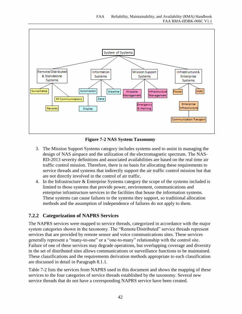
FAA Reliability, Maintainability, and Availability (RMA) Handbook
FAA RMA-HDBK-006C V1.1
42
Figure 7-2 NAS System Taxonomy
3. The Mission Support Systems category includes systems used to assist in managing the
design of NAS airspace and the utilization of the electromagnetic spectrum. The NAS-
RD-2013 severity definitions and associated availabilities are based on the real time air
traffic control mission. Therefore, there is no basis for allocating these requirements to
service threads and systems that indirectly support the air traffic control mission but that
are not directly involved in the control of air traffic.
4. In the Infrastructure & Enterprise Systems category the scope of the systems included is
limited to those systems that provide power, environment, communications and
enterprise infrastructure services to the facilities that house the information systems.
These systems can cause failures to the systems they support, so traditional allocation
methods and the assumption of independence of failures do not apply to them.
7.2.2 Categorization of NAPRS Services
The NAPRS services were mapped to service threads, categorized in accordance with the major
system categories shown in the taxonomy. The “Remote/Distributed” service threads represent
services that are provided by remote sensor and voice communications sites. These services
generally represent a “many-to-one” or a “one-to-many” relationship with the control site.
Failure of one of these services may degrade operations, but overlapping coverage and diversity
in the set of distributed sites allows communications or surveillance functions to be maintained.
These classifications and the requirements derivation methods appropriate to each classification
are discussed in detail in Paragraph 8.1.1.
Table 7-2 lists the services from NAPRS used in this document and shows the mapping of these
services to the four categories of service threads established by the taxonomy. Several new
service threads that do not have a corresponding NAPRS service have been created.
FAA Reliability, Maintainability, and Availability (RMA) Handbook
FAA RMA-HDBK-006C V1.1
43
R/F Navigation Service – Navigation Support includes functions performed by ground-
based navigation and landing systems that provide electronic reference signals to assist
an aircraft in determining its position relative to a navigation fix or runway. It also
includes the provision of visual reference to flight crews.
RALS - R/F Approach and Landing Service – TBD
VGS - Visual Guidance Service – TBD
TVSB Terminal Voice Switch Backup - Provides backup air-to-ground and ground-to-
ground voice communications essential for the terminal domain of aircraft flights to
provide safe, orderly and efficient flow of air traffic
Power is addressed in Section 7.7.3.1, where a methodology to derive RMA requirements for
power distribution services are presented.
The first column of Table 7-2 provides the names of each of the services defined in NAPRS. A
“(NEW)” entry in this column indicates a newly created service thread that does not have a
corresponding facility or service in NAPRS. The remaining columns indicate the category of the
service thread (Information, Remote/Distributed, Support, or Infrastructure) and the domain of
the service thread (Terminal, En Route, or Other). NAPRS services that have not been mapped
to a service thread are also identified in these columns.
The revised RMA requirements development process has augmented the NAPRS services in
Table 7-2 with some additional service threads to include those services that are part of NAS
but not included in the list of NAPRS services. NAPRS services representing lower level
services from remote inputs that are included in composite higher level services provided to
user/specialists, have been mapped to the Remote/Distributed column in Table 7-2 because the
overall availability of the distributed communications and surveillance architecture is addressed
by a “bottom-up” application of diversity and overlapping coverage techniques as directed by
FAA Order 6000.36 instead of a top-down mathematical allocation of NAS-RD-2013
availability requirements. This is a consequence of the complex set of criteria that can affect the
number and placement of remote sensor and communication sites and the overall availability of
communications and surveillance services within a facility’s airspace. Many of these factors
such as the effects of geography, terrain, traffic patterns, and man-made obstacles are not easily
quantified and must be separately considered on a case-by-case basis. It is not practical to
attempt to establish a priority set of requirements for services in the Remote/Distributed and
Standalone Systems category.
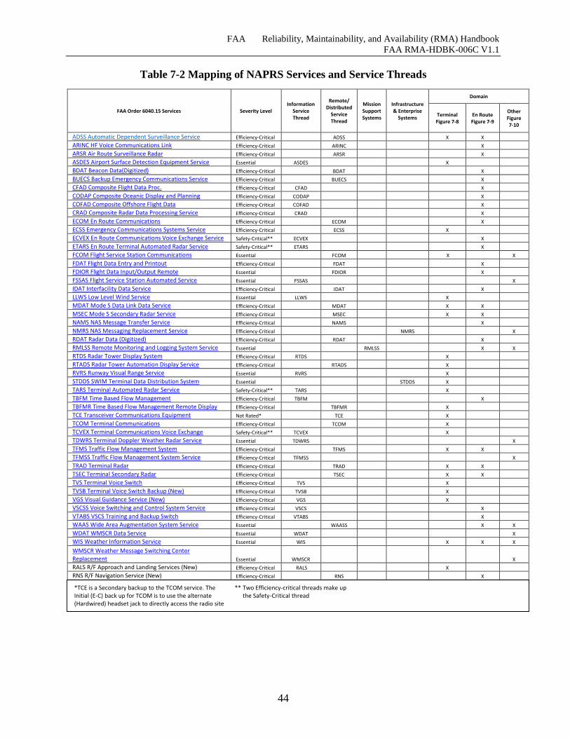
FAA Reliability, Maintainability, and Availability (RMA) Handbook
FAA RMA-HDBK-006C V1.1
44
Table 7-2 Mapping of NAPRS Services and Service Threads
FAA Order 6040.15 Services Severity Level Information
Service Thread
Remote/ Distributed
Service Thread
Mission Support Systems
Infrastructure & Enterprise
Systems
Domain
Terminal Figure 7-8
En Route Figure 7-9
Other Figure 7-10
ADSS Automatic Dependent Surveillance Service Efficiency-Critical ADSS X X
ARINC HF Voice Communications Link Efficiency-Critical ARINC X
ARSR Air Route Surveillance Radar Efficiency-Critical ARSR X
ASDES Airport Surface Detection Equipment Service Essential ASDES X
BDAT Beacon Data(Digitized) Efficiency-Critical BDAT X
BUECS Backup Emergency Communications Service Efficiency-Critical BUECS X
CFAD Composite Flight Data Proc. Efficiency-Critical CFAD X
CODAP Composite Oceanic Display and Planning Efficiency-Critical CODAP X
COFAD Composite Offshore Flight Data Efficiency-Critical COFAD X
CRAD Composite Radar Data Processing Service Efficiency-Critical CRAD X
ECOM En Route Communications Efficiency-Critical ECOM X
ECSS Emergency Communications Systems Service Efficiency-Critical ECSS X
ECVEX En Route Communications Voice Exchange Service Safety-Critical** ECVEX X
ETARS En Route Terminal Automated Radar Service Safety-Critical** ETARS X
FCOM Flight Service Station Communications Essential FCOM X X
FDAT Flight Data Entry and Printout Efficiency-Critical FDAT X
FDIOR Flight Data Input/Output Remote Essential FDIOR X
FSSAS Flight Service Station Automated Service Essential FSSAS X
IDAT Interfacility Data Service Efficiency-Critical IDAT X
LLWS Low Level Wind Service Essential LLWS X
MDAT Mode S Data Link Data Service Efficiency-Critical MDAT X X
MSEC Mode S Secondary Radar Service Efficiency-Critical MSEC X X
NAMS NAS Message Transfer Service Efficiency-Critical NAMS X
NMRS NAS Messaging Replacement Service Efficiency-Critical NMRS X
RDAT Radar Data (Digitized) Efficiency-Critical RDAT X
RMLSS Remote Monitoring and Logging System Service Essential RMLSS X X
RTDS Radar Tower Display System Efficiency-Critical RTDS X
RTADS Radar Tower Automation Display Service Efficiency-Critical RTADS X
RVRS Runway Visual Range Service Essential RVRS X
STDDS SWIM Terminal Data Distribution System Essential STDDS X
TARS Terminal Automated Radar Service Safety-Critical** TARS X
TBFM Time Based Flow Management Efficiency-Critical TBFM X
TBFMR Time Based Flow Management Remote Display Efficiency-Critical TBFMR X
TCE Transceiver Communications Equipment Not Rated* TCE X
TCOM Terminal Communications Efficiency-Critical TCOM X
TCVEX Terminal Communications Voice Exchange Safety-Critical** TCVEX X
TDWRS Terminal Doppler Weather Radar Service Essential TDWRS X
TFMS Traffic Flow Management System Efficiency-Critical TFMS X X
TFMSS Traffic Flow Management System Service Efficiency-Critical TFMSS X
TRAD Terminal Radar Efficiency-Critical TRAD X X
TSEC Terminal Secondary Radar Efficiency-Critical TSEC X X
TVS Terminal Voice Switch Efficiency-Critical TVS X
TVSB Terminal Voice Switch Backup (New) Efficiency-Critical TVSB X
VGS Visual Guidance Service (New) Efficiency-Critical VGS X
VSCSS Voice Switching and Control System Service Efficiency-Critical VSCS X
VTABS VSCS Training and Backup Switch Efficiency-Critical VTABS X
WAAS Wide Area Augmentation System Service Essential WAASS X X
WDAT WMSCR Data Service Essential WDAT X
WIS Weather Information Service Essential WIS X X X
WMSCR Weather Message Switching Center Replacement Essential WMSCR X
RALS R/F Approach and Landing Services (New) Efficiency-Critical RALS X
RNS R/F Navigation Service (New) Efficiency-Critical RNS X
*TCE is a Secondary backup to the TCOM service. The ** Two Efficiency-critical threads make up Initial (E-C) back up for TCOM is to use the alternate the Safety-Critical thread (Hardwired) headset jack to directly access the radio site
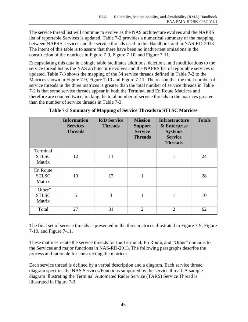
FAA Reliability, Maintainability, and Availability (RMA) Handbook
FAA RMA-HDBK-006C V1.1
45
The service thread list will continue to evolve as the NAS architecture evolves and the NAPRS
list of reportable Services is updated. Table 7-2 provides a numerical summary of the mapping
between NAPRS services and the service threads used in this Handbook and in NAS-RD-2013.
The intent of this table is to assure that there have been no inadvertent omissions in the
construction of the matrices in Figure 7-9, Figure 7-10, and Figure 7-11.
Encapsulating this data in a single table facilitates additions, deletions, and modifications to the
service thread list as the NAS architecture evolves and the NAPRS list of reportable services is
updated. Table 7-3 shows the mapping of the 54 service threads defined in Table 7-2 to the
Matrices shown in Figure 7-9, Figure 7-10 and Figure 7-11. The reason that the total number of
service threads in the three matrices is greater than the total number of service threads in Table
7-2 is that some service threads appear in both the Terminal and En Route Matrices and
therefore are counted twice, making the total number of service threads in the matrices greater
than the number of service threads in Table 7-3.
Table 7-3 Summary of Mapping of Service Threads to STLSC Matrices
Information
Services
Threads
R/D Service
Threads
Mission
Support
Service
Threads
Infrastructure
& Enterprise
Systems
Service
Threads
Totals
Terminal
STLSC
Matrix
12 11 1 24
En Route
STLSC
Matrix
10 17 1 28
“Other”
STLSC
Matrix
5 3 1 1 10
Total 27 31 2 2 62
The final set of service threads is presented in the three matrices illustrated in Figure 7-9, Figure
7-10, and Figure 7-11.
These matrices relate the service threads for the Terminal, En Route, and “Other” domains to
the Services and major functions in NAS-RD-2013. The following paragraphs describe the
process and rationale for constructing the matrices.
Each service thread is defined by a verbal description and a diagram. Each service thread
diagram specifies the NAS Services/Functions supported by the service thread. A sample
diagram illustrating the Terminal Automated Radar Service (TARS) Service Thread is
illustrated in Figure 7-3.
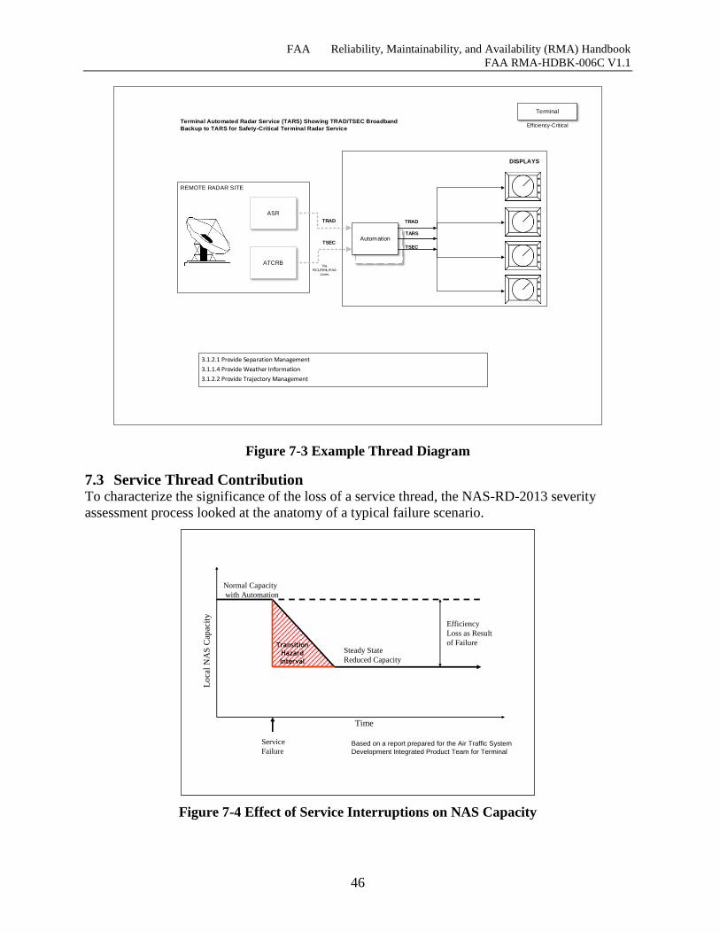
FAA Reliability, Maintainability, and Availability (RMA) Handbook
FAA RMA-HDBK-006C V1.1
46
ARTS
ARTS
ARTS
ART
S
ART
S
ARTS
ARTS
REMOTE RADAR SITE
ASR
3.1.2.1 Provide Separation Management
3.1.1.4 Provide Weather Information
3.1.2.2 Provide Trajectory Management
Terminal Automated Radar Service (TARS) Showing TRAD/TSEC Broadband
Backup to TARS for Safety-Critical Terminal Radar Service
ATCRB
Automation
DISPLAYS
TSEC
TRAD
Via
RCL/RML/FAA
Lines
*
*
*
*
*
*
*
*
*
*
*
*
TRAD
TARS
TSEC
Terminal
Efficiency-Critical
Figure 7-3 Example Thread Diagram
7.3 Service Thread Contribution To characterize the significance of the loss of a service thread, the NAS-RD-2013 severity
assessment process looked at the anatomy of a typical failure scenario.
Figure 7-4 Effect of Service Interruptions on NAS Capacity
Transition
Hazard
Interval
Time
Lo
cal
NA
S C
apac
ity
Normal Capacity
with Automation
Steady State
Reduced Capacity
Service
Failure
Efficiency
Loss as Result
of Failure
Based on a report prepared for the Air Traffic System
Development Integrated Product Team for Terminal
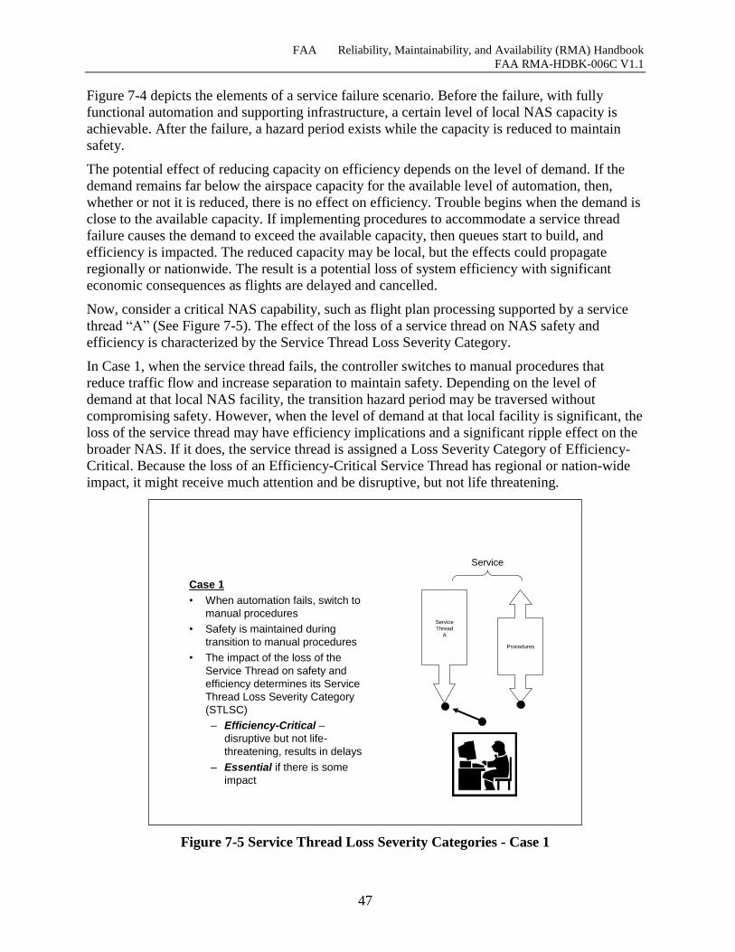
FAA Reliability, Maintainability, and Availability (RMA) Handbook
FAA RMA-HDBK-006C V1.1
47
Figure 7-4 depicts the elements of a service failure scenario. Before the failure, with fully
functional automation and supporting infrastructure, a certain level of local NAS capacity is
achievable. After the failure, a hazard period exists while the capacity is reduced to maintain
safety.
The potential effect of reducing capacity on efficiency depends on the level of demand. If the
demand remains far below the airspace capacity for the available level of automation, then,
whether or not it is reduced, there is no effect on efficiency. Trouble begins when the demand is
close to the available capacity. If implementing procedures to accommodate a service thread
failure causes the demand to exceed the available capacity, then queues start to build, and
efficiency is impacted. The reduced capacity may be local, but the effects could propagate
regionally or nationwide. The result is a potential loss of system efficiency with significant
economic consequences as flights are delayed and cancelled.
Now, consider a critical NAS capability, such as flight plan processing supported by a service
thread “A” (See Figure 7-5). The effect of the loss of a service thread on NAS safety and
efficiency is characterized by the Service Thread Loss Severity Category.
In Case 1, when the service thread fails, the controller switches to manual procedures that
reduce traffic flow and increase separation to maintain safety. Depending on the level of
demand at that local NAS facility, the transition hazard period may be traversed without
compromising safety. However, when the level of demand at that local facility is significant, the
loss of the service thread may have efficiency implications and a significant ripple effect on the
broader NAS. If it does, the service thread is assigned a Loss Severity Category of Efficiency-
Critical. Because the loss of an Efficiency-Critical Service Thread has regional or nation-wide
impact, it might receive much attention and be disruptive, but not life threatening.
Figure 7-5 Service Thread Loss Severity Categories - Case 1
Case 1
• When automation fails, switch to
manual procedures
• Safety is maintained during
transition to manual procedures
• The impact of the loss of the
Service Thread on safety and
efficiency determines its Service
Thread Loss Severity Category
(STLSC)
– Efficiency-Critical –
disruptive but not life-
threatening, results in delays
– Essential if there is some
impact
Service
Thread
A
Procedures
Service
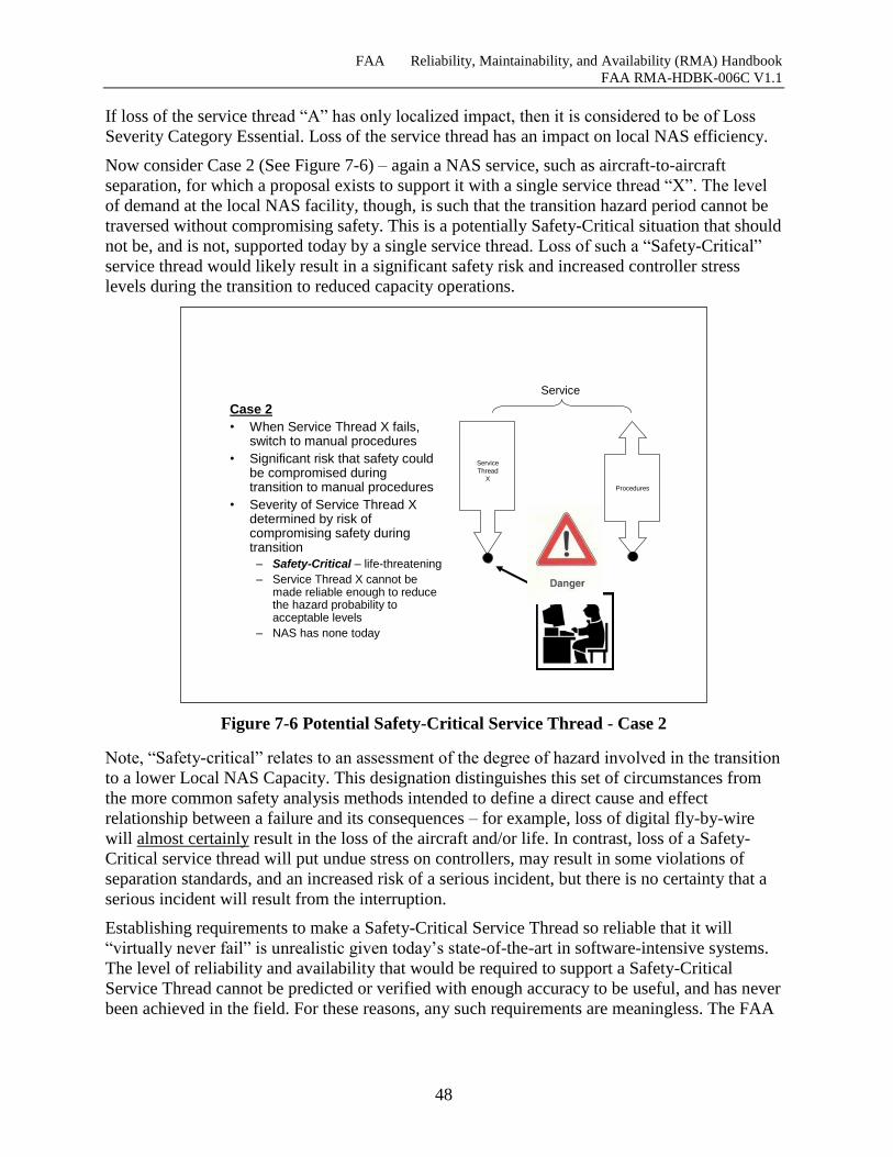
FAA Reliability, Maintainability, and Availability (RMA) Handbook
FAA RMA-HDBK-006C V1.1
48
If loss of the service thread “A” has only localized impact, then it is considered to be of Loss
Severity Category Essential. Loss of the service thread has an impact on local NAS efficiency.
Now consider Case 2 (See Figure 7-6) – again a NAS service, such as aircraft-to-aircraft
separation, for which a proposal exists to support it with a single service thread “X”. The level
of demand at the local NAS facility, though, is such that the transition hazard period cannot be
traversed without compromising safety. This is a potentially Safety-Critical situation that should
not be, and is not, supported today by a single service thread. Loss of such a “Safety-Critical”
service thread would likely result in a significant safety risk and increased controller stress
levels during the transition to reduced capacity operations.
Figure 7-6 Potential Safety-Critical Service Thread - Case 2
Note, “Safety-critical” relates to an assessment of the degree of hazard involved in the transition
to a lower Local NAS Capacity. This designation distinguishes this set of circumstances from
the more common safety analysis methods intended to define a direct cause and effect
relationship between a failure and its consequences – for example, loss of digital fly-by-wire
will almost certainly result in the loss of the aircraft and/or life. In contrast, loss of a Safety-
Critical service thread will put undue stress on controllers, may result in some violations of
separation standards, and an increased risk of a serious incident, but there is no certainty that a
serious incident will result from the interruption.
Establishing requirements to make a Safety-Critical Service Thread so reliable that it will
“virtually never fail” is unrealistic given today’s state-of-the-art in software-intensive systems.
The level of reliability and availability that would be required to support a Safety-Critical
Service Thread cannot be predicted or verified with enough accuracy to be useful, and has never
been achieved in the field. For these reasons, any such requirements are meaningless. The FAA
Case 2
• When Service Thread X fails, switch to manual procedures
• Significant risk that safety could be compromised during transition to manual procedures
• Severity of Service Thread X determined by risk of compromising safety during transition
– Safety-Critical – life-threatening
– Service Thread X cannot be made reliable enough to reduce the hazard probability to acceptable levels
– NAS has none today
Service
Thread
X
Procedures
Service
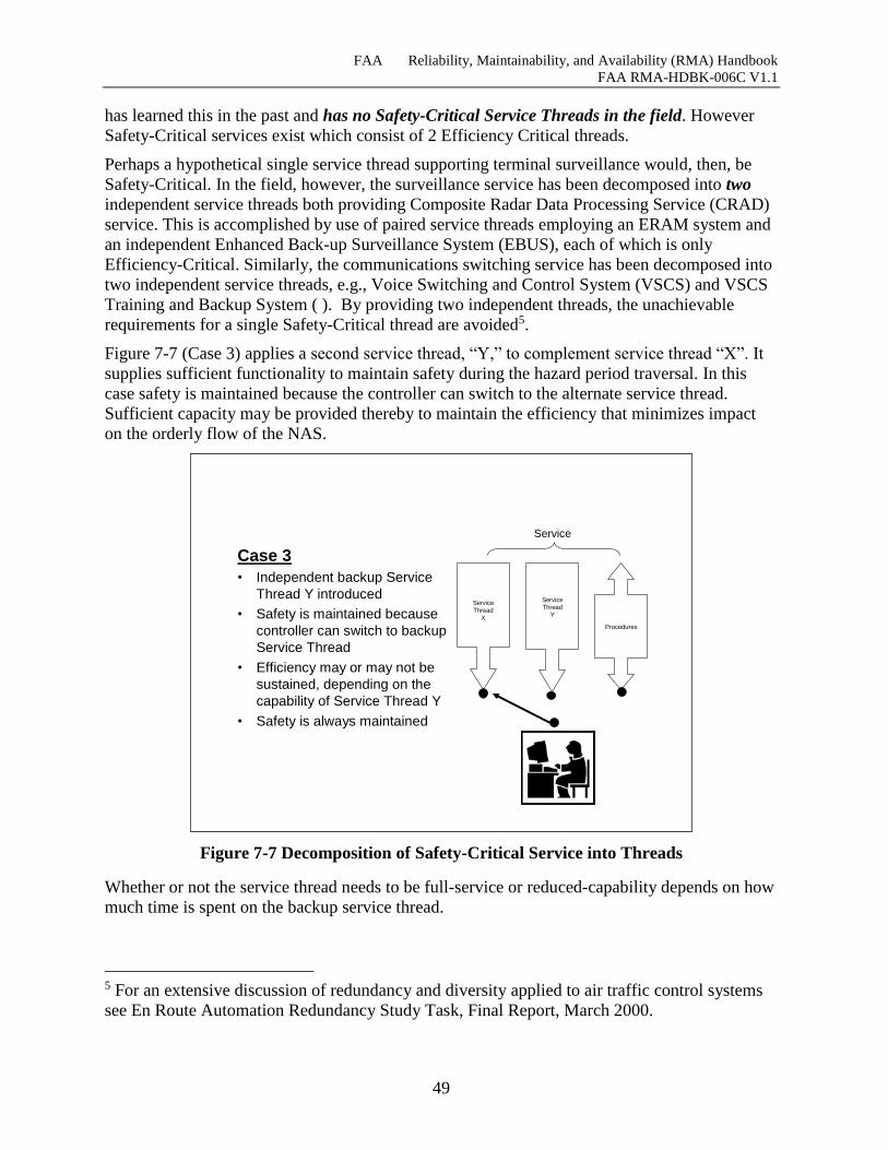
FAA Reliability, Maintainability, and Availability (RMA) Handbook
FAA RMA-HDBK-006C V1.1
49
has learned this in the past and has no Safety-Critical Service Threads in the field. However
Safety-Critical services exist which consist of 2 Efficiency Critical threads.
Perhaps a hypothetical single service thread supporting terminal surveillance would, then, be
Safety-Critical. In the field, however, the surveillance service has been decomposed into two
independent service threads both providing Composite Radar Data Processing Service (CRAD)
service. This is accomplished by use of paired service threads employing an ERAM system and
an independent Enhanced Back-up Surveillance System (EBUS), each of which is only
Efficiency-Critical. Similarly, the communications switching service has been decomposed into
two independent service threads, e.g., Voice Switching and Control System (VSCS) and VSCS
Training and Backup System ( ). By providing two independent threads, the unachievable
requirements for a single Safety-Critical thread are avoided5.
Figure 7-7 (Case 3) applies a second service thread, “Y,” to complement service thread “X”. It
supplies sufficient functionality to maintain safety during the hazard period traversal. In this
case safety is maintained because the controller can switch to the alternate service thread.
Sufficient capacity may be provided thereby to maintain the efficiency that minimizes impact
on the orderly flow of the NAS.
Figure 7-7 Decomposition of Safety-Critical Service into Threads
Whether or not the service thread needs to be full-service or reduced-capability depends on how
much time is spent on the backup service thread.
5 For an extensive discussion of redundancy and diversity applied to air traffic control systems
see En Route Automation Redundancy Study Task, Final Report, March 2000.
Case 3
• Independent backup Service
Thread Y introduced
• Safety is maintained because
controller can switch to backup
Service Thread
• Efficiency may or may not be
sustained, depending on the
capability of Service Thread Y
• Safety is always maintained
Service
Thread
X
Procedures
ServiceThread
Y
Service
FAA Reliability, Maintainability, and Availability (RMA) Handbook
FAA RMA-HDBK-006C V1.1
50
The bottom line is – if a new service thread is determined to be “Safety-Critical,” i.e. the
transition to manual procedures presents a significant risk to safety, the potential new service
thread must be divided into at least two independent service threads that can serve as primary
and backup(s).
7.4 Scaling of Service Threads The severity of a service thread cannot always be assessed without examining the context in
which the service is deployed. In particular the distinction between Efficiency–Critical and
Essential Service Threads and between Essential and Routine may depend on the size and type
of the staffed facility, and on environmental factors including geography, air space design, and
local climate conditions.
This Section introduces the concept of Scaling of Service Threads based on Facility Groups and
the environment. This revision of the Handbook has updated the STLSC matrix format to
account for service thread scalability by severity in a manner similar to the mapping of Facility
Power System Architecture to Service Threads in previous revisions.
7.4.1 Facility Grouping Schema
The schema in this section places the various types of FAA facilities into eight groups (Table
7-4) to provide an additional level of accuracy when obtaining Service Thread Loss Severity
Categories (STLSCs). In some instances, the severities of the same service thread may vary
based on the type of facility utilizing it, so it is important to add this additional dimension to the
STLSC assessment.
There are four major groups that facilities will fall under: ARTCCs, TRACONs, ATCTs and
Unstaffed Facilities. Staffed Facilities that are combinations of any of the three major groups
should be classified under the portion of the facility that has more airspace and volume of traffic
under its control, see descriptions in Table 7-4.
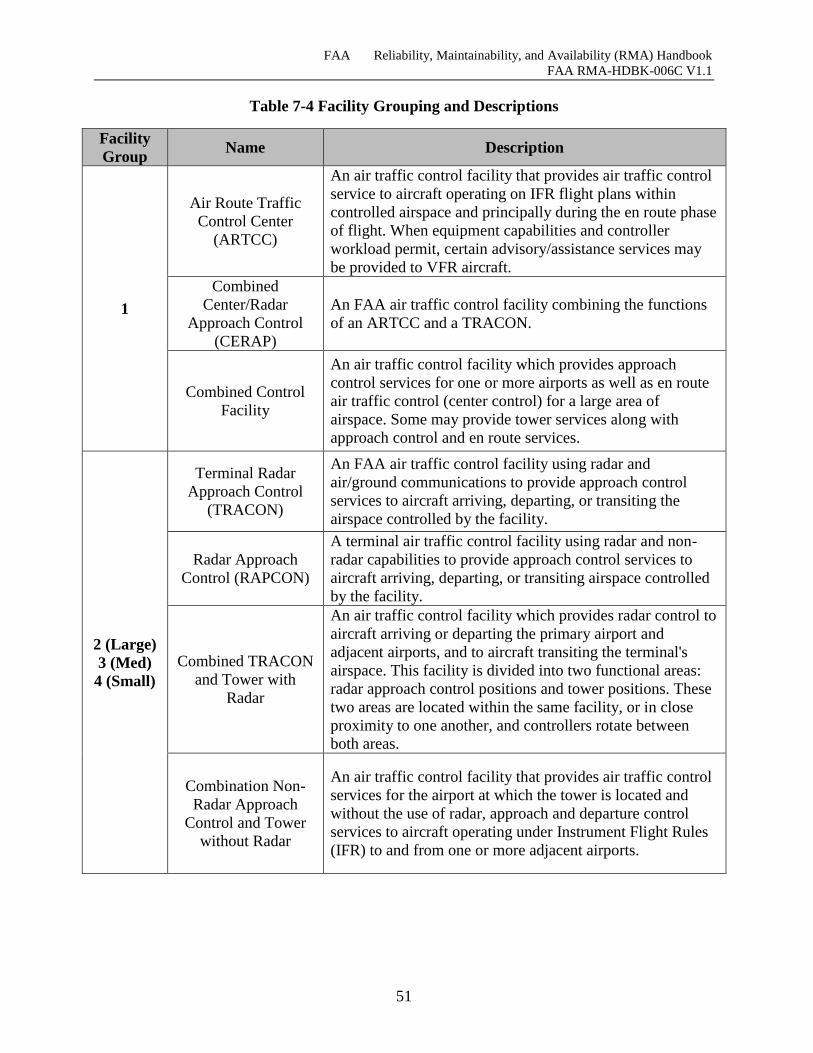
FAA Reliability, Maintainability, and Availability (RMA) Handbook
FAA RMA-HDBK-006C V1.1
51
Table 7-4 Facility Grouping and Descriptions
Facility
Group Name Description
1
Air Route Traffic
Control Center
(ARTCC)
An air traffic control facility that provides air traffic control
service to aircraft operating on IFR flight plans within
controlled airspace and principally during the en route phase
of flight. When equipment capabilities and controller
workload permit, certain advisory/assistance services may
be provided to VFR aircraft.
Combined
Center/Radar
Approach Control
(CERAP)
An FAA air traffic control facility combining the functions
of an ARTCC and a TRACON.
Combined Control
Facility
An air traffic control facility which provides approach
control services for one or more airports as well as en route
air traffic control (center control) for a large area of
airspace. Some may provide tower services along with
approach control and en route services.
2 (Large)
3 (Med)
4 (Small)
Terminal Radar
Approach Control
(TRACON)
An FAA air traffic control facility using radar and
air/ground communications to provide approach control
services to aircraft arriving, departing, or transiting the
airspace controlled by the facility.
Radar Approach
Control (RAPCON)
A terminal air traffic control facility using radar and non-
radar capabilities to provide approach control services to
aircraft arriving, departing, or transiting airspace controlled
by the facility.
Combined TRACON
and Tower with
Radar
An air traffic control facility which provides radar control to
aircraft arriving or departing the primary airport and
adjacent airports, and to aircraft transiting the terminal's
airspace. This facility is divided into two functional areas:
radar approach control positions and tower positions. These
two areas are located within the same facility, or in close
proximity to one another, and controllers rotate between
both areas.
Combination Non-
Radar Approach
Control and Tower
without Radar
An air traffic control facility that provides air traffic control
services for the airport at which the tower is located and
without the use of radar, approach and departure control
services to aircraft operating under Instrument Flight Rules
(IFR) to and from one or more adjacent airports.
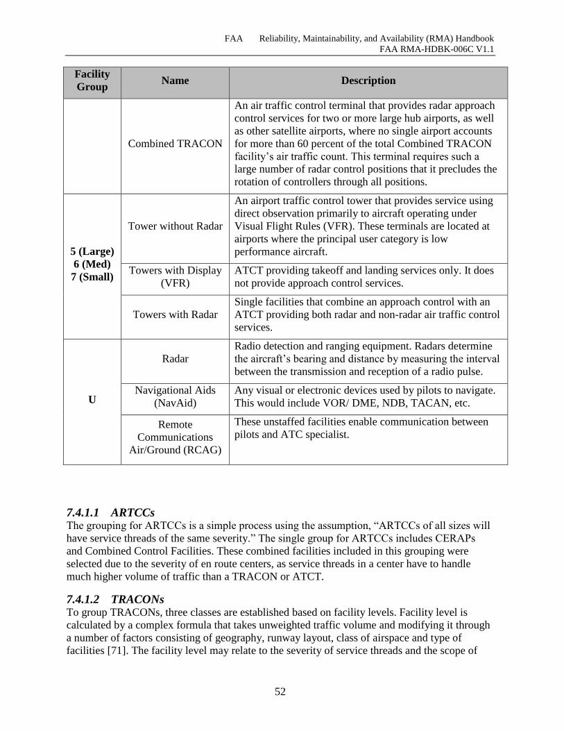
FAA Reliability, Maintainability, and Availability (RMA) Handbook
FAA RMA-HDBK-006C V1.1
52
Facility
Group Name Description
Combined TRACON
An air traffic control terminal that provides radar approach
control services for two or more large hub airports, as well
as other satellite airports, where no single airport accounts
for more than 60 percent of the total Combined TRACON
facility’s air traffic count. This terminal requires such a
large number of radar control positions that it precludes the
rotation of controllers through all positions.
5 (Large)
6 (Med)
7 (Small)
Tower without Radar
An airport traffic control tower that provides service using
direct observation primarily to aircraft operating under
Visual Flight Rules (VFR). These terminals are located at
airports where the principal user category is low
performance aircraft.
Towers with Display
(VFR)
ATCT providing takeoff and landing services only. It does
not provide approach control services.
Towers with Radar
Single facilities that combine an approach control with an
ATCT providing both radar and non-radar air traffic control
services.
U
Radar
Radio detection and ranging equipment. Radars determine
the aircraft’s bearing and distance by measuring the interval
between the transmission and reception of a radio pulse.
Navigational Aids
(NavAid)
Any visual or electronic devices used by pilots to navigate.
This would include VOR/ DME, NDB, TACAN, etc.
Remote
Communications
Air/Ground (RCAG)
These unstaffed facilities enable communication between
pilots and ATC specialist.
7.4.1.1 ARTCCs The grouping for ARTCCs is a simple process using the assumption, “ARTCCs of all sizes will
have service threads of the same severity.” The single group for ARTCCs includes CERAPs
and Combined Control Facilities. These combined facilities included in this grouping were
selected due to the severity of en route centers, as service threads in a center have to handle
much higher volume of traffic than a TRACON or ATCT.
7.4.1.2 TRACONs To group TRACONs, three classes are established based on facility levels. Facility level is
calculated by a complex formula that takes unweighted traffic volume and modifying it through
a number of factors consisting of geography, runway layout, class of airspace and type of
facilities [71]. The facility level may relate to the severity of service threads and the scope of

FAA Reliability, Maintainability, and Availability (RMA) Handbook
FAA RMA-HDBK-006C V1.1
53
impact during service downtimes. The three TRACON groups as they relate to facility level are
captured in Table 7-5 and can be referenced in Table 7-4, Facility Group 2, 3 and 4.
Table 7-5 TRACON Grouping
TRACONs Small Medium Large
Facility Level 𝑋 ≤ 8 9≤ 𝑋 ≤ 10 𝑋 ≥11
The Large class of TRACONs consists of all the major facilities that deal with significantly
more traffic than the rest of the facilities in the country. Following that reasoning, the remaining
TRACONs are placed into either the Small or Medium class based on their facility level which
is also directly related to the volume of traffic. As an example,
Figure 7-8 shows the difference in traffic volume between the various levels of facilities. It is
clear that Facility Level 11 and 12 are in a category of their own with some facilities handling
up to about 2 million operations per year. There is also the consideration for facilities that might
change groupings due to an upgrade or downgrade, but fortunately the criteria for changing
facility levels sets a proper standard to avoid constant upgrade or downgrade in facility levels
[72]. This lack of change in facility levels can also be seen in Figure 7-8, following the data
shown from 2006 to 2012 [74], the facilities bordering the grouping constraints have not
changed levels at all despite the overall decrease in air traffic.
Figure 7-8 Comparison of TRACONs over time by annual total number of operations
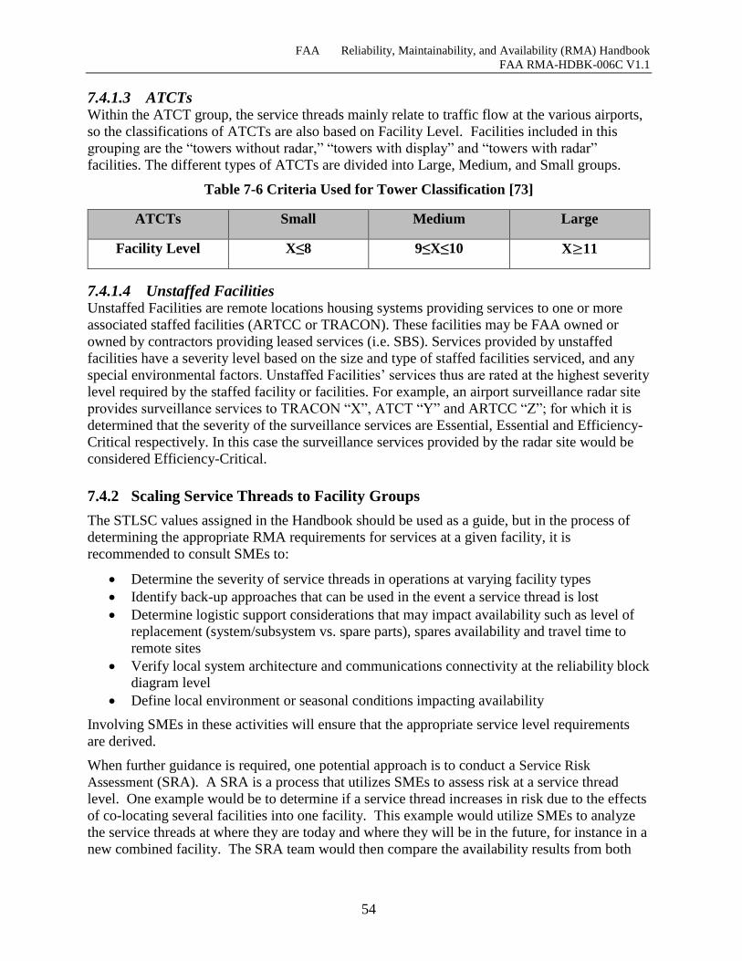
FAA Reliability, Maintainability, and Availability (RMA) Handbook
FAA RMA-HDBK-006C V1.1
54
7.4.1.3 ATCTs Within the ATCT group, the service threads mainly relate to traffic flow at the various airports,
so the classifications of ATCTs are also based on Facility Level. Facilities included in this
grouping are the “towers without radar,” “towers with display” and “towers with radar”
facilities. The different types of ATCTs are divided into Large, Medium, and Small groups.
Table 7-6 Criteria Used for Tower Classification [73]
ATCTs Small Medium Large
Facility Level X≤8 9≤X≤10 X≥11
7.4.1.4 Unstaffed Facilities Unstaffed Facilities are remote locations housing systems providing services to one or more
associated staffed facilities (ARTCC or TRACON). These facilities may be FAA owned or
owned by contractors providing leased services (i.e. SBS). Services provided by unstaffed
facilities have a severity level based on the size and type of staffed facilities serviced, and any
special environmental factors. Unstaffed Facilities’ services thus are rated at the highest severity
level required by the staffed facility or facilities. For example, an airport surveillance radar site
provides surveillance services to TRACON “X”, ATCT “Y” and ARTCC “Z”; for which it is
determined that the severity of the surveillance services are Essential, Essential and Efficiency-
Critical respectively. In this case the surveillance services provided by the radar site would be
considered Efficiency-Critical.
7.4.2 Scaling Service Threads to Facility Groups
The STLSC values assigned in the Handbook should be used as a guide, but in the process of
determining the appropriate RMA requirements for services at a given facility, it is
recommended to consult SMEs to:
Determine the severity of service threads in operations at varying facility types
Identify back-up approaches that can be used in the event a service thread is lost
Determine logistic support considerations that may impact availability such as level of
replacement (system/subsystem vs. spare parts), spares availability and travel time to
remote sites
Verify local system architecture and communications connectivity at the reliability block
diagram level
Define local environment or seasonal conditions impacting availability
Involving SMEs in these activities will ensure that the appropriate service level requirements
are derived.
When further guidance is required, one potential approach is to conduct a Service Risk
Assessment (SRA). A SRA is a process that utilizes SMEs to assess risk at a service thread
level. One example would be to determine if a service thread increases in risk due to the effects
of co-locating several facilities into one facility. This example would utilize SMEs to analyze
the service threads at where they are today and where they will be in the future, for instance in a
new combined facility. The SRA team would then compare the availability results from both
FAA Reliability, Maintainability, and Availability (RMA) Handbook
FAA RMA-HDBK-006C V1.1
55
the existing and future assessments and determine if there are any decreases in availability. One
potential area where availability could decrease is from changes in the back-up procedures or
services. If this occurs then the SRA team would identify mitigations that when implemented
could return the service threads to the levels where they are today. This is only one example of
many areas, including EIS, where the SRA process could be applied to ensure service thread
availability in the NAS.
7.4.3 Environmental Complications
Some services may require higher STLSC values at certain facilities due to environmental
factors. For example, at a tower where there are often visibility issues, such as fog, or terrain
blocking line-of-sight, surface surveillance may warrant a greater STLSC value than at a facility
where there is usually optimal out-the-window visibility. In these cases, the Handbook assigned
STLSC values should be used as a recommendation, but SMEs should also be consulted to
make the most optimal determination for NAS safety and efficiency.
7.5 Assign Service Thread Loss Severity Category In assessing the severity of a service thread failure, there are two issues to consider:
1. How hazardous is the transition to a reduced steady state capacity, e.g., is safety
compromised while controllers increase separation and reduce traffic flow to achieve the
reduced capacity state?
2. What is the severity of the impact of the service thread failure on NAS efficiency and
traffic flow? This severity depends on several non-system related factors such as the
level of demand, level of the facility, time of day, and weather conditions.
If the transition risk is acceptable, the only issue in question is the effect of a failure on the
efficiency of NAS operations. If the effect could cause widespread delays and flight
cancellations, the service thread is considered “Efficiency-Critical.” If the reduction in NAS
capacity results in some, but not widespread, disruptions to traffic flow, then the service thread
is rated “Essential.” If, however, the hazard during transition to reduced traffic flow is
significant, prudent steps must be taken to reduce the probability of that hazardous transition to
an acceptable level. Experience has shown that this cannot be accomplished with a single
service thread – instead a prudent design dictates use of two, independent service threads each
designed to support the Safety-Critical requirement together with a simple manual capability for
switching from one to the other (sometimes called a “knife switch” capability)6 .
6 The most significant weakness of the HOST-DARC system was the reduced functionality available with the
backup data path (DARC). Analysis of the NASPAS data shows that 98% of the time controllers were required to
use the DARC system is to accommodate scheduled outages. This is essentially a procedural issue concerning
Technical Operations technicians, although the close coupling of redundant Host processors is a significant factor.
Whether or not the percentage of time spent on DARC to accommodate scheduled Host outages could have been
reduced, scheduled outages would have always comprise a significant portion of total Host outages due to the
desirability of retaining closely coupled resources within a data path to provide high availability, as discussed
above. Therefore, to mitigate the effects of scheduled and unscheduled outages on full service availability, a higher
functionality secondary data path was implemented through EBUS (EBUS does not fully implement flight data
processing). The HOST replacement system, ERAM, has implemented secondary pathing that provides reduced
capacity and different functionality but the same service.
FAA Reliability, Maintainability, and Availability (RMA) Handbook
FAA RMA-HDBK-006C V1.1
56
Redundancy alone is not enough to mitigate the effects of system faults. Redundant system
components can provide continuing operations after a system fault only if the resource
experiencing said fault is independent of its equivalent, redundant component. In the case of
standby redundancy, the ability to provide continuing operations depends on the successful
operation of complex automatic fault detection and recovery mechanisms. The beneficial effects
of redundancy are therefore maximized when resources are organized into active redundant
groups, and each group is made to be independent of the other groups. In this context,
independence means that resources in one group do not rely on resources either contained in
other groups or relied upon by the resources comprising other groups. Independence applies to
hardware and software.
FAA systems operate at extremely high availability in large part because of the physical
independence between the primary and secondary data path equipment. This is in contrast to the
tight coupling of resources generally found between redundant resources within a data path.
This tight coupling induces a risk, however, that certain failure modes will result in the loss of
all tightly coupled resources within a data path. One or more separate active data paths loosely
coupled to the failed data path is provided to ensure there is no disruption of service when these
more comprehensive failure modes are encountered. Simple switching mechanism (or isolated
voting mechanism) is also needed between the multiple data paths, which in the current system
consists of a capability to switch nearly instantaneously between service threads by depressing a
single button. Therefore, we conclude that to continue to provide the high availability of service
redundant independent data paths are needed for the target architecture.
For these reasons, the target architecture for systems supporting critical services should provide
separate and independent full functionality continuously active data paths, with each data path
being composed of tightly coupled redundant components. This will be required to ensure for
the future the extremely high availability of equipment and services that has been achieved with
the current system, and to mitigate the effects of scheduled outages better than is the case with
the current system. The use of independent data paths is critical to achieving extremely high
availability, and care must be taken not to compromise this characteristic during any phase of
the system life cycle. Full functionality on both data paths is needed to mitigate the impacts of
planned and unplanned primary channel outages, both of which are inevitable in an automation
system.
This leads us to the following definitions for Service Thread Loss Severity Categories with
comments on the defining characteristics of each:
1) Safety-Critical – Service thread loss would present an unacceptable safety hazard during
transition to reduced capacity operations.
Loss of a service thread supporting the service would impact safety unless a simple,
manual switchover to a backup service thread was successfully accomplished.
Depending on operational requirements, the secondary service thread might have a
lower capacity or functionality than the primary.
FAA experience has shown that this capability is achievable if the service is
delivered by at least two independent service threads, each built with off-the-shelf
components in fault tolerant configurations.
FAA Reliability, Maintainability, and Availability (RMA) Handbook
FAA RMA-HDBK-006C V1.1
57
2) Efficiency-Critical – Service thread loss could be accommodated by reducing capacity
without compromising safety, but the resulting impact might have a localized or system-
wide economic impact on NAS efficiency.
Experience has shown that this is achievable by a service thread built of off-the-shelf
components in a fault tolerant configuration.
3) Essential – Service thread loss could be accommodated by reducing capacity without
compromising safety, with only a localized impact on NAS efficiency.
Experience has shown that this is achievable by a service thread built of good
quality, industrial-grade, off-the-shelf components.
4) Routine – A service which, if lost, would have a minor impact on the risk associated
with providing safe and efficient NAS operations.
For Remote/Distributed threads, loss of a service thread element, i.e., radar, air/ground
communications site, or display console, would incrementally degrade the overall effectiveness
of the service thread but would not render the service thread inoperable.
The NAS-RD-2013 RMA requirements development process has assigned a STLSC to each
identified service thread.
7.6 STLSC Matrix Development The results of this process are summarized in the matrices in Figure 7-9, Figure 7-10, and
Figure 7-11 that are provided as samples from NAS-RD-20137 . These matrices provide the
mapping between the NAS architecture capabilities in Table 7-1 and the service threads in
Table 7-2.
The three matrices represent the service threads contained in each of the Terminal, En Route,
and “Other” domains. All of the matrices contain service threads in both the Information and
Remote/Distributed and Standalone Systems categories illustrated in Table 7-1. In addition, the
“Other” matrix contains the service threads in the Support Systems and Infrastructure and
Enterprise Information Systems categories of the taxonomy. Although the matrices are
organized around the domains of the service threads, the development of the RMA requirements
for the service threads depends on their category in the taxonomy (Information,
Remote/Distributed and Standalone, Support, or Infrastructure and Enterprise Information
Systems).
The column to the right of the NAS Services/Functions in the matrices represents the results of
“rolling up” the severities assigned to each of the individual NAS-RD-2013 functional
requirements contained in a NAS architecture capability to a single value representing the
severity of the entire NAS function. Each NAS architecture capability is assigned a severity
level of “Critical,” “Essential,” or “Routine.” (The only capabilities having a “Routine” severity
were those capabilities associated with non-real-time mission support. All of the capabilities
associated with the real-time air traffic control mission have a severity of “Essential” or higher.)
Each matrix is divided into two sections. The top section above the black row contains
information concerning the characteristics of the service threads, including the overall STLSC
7 In the event of a discrepancy between these matrices and those in NAS-RD-20XX, the NAS EA-RD-20XX takes
precedence.
FAA Reliability, Maintainability, and Availability (RMA) Handbook
FAA RMA-HDBK-006C V1.1
58
for each service thread and differentiates the service levels required for differing facility sizes.
The section of the matrix below the black row shows the mapping between the NAS
Service/Functions and the service threads.
The individual cell entries in a row indicate which of the service threads support a given major
function. The individual cell entries in a service thread column indicate which of the various
architecture capabilities are supported by the service thread. The numerical entries in the cells
represent the STLSC associated with the loss of a service thread on each of the specific
architecture capabilities that are associated with that thread. A cell entry of “N” for “not rated”
indicates one of two conditions: (1) Loss of the major function is overshadowed by the loss of a
much more critical major function, which renders the provision of the major function
meaningless in that instance, or (2) The major function is used very infrequently, and should not
be treated as a driver for RMA requirements. For example loss of the ability to communicate
with aircraft may affect the capability to provide NAS status advisories, but the effect of the
loss of air-ground communications on the far more critical capability to maintain aircraft-to-
aircraft separation overshadows the capability to provide NAS status advisories so it is “Not
Rated” in this instance.
A column labeled “Manual Procedures” has been added on the right side of each of the
matrices, with a “P” in every cell. This is to illustrate that the NAS capabilities are provided by
FAA operational personnel using a combination of automation tools (service threads) and
manual procedures. When service threads fail, manual procedures can still be employed to
continue to provide the NAS capabilities supported by the failed service thread(s). The “P” in
every cell indicates that there are always manual procedures to provide the NAS capabilities, so
that the NAS-RD-2013 availability requirements associated with Service/Function severity can
be achieved despite service thread interruptions.
The first row below the service thread names shows the pairing of service threads providing
Safety-Critical services. The Safety-Critical service thread pairs are coded red and designated
by an arrow spanning the two service threads. Note that the STLSC for each of the service
threads making up a Safety-Critical pair is “Efficiency-Critical.” This recognizes the fact that a
single service thread is incapable of achieving the level of availability needed for Safety-Critical
applications. The availability associated with each STLSC was obtained by “rolling up” the
availabilities associated with NAS Service/Functions as discussed in Section 7.1.2.
The overall Service Thread Loss Severity Category (STLSC) for each service thread was
obtained by “rolling up” the STLSCs for each of the cells in a service thread column. The
overall STLSC for each service thread is represented by the highest severity of any of the cells
in the service thread’s column. The overall STLSCs are in the second row below the service
thread names.
The row(s) beneath these two rows represent the power system architectures associated with the
service threads. Power distribution systems used by the service threads are discussed in greater
detail in Section 7.7.3.
Each of the matrices contains two categories of service threads: service threads representing
information services provided to controllers by systems located within the facility, and service
threads representing Remote/Distributed Services that include remote surveillance and
communications sites serving the facility and intercommunications between the facility and
other remote facilities.
FAA Reliability, Maintainability, and Availability (RMA) Handbook
FAA RMA-HDBK-006C V1.1
59
The Remote/Distributed Service Threads provide a STLSC for reference, but use a “D” in the
cells of the R/D Service Thread columns in addition to a STLSC value to indicate which NAS
capabilities are supported by the R/D Service Thread and their severity. The “D” is used to
indicate that the diversity techniques in FAA Order 6000.36 are used to achieve the required
level of availability. It should be noted that an R/D Service Thread is a generic representation of
a service thread with multiple instantiations. For example, in an ARTCC, the En Route
Communications Service Thread (ECOM) will typically have several dozen instantiations of the
service thread at specific locations (e.g. Atlantic City RCAG) to provide complete and
overlapping coverage for the center’s airspace.
The columns of the matrices have been color-coded to indicate which of the service threads are
not directly mapped from the NAPRS services. Grey indicates newly created service threads
that are not included in NAPRS.
7.6.1 Terminal STLSC Matrix
The matrix in Figure 7-9 shows all service threads associated with the Terminal domain. These
include Information Service Threads, Remote/Distributed Service Threads and Infrastructure
and Enterprise Systems Service Threads.
NOTE(s):
TARS is a “Safety-Critical” Umbrella Service comprised of two Efficiency-Critical
Service Threads (see Figure E-27). Figure E-27illustrates two redundant Terminal
Service Threads i.e., TARS-1 and TARS-2.
Terminal Communications Voice Exchange (TCVEX) is a “Safety-Critical”
Umbrella Service comprised of two Efficiency-Critical Service Threads i.e.,
Terminal Voice Communications Safety-Critical Service Thread Pair (see Figure
E-45). Figure E-45 illustrates a Service Thread Pair consisting of two redundant
Efficiency-Critical Terminal Service Threads.
The Remote/Distributed Service Threads are characterized by equipment that is located at the
control facility, (e.g. TRACON) and equipment that is remotely located and linked to the
control facility by one or more communications paths. The equipment in the control facility is
powered by the Critical bus of the Critical Power Distribution System. The remote equipment is
powered by a separate power source. The last row above the black row, “Remote Site Power
Architecture,” specifies the power architecture requirements at the remote sites. In contrast with
the Information Service Threads, Remote/Distributed Threads do not associate a quantitative
STLSC availability requirement with each service thread.
The overall availability of the critical surveillance and communications services provided by
these R/D Service Threads is achieved by employing diversity and redundancy techniques to
circumvent failures of individual service thread instantiations. The diversity requirements for
the service threads with a STLSC rating of “D” are contained in FAA Order 6000.36A,
Communications and Surveillance Service Diversity. Although these threads support critical
NAS-RD-2013 capabilities, the required availability is achieved, not by a single service thread
instantiation, but by a diverse architecture of distributed surveillance and communications sites
with overlapping coverage.
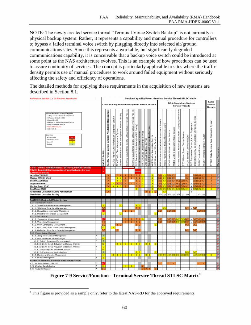
FAA Reliability, Maintainability, and Availability (RMA) Handbook
FAA RMA-HDBK-006C V1.1
60
NOTE: The newly created service thread “Terminal Voice Switch Backup” is not currently a
physical backup system. Rather, it represents a capability and manual procedure for controllers
to bypass a failed terminal voice switch by plugging directly into selected air/ground
communications sites. Since this represents a workable, but significantly degraded
communications capability, it is conceivable that a backup voice switch could be introduced at
some point as the NAS architecture evolves. This is an example of how procedures can be used
to assure continuity of services. The concept is particularly applicable to sites where the traffic
density permits use of manual procedures to work around failed equipment without seriously
affecting the safety and efficiency of operations.
The detailed methods for applying these requirements in the acquisition of new systems are
described in Section 8.1.
Figure 7-9 Service/Function - Terminal Service Thread STLSC Matrix8
8 This figure is provided as a sample only, refer to the latest NAS-RD for the approved requirements.
Reference Section 7.6 of the RMA Handbook
I & ES
Service
Threads
NA
S R
D R
oll-U
p
Fa
cilit
y P
ow
er
Sy
ste
m In
he
ren
t A
va
ila
bilit
y R
eq
uir
em
en
t
AS
DE
S A
irp
ort
Su
rfa
ce
De
tectio
n E
qu
ipm
en
t S
erv
ice
TF
MS
Tra
ffic
Flo
w M
an
ag
em
en
t S
yste
m
TB
FM
R T
ime
Ba
se
d F
low
Ma
na
ge
me
nt R
em
ote
Dis
pla
y
Te
rmin
al S
urv
eill
an
ce
Sa
fety
-Critica
l S
erv
ice
Th
rea
d P
air (
1)
Te
rmin
al S
urv
eill
an
ce
Sa
fety
-Critica
l S
erv
ice
Th
rea
d P
air (
2)
TV
S T
erm
ina
l V
oic
e S
witch
(N
AP
RS
Fa
cili
ty)
TV
SB
Te
rmin
al V
oic
e S
witch
Ba
cku
p
RV
RS
Ru
nw
ay V
isu
al R
an
ge
Se
rvic
e
VG
S V
isu
al G
uid
an
ce
Se
rvic
e
RA
LS
R/F
Ap
pro
ach
an
d L
an
din
g S
erv
ice
s
WIS
We
ath
er
Info
rma
tio
n S
erv
ice
LL
WS
Lo
w L
eve
l W
ind
Se
rvic
e
AD
SS
Au
tom
atic D
ep
en
de
nt S
urv
eill
an
ce
Se
rvic
e
FC
OM
Flig
ht S
erv
ice
Sta
tio
n C
om
mu
nic
atio
ns
MD
AT
Mo
de
S D
ata
Lin
k D
ata
Se
rvic
e
MS
EC
Mo
de
S S
eco
nd
ary
Ra
da
r S
erv
ice
RT
AD
S R
em
ote
To
we
r A
lph
an
um
eric D
isp
lay S
yste
m S
erv
ice
RT
DS
Ra
da
r T
ow
er
Dis
pla
y S
yste
m
TC
OM
Te
rmin
al C
om
mu
nic
atio
ns
TC
E T
ran
sce
ive
r C
om
mu
nic
atio
ns E
qu
ipm
en
t
EC
SS
Em
erg
en
cy C
om
mu
nic
atio
ns S
yste
ms S
erv
ice
TR
AD
Te
rmin
al R
ad
ar
TS
EC
Te
rmin
al S
eco
nd
ary
Ra
da
r
ST
DD
S S
WIM
Te
rmin
al D
ata
Dis
trib
utio
n S
yste
m
Ma
nu
al P
roce
du
res
1
1
E-C 2 2 2 2 2 2 3 3 D(2) D(3) D(2) D(2) D(2) D(2) D(2) D(2) 2 P
E-C 3 3 2 2 2 2 3 3 D(2) D(3) D(2) D(2) D(2) D(2) D(2) D(2) 2 P
E-C 3 3 2 2 2 3 3 D(2) D(3) D(2) D(2) D(2) D(2) D(2) D(2) D(2) D(2) 2 P
E-C 3 2 2 2 2 2 2 3 3 D(2) D(3) D(2) D(2) D(2) D(2) D(2) N D(2) D(2) D(2) 2 P
E-C 3 3 3 2 2 2 3 3 D(2) D(3) D(2) D(2) D(2) D(2) D(2) N D(2) D(2) D(2) 2 P
E 3 3 D(3) D(3) D(3) D(3) D(3) D(3) D(3) N D(3) D(3) D(3) 3 P
E-C 2 2 3 2 D(3) N
2/3 2/3 2/3 2/3 2/3 2/3 2/3 2/3 2/3
3.1.1 Information Services
3.1.1.1 Aeronautical Information Management E 3 3 3 P
3.1.1.2 Flight and State Data Management E-C 2 2 D(3) D(2) N D(2) P
3.1.1.3 Surveillance InformationManagment S-C 2 2 D(2) D(2) D(2) D(2) D(2) P
3.1.1.4 Weather Information Management E 3 3 P
3.1.2 Traffic Services
3.1.2.1 Separation Management S-C 2 2 2 2 3 D(2) D(2) D(2) D(3) D(3) D(2) N D(2)D(2) D(2) P
3.1.2.2 Trajectory Management E-C 2 2 2 2 D(2) D(2) D(2) D(3) D(3) D(2) N D(2)D(2) D(2) P
3.1.2.3 Flow Contingency Management E-C 2 2 2 2 3 D(2) D(2) P
3.1.2.4 (.0-1 only) Short Term Capacity Management E 3 P
3.1.2.4 (all other) Short Term Capacity Management E-C 2 2 2 D(2) D(2) P
3.1.3 Mission Support Services
3.1.3.1 Long Term Capacity Management * R P
3.1.3.2.0-1 System and Service Analysis * E P
3.1.3.2.0-1.0-1 System and Service Analysis * R P
3.1.3.2.0-1 (.0-2 thru.0-4) System and Service Analysis E 3 3 3 3 3 3 3 3 3 P
3.1.3.2.0-1 (.0-5 thru.0-7) System and Service Analysis * E P
3.1.3.2.0-2 (all) System and Service Analysis * E P
3.1.3.2.0-3 System and Service Analysis R 3 3 3 D(3) D(3) P
3.1.3.3 System and Service Management E 3 3 3 3 3 3 3 3 3 D(3) D(3) D(3) D(3) D(3) D(3) D(3) D(3)D(3) D(3) 3 P
3.1.3.4 Safety Management * E P
3.2.1 Surveillance Data Collection * S-C 2 2 2 2 2 P
3.2.2 Weather Data Collection * E 3 3 2 P
3.2.3 Navigation Support * E-C 2 2 2 2 P
Small Tower STLSC
Associated Unstaffed Facility Architecture
Distributed Unstaffed Facility
NAS RD-2013 Section 3.1 Mission Services
Service/Capability/Power -Terminal Service Thread STLSC Matrix
Control Facility Information Systems Service ThreadsR/D & Standalone Systems
Service Threads
TARS Terminal Automated Radar Service (Umbrella Service)TCVEX Terminal Communications Voice Exchange Service
(Umbrella Service)
Large TRACON STLSC
Medium TRACON STLSC
Small TRACON STLSC
NAS RD-2013 Section 3.2 Technical Infrastructure Services
Large Tower STLSC
Medium Tower STLSC
Service Thread Loss Severity Categories:
1 Safety-Critical = Paired Eff. Crit. Thread
2 Efficiency-Critical = .9999
3 Essential = .999
2/3 Based on Highest Associated Facility
M Mission Support Services
P Manual Procedures
N (Not Rated)
Color Key:
Safety-Critical S-C
Efficiency-Critical E-C
Essential E
Routine R
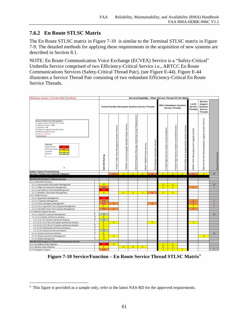
FAA Reliability, Maintainability, and Availability (RMA) Handbook
FAA RMA-HDBK-006C V1.1
61
7.6.2 En Route STLSC Matrix
The En Route STLSC matrix in Figure 7-10 is similar to the Terminal STLSC matrix in Figure
7-9. The detailed methods for applying these requirements in the acquisition of new systems are
described in Section 8.1.
NOTE: En Route Communication Voice Exchange (ECVEX) Service is a “Safety-Critical”
Umbrella Service comprised of two Efficiency-Critical Service i.e., ARTCC En Route
Communications Services (Safety-Critical Thread Pair), (see Figure E-44). Figure E-44
illustrates a Service Thread Pair consisting of two redundant Efficiency-Critical En Route
Service Threads.
Figure 7-10 Service/Function – En Route Service Thread STLSC Matrix9
9 This figure is provided as a sample only, refer to the latest NAS-RD for the approved requirements.
Reference Section 7.6 of the RMA Handbook
I & ES
Service
Threads
Mission
Support
Systems
Service
Threads
NA
S R
D R
oll-U
p
TF
MS
S T
raffic
Flo
w M
an
ag
em
nt S
yste
m S
erv
ice
TD
WR
S T
erm
ina
l D
op
ple
r W
ea
the
r R
ad
ar
Se
rvic
e
WM
SC
R W
ea
the
r M
essa
ge
Sw
itch
ing
Ce
nte
r R
ep
lace
me
nt
WD
AT
WM
SC
R D
ata
Se
rvic
e
WIS
We
ath
er
Info
rma
tio
n S
erv
ice
FC
OM
Flig
ht S
erv
ice
Sta
tio
n C
om
mu
nic
atio
ns
FS
SA
S F
ligh
t S
erv
ice
Sta
tio
n A
uto
ma
ted
Se
rvic
e
WA
AS
Wid
e A
rea
Au
gm
en
tatio
n S
yste
m S
erv
ice
NM
RS
N
AS
Me
ssa
gin
g a
nd
Lo
gg
ing
Syste
m
RM
LS
S R
em
ote
Mo
nitro
ing
an
d L
og
gin
g S
yste
m S
erv
ice
Ma
nu
al P
roce
du
res
2 3 3 3 2 3 3 3 2 3 M
3.1.1 Information Services
3.1.1.1 Aeronautical Information Management E 3 3 M
3.1.1.2 Flight and State Data Management E-C 3 3 2 P
3.1.1.3 Surveillance InformationManagment* S-C
3.1.1.4 Weather Information Management E 3 3 3 2 3 3
3.1.2 Traffic Services
3.1.2.1 Separation Management S-C
3.1.2.2 Trajectory Management E-C 2 P
3.1.2.3 Flow Contingency Management E-C 2 2 2 P
3.1.2.4 (.0-1 only) Short Term Capacity Management E 3 P
3.1.2.4 (all other) Short Term Capacity Management E-C 2 2
3.1.3 Mission Support Services
3.1.3.1 Long Term Capacity Management * R M
3.1.3.2.0-1 System and Service Analysis * E
3.1.3.2.0-1.0-1 System and Service Analysis * R
3.1.3.2.0-1 (.0-2 thru.0-4) System and Service Analysis E 3 3 3
3.1.3.2.0-1 (.0-5 thru.0-7) System and Service Analysis * E
3.1.3.2.0-2 (all) System and Service Analysis) * E
3.1.3.2.0-3 System and Service Analysis * R
3.1.3.2 System and Service Analysis * E M
3.1.3.3 System and Service Management E 3 3
3.1.3.4 Safety Management * E
3.2.1 Surveillance Data Collection S-C 3 3 3
3.2.2 Weather Data Collection E 3 3 3 3 3
3.2.3 Navigation Support E-C 3 3 3 P
Service/Capability - Other Service Thread STLSC Matrix
R/
Control Facility Information Systems Service ThreadsR/D & Standalone Systems
Service Threads
Safety Critical Thread PairingService Thread Loss Severity Category
NAS RD-2013 Section 3.1 Mission Services
NAS RD-2013 Section 3.2 Technical Infrastructure Services
Service Thread Loss Severity Categories:
1 Safety-Critical = Paired Eff. Crit. Thread
2 Efficiency-Critical = .9999
3 Essential = .999
2/3 Based on Highest Associated Facility
M Mission Support Services
P Manual Procedures
N (Not Rated)
Color Key:
Safety-Critical S-C
Efficiency-Critical E-C
Essential E
Routine R
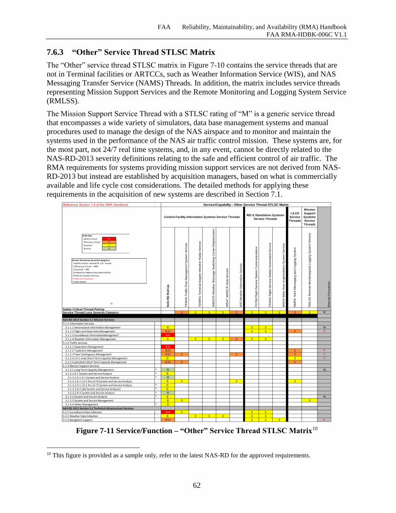
FAA Reliability, Maintainability, and Availability (RMA) Handbook
FAA RMA-HDBK-006C V1.1
62
7.6.3 “Other” Service Thread STLSC Matrix
The “Other” service thread STLSC matrix in Figure 7-10 contains the service threads that are
not in Terminal facilities or ARTCCs, such as Weather Information Service (WIS), and NAS
Messaging Transfer Service (NAMS) Threads. In addition, the matrix includes service threads
representing Mission Support Services and the Remote Monitoring and Logging System Service
(RMLSS).
The Mission Support Service Thread with a STLSC rating of “M” is a generic service thread
that encompasses a wide variety of simulators, data base management systems and manual
procedures used to manage the design of the NAS airspace and to monitor and maintain the
systems used in the performance of the NAS air traffic control mission. These systems are, for
the most part, not 24/7 real time systems, and, in any event, cannot be directly related to the
NAS-RD-2013 severity definitions relating to the safe and efficient control of air traffic. The
RMA requirements for systems providing mission support services are not derived from NAS-
RD-2013 but instead are established by acquisition managers, based on what is commercially
available and life cycle cost considerations. The detailed methods for applying these
requirements in the acquisition of new systems are described in Section 7.1.
Figure 7-11 Service/Function – “Other” Service Thread STLSC Matrix10
10 This figure is provided as a sample only, refer to the latest NAS-RD for the approved requirements.
Reference Section 7.6 of the RMA Handbook
I & ES
Service
Threads
Mission
Support
Systems
Service
Threads
NA
S R
D R
oll-U
p
TF
MS
S T
raffic
Flo
w M
an
ag
em
nt S
yste
m S
erv
ice
TD
WR
S T
erm
ina
l D
op
ple
r W
ea
the
r R
ad
ar
Se
rvic
e
WM
SC
R W
ea
the
r M
essa
ge
Sw
itch
ing
Ce
nte
r R
ep
lace
me
nt
WD
AT
WM
SC
R D
ata
Se
rvic
e
WIS
We
ath
er
Info
rma
tio
n S
erv
ice
FC
OM
Flig
ht S
erv
ice
Sta
tio
n C
om
mu
nic
atio
ns
FS
SA
S F
ligh
t S
erv
ice
Sta
tio
n A
uto
ma
ted
Se
rvic
e
WA
AS
Wid
e A
rea
Au
gm
en
tatio
n S
yste
m S
erv
ice
NM
RS
N
AS
Me
ssa
gin
g a
nd
Lo
gg
ing
Syste
m
RM
LS
S R
em
ote
Mo
nitro
ing
an
d L
og
gin
g S
yste
m S
erv
ice
Ma
nu
al P
roce
du
res
2 3 3 3 2 3 3 3 2 3 M
3.1.1 Information Services
3.1.1.1 Aeronautical Information Management E 3 3 M
3.1.1.2 Flight and State Data Management E-C 3 3 2 P
3.1.1.3 Surveillance InformationManagment* S-C
3.1.1.4 Weather Information Management E 3 3 3 2 3 3
3.1.2 Traffic Services
3.1.2.1 Separation Management S-C
3.1.2.2 Trajectory Management E-C 2 P
3.1.2.3 Flow Contingency Management E-C 2 2 2 P
3.1.2.4 (.0-1 only) Short Term Capacity Management E 3 P
3.1.2.4 (all other) Short Term Capacity Management E-C 2 2
3.1.3 Mission Support Services
3.1.3.1 Long Term Capacity Management * R M
3.1.3.2.0-1 System and Service Analysis * E
3.1.3.2.0-1.0-1 System and Service Analysis * R
3.1.3.2.0-1 (.0-2 thru.0-4) System and Service Analysis E 3 3 3
3.1.3.2.0-1 (.0-5 thru.0-7) System and Service Analysis * E
3.1.3.2.0-2 (all) System and Service Analysis) * E
3.1.3.2.0-3 System and Service Analysis * R
3.1.3.2 System and Service Analysis * E M
3.1.3.3 System and Service Management E 3 3
3.1.3.4 Safety Management * E
3.2.1 Surveillance Data Collection S-C 3 3 3
3.2.2 Weather Data Collection E 3 3 3 3 3
3.2.3 Navigation Support E-C 3 3 3 P
Service/Capability - Other Service Thread STLSC Matrix
R/
Control Facility Information Systems Service ThreadsR/D & Standalone Systems
Service Threads
Safety Critical Thread PairingService Thread Loss Severity Category
NAS RD-2013 Section 3.1 Mission Services
NAS RD-2013 Section 3.2 Technical Infrastructure Services
Service Thread Loss Severity Categories:
1 Safety-Critical = Paired Eff. Crit. Thread
2 Efficiency-Critical = .9999
3 Essential = .999
2/3 Based on Highest Associated Facility
M Mission Support Services
P Manual Procedures
N (Not Rated)
Color Key:
Safety-Critical S-C
Efficiency-Critical E-C
Essential E
Routine R
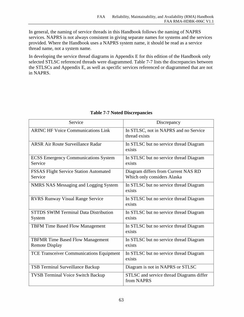
FAA Reliability, Maintainability, and Availability (RMA) Handbook
FAA RMA-HDBK-006C V1.1
63
In general, the naming of service threads in this Handbook follows the naming of NAPRS
services. NAPRS is not always consistent in giving separate names for systems and the services
provided. Where the Handbook uses a NAPRS system name, it should be read as a service
thread name, not a system name.
In developing the service thread diagrams in Appendix E for this edition of the Handbook only
selected STLSC referenced threads were diagrammed. Table 7-7 lists the discrepancies between
the STLSCs and Appendix E, as well as specific services referenced or diagrammed that are not
in NAPRS.
Table 7-7 Noted Discrepancies
Service Discrepancy
ARINC HF Voice Communications Link In STLSC, not in NAPRS and no Service
thread exists
ARSR Air Route Surveillance Radar In STLSC but no service thread Diagram
exists
ECSS Emergency Communications System
Service
In STLSC but no service thread Diagram
exists
FSSAS Flight Service Station Automated
Service
Diagram differs from Current NAS RD
Which only considers Alaska
NMRS NAS Messaging and Logging System In STLSC but no service thread Diagram
exists
RVRS Runway Visual Range Service In STLSC but no service thread Diagram
exists
STTDS SWIM Terminal Data Distribution
System
In STLSC but no service thread Diagram
exists
TBFM Time Based Flow Management In STLSC but no service thread Diagram
exists
TBFMR Time Based Flow Management
Remote Display
In STLSC but no service thread Diagram
exists
TCE Transceiver Communications Equipment In STLSC but no service thread Diagram
exists
TSB Terminal Surveillance Backup Diagram is not in NAPRS or STLSC
TVSB Terminal Voice Switch Backup STLSC and service thread Diagrams differ
from NAPRS
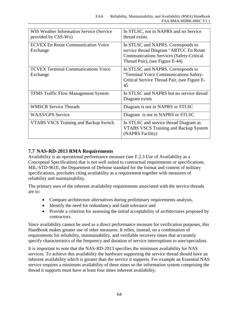
FAA Reliability, Maintainability, and Availability (RMA) Handbook
FAA RMA-HDBK-006C V1.1
64
WIS Weather Information Service (Service
provided by CSS-Wx)
In STLSC, not in NAPRS and no Service
thread exists
ECVEX En Route Communication Voice
Exchange
In STLSC and NAPRS. Corresponds to
service thread Diagram “ARTCC En Route
Communications Services (Safety-Critical
Thread Pair), (see Figure E-44)
TCVEX Terminal Communications Voice
Exchange
In STLSC and NAPRS. Corresponds to
“Terminal Voice Communications Safety-
Critical Service Thread Pair, (see Figure E-
45
TFMS Traffic Flow Management System In STLSC and NAPRS but no service thread
Diagram exists
WMSCR Service Threads Diagram is not in NAPRS or STLSC
WAAS/GPS Service Diagram is not in NAPRS or STLSC
VTABS VSCS Training and Backup Switch In STLSC and service thread Diagram as
VTABS VSCS Training and Backup System
(NAPRS Facility)
7.7 NAS-RD-2013 RMA Requirements Availability is an operational performance measure (see F.2.3 Use of Availability as a
Conceptual Specification) that is not well suited to contractual requirements or specifications.
MIL-STD-961E, the Department of Defense standard for the format and content of military
specifications, precludes citing availability as a requirement together with measures of
reliability and maintainability.
The primary uses of the inherent availability requirements associated with the service threads
are to:
Compare architecture alternatives during preliminary requirements analysis,
Identify the need for redundancy and fault tolerance and
Provide a criterion for assessing the initial acceptability of architectures proposed by
contractors.
Since availability cannot be used as a direct performance measure for verification purposes, this
Handbook makes greater use of other measures. It relies, instead, on a combination of
requirements for reliability, maintainability, and verifiable recovery times that accurately
specify characteristics of the frequency and duration of service interruptions to user/specialists.
It is important to note that the NAS-RD-2013 specifies the minimum availability for NAS
services. To achieve this availability the hardware supporting the service thread should have an
inherent availability which is greater than the service it supports. For example an Essential NAS
service requires a minimum availability of three nines so the information system comprising the
thread it supports must have at least four nines inherent availability.
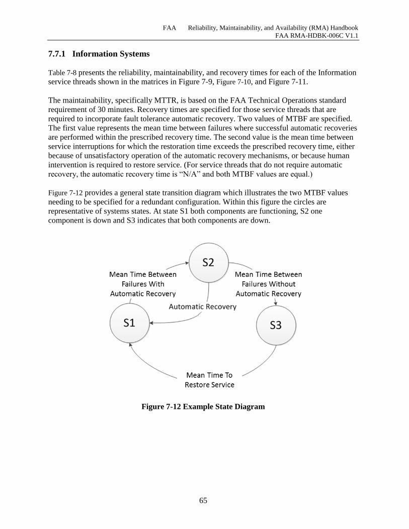
FAA Reliability, Maintainability, and Availability (RMA) Handbook
FAA RMA-HDBK-006C V1.1
65
7.7.1 Information Systems
Table 7-8 presents the reliability, maintainability, and recovery times for each of the Information
service threads shown in the matrices in Figure 7-9, Figure 7-10, and Figure 7-11.
The maintainability, specifically MTTR, is based on the FAA Technical Operations standard
requirement of 30 minutes. Recovery times are specified for those service threads that are
required to incorporate fault tolerance automatic recovery. Two values of MTBF are specified.
The first value represents the mean time between failures where successful automatic recoveries
are performed within the prescribed recovery time. The second value is the mean time between
service interruptions for which the restoration time exceeds the prescribed recovery time, either
because of unsatisfactory operation of the automatic recovery mechanisms, or because human
intervention is required to restore service. (For service threads that do not require automatic
recovery, the automatic recovery time is “N/A” and both MTBF values are equal.)
Figure 7-12 provides a general state transition diagram which illustrates the two MTBF values
needing to be specified for a redundant configuration. Within this figure the circles are
representative of systems states. At state S1 both components are functioning, S2 one
component is down and S3 indicates that both components are down.
Figure 7-12 Example State Diagram
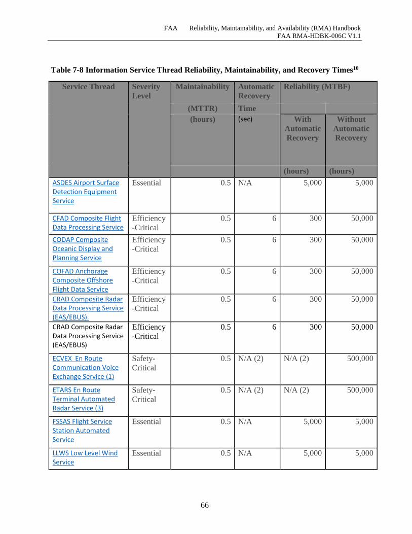
FAA Reliability, Maintainability, and Availability (RMA) Handbook
FAA RMA-HDBK-006C V1.1
66
Table 7-8 Information Service Thread Reliability, Maintainability, and Recovery Times10
Service Thread Severity
Level
Maintainability Automatic
Recovery
Reliability (MTBF)
(MTTR) Time
(hours) (sec) With
Automatic
Recovery
Without
Automatic
Recovery
(hours) (hours)
ASDES Airport Surface Detection Equipment Service
Essential 0.5 N/A 5,000 5,000
CFAD Composite Flight Data Processing Service
Efficiency
-Critical
0.5 6 300 50,000
CODAP Composite Oceanic Display and Planning Service
Efficiency
-Critical
0.5 6 300 50,000
COFAD Anchorage Composite Offshore Flight Data Service
Efficiency
-Critical
0.5 6 300 50,000
CRAD Composite Radar Data Processing Service (EAS/EBUS).
Efficiency
-Critical
0.5 6 300 50,000
CRAD Composite Radar Data Processing Service (EAS/EBUS)
Efficiency
-Critical
0.5 6 300 50,000
ECVEX En Route Communication Voice Exchange Service (1)
Safety-
Critical
0.5 N/A (2) N/A (2) 500,000
ETARS En Route Terminal Automated Radar Service (3)
Safety-
Critical
0.5 N/A (2) N/A (2) 500,000
FSSAS Flight Service Station Automated Service
Essential 0.5 N/A 5,000 5,000
LLWS Low Level Wind Service
Essential 0.5 N/A 5,000 5,000
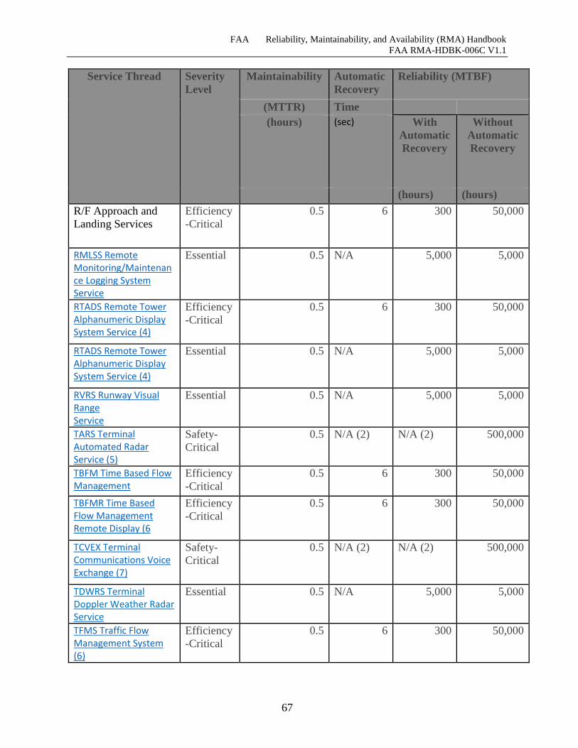
FAA Reliability, Maintainability, and Availability (RMA) Handbook
FAA RMA-HDBK-006C V1.1
67
Service Thread Severity
Level
Maintainability Automatic
Recovery
Reliability (MTBF)
(MTTR) Time
(hours) (sec) With
Automatic
Recovery
Without
Automatic
Recovery
(hours) (hours)
R/F Approach and
Landing Services
Efficiency
-Critical
0.5 6 300 50,000
RMLSS Remote Monitoring/Maintenance Logging System Service
Essential 0.5 N/A 5,000 5,000
RTADS Remote Tower Alphanumeric Display System Service (4)
Efficiency
-Critical
0.5 6 300 50,000
RTADS Remote Tower Alphanumeric Display System Service (4)
Essential 0.5 N/A 5,000 5,000
RVRS Runway Visual Range Service
Essential 0.5 N/A 5,000 5,000
TARS Terminal Automated Radar Service (5)
Safety-
Critical
0.5 N/A (2) N/A (2) 500,000
TBFM Time Based Flow Management
Efficiency
-Critical
0.5 6 300 50,000
TBFMR Time Based Flow Management Remote Display (6
Efficiency
-Critical
0.5 6 300 50,000
TCVEX Terminal Communications Voice Exchange (7)
Safety-
Critical
0.5 N/A (2) N/A (2) 500,000
TDWRS Terminal Doppler Weather Radar Service
Essential 0.5 N/A 5,000 5,000
TFMS Traffic Flow Management System (6)
Efficiency
-Critical
0.5 6 300 50,000
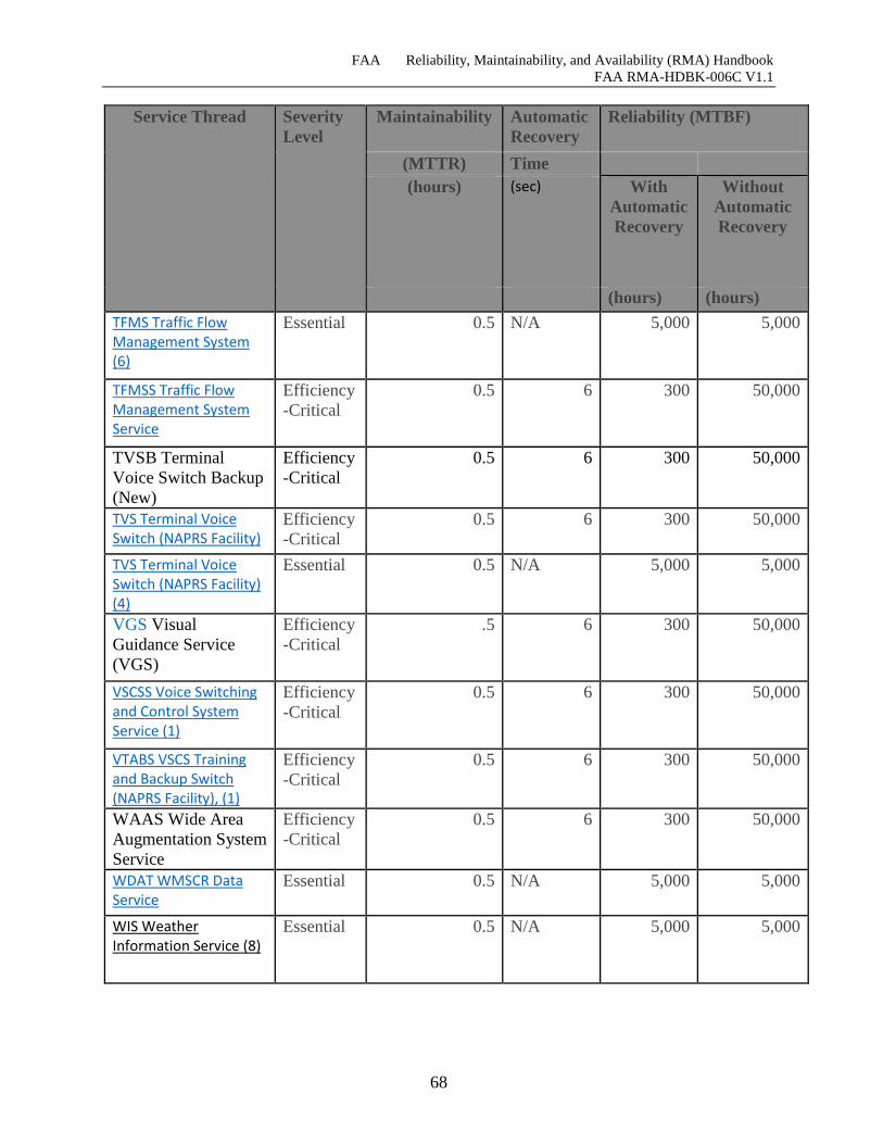
FAA Reliability, Maintainability, and Availability (RMA) Handbook
FAA RMA-HDBK-006C V1.1
68
Service Thread Severity
Level
Maintainability Automatic
Recovery
Reliability (MTBF)
(MTTR) Time
(hours) (sec) With
Automatic
Recovery
Without
Automatic
Recovery
(hours) (hours)
TFMS Traffic Flow Management System (6)
Essential 0.5 N/A 5,000 5,000
TFMSS Traffic Flow Management System Service
Efficiency
-Critical
0.5 6 300 50,000
TVSB Terminal
Voice Switch Backup
(New)
Efficiency
-Critical
0.5 6 300 50,000
TVS Terminal Voice Switch (NAPRS Facility)
Efficiency
-Critical
0.5 6 300 50,000
TVS Terminal Voice Switch (NAPRS Facility) (4)
Essential 0.5 N/A 5,000 5,000
VGS Visual
Guidance Service
(VGS)
Efficiency
-Critical
.5 6 300 50,000
VSCSS Voice Switching and Control System Service (1)
Efficiency
-Critical
0.5 6 300 50,000
VTABS VSCS Training and Backup Switch (NAPRS Facility), (1)
Efficiency
-Critical
0.5 6 300 50,000
WAAS Wide Area
Augmentation System
Service
Efficiency
-Critical
0.5 6 300 50,000
WDAT WMSCR Data Service
Essential 0.5 N/A 5,000 5,000
WIS Weather Information Service (8)
Essential 0.5 N/A 5,000 5,000
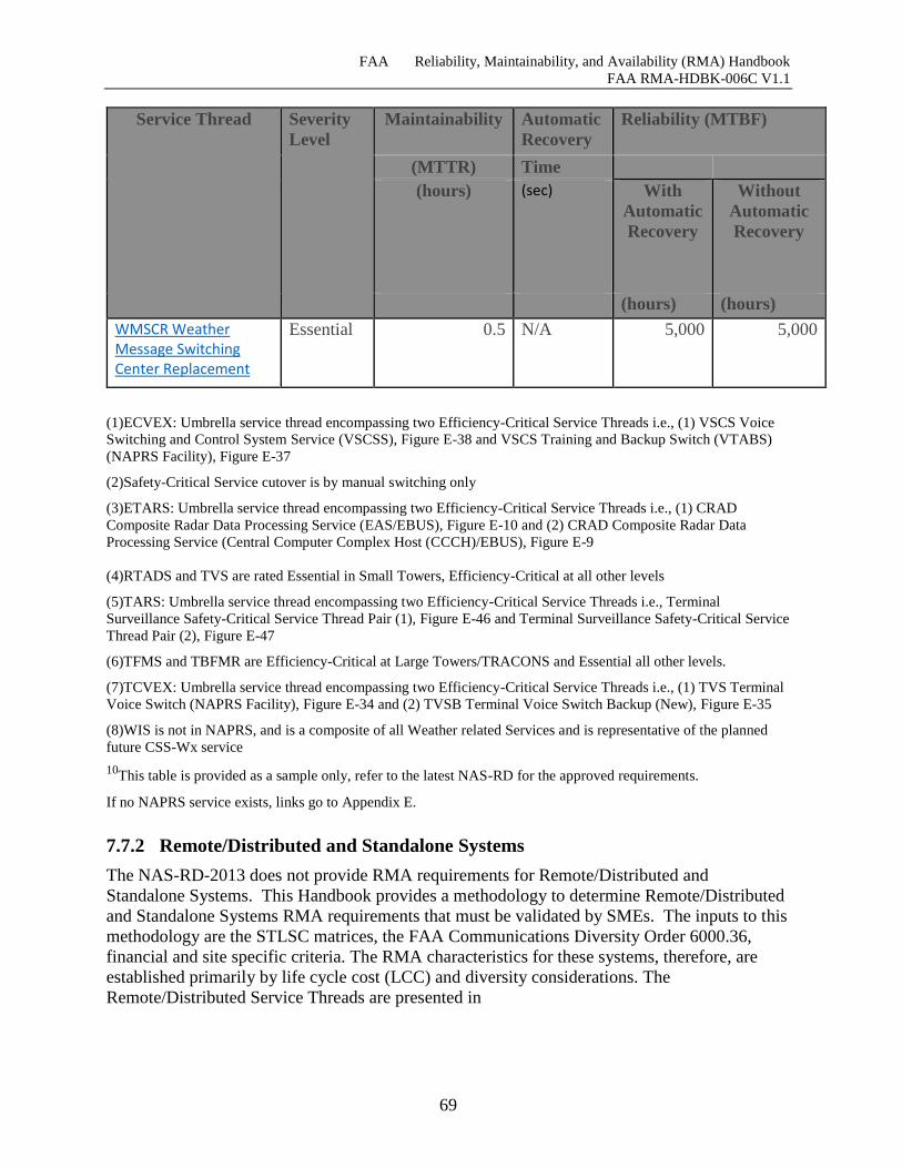
FAA Reliability, Maintainability, and Availability (RMA) Handbook
FAA RMA-HDBK-006C V1.1
69
Service Thread Severity
Level
Maintainability Automatic
Recovery
Reliability (MTBF)
(MTTR) Time
(hours) (sec) With
Automatic
Recovery
Without
Automatic
Recovery
(hours) (hours)
WMSCR Weather Message Switching Center Replacement
Essential 0.5 N/A 5,000 5,000
(1)ECVEX: Umbrella service thread encompassing two Efficiency-Critical Service Threads i.e., (1) VSCS Voice
Switching and Control System Service (VSCSS), Figure E-38 and VSCS Training and Backup Switch (VTABS)
(NAPRS Facility), Figure E-37
(2)Safety-Critical Service cutover is by manual switching only
(3)ETARS: Umbrella service thread encompassing two Efficiency-Critical Service Threads i.e., (1) CRAD
Composite Radar Data Processing Service (EAS/EBUS), Figure E-10 and (2) CRAD Composite Radar Data
Processing Service (Central Computer Complex Host (CCCH)/EBUS), Figure E-9
(4)RTADS and TVS are rated Essential in Small Towers, Efficiency-Critical at all other levels
(5)TARS: Umbrella service thread encompassing two Efficiency-Critical Service Threads i.e., Terminal
Surveillance Safety-Critical Service Thread Pair (1), Figure E-46 and Terminal Surveillance Safety-Critical Service
Thread Pair (2), Figure E-47
(6)TFMS and TBFMR are Efficiency-Critical at Large Towers/TRACONS and Essential all other levels.
(7)TCVEX: Umbrella service thread encompassing two Efficiency-Critical Service Threads i.e., (1) TVS Terminal
Voice Switch (NAPRS Facility), Figure E-34 and (2) TVSB Terminal Voice Switch Backup (New), Figure E-35
(8)WIS is not in NAPRS, and is a composite of all Weather related Services and is representative of the planned
future CSS-Wx service
10This table is provided as a sample only, refer to the latest NAS-RD for the approved requirements.
If no NAPRS service exists, links go to Appendix E.
7.7.2 Remote/Distributed and Standalone Systems
The NAS-RD-2013 does not provide RMA requirements for Remote/Distributed and
Standalone Systems. This Handbook provides a methodology to determine Remote/Distributed
and Standalone Systems RMA requirements that must be validated by SMEs. The inputs to this
methodology are the STLSC matrices, the FAA Communications Diversity Order 6000.36,
financial and site specific criteria. The RMA characteristics for these systems, therefore, are
established primarily by life cycle cost (LCC) and diversity considerations. The
Remote/Distributed Service Threads are presented in
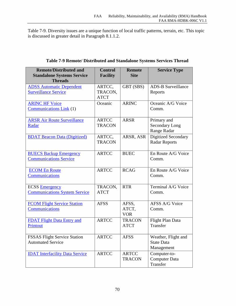
FAA Reliability, Maintainability, and Availability (RMA) Handbook
FAA RMA-HDBK-006C V1.1
70
Table 7-9. Diversity issues are a unique function of local traffic patterns, terrain, etc. This topic
is discussed in greater detail in Paragraph 8.1.1.2.
Table 7-9 Remote/ Distributed and Standalone Systems Services Thread
Remote/Distributed and
Standalone Systems Service
Threads
Control
Facility
Remote
Site
Service Type
ADSS Automatic Dependent
Surveillance Service
ARTCC,
TRACON,
ATCT
GBT (SBS) ADS-B Surveillance
Reports
ARINC HF Voice
Communications Link (1)
Oceanic ARINC Oceanic A/G Voice
Comm.
ARSR Air Route Surveillance
Radar
ARTCC
TRACON
ARSR Primary and
Secondary Long
Range Radar
BDAT Beacon Data (Digitized)
ARTCC,
TRACON
ARSR, ASR Digitized Secondary
Radar Reports
BUECS Backup Emergency
Communications Service
ARTCC BUEC En Route A/G Voice
Comm.
ECOM En Route
Communications
ARTCC RCAG En Route A/G Voice
Comm.
ECSS Emergency
Communications System Service
TRACON,
ATCT
RTR Terminal A/G Voice
Comm.
FCOM Flight Service Station
Communications
AFSS AFSS,
ATCT,
VOR
AFSS A/G Voice
Comm.
FDAT Flight Data Entry and
Printout
ARTCC TRACON
ATCT
Flight Plan Data
Transfer
FSSAS Flight Service Station
Automated Service
ARTCC AFSS Weather, Flight and
State Data
Management
IDAT Interfacility Data Service
ARTCC ARTCC
TRACON
Computer-to-
Computer Data
Transfer
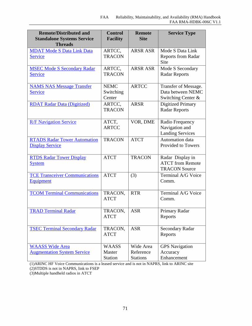
FAA Reliability, Maintainability, and Availability (RMA) Handbook
FAA RMA-HDBK-006C V1.1
71
Remote/Distributed and
Standalone Systems Service
Threads
Control
Facility
Remote
Site
Service Type
MDAT Mode S Data Link Data
Service
ARTCC,
TRACON
ARSR ASR Mode S Data Link
Reports from Radar
Site
MSEC Mode S Secondary Radar
Service
ARTCC,
TRACON
ARSR ASR Mode S Secondary
Radar Reports
NAMS NAS Message Transfer
Service
NEMC
Switching
Center
ARTCC Transfer of Message.
Data between NEMC
Switching Center &
ARTCC NAMS
Concentrator RDAT Radar Data (Digitized)
ARTCC,
TRACON
ARSR Digitized Primary
Radar Reports
R/F Navigation Service ATCT,
ARTCC
VOR, DME Radio Frequency
Navigation and
Landing Services
RTADS Radar Tower Automation
Display Service
TRACON ATCT Automation data
Provided to Towers
RTDS Radar Tower Display
System
ATCT TRACON Radar Display in
ATCT from Remote
TRACON Source
TCE Transceiver Communications
Equipment
ATCT (3) Terminal A/G Voice
Comm.
TCOM Terminal Communications
TRACON,
ATCT
RTR Terminal A/G Voice
Comm.
TRAD Terminal Radar
TRACON,
ATCT
ASR Primary Radar
Reports
TSEC Terminal Secondary Radar
TRACON,
ATCT
ASR Secondary Radar
Reports
WAASS Wide Area
Augmentation System Service
WAASS
Master
Station
Wide Area
Reference
Stations
GPS Navigation
Accuracy
Enhancement
(1)ARINC HF Voice Communications is a leased service and is not in NAPRS, link to ARINC site
(2)STDDS is not in NAPRS, link to FSEP
(3)Multiple handheld radios in ATCT
FAA Reliability, Maintainability, and Availability (RMA) Handbook
FAA RMA-HDBK-006C V1.1
72
7.7.3 Infrastructure and Enterprise Systems
Infrastructure and Enterprise Systems provide power, the environment, communications and
enterprise infrastructure to the facilities. Within the system of systems taxonomy in Figure 7-1,
there are four subcategories of Infrastructure System types defined: Power, HVAC,
Communications Transport and Enterprise Infrastructure Systems. The scope of the systems
included in the Infrastructure Systems category is limited to those systems that provide power,
environment, communications and enterprise infrastructure services to the facilities that house
the information systems. As a result, Infrastructure & Enterprise Systems can cause failures of
the systems they support, such that traditional allocation methods and the assumption of
independence of failures do not apply to them.
Section 7.7.3 defines RMA approaches to Infrastructure and Enterprise Systems to support NAS
service availability. Applicable standards, orders and references are listed in this section to
provide guidance to the practitioner in the specification of RMA requirements for Infrastructure
and Enterprise Systems.
7.7.3.1 Power Systems The RMA requirements for power systems, as defined in the STLSC matrices, are based on the
STLSCs of the threads they support as well as the facility level in which they are installed. All
ARTCCs have the same RMA requirements and the same power architecture. The inherent
availability requirements for Critical Power Distribution Systems (CPDS) are derived from the
NAS-RD-2013 severity requirements for NAS Services/Functions.
In the Terminal domain, there is a wide range of traffic levels between the largest facilities and
the smallest facilities. At larger terminal facilities, the service thread loss severity is comparable
to that of ARTCCs and the severity requirements are the same. Loss of service threads resulting
from power interruptions can have a critical effect on air traffic efficiency as operational
personnel reduce capacity to maintain safe separation. This could increase safety hazards to
unacceptable levels during the transition to manual procedures.
The power system architecture codes used in the matrices were derived from FAA Order
6950.2D, Electrical Power Policy Implementation at National Airspace System Facilities. This
order contains design standards and operating procedures for power systems to ensure power
system availability consistent with the severities of the service threads supported by the power
services.
However at smaller terminal facilities, manual procedures can be invoked without a significant
impact on either safety or efficiency. Accordingly, the severity ratings of these facilities can be
reduced from those applied to the larger facilities.
Inherent availability requirements should in no way be interpreted to be an indication of the
predicted operational performance of a CPDS. The primary purpose of these requirements is
simply to establish whether a dual path redundant architecture is required or whether a less
expensive radial CPDS architecture is adequate for smaller terminal facilities.
In order to meet the severity requirements, dual path architectures have been employed. The
power for Safety-Critical Service Thread pairs should be partitioned across the dual power paths
such that failure of one power path will not cause the failure of both service threads in the
Safety-Critical Service Thread pair.
FAA Reliability, Maintainability, and Availability (RMA) Handbook
FAA RMA-HDBK-006C V1.1
73
For smaller facilities, such as those using commercial power with a simple Engine Generator or
battery backup, there is no allocation of NAS-RD-2013 RMA requirements. Although CPDS
architectures can be tailored to meet inherent availability requirements through the application
of redundancy, there is no such flexibility in simple single path architectures using commercial-
off-the-shelf (COTS) components. Accordingly, for these systems, only the configuration will
be specified using the Power Source Codes defined in FAA Order 6950.2D; no NAS-RD-2013
allocated inherent availability requirements are imposed on the acquisition of COTS power
system components. The reliability and maintainability of COTS components shall be in
accordance with best commercial practices.
The power system requirements for Terminal facilities are presented in Figure 7-13 (in which
standard power system configurations meeting these requirements have been established). The
standards for power systems are contained in FAA Order 6950.2D. The table indicates that the
larger facilities require a dual path redundant CPDS architecture that is capable of meeting the
.999998 inherent availability requirement. Smaller facilities can use single path CPDS
architecture capable of meeting .9998 inherent availability. The smallest facilities do not require
a CPDS architecture and use the specified power system architecture code with no NAS-RD-
2013 allocated availability requirement. Figure 7-14 and
Figure 7-15 “Other” Power System present the power system requirements for En Route
facilities and “Other” (non-operational) facilities respectively.
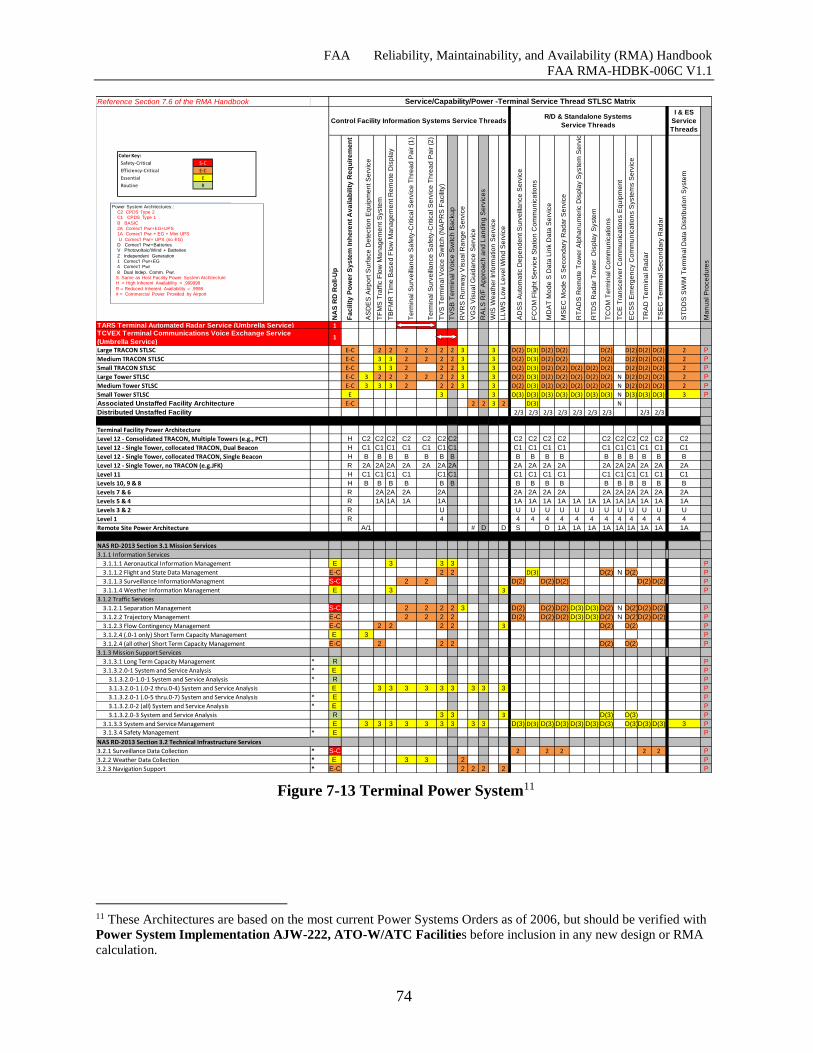
FAA Reliability, Maintainability, and Availability (RMA) Handbook
FAA RMA-HDBK-006C V1.1
74
Figure 7-13 Terminal Power System11
11 These Architectures are based on the most current Power Systems Orders as of 2006, but should be verified with
Power System Implementation AJW-222, ATO-W/ATC Facilities before inclusion in any new design or RMA
calculation.
Reference Section 7.6 of the RMA Handbook
I & ES
Service
Threads
NA
S R
D R
oll-U
p
Fa
cilit
y P
ow
er
Sy
ste
m In
he
ren
t A
va
ila
bilit
y R
eq
uir
em
en
t
AS
DE
S A
irp
ort
Su
rfa
ce
De
tectio
n E
qu
ipm
en
t S
erv
ice
TF
MS
Tra
ffic
Flo
w M
an
ag
em
en
t S
yste
m
TB
FM
R T
ime
Ba
se
d F
low
Ma
na
ge
me
nt R
em
ote
Dis
pla
y
Te
rmin
al S
urv
eill
an
ce
Sa
fety
-Critica
l S
erv
ice
Th
rea
d P
air (
1)
Te
rmin
al S
urv
eill
an
ce
Sa
fety
-Critica
l S
erv
ice
Th
rea
d P
air (
2)
TV
S T
erm
ina
l V
oic
e S
witch
(N
AP
RS
Fa
cili
ty)
TV
SB
Te
rmin
al V
oic
e S
witch
Ba
cku
p
RV
RS
Ru
nw
ay V
isu
al R
an
ge
Se
rvic
e
VG
S V
isu
al G
uid
an
ce
Se
rvic
e
RA
LS
R/F
Ap
pro
ach
an
d L
an
din
g S
erv
ice
s
WIS
We
ath
er
Info
rma
tio
n S
erv
ice
LL
WS
Lo
w L
eve
l W
ind
Se
rvic
e
AD
SS
Au
tom
atic D
ep
en
de
nt S
urv
eill
an
ce
Se
rvic
e
FC
OM
Flig
ht S
erv
ice
Sta
tio
n C
om
mu
nic
atio
ns
MD
AT
Mo
de
S D
ata
Lin
k D
ata
Se
rvic
e
MS
EC
Mo
de
S S
eco
nd
ary
Ra
da
r S
erv
ice
RT
AD
S R
em
ote
To
we
r A
lph
an
um
eric D
isp
lay S
yste
m S
erv
ice
RT
DS
Ra
da
r T
ow
er
Dis
pla
y S
yste
m
TC
OM
Te
rmin
al C
om
mu
nic
atio
ns
TC
E T
ran
sce
ive
r C
om
mu
nic
atio
ns E
qu
ipm
en
t
EC
SS
Em
erg
en
cy C
om
mu
nic
atio
ns S
yste
ms S
erv
ice
TR
AD
Te
rmin
al R
ad
ar
TS
EC
Te
rmin
al S
eco
nd
ary
Ra
da
r
ST
DD
S S
WIM
Te
rmin
al D
ata
Dis
trib
utio
n S
yste
m
Ma
nu
al P
roce
du
res
1
1
E-C 2 2 2 2 2 2 3 3 D(2) D(3) D(2) D(2) D(2) D(2) D(2) D(2) 2 P
E-C 3 3 2 2 2 2 3 3 D(2) D(3) D(2) D(2) D(2) D(2) D(2) D(2) 2 P
E-C 3 3 2 2 2 3 3 D(2) D(3) D(2) D(2) D(2) D(2) D(2) D(2) D(2) D(2) 2 P
E-C 3 2 2 2 2 2 2 3 3 D(2) D(3) D(2) D(2) D(2) D(2) D(2) N D(2) D(2) D(2) 2 P
E-C 3 3 3 2 2 2 3 3 D(2) D(3) D(2) D(2) D(2) D(2) D(2) N D(2) D(2) D(2) 2 P
E 3 3 D(3) D(3) D(3) D(3) D(3) D(3) D(3) N D(3) D(3) D(3) 3 P
E-C 2 2 3 2 D(3) N
2/3 2/3 2/3 2/3 2/3 2/3 2/3 2/3 2/3
Terminal Facility Power Architecture
Level 12 - Consolidated TRACON, Multiple Towers (e.g., PCT) H C2 C2 C2 C2 C2 C2 C2 C2 C2 C2 C2 C2 C2 C2 C2 C2C2 C2
Level 12 - Single Tower, collocated TRACON, Dual Beacon H C1 C1 C1 C1 C1 C1 C1 C1 C1 C1 C1 C1 C1 C1 C1 C1C1 C1
Level 12 - Single Tower, collocated TRACON, Single Beacon H B B B B B B B B B B B B B B B B B B
Level 12 - Single Tower, no TRACON (e.g.JFK) R 2A 2A 2A 2A 2A 2A 2A 2A 2A 2A 2A 2A 2A 2A 2A 2A2A 2A
Level 11 H C1 C1 C1 C1 C1 C1 C1 C1 C1 C1 C1 C1 C1 C1 C1C1 C1
Levels 10, 9 & 8 H B B B B B B B B B B B B B B B B B
Levels 7 & 6 R 2A 2A 2A 2A 2A 2A 2A 2A 2A 2A 2A 2A 2A2A 2A
Levels 5 & 4 R 1A 1A 1A 1A 1A 1A 1A 1A 1A 1A 1A 1A 1A 1A 1A1A 1A
Levels 3 & 2 R U U U U U U U U U U U U U U
Level 1 R 4 4 4 4 4 4 4 4 4 4 4 4 4
Remote Site Power Architecture A/1 # D D S D 1A 1A 1A 1A 1A 1A 1A 1A1A 1A
3.1.1 Information Services
3.1.1.1 Aeronautical Information Management E 3 3 3 P
3.1.1.2 Flight and State Data Management E-C 2 2 D(3) D(2) N D(2) P
3.1.1.3 Surveillance InformationManagment S-C 2 2 D(2) D(2) D(2) D(2) D(2) P
3.1.1.4 Weather Information Management E 3 3 P
3.1.2 Traffic Services
3.1.2.1 Separation Management S-C 2 2 2 2 3 D(2) D(2) D(2) D(3) D(3) D(2) N D(2)D(2) D(2) P
3.1.2.2 Trajectory Management E-C 2 2 2 2 D(2) D(2) D(2) D(3) D(3) D(2) N D(2)D(2) D(2) P
3.1.2.3 Flow Contingency Management E-C 2 2 2 2 3 D(2) D(2) P
3.1.2.4 (.0-1 only) Short Term Capacity Management E 3 P
3.1.2.4 (all other) Short Term Capacity Management E-C 2 2 2 D(2) D(2) P
3.1.3 Mission Support Services
3.1.3.1 Long Term Capacity Management * R P
3.1.3.2.0-1 System and Service Analysis * E P
3.1.3.2.0-1.0-1 System and Service Analysis * R P
3.1.3.2.0-1 (.0-2 thru.0-4) System and Service Analysis E 3 3 3 3 3 3 3 3 3 P
3.1.3.2.0-1 (.0-5 thru.0-7) System and Service Analysis * E P
3.1.3.2.0-2 (all) System and Service Analysis * E P
3.1.3.2.0-3 System and Service Analysis R 3 3 3 D(3) D(3) P
3.1.3.3 System and Service Management E 3 3 3 3 3 3 3 3 3 D(3) D(3) D(3) D(3) D(3) D(3) D(3) D(3)D(3) D(3) 3 P
3.1.3.4 Safety Management * E P
3.2.1 Surveillance Data Collection * S-C 2 2 2 2 2 P
3.2.2 Weather Data Collection * E 3 3 2 P
3.2.3 Navigation Support * E-C 2 2 2 2 P
Small Tower STLSC
Associated Unstaffed Facility Architecture
Distributed Unstaffed Facility
NAS RD-2013 Section 3.1 Mission Services
Service/Capability/Power -Terminal Service Thread STLSC Matrix
Control Facility Information Systems Service ThreadsR/D & Standalone Systems
Service Threads
TARS Terminal Automated Radar Service (Umbrella Service)TCVEX Terminal Communications Voice Exchange Service
(Umbrella Service)
Large TRACON STLSC
Medium TRACON STLSC
Small TRACON STLSC
NAS RD-2013 Section 3.2 Technical Infrastructure Services
Large Tower STLSC
Medium Tower STLSC
Color Key:
Safety-Critical S-C
Efficiency-Critical E-C
Essential E
Routine R
Power System Architectures::C2 CPDS Type 2 C1 CPDS Type 1
B BASIC 2A Comec'l Pwr+EG+UPS1A Comec'l Pwr + EG + Mini UPS
U Comec'l Pwr+ UPS (no EG)D Comec'l Pwr+BatteriesV Photovoltaic/Wind + Batteries
Z Independent Generation1 Comec'l Pwr+EG4 Comec'l Pwr
8 Dual Indep. Comm. Pwr. S Same as Host Facility Power System ArchitectureH = High Inherent Availability = .999998
R = Reduced Inherent Availability = .9998# = Commercial Power Provided by Airport
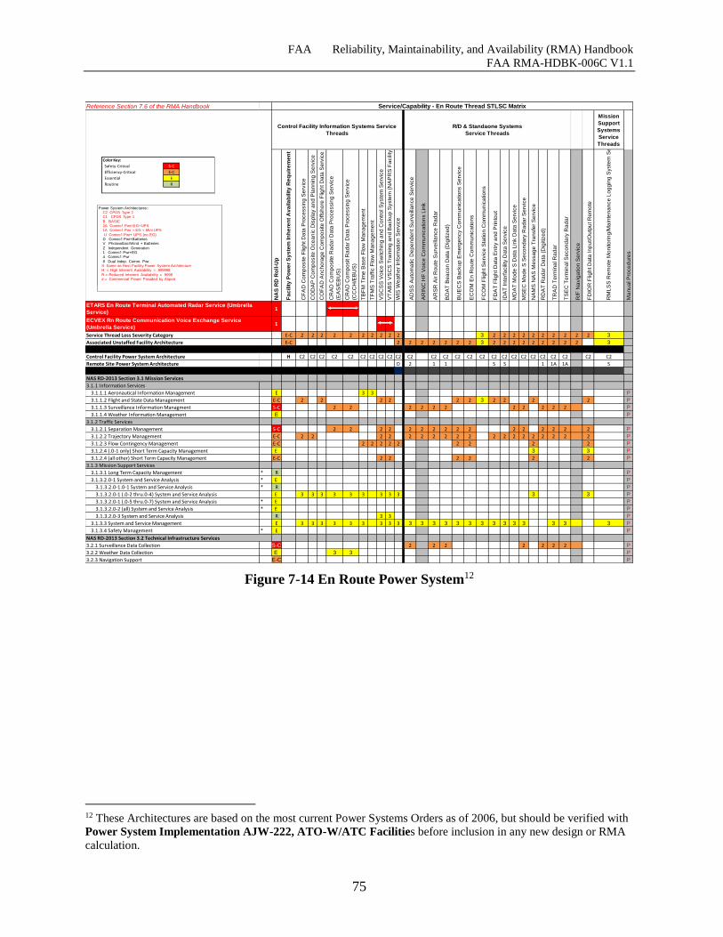
FAA Reliability, Maintainability, and Availability (RMA) Handbook
FAA RMA-HDBK-006C V1.1
75
Figure 7-14 En Route Power System12
12 These Architectures are based on the most current Power Systems Orders as of 2006, but should be verified with
Power System Implementation AJW-222, ATO-W/ATC Facilities before inclusion in any new design or RMA
calculation.
Reference Section 7.6 of the RMA Handbook
Mission
Support
Systems
Service
Threads
NA
S R
D R
oll-U
p
Fa
cilit
y P
ow
er
Sy
ste
m In
he
ren
t A
va
ila
bilit
y R
eq
uir
em
en
t
CF
AD
Co
mp
osite
Flig
ht D
ata
Pro
ce
ssin
g S
erv
ice
CO
DA
P C
om
po
site
Oce
an
ic D
isp
lay a
nd
Pla
nn
ing
Se
rvic
e
CO
FA
D A
nch
ora
ge
Co
mp
osite
Offsh
ore
Flig
ht D
ata
Se
rvic
e
CR
AD
Co
mp
osite
Ra
da
r D
ata
Pro
ce
ssin
g S
erv
ice
(EA
S/E
BU
S)
CR
AD
Co
mp
osit R
ad
ar
Da
ta P
roce
ssin
g S
erv
ice
(CC
CH
/EB
US
)
TB
FM
Tim
e B
ase
Flo
w M
an
ag
em
en
t
TF
MS
Tra
ffic
Flo
w M
an
ag
em
en
t
VS
CS
S V
oic
e S
witch
ing
an
d C
on
tro
l S
yste
m S
erv
ice
VT
AB
S V
SC
S T
rain
ing
an
d B
acku
p S
yste
m (
NA
PR
S F
acili
ty)
WIS
We
ath
er
Info
rma
tio
n S
erv
ice
AD
SS
Au
tom
atic D
ep
en
de
nt S
urv
eill
an
ce
Se
rvic
e
AR
INC
HF
Vo
ice
Co
mm
un
ica
tio
ns L
ink
AR
SR
Air R
ou
te S
urv
eill
an
ce
Ra
da
r
BD
AT
Be
aco
n D
ata
(D
igitiz
ed
)
BU
EC
S B
acku
p E
me
rge
ncy C
om
mu
nic
atio
ns S
erv
ice
EC
OM
En
Ro
ute
Co
mm
un
ica
tio
ns
FC
OM
Flig
ht S
erv
ice
Sta
tio
n C
om
mu
nic
atio
ns
FD
AT
Flig
ht D
ata
En
try a
nd
Prin
tou
t
IDA
T In
terf
acili
ty D
ata
Se
rvic
e
MD
AT
Mo
de
S D
ata
Lin
k D
ata
Se
rvic
e
MS
EC
Mo
de
S S
eco
nd
ary
Ra
da
r S
erv
ice
NA
MS
NA
S M
essa
ge
Tra
nsfe
r S
erv
ice
RD
AT
Ra
da
r D
ata
(D
igitiz
ed
)
TR
AD
Te
rmin
al R
ad
ar
TS
EC
Te
rmin
al S
eco
nd
ary
Ra
da
r
R/F
Na
vig
atio
n S
erv
ice
FD
IOR
Flig
ht D
ata
In
pu
t/O
utp
ut R
em
ote
RM
LS
S R
em
ote
Mo
nito
rin
g/M
ain
ten
an
ce
Lo
gg
ing
Syste
m S
erv
ice
Ma
nu
al P
roce
du
res
1
1
E-C 2 2 2 2 2 2 2 2 2 2 3 2 2 2 2 2 2 2 2 2 2 3
E-C 2 2 2 2 2 2 2 3 2 2 2 2 2 2 2 2 2 3
Control Facility Power System Architecture H C2 C2 C2 C2 C2 C2 C2 C2 C2 C2 C2 C2 C2 C2 C2 C2 C2 C2 C2 C2 C2 C2 C2 C2 C2 C2
Remote Site Power System Architecture D 2 1 1 S S 1 1A 1A S
3.1.1 Information Services
3.1.1.1 Aeronautical Information Management E 3 3 P
3.1.1.2 Flight and State Data Management E-C 2 2 2 2 2 2 3 2 2 2 2 P
3.1.1.3 Surveillance Information Managment S-C 2 2 2 2 2 2 2 2 2 2 2 P
3.1.1.4 Weather Information Management E P
3.1.2 Traffic Services
3.1.2.1 Separation Management S-C 2 2 2 2 2 2 2 2 2 2 2 2 2 2 2 2 P
3.1.2.2 Trajectory Management E-C 2 2 2 2 2 2 2 2 2 2 2 2 2 2 2 2 2 2 2 P
3.1.2.3 Flow Contingency Management E-C 2 2 2 2 2 2 2 2 2 P
3.1.2.4 (.0-1 only) Short Term Capacity Management E 3 3 P
3.1.2.4 (all other) Short Term Capacity Management E-C 2 2 2 2 2 2 P
3.1.3 Mission Support Services
3.1.3.1 Long Term Capacity Management * R P
3.1.3.2.0-1 System and Service Analysis * E P
3.1.3.2.0-1.0-1 System and Service Analysis * R P
3.1.3.2.0-1 (.0-2 thru.0-4) System and Service Analysis E 3 3 3 3 3 3 3 3 3 3 3 P
3.1.3.2.0-1 (.0-5 thru.0-7) System and Service Analysis * E P
3.1.3.2.0-2 (all) System and Service Analysis * E P
3.1.3.2.0-3 System and Service Analysis R 3 3 P
3.1.3.3 System and Service Management E 3 3 3 3 3 3 3 3 3 3 3 3 3 3 3 3 3 3 3 3 3 3 3 P
3.1.3.4 Safety Management * E P
3.2.1 Surveillance Data Collection S-C 2 2 2 2 2 2 2 P
3.2.2 Weather Data Collection E 3 3 P
3.2.3 Navigation Support E-C P
NAS RD-2013 Section 3.2 Technical Infrastructure Services
Service/Capability - En Route Thread STLSC Matrix
Control Facility Information Systems Service
Threads
R/D & Standaone Systems
Service Threads
ETARS En Route Terminal Automated Radar Service (Umbrella
Service)
ECVEX Rn Route Communication Voice Exchange Service
(Umbrella Service)
Service Thread Loss Severity Category
Associated Unstaffed Facility Architecture
NAS RD-2013 Section 3.1 Mission Services
Color Key:
Safety-Critical S-C
Efficiency-Critical E-C
Essential E
Routine R
Power System Architectures::C2 CPDS Type 2 C1 CPDS Type 1
B BASIC 2A Comec'l Pwr+EG+UPS1A Comec'l Pwr + EG + Mini UPS
U Comec'l Pwr+ UPS (no EG)D Comec'l Pwr+BatteriesV Photovoltaic/Wind + Batteries
Z Independent Generation1 Comec'l Pwr+EG4 Comec'l Pwr
8 Dual Indep. Comm. Pwr. S Same as Host Facility Power System ArchitectureH = High Inherent Availability = .999998
R = Reduced Inherent Availability = .9998# = Commercial Power Provided by Airport
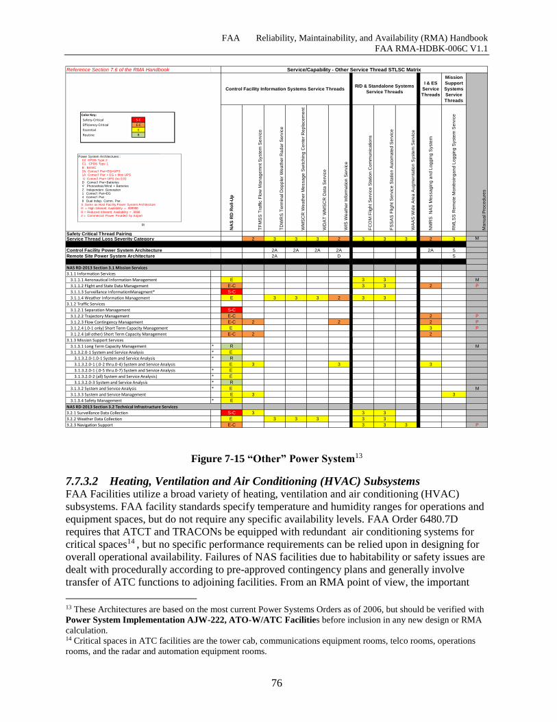
FAA Reliability, Maintainability, and Availability (RMA) Handbook
FAA RMA-HDBK-006C V1.1
76
Figure 7-15 “Other” Power System13
7.7.3.2 Heating, Ventilation and Air Conditioning (HVAC) Subsystems FAA Facilities utilize a broad variety of heating, ventilation and air conditioning (HVAC)
subsystems. FAA facility standards specify temperature and humidity ranges for operations and
equipment spaces, but do not require any specific availability levels. FAA Order 6480.7D
requires that ATCT and TRACONs be equipped with redundant air conditioning systems for
critical spaces14 , but no specific performance requirements can be relied upon in designing for
overall operational availability. Failures of NAS facilities due to habitability or safety issues are
dealt with procedurally according to pre-approved contingency plans and generally involve
transfer of ATC functions to adjoining facilities. From an RMA point of view, the important
13 These Architectures are based on the most current Power Systems Orders as of 2006, but should be verified with
Power System Implementation AJW-222, ATO-W/ATC Facilities before inclusion in any new design or RMA
calculation. 14 Critical spaces in ATC facilities are the tower cab, communications equipment rooms, telco rooms, operations
rooms, and the radar and automation equipment rooms.
Reference Section 7.6 of the RMA Handbook
I & ES
Service
Threads
Mission
Support
Systems
Service
Threads
NA
S R
D R
oll-U
p
TF
MS
S T
raffic
Flo
w M
an
ag
em
nt S
yste
m S
erv
ice
TD
WR
S T
erm
ina
l D
op
ple
r W
ea
the
r R
ad
ar
Se
rvic
e
WM
SC
R W
ea
the
r M
essa
ge
Sw
itch
ing
Ce
nte
r R
ep
lace
me
nt
WD
AT
WM
SC
R D
ata
Se
rvic
e
WIS
We
ath
er
Info
rma
tio
n S
erv
ice
FC
OM
Flig
ht S
erv
ice
Sta
tio
n C
om
mu
nic
atio
ns
FS
SA
S F
ligh
t S
erv
ice
Sta
tio
n A
uto
ma
ted
Se
rvic
e
WA
AS
Wid
e A
rea
Au
gm
en
tatio
n S
yste
m S
erv
ice
NM
RS
N
AS
Me
ssa
gin
g a
nd
Lo
gg
ing
Syste
m
RM
LS
S R
em
ote
Mo
nitro
ing
an
d L
og
gin
g S
yste
m S
erv
ice
Ma
nu
al P
roce
du
res
2 3 3 3 2 3 3 3 2 3 M
Control Facility Power System Architecture 2A 2A 2A 2A 2A S
Remote Site Power System Architecture 2A D S
3.1.1 Information Services
3.1.1.1 Aeronautical Information Management E 3 3 M
3.1.1.2 Flight and State Data Management E-C 3 3 2 P
3.1.1.3 Surveillance InformationManagment* S-C
3.1.1.4 Weather Information Management E 3 3 3 2 3 3
3.1.2 Traffic Services
3.1.2.1 Separation Management S-C
3.1.2.2 Trajectory Management E-C 2 P
3.1.2.3 Flow Contingency Management E-C 2 2 2 P
3.1.2.4 (.0-1 only) Short Term Capacity Management E 3 P
3.1.2.4 (all other) Short Term Capacity Management E-C 2 2
3.1.3 Mission Support Services
3.1.3.1 Long Term Capacity Management * R M
3.1.3.2.0-1 System and Service Analysis * E
3.1.3.2.0-1.0-1 System and Service Analysis * R
3.1.3.2.0-1 (.0-2 thru.0-4) System and Service Analysis E 3 3 3
3.1.3.2.0-1 (.0-5 thru.0-7) System and Service Analysis * E
3.1.3.2.0-2 (all) System and Service Analysis) * E
3.1.3.2.0-3 System and Service Analysis * R
3.1.3.2 System and Service Analysis * E M
3.1.3.3 System and Service Management E 3 3
3.1.3.4 Safety Management * E
3.2.1 Surveillance Data Collection S-C 3 3 3
3.2.2 Weather Data Collection E 3 3 3 3 3
3.2.3 Navigation Support E-C 3 3 3 P
Service/Capability - Other Service Thread STLSC Matrix
R/
Control Facility Information Systems Service ThreadsR/D & Standalone Systems
Service Threads
Safety Critical Thread PairingService Thread Loss Severity Category
NAS RD-2013 Section 3.1 Mission Services
NAS RD-2013 Section 3.2 Technical Infrastructure Services
Color Key:
Safety-Critical S-C
Efficiency-Critical E-C
Essential E
Routine R
Power System Architectures::C2 CPDS Type 2 C1 CPDS Type 1
B BASIC 2A Comec'l Pwr+EG+UPS1A Comec'l Pwr + EG + Mini UPS
U Comec'l Pwr+ UPS (no EG)D Comec'l Pwr+BatteriesV Photovoltaic/Wind + Batteries
Z Independent Generation1 Comec'l Pwr+EG4 Comec'l Pwr
8 Dual Indep. Comm. Pwr. S Same as Host Facility Power System ArchitectureH = High Inherent Availability = .999998
R = Reduced Inherent Availability = .9998# = Commercial Power Provided by Airport
FAA Reliability, Maintainability, and Availability (RMA) Handbook
FAA RMA-HDBK-006C V1.1
77
HVAC failure or degradation consideration is to prevent immediate failure of Safety-Critical
services. Design of systems contributing to Safety-Critical services should fail gracefully in
event of cooling/heating loss. For example they should not automatically shut down on
detecting loss of coolant airflow. System designers should be aware of facility Contingency
Plans and design for degradation with the "Transition Hazard Interval", as shown in Figure 7-4,
in mind.
7.7.3.3 Enterprise Infrastructure Enterprise Infrastructure consists of the enterprise networks, systems and services required to
provide a NAS service. Similar to power systems, enterprise infrastructure is required to support
NAS services and NAS service threads at facilities. Unlike power systems, these networks,
systems and services are distributed across geographic regions, extending well beyond the
facility and provide the communications and information framework needed to support NAS
services nationally.
The following subsections provide a background on these networks, systems and services and
the relevance to RMA as well as the challenges associated with acquisition and implementation.
A RMA approach and methodology for enterprise infrastructure is presented supplementing
what is defined in Section 6.
7.7.3.3.1 Overview of Enterprise Infrastructure Systems
Efforts are underway to implement Enterprise Infrastructure Systems to support new and
existing NAS Services. Many new services are being introduced, and existing capabilities and
services are being migrated to Enterprise Infrastructure Systems based on Service-Oriented
Architectures (SOAs) and Cloud-computing technologies.[48][76]
The following sections provide background information on SOA, Cloud-Computing, and
discussions on challenges associated with implementing these technologies and in Section
7.7.3.3.3, derives the RMA requirements for EIS.
7.7.3.3.1.1 Service-Oriented Architecture SOA is a platform design pattern that standardizes hosting and orchestration of a distributed set
of published services which facilitates software reuse across platforms. The FAA is
transitioning to a Service-Oriented Architecture (SOA) under the FAA System-Wide
Information Management (SWIM) Program. [77] The purpose of SWIM is to improve
enterprise information sharing across the NAS. The following is a list of key SOA enabling
components currently being implemented by the SWIM program:
Services Registry: Services will be published within the NAS Service Registry /
Repository (NSRR) Universal Description, Discovery and Integration (UDDI)
Registry.[44]
o All Services typically register with the UDDI.
o Consumer Services find Producer Services via a UDDI (SWIM will use publish /
subscribe web services approach).
o The Orchestration Engine relies on the UDDI registry in order to determine if the
services to be orchestrated are registered and available.
FAA Reliability, Maintainability, and Availability (RMA) Handbook
FAA RMA-HDBK-006C V1.1
78
Enterprise Messaging and Communications: The NAS Enterprise Messaging Service
(NEMS) Message Brokers and Enterprise Service Bus (ESB) will be used for Enterprise
Messaging. FTI provides the physical links to support SWIM messaging.[44]
Governance: SWIM will be responsible for the governance and orchestration of services.
Services will be orchestrated as a part of a work flow.
Information on SWIM standards and documentation can be found on the SWIM website:
http://www.faa.gov/about/office_org/headquarters_offices/ato/service_units/techops/atc_comms
_services/swim/
The following list outlines the challenges associated with migrating NAS services to a SOA:
Implementing Enterprise Information Management will most likely require distributed
data information architecture. The SWIM Terminal Data Distribution System (STDDS)
is an example of this architecture. This may require some form of distributed data
registry and repository beyond the SWIM Service Registry.
SWIM plans for a reliable and durable messaging framework through NEMS. Systems
planning to utilize SOA messaging solutions need to include requirements for NEMS
messaging as well as the ability for the maintainer to diagnose problems in message
delivery between services.
Dependency on several core services for operation. These include messaging services,
interface management, enterprise service management, system security and enterprise
governance. Reliability and maintainability requirements need to be specified for these
services, including MTTR and MTBF values as well as known approaches to improve
reliability and maintenance of SOA core components.
Potential for single-points of vulnerability and long-recovery times. As a result,
requirements need to be specified which mitigate single-points of vulnerability, such that
NAS systems and services can continue to operate, maintaining the ability to
communicate, process and publish / consume information in the absence of these SOA
core components.
Increased message size and message processing leads to increased latencies and impacts
service availability. The RMA practitioner needs to consider the impact of the
messaging protocol, content, possible link speeds and whether or not the overall latency
requirement and the availability for the NAS service can be maintained.
Traditionally, RMA efforts have focused on inherent availability and increasing SW reliability
to reduce a system’s MTBF. Employing redundancy and utilizing fault tolerance techniques
allows systems to achieve higher availabilities. As a result, MTBF has improved dramatically
for Safety-Critical, Efficiency-Critical and Essential NAS services. Further, the introduction of
independent service threads, redundant systems, and fault tolerant software has facilitated
meeting high availability requirements for Safety-Critical applications. These approaches will
need to be carried forward and applied to these new Enterprise Infrastructure Systems and
enterprise services which provide these levels of NAS services. Further, due to the complexity
and demonstrated reliability of implemented SOAs and Cloud-Computing, recovery approaches
will need to be specified in order to minimize MTTR, in addition to improving reliability, such
that the necessary availability can be achieved.
FAA Reliability, Maintainability, and Availability (RMA) Handbook
FAA RMA-HDBK-006C V1.1
79
7.7.3.3.1.2 Cloud Architectures Cloud-computing is a utility computing model which leverages virtualization in
implementation, where resources are provisioned and used only when they are required and
where resources may be procured as a service and used on an as-needed basis.
Cloud service providers offer products in a number of categories and configurations. Cloud
service offerings are typically categorized by the architectural layers accessed by the user with
designations such as IaaS, PaaS, SaaS and others. The FAA is already utilizing a Cloud service
for email in a configuration that is classified as Software as a Service (SaaS). Elements of the
SWIM program are implemented as a Cloud software platform and are categorized as Platform
as a Service (PaaS). Implementation or re-hosting of NAS systems in the Cloud could also be
done at the VM level and would be categorized as being implemented on Infrastructure as a
Service (IaaS). Other configurations and forms of service are offered or may be offered in the
future, but it is incumbent on the system designer to thoroughly understand both the architecture
and contractual aspects of the service offering in designing for availability.
Cloud offerings are also categorized by the physical and logical locations and user populations
of the Cloud. The National Institutes of Standards and Technology (NIST) categorize Clouds as
Private, Public, Community, or Hybrid. As the names imply, a Private Cloud is dedicated to a
single customer and does not share resources beyond the customer’s contracted or owned
boundaries. A Public Cloud on the other hand offers services to a range of unaffiliated
customers and is likely to share resources (compute, storage and network) among all users. A
Community Cloud is a restricted Public Cloud in which the Cloud population is restricted to an
agreed or understood limited set of customers. A Cloud sharing service among aviation related
users for collaboration would be an example. A Hybrid Cloud is a Cloud that provides for
automated migration or expansion of services between Private and Public Clouds based on
demand or other factors. As with service offerings, the system designer must make choices that
will impact on availability when choosing a Cloud type. Security is a major consideration for
Cloud applications and becomes a factor in RMA considerations, both due to exposure to non-
technical risks to availability as well as the impact of increased complexity.
Cloud-hosted applications, services and infrastructure can support high-availability and
redundancy by providing clustered general purpose processing, network, and storage resources.
However, the design and implementation of software or service redundancy features is usually
left to the system designer and not implemented transparently by the vendor. Well-designed
Cloud-Computing architectures can be resilient and can support the geographic distribution of
storage and processing, such that applications and services can be supported across multiple
sites in cases of contingency and continuity of operations as a result of man-made or natural
disasters.
A Cloud architecture typically consists of:
A clustered set of servers which support load-balancing as well as automated failover of
virtual machines.
A hypervisor operating system, which is an operating system running on each server
within the cluster to host virtual machines (Windows, Linux, etc.), Virtual Machine -
hosted applications (such as SWIM Core services) and virtual applications.
FAA Reliability, Maintainability, and Availability (RMA) Handbook
FAA RMA-HDBK-006C V1.1
80
A converged network supporting user traffic, storage area network and Cloud
management traffic. This includes communications between clustered servers at the
hypervisor level to manage failover and virtual machine (VM) restarts.
Network-based storage (SAN)
o Supports hosting of VM images and supports rapid automated failover of hosted
VMs by exposing that VM to multiple servers in a cluster.
o Supports operating system (OS) management, such as the hypervisor OS.
A Cloud management, provisioning and orchestration layer consisting of hardware,
hypervisor OS and virtual machines, hosted applications, and services management.
Security overlay supporting access controls, compartmentalization of data and
processing.
There are challenges in allocating RMA requirements to enterprise Cloud-Computing systems
and services since,
These systems are complex, distributed real-time systems which utilize existing COTS
information technology hardware and software not specifically designed to meet NAS
requirements.
Cloud-computing services may be outsourced to a large commercial service provider
with associated Service-Level Agreements (SLAs).
When Clouds fail, there are potentially long recovery times and data loss. Implemented
Clouds consist of layers for management, hardware (servers, network, and storage),
hypervisor OS, VMs and applications. If a Cloud fails, recovery times tend to be very
long because it takes time to restore operations at each level of the Cloud and orchestrate
restoration such that the environment may be recovered and recertified for operation. As
a result, geographically separated primary, backup and disaster recovery sites are
typically required to support both contingency and business continuity operations.
However, there have been several highly publicized cases in commercial industry where
unknown single points of vulnerability existed which led to all sites failing and outages
lasting hours or even days due to long recovery times.[46] As a result, care must be
taken in adopting new technologies to support new and existing NAS Services.
These difficulties in implementing NAS services with SOA and Cloud-Computing do not
alleviate the need for the NAS service to meet the availability requirements for services
described in NAS-RD-2013. In the following sections, RMA approaches are described, which
leverage these new technologies, services, and architectural approaches such that NAS
availability requirements can be achieved.
7.7.3.3.2 Communications Transport
The FAA is transitioning to Internet Protocol (IP) communications architecture and is leasing
services where RMA characteristics are incorporated in SLAs. In designing systems employing
both inter and intra-facility communications, the designer must now take into account both FAA
Order 6000.36 "Communications Diversity" [57] which specifies route diversity design
approaches for typical NAPRS Services, and selection of appropriate SLA options. In
specifying the Communications Transport requirements for a new service the characteristics of
a number of new or planned FAA systems and services should be taken into account.
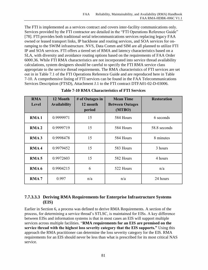
FAA Reliability, Maintainability, and Availability (RMA) Handbook
FAA RMA-HDBK-006C V1.1
81
The FTI is implemented as a services contract and covers inter-facility communications only.
Services provided by the FTI contractor are detailed in the “FTI Operations Reference Guide”
[78]. FTI provides both traditional serial telecommunications services replacing legacy FAA
owned or leased transport links, IP backbone and routing services, and SOA services for on-
ramping to the SWIM infrastructure. NVS, Data Comm and SIM are all planned to utilize FTI
IP and SOA services. FTI offers a tiered set of RMA and latency characteristics based on a
SLA, with diversity and avoidance routing options based on the requirements of FAA Order
6000.36. While FTI RMA characteristics are not incorporated into service thread availability
calculations, system designers should be careful to specify the FTI RMA service class
appropriate to the service thread requirements. The RMA characteristics of FTI services are set
out in in Table 7.1 of the FTI Operations Reference Guide and are reproduced here in Table
7-10. A comprehensive listing of FTI services can be found in the FAA Telecommunications
Services Description (FTSD), Attachment J.1 to the FTI contract DTFA01-02-D-03006.
Table 7-10 RMA Characteristics of FTI Services
RMA
Level
12 Month
Availability
# of Outages in
12 month
period
Mean Time
Between Outages
(MTBO)
Restoration
RMA 1 0.9999971 15 584 Hours 6 seconds
RMA 2 0.9999719 15 584 Hours 58.8 seconds
RMA 3 0.9998478 15 584 Hours 8 minutes
RMA 4 0.9979452 15 583 Hours 3 hours
RMA 5 0.9972603 15 582 Hours 4 hours
RMA 6 0.9904215 6 522 Hours n/a
RMA 7 0.997 n/a n/a 24 hours
7.7.3.3.3 Deriving RMA Requirements for Enterprise Infrastructure Systems
(EIS)
Earlier in Section 6, a process was defined to derive RMA Requirements. A section of the
process, for determining a service thread’s STLSC, is maintained for EISs. A key difference
between EISs and information systems is that in most cases an EIS will support multiple
services across multiple facilities. “RMA requirements for an EIS are premised on the
service thread with the highest loss severity category that the EIS supports.” Using this
approach the RMA practitioner can determine the loss severity category for the EIS. RMA
requirements for an EIS should never be less than what is prescribed for its most critical NAS
service.
FAA Reliability, Maintainability, and Availability (RMA) Handbook
FAA RMA-HDBK-006C V1.1
82
Several considerations must be made before appropriate RMA requirements can be specified for
an EIS. First, the impact of losing a service at a larger facility, such as a TRACON with a
Facility Level of 9 through 12, may require the practitioner to specify a more reliable EIS
architecture. For existing service threads the STLSC is scaled based on facility level and the
value is provided within the STLSC matrices Figure 7-9, Figure 7-10, and Figure 7-11. In
addition to facility level, it is important that the RMA practitioner consider the effects of the
concentration of services which results if an EIS is utilized to support numerous services. A
Service Risk Assessment (SRA) is useful to study the effects of concentrated services. One
method of increasing service reliability is to specify higher Communications Transport service
levels. In addition to increased Communications Transport availability there are various
methods for increasing availability discussed in Section 7.7.3.3.4.
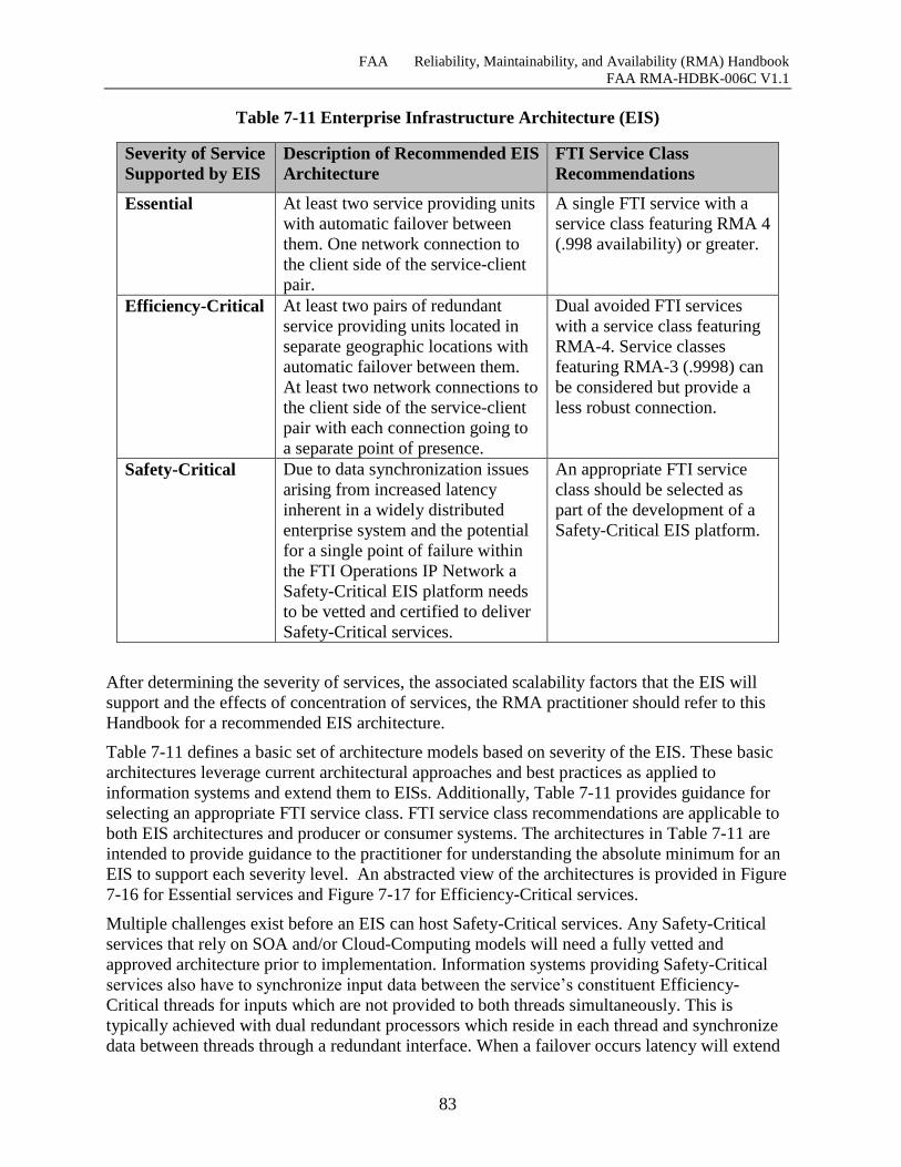
FAA Reliability, Maintainability, and Availability (RMA) Handbook
FAA RMA-HDBK-006C V1.1
83
Table 7-11 Enterprise Infrastructure Architecture (EIS)
Severity of Service
Supported by EIS
Description of Recommended EIS
Architecture
FTI Service Class
Recommendations
Essential At least two service providing units
with automatic failover between
them. One network connection to
the client side of the service-client
pair.
A single FTI service with a
service class featuring RMA 4
(.998 availability) or greater.
Efficiency-Critical At least two pairs of redundant
service providing units located in
separate geographic locations with
automatic failover between them.
At least two network connections to
the client side of the service-client
pair with each connection going to
a separate point of presence.
Dual avoided FTI services
with a service class featuring
RMA-4. Service classes
featuring RMA-3 (.9998) can
be considered but provide a
less robust connection.
Safety-Critical Due to data synchronization issues
arising from increased latency
inherent in a widely distributed
enterprise system and the potential
for a single point of failure within
the FTI Operations IP Network a
Safety-Critical EIS platform needs
to be vetted and certified to deliver
Safety-Critical services.
An appropriate FTI service
class should be selected as
part of the development of a
Safety-Critical EIS platform.
After determining the severity of services, the associated scalability factors that the EIS will
support and the effects of concentration of services, the RMA practitioner should refer to this
Handbook for a recommended EIS architecture.
Table 7-11 defines a basic set of architecture models based on severity of the EIS. These basic
architectures leverage current architectural approaches and best practices as applied to
information systems and extend them to EISs. Additionally, Table 7-11 provides guidance for
selecting an appropriate FTI service class. FTI service class recommendations are applicable to
both EIS architectures and producer or consumer systems. The architectures in Table 7-11 are
intended to provide guidance to the practitioner for understanding the absolute minimum for an
EIS to support each severity level. An abstracted view of the architectures is provided in Figure
7-16 for Essential services and Figure 7-17 for Efficiency-Critical services.
Multiple challenges exist before an EIS can host Safety-Critical services. Any Safety-Critical
services that rely on SOA and/or Cloud-Computing models will need a fully vetted and
approved architecture prior to implementation. Information systems providing Safety-Critical
services also have to synchronize input data between the service’s constituent Efficiency-
Critical threads for inputs which are not provided to both threads simultaneously. This is
typically achieved with dual redundant processors which reside in each thread and synchronize
data between threads through a redundant interface. When a failover occurs latency will extend
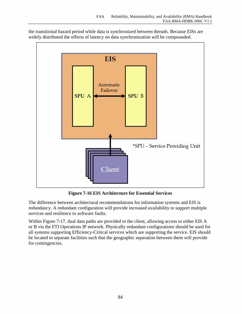
FAA Reliability, Maintainability, and Availability (RMA) Handbook
FAA RMA-HDBK-006C V1.1
84
the transitional hazard period while data is synchronized between threads. Because EISs are
widely distributed the effects of latency on data synchronization will be compounded.
Figure 7-16 EIS Architecture for Essential Services
The difference between architectural recommendations for information systems and EIS is
redundancy. A redundant configuration will provide increased availability to support multiple
services and resilience to software faults.
Within Figure 7-17, dual data paths are provided to the client, allowing access to either EIS A
or B via the FTI Operations IP network. Physically redundant configurations should be used for
all systems supporting Efficiency-Critical services which are supporting the service. EIS should
be located in separate facilities such that the geographic separation between them will provide
for contingencies.
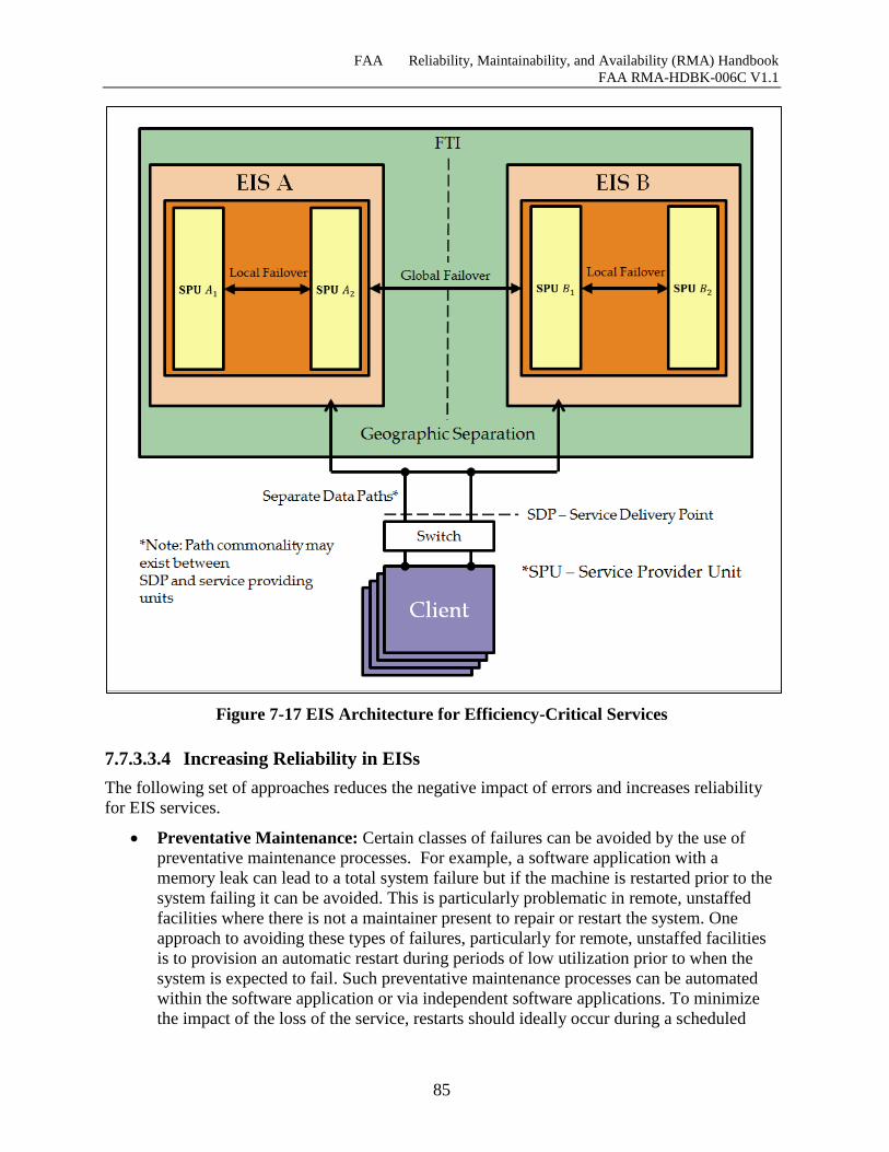
FAA Reliability, Maintainability, and Availability (RMA) Handbook
FAA RMA-HDBK-006C V1.1
85
Figure 7-17 EIS Architecture for Efficiency-Critical Services
7.7.3.3.4 Increasing Reliability in EISs
The following set of approaches reduces the negative impact of errors and increases reliability
for EIS services.
Preventative Maintenance: Certain classes of failures can be avoided by the use of
preventative maintenance processes. For example, a software application with a
memory leak can lead to a total system failure but if the machine is restarted prior to the
system failing it can be avoided. This is particularly problematic in remote, unstaffed
facilities where there is not a maintainer present to repair or restart the system. One
approach to avoiding these types of failures, particularly for remote, unstaffed facilities
is to provision an automatic restart during periods of low utilization prior to when the
system is expected to fail. Such preventative maintenance processes can be automated
within the software application or via independent software applications. To minimize
the impact of the loss of the service, restarts should ideally occur during a scheduled
FAA Reliability, Maintainability, and Availability (RMA) Handbook
FAA RMA-HDBK-006C V1.1
86
outage. Preventive Maintenance is also applicable to hardware components and
improves overall availability.
Recovery Approaches: Recovery approaches are defined below to address cases where
failures are either expected, cannot be prevented, or in cases where software reliability is
unknown. Recovery approaches also address the case where software reliability growth
plans, as described in Appendix A cannot be applied to the system, software, or service
in question.
o Automatic Diagnosis, Operator Intervention: A failing system should aid the
maintainer in determining the source of a hardware failure or software fault. For EIS,
this is difficult, particularly for service threads that span multiple systems and
facilities. As a result, the key to this technique is employing data mining and
software to pinpoint failures based on trace log information, such as failed requests,
failed message transfers, etc. Pinpointing the problem will help aid the maintainers
and the operators in isolating the failure, thus reducing the MTTR.
o Fine Grained Partitioning and Recursive Recovery: This approach applies to
systems that do not tolerate unannounced restarts which result in long downtimes. It
applies to Enterprise Services and software components and assumes that most
software defects can cause software to crash, deadlock, spin, leak memory or
otherwise fail in a way that leaves a reboot or restart as the only option. This
approach can be useful for systems residing in remote, unstaffed facilities for
systems where a maintainer is not present and in cases where system restarts are not
acceptable.
The approach involves partitioning of services, separating stateful software
components in a hierarchical manner such that faults can be isolated, and allows
services or processes to be restarted without the entire system failing. These restarts
can occur periodically, at a time of minimal impact prior to when a failure is
expected to occur, or it can occur upon when the failure is detected. For more
information on this approach and how it could be applied and specified, please refer
to [54].
o Reversible, Undoable Systems: Rapid rollback of updates which are stateful and
persistent is an approach that addresses failures which result from an erroneous input
to the system or an update to the system which causes it to fail. This approach is
typically built into virtualization and storage area network solutions via a snapshot
mechanism which allows the virtualized system and the state to be completely
restored to the point in time that the snapshot was taken. This approach is
recommended for EIS systems with software applications, services and / or operating
systems that are expected to be updated frequently.
o Rapid, Graceful Restart: This approach is applicable in systems where predicted
software reliability is unknown; where there is limited influence on software
reliability growth and where system restarts are tolerated, but not long downtimes.
Several approaches are available, such as machine reboots to a known state or
snapshot. Or a physical machine that is specified and configured to be able to be
FAA Reliability, Maintainability, and Availability (RMA) Handbook
FAA RMA-HDBK-006C V1.1
87
restarted and operational within a short-period of time. These approaches are
typically applied to systems where information is not persisted or stored. However, it
can be applied to services that upon restoration retrieve state data upon restart from
another system.
Redundancy Approaches: In fault-less environments, redundancy is not required.
However, in situations where the level of software reliability is not predictable and the
ability to manage and control software reliability growth is somewhat limited,
redundancy is critical to achieving operational availability for Efficiency-Critical and
Safety-Critical NAS Services.
o Redundancy with Failover: Redundancy is the provisioning of functional capabilities
which act as a backup, which automatically kick-in when a failure is detected. Based
on Section 7.3, redundancy is necessary to meet availability requirements for
systems supporting Efficiency-Critical and Safety-Critical NAS Services. These
redundancy approaches also extend to Enterprise Infrastructure Systems and
Services. Enterprise Services and Systems should be designed to provide stateful
redundancy with rapid failover and potentially hot-standby. State-less redundancy,
i.e. cold-standby, can also be considered for such applications as long as the
switchover time does not impinge on the overall availability goals and when loss of
information is not a concern. This approach can be applied to physical systems
running enterprise software, virtualized systems and software (i.e. VM) and
enterprise services. For example, redundancy could be applied to a UDDI registry
via two virtual machines running on a Cloud. Or the UDDI registry can be extended
to the facility, redundant with the centralized UDDI registry, such that services at
that facility can still discover registered services, should the centralized UDDI
registry go down. In another example, there could be a set of 20 duplicate services
running across multiple physical machines or virtual machines which are redundant
with one another and provide load balancing abilities. All of these examples
provision functional capabilities to act as a backup when failures occur.
o N, N+1 Redundant Systems with Failover: This approach allows the maintainer to
upgrade one system (becoming N+1 baseline), while leaving the backup system
unchanged at the current baseline (N). This approach can also be applied to physical
systems, virtual machines and enterprise services as described in the previous
section.
o Recovery-Oriented Computing (ROC) Approach for Enterprise Infrastructure
Systems: The traditional fault-tolerance community has focused on reducing MTBF
and has occasionally devoted attention to recovery, however the ROC approach “…
focuses on MTTR under the assumption that failures are generally problems that can
be known ahead of time and should be avoided.” [54] ROC assumes that failures
will occur and that software faults are inevitable. ROC takes a more pragmatic
approach by focusing on reducing recovery times in order to increase availability.
The approach takes nothing away from improving MTBF but instead recognizes,
through over a decade of experience in implementing complex enterprise-level
FAA Reliability, Maintainability, and Availability (RMA) Handbook
FAA RMA-HDBK-006C V1.1
88
systems, that significant failures should be expected. By improving MTTR, the
operational availability is improved beyond a MTBF-only approach.
The approach offers a different perspective in planning for failure. Instead of
specifying requirements to fix, avoid, prevent or tolerate failure approaches which
can be extremely expensive to implement, this approach focuses on the recovery of
failures based on priority of impact and specifies approaches that are known to speed
up these recovery times.
For more information on this approach and methodology please consult the
following references. The ROC approach was developed at UC Berkeley (see
reference [54] for approach and rationale) and adopted and expanded by Microsoft
as a part of their Resilience Modeling and Analysis process (see reference [53] for
process, methodology and templates). Further, more references are provided which
should aid in the specification of requirements and in implementation.
7.8 Summary of Process for Deriving RMA Requirements Section 6 of this Handbook summarizes a process for deriving RMA requirements for all areas
of the System of Systems taxonomy. Section 7.1 details the NAS-RD severity assessment
process which assigns a severity level to each of the NAS-RD functional requirements. A
process for developing service threads is provided in Section 7.2 along with the introduction of
the NAS System of Systems taxonomy. Section 7.3 explains how to assess a service thread’s
severity by considering the impact of transitioning to manual backup procedures which are in
place to provide service in the event of a service tread loss. Since the impact of the loss of a
service is not the same for all FAA facilities, Section 7.4 presents a method for scaling a STLSC
based on facility size. Section 7.5 describes the process of assigning STLSCs to service threads.
The following sections, Sections 7.6 and 7.7 assign STLSCs to service threads and explain how
RMA requirements are derived for each area of the taxonomy. Section 7.6 provides STLSC
matrices for each domain of the NAS, Terminal and En-Route. Service threads which do not
reside within a specific domain reside in the “Other” STLSC matrix. RMA characteristics for
Remote/Distributed Service Threads are determined using technical and Lifecycle Cost
considerations, however the STLSC matrices in Section 7.6 provide a starting point for
Remote/Distributed threads. With the necessary background information provided in previous
sections, Section 7.7 begins to discuss the development of RMA requirements for each area of
the taxonomy. This includes requirements for inherent availability, reliability or MTBF. An
approach for deriving RMA requirements for infrastructure and enterprise systems concludes
Section 6. Sample RMA requirements are provided in Appendix A.
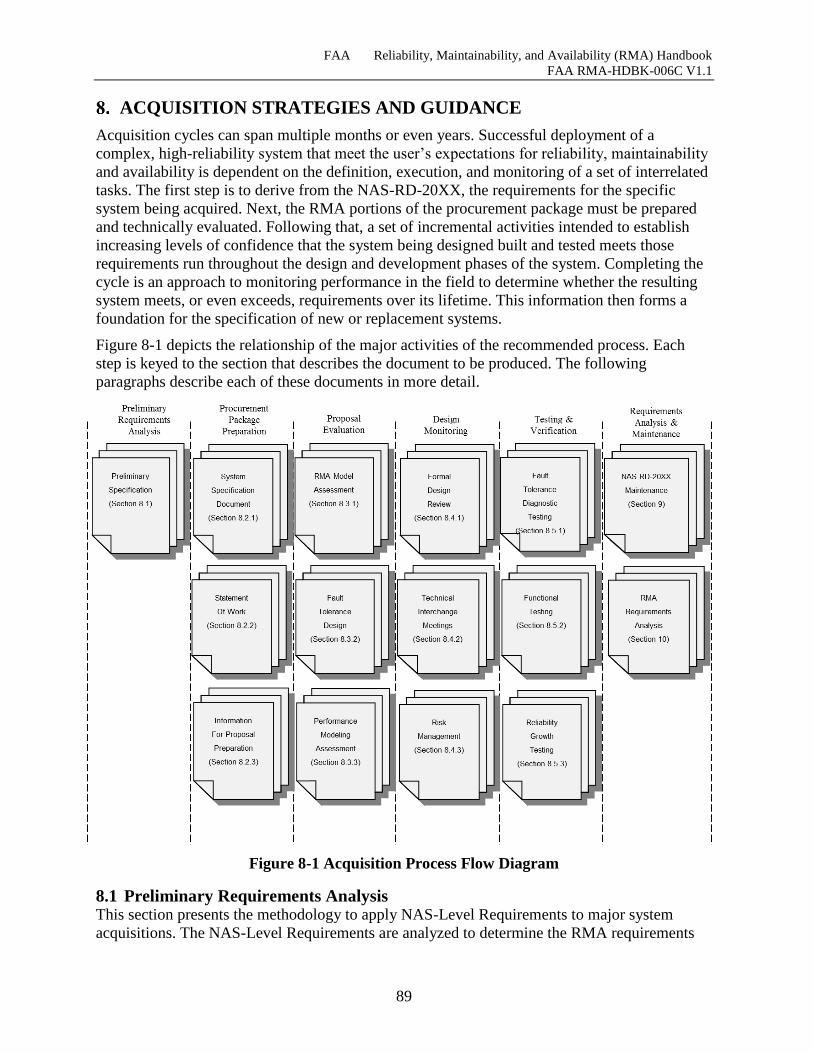
FAA Reliability, Maintainability, and Availability (RMA) Handbook
FAA RMA-HDBK-006C V1.1
89
ACQUISITION STRATEGIES AND GUIDANCE
Acquisition cycles can span multiple months or even years. Successful deployment of a
complex, high-reliability system that meet the user’s expectations for reliability, maintainability
and availability is dependent on the definition, execution, and monitoring of a set of interrelated
tasks. The first step is to derive from the NAS-RD-20XX, the requirements for the specific
system being acquired. Next, the RMA portions of the procurement package must be prepared
and technically evaluated. Following that, a set of incremental activities intended to establish
increasing levels of confidence that the system being designed built and tested meets those
requirements run throughout the design and development phases of the system. Completing the
cycle is an approach to monitoring performance in the field to determine whether the resulting
system meets, or even exceeds, requirements over its lifetime. This information then forms a
foundation for the specification of new or replacement systems.
Figure 8-1 depicts the relationship of the major activities of the recommended process. Each
step is keyed to the section that describes the document to be produced. The following
paragraphs describe each of these documents in more detail.
Figure 8-1 Acquisition Process Flow Diagram
8.1 Preliminary Requirements Analysis This section presents the methodology to apply NAS-Level Requirements to major system
acquisitions. The NAS-Level Requirements are analyzed to determine the RMA requirements
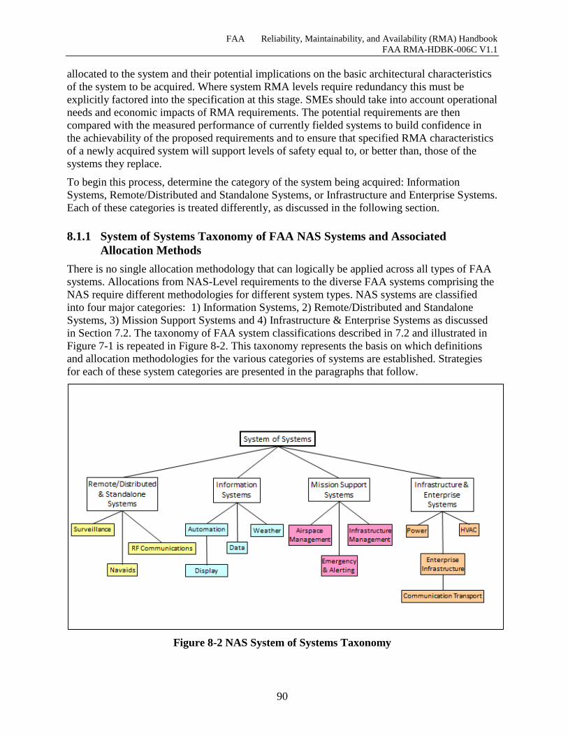
FAA Reliability, Maintainability, and Availability (RMA) Handbook
FAA RMA-HDBK-006C V1.1
90
allocated to the system and their potential implications on the basic architectural characteristics
of the system to be acquired. Where system RMA levels require redundancy this must be
explicitly factored into the specification at this stage. SMEs should take into account operational
needs and economic impacts of RMA requirements. The potential requirements are then
compared with the measured performance of currently fielded systems to build confidence in
the achievability of the proposed requirements and to ensure that specified RMA characteristics
of a newly acquired system will support levels of safety equal to, or better than, those of the
systems they replace.
To begin this process, determine the category of the system being acquired: Information
Systems, Remote/Distributed and Standalone Systems, or Infrastructure and Enterprise Systems.
Each of these categories is treated differently, as discussed in the following section.
8.1.1 System of Systems Taxonomy of FAA NAS Systems and Associated
Allocation Methods
There is no single allocation methodology that can logically be applied across all types of FAA
systems. Allocations from NAS-Level requirements to the diverse FAA systems comprising the
NAS require different methodologies for different system types. NAS systems are classified
into four major categories: 1) Information Systems, 2) Remote/Distributed and Standalone
Systems, 3) Mission Support Systems and 4) Infrastructure & Enterprise Systems as discussed
in Section 7.2. The taxonomy of FAA system classifications described in 7.2 and illustrated in
Figure 7-1 is repeated in Figure 8-2. This taxonomy represents the basis on which definitions
and allocation methodologies for the various categories of systems are established. Strategies
for each of these system categories are presented in the paragraphs that follow.
Figure 8-2 NAS System of Systems Taxonomy
FAA Reliability, Maintainability, and Availability (RMA) Handbook
FAA RMA-HDBK-006C V1.1
91
1. Information Systems are generally computer systems located in major facilities staffed
by Air Traffic Control personnel. These systems consolidate large quantities of
information for use by operational personnel. They usually have high severity and
availability requirements because their failure could affect large volumes of information
and many users. Typically, they employ fault tolerance, redundancy, and automatic fault
detection and recovery to achieve high availability. These systems can be mapped to the
NAS Services and Capabilities functional requirements.
2. The Remote/Distributed and Standalone Systems category includes remote sensors,
communications, and navigation sites – as well as distributed subsystems such as display
terminals – that may be located within a major facility. Failures of single elements, or
even combinations of elements, can degrade performance at an operational facility, but
generally they do not result in the total loss of the surveillance, communications,
navigation, or display capability.
3. Infrastructure & Enterprise Systems provide power, the environment, communications
and enterprise infrastructure to the facilities.
4. Mission Support Systems are the systems used to manage the design, operation and
maintenance of the systems used in the performance of the air traffic control mission.
Remote/Distributed Service Threads achieve the overall availability required by NAS-RD-2013
through the use of qualitative architectural diversity techniques as specified in FAA Order
6000.36. Primarily, these involve multiple instantiations of the service thread with overlapping
coverage. The ensemble of service thread instantiations provides overall continuity of service
despite failures of individual service thread instantiations. The RMA requirements for the
systems and subsystems comprising R/D service threads are determined by the NAS
Requirements Group. Acquisition Managers determine the most cost effective method of
implementation taking into account what is technically achievable and Life Cycle Cost
considerations. Procedures for determining the RMA characteristics of the Power Systems
supplying service threads are discussed in Section 8.1.1.4.
8.1.1.1 Information Systems The starting point for the development of RMA requirements is the set of three matrices
developed in the previous section, Figure 7-9, Figure 7-10, and Figure 7-11. For Information
Systems, select the matrix pertaining to the domain in which a system is being upgraded or
replaced and review the service threads listed in the matrix to determine which service thread(s)
pertain to the system that is being upgraded or replaced.
For systems that are direct replacements for existing systems:
1. Use the Service/Function STLSC matrix to identify the service thread that encompasses
the system being replaced. If more than one service thread is supported by the system,
use the service thread with the highest STLSC value (e.g. the ERAM supports both the
CRAD surveillance service thread and the CFAD flight data processing service thread).
2. Use the severity associated with the highest SLTSC value to determine the appropriate
system severity requirement.
FAA Reliability, Maintainability, and Availability (RMA) Handbook
FAA RMA-HDBK-006C V1.1
92
Use the NAS-RD-20XX requirements presented in Table 7-8 to determine appropriate base-line
MTBF, MTTR, and recovery time (if applicable) values for each of the service threads to ensure
consistency with STLSC severities.
For systems that are not simple replacements of systems contained in existing service threads,
define a new service thread. The appropriate STLSC Matrix for the domain and the service
thread Reliability, Maintainability, and Recovery Times Table, Table 7-8, need to be updated,
and a new Service Thread Diagram needs to be created and included in Appendix E. As
discussed in the preceding section, the practical purpose of the severity is to determine
fundamental system architecture issues such as whether or not fault tolerance and automatic
recovery are required, and to ensure that adequate levels of redundancy will be incorporated into
the system architecture. The primary driver of the actual operational availability will be the
reliability of the software and automatic recovery mechanisms.
8.1.1.2 Remote/Distributed and Standalone Systems This category includes systems with Remote/Distributed and Standalone elements, such as radar
sites, air-to-ground communications sites and navigation aids. These systems are characterized
by their spatial diversity. The surveillance and communications resources for a major facility
such as a TRACON or ARTCC are provided by a number of remote sites. Failure of a remote
site may or may not degrade the overall surveillance, communications, or navigation function,
depending on the degree overlapping coverage, but the service and space diversity of these
remote systems makes total failure virtually impossible.
Attempts have been made in the past to perform a top-down allocation to a subsystem of
distributed elements. To do so requires that a hypothetical failure definition for the subsystem
be defined. For example, the surveillance subsystem could be considered to be down if two out
of fifty radar sites are inoperable. This failure definition is admittedly arbitrary and ignores the
unique characteristics of each installation, including air route structure, geography, overlapping
coverage, etc. Because such schemes rely almost entirely on “r out of n” criteria for subsystem
failure definitions, the availability allocated to an individual element of a Remote/Distributed
and Standalone System may be much lower than that which could be reasonably expected from
a quality piece of equipment.
For these reasons, a top down allocation from NAS requirements to elements comprising a
distributed subsystem is not appropriate, and this category of systems has been isolated as
Remote/Distributed Service Threads in the STLSC matrices in Figure 7-9, Figure 7-10, and
Figure 7-11. STLSC values are listed for Remote/Distributed Service Threads only to provide
RMA practitioners with a starting point for deriving the RMA characteristics of
Remote/Distributed and standalone systems.
The RMA requirements for the individual elements comprising a Remote/Distributed and
Standalone System should be determined by life-cycle cost considerations and the experience of
FAA acquisition specialists in dealing with realistic and achievable requirements. The overall
reliability characteristics of the entire distributed subsystem are achieved through the use of
diversity.
FAA Order 6000.36, “Communication and Surveillance Service Diversity,” establishes the
national guidance to reduce the vulnerability of these Remote/Distributed services to single
points of failure. The order provides for the establishment of regional Communications and
FAA Reliability, Maintainability, and Availability (RMA) Handbook
FAA RMA-HDBK-006C V1.1
93
Surveillance Working Groups (CSWGs) to develop regional communications diversity and
surveillance plans for all ARTCC, pacer airports, other level 5 terminals.
The scope of FAA Order 6000.36 includes communications services and surveillance services.
The NAPRS services to which the order applies are listed in Appendix 1 of the order. They
correspond to the NAPRS services that were mapped to the Remote/Distributed and Standalone
Systems category and designated as supporting critical NAS Architecture Capabilities in the
matrices in Figure 7-9, Figure 7-10, and Figure 7-11.
FAA Order 6000.36 defines five different diversity approaches that may be employed:
1. Service Diversity – services provided via alternate sites; e.g. overlapping radar or
communications coverage.)
2. Route or Circuit Diversity – Physical separation of outside dual route or loop cable
systems.
3. Space Diversity – antennas at different locations.
4. Media Diversity – radio/microwave, public telephone network, satellite, etc.
5. Frequency Diversity – the utilization of different frequencies to achieve diversity in
communications and surveillance.
The type(s) and extent of diversity to be used are to be determined, based on local and regional
conditions, in a bottom-up fashion by communications working groups.
FAA Order 6000.36 tends to support the approach recommended in this Handbook – exempting
Remote/Distributed services and systems from top-down allocation of NAS-RD-2013
availability requirements. The number and placement of the elements should be determined by
FAA specialists knowledgeable in the operational characteristics and requirements for a specific
facility instead of by a mechanical mathematical allocation process. Ensuring that the NAS-
Level severities are not degraded by failures of Remote/Distributed and Standalone Systems in
a service thread can best be achieved through the judicious use of diversity techniques tailored
to the local characteristics of a facility.
The key point in the approach for Remote/Distributed and Standalone Systems is that the path
to achieving NAS-Level availability requirements employs diversity techniques, establishes that
the RMA specifications for individual Remote/Distributed elements are an outgrowth of a
business decision by FAA Service Unit, and that these decisions are based on trade-off analyses
that involve factors such as what is available, what may be achievable, and how increasing
reliability requirements might save on the costs of equipment operation and maintenance.
Distributed display consoles have been included in this category, since the same allocation
rationale has been applied to them. For the same reasons given for remote systems, the
reliability requirements for individual display consoles should be primarily a business decision
determined by life cycle cost tradeoff analyses. The number and placement of consoles should
be determined by operational considerations.
Airport surveillance radars are also included in this category. Even though they are not
distributed like the en route radar sensors, their RMA requirements still should be determined
by life cycle cost tradeoff analyses. Some locations may require more than one radar – based on
the level of operations, geography and traffic patterns – but, as with subsystems with distributed
elements, the decision can best be made by personnel knowledgeable in the unique operational
characteristics of a given facility.
FAA Reliability, Maintainability, and Availability (RMA) Handbook
FAA RMA-HDBK-006C V1.1
94
Navigation systems are remote from the air traffic control facilities and may or may not be
distributed. The VOR navigation system consists of many distributed elements, but an airport
instrument landing system (ILS) does not. Because the service threads are the responsibility of
Air Traffic personnel, NAVAIDS that provide services to aircraft (and not to Air Traffic
personnel) are not included in the NAPRS 6040.15 service threads. Again, RMA requirements
for navigation systems should be determined by life-cycle cost tradeoff analyses, and the
redundancy, overlapping coverage, and placement should be determined on a case-by-case basis
by operational considerations determined by knowledgeable experts.
8.1.1.3 Mission Support Systems Mission Support services used for airspace design and management of the NAS infrastructure
are not generally real-time services and are not reportable services within NAPRS. For these
reasons, it is not appropriate to allocate NAS-RD-20XX availabilities associated with real-time
services used to perform the air traffic control mission to this category of services and systems.
The RMA requirements for the systems and subsystems comprising Mission Support Service
Threads are determined by SMEs and verified by Acquisition Managers in accordance with
what is achievable and Life Cycle Cost considerations.
8.1.1.4 Infrastructure and Enterprise Systems The following four subsections discuss procurement impacts of Infrastructure and Enterprise
Systems including 1) power systems, 2) heating ventilation and air conditioning (HVAC)
systems, 3) Communications Transport and 4) Enterprise Infrastructure Systems (EIS).The
complex interactions of infrastructure systems with the systems they support violate the
independence assumption that is the basis of conventional RMA allocation and prediction. By
their very nature, systems in an air traffic control facility depend on the supporting
infrastructure systems for their continued operation. Failures of infrastructure systems can be a
direct cause of failures in the systems they support.
Moreover, failures of infrastructure services may or may not cause failures in the service threads
they support, and the duration of a failure in the infrastructure service is not necessarily the
same as the duration of the failure in a supported service thread. For example, short power
interruption of less than a second can cause a failure in a computer system that may disrupt
operations for hours. In contrast, an interruption in HVAC service may have no effect at all on
the supported services, provided that HVAC service is restored before environmental conditions
deteriorate beyond what can be tolerated by the systems they support.
Communications Transport services are procured by the FAA on a leased services basis.
Leased services are treated differently than in-house services from the RMA view point.
Communications Transport services are not designed by the FAA, rather they are specified
according to desired performance parameters such as RMA and Diversity/Avoidance.
Enterprise Services constitute yet another subcategory of services from the RMA point of
view. Multiple enterprise services are hosted on an EIS across various facilities with varying
levels of service availability. One or more of those services may be utilized depending on the
service end-user. RMA requirements are dependent on the highest service severity level of the
constituent EIS services. Acquisition managers should utilize SMEs and consider the need for
more stringent RMA requirements due to aggregated services and contingency planning
requirements.
FAA Reliability, Maintainability, and Availability (RMA) Handbook
FAA RMA-HDBK-006C V1.1
95
8.1.1.4.1 Power Systems
Due to the complex interaction of the infrastructure systems with the service threads they
support, top-down allocations of NAS-RD-2013 availability requirements are limited to simple
inherent availability requirements that can be used to determine the structure of the power
system architecture. The allocated power system requirements are shown in Figure 7-13, Figure
7-14, and
Figure 7-15 “Other” Power System. The inherent availability requirement for power systems at
larger facilities is derived from the NAS-RD-2013 requirement of .99999 for Safety-Critical
capabilities. It should be emphasized that these inherent availability requirements serve only to
drive the power system architectures, and should not be considered to be representative of the
predicted operational availability of the power system or the service threads it supports.
At smaller terminal facilities, the inherent availability requirements for the Critical Power
Distribution System can be reduced because the reduced traffic levels at these facilities allow
manual procedures to be used to compensate for power interruptions without causing serious
disruptions in either safety or efficiency of traffic movement.
The smallest terminal facilities do not require a Critical Power Distribution System. The power
systems at these facilities generally consist of commercial power with an engine generator or
battery backup. The availability of these power systems is determined by the availability of the
commercial power system components employed. Allocated NAS-RD-2013 requirements are
not applicable to these systems.
The FAA Power Distribution Systems are developed using standard commercial off-the-shelf
power system components whose RMA characteristics cannot be specified by the FAA. The
RMA characteristics of commercial power system components are documented in IEEE Std
493-1997, Recommended Practice for the Design of Reliable Industrial and Commercial Power
Systems, (Gold Book). This document presents the fundamentals of reliability analysis applied
to the planning and design of electric power distribution systems, and contains a catalog of
commercially available power system components and operational reliability data for the
components. Engineers use the Gold Book and the components discussed in it to determine the
configuration and architecture of power systems required to support a given level of availability.
Since the RMA characteristics of the power system components are fixed, the only way power
system availability can be increased is through the application of redundancy and diversity in
the power system architecture.
It should be noted, that although the inherent reliability and availability of a power distribution
system can be predicted to show that the power system is compliant with the allocated NAS-
RD-20XX availability requirements, the dependent relationship between power systems and the
systems they support precludes the use of conventional RMA modeling techniques to predict
FAA Reliability, Maintainability, and Availability (RMA) Handbook
FAA RMA-HDBK-006C V1.1
96
the operational reliability and availability of the power system and the service threads it
supports.15
The FAA has developed a set of standard power system architectures and used computer
simulation models to verify that the standard architectures comply with the derived NAS-RD-
2013 requirements. The standards and operating practices for power systems are documented in
FAA Order 6950.2D, Electrical Power Policy Implementation at National Airspace System
Facilities. Since the verification of the power system architecture availability with the NAS-RD-
2013 availability requirements has been demonstrated, there is no need for additional modeling
efforts. All that is required is to select the appropriate architecture.
The focus on FAA power systems is on the sustainment of the existing aging power systems,
many of whose components are approaching or have exceeded end-of-life expectations, and the
development of a new generation of power systems for future facility consolidation and renewal
of aging facilities. The primary objectives of this Handbook with respect to power systems are
to:
Document the relationship between service threads and the power system architectures
in FAA Order 6950.2D.
Demonstrate that the inherent availability of existing power system architectures is
consistent with the derived NAS-RD-2013 availability requirements.
Identify potential “red flags” for terminal facilities that may be operating with
inadequate power distribution systems as a consequence of traffic growth.
Provide power system requirements for new facilities.
The matrices in Figure 7-13, Figure 7-14, and
Figure 7-15 “Other” Power System encapsulate the information required to achieve these
objectives. It is only necessary to look at the power system architecture row(s) in the
appropriate matrix to determine the required power system architecture for a facility.
8.1.1.4.2 HVAC Subsystems
HVAC Subsystems are normally procured in the process of building or upgrading an Air Traffic
Control facility. Building design is controlled by a series of Orders including FAA Order
6480.7D which requires that ATCT and TRACONs be equipped with redundant air
conditioning systems for critical spaces16, but does not specify RMA requirements. Power for
cooling and ventilation of critical spaces is provided from the Essential Power bus and is backed
up by the local generator.
15 The interface standards between infrastructure systems and the systems they support is an area of concern. For
example, if power glitches are causing computer system failures, should the power systems be made more stable or
should the computer systems be made more tolerant? This tradeoff between automation and power systems
characteristics is important and deserves further study; however it is considered outside the scope of this
Handbook.
16 Critical spaces in ATC facilities are the tower cab, communications equipment rooms, telco rooms, operations
rooms, and the radar and automation equipment rooms.
FAA Reliability, Maintainability, and Availability (RMA) Handbook
FAA RMA-HDBK-006C V1.1
97
System designers will not normally be required to provide equipment heating and cooling and
will not have control over HVAC specifications. Temperature and humidity standards for
HVAC are set at the facility level, if system equipment has unusual requirements it may be
necessary to make special provisions, but this should be avoided due to cost and maintenance
impacts that may need to be borne directly by the system program office. System designers
should be aware of facility Contingency Plans and design for degradation with the "Transition
Hazard Interval", as shown in Figure 7-4.
8.1.1.4.3 Communications Transport
Communications Transport is a leased service that facilitates the transfer of information
between FAA systems. The FTI contract provides standard FAA ground to ground
Communications Transport services for inter-facility communications, as described in Section
7.7.3.3.2. The FTI provides both legacy telephony and data services and IP services. New inter-
facility communications links must be procured through the FTI contract [82]. Services
provided by the FTI contractor are detailed in the “FTI Operations Reference Guide” [78].
Similarly, the Data Comm program provides or will provide leased Data Communications
services between ATC facilities, Flight Operations Centers (FOCs) and appropriately equipped
aircraft both on the ground and in the air.
The FTI offers a tiered set of RMA characteristics based on a contractual Service Level
Agreement (SLA), incorporating diversity and avoidance routing options to meet the
requirements of FAA Order 6000.36. System designers should be careful to specify the FTI
RMA service class appropriate to the service thread requirements. The RMA characteristics of
FTI services are set out in Table 7.1 of the FTI Operations Reference Guide and are reproduced
in Table 7-10.
The RMA methodology and approach for EIS is described in Section 6.7.3.3.1 and should be
followed at appropriate points throughout the acquisition process. It is particularly important to
plan for provision of procedural and physical redundancy. The NAS Voice System (NVS) and
the Surveillance Infrastructure Modernization (SIM) programs will utilize FTI IP transport and
routing capabilities to increase the flexibility of NAS contingency and business continuity
options. The use of SRAs as mentioned in Section 6.7.3.3.1 is an important element in the
process of designing procedural backups involving multi-site contingency planning. An
example of an appropriate process for selection of FTI service levels can be found in Section
4.2 of the SWIM “Solution Guide for Segment 2A” [79]
Guidance for selection of Data Comm options is not available at this time so, designers of
systems requiring air to ground Data Communications Transport of ATC to FOC data
connectivity should consult the Data Comm program for up to date guidance.
8.1.1.4.4 Enterprise Infrastructure Systems (EIS)
An EIS is acquired and implemented to support multiple service threads. The EIS must be
developed to ensure that service threads utilizing an EIS meet their respective operational
availability requirements. The SLAs and /or system level requirements need to take into account
that the EIS will contribute to the overall operational availability of service threads. This
includes the specification of RMA approaches defined in Section 7.7.3.3.3.
FAA Reliability, Maintainability, and Availability (RMA) Handbook
FAA RMA-HDBK-006C V1.1
98
EIS functionality for RMA requirements must be assessed based on the use of the service. EIS
extend beyond the facility and host a concentration of services. Due to the concentration of
services EISs RMA requirements should be addressed by diversifying services and data.
Diversity of services means that there are redundant services running on separate processors
within the EIS. Diversity of data means that there are redundant and physically separate data
paths through the EIS.
SMEs are needed to assess this service in order to determine where loss of data is not acceptable
and the availability of information is important to the overall availability of the service thread.
An assessment of these requirements is addressed in section 6.7.3.3.4. The following EIS RMA
principles should be specified:
Durable and reliable messaging is required for the EIS to support service threads where
information cannot be lost in transit.
Availability of data to ensure that data provided by the EIS is available to the
Information System should there be a failure at another point in the EIS.
Recoverability of data to ensure that data being provided and transported by the EIS will
remain available to the Information System requiring it.
Further, since many EIS leverage COTS software and hardware, software reliability growth
planning and software assurance activities are particularly important for service threads that are
Essential or Efficiency-Critical. Refer to Appendix F for more information regarding
Government oversight and the required contractor activities as they relate to software reliability
growth.
8.1.2 Analyzing Scheduled Downtime Requirements
Operational functions serve as an input to RMA requirements as discussed in this section of the
acquisition planning process. The issue of scheduled downtime for a system must be addressed.
Scheduled downtime is an important factor in ensuring the operational suitability of the system
being acquired and reducing negative economic impact to the NAS.
The anticipated frequency and duration of scheduled system downtime to perform preventive
maintenance tasks, software upgrades, adaptation data changes, etc. must be considered with
respect to the anticipated operational profile for the system. The preventive maintenance
requirements of the system hardware include cleaning, changing filters, real-time performance
monitoring, and running off-line diagnostics to detect deteriorating components.
Many NAS systems are not needed on a 24/7 basis. Some airports have periods of reduced
operational capacity and some weather systems are only needed during periods of adverse
weather. If projected downtime requirements can be accommodated without unduly disrupting
Air Traffic Control operations by scheduling downtime during periods of reduced operational
capacity or when the system is not needed, then there is no negative impact. A requirement to
limit the frequency and duration of required preventive maintenance could be added to the
maintainability section of the System Specification Document (SSD). However, since most of
the automation system hardware is COTS, the preventive maintenance requirements should be
known in advance and will not be affected by any requirements added to the SSD. Therefore,
additional SSD maintainability requirements are only appropriate for custom-developed
hardware.
FAA Reliability, Maintainability, and Availability (RMA) Handbook
FAA RMA-HDBK-006C V1.1
99
Conversely, if scheduled downtime cannot be accommodated without disrupting air traffic
control operations, it is necessary to re-examine the approach being considered. Alternative
solutions should be evaluated, for example, adding an independent backup system to supply the
needed service while the primary system is unavailable.
8.1.3 Modifications to STLSC Levels
In order to provide a more accurate assessment of availability requirements, service threads
should be evaluated based on the characteristics (i.e. size, type, and any environmental factors)
of the facility in which the services are to be deployed. This approach is facilitated by the
grouping schema implemented in the STLSC matrices in Section 7.6. This approach permits the
scaling of service thread requirements to the needs of varying facilities. To ensure appropriate
requirements are derived, the RMA practitioner is advised to consult with SMEs to determine
the severity of the service threads and identify alternative approaches that can be used in the
event of a service thread loss.
8.1.4 Redundancy and Fault Tolerance Requirements
Required inherent availability of a service thread determines the need for redundancy and fault
tolerance in the hardware architecture. If the failure and repair rates of a single set of system
elements cannot meet the inherent availability requirements, redundancy and automatic fault
detection and recovery mechanisms must be added. There must be an adequate number of
hardware elements that, given their failure and repair rates, the combinatorial probability of
running out of spares is consistent with the inherent availability requirements.
There are other reasons beyond the inherent availability of the hardware architecture that may
dictate a need for redundancy and/or fault tolerance. Even if the system hardware can meet the
inherent hardware availability, redundancy may be required to achieve the required recovery
times and provide the capability to recover from software failures.
All service threads with a STLSC of “Efficiency-Critical” have rapid recovery time
requirements because of the potentially severe consequences of lengthy service interruptions on
the efficiency of NAS operations. These recovery time requirements will, in all probability, call
for the use of redundancy and fault- tolerant techniques. The lengthy times associated with
rebooting a computer to recover from software failures or “hangs” indicates a need for a standby
computer that can rapidly take over from a failed computer.
In addition, a software reliability growth plan can improve software reliability as specified in
Appendix F. Based on the software control category, as well as the hazard level, guidance is
provided in specifying the level of oversight by the government and processes to be followed by
the contractor. The level of oversight and effort is based on software risk. For more information
on this approach, how to determine the software control category, hazard category and software
risk, as well as the amount of oversight and process required by the contractor, please refer to
Appendix F.
FAA Reliability, Maintainability, and Availability (RMA) Handbook
FAA RMA-HDBK-006C V1.1
100
8.1.5 Preliminary Requirements Analysis Checklist
Determine the category of the system being acquired from the Taxonomy Chart in Figure
7-3. For Information Systems, identify the service thread containing the system to be acquired,
Section 7.6. Determine availability requirements from the NAS-RD-20XX. Determine the RMA requirements for that service thread from the NAS-RD-20XX,
corresponding to Table 7-8 in this Handbook. For power systems, determine the availability requirements according to the highest STLSC
of the service threads being supported and the Facility Level, as specified in Section 7.7.3.1. Select a standard power system configuration based on FAA Order 6950.2D that will meet
the availability requirements. For Enterprise Infrastructure Systems, determine the availability requirements according to
the highest STLSC of the service threads being supported by the EIS and the Facility
Levels, as discussed in Section 7.7.3.3. Select an appropriate Enterprise Infrastructure architecture that will meet the service
availability requirements, as presented in Table 7-11. For remote communications links use the requirements in the Communications section of
the NAS-RD-20XX. Ensure the RMA requirements for other distributed subsystems such as radars, air to ground
communications, and display consoles are determined by technical feasibility and life cycle
cost considerations.
8.2 Procurement Package Preparation The primary objectives to be achieved in preparing the procurement package are as follows:
To provide the specifications that define the RMA and fault tolerance requirements for
the delivered system and form the basis of a binding contract between the successful
offeror and the Government.
To define the effort required of the contractor to provide the documentation,
engineering, and testing required to monitor the design and development effort, and to
support risk management, design validation, and the testing of reliability growth
activities.
To provide guidance to prospective offerors concerning the content of the RMA sections
of the technical proposal, including design descriptions and program management data
required to facilitate the technical evaluation of the offerors’ fault-tolerant design
approach, risk management, software fault avoidance and reliability growth programs.
8.2.1 System Specification Document (SSD)
The SSD serves as the contractual basis for defining the design characteristics and performance
that are expected of the system. From the standpoint of fault tolerance and RMA characteristics,
it is necessary to define the quantitative RMA and performance characteristics of the automatic
fault detection and recovery mechanisms. It is also necessary to define the operational
FAA Reliability, Maintainability, and Availability (RMA) Handbook
FAA RMA-HDBK-006C V1.1
101
requirements needed to permit FAA facilities personnel to perform monitoring and control and
manual recovery operations as well as diagnostic and support activities.
While it is not appropriate to dictate specifics as to the system design, it is important to take
operational needs and system realities into account. These characteristics are driven by
operational considerations of the system and could affect its ability to participate in a redundant
relationship with another service thread. Examples include limited numbers of consoles and
limitations on particular consoles to accomplish particular system functions.
A typical specification prepared in accordance with FAA-STD-067 will contain the following
sections:
1. Scope
2. Applicable Documents
3. Definitions
4. General Requirements
5. Detailed Requirements
6. Notes
The information relevant to RMA is in Section 5 of FAA-STD-067, “Detailed Requirements.”
The organization within this section can vary, but generally, RMA requirements appear in three
general categories:
1. System Quality Factors
2. System Design Characteristics
3. System Operations
Automation systems also include a separate subsection on the functional requirements for the
computer software. Functional requirements may include RMA-related requirements for
monitoring and controlling system operations. Each of these sections will be presented
separately. This section and Appendix A contain sample checklists and/or sample requirements.
These forms of guidance are presented for use in constructing a tailored set of specification
requirements. The reader is cautioned not to use the requirements verbatim, but instead to use
them as a basis for creating a system-specific set of specification requirements.
8.2.1.1 System Quality Factors System Quality Factors contain quantitative requirements specifying characteristics such as
reliability, maintainability, and availability, as well performance requirements for data
throughput and response times.
Availability
The availability requirements to be included in the SSD are determined by the procedures
described in Section 8.1.
The availability requirements in the SSD are built upon inherent hardware availability. The
inherent availability represents the theoretical maximum availability that could be achieved by
the system if automatic recovery were one hundred percent effective and there were no failures
FAA Reliability, Maintainability, and Availability (RMA) Handbook
FAA RMA-HDBK-006C V1.1
102
caused by latent software defects. This construct strictly represents the theoretical availability of
the system hardware based only on the reliability (MTBF) and maintainability (MTTR) of the
hardware components and the level of redundancy provided. It does not include the effects of
scheduled downtime, shortages of spares, or unavailable or poorly trained service personnel.
Imposing an inherent availability requirement only serves to ensure that the proposed hardware
configuration is potentially capable of meeting the NAS-Level requirement, based on the
reliability and maintainability characteristics of the system components and the redundancy
provided. Inherent availability is not a testable requirement. Verification of compliance with the
inherent availability requirement is substantiated by the use of straightforward combinatorial
availability models that are easily understood by both contractor and government personnel.
The contractor must, of course, supply supporting documentation that verifies the realism of the
component or subsystem MTBF and MTTR values used in the model.
The inherent availability of a single element is based on the following equation:
Equation 8-1
The inherent availability of a string of elements, all of which must be up for the system to be up,
is given by:
Equation 8-2
The inherent availability of a two-element redundant system (considered operational if both
elements are up, or if the first is up and the second is down, or if the first is down and the
second is up) is given by:
Equation 8-3
Equation 8-4
(Where )1( AA or the probability that an element is not available.)
The above equations are straightforward, easily understood, and combinable to model more
complicated architectures. They illustrate that the overriding goal for the verification of
compliance with the inherent availability requirement should be to “keep it simple.” Since this
requirement is not a significant factor in the achieved operational reliability and availability of
the delivered system, the effort devoted to it need not be more than a simple combinatorial
model as in Equation 8-4, or a comparison with the tabulated values in Appendix B. This is
simply a necessary first step in assessing the adequacy of proposed hardware architecture.
Attempting to use more sophisticated models to “prove” compliance with operational
nT AAAAA 321
)( 212121 AAAAAAAInherent
)1( 21 AAAInherent
FAA Reliability, Maintainability, and Availability (RMA) Handbook
FAA RMA-HDBK-006C V1.1
103
requirements is misleading, wastes resources, and diverts attention from addressing more
significant problems that can significantly impact the operational performance of the system.
The inherent availability requirement provides a common framework for evaluating repairable
redundant system architectures. In a SSD, this requirement is intended to ensure that the
theoretical availability of the hardware architecture can meet key operational requirements.
Compliance with this requirement is verified by simple combinatorial models. The inherent
availability requirement is only a preliminary first step in a comprehensive plan that is described
in the subsequent sections to attempt to ensure the deployment of a system with operationally
suitable RMA characteristics.
The use of the inherent availability requirement is aimed primarily at service threads with a
STLSC level of “Efficiency-Critical.” (As discussed in Paragraph 7.3, any service threads
assessed as potentially “Safety-Critical” must be decomposed into two “Efficiency-Critical”
service threads.) Systems participating in threads with an “Efficiency-Critical” STLSC level
will likely employ redundancy and fault tolerance to achieve the required inherent availability
and recovery times. The combined availability of a two element redundant configuration is
given by Equation 8-4. The use of inherent availability as a requirement for systems
participating in service threads with a STLSC level of “Essential” and not employing
redundancy can be verified with the basic availability equation of Equation 8-4.
Reliability
Most of the hardware elements comprising modern automation systems are commercial off-the-
shelf products. Their reliability is a “given.” True COTS products are not going to be
redesigned for FAA acquisitions. Attempting to do so would significantly increase costs and
defeat the whole purpose of attempting to leverage commercial investment. There are, however,
some high-level constraints on the element reliability that are imposed by the inherent
availability requirements in the preceding paragraphs.
For hardware that is custom-developed for the FAA, it is inappropriate to attempt a top-level
allocation of NAS-Level RMA requirements. Acquisition specialists who are cognizant of life
cycle cost issues and the current state-of-the-art for these systems can best establish their
reliability requirements.
For redundant automation systems, the predominant sources of unscheduled interruptions are
latent software defects. For systems extensive newly developed software, these defects are an
inescapable fact of life. For these systems, it is unrealistic to attempt to follow the standard
military reliability specification and acceptance testing procedures that were developed for
electronic equipment having comparatively low reliability. These procedures were developed
for equipment that had MTBFs on the order of a few hundred hours. After the hardware was
developed, a number of pre-production models would be locked in a room and left to operate
for a fixed period of time. At the end of the period, the Government would determine the
number of equipments still operating and accept or reject the design based on proven statistical
decision criteria.
Although it is theoretically possible to insert any arbitrarily high reliability requirement into a
specification, it should be recognized that the resulting contract provision would be
unenforceable. There are several reasons for this. There is a fundamental statistical limitation
for reliability acceptance tests that is imposed by the number of test hours needed to obtain a
FAA Reliability, Maintainability, and Availability (RMA) Handbook
FAA RMA-HDBK-006C V1.1
104
statistically valid result. A general “rule of thumb” for formal reliability acceptance tests is that
the total number of test hours should be about ten times the required MTBF. As the total
number of hours available for reliability testing is reduced below this value, the range of
uncertainty about the value of true MTBF increases rapidly, as does the risk of making an
incorrect decision about whether or not to accept the system. (The quantitative statistical basis
for these statements is presented in more detail in Appendix C.
For “Efficiency-Critical” systems, the required test period for one system could last hundreds of
years. Alternatively, a hundred systems could be tested for one year. Neither alternative is
practical. The fact that most of the failures result from correctable software mistakes that should
not reoccur once they are corrected also makes a simple reliability acceptance test impractical.
Finally, since it is not realistic to terminate the program based on the result of a reliability
acceptance test, the nature and large investment of resources in major system acquisitions
makes reliability compliance testing impractical.
In the real world, the only viable option is to keep testing the system and correcting problems
until the system becomes stable enough to send to the field – or the cost and schedule overruns
cause the program to be restructured or terminated. To facilitate this process a System-Level
driver, with repeatable complex ATC scenarios, is valuable. In addition, a data extraction and
data reduction and analysis (DR&A) process that assists in ferreting out and characterizing the
latent defects is also necessary.
It would be wrong to conclude there should be no reliability requirements in the SSD. Certainly,
the Government needs reliability requirements to obtain leverage over the contractor and ensure
that adequate resources are applied to expose and correct latent software defects until the system
reaches an acceptable level of operational reliability. Reliability growth requirements should be
established that define the minimum level of reliability to be achieved before the system is
deployed to the first site, and a final level of reliability that must be achieved by the final site.
The primary purpose of these requirements is to serve as a metric that indicates how aggressive
the contractor has been at fixing problems as they occur. The FAA customarily documents
problems observed during testing as Program Trouble Reports (PTRs).
Table 7-8 provides an example of the NAS-RD-2013 requirements for the MTBF, MTTR, and
recovery time for each of the service threads. For systems employing automatic fault detection
and recovery, the reliability requirements are coupled to the restoration time. For example, if a
system is designed to recover automatically within t seconds, there needs to be a limit on the
number of successful automatic recoveries, i.e. an MTBF requirement for interruptions that are
equal to, or less than, t seconds. A different MTBF requirement is established for restorations
that take longer than t seconds, to address failures for which automatic recovery is unsuccessful.
The establishment of the MTBF and recovery time requirements in Table 7-8 draws upon a
synthesis of operational needs, the measured performance of existing systems, and the practical
realities of the current state of the art for automatic recovery. The recovery time is determined
as the time from detection of the failure to full service recovery and is tested by evaluators not
operators. The reliability requirements, when combined with a 30 minute MTTR using Equation
8-1 yields availabilities that meet or exceed the inherent availability requirements for the service
threads.
The allowable recovery times were developed to balance operational needs with practical
realities. While it is operationally desirable to make the automatic recovery time as short as
FAA Reliability, Maintainability, and Availability (RMA) Handbook
FAA RMA-HDBK-006C V1.1
105
possible, reducing the recovery time allocation excessively can impose severe restrictions on the
design and stability of the fault tolerance mechanisms. It also can dramatically increase the
performance overhead generated by the steady state operation of error detecting “heartbeats”
and other status monitoring activities.
Although some automatic recoveries can be completed quickly, recoveries that require a
complete system “warm start,” or a total system reboot, can take much longer. These recovery
times are determined by factors such as the size of the applications and operating system, and
the speed of the processor and associated storage devices. There are only a limited number of
things that can be done to speed up recovery times that are driven by hardware speed and the
size of the program.
The reliability MTBF requirements can be further subdivided to segregate failures requiring
only a simple application restart or system reconfiguration from those that require a warm start
or a complete system reboot. The MTBF requirements are predicated on the assumption that
any system going to the field should be at least as good as the system it replaces. Target
requirements are set to equal the reliability of currently fielded systems, as presented in the
6040.20 NAPRS reports.
The MTBF values in the table represent the final steady-state values at the end of the reliability
growth program, when the system reaches operational readiness. However, it is both necessary
and desirable to begin deliveries to the field before this final value is reached. The positive
benefits of doing this are that testing many systems concurrently increases the overall number of
test hours, and field testing provides a more realistic test environment. Both of these factors
tend to increase the rate of exposure of latent software defects, accelerate the reliability growth
rate, and build confidence in the system’s reliability.
The NAS-RD-2013 reliability values in Table 7-8 refer to STLSC specifically associated with
the overall service threads, but because of the margins incorporated in the service thread
availability allocation, the reliability values (MTBFs) in Table 7-8 can be applied directly to any
system in the thread. When incorporating the NAS-RD-2013 reliability values into a SSD, these
should be the final values defined by some program milestone, such as delivery to the last
operational site, to signal the end of the reliability growth program. To implement a reliability
growth program, it is necessary to define a second set of MTBF requirements that represent the
criteria for beginning deliveries to operational sites. The values chosen should represent a
minimum level of system stability acceptable to field personnel. FAA field personnel need to be
involved both in establishing these requirements and in their testing at the William J. Hughes
Technical Center (WJHTC). Involvement of field personnel in the test process will help to
build their confidence, ensure their cooperation, and foster their acceptance of the system.
Appendix A provides examples of reliability specifications that have been used in previous
procurements. They may or may not be appropriate for any given acquisition. They are intended
to be helpful in specification preparation.
Maintainability
Maintainability requirements traditionally pertain to such inherent characteristics of the
hardware design as the ability to isolate, access, and replace a failed component. These
characteristics are generally fixed for COTS components. The inherent availability requirements
impose some constraints on maintainability because the inherent availability depends on the
FAA Reliability, Maintainability, and Availability (RMA) Handbook
FAA RMA-HDBK-006C V1.1
106
hardware MTBF and MTTR and the number of redundant elements. In systems constructed
with COTS hardware, the MTTR is considered to be the time required to remove and replace all
or a spared element of the COTS hardware. Additional maintainability requirements may be
specified in this section provided they do not conflict with the goal to employ COTS hardware
whenever practical.
The FAA generally requires a Mean Time to Repair of 30 minutes. For systems using COTS
hardware, the MTTR refers to the time required to remove and replace the COTS hardware
System Performance Requirements
System performance and response times are closely coupled to reliability issues. The
requirement to have rapid and consistent automatic fault detection and recovery times imposes
inflexible response time requirements on the internal messages used to monitor the system’s
health and initiate automatic recovery actions. If the allocated response times are exceeded,
false alarms may be generated and inconsistent and incomplete recovery actions will result.
At the same time, the steady state operation of the system monitoring and fault tolerance
heartbeats imposes a significant overhead on the system workload. The system must be
designed with sufficient reserve capacity to be able to accommodate temporary overloads in the
external workload or the large numbers of error messages that may result during failure and
recovery operations. The reserve capacity also must be large enough to accommodate the
seemingly inevitable software growth and overly optimistic performance predictions and model
assumptions.
Specification of the automatic recovery time requirements must follow a synthesis of
operational needs and the practical realities of the current performance of computer hardware.
There is a significant challenge in attempting to meet stringent air traffic control operational
requirements with imperfect software running on commercial computing platforms. The FAA
strategy has been to employ software fault tolerance mechanisms to mask hardware and
software failures.
A fundamental tradeoff must be made between operational needs and performance constraints
imposed by the hardware platform. From an operational viewpoint, the recovery time should be
as short as possible, but reducing the recovery time significantly increases the steady state
system load and imposes severe constraints on the internal fault tolerance response times
needed to ensure stable operation of the system. The FAA’s definition of recovery time is the
elapsed time between detection of failure to full restoration of service. This is a measurement
made during testing, not in operation.
Although it is the contractor’s responsibility to allocate recovery time requirements to lower
level system design parameters, attempting to design to unrealistic parameters can significantly
increase program risk. Ultimately, it is likely that the recovery time requirement will need to be
relaxed to an achievable value. It is preferable to avoid the unnecessary cost and schedule
expenses that result from attempting to meet an unrealistic requirement. While the Government
always should attempt to write realistic requirements, it also must monitor the development
effort closely to continually assess the contractor’s performance and the realism of the
requirement. A strategy for accomplishing this is presented in Paragraph 8.4.3.2.
Once the automatic recovery mechanisms are designed to operate within a specific recovery
time, management must recognize that there are some categories of service interruptions that

FAA Reliability, Maintainability, and Availability (RMA) Handbook
FAA RMA-HDBK-006C V1.1
107
cannot be restored within the specified automatic recovery time. The most obvious class of this
type of failure is a hardware failure that occurs when a redundant element is unavailable. Other
examples are software failures that cause the system to hang, unsuccessful recovery attempts,
etc. When conventional recovery attempts fail, it may be necessary to reboot some computers in
the system and may or may not require specialist intervention.
The recommended strategy for specifying reliability requirements that accommodate these
different categories of failures is to establish a separate set of requirements for each failure
category. Each set of requirements should specify the duration of the interruption and the
allowable MTBF for a particular type of interruption. For example:
Interruptions that are recovered automatically within the required recovery time
Interruptions that require reloading software
Interruptions that require reboot of the hardware
Interruptions that require hardware repair or replacement
8.2.1.2 System Design Characteristics This section of the SSD contains requirements related to design characteristics of hardware and
software that can affect system reliability and maintainability. Many of these requirements will
be unique to the particular system being acquired.
8.2.1.3 System Operations This section of the SSD contains RMA-related requirements for the following topics:
Monitor and Control (M&C) - The Monitor and Control function is dual purpose. It
contains functionality to automatically monitor and control system operation, and it
contains functionality that allows a properly qualified specialist to interact with the
system to perform monitor and control system operations, system configuration, system
diagnosis and other RMA related activities. Design characteristics include functional
requirements and requirements for the Computer/Human Interface (CHI) with the
system operator.
System Analysis Recording (SAR) - The System Analysis and Recording function
provides the ability to monitor system operation, record the monitored data, and play it
back at a later time for analysis. SAR data is used for incident and accident analysis,
performance monitoring and problem diagnosis.
Startup/Start over - Startup/Start over is one of the most critical system functions and
has a significant impact on the ability of the system to meet its RMA requirements,
especially for software intensive systems.
Software Deployment, Downloading, and Cutover - Software Loading and Cutover is a
set of functions associated with the transfer, loading and cutover of software to the
system. Cutover could be to a new release or a prior release.
Certification17 - Certification is an inherently human process of analyzing available data
to determine if the system is worthy of performing its intended function. One element of
data is often the results of a certification function that is designed to exercise end-to-end
system functionality using known data and predictable results. Successful completion of
17 This definition is from a procurement perspective. For the full definition of Certification of NAS systems see
FAA Order 6000.30, Definitions Para 11.d.
FAA Reliability, Maintainability, and Availability (RMA) Handbook
FAA RMA-HDBK-006C V1.1
108
the certification function is one element of data used by the Specialist to determine the
system is worthy of certification. Some systems employ a background diagnostic or
verification process to provide evidence of continued system certifiability.
Transition – Transition is a set of requirements associated with providing functionality
required to support the transition to upgraded or new systems.
Maintenance Support – Maintenance support is a collection of requirements associated
with performing preventative and corrective maintenance of equipment and software.
Test Support – Test support is a collection of requirements associated with supporting
system testing before, during and after installation of the system. System-Level drivers
capable of simulating realistic and stressful operations in a test environment and a data
extraction and analysis capability for recording and analyzing test data are both essential
components in an aggressive reliability growth program. Requirements for additional
test support tools that are not in System Analysis Recording should be included here.
M&C Training – Training support is a collection of requirements associated with
supporting training of system specialists.
8.2.1.4 Leasing Services Leasing services does not relieve the programs from considering RMA requirements of the
NAS-RD-20XX. Services which are procured to provide capabilities specified in the RD must
be designed to meet the specified RMA requirements. In the case of leased services, this can be
approached through including specific service level requirements in the leasing agreement in the
form of an SLA. The FTI contract for communications services described in Section 8.1.1.4.3 is
a good example of incorporation of procurement of services meeting required FAA RMA levels
through SLAs. In addition to RMA levels, programs leasing services must also take into account
the diversity and avoidance requirements of Order 6000.36. If a vendor is unable to meet these
requirements, the program should examine the risks involved before proceeding with a leasing
strategy. This is a situation suitable for conducting a Service Risk Assessment (SRA).
FAA Reliability, Maintainability, and Availability (RMA) Handbook
FAA RMA-HDBK-006C V1.1
109
8.2.1.5 System Specification Document RMA Checklist Include NAS-RD-20XX inherent availability requirements. Include NAS-RD-20XX MTBF, MTTR, and recovery time requirements. Develop initial MTBF criteria for shipment of the system to the first operational site. Consider potential need for additional RMA quality factors for areas such as Operational
Positions, Monitor & Control Positions, Data Recording, Operational Transition, etc. Review checklists of potential design characteristics. Review checklists of potential requirements for System Operations. Incorporate requirements for test tools such as System-Level Drivers and Data Extraction
and Analysis to support a reliability growth program. Ensure the RMA requirements for other distributed subsystems such as radars, air to ground
communications, and display consoles are not derived from NAS-Level NAS-RD-20XX
requirements. These requirements must be determined by technical feasibility and life cycle
cost considerations.
8.2.2 Statement of Work
The Statement of Work describes the RMA-related tasks required of the contractor to design,
analyze, monitor risk, implement fault avoidance programs, and prepare the documentation and
engineering support required to provide Government oversight of the RMA, Monitor and
Control function, fault tolerant design effort, support fault tolerance risk management and
conduct reliability growth testing. Typical activities to be called out include:
Conduct Technical Interchange Meetings (TIMs)
Prepare Documentation and Reports, e.g.,
o RMA Program Plans
o RMA Modeling and Prediction Reports
o Failure Modes and Effects Analysis
Perform Risk Reduction Activities
Develop Reliability Models
Conduct Performance Modeling Activities
Develop a Monitor and Control Design
8.2.2.1 Technical Interchange Meetings The following text is an example of an SOW requirement for technical interchange meetings:
The Contractor shall conduct and administratively support periodic TIMs when directed by the
Contracting Officer. TIMs may also be scheduled in Washington, DC, Atlantic City, NJ, or at
another location approved by the FAA. TIMs may be held individually or as part of scheduled
Program Management Reviews (PMRs). During the TIMs the Contractor and the FAA will
discuss specific technical activities, including studies, test plans, test results, design issues,
technical decisions, logistics, and implementation concerns to ensure continuing FAA visibility
into the technical progress of the contract.
This generic SOW language may be adequate to support fault tolerance TIMs, without
specifically identifying the fault tolerance requirements. The need for more specific language
should be discussed with the Contracting Officer.
FAA Reliability, Maintainability, and Availability (RMA) Handbook
FAA RMA-HDBK-006C V1.1
110
8.2.2.2 Documentation It is important for management to appropriately monitor and tailor documentation needs to the
severity and/or size of the system being acquired.
For the purposes of monitoring the progress of the fault-tolerant design, informal documentation
is used for internal communication between members of the contractor’s design team.
Acquisition managers should develop strategies for minimizing formal “boilerplate” CDRL
items and devise strategies for obtaining Government access to real-time documentation of the
evolving design.
Dependent on factors, including severity and size of the system being acquired, documentation
required to support RMA and Fault Tolerance design monitoring may include formal
documentation such as RMA program plans, RMA modeling and prediction reports and other
standardized reports for which the FAA has standard Data Item Descriptions (DIDs). Table 8-1
depicts typical DIDs, their Title, Description and Application. Additional information,
including a more comprehensive listing of DIDs can be found at https://sowgen.faa.gov/.
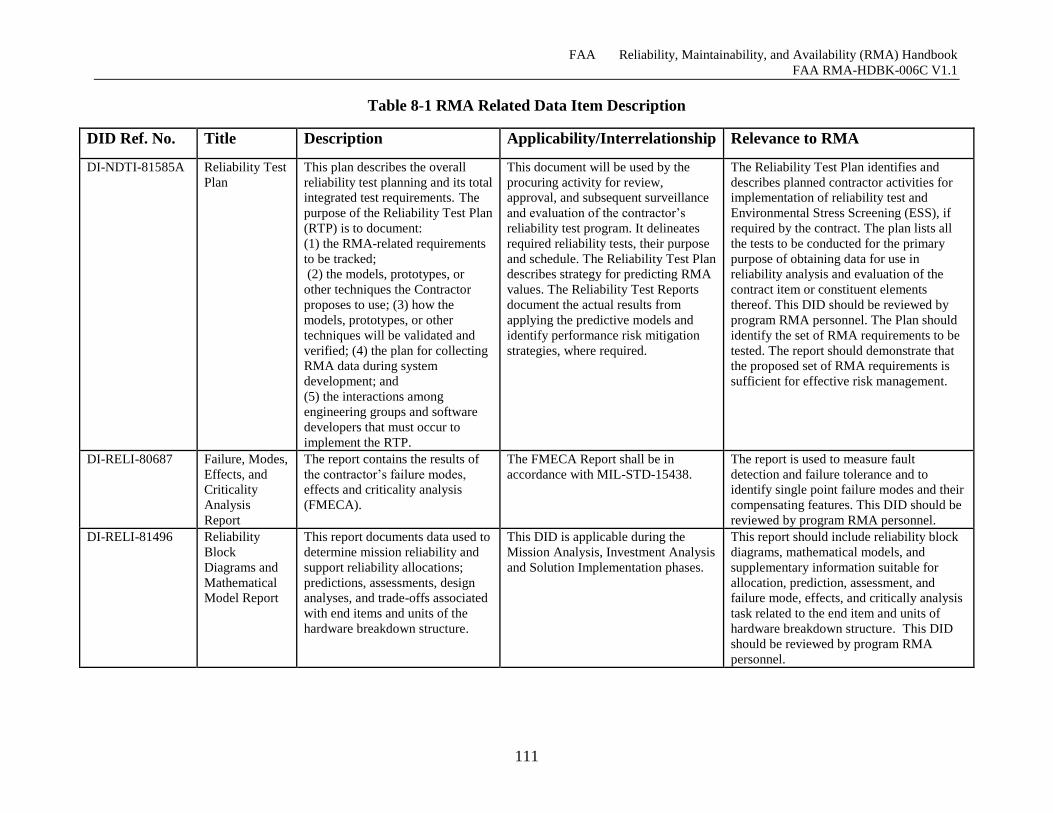
FAA Reliability, Maintainability, and Availability (RMA) Handbook
FAA RMA-HDBK-006C V1.1
111
Table 8-1 RMA Related Data Item Description
DID Ref. No. Title Description Applicability/Interrelationship Relevance to RMA
DI-NDTI-81585A Reliability Test
Plan This plan describes the overall
reliability test planning and its total
integrated test requirements. The
purpose of the Reliability Test Plan
(RTP) is to document:
(1) the RMA-related requirements
to be tracked;
(2) the models, prototypes, or
other techniques the Contractor
proposes to use; (3) how the
models, prototypes, or other
techniques will be validated and
verified; (4) the plan for collecting
RMA data during system
development; and
(5) the interactions among
engineering groups and software
developers that must occur to
implement the RTP.
This document will be used by the
procuring activity for review,
approval, and subsequent surveillance
and evaluation of the contractor’s
reliability test program. It delineates
required reliability tests, their purpose
and schedule. The Reliability Test Plan
describes strategy for predicting RMA
values. The Reliability Test Reports
document the actual results from
applying the predictive models and
identify performance risk mitigation
strategies, where required.
The Reliability Test Plan identifies and
describes planned contractor activities for
implementation of reliability test and
Environmental Stress Screening (ESS), if
required by the contract. The plan lists all
the tests to be conducted for the primary
purpose of obtaining data for use in
reliability analysis and evaluation of the
contract item or constituent elements
thereof. This DID should be reviewed by
program RMA personnel. The Plan should
identify the set of RMA requirements to be
tested. The report should demonstrate that
the proposed set of RMA requirements is
sufficient for effective risk management.
DI-RELI-80687 Failure, Modes,
Effects, and
Criticality
Analysis
Report
The report contains the results of
the contractor’s failure modes,
effects and criticality analysis
(FMECA).
The FMECA Report shall be in
accordance with MIL-STD-15438. The report is used to measure fault
detection and failure tolerance and to
identify single point failure modes and their
compensating features. This DID should be
reviewed by program RMA personnel.
DI-RELI-81496 Reliability
Block
Diagrams and
Mathematical
Model Report
This report documents data used to
determine mission reliability and
support reliability allocations;
predictions, assessments, design
analyses, and trade-offs associated
with end items and units of the
hardware breakdown structure.
This DID is applicable during the
Mission Analysis, Investment Analysis
and Solution Implementation phases.
This report should include reliability block
diagrams, mathematical models, and
supplementary information suitable for
allocation, prediction, assessment, and
failure mode, effects, and critically analysis
task related to the end item and units of
hardware breakdown structure. This DID
should be reviewed by program RMA
personnel.
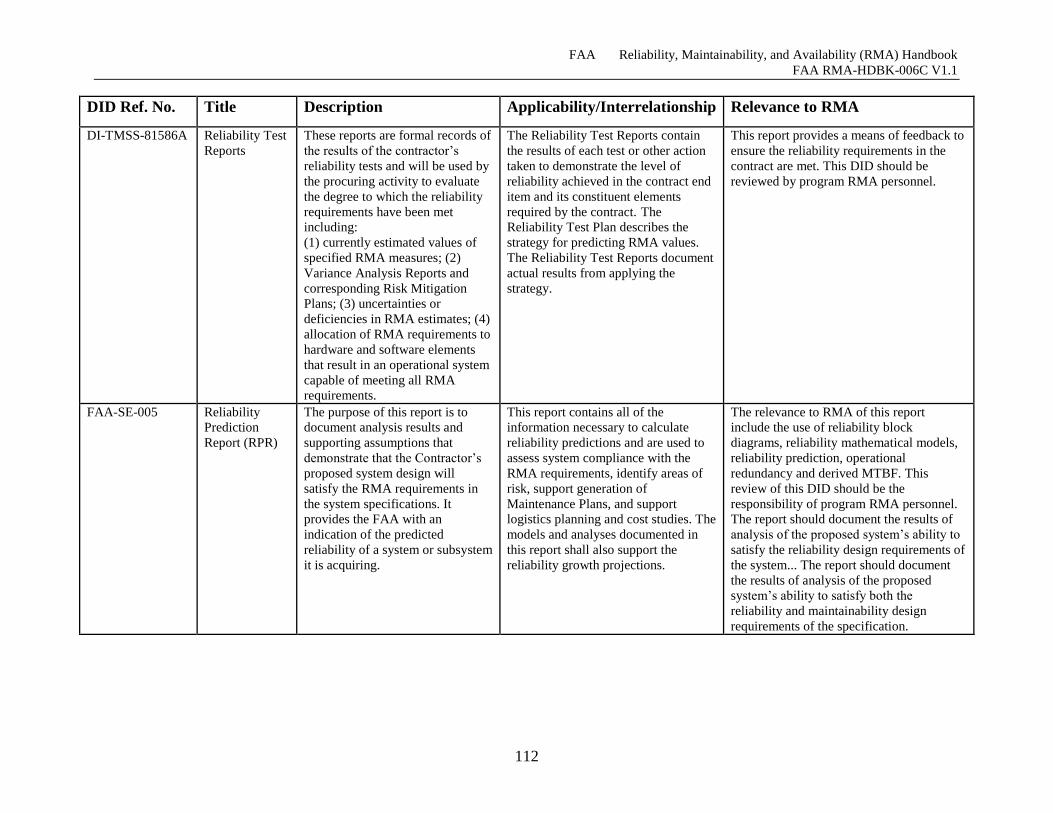
FAA Reliability, Maintainability, and Availability (RMA) Handbook
FAA RMA-HDBK-006C V1.1
112
DID Ref. No. Title Description Applicability/Interrelationship Relevance to RMA
DI-TMSS-81586A Reliability Test
Reports These reports are formal records of
the results of the contractor’s
reliability tests and will be used by
the procuring activity to evaluate
the degree to which the reliability
requirements have been met
including:
(1) currently estimated values of
specified RMA measures; (2)
Variance Analysis Reports and
corresponding Risk Mitigation
Plans; (3) uncertainties or
deficiencies in RMA estimates; (4)
allocation of RMA requirements to
hardware and software elements
that result in an operational system
capable of meeting all RMA
requirements.
The Reliability Test Reports contain
the results of each test or other action
taken to demonstrate the level of
reliability achieved in the contract end
item and its constituent elements
required by the contract. The
Reliability Test Plan describes the
strategy for predicting RMA values.
The Reliability Test Reports document
actual results from applying the
strategy.
This report provides a means of feedback to
ensure the reliability requirements in the
contract are met. This DID should be
reviewed by program RMA personnel.
FAA-SE-005 Reliability
Prediction
Report (RPR)
The purpose of this report is to document analysis results and
supporting assumptions that
demonstrate that the Contractor’s
proposed system design will
satisfy the RMA requirements in
the system specifications. It
provides the FAA with an
indication of the predicted
reliability of a system or subsystem
it is acquiring.
This report contains all of the
information necessary to calculate
reliability predictions and are used to
assess system compliance with the
RMA requirements, identify areas of
risk, support generation of
Maintenance Plans, and support
logistics planning and cost studies. The
models and analyses documented in
this report shall also support the
reliability growth projections.
The relevance to RMA of this report
include the use of reliability block
diagrams, reliability mathematical models,
reliability prediction, operational
redundancy and derived MTBF. This
review of this DID should be the
responsibility of program RMA personnel.
The report should document the results of
analysis of the proposed system’s ability to
satisfy the reliability design requirements of
the system... The report should document
the results of analysis of the proposed
system’s ability to satisfy both the
reliability and maintainability design
requirements of the specification.
FAA Reliability, Maintainability, and Availability (RMA) Handbook
FAA RMA-HDBK-006C V1.1
113
These reports must be generated according to a delivery schedule that is part of the contract. The
timing and frequency of these reports should be negotiated to match the progress of the
development of the fault-tolerant design. The fact that these CDRL items are contract
deliverables, upon which contractual performance is measured, limits their usefulness.
8.2.2.3 Risk Reduction Activities The SOW must include adequate levels of contractor support for measurement and tracking of
critical fault tolerance design parameters and risk reduction demonstrations. These activities are
further described in Section 8.4.3.
8.2.2.4 Reliability Modeling Reliability modeling requirements imposed on the contractor should be limited to simple
combinatorial availability models that demonstrate compliance with the inherent availability
requirement. Complex models intended to predict the reliability of undeveloped software and the
effectiveness of fault tolerance mechanisms are highly sensitive to unsubstantiated assumptions,
tend to waste program resources, and generate a false sense of complacency.
8.2.2.5 Performance Modeling In contrast to reliability modeling, performance modeling can be a valuable tool for monitoring
the progress of the design. The success of the design of the fault tolerance mechanisms is highly
dependent on the response times for internal health and error messages. The operation of the
fault tolerance mechanisms in turn can generate a significant processing and communications
overhead.
It is important that the Statement of Work include the requirement to continually maintain and
update workload predictions, software processing path lengths, and processor response time and
capacity predictions. Although performance experts generally assume lead on performance
modeling requirements, these requirements should be reviewed to ensure that they satisfy the
RMA/fault-tolerant needs.
8.2.2.6 Monitor and Control Design Requirement The specification of the Monitor and Control requirements is a particularly difficult task, since
the overall system design is either unknown at the time the specification is being prepared, or, in
the case of a design competition, there are two or more different designs. In the case of
competing designs, the specification must not include detail that could be used to transfer design
data between offerors. The result is that the SSD requirements for the design of the M&C
position are likely to be too general to be very effective in giving the Government the necessary
leverage to ensure an effective user interface for the monitoring and control of the system.
The unavoidable ambiguity of the requirements is likely to lead to disagreements between the
contractor and the Government over the compliance of the M&C design unless the need to
jointly evolve the M&C design after contract award is anticipated and incorporated into the
SOW.
(An alternative way of dealing with this dilemma is presented in Section 8.2.3.2, requiring the
offerors to present a detailed design in their proposals and incorporate the winner’s design into
the contractual requirements.)
FAA Reliability, Maintainability, and Availability (RMA) Handbook
FAA RMA-HDBK-006C V1.1
114
8.2.2.7 Fault Avoidance Strategies The Government may want to mandate that the contractor employ procedures designed to
uncover fault tolerance design defects such as fault tree analysis or failure modes and effects
analysis. Caution should be used in generally mandating these techniques for software
developments, as they are more generally applied to weapons systems or nuclear power plants
where cause and effect are more obvious than in a decision support system. Recent advances in
software development techniques are, however making these techniques more feasible for
application to critical systems, see for example Rebecca Menes and Herb Hecht, “Safety and
Certification of UAVs”, SAE Aerotech Symposium, 2007.
It is assumed that more general fault avoidance strategies such as those used to promote software
quality will be specified by software engineering specialists independent of the RMA/Fault
Tolerance requirements.
8.2.2.8 Reliability Growth Planning for an aggressive reliability growth program is an essential part of the development and
testing of software-intensive systems used in critical applications. As discussed in Section 5, it is
no longer practical to attempt a legalistic approach to enforce contractual compliance with the
reliability requirements for high reliability automation systems. The test time required to obtain a
statistically valid sample on which to base an accept/reject decision would be prohibitive. The
inherent reliability of an automation system architecture represents potential maximum reliability
if the software is perfect. The achieved reliability of an automation system is limited by
undiscovered latent software defects causing system failures. The objective of the reliability
growth program is to expose and correct latent software defects so that the achieved reliability
approaches the inherent reliability.
The SSD contains separate MTBF values for the first site and the last site that can be used as
metrics representing two points on the reliability growth curve. These MTBF values are
calculated by dividing the test time by the number of failures. Because a failure review board
will determine which failures are considered relevant and also expunge failures that have been
fixed or that do not reoccur during a specified interval, there is a major subjective component in
this measure. The MTBF obtained in this manner should not be viewed as a statistically valid
estimate of the true system MTBF. If the contractor fixes the cause of each failure soon after it
occurs, the MTBF could be infinite because there are no open trouble reports – even if the
system is experiencing a failure every day. The MTBF calculated in this manner should be
viewed as metrics that measure a contractor’s responsiveness in fixing problems in a timely
manner. The MTBF requirements are thus an important component in a successful reliability
growth program.
The SOW needs to specify the contractor effort required to implement the reliability growth
program. The SSD needs to include requirements for the additional test tools, simulators, data
recording capability, and data reduction and analysis capability that will be required to support
the reliability growth program. Software Reliability Planning is explained in detail in Appendix
F.
There is a plethora of tools that can be used in at the various Engineering Life-cycle phases for
Software Reliability. Authoritative sources on this subject include DOT/FAA/AR-06/35
“Software Development Tools for Safety-Critical, Real-Time Systems Handbook” [25] and
DOT/FAA/AR-06/36 “Assessment of Software Development Tools for Safety-Critical, Real-
FAA Reliability, Maintainability, and Availability (RMA) Handbook
FAA RMA-HDBK-006C V1.1
115
Time Systems. [21] Specific GOTS tools include the AMSAA Reliability Growth technology
and DO-278 standard for Software Integrity Assurance for CNS/ATM Systems [40]. [10][16]
8.2.2.9 Statement of Work Checklist Provide for RMA and Fault Tolerance TIMs. Define CDRL Items and DIDs to provide the documentation needed to monitor the
development of the fault-tolerant design and the system’s RMA characteristics. Provide for Risk Reduction Demonstrations of critical elements of the fault-tolerant design. Limit required contractor RMA modeling effort to basic one-time combinatorial models of
inherent reliability/availability of the system architecture. Incorporate requirements for continuing performance modeling to track the processing
overhead and response times associated with the operation of the fault tolerance mechanisms,
M&C position, and data recording capability. Provide for contractor effort to evolve the M&C design in response to FAA design reviews. Provide for contractor effort to use analytical tools to discover design defects during the
development. Provide for contractor support for an aggressive reliability growth program.
8.2.3 Information for Proposal Preparation
The IFPP describes material that the Government expects to be included in the offeror’s
proposal. The following information should be provided to assist in the technical evaluation of
the fault tolerance and RMA sections of the proposal.
8.2.3.1 Inherent Availability Model A simple inherent availability model should be included to demonstrate that the proposed
architecture is compliant with the NAS-Level availability requirement. The model’s input
parameters include the element MTBF and MTTR values and the amount of redundancy
provided. The offeror should substantiate the MTBF and MTTR values used as model inputs,
preferably with field data for COTS products, or with reliability and maintainability predictions
for the individual hardware elements.
8.2.3.2 Proposed M&C Design Description and Specifications As discussed in Section 8.2.2.6, it will be difficult or impossible for the Government to
incorporate an unambiguous specification for the M&C position into the SSD. This is likely to
lead to disagreements between the contractor and the Government concerning what is considered
to be compliant with the requirements.
There are two potential ways of dealing with this. One is to request that offerors propose an
M&C design that is specifically tailored to the needs of their proposed system. The M&C
designs would be evaluated as part of the proposal technical evaluation. The winning
contractor’s proposed M&C design would then be incorporated into the contract and made
contractually binding.
Traditionally, the FAA has not used this approach, although it is commonly used in the
Department of Defense. The approach satisfies two important objectives. It facilitates the
specification of design-dependent aspects of the system and it encourages contractor innovation.
FAA Reliability, Maintainability, and Availability (RMA) Handbook
FAA RMA-HDBK-006C V1.1
116
The other is to attempt to defer specification of the M&C function until after contract award,
have the contractor propose an M&C design, review the approach and negotiate a change to the
contract to incorporate the approved approach.
The selection of either approach should be explored with the FAA Contracting Officer.
8.2.3.3 Fault Tolerant Design Description The offeror’s proposal should include a complete description of the proposed design approach
for redundancy management and automatic fault detection and recovery. The design should be
described qualitatively. In addition, the offeror should provide quantitative substantiation that the
proposed design can comply with the recovery time requirements.
The offeror should also describe the strategy and process for incorporating fault tolerance
mechanisms in the application software to handle unwanted, unanticipated, or erroneous inputs
and responses.
8.3 Proposal Evaluation The following topics represent the key factors in evaluating each offeror’s approach to
developing a system that will meet the operational needs for reliability and availability.
8.3.1 Reliability, Maintainability and Availability Modeling and Assessment
The evaluation of the offeror’s inherent availability model is simple and straightforward. All that
is required is to confirm that the model accurately represents the architecture and that the
mathematical formulas are correct. The substantiation of the offeror’s MTBF and MTTR values
used as inputs to the model should be also reviewed and evaluated. Appendix B provides tables
and charts that can be used to check each offeror’s RMA model.
8.3.2 Fault-Tolerant Design Evaluation
The offeror’s proposed design for automatic fault detection and recovery/redundancy
management should be evaluated for its completeness and consistency. A critical factor in the
evaluation is the substantiation of the design’s compliance with the recovery time requirements.
There are key two aspects of the fault-tolerant design. The first is the design of the infrastructure
component that contains the protocols for health monitoring, fault detection, error recovery, and
redundancy management.
Equally important is the offeror’s strategy for incorporating fault tolerance into the application
software. Unless fault tolerance is embedded into the application software, the ability of the
fault-tolerant infrastructure to effectively mask software faults will be severely limited. The
ability to handle unwanted, unanticipated, or erroneous inputs and responses must be
incorporated during the development of the application software.
8.3.3 Performance Modeling and Assessment
An offeror should present a complete model of the predicted system loads, capacity, and
response times. Government experts in performance modeling should evaluate these models.
Fault tolerance evaluators should review the models in the following areas:
FAA Reliability, Maintainability, and Availability (RMA) Handbook
FAA RMA-HDBK-006C V1.1
117
Latency of fault tolerance protocols: The ability to respond within the allocated response
time is critical to the success of the fault tolerance design. It should be noted that, at the
proposal stage, the level of the design may not be adequate to address this issue.
System Monitoring Overhead and Response Times: The offeror should provide
predictions of the additional processor loading generated to support both the system
monitoring performed by the M&C function as well as by the fault tolerance heartbeat
protocols and error reporting functions. Both steady-state loads and peak loads generated
during fault conditions should be considered.
Relation to Overall System Capacity and Response Times: The system should be sized
with sufficient reserve capacity to accommodate peaks in the external workload without
causing slowdowns in the processing of fault tolerance protocols. Adequate memory
should be provided to avoid paging delays that are not included in the model predictions.
8.4 Contractor Design Monitoring The following topics represent the key design monitoring activities applied to a system that will
ensure that it meets the operational needs for reliability and availability.
8.4.1 Formal Design Reviews
Formal design reviews are a contractual requirement. Although these reviews are often too large
and formal to include a meaningful dialog with the contractor, they do present an opportunity to
escalate technical issues to management’s attention.
8.4.2 Technical Interchange Meetings
The contractor’s design progress should be reviewed in monthly TIMs. In addition to describing
the design, the TIM should address the key timing parameters governing the operation of the
fault tolerance protocols, the values allocated to the parameters, and the results of model
predictions and or measurements made to substantiate the allocations.
8.4.3 Risk Management
The objective of the fault tolerance risk management activities is to expose flaws in the design as
early as possible, so that they can be corrected “off the critical path” without affecting the overall
program cost and schedule. Typically, major acquisition programs place major emphasis on
formal design reviews such as the specification reviews, the system design reviews, preliminary
and critical design reviews. After the CDR has been successfully completed, lists of Computer
Program Configuration Items (CPCIs) are released for coding, beginning the implementation
phase of the contract. After CDR, there are no additional formal technical software reviews until
the end of implementation phase when the Functional and Physical Configuration Audits (FCA
and PCA) and formal acceptance tests are conducted.
Separate fault tolerance risk management activities should be established for:
Fault tolerant infrastructure
Error handling in software applications
Performance monitoring
FAA Reliability, Maintainability, and Availability (RMA) Handbook
FAA RMA-HDBK-006C V1.1
118
The fault-tolerant infrastructure will generally be developed by individuals whose primary
objective is to deliver a working infrastructure. Risk management activities associated with the
infrastructure development are directed toward uncovering logic flaws and timing/performance
problems.
In contrast to hardware designers and the overall system architect, application developers are not
primarily concerned with fault tolerance. Their main challenge is to develop the functionality
required of the application. Under schedule pressure to demonstrate the required functionality,
building in the fault tolerance capabilities that need to be embedded into the application software
is often overlooked or indefinitely postponed during the development of the application. Once
the development has been largely completed, it can be extremely difficult to incorporate fault
tolerance into the applications after the fact. Risk management for software application fault
tolerance consists of establishing standards for applications developers and ensuring that the
standards are followed.
Risk management of performance is typically focused on the operational functionality of the
system. Special emphasis needs to be placed on the performance monitoring risk management
activity to make sure that failure, failure recovery operations, system initialization/re-
initialization, and switchover characteristics are properly modeled.
8.4.3.1 Fault Tolerance Infrastructure Risk Management The development of a fault-tolerant infrastructure primarily entails constructing mechanisms that
monitor the health of the system hardware and software as well as provide the logic to switch,
when necessary, to redundant elements.
The primary design driver for the fault tolerance infrastructure is the required recovery time.
Timing parameters must be established to achieve a bounded recovery time, and the system
performance must accommodate the overhead associated with the fault tolerance monitoring and
deliver responses within established time boundaries. The timing budgets and parameters for the
fault-tolerant design are derived from this requirement. The fault-tolerant timing parameters, in
turn, determine the steady state processing overhead imposed by the fault tolerance
infrastructure.
The risk categories associated with the fault tolerance infrastructure can be generally categorized
as follows:
System Performance Risk
System Resource Usage
System Failure Coverage
If the system is to achieve a bounded recovery time, it is necessary to employ synchronous
protocols. The use of these protocols, in turn, impose strict performance requirements on such
things as clock synchronization accuracy, end-to-end communications delays for critical fault
tolerance messages, and event processing times.
The first priority in managing the fault tolerance infrastructure risks is to define the timing
parameters and budgets required to meet the recovery time specification. Once this has been
accomplished, performance modeling techniques can be used to make initial predictions and
measurements of the performance of the developed code can be compared with the predictions to
identify potential problem areas.
FAA Reliability, Maintainability, and Availability (RMA) Handbook
FAA RMA-HDBK-006C V1.1
119
The risk management program should address such factors as the overall load imposed on the
system by the fault tolerance infrastructure and the prediction and measurement of clock
synchronization accuracy, end-to-end communication delays,
Although it is virtually impossible to predict the system failure coverage in advance, or verify it
after-the-fact with enough accuracy to be useful, a series of risk reduction demonstrations using
Government generated scenarios that attempt to “break” the fault-tolerant mechanisms has
proven to be effective in exposing latent design defects in the infrastructure software. Using this
approach, it is often possible that the defects can be corrected before deployment.
8.4.3.1.1 Application Fault Tolerance Risk Management
Monitoring the embedded fault tolerance capabilities in application software is particularly
challenging because functionality, not fault tolerance, is the primary focus of the application
software developers. Risk management in this area consists of:
Establishing fault tolerance design guidelines for application developers, and Monitoring the
compliance of the application software with the design guidelines.
The overall fault tolerance infrastructure is primarily concerned with redundancy management –
that is, with monitoring the “health” of hardware and software modules and performing whatever
reconfigurations and switchovers are needed to mask failures of these modules. In essence, the
fault tolerance infrastructure software deals with the interaction of “black boxes.”
In contrast with this basic infrastructure, application fault tolerance is intimately connected with
details of the functions that the application performs and with how it interfaces with other
applications. Consider a possible scenario: one application module asks another to amend a
flight plan, but the receiving application has no record of that flight plan. Among the possible
responses, the receiving application could simply reject the amendment, it could request that the
entire flight plan be resubmitted, or it could send an error message to the controller who (it
assumes) submitted the request.
What should not be allowed to happen in the above scenario would be for the error condition to
propagate up to the interface between the application module and the fault tolerance
infrastructure. At that level, the only way to handle the problem would be to switch to a standby
application module – and that module would just encounter the same problem. Simply stated, the
fault tolerance infrastructure is not equipped to handle application-specific error conditions. This
high-level capability should only handle catastrophic software failures such as a module crash or
other non-recoverable error.
In the development of fault-tolerant application software it is important to establish definitive
fault tolerance programming standards for the application software developers. These standards
should specify different classes of faults and the manner in which they should be handled.
Programmers should be required to handle errors at the lowest possible level and prohibited from
simply propagating the error out of their immediate domain.
Since an application programmer’s primary focus is on delivering the required functionality for
their application, it will be a continuing battle to monitor their compliance with the fault
tolerance programming standards. Automated tools are available that can search the source code
FAA Reliability, Maintainability, and Availability (RMA) Handbook
FAA RMA-HDBK-006C V1.1
120
exception handling and identify questionable exception handling practices. Failure Modes and
Effects Analysis (FMEA) techniques can be used to review the error handling associated with
transactions between software application modules. Traditional FMEA and Failure Mode,
Effects and Criticality Analysis (FMECA) techniques or System Safety practices defined in
MIL-STD-882D are oriented toward military weapons systems and are focused toward failures
that directly cause injury or loss of life.
What is needed for application fault tolerance is a systematic approach to identify potential
erroneous responses in the communications between software applications and verification that
appropriate responses to the error conditions are incorporated into the software.
The important point to recognize is that the fault tolerance infrastructure alone cannot ensure a
successful fault-tolerant system. Without “grassroots” fault tolerance embedded throughout the
application software, the redundancy management fault tolerance infrastructure will be
ineffective in ensuring a high reliability system.
Fault tolerance must be embedded in the applications from the ground up, as the software is
developed. It can be extremely difficult to attempt to incorporate it after the fact.
The job of the application fault tolerance risk management activity is to ensure that the
programmers have fault tolerance programming standards at the start of software development
and to continuously track their adherence to the standards throughout the implementation phase.
8.4.3.2 Performance Monitoring Risk Management As noted in 8.2.1.1, system performance and response times are closely coupled to reliability
issues. The requirement to have rapid, consistent automatic fault detection and recovery times
imposes rigid and inflexible response time requirements on the internal messages used to
monitor the system’s health and initiate automatic recovery actions. If the allocated response
times are exceeded, false alarms may be generated and inconsistent and incomplete recovery
actions will result.
Although it is the contractor’s responsibility to allocate recovery time requirements to lower
level system design parameters, attempting to design to unrealistic parameters can significantly
increase program risk. Ultimately, it is likely that the recovery time requirement will need to be
reduced to an achievable value. It is preferable, however, to avoid the unnecessary cost and
schedule expenses that result from attempting to meet an unrealistic requirement. The
Government should attempt to write realistic requirements. It is also necessary to watch the
development closely through a contractor-developed, but Government-monitored, risk
management effort. Establishing performance parameters tailored to the performance dependent
RMA characteristics and formally monitoring those parameters through periodic risk
management activities is an effective means of mitigating the associated risks.
8.4.3.3 Software Reliability Growth Plan Monitoring In cases where effort is specified for the contractor as a part of Software Reliability Growth
Planning as described in Appendix F monitoring by the government may be required to verify
that the contractor is meeting the requirements of the plan and the plan is being implemented and
followed. Activities may be required such as audits, contractor performance reporting as well as
monitoring software assurance activities and the review of deliverables. The level-of-effort
required by the contractor and the government is dependent upon the effort identified in
Appendix G.2.
FAA Reliability, Maintainability, and Availability (RMA) Handbook
FAA RMA-HDBK-006C V1.1
121
8.5 Design Validation and Acceptance Testing As discussed previously, it is not possible to verify compliance with stringent reliability
requirements within practical cost and schedule constraints. There is, however, much that can be
done to build confidence in the design and operation of the fault tolerance mechanisms and in the
overall stability of the system and its readiness for deployment.
8.5.1 Fault Tolerance Diagnostic Testing
Despite an aggressive risk management program, many performance and stability problems do
not materialize until large scale testing begins. The SAR and the DR&A capabilities provide an
opportunity to leverage the data recorded during system testing to observe the operation of the
fault tolerance protocols and diagnose problems and abnormalities experienced during their
operation.
For system testing to be effective, the SAR and DR&A capabilities should be available when
testing begins. Without these capabilities it is difficult to diagnose and correct internal software
problems.
8.5.2 Functional Testing
Much of the test time at the WJHTC is devoted to verifying compliance with each of the
functional requirements. This testing should also include verification of compliance with the
functional requirements for the systems operations functions including:
Monitor and Control (M&C)
System Analysis and Recording (SAR)
Data Reduction and Analysis (DR&A)
8.5.3 Reliability Growth Testing
As discussed in Appendix C, a formal reliability demonstration test in which the system is either
accepted or rejected based on the test results is not feasible. The test time required to obtain a
statistically valid sample is prohibitive, and the large number of software failures encountered in
any major software development program would virtually ensure failure to demonstrate
compliance with the requirements. Establishing perfect “pass-fail” criteria for a major system
acquisition is not a viable alternative, rather the program manager should establish an acceptable
level of failure rate as an acceptance criteria. Attaining and maintaining this level is illustrated in
Figure F-5.
Reliability growth testing is an on-going process of testing, and correcting failures. Reliability
growth was initially developed to discover and correct hardware design defects. Statistical
methods were developed to predict the system MTBF at any point in time and to estimate the
additional test time required to achieve a given MTBF goal.
Reliability growth testing applied to automation systems is a process of exposing and correcting
latent software defects. The hundreds of software defects exposed during system testing, coupled
with the stringent reliability requirements for these systems, preclude the use of statistical
methods to accurately predict the test time to reach a given MTBF prior to system deployment.
There is no statistically valid way to verify compliance with reliability requirements at the
FAA Reliability, Maintainability, and Availability (RMA) Handbook
FAA RMA-HDBK-006C V1.1
122
WJHTC prior to field deployment. There is a simple reason for this: it is not possible to obtain
enough operating hours at the WJHTC to reduce the number of latent defects to the level needed
to meet the reliability requirements.
The inescapable conclusion is that it will be necessary to field systems that fall short of meeting
the reliability requirements. The large number of additional operating hours accumulated by
multiple system installations will increase the rate that software errors are found and corrected
and the growth of the system MTBF.
To be successful, the reliability growth program must address two issues. First, the contractor
must be aggressive at promptly correcting software defects. The contractor must be given a
powerful incentive to keep the best people on the job through its completion, instead of moving
them to work on new opportunities. This can be accomplished by a process called “expunging.”
The system MTBF was computed by dividing the operating hours by the number of failures.
However if the contractor could demonstrate that the cause of the failure had been corrected then
the failure was “expunged” from the list of failures. If a failure cannot be repeated within 30
days, it is also expunged from the database.
Thus, if all PTRs are fixed immediately, the computed MTBF would be infinity even if the
system were failing on daily basis. This measure is statistically meaningless as a true indicator of
the system MTBF. It is, however, a useful metric for assessing the responsiveness of the
contractor in fixing the backlog of accumulated PTRs. Since the Government representatives
decide when to expunge errors from the database, they have considerable leverage over the
contractor by controlling the value of the MTBF reported to senior program management
officials. There may be other or better metrics that could be used to measure the contractor’s
responsiveness in fixing PTRs. The important thing is that there must be a process in place to
measure the success of the contractor’s program to support reliability growth.
The second issue that must be addressed during the reliability growth program is the
acceptability of the system to field personnel. In all probability, the system will be deployed to
field sites before it has met the reliability requirements. Government field personnel should be
involved in the reliability growth testing at the WJHTC and concur in the decision concerning
when the system is sufficiently stable to warrant sending it to the field.
As discussed in Appendix C, it is not possible to verify compliance with stringent reliability
requirements within practical cost and schedule constraints. There is, however, much that can be
done to build confidence in the design and operation of the fault tolerance mechanisms and in the
overall stability of the system and its readiness for deployment. The way to accomplish this is to
provide the test tools, personnel, and test time to pursue an aggressive reliability growth
program.
FAA Reliability, Maintainability, and Availability (RMA) Handbook
FAA RMA-HDBK-006C V1.1
123
SERVICE THREAD MANAGEMENT
The NAS-RD RMA requirements have been designed so that they should be largely independent
of changes in the NAS Architecture or the NAS-RD-20XX functional requirements. The concept
of associating RMA requirements with severity levels and severity levels with NAS functions
remains constant even as the NAS-RD evolves.
Table 7-2 defines the mapping between the approved set of NAPRS services and to the set of
service threads. The complete set of service threads consists of most, but not all, of the NAPRS
services, NAPRS facilities that have been converted to service threads, and newly created service
threads that are not defined in NAPRS services.
When existing service threads are substantially changed or new service threads are added, SMEs
should be consulted to ensure that service thread severity is appropriately categorized and that
other impacts to the NAS are captured.
9.1 Revising Service Thread Requirements One of the advantages of the service thread- based approach is that the service threads can
remain almost constant as the NAS Architecture evolves. Many, if not most, of the changes to
the NAS Architecture involve replacement of a facility representing a block in the reliability
block diagram for the thread. Thus, the basic thread does not need to change, only the name of a
block in the thread. As the NAS evolves, the service thread diagrams should evolve with it. It is
the responsibility of the NAS Requirements Management Group to maintain these service thread
diagrams. Because the service threads need to address requirements and specification issues long
before prototyping and deployment, systems approved for acquisition or major prototype systems
may need to be included.
All changes from the set of service threads set forth for the approved services in NAPRS should
be coordinated with ATO Technical Operations.
9.2 Adding a New Service Thread Service threads may need to be added in the future to accommodate new NAS capabilities. With
the structure provided by this Handbook, new service threads will not necessarily have to rely on
the NAS-Level RMA severity definitions. Rather, it will be possible to move straight to defining
the SLTSC for the new service thread and its place in the NAS. Then, all RMA-related
requirements should follow more easily.
A major objective of this Handbook is to couple the RMA requirements to real-world NAS
services. This linkage is achieved within the STLSC matrices which associate RMA
requirements service threads which are derived from real-world NAS services. Since there will
be a need to create services in addition to those defined in NAPRS, it will be important to
continue to distinguish between the official operational FAA services and services that have been
created to support requirements development and acquisition planning.
All deviations from the set of service threads set forth for the approved services in NAPRS
should be coordinated with ATO Technical Operations. With this coordination, as new services
are deployed, there can be an orderly transition between the hypothetical service threads and the
NAPRS services.
FAA Reliability, Maintainability, and Availability (RMA) Handbook
FAA RMA-HDBK-006C V1.1
124
9.3 FSEP and NAPRS
FAA Order 6000.5, Facility, Service, and Equipment Profile (FSEP). The NAS is a complex
collection of facilities, systems, procedures, aircraft, and people. The physical components of the
NAS, excluding people, which provide for safe separation and control over aircraft are referred
to as the NAS Infrastructure. The FSEP provides an accurate inventory of the NAS Operational
Infrastructure and the NAPRS pseudo-services.
Current information on the FSEP and appropriate Technical Operations points of contact can be
found on the FSEP website at: FSEP website link
FAA Order 6040.15, National Airspace Performance Reporting System (NAPRS) serves as a
timely and accurate performance information reporting system for use in determining and
evaluating the operating condition of NAS facilities/services.
Current information on reportable NAPRS facilities and services and appropriate Technical
Operations points of contact can be found on the NAPRS website at: NAPRS website link
Note: Not all facilities and services in FSEP are NAPRS reportable.
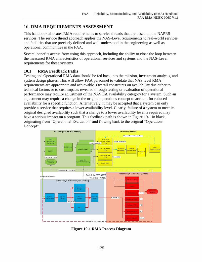
FAA Reliability, Maintainability, and Availability (RMA) Handbook
FAA RMA-HDBK-006C V1.1
125
RMA REQUIREMENTS ASSESSMENT
This handbook allocates RMA requirements to service threads that are based on the NAPRS
services. The service thread approach applies the NAS-Level requirements to real-world services
and facilities that are precisely defined and well-understood in the engineering as well as
operational communities in the FAA.
Several benefits accrue from using this approach, including the ability to close the loop between
the measured RMA characteristics of operational services and systems and the NAS-Level
requirements for these systems.
10.1 RMA Feedback Paths Testing and Operational RMA data should be fed back into the mission, investment analysis, and
system design phases. This will allow FAA personnel to validate that NAS level RMA
requirements are appropriate and achievable. Overall constraints on availability due either to
technical factors or to cost impacts revealed through testing or evaluation of operational
performance may require adjustment of the NAS EA availability category for a system. Such an
adjustment may require a change in the original operations concept to account for reduced
availability for a specific function. Alternatively, it may be accepted that a system can only
provide a service that requires a lower availability level. Clearly, failure of a system to meet its
original designed availability such that a change to a lower availability level is required may
have a serious impact on a program. This feedback path is shown in Figure 10-1 in black,
originating from “Operational Evaluation” and flowing back to the original “Operations
Concept”.
Figure 10-1 RMA Process Diagram
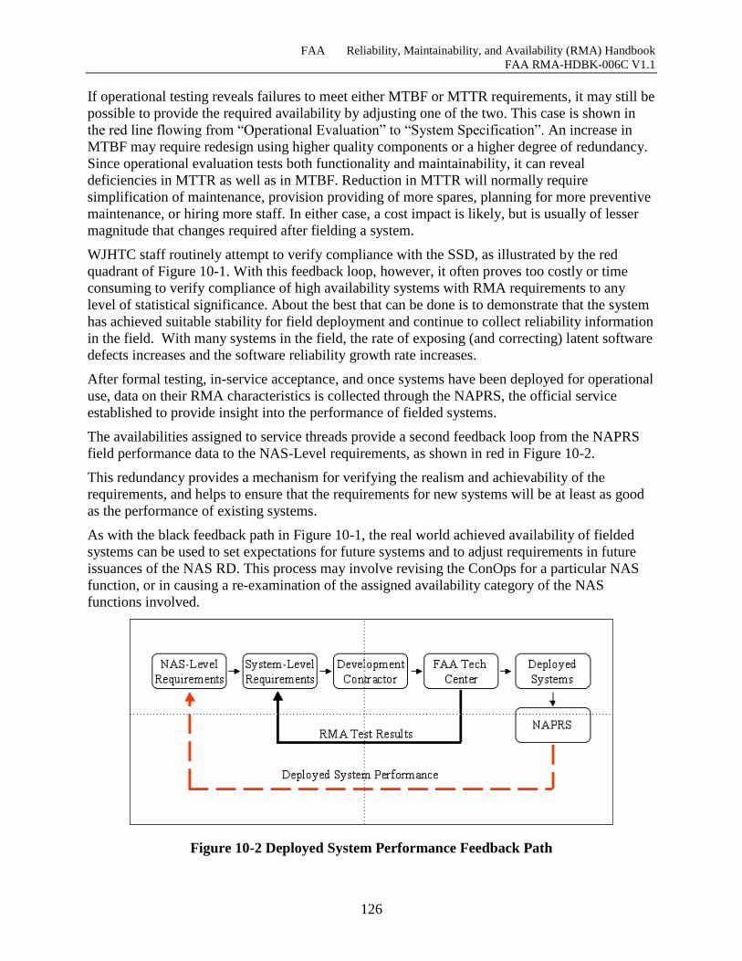
FAA Reliability, Maintainability, and Availability (RMA) Handbook
FAA RMA-HDBK-006C V1.1
126
If operational testing reveals failures to meet either MTBF or MTTR requirements, it may still be
possible to provide the required availability by adjusting one of the two. This case is shown in
the red line flowing from “Operational Evaluation” to “System Specification”. An increase in
MTBF may require redesign using higher quality components or a higher degree of redundancy.
Since operational evaluation tests both functionality and maintainability, it can reveal
deficiencies in MTTR as well as in MTBF. Reduction in MTTR will normally require
simplification of maintenance, provision providing of more spares, planning for more preventive
maintenance, or hiring more staff. In either case, a cost impact is likely, but is usually of lesser
magnitude that changes required after fielding a system.
WJHTC staff routinely attempt to verify compliance with the SSD, as illustrated by the red
quadrant of Figure 10-1. With this feedback loop, however, it often proves too costly or time
consuming to verify compliance of high availability systems with RMA requirements to any
level of statistical significance. About the best that can be done is to demonstrate that the system
has achieved suitable stability for field deployment and continue to collect reliability information
in the field. With many systems in the field, the rate of exposing (and correcting) latent software
defects increases and the software reliability growth rate increases.
After formal testing, in-service acceptance, and once systems have been deployed for operational
use, data on their RMA characteristics is collected through the NAPRS, the official service
established to provide insight into the performance of fielded systems.
The availabilities assigned to service threads provide a second feedback loop from the NAPRS
field performance data to the NAS-Level requirements, as shown in red in Figure 10-2.
This redundancy provides a mechanism for verifying the realism and achievability of the
requirements, and helps to ensure that the requirements for new systems will be at least as good
as the performance of existing systems.
As with the black feedback path in Figure 10-1, the real world achieved availability of fielded
systems can be used to set expectations for future systems and to adjust requirements in future
issuances of the NAS RD. This process may involve revising the ConOps for a particular NAS
function, or in causing a re-examination of the assigned availability category of the NAS
functions involved.
Figure 10-2 Deployed System Performance Feedback Path
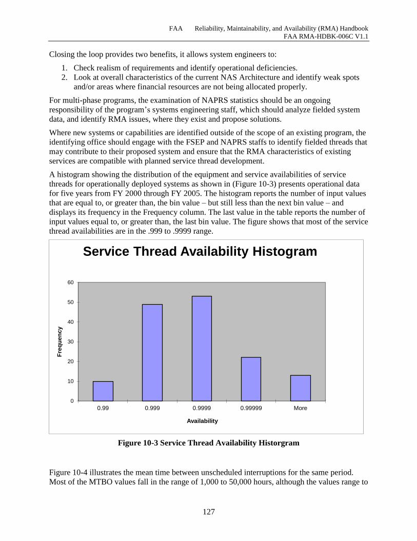
FAA Reliability, Maintainability, and Availability (RMA) Handbook
FAA RMA-HDBK-006C V1.1
127
Closing the loop provides two benefits, it allows system engineers to:
1. Check realism of requirements and identify operational deficiencies.
2. Look at overall characteristics of the current NAS Architecture and identify weak spots
and/or areas where financial resources are not being allocated properly.
For multi-phase programs, the examination of NAPRS statistics should be an ongoing
responsibility of the program’s systems engineering staff, which should analyze fielded system
data, and identify RMA issues, where they exist and propose solutions.
Where new systems or capabilities are identified outside of the scope of an existing program, the
identifying office should engage with the FSEP and NAPRS staffs to identify fielded threads that
may contribute to their proposed system and ensure that the RMA characteristics of existing
services are compatible with planned service thread development.
A histogram showing the distribution of the equipment and service availabilities of service
threads for operationally deployed systems as shown in (Figure 10-3) presents operational data
for five years from FY 2000 through FY 2005. The histogram reports the number of input values
that are equal to, or greater than, the bin value – but still less than the next bin value – and
displays its frequency in the Frequency column. The last value in the table reports the number of
input values equal to, or greater than, the last bin value. The figure shows that most of the service
thread availabilities are in the .999 to .9999 range.
Figure 10-3 Service Thread Availability Historgram
Figure 10-4 illustrates the mean time between unscheduled interruptions for the same period.
Most of the MTBO values fall in the range of 1,000 to 50,000 hours, although the values range to
0
10
20
30
40
50
60
0.99 0.999 0.9999 0.99999 More
Fre
qu
en
cy
Availability
Service Thread Availability Histogram
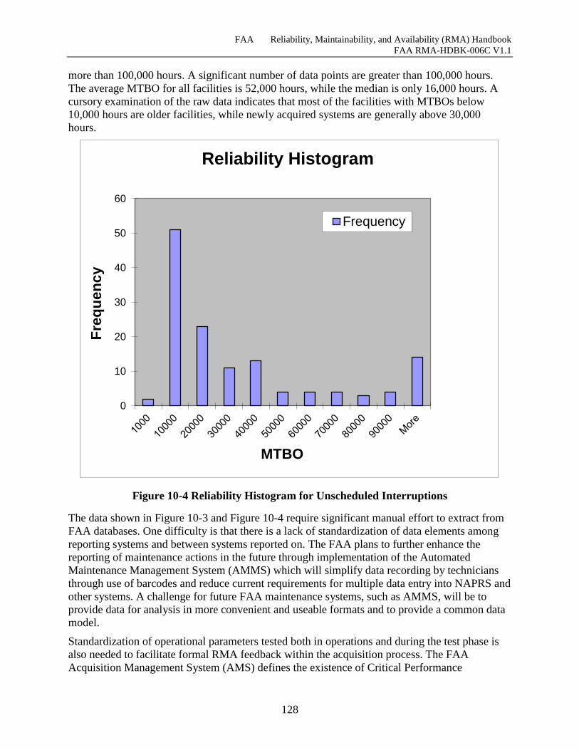
FAA Reliability, Maintainability, and Availability (RMA) Handbook
FAA RMA-HDBK-006C V1.1
128
more than 100,000 hours. A significant number of data points are greater than 100,000 hours.
The average MTBO for all facilities is 52,000 hours, while the median is only 16,000 hours. A
cursory examination of the raw data indicates that most of the facilities with MTBOs below
10,000 hours are older facilities, while newly acquired systems are generally above 30,000
hours.
Figure 10-4 Reliability Histogram for Unscheduled Interruptions
The data shown in Figure 10-3 and Figure 10-4 require significant manual effort to extract from
FAA databases. One difficulty is that there is a lack of standardization of data elements among
reporting systems and between systems reported on. The FAA plans to further enhance the
reporting of maintenance actions in the future through implementation of the Automated
Maintenance Management System (AMMS) which will simplify data recording by technicians
through use of barcodes and reduce current requirements for multiple data entry into NAPRS and
other systems. A challenge for future FAA maintenance systems, such as AMMS, will be to
provide data for analysis in more convenient and useable formats and to provide a common data
model.
Standardization of operational parameters tested both in operations and during the test phase is
also needed to facilitate formal RMA feedback within the acquisition process. The FAA
Acquisition Management System (AMS) defines the existence of Critical Performance
0
10
20
30
40
50
60
Fre
qu
en
cy
MTBO
Reliability Histogram
Frequency
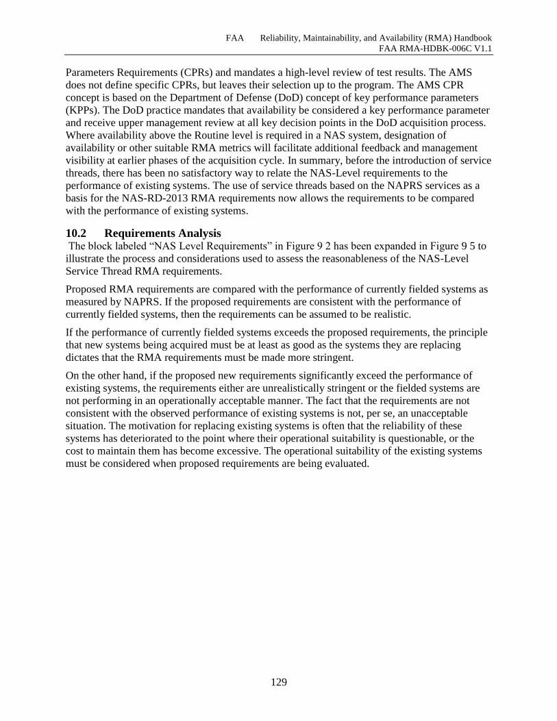
FAA Reliability, Maintainability, and Availability (RMA) Handbook
FAA RMA-HDBK-006C V1.1
129
Parameters Requirements (CPRs) and mandates a high-level review of test results. The AMS
does not define specific CPRs, but leaves their selection up to the program. The AMS CPR
concept is based on the Department of Defense (DoD) concept of key performance parameters
(KPPs). The DoD practice mandates that availability be considered a key performance parameter
and receive upper management review at all key decision points in the DoD acquisition process.
Where availability above the Routine level is required in a NAS system, designation of
availability or other suitable RMA metrics will facilitate additional feedback and management
visibility at earlier phases of the acquisition cycle. In summary, before the introduction of service
threads, there has been no satisfactory way to relate the NAS-Level requirements to the
performance of existing systems. The use of service threads based on the NAPRS services as a
basis for the NAS-RD-2013 RMA requirements now allows the requirements to be compared
with the performance of existing systems.
10.2 Requirements Analysis The block labeled “NAS Level Requirements” in Figure 9 2 has been expanded in Figure 9 5 to
illustrate the process and considerations used to assess the reasonableness of the NAS-Level
Service Thread RMA requirements.
Proposed RMA requirements are compared with the performance of currently fielded systems as
measured by NAPRS. If the proposed requirements are consistent with the performance of
currently fielded systems, then the requirements can be assumed to be realistic.
If the performance of currently fielded systems exceeds the proposed requirements, the principle
that new systems being acquired must be at least as good as the systems they are replacing
dictates that the RMA requirements must be made more stringent.
On the other hand, if the proposed new requirements significantly exceed the performance of
existing systems, the requirements either are unrealistically stringent or the fielded systems are
not performing in an operationally acceptable manner. The fact that the requirements are not
consistent with the observed performance of existing systems is not, per se, an unacceptable
situation. The motivation for replacing existing systems is often that the reliability of these
systems has deteriorated to the point where their operational suitability is questionable, or the
cost to maintain them has become excessive. The operational suitability of the existing systems
must be considered when proposed requirements are being evaluated.
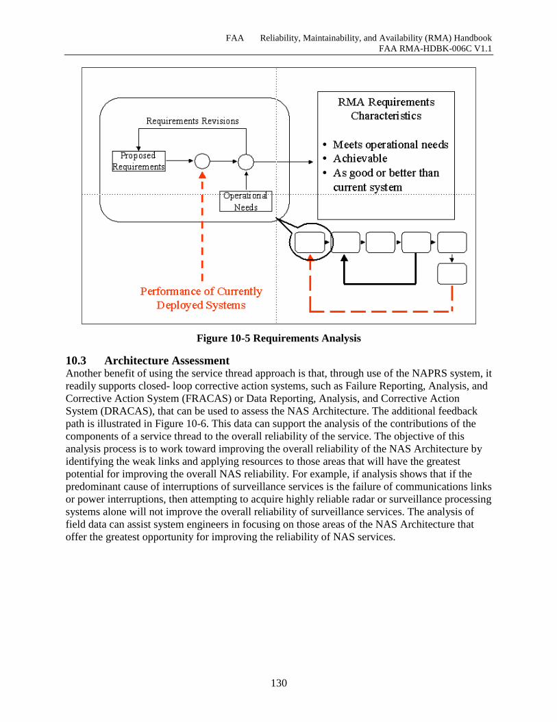
FAA Reliability, Maintainability, and Availability (RMA) Handbook
FAA RMA-HDBK-006C V1.1
130
Figure 10-5 Requirements Analysis
10.3 Architecture Assessment Another benefit of using the service thread approach is that, through use of the NAPRS system, it
readily supports closed- loop corrective action systems, such as Failure Reporting, Analysis, and
Corrective Action System (FRACAS) or Data Reporting, Analysis, and Corrective Action
System (DRACAS), that can be used to assess the NAS Architecture. The additional feedback
path is illustrated in Figure 10-6. This data can support the analysis of the contributions of the
components of a service thread to the overall reliability of the service. The objective of this
analysis process is to work toward improving the overall reliability of the NAS Architecture by
identifying the weak links and applying resources to those areas that will have the greatest
potential for improving the overall NAS reliability. For example, if analysis shows that if the
predominant cause of interruptions of surveillance services is the failure of communications links
or power interruptions, then attempting to acquire highly reliable radar or surveillance processing
systems alone will not improve the overall reliability of surveillance services. The analysis of
field data can assist system engineers in focusing on those areas of the NAS Architecture that
offer the greatest opportunity for improving the reliability of NAS services.
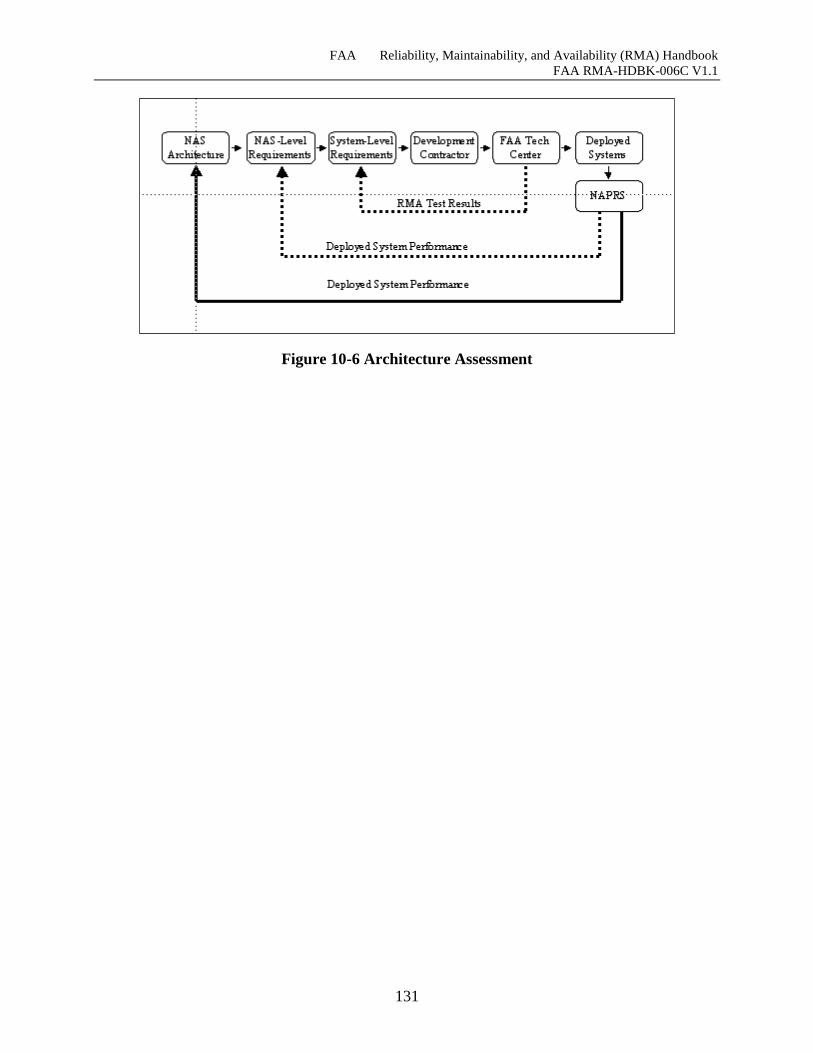
FAA Reliability, Maintainability, and Availability (RMA) Handbook
FAA RMA-HDBK-006C V1.1
131
Figure 10-6 Architecture Assessment
FAA Reliability, Maintainability, and Availability (RMA) Handbook
FAA RMA-HDBK-006C V1.1
132
NOTES
11.1 Updating this Handbook This Handbook is designed to be a living document that will develop and be refined over time,
both through changes in the NAS and the NAS-RD-20XX, and through its use to assist in the
preparation of RMA packages for system acquisitions. While the first process will be driven by
FAA Systems Engineering, the second process will only be possible if the users of the Handbook
comment on its use.
While the Handbook is being used for its intended purpose, the acquisition manager or Business
Unit personnel should keep notes regarding the areas where the Handbook was either helpful or
where it was lacking. These notes and comments about the Handbook should then be provided to
the NAS Systems Engineering Services Office, NAS Requirements Services Division (ANG-
B1), so that they can be incorporated into future revisions of the Handbook.
11.2 Bibliography The following sources contain information that is pertinent to the understanding of the RMA
related issues discussed in this Handbook. Reviewing these resources will equip the user of this
Handbook with the necessary background to develop, interpret and monitor the fulfillment of
RMA requirements.
Abouelnaga, Ball, Dehn, Hecht, and Sievers. Specifying Dependability for Large Real-Time
Systems. 1995 Pacific Rim International Symposium on Fault-Tolerant Systems (PRFTS),
December 1995.
Avizienis, Algirdas and Ball, Danforth. On the Achievement of a Highly Dependable and Fault-
Tolerant Air Traffic Control System. IEEE Computer, February 1987.
Ball, Danforth. User Benefit Infrastructure: An Integrated View. MITRE Technical Report MTR
95W0000115, September 1996.
Ball, Danforth. COTS/NDI Fault Tolerance Options for the User Benefit Infrastructure. MITRE
Working Note WN 96W0000124, September 1996.
Brooks, Frederick. The Mythical Man-Month: Essays on Software Engineering. Wesley
Publishing, 1975.
DeCara, Phil. En Route Domain Decision Memorandum.
En Route Automation Systems Supportability Review, Volume I: Hardware, October 18, 1996.
En Route Automation Systems Supportability Review, Volume II: Software & Capacity,
February 12, 1997.
Hierro, Max del. Addressing the High Availability Computing Needs of Demanding Telecom
Applications. VMEbus Systems, October 1998.
IEEE STD 493-1997, Recommended Practice for the Design of Reliable Industrial and
Commercial Power Systems, (Gold Book).
Mills, Dick. Dancing on the Rim of the Canyon, August 21, 1998
Resnick, Ron I. A Modern Taxonomy of High Availability. http://www.interlog.com/~resnick/
ron.html, December 1998
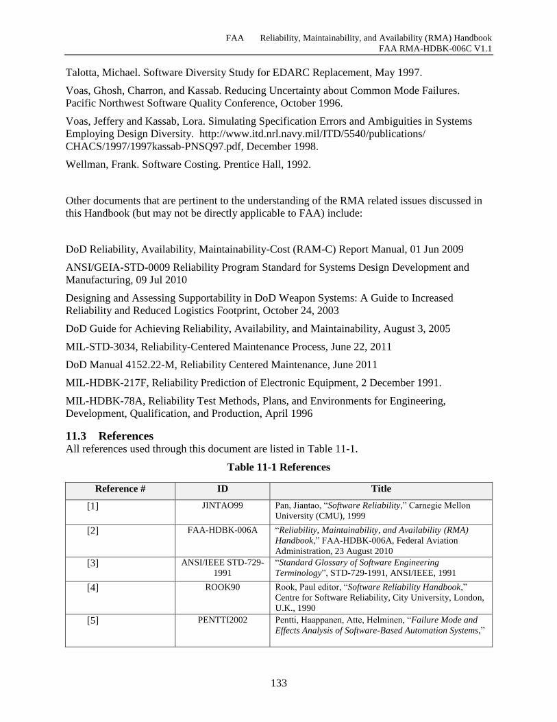
FAA Reliability, Maintainability, and Availability (RMA) Handbook
FAA RMA-HDBK-006C V1.1
133
Talotta, Michael. Software Diversity Study for EDARC Replacement, May 1997.
Voas, Ghosh, Charron, and Kassab. Reducing Uncertainty about Common Mode Failures.
Pacific Northwest Software Quality Conference, October 1996.
Voas, Jeffery and Kassab, Lora. Simulating Specification Errors and Ambiguities in Systems
Employing Design Diversity. http://www.itd.nrl.navy.mil/ITD/5540/publications/
CHACS/1997/1997kassab-PNSQ97.pdf, December 1998.
Wellman, Frank. Software Costing. Prentice Hall, 1992.
Other documents that are pertinent to the understanding of the RMA related issues discussed in
this Handbook (but may not be directly applicable to FAA) include:
DoD Reliability, Availability, Maintainability-Cost (RAM-C) Report Manual, 01 Jun 2009
ANSI/GEIA-STD-0009 Reliability Program Standard for Systems Design Development and
Manufacturing, 09 Jul 2010
Designing and Assessing Supportability in DoD Weapon Systems: A Guide to Increased
Reliability and Reduced Logistics Footprint, October 24, 2003
DoD Guide for Achieving Reliability, Availability, and Maintainability, August 3, 2005
MIL-STD-3034, Reliability-Centered Maintenance Process, June 22, 2011
DoD Manual 4152.22-M, Reliability Centered Maintenance, June 2011
MIL-HDBK-217F, Reliability Prediction of Electronic Equipment, 2 December 1991.
MIL-HDBK-78A, Reliability Test Methods, Plans, and Environments for Engineering,
Development, Qualification, and Production, April 1996
11.3 References All references used through this document are listed in Table 11-1.
Table 11-1 References
Reference # ID Title
[1] JINTAO99 Pan, Jiantao, “Software Reliability,” Carnegie Mellon
University (CMU), 1999
[2] FAA-HDBK-006A “Reliability, Maintainability, and Availability (RMA)
Handbook,” FAA-HDBK-006A, Federal Aviation
Administration, 23 August 2010
[3] ANSI/IEEE STD-729-
1991
“Standard Glossary of Software Engineering
Terminology”, STD-729-1991, ANSI/IEEE, 1991
[4] ROOK90 Rook, Paul editor, “Software Reliability Handbook,”
Centre for Software Reliability, City University, London,
U.K., 1990
[5] PENTTI2002 Pentti, Haappanen, Atte, Helminen, “Failure Mode and
Effects Analysis of Software-Based Automation Systems,”
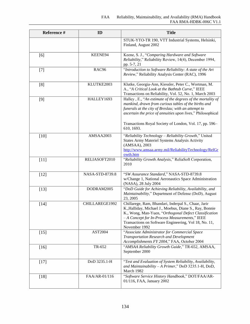
FAA Reliability, Maintainability, and Availability (RMA) Handbook
FAA RMA-HDBK-006C V1.1
134
Reference # ID Title
STUK-YTO-TR 190, VTT Industrial Systems, Helsinki,
Finland, August 2002
[6] KEENE94 Keene, S. J., “Comparing Hardware and Software
Reliability,” Reliability Review, 14(4), December 1994,
pp. 5-7, 21
[7] RAC96 “Introduction to Software Reliability: A state of the Art
Review,” Reliability Analysis Center (RAC), 1996
[8] KLUTKE2003 Klutke, Georgia-Ann, Kiessler, Peter C., Wortman, M.
A., “A Critical Look at the Bathtub Curve,” IEEE
Transactions on Reliability, Vol. 52, No. 1, March 2003
[9] HALLEY1693 Halley , E., “An estimate of the degrees of the mortality of
mankind, drawn from curious tables of the births and
funerals at the city of Breslau; with an attempt to
ascertain the price of annuities upon lives,” Philosophical
Transactions Royal Society of London, Vol. 17, pp. 596–
610, 1693.
[10] AMSAA2003 “Reliability Technology – Reliability Growth,” United
States Army Materiel Systems Analysis Activity
(AMSAA), 2003
http://www.amsaa.army.mil/ReliabilityTechnology/RelGr
owth.htm
[11] RELIASOFT2010 “Reliability Growth Analysis,” ReliaSoft Corporation,
2010
[12] NASA-STD-8739.8 “SW Assurance Standard,” NASA-STD-8739.8
w/Change 1, National Aeronautics Space Administration
(NASA), 28 July 2004
[13] DODRAM2005 “DoD Guide for Achieving Reliability, Availability, and
Maintainability,” Department of Defense (DoD), August
23, 2005
[14] CHILLAREGE1992 Chillarege, Ram, Bhandari, Inderpal S., Chaar, Jarir
K.,Halliday, Michael J., Moebus, Diane S., Ray, Bonnie
K., Wong, Man-Yuen, “Orthogonal Defect Classification
– A Concept for In-Process Measurements,” IEEE
Transactions on Software Engineering, Vol 18, No. 11,
November 1992
[15] AST2004 “Associate Administrator for Commercial Space
Transportation Research and Development
Accomplishments FY 2004,” FAA, October 2004
[16] TR-652 “AMSAA Reliability Growth Guide,” TR-652, AMSAA,
September 2000
[17] DoD 3235.1-H “Test and Evaluation of System Reliability, Availability,
and Maintainability – A Primer,” DoD 3235.1-H, DoD,
March 1982
[18] FAA/AR-01/116 “Software Service History Handbook,” DOT/FAA/AR-
01/116, FAA, January 2002
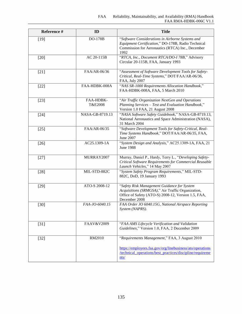
FAA Reliability, Maintainability, and Availability (RMA) Handbook
FAA RMA-HDBK-006C V1.1
135
Reference # ID Title
[19] DO-178B “Software Considerations in Airborne Systems and
Equipment Certification,” DO-178B, Radio Technical
Commission for Aeronautics (RTCA) Inc., December
1992
[20] AC 20-115B “RTCA, Inc., Document RTCA/DO-I 78B,” Advisory
Circular 20-115B, FAA, January 1993
[21] FAA/AR-06/36 “Assessment of Software Development Tools for Safety-
Critical, Real-Time Systems,” DOT/FAA/AR-06/36,
FAA, July 2007
[22] FAA-HDBK-008A “NAS SR-1000 Requirements Allocation Handbook,”
FAA-HDBK-008A, FAA, 5 March 2010
[23] FAA-HDBK-
T&E2008
“Air Traffic Organization NextGen and Operations
Planning Services – Test and Evaluation Handbook,”
Version 1.0 FAA, 21 August 2008
[24] NASA-GB-8719.13 “NASA Software Safety Guidebook,” NASA-GB-8719.13,
National Aeronautics and Space Administration (NASA),
31 March 2004
[25] FAA/AR-06/35 “Software Development Tools for Safety-Critical, Real-
Time Systems Handbook,” DOT/FAA/AR-06/35, FAA,
June 2007
[26] AC25.1309-1A “System Design and Analysis,” AC25.1309-1A, FAA, 21
June 1988
[27] MURRAY2007 Murray, Daniel P., Hardy, Terry L., “Developing Safety-
Critical Software Requirements for Commercial Reusable
Launch Vehicles,” 14 May 2007
[28] MIL-STD-882C “System Safety Program Requirements,” MIL-STD-
882C, DoD, 19 January 1993
[29] ATO-S 2008-12 “Safety Risk Management Guidance for System
Acquisitions (SRMGSA),” Air Traffic Organization,
Office of Safety (ATO-S) 2008-12, Version 1.5, FAA,
December 2008
[30] FAA-JO-6040.15 FAA Order JO 6040.15G, National Airspace Reporting
System (NAPRS).
[31] FAAV&V2009 “FAA AMS Lifecycle Verification and Validation
Guidelines,” Version 1.0, FAA, 2 December 2009
[32] RM2010 “Requirements Management,” FAA, 3 August 2010
https://employees.faa.gov/org/linebusiness/ato/operations
/technical_operations/best_practices/discipline/requireme
nts/
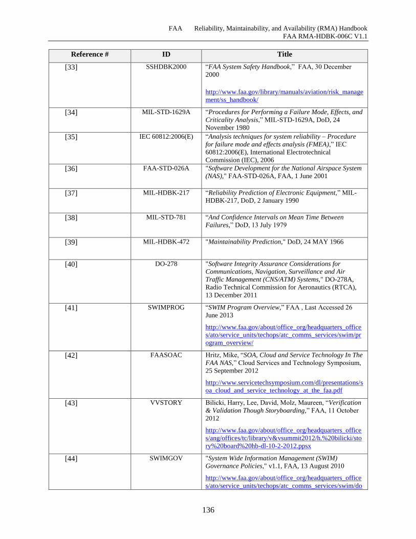
FAA Reliability, Maintainability, and Availability (RMA) Handbook
FAA RMA-HDBK-006C V1.1
136
Reference # ID Title
[33] SSHDBK2000 “FAA System Safety Handbook,” FAA, 30 December
2000
http://www.faa.gov/library/manuals/aviation/risk_manage
ment/ss_handbook/
[34] MIL-STD-1629A “Procedures for Performing a Failure Mode, Effects, and
Criticality Analysis,” MIL-STD-1629A, DoD, 24
November 1980
[35] IEC 60812:2006(E) “Analysis techniques for system reliability – Procedure
for failure mode and effects analysis (FMEA),” IEC
60812:2006(E), International Electrotechnical
Commission (IEC), 2006
[36] FAA-STD-026A "Software Development for the National Airspace System
(NAS)," FAA-STD-026A, FAA, 1 June 2001
[37] MIL-HDBK-217 “Reliability Prediction of Electronic Equipment,” MIL-
HDBK-217, DoD, 2 January 1990
[38] MIL-STD-781 “And Confidence Intervals on Mean Time Between
Failures,” DoD, 13 July 1979
[39] MIL-HDBK-472 "Maintainability Prediction," DoD, 24 MAY 1966
[40] DO-278 "Software Integrity Assurance Considerations for
Communications, Navigation, Surveillance and Air
Traffic Management (CNS/ATM) Systems," DO-278A,
Radio Technical Commission for Aeronautics (RTCA),
13 December 2011
[41] SWIMPROG “SWIM Program Overview,” FAA , Last Accessed 26
June 2013
http://www.faa.gov/about/office_org/headquarters_office
s/ato/service_units/techops/atc_comms_services/swim/pr
ogram_overview/
[42] FAASOAC Hritz, Mike, “SOA, Cloud and Service Technology In The
FAA NAS,” Cloud Services and Technology Symposium,
25 September 2012
http://www.servicetechsymposium.com/dl/presentations/s
oa_cloud_and_service_technology_at_the_faa.pdf
[43] VVSTORY Bilicki, Harry, Lee, David, Molz, Maureen, “Verification
& Validation Though Storyboarding,” FAA, 11 October
2012
http://www.faa.gov/about/office_org/headquarters_office
s/ang/offices/tc/library/v&vsummit2012/h.%20bilicki/sto
ry%20board%20hb-dl-10-2-2012.ppsx
[44] SWIMGOV "System Wide Information Management (SWIM)
Governance Policies," v1.1, FAA, 13 August 2010
http://www.faa.gov/about/office_org/headquarters_office
s/ato/service_units/techops/atc_comms_services/swim/do
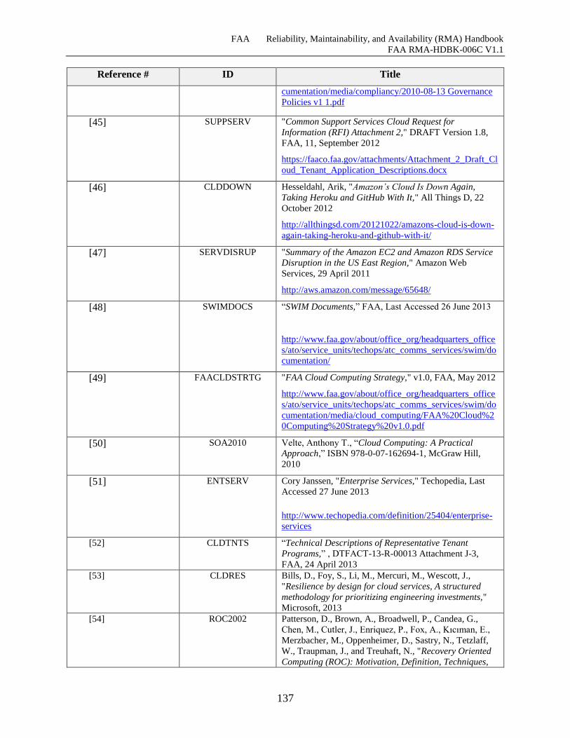
FAA Reliability, Maintainability, and Availability (RMA) Handbook
FAA RMA-HDBK-006C V1.1
137
Reference # ID Title
cumentation/media/compliancy/2010-08-13 Governance
Policies v1 1.pdf
[45] SUPPSERV "Common Support Services Cloud Request for
Information (RFI) Attachment 2," DRAFT Version 1.8,
FAA, 11, September 2012
https://faaco.faa.gov/attachments/Attachment_2_Draft_Cl
oud_Tenant_Application_Descriptions.docx
[46] CLDDOWN Hesseldahl, Arik, "Amazon’s Cloud Is Down Again,
Taking Heroku and GitHub With It," All Things D, 22
October 2012
http://allthingsd.com/20121022/amazons-cloud-is-down-
again-taking-heroku-and-github-with-it/
[47] SERVDISRUP "Summary of the Amazon EC2 and Amazon RDS Service
Disruption in the US East Region," Amazon Web
Services, 29 April 2011
http://aws.amazon.com/message/65648/
[48] SWIMDOCS “SWIM Documents,” FAA, Last Accessed 26 June 2013
http://www.faa.gov/about/office_org/headquarters_office
s/ato/service_units/techops/atc_comms_services/swim/do
cumentation/
[49] FAACLDSTRTG "FAA Cloud Computing Strategy," v1.0, FAA, May 2012
http://www.faa.gov/about/office_org/headquarters_office
s/ato/service_units/techops/atc_comms_services/swim/do
cumentation/media/cloud_computing/FAA%20Cloud%2
0Computing%20Strategy%20v1.0.pdf
[50] SOA2010 Velte, Anthony T., “Cloud Computing: A Practical
Approach,” ISBN 978-0-07-162694-1, McGraw Hill,
2010
[51] ENTSERV Cory Janssen, "Enterprise Services," Techopedia, Last
Accessed 27 June 2013
http://www.techopedia.com/definition/25404/enterprise-
services
[52] CLDTNTS “Technical Descriptions of Representative Tenant
Programs,” , DTFACT-13-R-00013 Attachment J-3,
FAA, 24 April 2013
[53] CLDRES Bills, D., Foy, S., Li, M., Mercuri, M., Wescott, J.,
"Resilience by design for cloud services, A structured
methodology for prioritizing engineering investments,"
Microsoft, 2013
[54] ROC2002 Patterson, D., Brown, A., Broadwell, P., Candea, G.,
Chen, M., Cutler, J., Enriquez, P., Fox, A., Kıcıman, E.,
Merzbacher, M., Oppenheimer, D., Sastry, N., Tetzlaff,
W., Traupman, J., and Treuhaft, N., "Recovery Oriented
Computing (ROC): Motivation, Definition, Techniques,
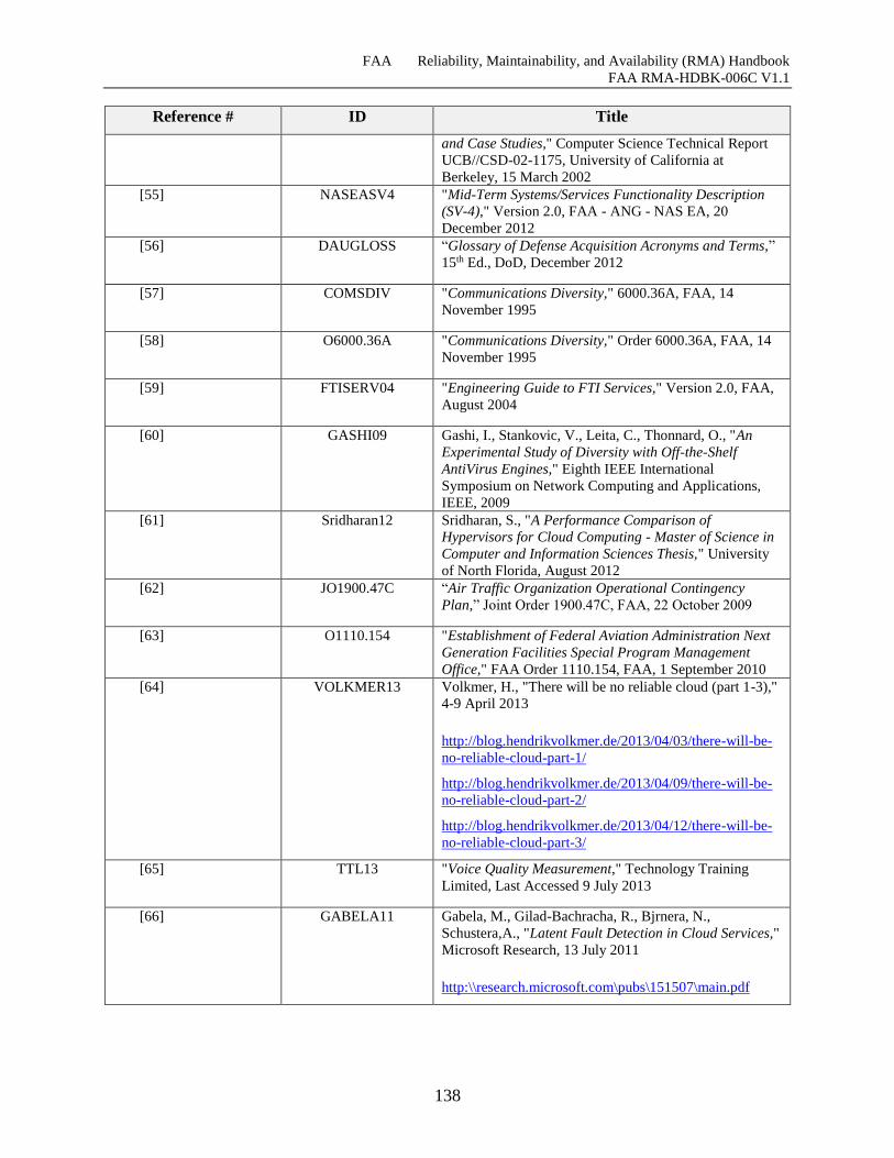
FAA Reliability, Maintainability, and Availability (RMA) Handbook
FAA RMA-HDBK-006C V1.1
138
Reference # ID Title
and Case Studies," Computer Science Technical Report
UCB//CSD-02-1175, University of California at
Berkeley, 15 March 2002
[55] NASEASV4 "Mid-Term Systems/Services Functionality Description
(SV-4)," Version 2.0, FAA - ANG - NAS EA, 20
December 2012
[56] DAUGLOSS “Glossary of Defense Acquisition Acronyms and Terms,”
15th Ed., DoD, December 2012
[57] COMSDIV "Communications Diversity," 6000.36A, FAA, 14
November 1995
[58] O6000.36A "Communications Diversity," Order 6000.36A, FAA, 14
November 1995
[59] FTISERV04 "Engineering Guide to FTI Services," Version 2.0, FAA,
August 2004
[60] GASHI09 Gashi, I., Stankovic, V., Leita, C., Thonnard, O., "An
Experimental Study of Diversity with Off-the-Shelf
AntiVirus Engines," Eighth IEEE International
Symposium on Network Computing and Applications,
IEEE, 2009
[61] Sridharan12 Sridharan, S., "A Performance Comparison of
Hypervisors for Cloud Computing - Master of Science in
Computer and Information Sciences Thesis," University
of North Florida, August 2012
[62] JO1900.47C “Air Traffic Organization Operational Contingency
Plan,” Joint Order 1900.47C, FAA, 22 October 2009
[63] O1110.154 "Establishment of Federal Aviation Administration Next
Generation Facilities Special Program Management
Office," FAA Order 1110.154, FAA, 1 September 2010
[64] VOLKMER13 Volkmer, H., "There will be no reliable cloud (part 1-3),"
4-9 April 2013
http://blog.hendrikvolkmer.de/2013/04/03/there-will-be-
no-reliable-cloud-part-1/
http://blog.hendrikvolkmer.de/2013/04/09/there-will-be-
no-reliable-cloud-part-2/
http://blog.hendrikvolkmer.de/2013/04/12/there-will-be-
no-reliable-cloud-part-3/
[65] TTL13 "Voice Quality Measurement," Technology Training
Limited, Last Accessed 9 July 2013
[66] GABELA11 Gabela, M., Gilad-Bachracha, R., Bjrnera, N.,
Schustera,A., "Latent Fault Detection in Cloud Services,"
Microsoft Research, 13 July 2011
http:\\research.microsoft.com\pubs\151507\main.pdf
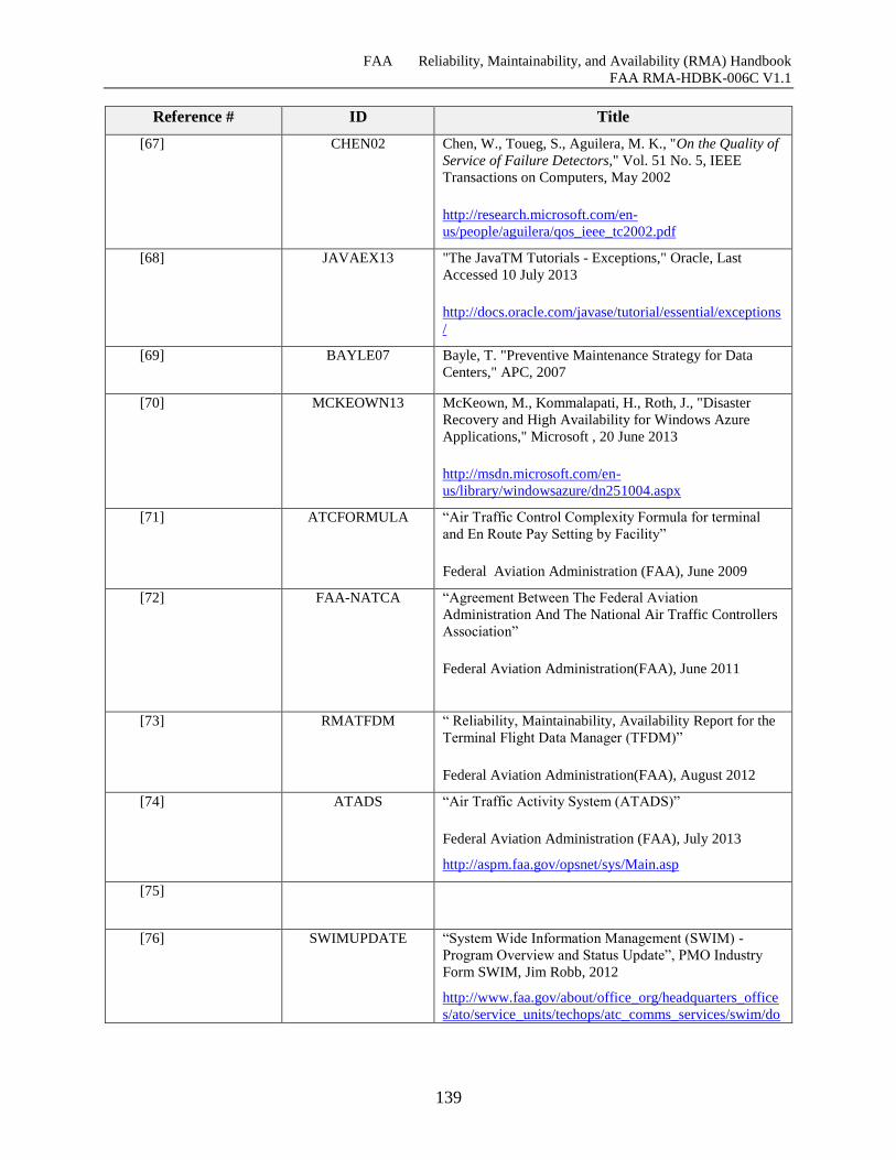
FAA Reliability, Maintainability, and Availability (RMA) Handbook
FAA RMA-HDBK-006C V1.1
139
Reference # ID Title
[67] CHEN02 Chen, W., Toueg, S., Aguilera, M. K., "On the Quality of
Service of Failure Detectors," Vol. 51 No. 5, IEEE
Transactions on Computers, May 2002
http://research.microsoft.com/en-
us/people/aguilera/qos_ieee_tc2002.pdf
[68] JAVAEX13 "The JavaTM Tutorials - Exceptions," Oracle, Last
Accessed 10 July 2013
http://docs.oracle.com/javase/tutorial/essential/exceptions
/
[69] BAYLE07 Bayle, T. "Preventive Maintenance Strategy for Data
Centers," APC, 2007
[70] MCKEOWN13 McKeown, M., Kommalapati, H., Roth, J., "Disaster
Recovery and High Availability for Windows Azure
Applications," Microsoft , 20 June 2013
http://msdn.microsoft.com/en-
us/library/windowsazure/dn251004.aspx
[71] ATCFORMULA “Air Traffic Control Complexity Formula for terminal
and En Route Pay Setting by Facility”
Federal Aviation Administration (FAA), June 2009
[72] FAA-NATCA “Agreement Between The Federal Aviation
Administration And The National Air Traffic Controllers
Association”
Federal Aviation Administration(FAA), June 2011
[73] RMATFDM “ Reliability, Maintainability, Availability Report for the
Terminal Flight Data Manager (TFDM)”
Federal Aviation Administration(FAA), August 2012
[74] ATADS “Air Traffic Activity System (ATADS)”
Federal Aviation Administration (FAA), July 2013
http://aspm.faa.gov/opsnet/sys/Main.asp
[75]
[76] SWIMUPDATE “System Wide Information Management (SWIM) -
Program Overview and Status Update”, PMO Industry
Form SWIM, Jim Robb, 2012
http://www.faa.gov/about/office_org/headquarters_office
s/ato/service_units/techops/atc_comms_services/swim/do
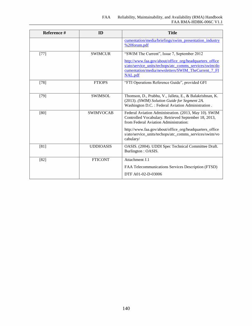
FAA Reliability, Maintainability, and Availability (RMA) Handbook
FAA RMA-HDBK-006C V1.1
140
Reference # ID Title
cumentation/media/briefings/swim_presentation_industry
%20forum.pdf
[77] SWIMCUR “SWIM The Current”, Issue 7, September 2012
http://www.faa.gov/about/office_org/headquarters_office
s/ato/service_units/techops/atc_comms_services/swim/do
cumentation/media/newsletters/SWIM_TheCurrent_7_FI
NAL.pdf
[78] FTIOPS “FTI Operations Reference Guide”, provided GFI
[79] SWIMSOL Thomson, D., Prabhu, V., Jalleta, E., & Balakrishnan, K.
(2013). (SWIM) Solution Guide for Segment 2A.
Washington D.C. : Federal Aviation Administration .
[80] SWIMVOCAB Federal Aviation Administration. (2013, May 10). SWIM
Controlled Vocabulary. Retrieved September 18, 2013,
from Federal Aviation Administration:
http://www.faa.gov/about/office_org/headquarters_office
s/ato/service_units/techops/atc_comms_services/swim/vo
cabulary/
[81] UDDIOASIS OASIS. (2004). UDDI Spec Technical Committee Draft.
Burlington : OASIS.
[82] FTICONT Attachment J.1
FAA Telecommunications Services Description (FTSD)
DTF A01-02-D-03006
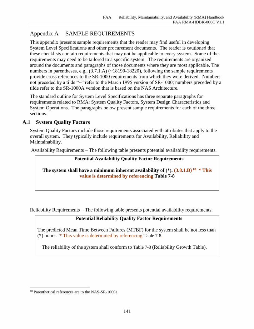
FAA Reliability, Maintainability, and Availability (RMA) Handbook
FAA RMA-HDBK-006C V1.1
141
Appendix A SAMPLE REQUIREMENTS
This appendix presents sample requirements that the reader may find useful in developing
System Level Specifications and other procurement documents. The reader is cautioned that
these checklists contain requirements that may not be applicable to every system. Some of the
requirements may need to be tailored to a specific system. The requirements are organized
around the documents and paragraphs of those documents where they are most applicable. The
numbers in parentheses, e.g., (3.7.1.A) (~18190-18220), following the sample requirements
provide cross references to the SR-1000 requirements from which they were derived. Numbers
not preceded by a tilde “~” refer to the March 1995 version of SR-1000; numbers preceded by a
tilde refer to the SR-1000A version that is based on the NAS Architecture.
The standard outline for System Level Specifications has three separate paragraphs for
requirements related to RMA: System Quality Factors, System Design Characteristics and
System Operations. The paragraphs below present sample requirements for each of the three
sections.
A.1 System Quality Factors
System Quality Factors include those requirements associated with attributes that apply to the
overall system. They typically include requirements for Availability, Reliability and
Maintainability.
Availability Requirements – The following table presents potential availability requirements.
Potential Availability Quality Factor Requirements
The system shall have a minimum inherent availability of (*). (3.8.1.B) 18 * This
value is determined by referencing Table 7-8
Reliability Requirements – The following table presents potential availability requirements.
Potential Reliability Quality Factor Requirements
The predicted Mean Time Between Failures (MTBF) for the system shall be not less than
(*) hours. * This value is determined by referencing Table 7-8.
The reliability of the system shall conform to Table 7-8 (Reliability Growth Table).
18 Parenthetical references are to the NAS-SR-1000a.
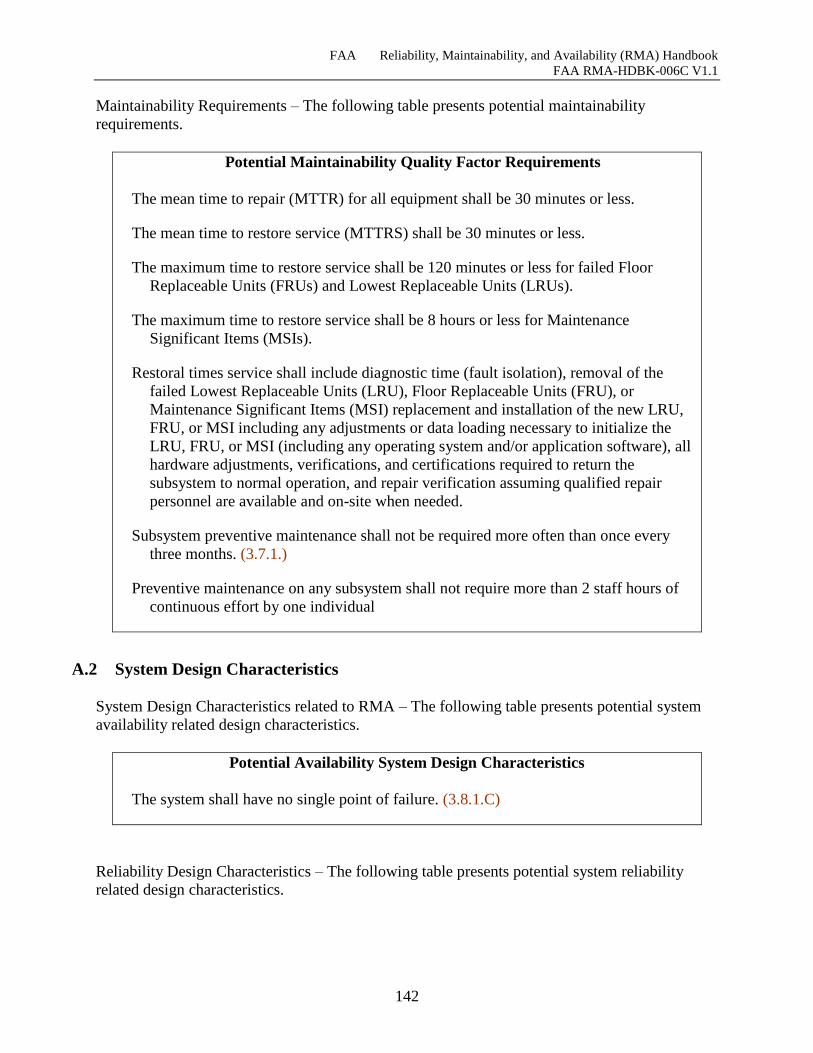
FAA Reliability, Maintainability, and Availability (RMA) Handbook
FAA RMA-HDBK-006C V1.1
142
Maintainability Requirements – The following table presents potential maintainability
requirements.
Potential Maintainability Quality Factor Requirements
The mean time to repair (MTTR) for all equipment shall be 30 minutes or less.
The mean time to restore service (MTTRS) shall be 30 minutes or less.
The maximum time to restore service shall be 120 minutes or less for failed Floor
Replaceable Units (FRUs) and Lowest Replaceable Units (LRUs).
The maximum time to restore service shall be 8 hours or less for Maintenance
Significant Items (MSIs).
Restoral times service shall include diagnostic time (fault isolation), removal of the
failed Lowest Replaceable Units (LRU), Floor Replaceable Units (FRU), or
Maintenance Significant Items (MSI) replacement and installation of the new LRU,
FRU, or MSI including any adjustments or data loading necessary to initialize the
LRU, FRU, or MSI (including any operating system and/or application software), all
hardware adjustments, verifications, and certifications required to return the
subsystem to normal operation, and repair verification assuming qualified repair
personnel are available and on-site when needed.
Subsystem preventive maintenance shall not be required more often than once every
three months. (3.7.1.)
Preventive maintenance on any subsystem shall not require more than 2 staff hours of
continuous effort by one individual
A.2 System Design Characteristics
System Design Characteristics related to RMA – The following table presents potential system
availability related design characteristics.
Potential Availability System Design Characteristics
The system shall have no single point of failure. (3.8.1.C)
Reliability Design Characteristics – The following table presents potential system reliability
related design characteristics.
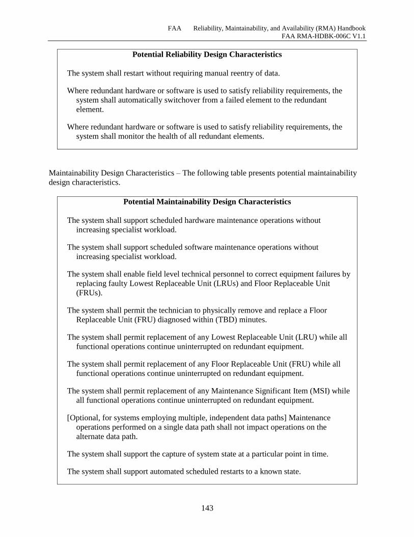
FAA Reliability, Maintainability, and Availability (RMA) Handbook
FAA RMA-HDBK-006C V1.1
143
Potential Reliability Design Characteristics
The system shall restart without requiring manual reentry of data.
Where redundant hardware or software is used to satisfy reliability requirements, the
system shall automatically switchover from a failed element to the redundant
element.
Where redundant hardware or software is used to satisfy reliability requirements, the
system shall monitor the health of all redundant elements.
Maintainability Design Characteristics – The following table presents potential maintainability
design characteristics.
Potential Maintainability Design Characteristics
The system shall support scheduled hardware maintenance operations without
increasing specialist workload.
The system shall support scheduled software maintenance operations without
increasing specialist workload.
The system shall enable field level technical personnel to correct equipment failures by
replacing faulty Lowest Replaceable Unit (LRUs) and Floor Replaceable Unit
(FRUs).
The system shall permit the technician to physically remove and replace a Floor
Replaceable Unit (FRU) diagnosed within (TBD) minutes.
The system shall permit replacement of any Lowest Replaceable Unit (LRU) while all
functional operations continue uninterrupted on redundant equipment.
The system shall permit replacement of any Floor Replaceable Unit (FRU) while all
functional operations continue uninterrupted on redundant equipment.
The system shall permit replacement of any Maintenance Significant Item (MSI) while
all functional operations continue uninterrupted on redundant equipment.
[Optional, for systems employing multiple, independent data paths] Maintenance
operations performed on a single data path shall not impact operations on the
alternate data path.
The system shall support the capture of system state at a particular point in time.
The system shall support automated scheduled restarts to a known state.
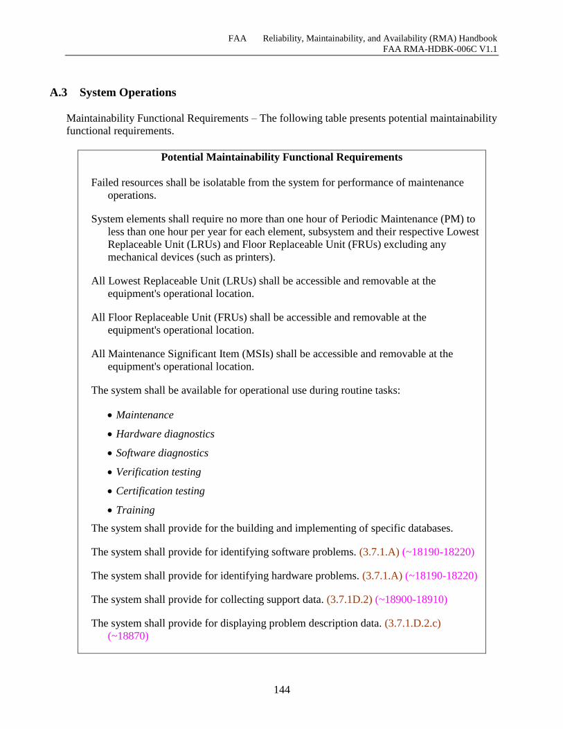
FAA Reliability, Maintainability, and Availability (RMA) Handbook
FAA RMA-HDBK-006C V1.1
144
A.3 System Operations
Maintainability Functional Requirements – The following table presents potential maintainability
functional requirements.
Potential Maintainability Functional Requirements
Failed resources shall be isolatable from the system for performance of maintenance
operations.
System elements shall require no more than one hour of Periodic Maintenance (PM) to
less than one hour per year for each element, subsystem and their respective Lowest
Replaceable Unit (LRUs) and Floor Replaceable Unit (FRUs) excluding any
mechanical devices (such as printers).
All Lowest Replaceable Unit (LRUs) shall be accessible and removable at the
equipment's operational location.
All Floor Replaceable Unit (FRUs) shall be accessible and removable at the
equipment's operational location.
All Maintenance Significant Item (MSIs) shall be accessible and removable at the
equipment's operational location.
The system shall be available for operational use during routine tasks:
Maintenance
Hardware diagnostics
Software diagnostics
Verification testing
Certification testing
Training
The system shall provide for the building and implementing of specific databases.
The system shall provide for identifying software problems. (3.7.1.A) (~18190-18220)
The system shall provide for identifying hardware problems. (3.7.1.A) (~18190-18220)
The system shall provide for collecting support data. (3.7.1D.2) (~18900-18910)
The system shall provide for displaying problem description data. (3.7.1.D.2.c)
(~18870)
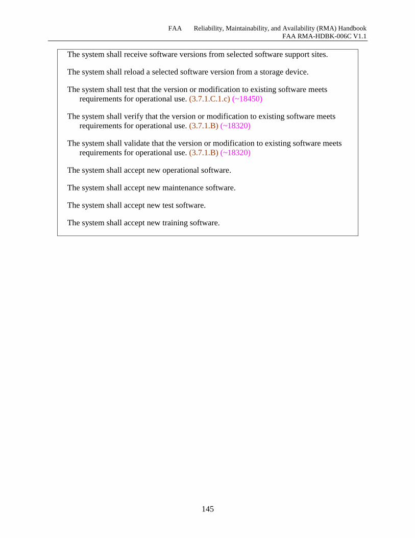
FAA Reliability, Maintainability, and Availability (RMA) Handbook
FAA RMA-HDBK-006C V1.1
145
The system shall receive software versions from selected software support sites.
The system shall reload a selected software version from a storage device.
The system shall test that the version or modification to existing software meets
requirements for operational use. (3.7.1.C.1.c) (~18450)
The system shall verify that the version or modification to existing software meets
requirements for operational use. (3.7.1.B) (~18320)
The system shall validate that the version or modification to existing software meets
requirements for operational use. (3.7.1.B) (~18320)
The system shall accept new operational software.
The system shall accept new maintenance software.
The system shall accept new test software.
The system shall accept new training software.

FAA Reliability, Maintainability, and Availability (RMA) Handbook
FAA RMA-HDBK-006C V1.1
146
Monitor and Control – The following table presents potential Monitor and Control (M&C)
General functional requirements.
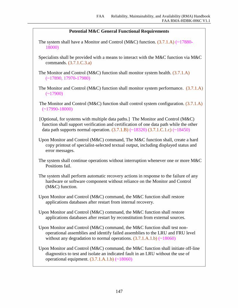
FAA Reliability, Maintainability, and Availability (RMA) Handbook
FAA RMA-HDBK-006C V1.1
147
Potential M&C General Functional Requirements
The system shall have a Monitor and Control (M&C) function. (3.7.1.A) (~17880-
18000)
Specialists shall be provided with a means to interact with the M&C function via M&C
commands. (3.7.1.C.3.a)
The Monitor and Control (M&C) function shall monitor system health. (3.7.1.A)
(~17890, 17970-17980)
The Monitor and Control (M&C) function shall monitor system performance. (3.7.1.A)
(~17900)
The Monitor and Control (M&C) function shall control system configuration. (3.7.1.A)
(~17990-18000)
[Optional, for systems with multiple data paths.] The Monitor and Control (M&C)
function shall support verification and certification of one data path while the other
data path supports normal operation. (3.7.1.B) (~18320) (3.7.1.C.1.c) (~18450)
Upon Monitor and Control (M&C) command, The M&C function shall, create a hard
copy printout of specialist-selected textual output, including displayed status and
error messages.
The system shall continue operations without interruption whenever one or more M&C
Positions fail.
The system shall perform automatic recovery actions in response to the failure of any
hardware or software component without reliance on the Monitor and Control
(M&C) function.
Upon Monitor and Control (M&C) command, the M&C function shall restore
applications databases after restart from internal recovery.
Upon Monitor and Control (M&C) command, the M&C function shall restore
applications databases after restart by reconstitution from external sources.
Upon Monitor and Control (M&C) command, the M&C function shall test non-
operational assemblies and identify failed assemblies to the LRU and FRU level
without any degradation to normal operations. (3.7.1.A.1.b) (~18060)
Upon Monitor and Control (M&C) command, the M&C function shall initiate off-line
diagnostics to test and isolate an indicated fault in an LRU without the use of
operational equipment. (3.7.1.A.1.b) (~18060)
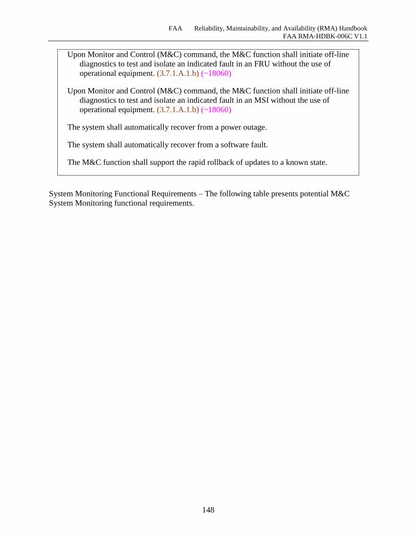
FAA Reliability, Maintainability, and Availability (RMA) Handbook
FAA RMA-HDBK-006C V1.1
148
Upon Monitor and Control (M&C) command, the M&C function shall initiate off-line
diagnostics to test and isolate an indicated fault in an FRU without the use of
operational equipment. (3.7.1.A.1.b) (~18060)
Upon Monitor and Control (M&C) command, the M&C function shall initiate off-line
diagnostics to test and isolate an indicated fault in an MSI without the use of
operational equipment. (3.7.1.A.1.b) (~18060)
The system shall automatically recover from a power outage.
The system shall automatically recover from a software fault.
The M&C function shall support the rapid rollback of updates to a known state.
System Monitoring Functional Requirements – The following table presents potential M&C
System Monitoring functional requirements.
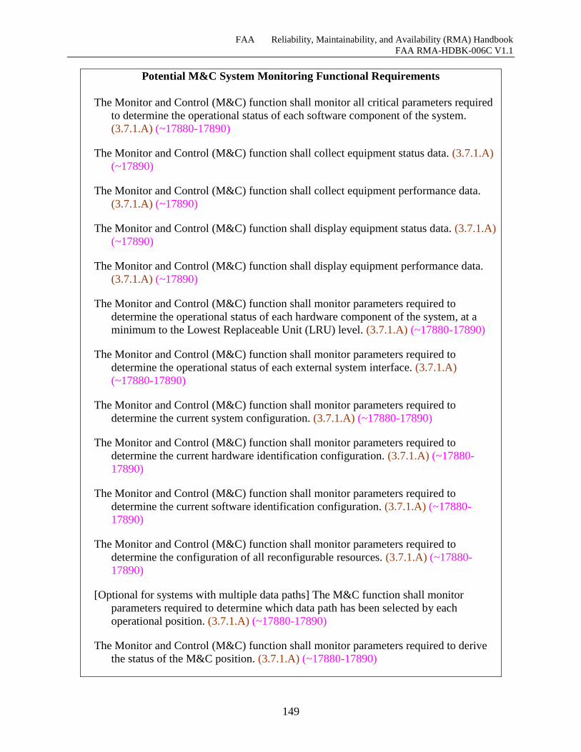
FAA Reliability, Maintainability, and Availability (RMA) Handbook
FAA RMA-HDBK-006C V1.1
149
Potential M&C System Monitoring Functional Requirements
The Monitor and Control (M&C) function shall monitor all critical parameters required
to determine the operational status of each software component of the system.
(3.7.1.A) (~17880-17890)
The Monitor and Control (M&C) function shall collect equipment status data. (3.7.1.A)
(~17890)
The Monitor and Control (M&C) function shall collect equipment performance data.
(3.7.1.A) (~17890)
The Monitor and Control (M&C) function shall display equipment status data. (3.7.1.A)
(~17890)
The Monitor and Control (M&C) function shall display equipment performance data.
(3.7.1.A) (~17890)
The Monitor and Control (M&C) function shall monitor parameters required to
determine the operational status of each hardware component of the system, at a
minimum to the Lowest Replaceable Unit (LRU) level. (3.7.1.A) (~17880-17890)
The Monitor and Control (M&C) function shall monitor parameters required to
determine the operational status of each external system interface. (3.7.1.A)
(~17880-17890)
The Monitor and Control (M&C) function shall monitor parameters required to
determine the current system configuration. (3.7.1.A) (~17880-17890)
The Monitor and Control (M&C) function shall monitor parameters required to
determine the current hardware identification configuration. (3.7.1.A) (~17880-
17890)
The Monitor and Control (M&C) function shall monitor parameters required to
determine the current software identification configuration. (3.7.1.A) (~17880-
17890)
The Monitor and Control (M&C) function shall monitor parameters required to
determine the configuration of all reconfigurable resources. (3.7.1.A) (~17880-
17890)
[Optional for systems with multiple data paths] The M&C function shall monitor
parameters required to determine which data path has been selected by each
operational position. (3.7.1.A) (~17880-17890)
The Monitor and Control (M&C) function shall monitor parameters required to derive
the status of the M&C position. (3.7.1.A) (~17880-17890)
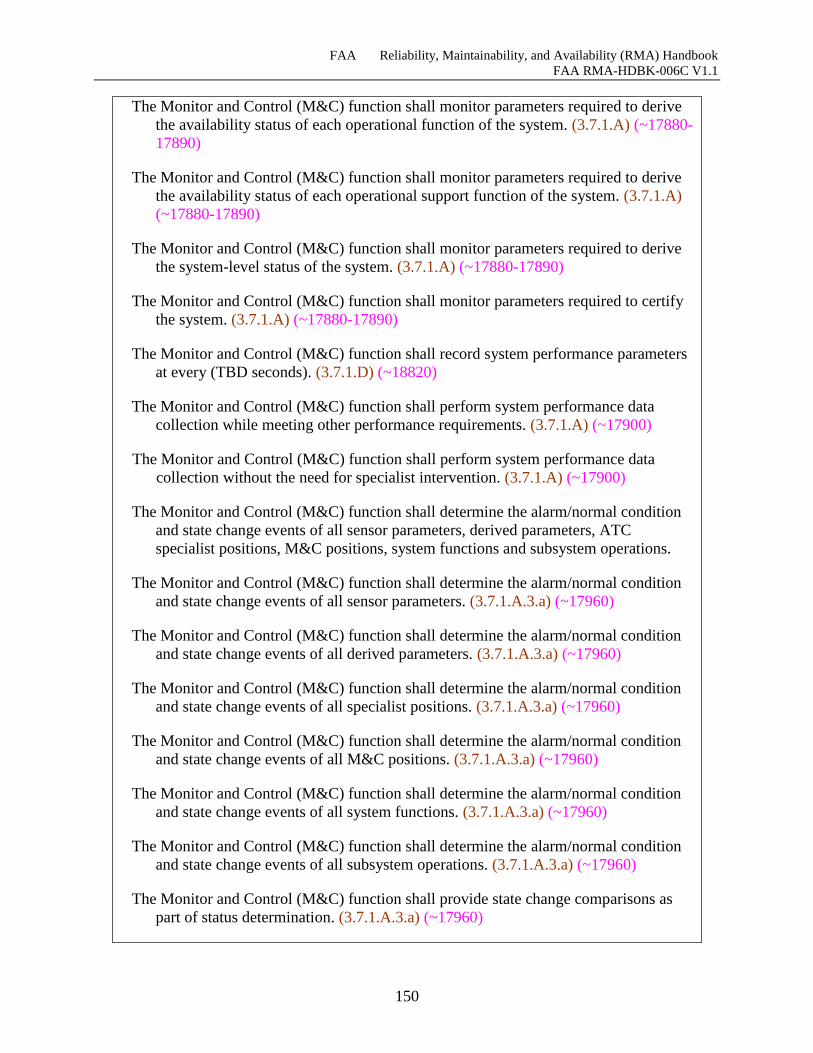
FAA Reliability, Maintainability, and Availability (RMA) Handbook
FAA RMA-HDBK-006C V1.1
150
The Monitor and Control (M&C) function shall monitor parameters required to derive
the availability status of each operational function of the system. (3.7.1.A) (~17880-
17890)
The Monitor and Control (M&C) function shall monitor parameters required to derive
the availability status of each operational support function of the system. (3.7.1.A)
(~17880-17890)
The Monitor and Control (M&C) function shall monitor parameters required to derive
the system-level status of the system. (3.7.1.A) (~17880-17890)
The Monitor and Control (M&C) function shall monitor parameters required to certify
the system. (3.7.1.A) (~17880-17890)
The Monitor and Control (M&C) function shall record system performance parameters
at every (TBD seconds). (3.7.1.D) (~18820)
The Monitor and Control (M&C) function shall perform system performance data
collection while meeting other performance requirements. (3.7.1.A) (~17900)
The Monitor and Control (M&C) function shall perform system performance data
collection without the need for specialist intervention. (3.7.1.A) (~17900)
The Monitor and Control (M&C) function shall determine the alarm/normal condition
and state change events of all sensor parameters, derived parameters, ATC
specialist positions, M&C positions, system functions and subsystem operations.
The Monitor and Control (M&C) function shall determine the alarm/normal condition
and state change events of all sensor parameters. (3.7.1.A.3.a) (~17960)
The Monitor and Control (M&C) function shall determine the alarm/normal condition
and state change events of all derived parameters. (3.7.1.A.3.a) (~17960)
The Monitor and Control (M&C) function shall determine the alarm/normal condition
and state change events of all specialist positions. (3.7.1.A.3.a) (~17960)
The Monitor and Control (M&C) function shall determine the alarm/normal condition
and state change events of all M&C positions. (3.7.1.A.3.a) (~17960)
The Monitor and Control (M&C) function shall determine the alarm/normal condition
and state change events of all system functions. (3.7.1.A.3.a) (~17960)
The Monitor and Control (M&C) function shall determine the alarm/normal condition
and state change events of all subsystem operations. (3.7.1.A.3.a) (~17960)
The Monitor and Control (M&C) function shall provide state change comparisons as
part of status determination. (3.7.1.A.3.a) (~17960)
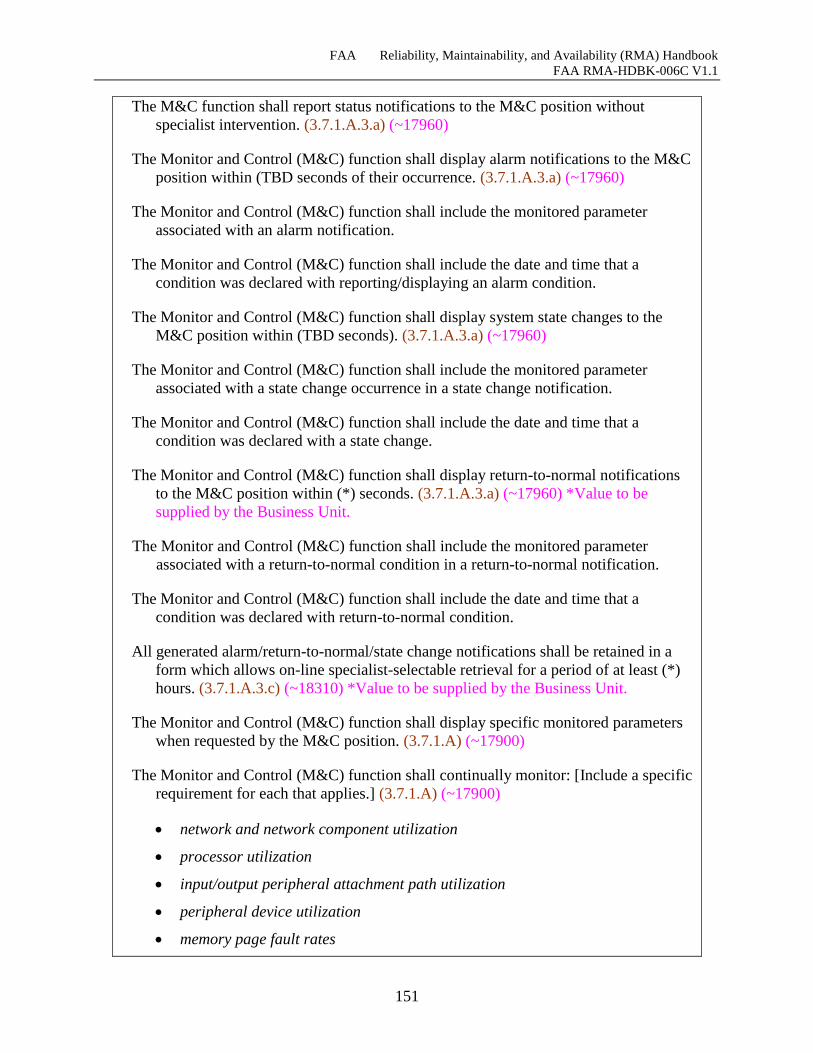
FAA Reliability, Maintainability, and Availability (RMA) Handbook
FAA RMA-HDBK-006C V1.1
151
The M&C function shall report status notifications to the M&C position without
specialist intervention. (3.7.1.A.3.a) (~17960)
The Monitor and Control (M&C) function shall display alarm notifications to the M&C
position within (TBD seconds of their occurrence. (3.7.1.A.3.a) (~17960)
The Monitor and Control (M&C) function shall include the monitored parameter
associated with an alarm notification.
The Monitor and Control (M&C) function shall include the date and time that a
condition was declared with reporting/displaying an alarm condition.
The Monitor and Control (M&C) function shall display system state changes to the
M&C position within (TBD seconds). (3.7.1.A.3.a) (~17960)
The Monitor and Control (M&C) function shall include the monitored parameter
associated with a state change occurrence in a state change notification.
The Monitor and Control (M&C) function shall include the date and time that a
condition was declared with a state change.
The Monitor and Control (M&C) function shall display return-to-normal notifications
to the M&C position within (*) seconds. (3.7.1.A.3.a) (~17960) *Value to be
supplied by the Business Unit.
The Monitor and Control (M&C) function shall include the monitored parameter
associated with a return-to-normal condition in a return-to-normal notification.
The Monitor and Control (M&C) function shall include the date and time that a
condition was declared with return-to-normal condition.
All generated alarm/return-to-normal/state change notifications shall be retained in a
form which allows on-line specialist-selectable retrieval for a period of at least (*)
hours. (3.7.1.A.3.c) (~18310) *Value to be supplied by the Business Unit.
The Monitor and Control (M&C) function shall display specific monitored parameters
when requested by the M&C position. (3.7.1.A) (~17900)
The Monitor and Control (M&C) function shall continually monitor: [Include a specific
requirement for each that applies.] (3.7.1.A) (~17900)
network and network component utilization
processor utilization
input/output peripheral attachment path utilization
peripheral device utilization
memory page fault rates
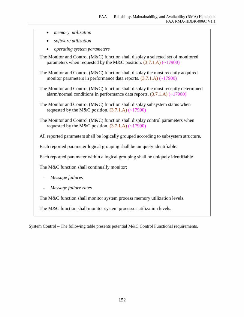
FAA Reliability, Maintainability, and Availability (RMA) Handbook
FAA RMA-HDBK-006C V1.1
152
memory utilization
software utilization
operating system parameters
The Monitor and Control (M&C) function shall display a selected set of monitored
parameters when requested by the M&C position. (3.7.1.A) (~17900)
The Monitor and Control (M&C) function shall display the most recently acquired
monitor parameters in performance data reports. (3.7.1.A) (~17900)
The Monitor and Control (M&C) function shall display the most recently determined
alarm/normal conditions in performance data reports. (3.7.1.A) (~17900)
The Monitor and Control (M&C) function shall display subsystem status when
requested by the M&C position. (3.7.1.A) (~17900)
The Monitor and Control (M&C) function shall display control parameters when
requested by the M&C position. (3.7.1.A) (~17900)
All reported parameters shall be logically grouped according to subsystem structure.
Each reported parameter logical grouping shall be uniquely identifiable.
Each reported parameter within a logical grouping shall be uniquely identifiable.
The M&C function shall continually monitor:
- Message failures
- Message failure rates
The M&C function shall monitor system process memory utilization levels.
The M&C function shall monitor system processor utilization levels.
System Control – The following table presents potential M&C Control Functional requirements.
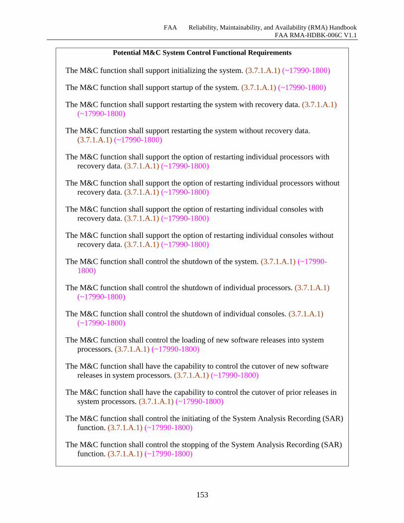
FAA Reliability, Maintainability, and Availability (RMA) Handbook
FAA RMA-HDBK-006C V1.1
153
Potential M&C System Control Functional Requirements
The M&C function shall support initializing the system. (3.7.1.A.1) (~17990-1800)
The M&C function shall support startup of the system. (3.7.1.A.1) (~17990-1800)
The M&C function shall support restarting the system with recovery data. (3.7.1.A.1)
(~17990-1800)
The M&C function shall support restarting the system without recovery data.
(3.7.1.A.1) (~17990-1800)
The M&C function shall support the option of restarting individual processors with
recovery data. (3.7.1.A.1) (~17990-1800)
The M&C function shall support the option of restarting individual processors without
recovery data. (3.7.1.A.1) (~17990-1800)
The M&C function shall support the option of restarting individual consoles with
recovery data. (3.7.1.A.1) (~17990-1800)
The M&C function shall support the option of restarting individual consoles without
recovery data. (3.7.1.A.1) (~17990-1800)
The M&C function shall control the shutdown of the system. (3.7.1.A.1) (~17990-
1800)
The M&C function shall control the shutdown of individual processors. (3.7.1.A.1)
(~17990-1800)
The M&C function shall control the shutdown of individual consoles. (3.7.1.A.1)
(~17990-1800)
The M&C function shall control the loading of new software releases into system
processors. (3.7.1.A.1) (~17990-1800)
The M&C function shall have the capability to control the cutover of new software
releases in system processors. (3.7.1.A.1) (~17990-1800)
The M&C function shall have the capability to control the cutover of prior releases in
system processors. (3.7.1.A.1) (~17990-1800)
The M&C function shall control the initiating of the System Analysis Recording (SAR)
function. (3.7.1.A.1) (~17990-1800)
The M&C function shall control the stopping of the System Analysis Recording (SAR)
function. (3.7.1.A.1) (~17990-1800)
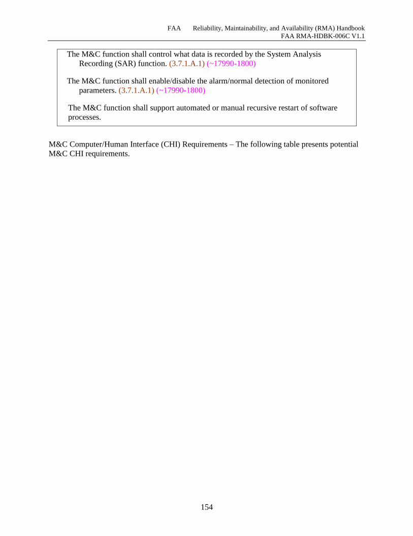
FAA Reliability, Maintainability, and Availability (RMA) Handbook
FAA RMA-HDBK-006C V1.1
154
The M&C function shall control what data is recorded by the System Analysis
Recording (SAR) function. (3.7.1.A.1) (~17990-1800)
The M&C function shall enable/disable the alarm/normal detection of monitored
parameters. (3.7.1.A.1) (~17990-1800)
The M&C function shall support automated or manual recursive restart of software
processes.
M&C Computer/Human Interface (CHI) Requirements – The following table presents potential
M&C CHI requirements.
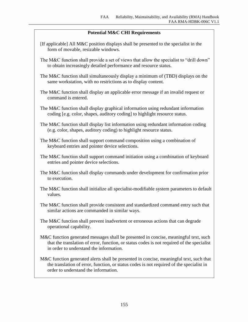
FAA Reliability, Maintainability, and Availability (RMA) Handbook
FAA RMA-HDBK-006C V1.1
155
Potential M&C CHI Requirements
[If applicable] All M&C position displays shall be presented to the specialist in the
form of movable, resizable windows.
The M&C function shall provide a set of views that allow the specialist to “drill down”
to obtain increasingly detailed performance and resource status.
The M&C function shall simultaneously display a minimum of (TBD) displays on the
same workstation, with no restrictions as to display content.
The M&C function shall display an applicable error message if an invalid request or
command is entered.
The M&C function shall display graphical information using redundant information
coding [e.g. color, shapes, auditory coding] to highlight resource status.
The M&C function shall display list information using redundant information coding
(e.g. color, shapes, auditory coding) to highlight resource status.
The M&C function shall support command composition using a combination of
keyboard entries and pointer device selections.
The M&C function shall support command initiation using a combination of keyboard
entries and pointer device selections.
The M&C function shall display commands under development for confirmation prior
to execution.
The M&C function shall initialize all specialist-modifiable system parameters to default
values.
The M&C function shall provide consistent and standardized command entry such that
similar actions are commanded in similar ways.
The M&C function shall prevent inadvertent or erroneous actions that can degrade
operational capability.
M&C function generated messages shall be presented in concise, meaningful text, such
that the translation of error, function, or status codes is not required of the specialist
in order to understand the information.
M&C function generated alerts shall be presented in concise, meaningful text, such that
the translation of error, function, or status codes is not required of the specialist in
order to understand the information.
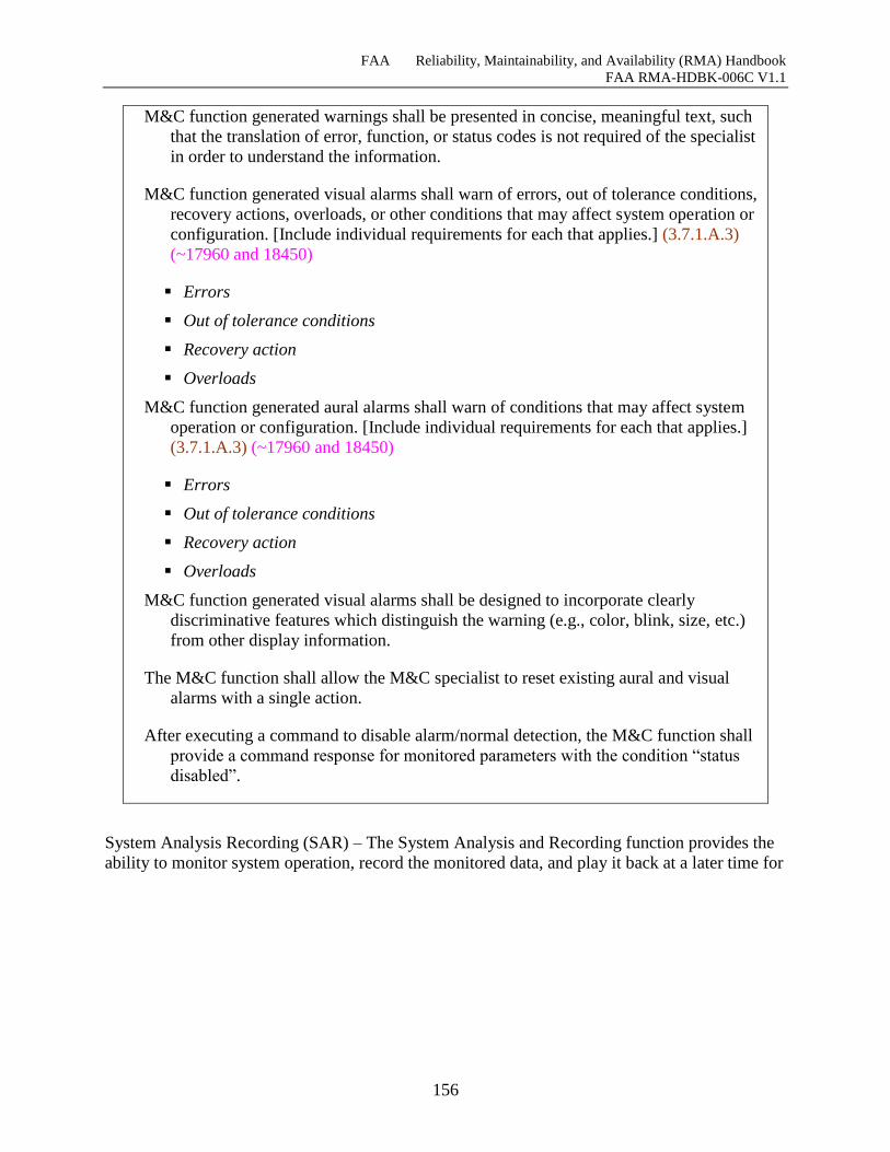
FAA Reliability, Maintainability, and Availability (RMA) Handbook
FAA RMA-HDBK-006C V1.1
156
M&C function generated warnings shall be presented in concise, meaningful text, such
that the translation of error, function, or status codes is not required of the specialist
in order to understand the information.
M&C function generated visual alarms shall warn of errors, out of tolerance conditions,
recovery actions, overloads, or other conditions that may affect system operation or
configuration. [Include individual requirements for each that applies.] (3.7.1.A.3)
(~17960 and 18450)
Errors
Out of tolerance conditions
Recovery action
Overloads
M&C function generated aural alarms shall warn of conditions that may affect system
operation or configuration. [Include individual requirements for each that applies.]
(3.7.1.A.3) (~17960 and 18450)
Errors
Out of tolerance conditions
Recovery action
Overloads
M&C function generated visual alarms shall be designed to incorporate clearly
discriminative features which distinguish the warning (e.g., color, blink, size, etc.)
from other display information.
The M&C function shall allow the M&C specialist to reset existing aural and visual
alarms with a single action.
After executing a command to disable alarm/normal detection, the M&C function shall
provide a command response for monitored parameters with the condition “status
disabled”.
System Analysis Recording (SAR) – The System Analysis and Recording function provides the
ability to monitor system operation, record the monitored data, and play it back at a later time for

FAA Reliability, Maintainability, and Availability (RMA) Handbook
FAA RMA-HDBK-006C V1.1
157
analysis. SAR data is used for incident and accident analysis, performance monitoring and
problem diagnosis. The following table presents potential SAR Functional requirements.
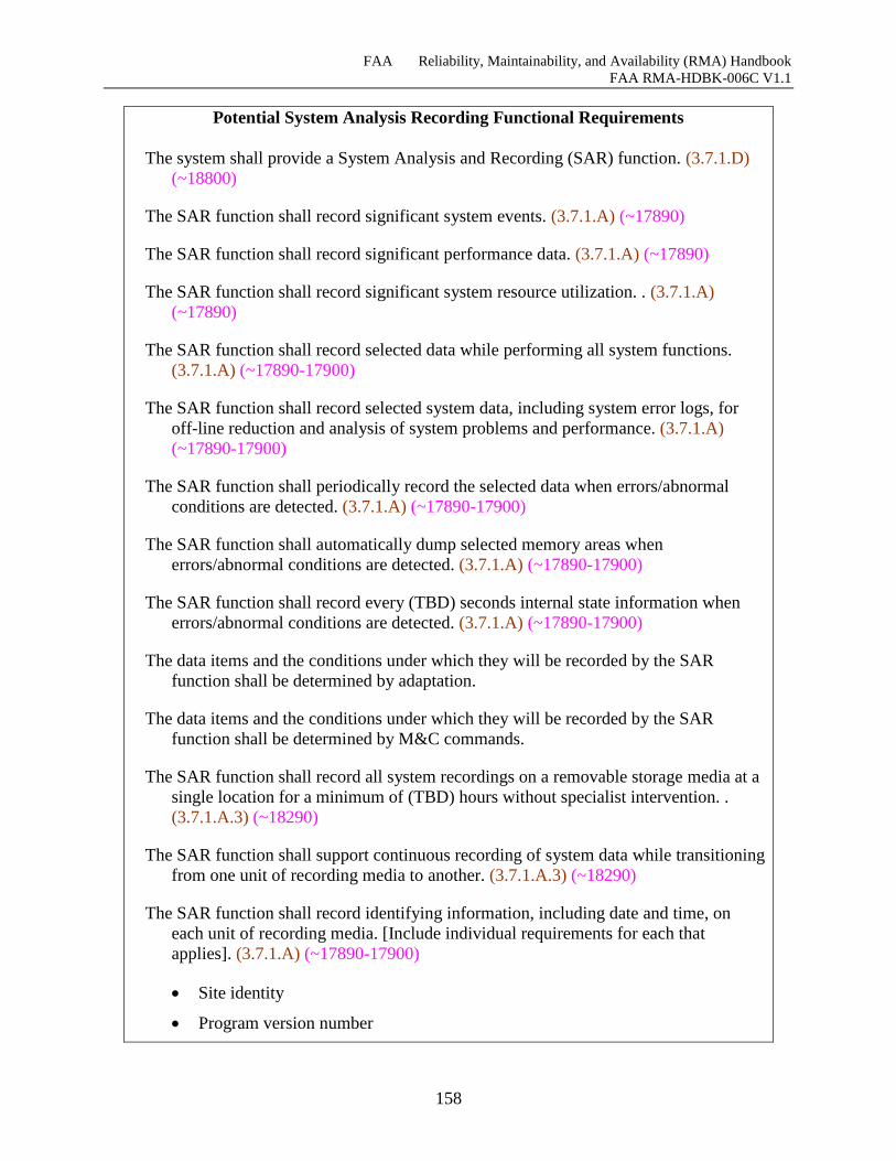
FAA Reliability, Maintainability, and Availability (RMA) Handbook
FAA RMA-HDBK-006C V1.1
158
Potential System Analysis Recording Functional Requirements
The system shall provide a System Analysis and Recording (SAR) function. (3.7.1.D)
(~18800)
The SAR function shall record significant system events. (3.7.1.A) (~17890)
The SAR function shall record significant performance data. (3.7.1.A) (~17890)
The SAR function shall record significant system resource utilization. . (3.7.1.A)
(~17890)
The SAR function shall record selected data while performing all system functions.
(3.7.1.A) (~17890-17900)
The SAR function shall record selected system data, including system error logs, for
off-line reduction and analysis of system problems and performance. (3.7.1.A)
(~17890-17900)
The SAR function shall periodically record the selected data when errors/abnormal
conditions are detected. (3.7.1.A) (~17890-17900)
The SAR function shall automatically dump selected memory areas when
errors/abnormal conditions are detected. (3.7.1.A) (~17890-17900)
The SAR function shall record every (TBD) seconds internal state information when
errors/abnormal conditions are detected. (3.7.1.A) (~17890-17900)
The data items and the conditions under which they will be recorded by the SAR
function shall be determined by adaptation.
The data items and the conditions under which they will be recorded by the SAR
function shall be determined by M&C commands.
The SAR function shall record all system recordings on a removable storage media at a
single location for a minimum of (TBD) hours without specialist intervention. .
(3.7.1.A.3) (~18290)
The SAR function shall support continuous recording of system data while transitioning
from one unit of recording media to another. (3.7.1.A.3) (~18290)
The SAR function shall record identifying information, including date and time, on
each unit of recording media. [Include individual requirements for each that
applies]. (3.7.1.A) (~17890-17900)
Site identity
Program version number
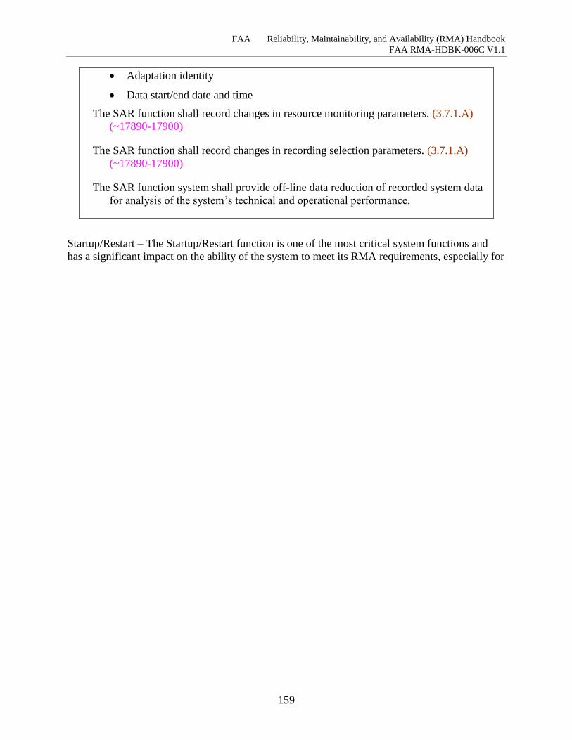
FAA Reliability, Maintainability, and Availability (RMA) Handbook
FAA RMA-HDBK-006C V1.1
159
Adaptation identity
Data start/end date and time
The SAR function shall record changes in resource monitoring parameters. (3.7.1.A)
(~17890-17900)
The SAR function shall record changes in recording selection parameters. (3.7.1.A)
(~17890-17900)
The SAR function system shall provide off-line data reduction of recorded system data
for analysis of the system’s technical and operational performance.
Startup/Restart – The Startup/Restart function is one of the most critical system functions and
has a significant impact on the ability of the system to meet its RMA requirements, especially for
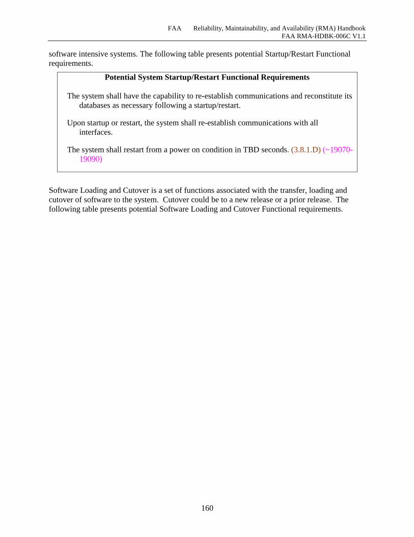
FAA Reliability, Maintainability, and Availability (RMA) Handbook
FAA RMA-HDBK-006C V1.1
160
software intensive systems. The following table presents potential Startup/Restart Functional
requirements.
Potential System Startup/Restart Functional Requirements
The system shall have the capability to re-establish communications and reconstitute its
databases as necessary following a startup/restart.
Upon startup or restart, the system shall re-establish communications with all
interfaces.
The system shall restart from a power on condition in TBD seconds. (3.8.1.D) (~19070-
19090)
Software Loading and Cutover is a set of functions associated with the transfer, loading and
cutover of software to the system. Cutover could be to a new release or a prior release. The
following table presents potential Software Loading and Cutover Functional requirements.
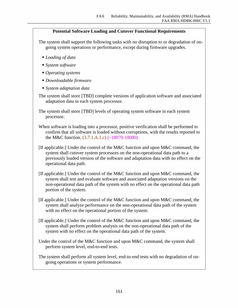
FAA Reliability, Maintainability, and Availability (RMA) Handbook
FAA RMA-HDBK-006C V1.1
161
Potential Software Loading and Cutover Functional Requirements
The system shall support the following tasks with no disruption to or degradation of on-
going system operations or performance, except during firmware upgrades.
Loading of data
System software
Operating systems
Downloadable firmware
System adaptation data
The system shall store [TBD] complete versions of application software and associated
adaptation data in each system processor.
The system shall store [TBD] levels of operating system software in each system
processor.
When software is loading into a processor, positive verification shall be performed to
confirm that all software is loaded without corruptions, with the results reported to
the M&C function. (3.7.1.A.1.c) (~18070-18080)
[If applicable.] Under the control of the M&C function and upon M&C command, the
system shall cutover system processors on the non-operational data path to a
previously loaded version of the software and adaptation data with no effect on the
operational data path.
[If applicable.] Under the control of the M&C function and upon M&C command, the
system shall test and evaluate software and associated adaptation versions on the
non-operational data path of the system with no effect on the operational data path
portion of the system.
[If applicable.] Under the control of the M&C function and upon M&C command, the
system shall analyze performance on the non-operational data path of the system
with no effect on the operational portion of the system.
[If applicable.] Under the control of the M&C function and upon M&C command, the
system shall perform problem analysis on the non-operational data path of the
system with no effect on the operational data path of the system.
Under the control of the M&C function and upon M&C command, the system shall
perform system level, end-to-end tests.
The system shall perform all system level, end-to-end tests with no degradation of on-
going operations or system performance.
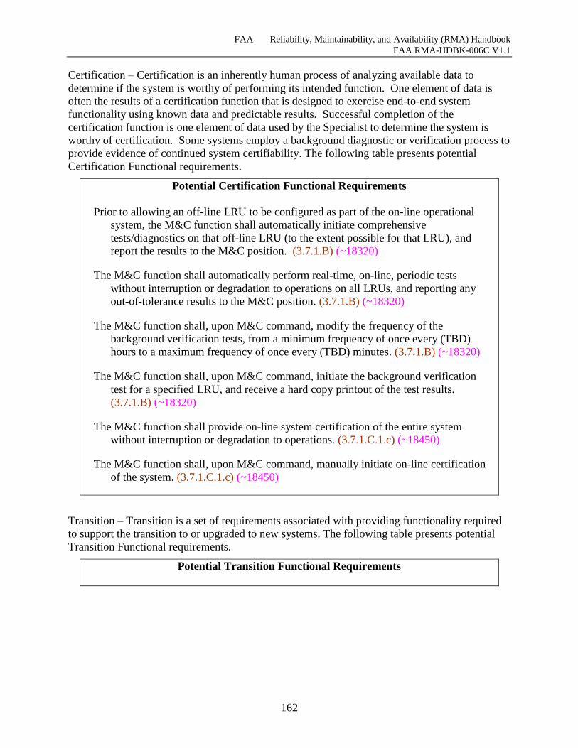
FAA Reliability, Maintainability, and Availability (RMA) Handbook
FAA RMA-HDBK-006C V1.1
162
Certification – Certification is an inherently human process of analyzing available data to
determine if the system is worthy of performing its intended function. One element of data is
often the results of a certification function that is designed to exercise end-to-end system
functionality using known data and predictable results. Successful completion of the
certification function is one element of data used by the Specialist to determine the system is
worthy of certification. Some systems employ a background diagnostic or verification process to
provide evidence of continued system certifiability. The following table presents potential
Certification Functional requirements.
Potential Certification Functional Requirements
Prior to allowing an off-line LRU to be configured as part of the on-line operational
system, the M&C function shall automatically initiate comprehensive
tests/diagnostics on that off-line LRU (to the extent possible for that LRU), and
report the results to the M&C position. (3.7.1.B) (~18320)
The M&C function shall automatically perform real-time, on-line, periodic tests
without interruption or degradation to operations on all LRUs, and reporting any
out-of-tolerance results to the M&C position. (3.7.1.B) (~18320)
The M&C function shall, upon M&C command, modify the frequency of the
background verification tests, from a minimum frequency of once every (TBD)
hours to a maximum frequency of once every (TBD) minutes. (3.7.1.B) (~18320)
The M&C function shall, upon M&C command, initiate the background verification
test for a specified LRU, and receive a hard copy printout of the test results.
(3.7.1.B) (~18320)
The M&C function shall provide on-line system certification of the entire system
without interruption or degradation to operations. (3.7.1.C.1.c) (~18450)
The M&C function shall, upon M&C command, manually initiate on-line certification
of the system. (3.7.1.C.1.c) (~18450)
Transition – Transition is a set of requirements associated with providing functionality required
to support the transition to or upgraded to new systems. The following table presents potential
Transition Functional requirements.
Potential Transition Functional Requirements
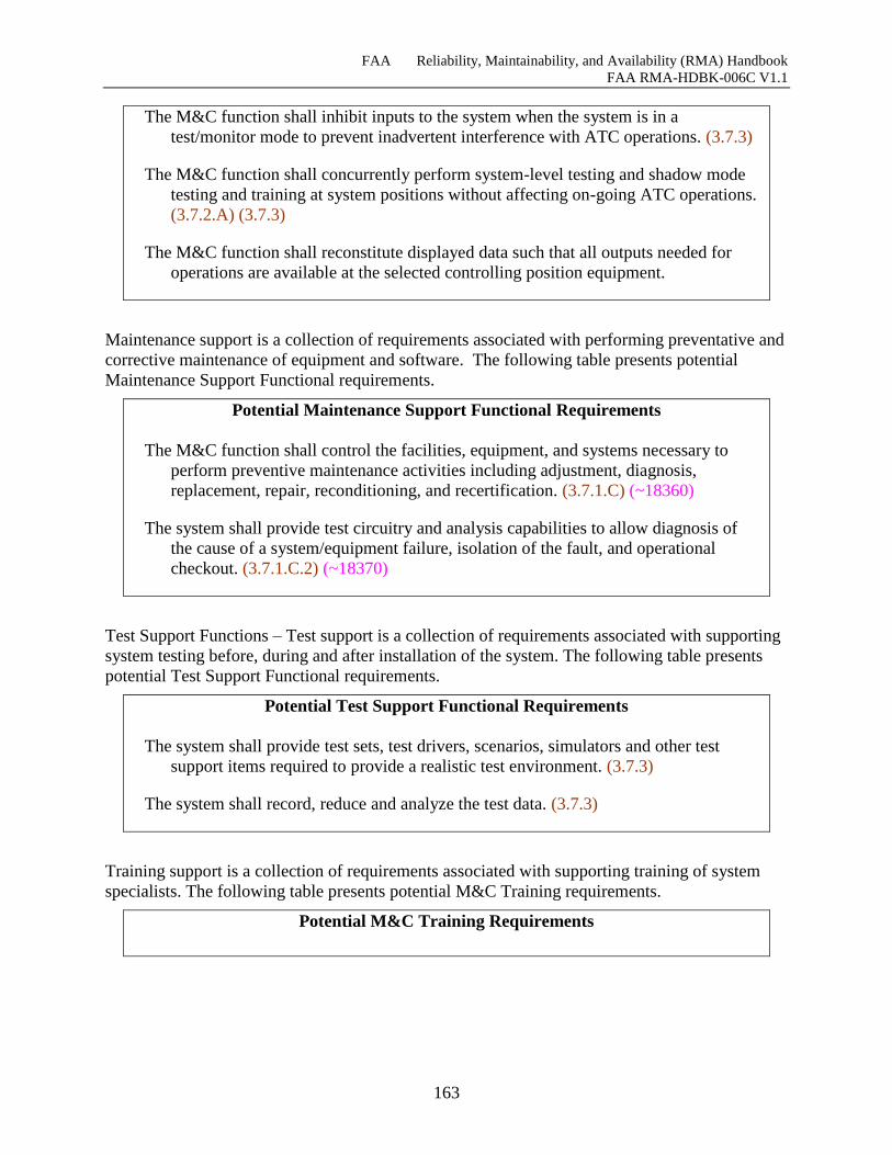
FAA Reliability, Maintainability, and Availability (RMA) Handbook
FAA RMA-HDBK-006C V1.1
163
The M&C function shall inhibit inputs to the system when the system is in a
test/monitor mode to prevent inadvertent interference with ATC operations. (3.7.3)
The M&C function shall concurrently perform system-level testing and shadow mode
testing and training at system positions without affecting on-going ATC operations.
(3.7.2.A) (3.7.3)
The M&C function shall reconstitute displayed data such that all outputs needed for
operations are available at the selected controlling position equipment.
Maintenance support is a collection of requirements associated with performing preventative and
corrective maintenance of equipment and software. The following table presents potential
Maintenance Support Functional requirements.
Potential Maintenance Support Functional Requirements
The M&C function shall control the facilities, equipment, and systems necessary to
perform preventive maintenance activities including adjustment, diagnosis,
replacement, repair, reconditioning, and recertification. (3.7.1.C) (~18360)
The system shall provide test circuitry and analysis capabilities to allow diagnosis of
the cause of a system/equipment failure, isolation of the fault, and operational
checkout. (3.7.1.C.2) (~18370)
Test Support Functions – Test support is a collection of requirements associated with supporting
system testing before, during and after installation of the system. The following table presents
potential Test Support Functional requirements.
Potential Test Support Functional Requirements
The system shall provide test sets, test drivers, scenarios, simulators and other test
support items required to provide a realistic test environment. (3.7.3)
The system shall record, reduce and analyze the test data. (3.7.3)
Training support is a collection of requirements associated with supporting training of system
specialists. The following table presents potential M&C Training requirements.
Potential M&C Training Requirements
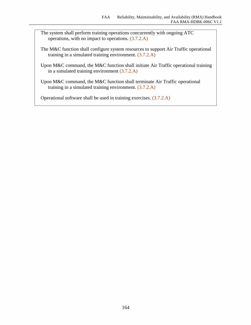
FAA Reliability, Maintainability, and Availability (RMA) Handbook
FAA RMA-HDBK-006C V1.1
164
The system shall perform training operations concurrently with ongoing ATC
operations, with no impact to operations. (3.7.2.A)
The M&C function shall configure system resources to support Air Traffic operational
training in a simulated training environment. (3.7.2.A)
Upon M&C command, the M&C function shall initiate Air Traffic operational training
in a simulated training environment (3.7.2.A)
Upon M&C command, the M&C function shall terminate Air Traffic operational
training in a simulated training environment. (3.7.2.A)
Operational software shall be used in training exercises. (3.7.2.A)
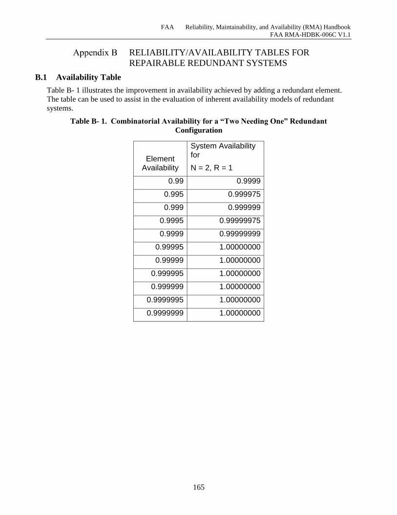
FAA Reliability, Maintainability, and Availability (RMA) Handbook
FAA RMA-HDBK-006C V1.1
165
RELIABILITY/AVAILABILITY TABLES FOR
REPAIRABLE REDUNDANT SYSTEMS
B.1 Availability Table
Table B- 1 illustrates the improvement in availability achieved by adding a redundant element.
The table can be used to assist in the evaluation of inherent availability models of redundant
systems.
Table B- 1. Combinatorial Availability for a “Two Needing One” Redundant
Configuration
Element Availability
System Availability for
N = 2, R = 1
0.99 0.9999
0.995 0.999975
0.999 0.999999
0.9995 0.99999975
0.9999 0.99999999
0.99995 1.00000000
0.99999 1.00000000
0.999995 1.00000000
0.999999 1.00000000
0.9999995 1.00000000
0.9999999 1.00000000
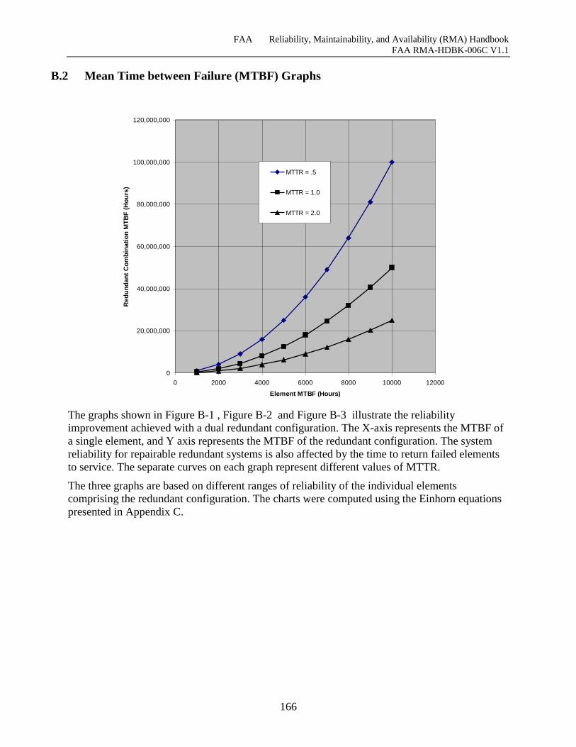
FAA Reliability, Maintainability, and Availability (RMA) Handbook
FAA RMA-HDBK-006C V1.1
166
B.2 Mean Time between Failure (MTBF) Graphs
The graphs shown in Figure B-1 , Figure B-2 and Figure B-3 illustrate the reliability
improvement achieved with a dual redundant configuration. The X-axis represents the MTBF of
a single element, and Y axis represents the MTBF of the redundant configuration. The system
reliability for repairable redundant systems is also affected by the time to return failed elements
to service. The separate curves on each graph represent different values of MTTR.
The three graphs are based on different ranges of reliability of the individual elements
comprising the redundant configuration. The charts were computed using the Einhorn equations
presented in Appendix C.
0
20,000,000
40,000,000
60,000,000
80,000,000
100,000,000
120,000,000
0 2000 4000 6000 8000 10000 12000
Element MTBF (Hours)
Re
du
nd
an
t C
om
bin
ati
on
MT
BF
(H
ou
rs)
MTTR = .5
MTTR = 1.0
MTTR = 2.0
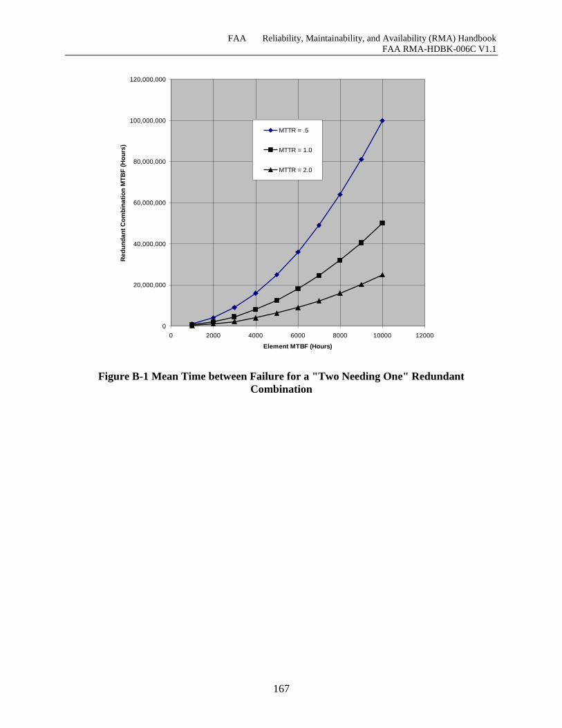
FAA Reliability, Maintainability, and Availability (RMA) Handbook
FAA RMA-HDBK-006C V1.1
167
Figure B-1 Mean Time between Failure for a "Two Needing One" Redundant
Combination
0
20,000,000
40,000,000
60,000,000
80,000,000
100,000,000
120,000,000
0 2000 4000 6000 8000 10000 12000
Element MTBF (Hours)
Re
du
nd
an
t C
om
bin
ati
on
MT
BF
(H
ou
rs)
MTTR = .5
MTTR = 1.0
MTTR = 2.0
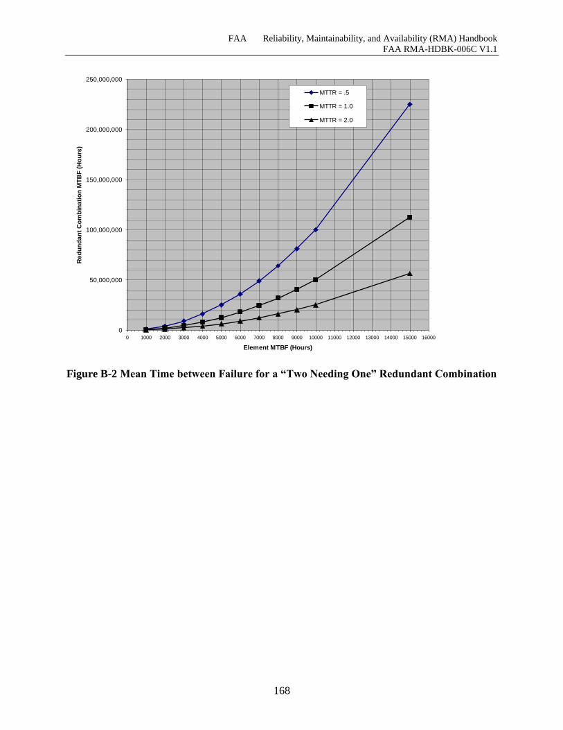
FAA Reliability, Maintainability, and Availability (RMA) Handbook
FAA RMA-HDBK-006C V1.1
168
Figure B-2 Mean Time between Failure for a “Two Needing One” Redundant Combination
0
50,000,000
100,000,000
150,000,000
200,000,000
250,000,000
0 1000 2000 3000 4000 5000 6000 7000 8000 9000 10000 11000 12000 13000 14000 15000 16000
Element MTBF (Hours)
Re
du
nd
an
t C
om
bin
ati
on
MT
BF
(H
ou
rs)
MTTR = .5
MTTR = 1.0
MTTR = 2.0
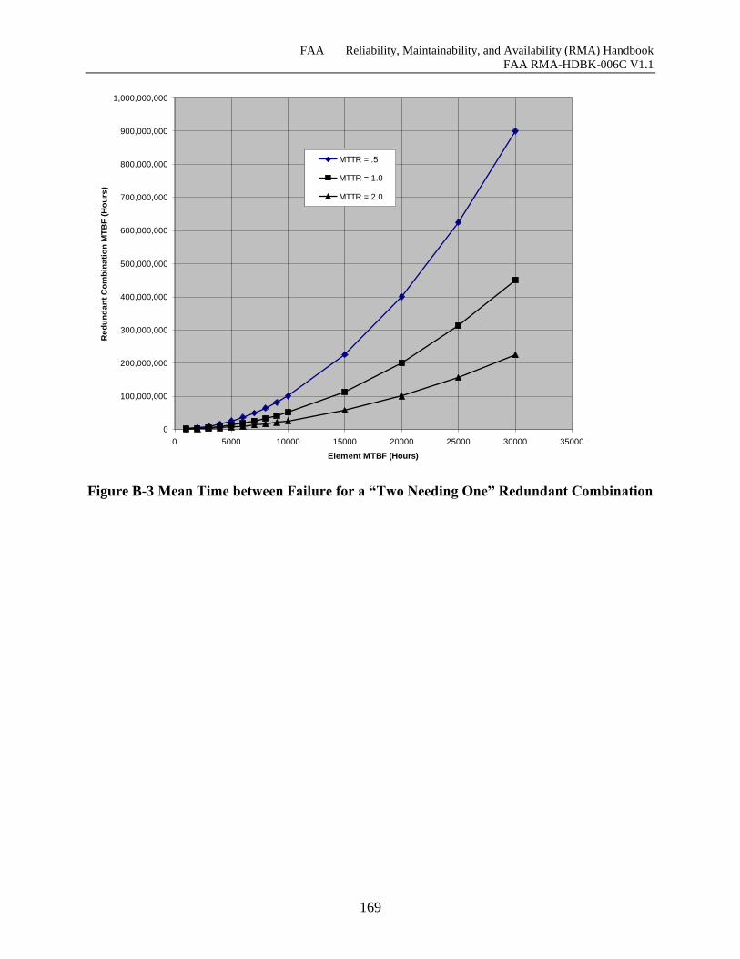
FAA Reliability, Maintainability, and Availability (RMA) Handbook
FAA RMA-HDBK-006C V1.1
169
Figure B-3 Mean Time between Failure for a “Two Needing One” Redundant Combination
0
100,000,000
200,000,000
300,000,000
400,000,000
500,000,000
600,000,000
700,000,000
800,000,000
900,000,000
1,000,000,000
0 5000 10000 15000 20000 25000 30000 35000
Element MTBF (Hours)
Re
du
nd
an
t C
om
bin
ati
on
MT
BF
(H
ou
rs)
MTTR = .5
MTTR = 1.0
MTTR = 2.0
FAA Reliability, Maintainability, and Availability (RMA) Handbook
FAA RMA-HDBK-006C V1.1
170
STATISTICAL METHODS AND LIMITATIONS
C.1 Reliability Modeling and Prediction
The statistical basis for reliability modeling was originally developed in the 1950’s when
electronic equipment was fabricated with discreet components such as capacitors, resistors, and
transistors. The overall reliability of electronic equipment is related to the numbers and failure
rates of the individual components used in the equipment. Two fundamental assumptions form
the basis for conventional parts count reliability models:
The failure rates of components are assumed to be constant. (After a short initial
burn-in interval and before end-of-life wear out—the “bathtub curve.”)
The failures of individual components occur independently of one another.
The constant failure rate assumption allows the use of an exponential distribution to describe the
distribution of time to failure, so that the probability a component will survive for time t is given
by
[C-1]
(Where R is the survival probability, is the constant failure rate, and t is the time.)
The assumption of independent failures means that the failure of one component does not affect
the probability of failure of another component. Hence the probability of all components
surviving is the product of the individual survival probabilities.
[C-2]
Because of the exponential distribution of failures, the total failure rate is simply the sum of the
individual failure rates and the total reliability is
[C-3]
Where T is given by
[C-4]
The equation for predicting the equipment failure rate using the parts count method is given by
MIL-HDBK-217 as
[C-5]
teR
nT RRRR 21
t
TTeR
n
i
iT
1
n
i
QGiEquip N1
)(
FAA Reliability, Maintainability, and Availability (RMA) Handbook
FAA RMA-HDBK-006C V1.1
171
Where
EQUIP = Total equipment failure rate (failures/106 hours)
G = Generic failure rate for the ith generic part (failures/106 hours)
Q = Quality factor for the ith generic part
Ni = Quantity of ith generic part
N = Number of different generic part categories in the equipment
This reliability prediction technique worked reasonably well for simple “black box” electronic
equipment. However, the introduction of fault-tolerant redundant computer systems created a
need for more complex modeling techniques that are discussed in Section C.5.
C.2 Maintainability
Maintainability is defined in MIL-STD-721Rev C as: “The measure of the ability of an item to
be retained in or restored to specified condition when maintenance is performed by personnel
having specified skill levels, using prescribed procedures and resources, at each prescribed level
of maintenance and repair.”
Maintainability prediction methods depend primarily on two basic parameters, the failure rates of
components at the level of maintenance actions, and the repair or replacement time for the
components. Historically, maintainability predictions for electronic equipment involved a
detailed examination of the components’ failure rates and the measured time required for
diagnosing and replacing or repairing each of the failed components. A statistical model
combined the failure rates and repair times of the equipment’s components to determine an
overall MTTR or MDT.
Maintainability was a design characteristic of the equipment. Repair times were affected by the
quality of built in test equipment (BITE), diagnostic tools, and the ease of access, removal, and
replacement of failed components.
With the advent of redundant, fault-tolerant systems, in which restoration of service is performed
by automatic switchover and corrective maintenance is performed off-line, maintainability is not
as significant as it once was. In addition, the move to utilizing more commercial off the shelf
(COTS) equipment that is simply removed and replaced has made the traditional maintainability
calculations as expressed in MIL-HDBK-472 less relevant.
C.3 Availability
Availability is defined in MIL-STD-721 as a measure of the degree to which an item is in an
operable and Committable State at the start of a mission when the mission is called for at an
unknown (random) time. As such, availability is the probability that the system will be available
when needed, and the availabilities for independent subsystems can be combined by simply
multiplying the availabilities. (Availability is also used to express the percentage of units that
may be available at the start of a mission, e.g. how many aircraft in a squadron will be available
at the start of a mission.)
FAA Reliability, Maintainability, and Availability (RMA) Handbook
FAA RMA-HDBK-006C V1.1
172
Availability is measured in the field by subtracting the downtime from the total elapsed time to
obtain the time that the system was operational and dividing this time by the total elapsed time.
Operational availability includes all downtime. Other availability measures have been defined
that exclude various categories of downtime such as those caused by administrative delays and
logistics supply problems. The purpose of these other measures of availability is to develop
metrics that more accurately reflect the characteristics of the system itself removing downtime
that is attributable to deficiencies in the human administration of the system.
Availability is usually not predicted directly, but is usually derived from both the failure and
repair characteristics of the equipment. Availability is expressed as:
[C-6]
Where MTBF is the Mean Time between Failures and MTTR is the mean time to repair, or
equivalently, Availability can also be expressed as:
[C-7]
(Where MUT is the Mean Up Time and MDT is the Mean Downtime.)
As discussed earlier, availability allows reliability and maintainability to be traded off. Although
this practice may be acceptable for equipment where optimizing life cycle costs is the primary
consideration, it is may not be appropriate for systems that provide critical services to air traffic
controllers, where lengthy service interruptions may be unacceptable, regardless of how
infrequently they are predicted to occur.
C.4 Modeling Repairable Redundant Systems
The increasing use of digital computers for important real-time and near-real-time operations in
the 1960’s created a demand for systems with much greater reliability than that which could be
achieved with the current state of the art for electronic systems constructed with large numbers
of discrete components. For example, the IBM 360 series computers employed in NAS Stage A
had a MTBF on the order of 1000 hours. The path to higher reliability systems was to employ
redundancy and automatic fault detection and recovery. The introduction of repairable
redundant systems required new methods for predicting the reliability of these systems. One of
the first attempts at predicting the reliability of these systems was presented in a paper by S. J.
Einhorn in 1963. He developed a method for predicting the reliability of a repairable redundant
system using the mean time to failure and mean time to repair for the elements of the system. He
assumed that the system elements conformed to the exponential failure and repair time
distributions and that the failure and repair behaviors of the elements are independent of one
another. The Einhorn equation for predicting the reliability of an r out of n redundant system is
presented below.
[C-8]
MTTRMTBF
MTBFA
MDTMUT
MUTA
rnr
jnjn
rj
DUr
nn
DUj
n
MUT
1
1
1
FAA Reliability, Maintainability, and Availability (RMA) Handbook
FAA RMA-HDBK-006C V1.1
173
Where MUT is the mean UP time, n is the total number of elements in a subsystem, r is the
number of elements that are required for the system to be UP, and the number of combinations of
n things taken r at a time is given by
[C-9]
The Einhorn method provided a relatively simple way to predict the combinatorial reliability of
an “r out of n” repairable redundant configuration of identical elements. This method assumes
perfect fault detection, isolation and recovery and does not account for switchover failures or
allow for degraded modes of operation.
In order to incorporate these additional factors, Markov models were developed to model
reliability and availability. Typically, Markov models of redundant systems assume that the
overall system is organized as a set of distinct subsystems, where each subsystem is composed of
identical elements and the failure of a subsystem is independent of the status of the other
subsystems. In each of the subsystems, redundancy is modeled by a Markov process with the
following typical assumptions:
Failure rates and repair rates are constants.
System crashes resulting from the inability to recover from some failures even though
operational spares are available are modeled by means of “coverage” parameters.
(Coverage is defined as the probability that the system can recover, given that a fault
has occurred.)
For recoverable failures, the recovery process is instantaneous if useable spares are
available.
Spare failures are detected immediately.
As soon as a failed unit is repaired, it is assumed to be in perfect condition and is
returned to the pool of spares.
Reliability analysis using Markov models follows four distinct steps:
1. Development of the state transition diagram
2. Mathematical representation (Differential equation setup)
3. Solution of the differential equations
4. Calculation of the reliability measures
An example of a general state transition diagram for a system with three states is provided Figure
C-1 . The circles represent the possible states of the system and the arcs represent the transitions
between the states. A three-state model is used to represent the behavior of a simple system with
two elements, one of which must be operational for the system to be up. In State 1, both elements
are operational. In State 2, one of the elements has failed, but the system is still operational. In
State 3, both elements have failed and the system is down.
)!(!
!
!
)1()2)(1(
rnr
n
r
rnnnn
r
n
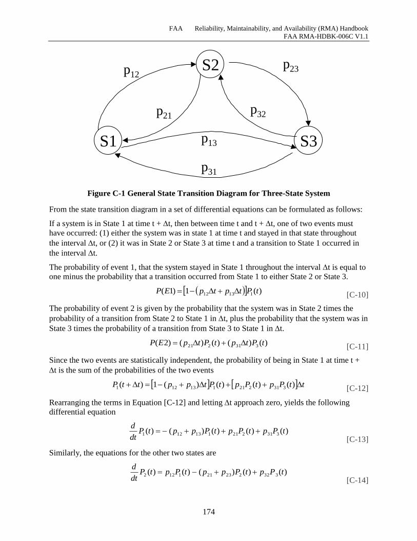
FAA Reliability, Maintainability, and Availability (RMA) Handbook
FAA RMA-HDBK-006C V1.1
174
Figure C-1 General State Transition Diagram for Three-State System
From the state transition diagram in a set of differential equations can be formulated as follows:
If a system is in State 1 at time t + t, then between time t and t + t, one of two events must
have occurred: (1) either the system was in state 1 at time t and stayed in that state throughout
the interval t, or (2) it was in State 2 or State 3 at time t and a transition to State 1 occurred in
the interval t.
The probability of event 1, that the system stayed in State 1 throughout the interval t is equal to
one minus the probability that a transition occurred from State 1 to either State 2 or State 3.
[C-10]
The probability of event 2 is given by the probability that the system was in State 2 times the
probability of a transition from State 2 to State 1 in t, plus the probability that the system was in
State 3 times the probability of a transition from State 3 to State 1 in t.
[C-11]
Since the two events are statistically independent, the probability of being in State 1 at time t +
t is the sum of the probabilities of the two events
[C-12]
Rearranging the terms in Equation [C-12] and letting t approach zero, yields the following
differential equation
[C-13]
Similarly, the equations for the other two states are
[C-14]
S1
S2
S3
p12p23
p21p32
p13
p31
)(1)1( 11312 tPtptpEP
)()()()()2( 331221 tPtptPtpEP
ttPptPptPtppttP )()()()(1)( 331221113121
)()()()()( 331221113121 tPptPptPpptPdt
d
)()()()()( 332223211122 tPptPpptPptPdt
d
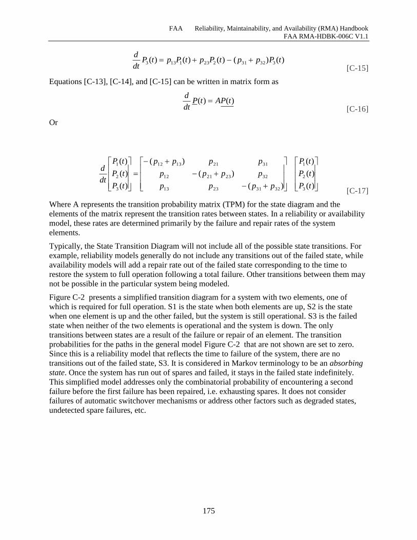
FAA Reliability, Maintainability, and Availability (RMA) Handbook
FAA RMA-HDBK-006C V1.1
175
[C-15]
Equations [C-13], [C-14], and [C-15] can be written in matrix form as
[C-16]
Or
[C-17]
Where A represents the transition probability matrix (TPM) for the state diagram and the
elements of the matrix represent the transition rates between states. In a reliability or availability
model, these rates are determined primarily by the failure and repair rates of the system
elements.
Typically, the State Transition Diagram will not include all of the possible state transitions. For
example, reliability models generally do not include any transitions out of the failed state, while
availability models will add a repair rate out of the failed state corresponding to the time to
restore the system to full operation following a total failure. Other transitions between them may
not be possible in the particular system being modeled.
Figure C-2 presents a simplified transition diagram for a system with two elements, one of
which is required for full operation. S1 is the state when both elements are up, S2 is the state
when one element is up and the other failed, but the system is still operational. S3 is the failed
state when neither of the two elements is operational and the system is down. The only
transitions between states are a result of the failure or repair of an element. The transition
probabilities for the paths in the general model Figure C-2 that are not shown are set to zero.
Since this is a reliability model that reflects the time to failure of the system, there are no
transitions out of the failed state, S3. It is considered in Markov terminology to be an absorbing
state. Once the system has run out of spares and failed, it stays in the failed state indefinitely.
This simplified model addresses only the combinatorial probability of encountering a second
failure before the first failure has been repaired, i.e. exhausting spares. It does not consider
failures of automatic switchover mechanisms or address other factors such as degraded states,
undetected spare failures, etc.
)()()()()( 332312231133 tPpptPptPptPdt
d
)()( tPAtPdt
d
)(
)(
)(
)(
)(
)(
)(
)(
)(
3
2
1
32312313
32232112
31211312
3
2
1
tP
tP
tP
pppp
pppp
pppp
tP
tP
tP
dt
d
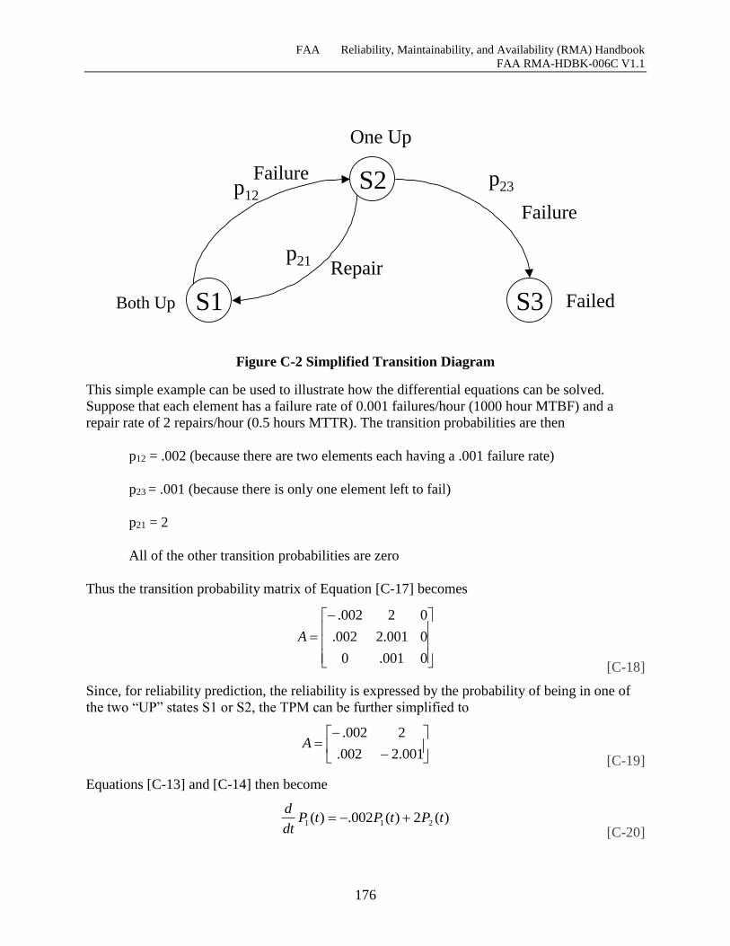
FAA Reliability, Maintainability, and Availability (RMA) Handbook
FAA RMA-HDBK-006C V1.1
176
Figure C-2 Simplified Transition Diagram
This simple example can be used to illustrate how the differential equations can be solved.
Suppose that each element has a failure rate of 0.001 failures/hour (1000 hour MTBF) and a
repair rate of 2 repairs/hour (0.5 hours MTTR). The transition probabilities are then
p12 = .002 (because there are two elements each having a .001 failure rate)
p23 = .001 (because there is only one element left to fail)
p21 = 2
All of the other transition probabilities are zero
Thus the transition probability matrix of Equation [C-17] becomes
[C-18]
Since, for reliability prediction, the reliability is expressed by the probability of being in one of
the two “UP” states S1 or S2, the TPM can be further simplified to
[C-19]
Equations [C-13] and [C-14] then become
[C-20]
0001.0
0001.2002.
02002.
A
001.2002.
2002.A
)(2)(002.)( 211 tPtPtPdt
d
S1
S2
S3
p12p23
p21
One Up
Both Up Failed
Repair
Failure
Failure
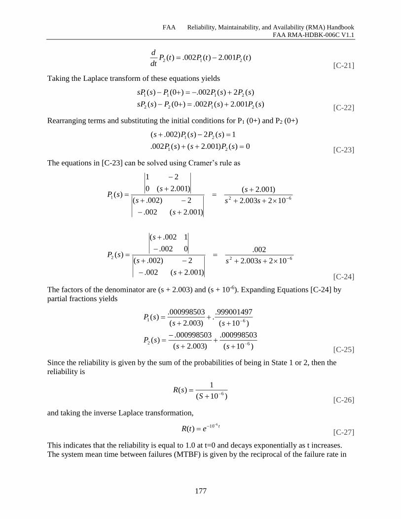
FAA Reliability, Maintainability, and Availability (RMA) Handbook
FAA RMA-HDBK-006C V1.1
177
[C-21]
Taking the Laplace transform of these equations yields
[C-22]
Rearranging terms and substituting the initial conditions for P1 (0+) and P2 (0+)
[C-23]
The equations in [C-23] can be solved using Cramer’s rule as
[C-24]
The factors of the denominator are (s + 2.003) and (s + 10-6). Expanding Equations [C-24] by
partial fractions yields
[C-25]
Since the reliability is given by the sum of the probabilities of being in State 1 or 2, then the
reliability is
[C-26]
and taking the inverse Laplace transformation,
[C-27]
This indicates that the reliability is equal to 1.0 at t=0 and decays exponentially as t increases.
The system mean time between failures (MTBF) is given by the reciprocal of the failure rate in
)(001.2)(002.)( 212 tPtPtPdt
d
)(001.2)(002.)0()(
)(2)(002.)0()(
2122
2111
sPsPPssP
sPsPPssP
0)()001.2()(002.
1)(2)()002.(
21
21
sPssP
sPsPs
622
621
102003.2
002.
)001.2(002.
2)002.(
0002.
1002.(
)(
102003.2
)001.2(
)001.2(002.
2)002.(
)001.2(0
21
)(
ss
s
s
s
sP
ss
s
s
s
ssP
)10(
000998503.
)003.2(
000998503.)(
)10(
999001497..
)003.2(
000998503.)(
62
61
sssP
sssP
)10(
1)(
6
SsR
tetR610)(
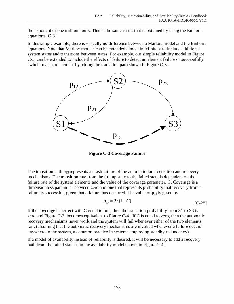
FAA Reliability, Maintainability, and Availability (RMA) Handbook
FAA RMA-HDBK-006C V1.1
178
the exponent or one million hours. This is the same result that is obtained by using the Einhorn
equations [C-8]
In this simple example, there is virtually no difference between a Markov model and the Einhorn
equations. Note that Markov models can be extended almost indefinitely to include additional
system states and transitions between states. For example, our simple reliability model in Figure
C-3 can be extended to include the effects of failure to detect an element failure or successfully
switch to a spare element by adding the transition path shown in Figure C-3 .
Figure C-3 Coverage Failure
The transition path p13 represents a crash failure of the automatic fault detection and recovery
mechanisms. The transition rate from the full up state to the failed state is dependent on the
failure rate of the system elements and the value of the coverage parameter, C. Coverage is a
dimensionless parameter between zero and one that represents probability that recovery from a
failure is successful, given that a failure has occurred. The value of p13 is given by
[C-28]
If the coverage is perfect with C equal to one, then the transition probability from S1 to S3 is
zero and Figure C-3 becomes equivalent to Figure C-4 . If C is equal to zero, then the automatic
recovery mechanisms never work and the system will fail whenever either of the two elements
fail, (assuming that the automatic recovery mechanisms are invoked whenever a failure occurs
anywhere in the system, a common practice in systems employing standby redundancy).
If a model of availability instead of reliability is desired, it will be necessary to add a recovery
path from the failed state as in the availability model shown in Figure C-4 .
S1
S2
S3
p12p23
p21
p13
)1(213 Cp
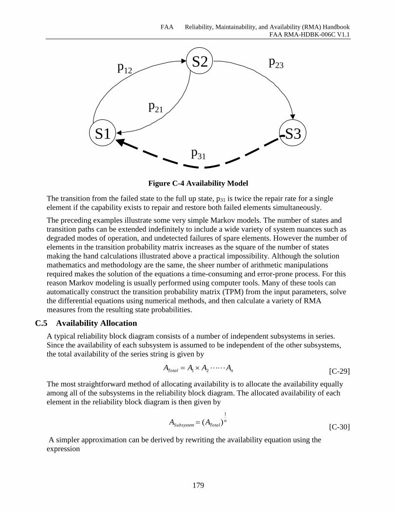
FAA Reliability, Maintainability, and Availability (RMA) Handbook
FAA RMA-HDBK-006C V1.1
179
Figure C-4 Availability Model
The transition from the failed state to the full up state, p31 is twice the repair rate for a single
element if the capability exists to repair and restore both failed elements simultaneously.
The preceding examples illustrate some very simple Markov models. The number of states and
transition paths can be extended indefinitely to include a wide variety of system nuances such as
degraded modes of operation, and undetected failures of spare elements. However the number of
elements in the transition probability matrix increases as the square of the number of states
making the hand calculations illustrated above a practical impossibility. Although the solution
mathematics and methodology are the same, the sheer number of arithmetic manipulations
required makes the solution of the equations a time-consuming and error-prone process. For this
reason Markov modeling is usually performed using computer tools. Many of these tools can
automatically construct the transition probability matrix (TPM) from the input parameters, solve
the differential equations using numerical methods, and then calculate a variety of RMA
measures from the resulting state probabilities.
C.5 Availability Allocation
A typical reliability block diagram consists of a number of independent subsystems in series.
Since the availability of each subsystem is assumed to be independent of the other subsystems,
the total availability of the series string is given by
[C-29]
The most straightforward method of allocating availability is to allocate the availability equally
among all of the subsystems in the reliability block diagram. The allocated availability of each
element in the reliability block diagram is then given by
[C-30]
A simpler approximation can be derived by rewriting the availability equation using the
expression
S1
S2
S3
p12p23
p21
p31
nTotal AAAA 21
nTotalSubsystem AA
1
)(
FAA Reliability, Maintainability, and Availability (RMA) Handbook
FAA RMA-HDBK-006C V1.1
180
[C-31]
where A represents the unavailability. Rewriting equation [C-29]
[C-32]
Multiplying terms and discarding higher order unavailability products yields the following
approximation
[C-33]
or by rearranging terms
[C-34]
The approximation given by Equation [C-34] allows the availability allocation to be performed
by simple division instead of calculating the nth root of the total availability as in Equation
[C-30].
Thus to allocate availability equally across n independent subsystems, it is only necessary to
divide the total unavailability by the number of subsystems in the series string to determine the
allocated unavailability for each subsystem. The allocated availability for each subsystem then is
simply
[C-35]
At this point, it is instructive to reflect on where all of this mathematics is leading. Looking at
equation [C-35] if n = 10, the allocated availability required for each subsystem in the string will
be an order of magnitude greater than the total availability of the service thread. This
relationship holds for any value of total availability. For a service thread with ten subsystems, the
allocated availability for each subsystem in a service thread will always be one “nine” greater
than the number of “nines” required for the total availability of the service thread. Since none of
the current threads has ten subsystems, all availability allocations will be less than an order of
magnitude greater than the total availability required by the service thread. By simply requiring
the availability of any system in a thread to be an order of magnitude greater than the end-to-end
availability of the thread, the end-to-end availability of the thread will be ensured unless there are
more than 10 systems in the thread. This convention eliminates the requirement to perform a
mathematical allocation and eliminates the issue of whether the NAS-Level availability should
be equally allocated across all systems in the thread. Mathematical allocations also contribute to
the illusion of false precision. It is likely that allocations will be rounded up to an even number
of “nines” anyway. The risk, of course, of requiring that systems have availability an order of
magnitude greater that the threads they support is that the system availability requirement is
greater than absolutely necessary, and could conceivably cause systems to be more costly.
)1( AA
)1()1()1( 21 nTotal AAAA
)1( SubsystemTotal AnA
TotalSubsystem An
A 1
n
AA
Total
Subsystem 1
FAA Reliability, Maintainability, and Availability (RMA) Handbook
FAA RMA-HDBK-006C V1.1
181
This should not be a problem for two reasons. First, as discussed in Section 8.1.1, this process
only applies to information systems. Other methods are proposed for remote and distributed
elements and facility infrastructure systems. Secondly, a system designer is only required to
show that the architecture’s inherent availability meets the allocated requirement. The primary
decision that needs to be made is whether the system needs to employ redundancy and automatic
fault detection and recovery. With no redundancy, an inherent availability of three to four
“nines” is achievable. With minimum redundancy, the inherent availability will have a quantum
increase to six to eight “nines.” Therefore, allocated availabilities in the range of four to five
“nines” will not drive the design. Any availability in this range will require redundancy and
automatic fault detection and recovery that should easily exceed the allocated requirement of five
“nines.”
C.6 Modeling and Allocation Issues
RMA Models are a key factor in the process of the allocating system of allocating NAS-Level
requirements to the systems that are procured to supply the services and capabilities defined by
the NAS requirements. At this point, although the mathematics used in RMA modeling may
appear elegant at first glance, it is appropriate to reflect upon the limitations of the statistical
techniques used to predict the RMA characteristics of modern information systems.
Although the mathematics used in RMA models is becoming increasing sophisticated, there is a
danger in placing too much confidence in these models. This is especially important when the
results can be obtained by entering a few parameters into a computer tool without a clear
understanding of the assumptions embedded in the tool and the sensitivity of the model results to
variations in the input parameters. One of the most sensitive parameters in the model of a fault-
tolerant system is the coverage parameter. The calculated system reliability or availability is
almost entirely dependent on the value chosen for this parameter. Minor changes in the value of
coverage cause wide variations in the calculated results. Unfortunately, it is virtually impossible
to predict the coverage with enough accuracy to be useful.
This raises a more fundamental issue with respect to RMA modeling and verification. The
theoretical basis of RMA modeling rests on the assumptions of constant failure rates and the
statistical independence of physical failures of hardware components. The model represents a
“steady state” representation of a straight forward physical situation.
Physical failures are no longer the dominate factor in system reliability and availability
predictions. Latent undiscovered design defects created by human beings in the development of
the system predominate as causes of failures. Although attempts have been made to incorporate
these effects into the models, some fundamental problems remain. First, conventional reliability
modeling used an empirical database on component failure history to predict the reliability of
systems constructed with these components. Historical data has been collected on software fault
density (Number of faults/ksloc). It is difficult, however, to translate this data into meaningful
predictions of the system behavior without knowing how the faults affect the system behavior
and how often the code containing a fault will be executed.
Secondly, the reliability of a computer system is not fundamentally a steady state situation, but a
reliability growth process of finding and fixing latent design defects. Although some have argued
that software reliability eventually reaches a steady state in which fixing problems introduces an
equal number of new problems, there is no practical way to relate the latent fault density of the
software (i.e. bugs/ksloc) to its run-time failure rate (i.e. failures/hour). There have been some
FAA Reliability, Maintainability, and Availability (RMA) Handbook
FAA RMA-HDBK-006C V1.1
182
academic attempts to relate the fault density to the run-time performance of the software, the
usefulness of such predictions is questionable. They are of little value in acquiring and accepting
new systems, and uncertainty concerning the frequency of software upgrades and modifications
makes the prediction of steady state software reliability of fielded systems problematic.
Because of the questionable realism and accuracy of RMA predictions from sophisticated RMA
models, it is neither necessary nor desirable to make the allocation of NAS requirements to
systems unnecessarily complicated. It should not require a Ph.D. in statistics or a contract with a
consulting firm to perform them. Accordingly, throughout the development of the allocation
process, the objective is to make the process understandable, straightforward, and simple so that
a journeyman engineer can perform the allocations.
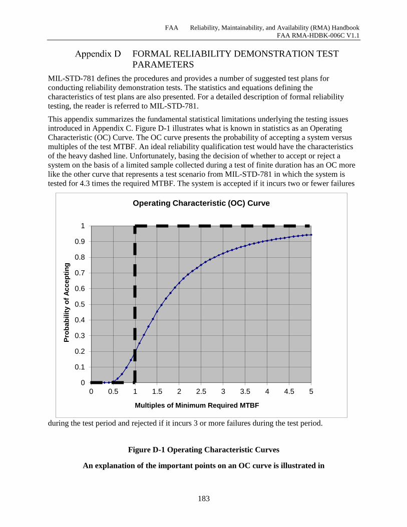
FAA Reliability, Maintainability, and Availability (RMA) Handbook
FAA RMA-HDBK-006C V1.1
183
FORMAL RELIABILITY DEMONSTRATION TEST
PARAMETERS
MIL-STD-781 defines the procedures and provides a number of suggested test plans for
conducting reliability demonstration tests. The statistics and equations defining the
characteristics of test plans are also presented. For a detailed description of formal reliability
testing, the reader is referred to MIL-STD-781.
This appendix summarizes the fundamental statistical limitations underlying the testing issues
introduced in Appendix C. Figure D-1 illustrates what is known in statistics as an Operating
Characteristic (OC) Curve. The OC curve presents the probability of accepting a system versus
multiples of the test MTBF. An ideal reliability qualification test would have the characteristics
of the heavy dashed line. Unfortunately, basing the decision of whether to accept or reject a
system on the basis of a limited sample collected during a test of finite duration has an OC more
like the other curve that represents a test scenario from MIL-STD-781 in which the system is
tested for 4.3 times the required MTBF. The system is accepted if it incurs two or fewer failures
during the test period and rejected if it incurs 3 or more failures during the test period.
Figure D-1 Operating Characteristic Curves
An explanation of the important points on an OC curve is illustrated in
0
0.1
0.2
0.3
0.4
0.5
0.6
0.7
0.8
0.9
1
0 0.5 1 1.5 2 2.5 3 3.5 4 4.5 5
Pro
bab
ilit
y o
f A
ccep
tin
g
Multiples of Minimum Required MTBF
Operating Characteristic (OC) Curve
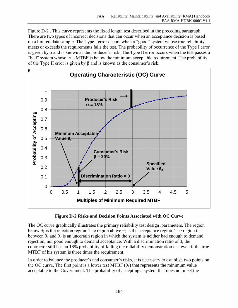
FAA Reliability, Maintainability, and Availability (RMA) Handbook
FAA RMA-HDBK-006C V1.1
184
Figure D-2 . This curve represents the fixed length test described in the preceding paragraph.
There are two types of incorrect decisions that can occur when an acceptance decision is based
on a limited data sample. The Type I error occurs when a “good” system whose true reliability
meets or exceeds the requirements fails the test. The probability of occurrence of the Type I error
is given by α and is known as the producer’s risk. The Type II error occurs when the test passes a
“bad” system whose true MTBF is below the minimum acceptable requirement. The probability
of the Type II error is given by β and is known as the consumer’s risk.
Figure D-2 Risks and Decision Points Associated with OC Curve
The OC curve graphically illustrates the primary reliability test design .parameters. The region
below θ1 is the rejection region. The region above θ0 is the acceptance region. The region in
between θ1 and θ0 is an uncertain region in which the system is neither bad enough to demand
rejection, nor good enough to demand acceptance. With a discrimination ratio of 3, the
contractor still has an 18% probability of failing the reliability demonstration test even if the true
MTBF of his system is three times the requirement.
In order to balance the producer’s and consumer’s risks, it is necessary to establish two points on
the OC curve. The first point is a lower test MTBF (θ1) that represents the minimum value
acceptable to the Government. The probability of accepting a system that does not meet the
0
0.1
0.2
0.3
0.4
0.5
0.6
0.7
0.8
0.9
1
0 0.5 1 1.5 2 2.5 3 3.5 4 4.5 5
Pro
ba
bilit
y o
f A
cc
ep
tin
g
Multiples of Minimum Required MTBF
Operating Characteristic (OC) Curve
Discrimination Ratio = 3
Producer's Risk
α = 18%
Consumer's Riskβ = 20%
SpecifiedValue θ0
Minimum AcceptableValue θ1
β α
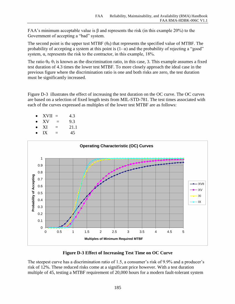
FAA Reliability, Maintainability, and Availability (RMA) Handbook
FAA RMA-HDBK-006C V1.1
185
FAA’s minimum acceptable value is β and represents the risk (in this example 20%) to the
Government of accepting a “bad” system.
The second point is the upper test MTBF (θ0) that represents the specified value of MTBF. The
probability of accepting a system at this point is (1- α) and the probability of rejecting a “good”
system, α, represents the risk to the contractor, in this example, 18%.
The ratio θ0/ θ1 is known as the discrimination ratio, in this case, 3. This example assumes a fixed
test duration of 4.3 times the lower test MTBF. To more closely approach the ideal case in the
previous figure where the discrimination ratio is one and both risks are zero, the test duration
must be significantly increased.
Figure D-3 illustrates the effect of increasing the test duration on the OC curve. The OC curves
are based on a selection of fixed length tests from MIL-STD-781. The test times associated with
each of the curves expressed as multiples of the lower test MTBF are as follows:
XVII = 4.3
XV = 9.3
XI = 21.1
IX = 45
Figure D-3 Effect of Increasing Test Time on OC Curve
The steepest curve has a discrimination ratio of 1.5, a consumer’s risk of 9.9% and a producer’s
risk of 12%. These reduced risks come at a significant price however. With a test duration
multiple of 45, testing a MTBF requirement of 20,000 hours for a modern fault-tolerant system
0
0.1
0.2
0.3
0.4
0.5
0.6
0.7
0.8
0.9
1
0 0.5 1 1.5 2 2.5 3 3.5 4 4.5 5
Pro
bab
ilit
y o
f A
ccep
tin
g
Multiples of Minimum Required MTBF
Operating Characteristic (OC) Curves
XVII
XV
XI
IX
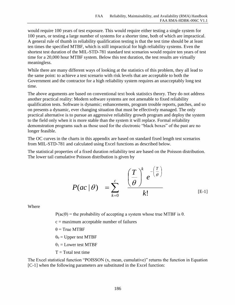
FAA Reliability, Maintainability, and Availability (RMA) Handbook
FAA RMA-HDBK-006C V1.1
186
would require 100 years of test exposure. This would require either testing a single system for
100 years, or testing a large number of systems for a shorter time, both of which are impractical.
A general rule of thumb in reliability qualification testing is that the test time should be at least
ten times the specified MTBF, which is still impractical for high reliability systems. Even the
shortest test duration of the MIL-STD-781 standard test scenarios would require ten years of test
time for a 20,000 hour MTBF system. Below this test duration, the test results are virtually
meaningless.
While there are many different ways of looking at the statistics of this problem, they all lead to
the same point: to achieve a test scenario with risk levels that are acceptable to both the
Government and the contractor for a high reliability system requires an unacceptably long test
time.
The above arguments are based on conventional text book statistics theory. They do not address
another practical reality: Modern software systems are not amenable to fixed reliability
qualification tests. Software is dynamic; enhancements, program trouble reports, patches, and so
on presents a dynamic, ever changing situation that must be effectively managed. The only
practical alternative is to pursue an aggressive reliability growth program and deploy the system
to the field only when it is more stable than the system it will replace. Formal reliability
demonstration programs such as those used for the electronic “black boxes” of the past are no
longer feasible.
The OC curves in the charts in this appendix are based on standard fixed length test scenarios
from MIL-STD-781 and calculated using Excel functions as described below.
The statistical properties of a fixed duration reliability test are based on the Poisson distribution.
The lower tail cumulative Poisson distribution is given by
c
k
Tk
k
eT
acP0 !
)|(
[E-1]
Where
P(ac|θ) = the probability of accepting a system whose true MTBF is θ.
c = maximum acceptable number of failures
θ = True MTBF
θ0 = Upper test MTBF
θ1 = Lower test MTBF
T = Total test time
The Excel statistical function “POISSON (x, mean, cumulative)” returns the function in Equation
[C-1] when the following parameters are substituted in the Excel function:

FAA Reliability, Maintainability, and Availability (RMA) Handbook
FAA RMA-HDBK-006C V1.1
187
POISSON (c, T/θ, TRUE)
The charts were calculated using the fixed values for c and T associated with each of the sample
test plans from MIL-STD-781. The x axis of the charts is normalized to multiples of the lower
test MTBF, θ1, and covers a range of 0.1 to 5.0 times the minimum MTBF acceptable to the
Government.
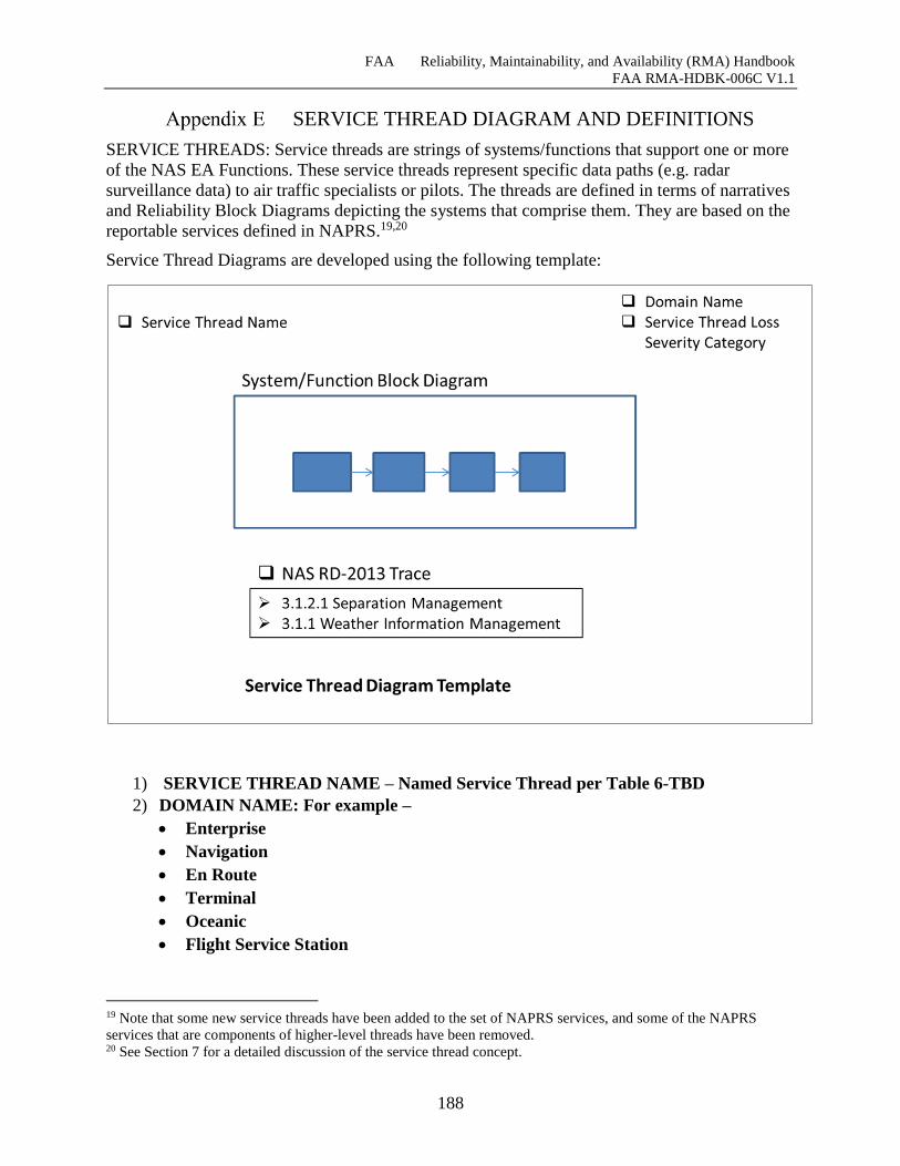
FAA Reliability, Maintainability, and Availability (RMA) Handbook
FAA RMA-HDBK-006C V1.1
188
SERVICE THREAD DIAGRAM AND DEFINITIONS
SERVICE THREADS: Service threads are strings of systems/functions that support one or more
of the NAS EA Functions. These service threads represent specific data paths (e.g. radar
surveillance data) to air traffic specialists or pilots. The threads are defined in terms of narratives
and Reliability Block Diagrams depicting the systems that comprise them. They are based on the
reportable services defined in NAPRS.19,20
Service Thread Diagrams are developed using the following template:
1) SERVICE THREAD NAME – Named Service Thread per Table 6-TBD
2) DOMAIN NAME: For example –
Enterprise
Navigation
En Route
Terminal
Oceanic
Flight Service Station
19 Note that some new service threads have been added to the set of NAPRS services, and some of the NAPRS
services that are components of higher-level threads have been removed. 20 See Section 7 for a detailed discussion of the service thread concept.
FAA Reliability, Maintainability, and Availability (RMA) Handbook
FAA RMA-HDBK-006C V1.1
189
1) SYSTEM/FUNCTION BLOCK DIAGRAM – Depicts the systems/functions and their
relationships in block-diagram form.
2) NAS- RD-2013 TRACE – Provides a mapping to the associated NAS-RD-2013
enterprise-level functional requirements per Table TBD.
3) SERVICE THREAD LOSS SEVERITY CATEGORY (STLSC): Each service thread
is assigned a Service Thread Loss Severity Category based on the severity of impact that
loss of the thread could have on the safe and/or efficient operation and control of aircraft.
(See Section 7.4 for a detailed discussion of the STLSC concept.) The Service Thread
Loss Severity Categories are:
Safety-Critical - A key service in the protection of human life. Loss of a Safety-
Critical service increases the risk in the loss of human life.
Efficiency-Critical - A key service that is used in present operation of the NAS. Loss
of an Efficiency-Critical Service has a major impact in the present operational
capacity.
Essential - A service that if lost would significantly raise the risk associated with
providing efficient NAS operations.
Routine - A service which, if lost, would have a minor impact on the risk associated
with providing safe and efficient NAS operations.
In a STLSC, Service Threads can also be characterized as Remote/Distributed where
loss of a service thread element, i.e., radar, air/ground communications site, or display
console, would incrementally degrade the overall effectiveness of the service thread but
would not render the service thread inoperable21.
21 21 Remote/Distributed STLSC is specific to this Handbook and does not appear in NAS-RD-2013.
FAA Reliability, Maintainability, and Availability (RMA) Handbook
FAA RMA-HDBK-006C V1.1
190
Appendix E Table of Figures
Figure E-1 Functional Notional Architecture ................................ Error! Bookmark not defined.
Figure E-2 Automatic Dependent Surveillance Service (ADSS) .. Error! Bookmark not defined.
Figure E-3 Airport Surface Detection Equipment (ASDES) ......... Error! Bookmark not defined.
Figure E-4 Beacon Data (Digitized) (BDAT) ................................ Error! Bookmark not defined.
Figure E-5 Backup Emergency Communications Service (BUECS) .......... Error! Bookmark not
defined.
Figure E-6 Composite Flight Data Processing Service (CFAD) ... Error! Bookmark not defined.
Figure E-7 Composite Oceanic Display and Planning Service (CODAP) .. Error! Bookmark not
defined.
Figure E-8 Anchorage Composite Offshore Flight Data Service (COFAD) Error! Bookmark not
defined.
Figure E-9 Composite Radar Data Processing Service (CRAD) (CCCH/EBUS) ................ Error!
Bookmark not defined.
Figure E-10 Composite Radar Data Processing Service (CRAD) (EAS/EBUS)Error! Bookmark
not defined.
Figure E-11 En Route Communications (ECOM) ......................... Error! Bookmark not defined.
Figure E-12 En Route Terminal Automated Radar Service (ETARS) ........ Error! Bookmark not
defined.
Figure E-13 FSS Communications Service (FCOM) .................... Error! Bookmark not defined.
Figure E-14 Flight Data Entry and Printout Service (FDAT) ........ Error! Bookmark not defined.
Figure E-15 Flight Data Input/Output Remote (FDIOR) .............. Error! Bookmark not defined.
Figure E-16 Flight Service Station Automated Service (FSSAS) . Error! Bookmark not defined.
Figure E-17 Interfacility Data Service (IDAT) .............................. Error! Bookmark not defined.
Figure E-18 Low Level Wind Service (LLWS) ............................ Error! Bookmark not defined.
Figure E-19 MODE-S Data Link Data Service (MDAT) .............. Error! Bookmark not defined.
Figure E-20 MODE-S Secondary Radar Service (MSEC) ............ Error! Bookmark not defined.
Figure E-21 NADIN Service Threads (NADS, NAMS, NDAT) .. Error! Bookmark not defined.
Figure E-22 Radar Data (Digitized) (RDAT) ................................ Error! Bookmark not defined.
Figure E-23 Remote Monitoring/Maintenance Logging System Service (RMLSS) ............. Error!
Bookmark not defined.
Figure E-24 Remote Tower Alphanumeric Display System Service (RTADS). Error! Bookmark
not defined.
Figure E-25 Remote Tower Display Service (RTDS) ................... Error! Bookmark not defined.
Figure E-26 Runway Visual Range Service (RVRS) .................... Error! Bookmark not defined.
Figure E-27 Terminal Automated Radar Service (TARS) ............ Error! Bookmark not defined.
Figure E-28 Terminal Communications Service (TCOM) ............ Error! Bookmark not defined.
Figure E-29 Terminal Doppler Weather Radar Service (TDWRS) ............. Error! Bookmark not
defined.
Figure E-30 Traffic Flow Management System Service (TFMSS) ............. Error! Bookmark not
defined.
Figure E-31 Terminal Radar Service (TRAD) ............................... Error! Bookmark not defined.
Figure E-32 Terminal Surveillance Backup (TSB) (NEW) ........... Error! Bookmark not defined.
Figure E-33 Terminal Secondary Radar (TSEC) ........................... Error! Bookmark not defined.
Figure E-34 Terminal Voice Switch (TVS) (NAPRS Facility) ..... Error! Bookmark not defined.
Figure E-35 Terminal Voice Switch Backup (TVSB) (New) ........ Error! Bookmark not defined.
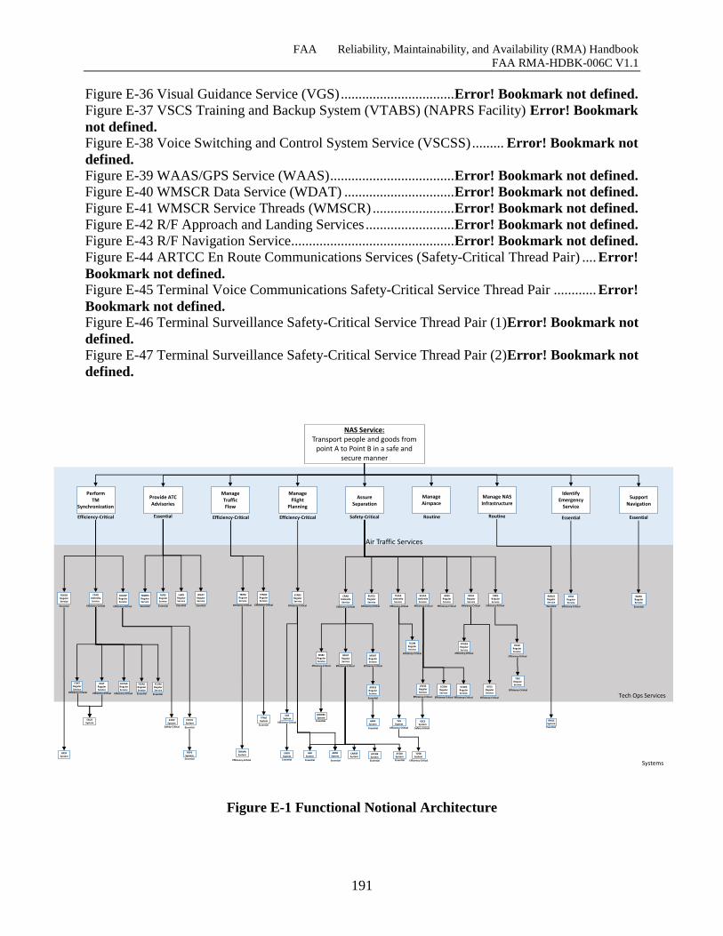
FAA Reliability, Maintainability, and Availability (RMA) Handbook
FAA RMA-HDBK-006C V1.1
191
Figure E-36 Visual Guidance Service (VGS) ................................ Error! Bookmark not defined.
Figure E-37 VSCS Training and Backup System (VTABS) (NAPRS Facility) Error! Bookmark
not defined.
Figure E-38 Voice Switching and Control System Service (VSCSS) ......... Error! Bookmark not
defined.
Figure E-39 WAAS/GPS Service (WAAS) ................................... Error! Bookmark not defined.
Figure E-40 WMSCR Data Service (WDAT) ............................... Error! Bookmark not defined.
Figure E-41 WMSCR Service Threads (WMSCR) ....................... Error! Bookmark not defined.
Figure E-42 R/F Approach and Landing Services ......................... Error! Bookmark not defined.
Figure E-43 R/F Navigation Service.............................................. Error! Bookmark not defined.
Figure E-44 ARTCC En Route Communications Services (Safety-Critical Thread Pair) .... Error!
Bookmark not defined.
Figure E-45 Terminal Voice Communications Safety-Critical Service Thread Pair ............ Error!
Bookmark not defined.
Figure E-46 Terminal Surveillance Safety-Critical Service Thread Pair (1)Error! Bookmark not
defined.
Figure E-47 Terminal Surveillance Safety-Critical Service Thread Pair (2)Error! Bookmark not
defined.
Figure E-1 Functional Notional Architecture
NAS Service:Transport people and goods from
point A to Point B in a safe and secure manner
Assure Separation
Manage Airspace
Provide ATC Advisories
Manage Traffic Flow
Perform TM
Synchronization
Identify Emergency
Service
Support Navigation
Manage NAS Infrastructure
Efficiency-Critical Efficiency-CriticalEssential Routine Essential EssentialRoutineSafety-Critical
ECVEX Umbrella Service
BUECS RegularService
CRAD UmbrellaService
CODAPRegularService
CFAD UmbrellaService
FDIOR RegularService
ADSS RegularService
RDAT RegularService
FDATRegularService
TFMSS RegularService
IDATRegularService
BDATRegularService
MDATRegularService
MSECRegularService
Essential Efficiency-Critical Efficiency-CriticalEfficiency-Critical Efficiency-CriticalEfficiency-CriticalEfficiency-Critical Efficiency-Critical Efficiency-Critical
Efficiency-CriticalEfficiency-Critical Efficiency-Critical
Efficiency-Critical Efficiency-Critical
Air Traffic Services
Tech Ops Services
RFSPSystem
ATOPSystem
FDPSSystem
TFMSSystem VSCS
System
VTABSRegular Service
CARSRSystem
ATCRBSystem
ATCBISystem
MODESSystem
EBUSSystem
FDIOCSystem
Essential
Essential
Safety-Critical
Essential
EssentialEssential
Safety-Critical
Efficiency-Critical
Essential
Manage Flight
Planning
Efficiency-Critical
EASSystem
ETARSRegularService
EADSSystem
ASRSystem
ARSRSystem
EssentialEssential Essential
Efficiency-Critical
Efficiency-Critical
Systems
FSSASRegularService
TCVEXUmbrella Service
TCOMRegularService
Efficiency-Critical
ASDESystem
ECOMRegularService
TARS RegularService
Efficiency-Critical
RTDSRegularService
RTADSRegularService
TRADRegularService
Efficiency-CriticalEfficiency-Critical
Efficiency-Critical
Essential
Efficiency-Critical
Efficiency-Critical
Efficiency-Critical
Essential
WAAS RegularService
Essential
LLWS RegularService
Essential
WDATRegularService
Essential
TVS System
Efficiency-Critical
TVSBSystem
Efficiency-Critical
COFADRegularService
Efficiency-Critical
ECSSRegular Service
Efficiency-Critical
RVRSRegularService
Essential
TBFM RegularService
Efficiency-Critical
TBFMRSystem
Efficiency-Critical
TDWRSRegularService
Essential
RMLSSRegular Service
Essential
RMLSSystem
Essential
FCOMRegularService
Essential
VSCSSRegularService
Efficiency-Critical
TSECRegularService
ASDESRegularService
Essential
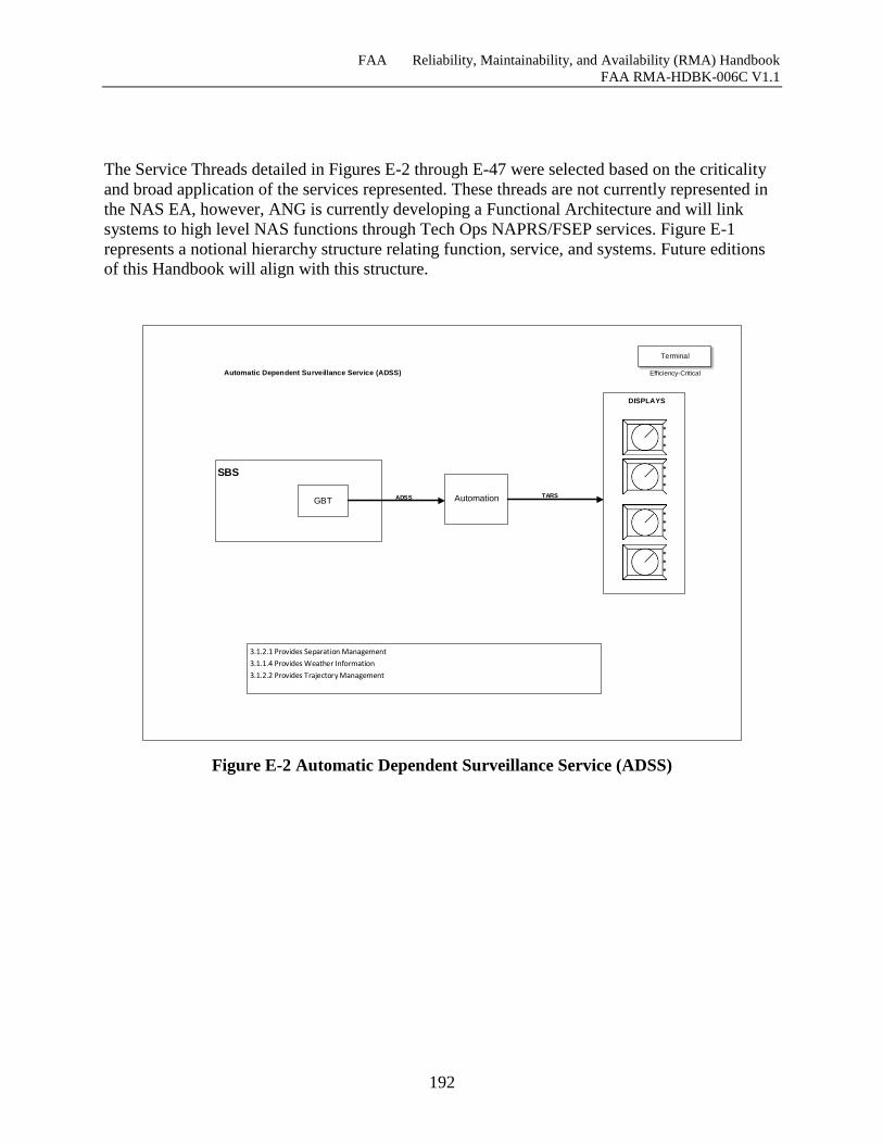
FAA Reliability, Maintainability, and Availability (RMA) Handbook
FAA RMA-HDBK-006C V1.1
192
The Service Threads detailed in Figures E-2 through E-47 were selected based on the criticality
and broad application of the services represented. These threads are not currently represented in
the NAS EA, however, ANG is currently developing a Functional Architecture and will link
systems to high level NAS functions through Tech Ops NAPRS/FSEP services. Figure E-1
represents a notional hierarchy structure relating function, service, and systems. Future editions
of this Handbook will align with this structure.
Automatic Dependent Surveillance Service (ADSS)
DISPLAYS
*
*
*
*
*
*
*
*
*
*
*
*
Terminal
GBT
SBS
ADSS Automation TARS
3.1.2.1 Provides Separation Management
3.1.1.4 Provides Weather Information
3.1.2.2 Provides Trajectory Management
Efficiency-Critical
Figure E-2 Automatic Dependent Surveillance Service (ADSS)
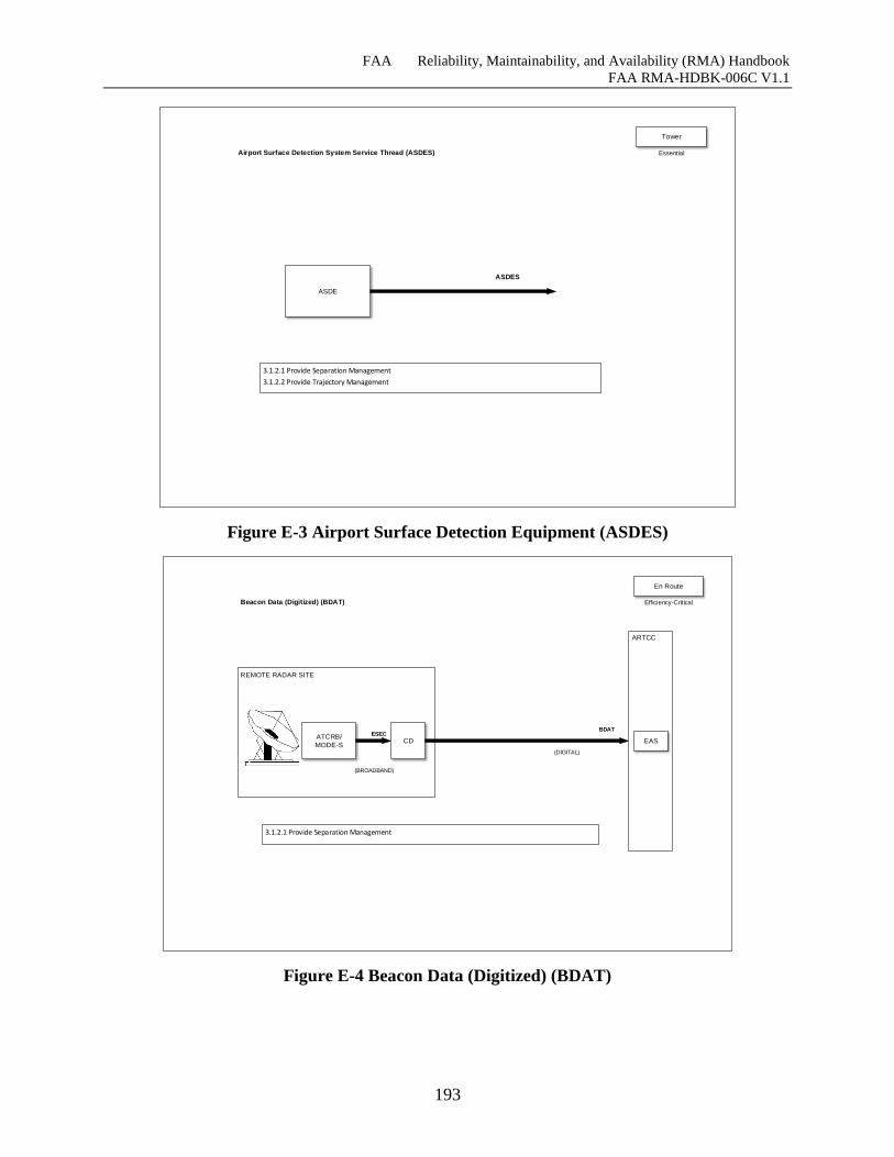
FAA Reliability, Maintainability, and Availability (RMA) Handbook
FAA RMA-HDBK-006C V1.1
193
ASDE
ASDES
3.1.2.1 Provide Separation Management
3.1.2.2 Provide Trajectory Management
Airport Surface Detection System Service Thread (ASDES)
Tower
Essential
Figure E-3 Airport Surface Detection Equipment (ASDES)
REMOTE RADAR SITE
ATCRB/
MODE-S
3.1.2.1 Provide Separation Management
Beacon Data (Digitized) (BDAT)
CD
ARTCC
ESEC
(BROADBAND)
BDAT
(DIGITAL)
En Route
EAS
Efficiency-Critical
Figure E-4 Beacon Data (Digitized) (BDAT)
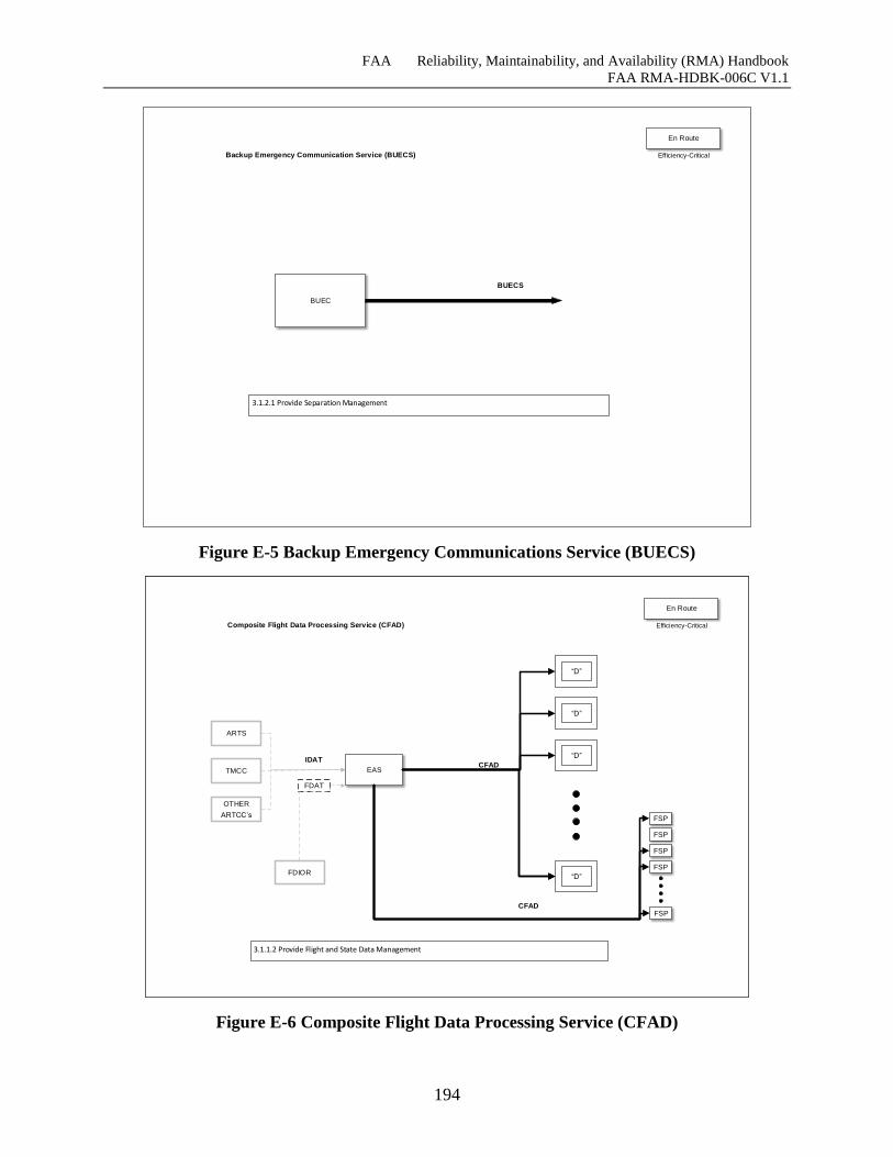
FAA Reliability, Maintainability, and Availability (RMA) Handbook
FAA RMA-HDBK-006C V1.1
194
BUEC
BUECS
3.1.2.1 Provide Separation Management
Backup Emergency Communication Service (BUECS)
En Route
Efficiency-Critical
Figure E-5 Backup Emergency Communications Service (BUECS)
ARTS
CCCHCFAD
1012 Provide Flight Data Management (2)
Composite Flight Data Processing Service (CFAD)
DSR
“D”
“D”
“D”
“D”
FSP
FSP
FSP
FSP
FSP
CFAD
ARTS
TMCC
OTHER
ARTCC’s
FDIOR
FDAT
IDAT
En Route
ARTS
EASCFAD
3.1.1.2 Provide Flight and State Data Management
Composite Flight Data Processing Service (CFAD)
“D”
“D”
“D”
“D”
FSP
FSP
FSP
FSP
FSP
CFAD
ARTS
TMCC
OTHER
ARTCC’s
FDIOR
FDAT
IDAT
En Route
Efficiency-Critical
Figure E-6 Composite Flight Data Processing Service (CFAD)
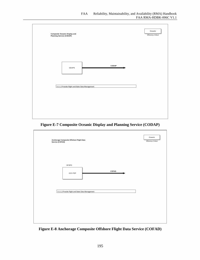
FAA Reliability, Maintainability, and Availability (RMA) Handbook
FAA RMA-HDBK-006C V1.1
195
ODAPS
CODAP
3.1.1.2 Provide Flight and State Data Management
Composite Oceanic Display and
Planning Service (CODAP)
Oceanic
Efficiency-Critical
Figure E-7 Composite Oceanic Display and Planning Service (CODAP)
OCS FDP
COFAD
3.1.1.2 Provide Flight and State Data Management
Anchorage Composite Offshore Flight Data
Service (COFAD)
OFDPS
Oceanic
Efficiency-Critical
Figure E-8 Anchorage Composite Offshore Flight Data Service (COFAD)
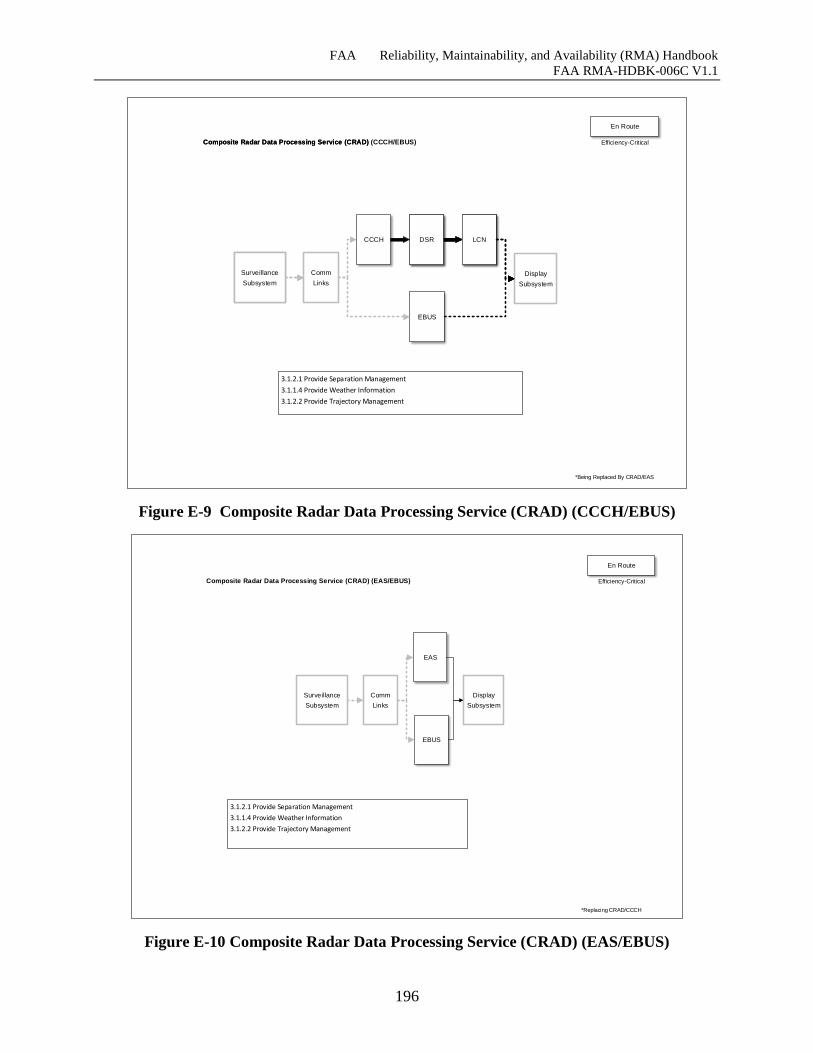
FAA Reliability, Maintainability, and Availability (RMA) Handbook
FAA RMA-HDBK-006C V1.1
196
Composite Radar Data Processing Service (CRAD)
DSR LCN
Surveillance
Subsystem
En Route
3.1.2.1 Provide Separation Management
3.1.1.4 Provide Weather Information
3.1.2.2 Provide Trajectory Management
Composite Radar Data Processing Service (CRAD) (CCCH/EBUS)
LCN
Display
Subsystem
Surveillance
Subsystem
Comm
Links
CCCH DSR
*Being Replaced By CRAD/EAS
Efficiency-Critical
EBUS
Figure E-9 Composite Radar Data Processing Service (CRAD) (CCCH/EBUS)
1021 Provide Aircraft to Aircraft Separation (2)
1022 Provide Aircraft to Terrain Separation (2)
1023 Provide Aircraft to Airspace Separation (2)
1031 Provide Weather Information (3)
1032 Provide Traffic Advisories (3)
1041 Provide Airborne Traffic Management Synchronization (3)
Composite Radar Data Processing Service (CRAD)
DSRSurveillance
Subsystem
3.1.2.1 Provide Separation Management
3.1.1.4 Provide Weather Information
3.1.2.2 Provide Trajectory Management
Composite Radar Data Processing Service (CRAD) (EAS/EBUS)
Display
Subsystem
Comm
Links
EAS
Surveillance
Subsystem
En Route
*Replacing CRAD/CCCH
Efficiency-Critical
EBUS
Figure E-10 Composite Radar Data Processing Service (CRAD) (EAS/EBUS)
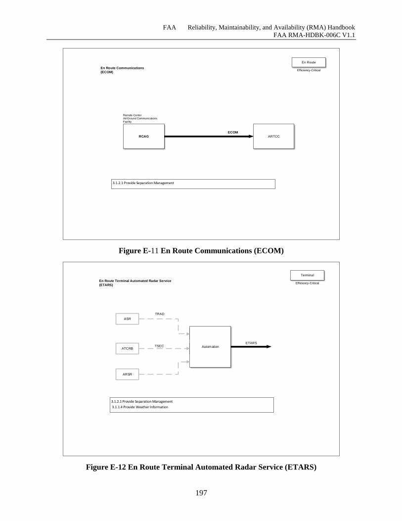
FAA Reliability, Maintainability, and Availability (RMA) Handbook
FAA RMA-HDBK-006C V1.1
197
RCAG
ECOM
3.1.2.1 Provide Separation Management
En Route Communications
(ECOM)
ARTCC
Remote Center Air/Ground Communications Facility
En Route
Efficiency-Critical
Figure E-11 En Route Communications (ECOM)
ARTS
ARTS
ARTS
ETARS
3.1.2.1 Provide Separation Management
3.1.1.4 Provide Weather Information
En Route Terminal Automated Radar Service
(ETARS)
Automation
ASR
ATCRBTSEC
TRAD
Terminal
Efficiency-Critical
ARSR
Figure E-12 En Route Terminal Automated Radar Service (ETARS)
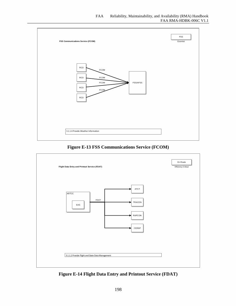
FAA Reliability, Maintainability, and Availability (RMA) Handbook
FAA RMA-HDBK-006C V1.1
198
3.1.1.4 Provide Weather Information
FSS Communications Service (FCOM)
FSS/AFSS
FCOM
RCO
RCO
RCO
RCO
FCOM
FCOM
FCOM
FSS
Essential
Figure E-13 FSS Communications Service (FCOM)
3.1.1.2 Provide Flight and State Data Management
Flight Data Entry and Printout Service (FDAT)
FDAT
ARTCC
CERAP
TRACON
ATCT
En Route
EAS
RAPCON
Efficiency-Critical
Figure E-14 Flight Data Entry and Printout Service (FDAT)
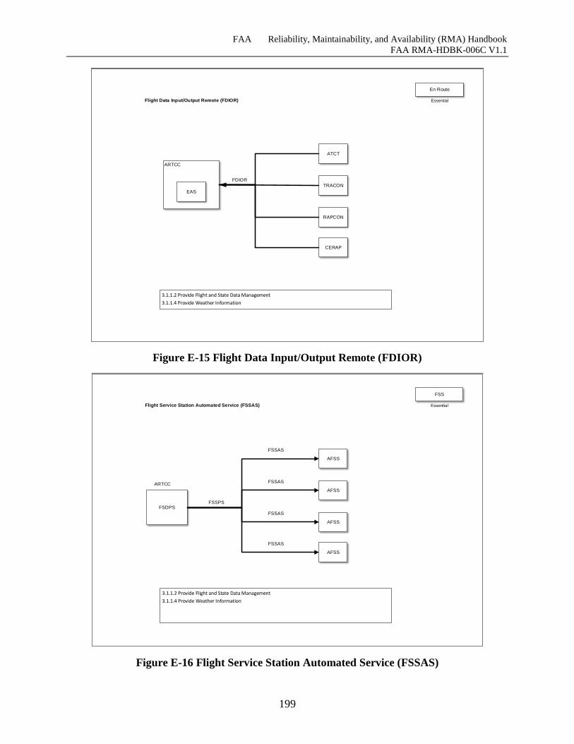
FAA Reliability, Maintainability, and Availability (RMA) Handbook
FAA RMA-HDBK-006C V1.1
199
3.1.1.2 Provide Flight and State Data Management
3.1.1.4 Provide Weather Information
Flight Data Input/Output Remote (FDIOR)
FDIOR
ARTCC
CERAP
TRACON
ATCT
En Route
EAS
RAPCON
Essential
Figure E-15 Flight Data Input/Output Remote (FDIOR)
3.1.1.2 Provide Flight and State Data Management
3.1.1.4 Provide Weather Information
Flight Service Station Automated Service (FSSAS)
FSSAS
FSDPS
AFSS
FSSAS
FSSAS
AFSS
AFSS
AFSS
FSSAS
FSSPS
ARTCC
FSS
Essential
Figure E-16 Flight Service Station Automated Service (FSSAS)
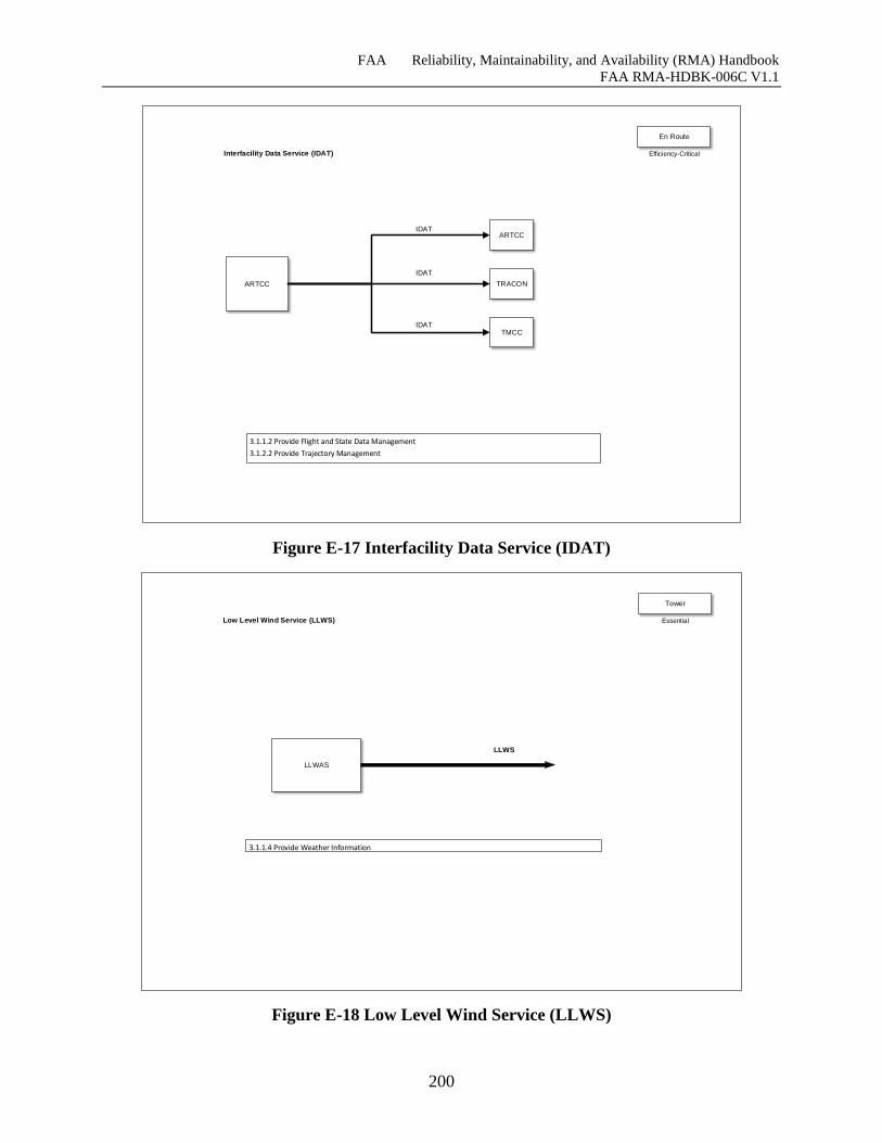
FAA Reliability, Maintainability, and Availability (RMA) Handbook
FAA RMA-HDBK-006C V1.1
200
3.1.1.2 Provide Flight and State Data Management
3.1.2.2 Provide Trajectory Management
Interfacility Data Service (IDAT)
ARTCC TRACON
ARTCC
TMCC
IDAT
IDAT
IDAT
En Route
Efficiency-Critical
Figure E-17 Interfacility Data Service (IDAT)
LLWAS
LLWS
3.1.1.4 Provide Weather Information
Low Level Wind Service (LLWS)
Tower
Essential
Figure E-18 Low Level Wind Service (LLWS)
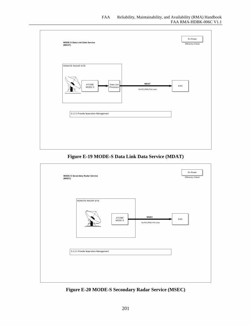
FAA Reliability, Maintainability, and Availability (RMA) Handbook
FAA RMA-HDBK-006C V1.1
201
REMOTE RADAR SITE
ATCRB/
MODE-S
3.1.2.1 Provide Separation Management
MODE-S Data Link Data Service
(MDAT)
Data Link
Processor
MDAT
Via RCL/RML/FAA Lines
En Route
EAS
Efficiency-Critical
Figure E-19 MODE-S Data Link Data Service (MDAT)
REMOTE RADAR SITE
3.1.2.1 Provide Separation Management
MODE-S Secondary Radar Service
(MSEC)
MSEC
Via RCL/RML/FAA Lines
ATCRB/
MODE-S
En Route
EAS
Efficiency-Critical
Figure E-20 MODE-S Secondary Radar Service (MSEC)
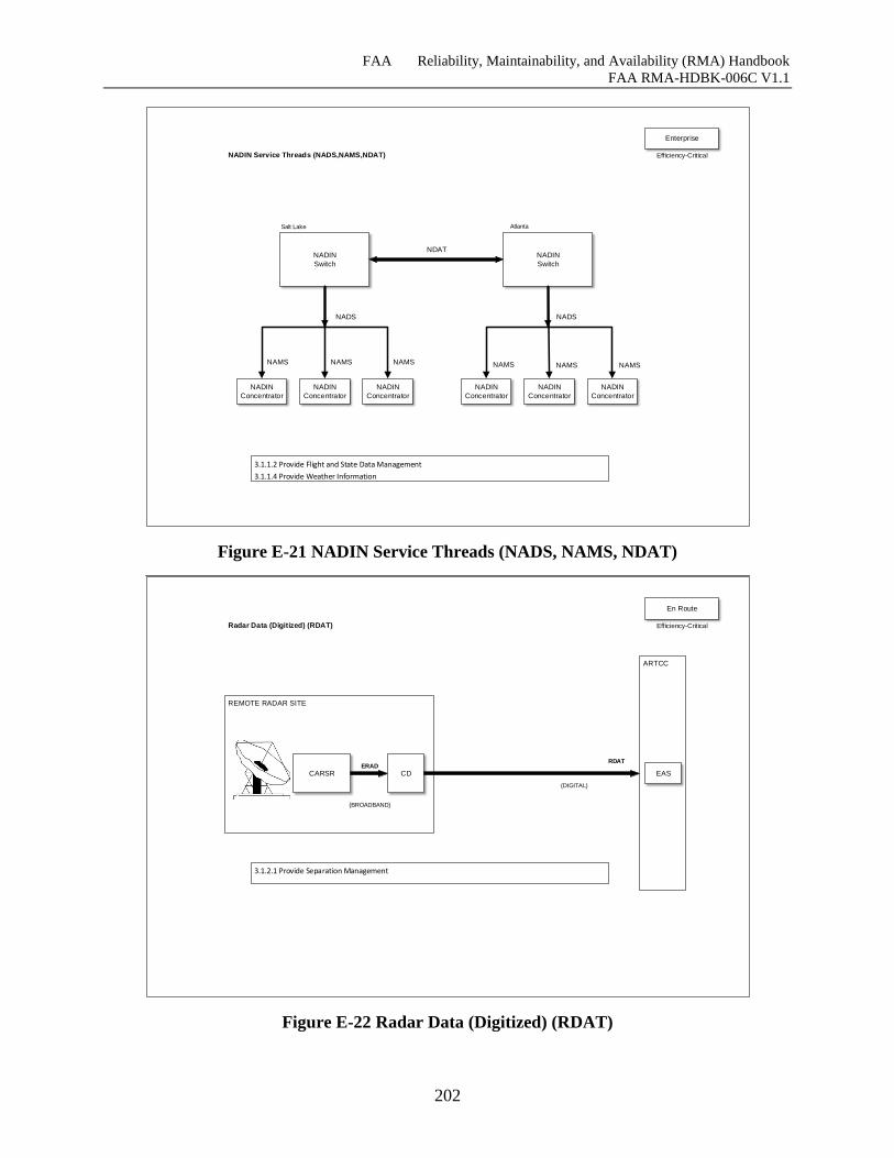
FAA Reliability, Maintainability, and Availability (RMA) Handbook
FAA RMA-HDBK-006C V1.1
202
NADIN
Switch
NADIN
Switch
NADIN
Switch
NDAT
3.1.1.2 Provide Flight and State Data Management
3.1.1.4 Provide Weather Information
NADIN Service Threads (NADS,NAMS,NDAT)
NADIN
Switch
Atlanta
NADS
Salt Lake
NADS
NADIN
Concentrator
NADIN
Concentrator
NADIN
Concentrator
NADIN
Concentrator
NADIN
Concentrator
NADIN
Concentrator
NAMS NAMS NAMS NAMS NAMS NAMS
Enterprise
Efficiency-Critical
Figure E-21 NADIN Service Threads (NADS, NAMS, NDAT)
REMOTE RADAR SITE
CARSR
3.1.2.1 Provide Separation Management
Radar Data (Digitized) (RDAT)
CD
ARTCC
ERAD
(BROADBAND)
RDAT
(DIGITAL)
En Route
EAS
Efficiency-Critical
Figure E-22 Radar Data (Digitized) (RDAT)
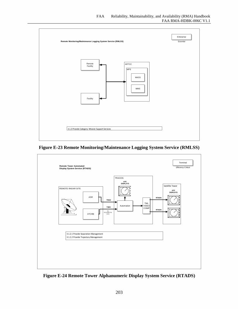
FAA Reliability, Maintainability, and Availability (RMA) Handbook
FAA RMA-HDBK-006C V1.1
203
Remote
Facility
3.1.3 Provide Category: Mission Support Services
Remote Monitoring/Maintenance Logging System Service (RMLSS)
Enterprise
Facility
ARTCC
MPS
MASS
MMS
Essential
Figure E-23 Remote Monitoring/Maintenance Logging System Service (RMLSS)
3.1.2.1 Provide Separation Management
3.1.2.2 Provide Trajectory Management
Remote Tower Automated
Display System Service (RTADS)
Terminal
ASR
ART
S
ART
S
ARTS
ART
S
REMOTE RADAR SITE
ASR
Satellite Tower
TRACON
ATCRB
Automation
TML
VIDEO
COMP
ATC DISPLAYS
TSEC
TRAD
Via
RCL/RML/FAA
Lines
*
*
*
*
*
*
RTADS
RTADS
*
*
*
ATC DISPLAYS
Efficiency-Critical
Figure E-24 Remote Tower Alphanumeric Display System Service (RTADS)
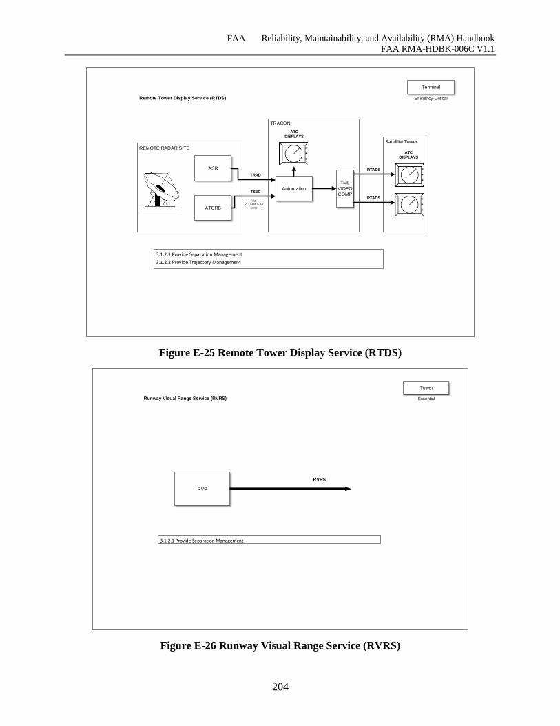
FAA Reliability, Maintainability, and Availability (RMA) Handbook
FAA RMA-HDBK-006C V1.1
204
ASR
3.1.2.1 Provide Separation Management
3.1.2.2 Provide Trajectory Management
Remote Tower Display Service (RTDS)
Terminal
ART
S
ART
S
ARTS
ART
S
REMOTE RADAR SITE
ASR
Satellite Tower
TRACON
ATCRB
Automation
TML
VIDEO
COMP
ATC DISPLAYS
TSEC
TRAD
Via
RCL/RML/FAA
Lines
*
*
*
*
*
*
RTADS
RTADS
*
*
*
ATC DISPLAYS
Efficiency-Critical
Figure E-25 Remote Tower Display Service (RTDS)
RVR
RVRS
3.1.2.1 Provide Separation Management
Runway Visual Range Service (RVRS)
Tower
Essential
Figure E-26 Runway Visual Range Service (RVRS)
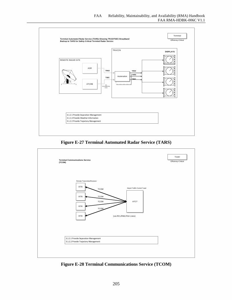
FAA Reliability, Maintainability, and Availability (RMA) Handbook
FAA RMA-HDBK-006C V1.1
205
ARTS
ARTS
ARTS
ART
S
ART
S
ARTS
ARTS
REMOTE RADAR SITE
ASR
3.1.2.1 Provide Separation Management
3.1.1.4 Provide Weather Information
3.1.2.2 Provide Trajectory Management
Terminal Automated Radar Service (TARS) Showing TRAD/TSEC Broadband
Backup to TARS for Safety-Critical Terminal Radar Service
TRACON
ATCRB
Automation
DISPLAYS
TSEC
TRAD
Via
RCL/RML/FAA
Lines
*
*
*
*
*
*
*
*
*
*
*
*
TRAD
TARS
TSEC
Terminal
Efficiency-Critical
Figure E-27 Terminal Automated Radar Service (TARS)
3.1.2.1 Provide Separation Management
3.1.2.2 Provide Trajectory Management
Terminal Communications Service
(TCOM)
ATCT
TCOM
RTR
RTR
RTR
RTR
TCOM
TCOM
TCOM
Remote Transmitter/Receiver
Airport Traffic Control Tower
(via RCL/RML/FAA Lines)
Tower
Efficiency-Critical
Figure E-28 Terminal Communications Service (TCOM)
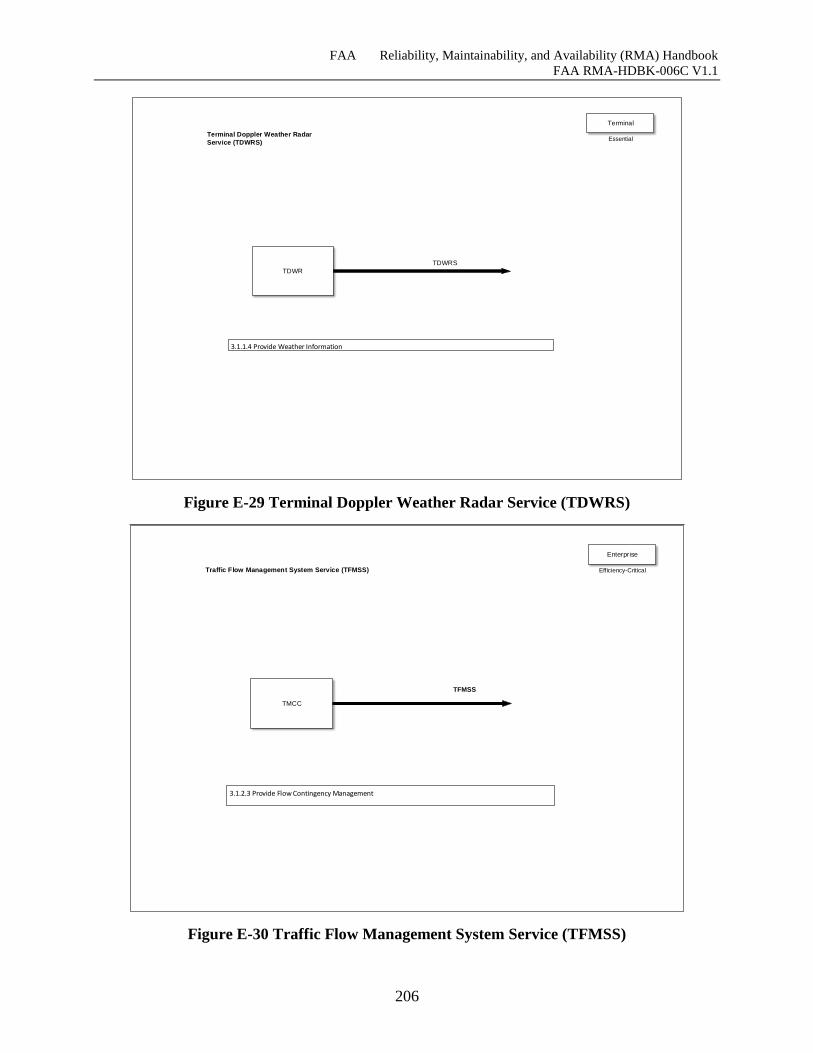
FAA Reliability, Maintainability, and Availability (RMA) Handbook
FAA RMA-HDBK-006C V1.1
206
TDWR
TDWRS
3.1.1.4 Provide Weather Information
Terminal Doppler Weather Radar
Service (TDWRS)
Terminal
Essential
Figure E-29 Terminal Doppler Weather Radar Service (TDWRS)
TMCC
TFMSS
3.1.2.3 Provide Flow Contingency Management
Traffic Flow Management System Service (TFMSS)
Enterprise
Efficiency-Critical
Figure E-30 Traffic Flow Management System Service (TFMSS)
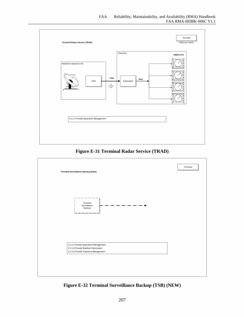
FAA Reliability, Maintainability, and Availability (RMA) Handbook
FAA RMA-HDBK-006C V1.1
207
ARTS
ARTS
ARTS
ART
S
ART
S
ARTS
ARTS
REMOTE RADAR SITE
ASR
3.1.2.1 Provide Separation Management
Terminal Radar Service (TRAD)
TRACON
Automation
DISPLAYS
TRAD
Via
RCL//FAA
Lines
*
*
*
*
*
*
*
*
*
*
*
*
TRAD
Terminal
Efficiency-Critical
Figure E-31 Terminal Radar Service (TRAD)
Figure E-32 Terminal Surveillance Backup (TSB) (NEW)
Terminal
Voice Switch
Terminal
Surveillance
Backup
3.1.2.1 Provide Separation Management
3.1.1.4 Provide Weather Information
3.1.2.2 Provide Trajectory Management
Terminal Surveillance Backup (New)
Terminal
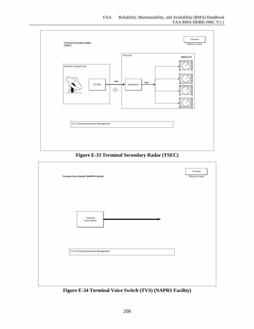
FAA Reliability, Maintainability, and Availability (RMA) Handbook
FAA RMA-HDBK-006C V1.1
208
ARTS
ARTS
ARTS
ART
S
ART
S
ARTS
ARTS
REMOTE RADAR SITE
ATCRB
3.1.2.1 Provide Separation Management
Terminal Secondary Radar
(TSEC)
TRACON
Automation
DISPLAYS
TSEC
Via
RCL//FAA
Lines
*
*
*
*
*
*
*
*
*
*
*
*
TSEC
Terminal
Efficiency-Critical
Figure E-33 Terminal Secondary Radar (TSEC)
Terminal
Voice Switch
3.1.2.1 Provide Separation Management
Terminal Voice Switch (NAPRS Facility)
Terminal
Efficiency-Critical
Figure E-34 Terminal Voice Switch (TVS) (NAPRS Facility)
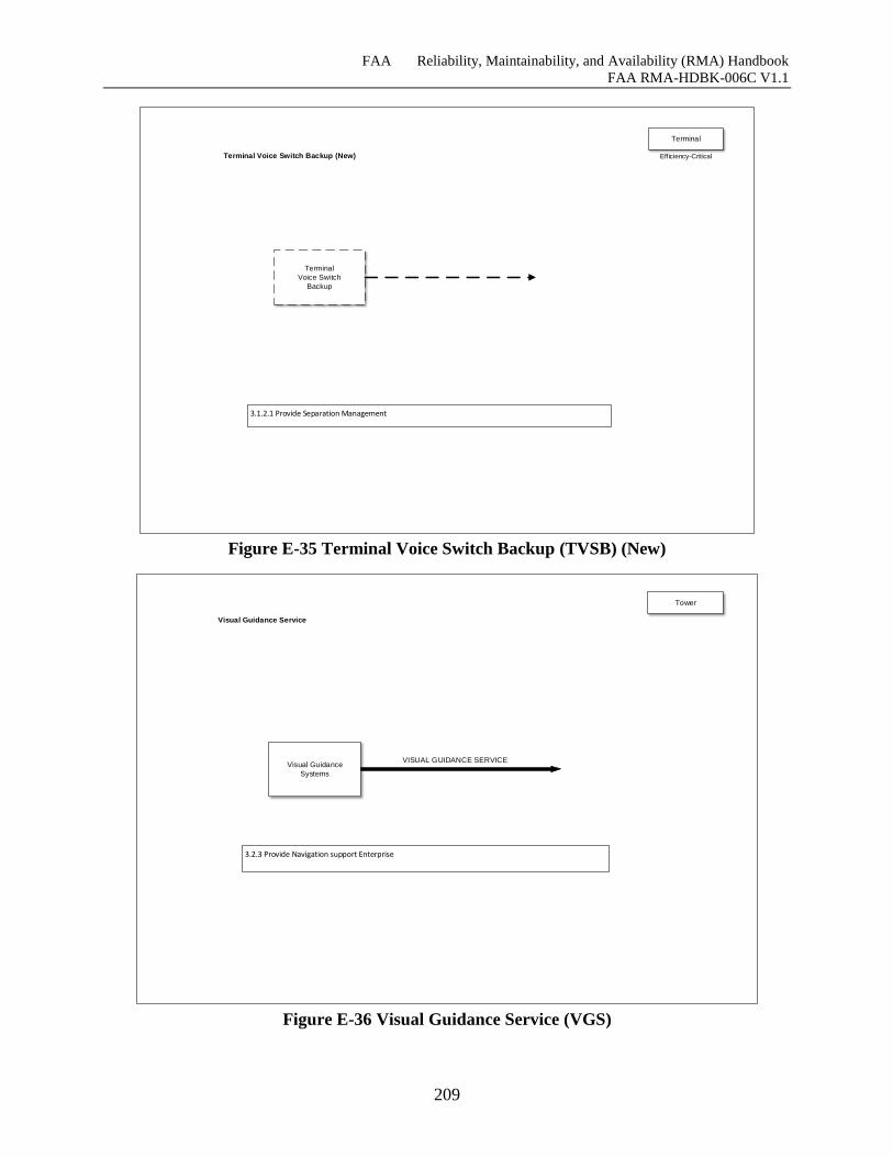
FAA Reliability, Maintainability, and Availability (RMA) Handbook
FAA RMA-HDBK-006C V1.1
209
Terminal
Voice Switch
Terminal
Voice Switch
Backup
3.1.2.1 Provide Separation Management
Terminal Voice Switch Backup (New)
Terminal
Efficiency-Critical
Figure E-35 Terminal Voice Switch Backup (TVSB) (New)
Visual Guidance
Systems
VISUAL GUIDANCE SERVICE
3.2.3 Provide Navigation support Enterprise
Visual Guidance Service
Tower
Figure E-36 Visual Guidance Service (VGS)
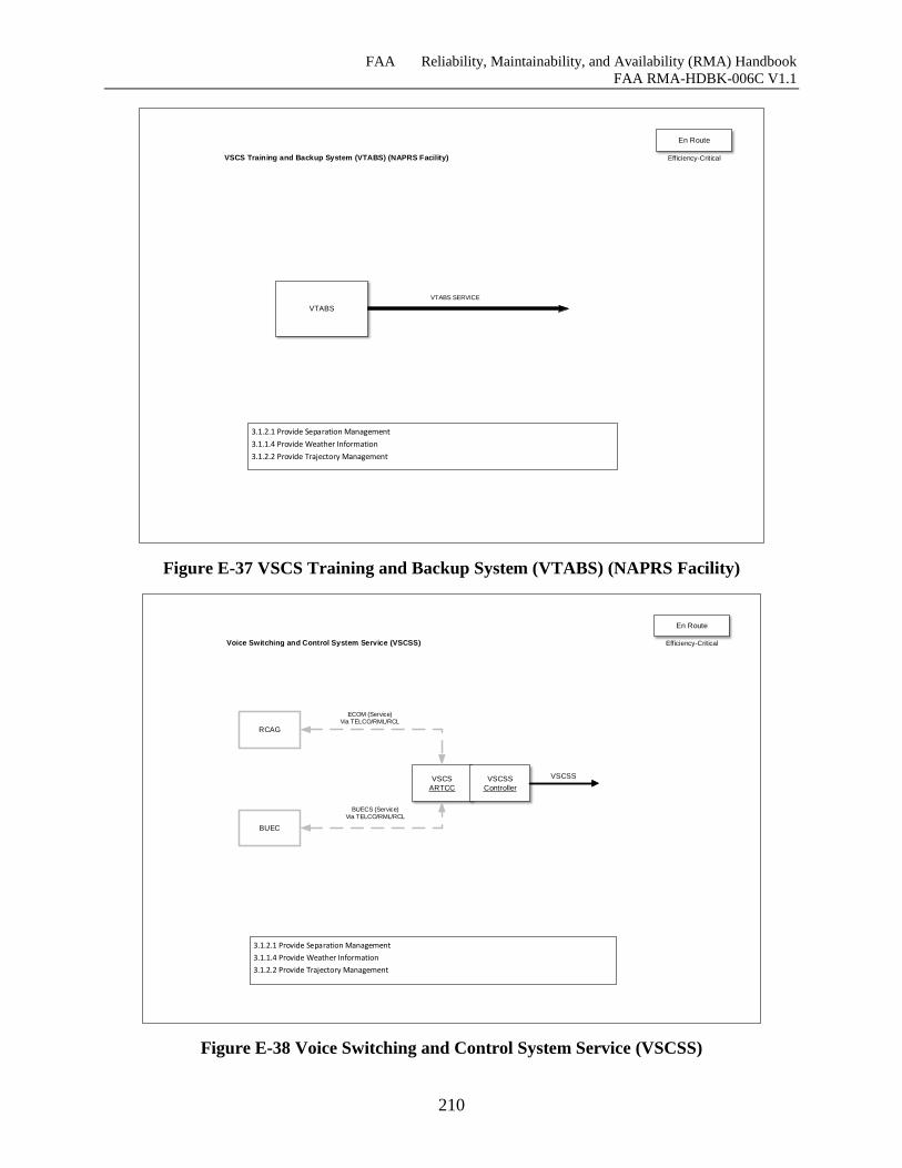
FAA Reliability, Maintainability, and Availability (RMA) Handbook
FAA RMA-HDBK-006C V1.1
210
VTABS
3.1.2.1 Provide Separation Management
3.1.1.4 Provide Weather Information
3.1.2.2 Provide Trajectory Management
VSCS Training and Backup System (VTABS) (NAPRS Facility)
VTABS SERVICE
En Route
Efficiency-Critical
Figure E-37 VSCS Training and Backup System (VTABS) (NAPRS Facility)
VSCSVSCS
ARTCC
VSCSS
Voice Switching and Control System Service (VSCSS)
VSCSS
Controller
RCAG
BUEC
BUECS (Service)Via TELCO/RML/RCL
ECOM (Service) Via TELCO/RML/RCL
3.1.2.1 Provide Separation Management
3.1.1.4 Provide Weather Information
3.1.2.2 Provide Trajectory Management
En Route
Efficiency-Critical
Figure E-38 Voice Switching and Control System Service (VSCSS)
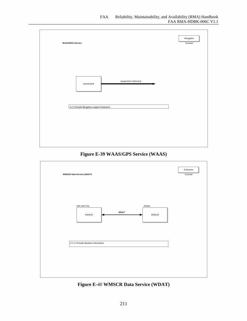
FAA Reliability, Maintainability, and Availability (RMA) Handbook
FAA RMA-HDBK-006C V1.1
211
WAAS/GPS
WAAS/GPS SERVICE
3.2.3 Provide Navigation support Enterprise
WAAS/GPS Service
Navigation
Essential
Figure E-39 WAAS/GPS Service (WAAS)
WMSCR
WDAT
3.1.1.4 Provide Weather Information
WMSCR Data Service (WDAT)
WMSCR
Salt Lake City Atlanta
Enterprise
Essential
Figure E-40 WMSCR Data Service (WDAT)
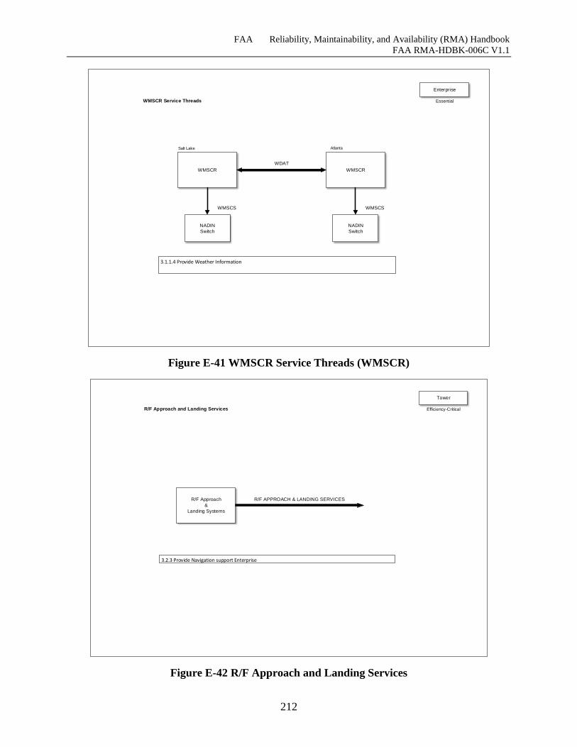
FAA Reliability, Maintainability, and Availability (RMA) Handbook
FAA RMA-HDBK-006C V1.1
212
WMSCR
WDAT
3.1.1.4 Provide Weather Information
WMSCR Service Threads
WMSCR
NADIN
Switch
NADIN
Switch
Atlanta
WMSCS
Salt Lake
WMSCS
Enterprise
Essential
Figure E-41 WMSCR Service Threads (WMSCR)
R/F Approach
&
Landing Systems
R/F APPROACH & LANDING SERVICES
3.2.3 Provide Navigation support Enterprise
R/F Approach and Landing Services
Tower
Efficiency-Critical
Figure E-42 R/F Approach and Landing Services
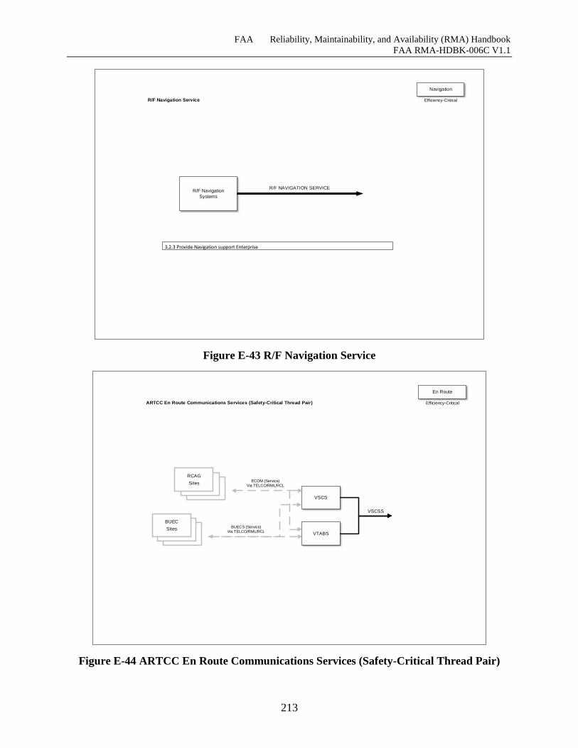
FAA Reliability, Maintainability, and Availability (RMA) Handbook
FAA RMA-HDBK-006C V1.1
213
R/F Navigation
Systems
R/F NAVIGATION SERVICE
3.2.3 Provide Navigation support Enterprise
R/F Navigation Service
Navigation
Efficiency-Critical
Figure E-43 R/F Navigation Service
VSCS
VSCS
VSCSS
ARTCC En Route Communications Services (Safety-Critical Thread Pair)
VTABS
RCAG
Sites
BUEC
SitesBUECS (Service)
Via TELCO/RML/RCL
ECOM (Service) Via TELCO/RML/RCL
En Route
Efficiency-Critical
Figure E-44 ARTCC En Route Communications Services (Safety-Critical Thread Pair)
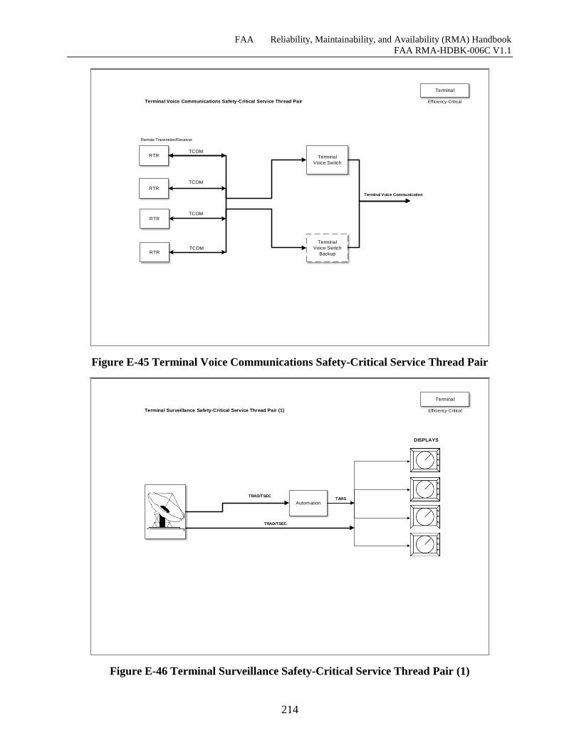
FAA Reliability, Maintainability, and Availability (RMA) Handbook
FAA RMA-HDBK-006C V1.1
214
RTR
RTR
RTR
RTR
RTR
Terminal Voice Communications Safety-Critical Service Thread Pair
RTR
RTR
RTR
RTR
Remote Transmitter/Receiver
TCOMTerminal
Voice Switch
Terminal
Voice Switch
Backup
TCOM
TCOM
TCOM
Terminal Voice Communication
Terminal
Efficiency-Critical
Figure E-45 Terminal Voice Communications Safety-Critical Service Thread Pair
ARTS
ARTS
ARTS
ARTS
ART
S
ART
S
ARTS
ARTS
Terminal Surveillance Safety-Critical Service Thread Pair (1)
Automation
DISPLAYS
TRAD/TSEC
*
*
*
*
*
*
*
*
*
*
*
*
TARS
TRAD/TSEC
Terminal
Efficiency-Critical
Figure E-46 Terminal Surveillance Safety-Critical Service Thread Pair (1)
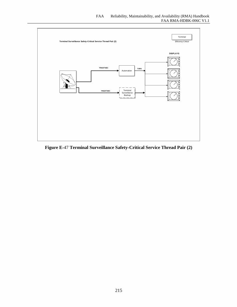
FAA Reliability, Maintainability, and Availability (RMA) Handbook
FAA RMA-HDBK-006C V1.1
215
ART
S
ARTS
ARTS
ARTS
ARTS
ART
S
ART
S
ARTS
ARTS
Terminal Surveillance Safety-Critical Service Thread Pair (2)
Automation
DISPLAYS
TRAD/TSEC
*
*
*
*
*
*
*
*
*
*
*
*
TARS
TRAD/TSEC Terminal
Surveillance
Backup
Terminal
Efficiency-Critical
Figure E-47 Terminal Surveillance Safety-Critical Service Thread Pair (2)
FAA Reliability, Maintainability, and Availability (RMA) Handbook
FAA RMA-HDBK-006C V1.1
216
EVOLUTION OF THE FAA RMA PARADIGM
The tools and techniques that are the foundation for reliability management were developed in
the late 1950’s and early 1960’s. In that timeframe, the pressures of the cold war and the space
race led to increasing complexity of electronic equipment, which in turn created reliability
problems that were exacerbated by the applications of these “equipments” in missile and space
applications that did not permit repair of failed hardware. This section examines the traditional
approaches to RMA specification and verification and describes how changes that have occurred
over the past four decades have created a need for a dramatic change in the way these RMA
issues are addressed.
F.1 The Traditional RMA Paradigm
The FAA has traditionally viewed RMA requirements in a legalistic sense. The requirements
have been part of legally binding contracts with which contractors must comply.
Because actual RMA performance can only be determined after a system is installed, a
contractor’s prospective ability to comply with RMA requirements was evaluated using the
predictions of models. Reliability predictions were based on the numbers of discrete components
used in these systems and their associated failure rates. A catalog of failure rates for standard
components was published in MIL-HDBK-217[37]. These failure rates were based on hundreds
of thousands of hours of operating time.
The predicted reliability of equipment still under development was estimated by extrapolating
from attested failure rates with adjustments reflecting the numbers and types of components used
in the new piece of equipment. If the predicted reliability was unacceptable, engineers used
various screening techniques to try to reduce the failure rates of the components. These
compensatory efforts generally increased the costs of equipment built to military specifications,
and despite efforts to improve reliability, complex electronic equipment often had MTBFs of
fewer than 1,000 hours.
To verify that electronic equipment was compliant with the specified reliability, several
preproduction models were often placed in a sealed room for a period of time. There, statistical
decision methods, as described in MIL-STD-781[38], were employed to decide whether the
requirements actually were met and the design was suitable for release to full production.
Maintainability requirements were verified by statistical techniques such as those defined in
MIL-HDBK-472 [39]. These techniques involved statistically combining component failure rates
with actually measured times to identify, remove, and replace a sample of inserted failed
components.
The military standards and handbooks that defined the statistical methods used for predicting and
verifying reliability and maintainability were based on well-established concepts that could be
found in any introductory textbook on engineering statistics.
F.2 Agents of Change
Several factors have tended to make the traditional paradigm obsolete. Among these are:
Dramatic increases in system reliability resulting both from a combination of hardware
technology advances, the use of redundancy, and application of fault tolerance
techniques.
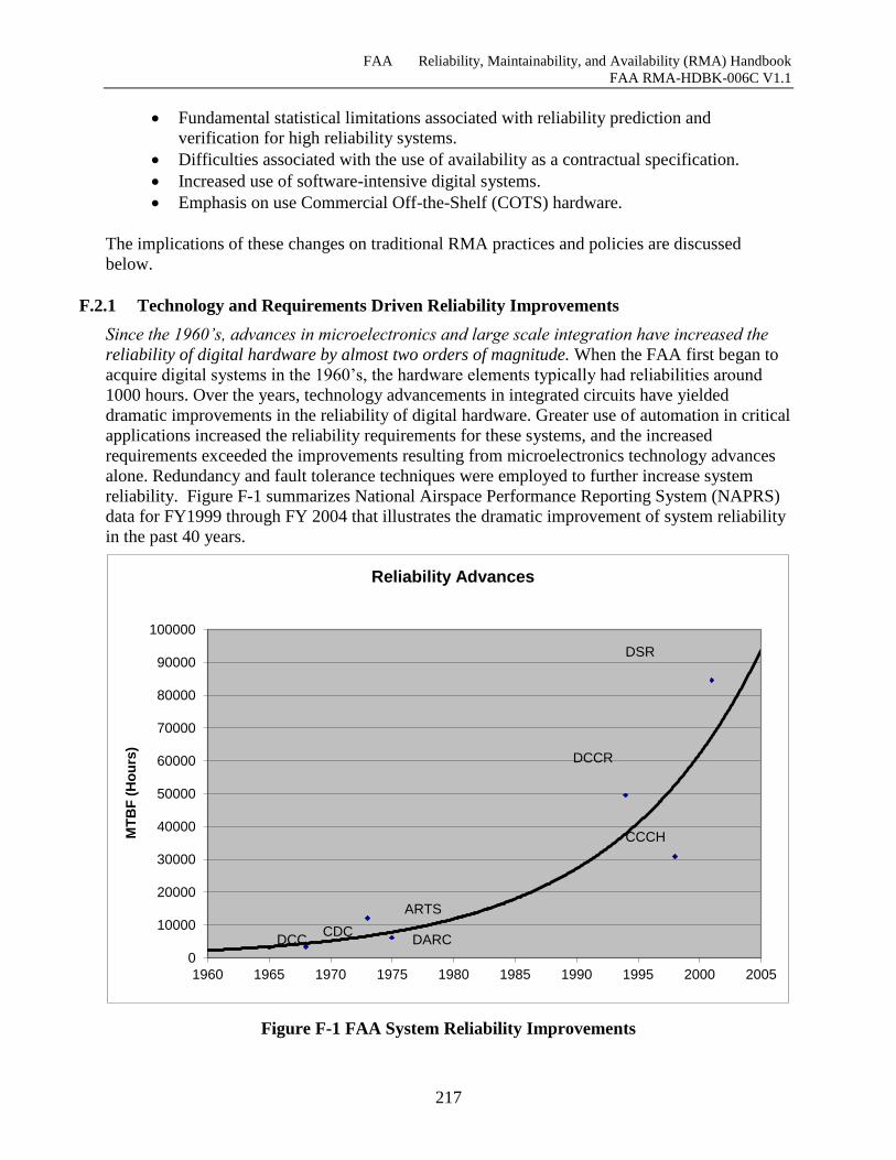
FAA Reliability, Maintainability, and Availability (RMA) Handbook
FAA RMA-HDBK-006C V1.1
217
Fundamental statistical limitations associated with reliability prediction and
verification for high reliability systems.
Difficulties associated with the use of availability as a contractual specification.
Increased use of software-intensive digital systems.
Emphasis on use Commercial Off-the-Shelf (COTS) hardware.
The implications of these changes on traditional RMA practices and policies are discussed
below.
F.2.1 Technology and Requirements Driven Reliability Improvements
Since the 1960’s, advances in microelectronics and large scale integration have increased the
reliability of digital hardware by almost two orders of magnitude. When the FAA first began to
acquire digital systems in the 1960’s, the hardware elements typically had reliabilities around
1000 hours. Over the years, technology advancements in integrated circuits have yielded
dramatic improvements in the reliability of digital hardware. Greater use of automation in critical
applications increased the reliability requirements for these systems, and the increased
requirements exceeded the improvements resulting from microelectronics technology advances
alone. Redundancy and fault tolerance techniques were employed to further increase system
reliability. Figure F-1 summarizes National Airspace Performance Reporting System (NAPRS)
data for FY1999 through FY 2004 that illustrates the dramatic improvement of system reliability
in the past 40 years.
Figure F-1 FAA System Reliability Improvements
0
10000
20000
30000
40000
50000
60000
70000
80000
90000
100000
1960 1965 1970 1975 1980 1985 1990 1995 2000 2005
MT
BF
(H
ou
rs)
Reliability Advances
DSR
DCCR
CCCH
DARC
ARTS
CDCDCC
FAA Reliability, Maintainability, and Availability (RMA) Handbook
FAA RMA-HDBK-006C V1.1
218
F.2.2 Fundamentals Statistical Limitations
Since statistical methods were first applied to RMA modeling, allocation, prediction, and
verification, there has been an exponential growth in the reliability of digital hardware. There has
also been a related growth in demand for higher reliability in systems for use in critical ATC
applications. This exponential growth in the reliability of FAA systems has certainly benefited
their users, but it also has created significant challenges to those who specify, predict, and verify
the RMA characteristics of these systems. Conventional statistical methods, those that have
traditionally been used for these purposes, simply do not scale well to high levels of reliability.
F.2.2.1 Reliability Modeling
Forty years ago, the use of digital computers to process surveillance data and other important
real-time and near-real-time operations created a demand for more reliable systems. When the
FAA began to acquire NAS En Route Stage A in the early 1960’s, the IBM 360 series computer
elements that were used in the Central Computer Complex had an MTBF on the order of 1000
hours, and the combined MTBF of all of the elements in the Central Computer Complex (CCC)
was predicted to be approximately 60 hours. In contrast, the required reliability for the NAS
Stage A CCC was 10,000 hours. The FAA and IBM had to try to achieve this unheard of level of
reliability with hardware elements whose reliability was an order of magnitude less than the
requirement. They found a way. Together, the FAA and the researchers pioneered the use of
redundancy and automatic fault detection and recovery techniques.
The reliability of the CCC was predicted using a set of Markov-based combinatorial equations
developed by S. J. Einhorn in 1963. Drawing on the MTBF and MTTR together with the amount
of redundancy, the equations predicted the reliability of repairable redundant configurations of
identical elements. They modeled the average time taken from the depletion of spares, with
resulting failures, and the return to service of failed elements. Einhorn’s equations were based
solely on the combinatorial probability of running out of spare elements and assumed perfect
fault coverage, perfect software, and perfect switchover. They did not address the effectiveness
of the automatic fault detection and recovery mechanisms or the effect of software failures on the
predicted MTBF.
A simple sensitivity analysis of the effectiveness parameter for automatic fault detection and
recovery mechanisms yielded a graph such as the one shown in Figure F-2. At 100%
effectiveness the CCC 10,000 hour reliability requirement is exceeded by 50%. At 0%
effectiveness, the predicted CCC reliability would be 60 hours. The true MTBF lies somewhere
in between, but the reliability falls so quickly when the fault detection and recovery effectiveness
is less than perfect, that it is virtually impossible to predict it with enough accuracy to be useful.
Developers included fault handling provisions for all known failure classes in an attempt to
achieve 100% effectiveness, but they knew that without access to the number of unknown failure
modes they were unlikely to reach this goal.22
The models used to predict reliability for fault-tolerant systems were so sensitive to the
effectiveness parameter for the fault tolerance mechanisms that their predictions had little
22Note: as reliability models became more sophisticated and computerized, this parameter became known as
“coverage,” the probability that recovery from a failure will be successful, given that a failure has occurred. The
concepts and underlying mathematics for reliability and availability models is discussed in greater detail in
Appendix C.
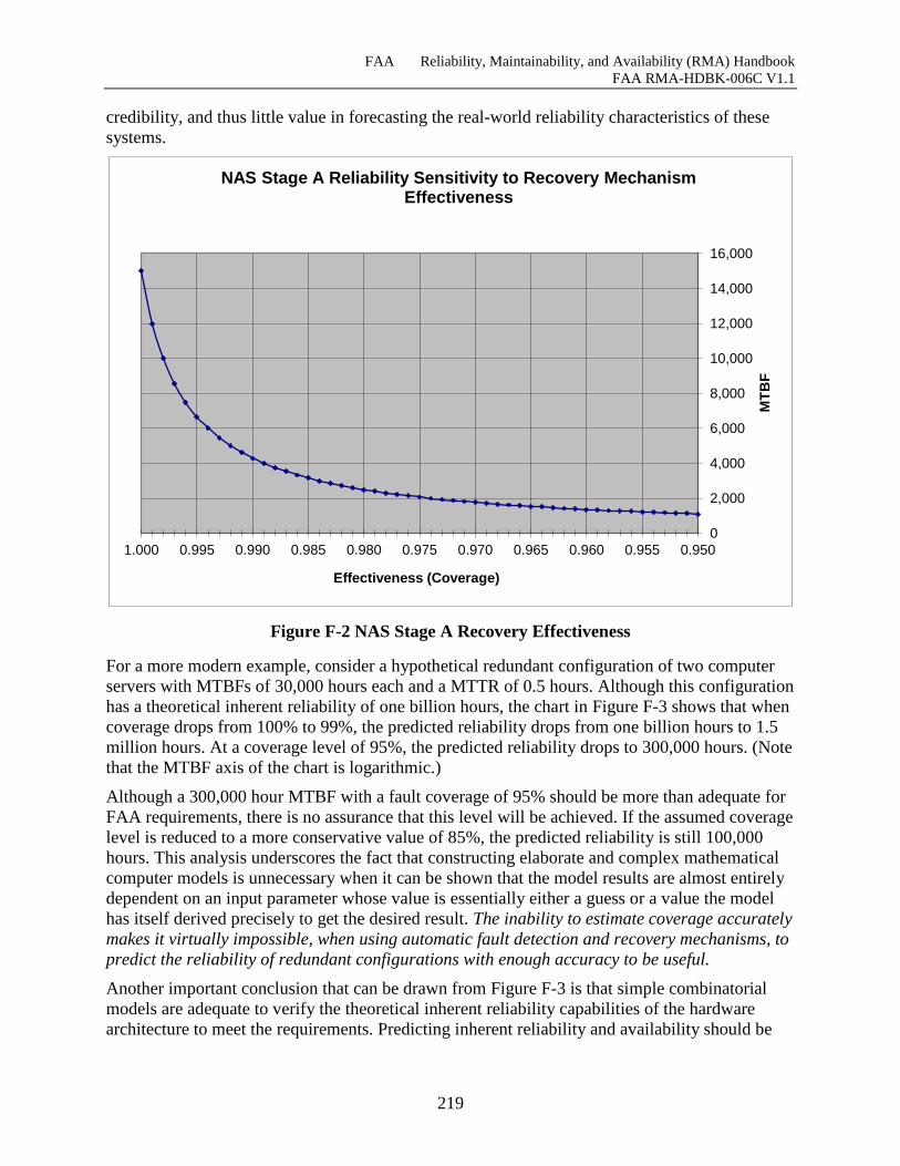
FAA Reliability, Maintainability, and Availability (RMA) Handbook
FAA RMA-HDBK-006C V1.1
219
credibility, and thus little value in forecasting the real-world reliability characteristics of these
systems.
Figure F-2 NAS Stage A Recovery Effectiveness
For a more modern example, consider a hypothetical redundant configuration of two computer
servers with MTBFs of 30,000 hours each and a MTTR of 0.5 hours. Although this configuration
has a theoretical inherent reliability of one billion hours, the chart in Figure F-3 shows that when
coverage drops from 100% to 99%, the predicted reliability drops from one billion hours to 1.5
million hours. At a coverage level of 95%, the predicted reliability drops to 300,000 hours. (Note
that the MTBF axis of the chart is logarithmic.)
Although a 300,000 hour MTBF with a fault coverage of 95% should be more than adequate for
FAA requirements, there is no assurance that this level will be achieved. If the assumed coverage
level is reduced to a more conservative value of 85%, the predicted reliability is still 100,000
hours. This analysis underscores the fact that constructing elaborate and complex mathematical
computer models is unnecessary when it can be shown that the model results are almost entirely
dependent on an input parameter whose value is essentially either a guess or a value the model
has itself derived precisely to get the desired result. The inability to estimate coverage accurately
makes it virtually impossible, when using automatic fault detection and recovery mechanisms, to
predict the reliability of redundant configurations with enough accuracy to be useful.
Another important conclusion that can be drawn from Figure F-3 is that simple combinatorial
models are adequate to verify the theoretical inherent reliability capabilities of the hardware
architecture to meet the requirements. Predicting inherent reliability and availability should be
0
2,000
4,000
6,000
8,000
10,000
12,000
14,000
16,000
0.9500.9550.9600.9650.9700.9750.9800.9850.9900.9951.000
MT
BF
Effectiveness (Coverage)
NAS Stage A Reliability Sensitivity to Recovery Mechanism Effectiveness
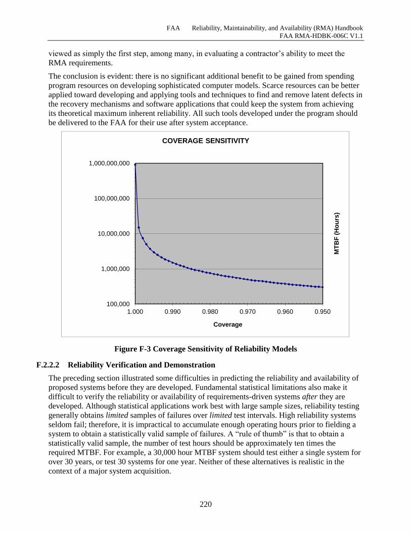
FAA Reliability, Maintainability, and Availability (RMA) Handbook
FAA RMA-HDBK-006C V1.1
220
viewed as simply the first step, among many, in evaluating a contractor’s ability to meet the
RMA requirements.
The conclusion is evident: there is no significant additional benefit to be gained from spending
program resources on developing sophisticated computer models. Scarce resources can be better
applied toward developing and applying tools and techniques to find and remove latent defects in
the recovery mechanisms and software applications that could keep the system from achieving
its theoretical maximum inherent reliability. All such tools developed under the program should
be delivered to the FAA for their use after system acceptance.
Figure F-3 Coverage Sensitivity of Reliability Models
F.2.2.2 Reliability Verification and Demonstration
The preceding section illustrated some difficulties in predicting the reliability and availability of
proposed systems before they are developed. Fundamental statistical limitations also make it
difficult to verify the reliability or availability of requirements-driven systems after they are
developed. Although statistical applications work best with large sample sizes, reliability testing
generally obtains limited samples of failures over limited test intervals. High reliability systems
seldom fail; therefore, it is impractical to accumulate enough operating hours prior to fielding a
system to obtain a statistically valid sample of failures. A “rule of thumb” is that to obtain a
statistically valid sample, the number of test hours should be approximately ten times the
required MTBF. For example, a 30,000 hour MTBF system should test either a single system for
over 30 years, or test 30 systems for one year. Neither of these alternatives is realistic in the
context of a major system acquisition.
100,000
1,000,000
10,000,000
100,000,000
1,000,000,000
0.9500.9600.9700.9800.9901.000
MT
BF
(H
ou
rs)
Coverage
COVERAGE SENSITIVITY
FAA Reliability, Maintainability, and Availability (RMA) Handbook
FAA RMA-HDBK-006C V1.1
221
Several quantitative parameters are used to describe the characteristics of a formal reliability
qualification test, including confidence intervals, producer’s risk, consumer’s risk, and
discrimination ratio. The end result, however, is that – when an accept/reject decision is based on
inadequate test time – there is a significant probability of either accepting a system that does not
meet the requirements (consumer’s risk), or of rejecting a system that does, in fact, meet the
requirements (producer’s risk).23
Arguments underlying these decisions are based strictly on conventional text-book statistics
theory. They fail to address the practical reality that modern software systems are not suited to
evaluation by fixed reliability qualification tests alone. Today’s software is dynamic and
adaptive. Enhancements, program trouble reports, patches, and the like present an ever-changing
reality that must be effectively managed. The only practical alternative, in today’s world, is to
pursue an aggressive reliability growth program and deploy a system to the field only when a
new version of a system can be shown to be more stable than the system it will replace. Formal
reliability demonstration programs, such as those used for the electronic “black boxes” of the
past, are no longer feasible for modern automation systems.
F.2.3 Use of Availability as a Conceptual Specification
For the last twenty years, FAA specifications have focused primarily on availability
requirements in place of the more traditional reliability and maintainability requirements that
preceded them. Availability requirements are useful at the highest levels of management. They
provide a quantitative and consistent way of summarizing the need for continuity of NAS
Services. They can facilitate the comparison and assessment of architectural alternatives by
FAA headquarters system engineering personnel. They also bring a useful performance metric to
analyses of operationally deployed systems and Life Cycle Cost tradeoffs. And, because
availability includes all sources of downtime and reflects the perspective of system users, it is a
good overall operational performance measure of the performance of fielded systems.
There are, however, significant problems with employing availability as a primary RMA
requirement in contractual specifications. This operational performance measure combines
equipment reliability and maintainability characteristics with operation and maintenance factors
that are beyond the control of the contractor as well as outside of the temporal scope of the
contract.
The fundamental concept of availability implies that reliability and maintainability can be traded
off. In other words, a one-hour interruption of a critical service that occurs annually is seen as
equivalent to a 15-second interruption of the same service that occurs every couple of days ―
both scenarios provide approximately the same availability. It should be obvious that
interruptions lasting a few seconds are unlikely to have a major impact on ATC operations, while
interruptions lasting an hour or more have the potential to significantly impact traffic flow and
safety of operations. Contractors should not be permitted, however, to trade off reliability and
maintainability arbitrarily to achieve a specific availability goal. Such tradeoffs have the
potential to adversely impact NAS operations. They also allow a readily measured parameter
such as recovery time to be traded off against an unrealistic and immeasurable reliability
requirement following a logic such as: “It may take two hours to recover from a failure, but it
23 The basic mathematics underlying these effects is summarized in Appendix D. For a more detailed discussion of reliability
qualification testing, see MIL-STD-781[38].
FAA Reliability, Maintainability, and Availability (RMA) Handbook
FAA RMA-HDBK-006C V1.1
222
will be 20,000,000 hours between failures, so the availability is still acceptable, i.e., seven
‘nines.’
As pointed out above, during system development, availability can only be predicted using
highly artificial models. Following development, system availability is not easily measured
during testing at the WJHTC. The fundamental statistical sampling limitations associated with
high levels of reliability and availability are not the only problem. Availability cannot be
measured directly; it can only be calculated from measurements of system downtime and the
total operating time.
Deciding how much of the downtime associated with a failure should be included or excluded
from calculations of availability is difficult and contentious. In an operational environment,
matters are clear cut: simply dividing the time that a system is operational by the total calendar
time yields the availability. In a test environment, however, adjustments are required for
downtimes caused by things like administrative delays, lack of spares, and the like – factors that
the contractor cannot control. Failure review boards are faced with the highly subjective process
of deciding which failures are relevant and how much of the associated downtime to include.
For these reasons, the FAA needs to establish specifications that can be more readily monitored
during development and measured at the contractor’s plant and the WJHTC prior to acceptance
of the system.
F.2.4 RMA Issues for Software-Intensive Systems
The contribution of hardware failures to the overall system reliability for a software-intensive
system is generally negligible. Software reliability, i.e., the presence of latent design defects
(faults), is by far the dominant factor in the overall reliability of these systems. Most models that
predict software reliability rely on historical data of the numbers of latent defects per thousand
source lines of code (at various stages of development) to discover and recommend the removal
of latent software defects. These models may be useful for estimating test time, manpower and
costs to reduce the fault density to acceptable levels; but they provide no reliable insight into the
run-time behavior of the software or the predicted operational reliability of the system.
Although some academic papers have attempted to develop models that can relate fault density
to the run-time behavior of software, the accuracy and usefulness of these models is questionable
and unproven. Again, the fundamental problem in predicting software reliability is the need to
predict, with some degree of certainty, how frequently each latent fault in the code is likely to
result in an operational failure. Essentially, this is a function of how often a particular section of
code is executed. For routines such as surveillance processing that are scheduled at regular
intervals, this is perhaps feasible. Other areas of code, however, may only be executed rarely. For
a complex system containing a million or more lines of code, with various frequencies of
occurrence, the prediction problem becomes intractable.
F.2.4.1 Software Reliability Characteristics
Unlike Hardware Reliability, Software Reliability is not a direct function of time. Hardware parts
may age and wear out with time and usage, but software is not a prone to directly effects of
physical forces like wear-out during its life cycle. Software will not change over time unless
there is direct intervention to intentionally change or upgrade it. [1]
FAA Reliability, Maintainability, and Availability (RMA) Handbook
FAA RMA-HDBK-006C V1.1
223
Software Reliability is an important attribute of software quality, together with functionality,
usability, performance, serviceability, capability, install-ability, maintainability, and
documentation. Software Reliability is hard to achieve, because the complexity of software tends
to be high. With any system having a high degree of complexity, including software, it will be
hard to reach a certain level of reliability. System developers tend to push complexity into the
software layer, given the rapid growth of system size and ease of doing so by upgrading the
software.
For example, NextGen Air Traffic Control (ATC) systems will contain between one and two
million lines of code. [4] While the complexity of software is inversely related to software
reliability, it is directly related to other important factors in software quality, especially
functionality, capability, etc. Emphasizing these features will tend to add more complexity to
software. [1]
Some of the distinct characteristics of software compared to hardware are listed below [6]:
Failure cause – Software defects are mainly design defects
Wear-out – Software does not have energy related wear-out phase. Errors can occur
without warning.
Repairable System Concept – Periodic restarts can help fix software problems.
Time Dependency and Life Cycle – Software reliability is not a function of
operational time.
Environmental Factors – Do not affect software reliability, except it might affect
program inputs.
Reliability Prediction – Software reliability cannot be predicted from any physical
basis, since it depends completely on human factors in design.
Redundancy – Cannot improve software reliability if identical software components
are used.
Interfaces – Software interfaces are purely conceptual other than visual.
Failure Rate Motivators – Usually not predictable from analyses of separate
statements.
Built with Standard Components – Well-understood and extensively-tested
standard parts will help improve maintainability and reliability. But in software
industry, this trend has not been observed for the most part. Code reuse has been
around for some time, but to a very limited extent.
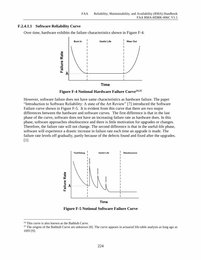
FAA Reliability, Maintainability, and Availability (RMA) Handbook
FAA RMA-HDBK-006C V1.1
224
F.2.4.1.1 Software Reliability Curve
Over time, hardware exhibits the failure characteristics shown in Figure F-4.
Figure F-4 Notional Hardware Failure Curve24,25
However, software failure does not have same characteristics as hardware failure. The paper
“Introduction to Software Reliability: A state of the Art Review” [7] introduced the Software
Failure curve shown in Figure F-5. It is evident from this curve that there are two major
differences between the hardware and software curves. The first difference is that in the last
phase of the curve, software does not have an increasing failure rate as hardware does. In this
phase, software approaches obsolescence and there is little motivation for upgrades or changes.
Therefore, the failure rate will not change. The second difference is that in the useful-life phase,
software will experience a drastic increase in failure rate each time an upgrade is made. The
failure rate levels off gradually, partly because of the defects found and fixed after the upgrades.
[1]
Figure F-5 Notional Software Failure Curve
24 This curve is also known as the Bathtub Curve. 25 The origins of the Bathtub Curve are unknown [8]. The curve appears in actuarial life-table analysis as long ago as
1693 [9].
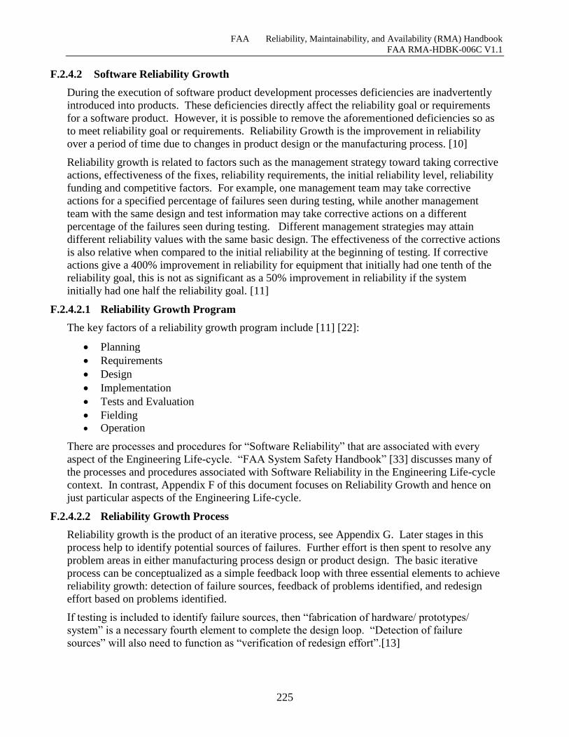
FAA Reliability, Maintainability, and Availability (RMA) Handbook
FAA RMA-HDBK-006C V1.1
225
F.2.4.2 Software Reliability Growth
During the execution of software product development processes deficiencies are inadvertently
introduced into products. These deficiencies directly affect the reliability goal or requirements
for a software product. However, it is possible to remove the aforementioned deficiencies so as
to meet reliability goal or requirements. Reliability Growth is the improvement in reliability
over a period of time due to changes in product design or the manufacturing process. [10]
Reliability growth is related to factors such as the management strategy toward taking corrective
actions, effectiveness of the fixes, reliability requirements, the initial reliability level, reliability
funding and competitive factors. For example, one management team may take corrective
actions for a specified percentage of failures seen during testing, while another management
team with the same design and test information may take corrective actions on a different
percentage of the failures seen during testing. Different management strategies may attain
different reliability values with the same basic design. The effectiveness of the corrective actions
is also relative when compared to the initial reliability at the beginning of testing. If corrective
actions give a 400% improvement in reliability for equipment that initially had one tenth of the
reliability goal, this is not as significant as a 50% improvement in reliability if the system
initially had one half the reliability goal. [11]
F.2.4.2.1 Reliability Growth Program
The key factors of a reliability growth program include [11] [22]:
Planning
Requirements
Design
Implementation
Tests and Evaluation
Fielding
Operation
There are processes and procedures for “Software Reliability” that are associated with every
aspect of the Engineering Life-cycle. “FAA System Safety Handbook” [33] discusses many of
the processes and procedures associated with Software Reliability in the Engineering Life-cycle
context. In contrast, Appendix F of this document focuses on Reliability Growth and hence on
just particular aspects of the Engineering Life-cycle.
F.2.4.2.2 Reliability Growth Process
Reliability growth is the product of an iterative process, see Appendix G. Later stages in this
process help to identify potential sources of failures. Further effort is then spent to resolve any
problem areas in either manufacturing process design or product design. The basic iterative
process can be conceptualized as a simple feedback loop with three essential elements to achieve
reliability growth: detection of failure sources, feedback of problems identified, and redesign
effort based on problems identified.
If testing is included to identify failure sources, then “fabrication of hardware/ prototypes/
system” is a necessary fourth element to complete the design loop. “Detection of failure
sources” will also need to function as “verification of redesign effort”.[13]
FAA Reliability, Maintainability, and Availability (RMA) Handbook
FAA RMA-HDBK-006C V1.1
226
Figure F-6 Notional Reliability Growth Management26
F.2.5 RMA Considerations for Systems Using COTS or NDI Hardware Elements
Given the pressure to justify the costs of new systems, there is a strong desire to use COTS
hardware as an alternative to custom-developed hardware for FAA systems. This means that the
Government is unlikely to be able to exercise control over the internal design characteristics of
the basic hardware elements used to construct systems. Both the reliability and maintainability of
the elements are predetermined and largely beyond the control of the FAA. The only real option
is to require field data to substantiate a contractor’s claims for the reliability and maintainability
of the COTS products. The FAA’s ability to influence the design of systems employing
COTS/NDI components is primarily limited to demanding the removal and replacement of some
unwanted hardware elements from their mountings, and possibly to requiring that hardware be
built to industrial, instead of commercial standards
26 See [16].
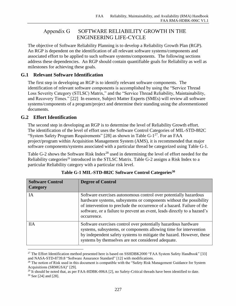
FAA Reliability, Maintainability, and Availability (RMA) Handbook
FAA RMA-HDBK-006C V1.1
227
SOFTWARE RELIABILITY GROWTH IN THE
ENGINEERING LIFE-CYCLE
The objective of Software Reliability Planning is to develop a Reliability Growth Plan (RGP).
An RGP is dependent on the identification of all relevant software systems/components and
associated effort to be applied to such software systems/components. The following sections
address these dependencies. An RGP should contain quantifiable goals for Reliability as well as
milestones for achieving these goals.
G.1 Relevant Software Identification
The first step in developing an RGP is to identify relevant software components. The
identification of relevant software components is accomplished by using the “Service Thread
Loss Severity Category (STLSC) Matrix,” and the “Service Thread Reliability, Maintainability,
and Recovery Times.” [22] In essence, Subject Matter Experts (SMEs) will review all software
systems/components of a program/project and determine their standing using the aforementioned
documents.
G.2 Effort Identification
The second step in developing an RGP is to determine the level of Reliability Growth effort.
The identification of the level of effort uses the Software Control Categories of MIL-STD-882C
“System Safety Program Requirements” [28] as shown in Table G-127. For an FAA
project/program within Acquisition Management System (AMS), it is recommended that major
software components/systems associated with a particular thread be categorized using Table G-1.
Table G-2 shows the Software Risk Index28 used in determining the level of effort needed for the
Reliability categories29 introduced in the STLSC Matrix. Table G-2 assigns a Risk Index to a
particular Reliability category with a particular risk level.
Table G-1 MIL-STD-882C Software Control Categories30
Software Control
Category
Degree of Control
IA Software exercises autonomous control over potentially hazardous
hardware systems, subsystems or components without the possibility
of intervention to preclude the occurrence of a hazard. Failure of the
software, or a failure to prevent an event, leads directly to a hazard’s
occurrence.
IIA Software exercises control over potentially hazardous hardware
systems, subsystems, or components allowing time for intervention
by independent safety systems to mitigate the hazard. However, these
systems by themselves are not considered adequate.
27 The Effort Identification method presented here is based on SSHDBK2000 “FAA System Safety Handbook” [33]
and NASA-STD-8739.8 “Software Assurance Standard” [12] with modifications. 28 The notion of Risk used in this document is compatible with the “Safety Risk Management Guidance for System
Acquisitions (SRMGSA)" [29]. 29 It should be noted that, as per FAA-HDBK-006A [2], no Safety-Critical threads have been identified to date. 30 See [24] and [28].
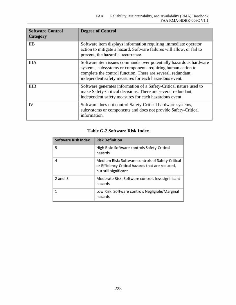
FAA Reliability, Maintainability, and Availability (RMA) Handbook
FAA RMA-HDBK-006C V1.1
228
Software Control
Category
Degree of Control
IIB Software item displays information requiring immediate operator
action to mitigate a hazard. Software failures will allow, or fail to
prevent, the hazard’s occurrence.
IIIA Software item issues commands over potentially hazardous hardware
systems, subsystems or components requiring human action to
complete the control function. There are several, redundant,
independent safety measures for each hazardous event.
IIIB Software generates information of a Safety-Critical nature used to
make Safety-Critical decisions. There are several redundant,
independent safety measures for each hazardous event.
IV Software does not control Safety-Critical hardware systems,
subsystems or components and does not provide Safety-Critical
information.
Table G-2 Software Risk Index
Software Risk Index Risk Definition
5 High Risk: Software controls Safety-Critical hazards
4 Medium Risk: Software controls of Safety-Critical or Efficiency-Critical hazards that are reduced, but still significant
2 and 3 Moderate Risk: Software controls less significant hazards
1 Low Risk: Software controls Negligible/Marginal hazards
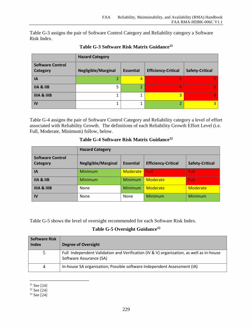
FAA Reliability, Maintainability, and Availability (RMA) Handbook
FAA RMA-HDBK-006C V1.1
229
Table G-3 assigns the pair of Software Control Category and Reliability category a Software
Risk Index.
Table G-3 Software Risk Matrix Guidance31
Hazard Category
Software Control Category Negligible/Marginal Essential Efficiency-Critical Safety-Critical
IA 2 4 5 5
IIA & IIB 5 2 4 5
IIIA & IIIB 1 1 3 4
IV 1 1 2 3
Table G-4 assigns the pair of Software Control Category and Reliability category a level of effort
associated with Reliability Growth. The definitions of each Reliability Growth Effort Level (i.e.
Full, Moderate, Minimum) follow, below.
Table G-4 Software Risk Matrix Guidance32
Hazard Category
Software Control Category Negligible/Marginal Essential Efficiency-Critical Safety-Critical
IA Minimum Moderate Full Full
IIA & IIB Minimum Minimum Moderate Full
IIIA & IIIB None Minimum Moderate Moderate
IV None None Minimum Minimum
Table G-5 shows the level of oversight recommended for each Software Risk Index.
Table G-5 Oversight Guidance33
Software Risk Index Degree of Oversight
5 Full Independent Validation and Verification (IV & V) organization, as well as in-house Software Assurance (SA)
4 In-house SA organization; Possible software Independent Assessment (IA)
31 See [24] 32 See [24] 33 See [24]
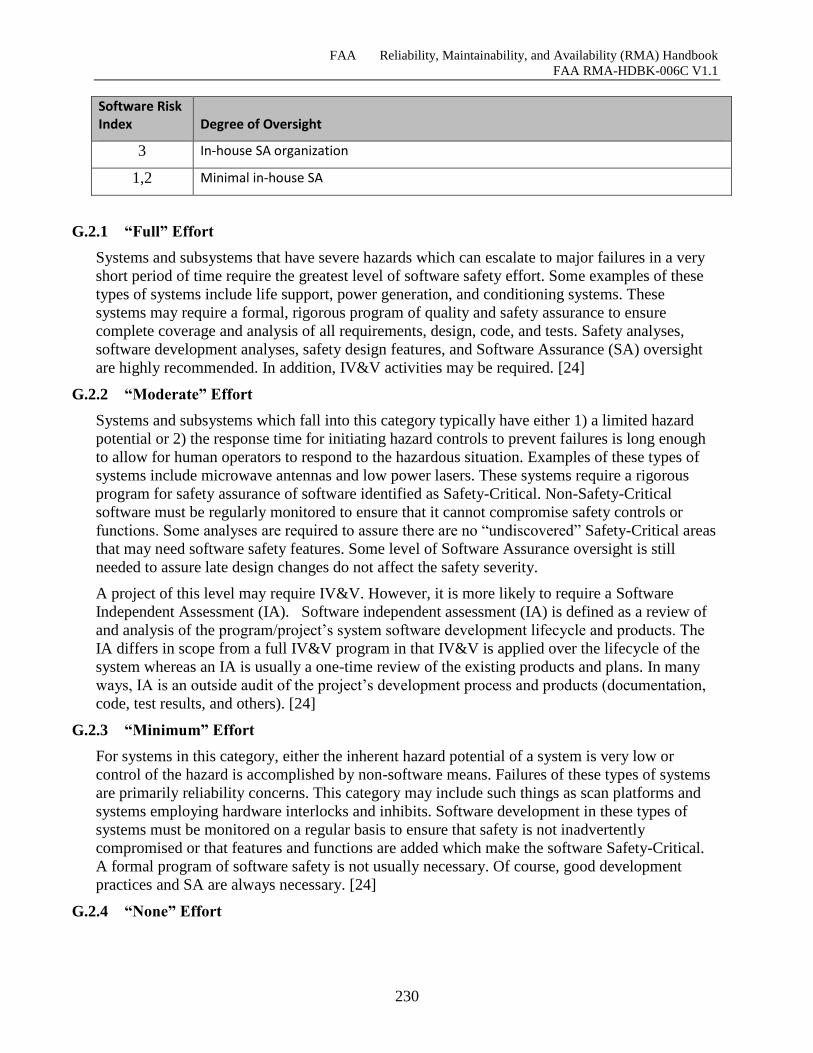
FAA Reliability, Maintainability, and Availability (RMA) Handbook
FAA RMA-HDBK-006C V1.1
230
Software Risk Index Degree of Oversight
3 In-house SA organization
1,2 Minimal in-house SA
G.2.1 “Full” Effort
Systems and subsystems that have severe hazards which can escalate to major failures in a very
short period of time require the greatest level of software safety effort. Some examples of these
types of systems include life support, power generation, and conditioning systems. These
systems may require a formal, rigorous program of quality and safety assurance to ensure
complete coverage and analysis of all requirements, design, code, and tests. Safety analyses,
software development analyses, safety design features, and Software Assurance (SA) oversight
are highly recommended. In addition, IV&V activities may be required. [24]
G.2.2 “Moderate” Effort
Systems and subsystems which fall into this category typically have either 1) a limited hazard
potential or 2) the response time for initiating hazard controls to prevent failures is long enough
to allow for human operators to respond to the hazardous situation. Examples of these types of
systems include microwave antennas and low power lasers. These systems require a rigorous
program for safety assurance of software identified as Safety-Critical. Non-Safety-Critical
software must be regularly monitored to ensure that it cannot compromise safety controls or
functions. Some analyses are required to assure there are no “undiscovered” Safety-Critical areas
that may need software safety features. Some level of Software Assurance oversight is still
needed to assure late design changes do not affect the safety severity.
A project of this level may require IV&V. However, it is more likely to require a Software
Independent Assessment (IA). Software independent assessment (IA) is defined as a review of
and analysis of the program/project’s system software development lifecycle and products. The
IA differs in scope from a full IV&V program in that IV&V is applied over the lifecycle of the
system whereas an IA is usually a one-time review of the existing products and plans. In many
ways, IA is an outside audit of the project’s development process and products (documentation,
code, test results, and others). [24]
G.2.3 “Minimum” Effort
For systems in this category, either the inherent hazard potential of a system is very low or
control of the hazard is accomplished by non-software means. Failures of these types of systems
are primarily reliability concerns. This category may include such things as scan platforms and
systems employing hardware interlocks and inhibits. Software development in these types of
systems must be monitored on a regular basis to ensure that safety is not inadvertently
compromised or that features and functions are added which make the software Safety-Critical.
A formal program of software safety is not usually necessary. Of course, good development
practices and SA are always necessary. [24]
G.2.4 “None” Effort
FAA Reliability, Maintainability, and Availability (RMA) Handbook
FAA RMA-HDBK-006C V1.1
231
This category implies that no efforts specific to Software Reliablity are needed for software
associated with a particular thread. This does not mean that best practices for software
development should be bypassed. Rather, this means only that specific efforts to increase
Software Reliability are not needed because software is not associated with Safety-Critical
applications. However, a program/project manager may still choose to use some of the processes
associated with Software Relaiability Growth since these processes are general and not
necessarily only related with Software Reliability Growth. For example, Change Management is
a good practice in general for all software development independent of whether the software is
associated with Safety-Critical applications.
G.3 Goals Guidance
Table G-6 below details all applicable methods/processes form all phases of the Engineering
Life-cycle that a program/project manager needs to keep in mind while planning for reliability
growth. Table G-6 also includes a Cost/Benefit analysis and specific effort guidance for these
methods/processes. Finally, Table G-6 below also includes a classification of the type of
methods/process. It should be noticed that Table G-6 Method/Process items that are further
decomposed contain roll-ups of the approximate average for Cost Rating, Benefit Rating, Effort,
and Task Type of sub-components. Table G-7 contains miscellaneous notes and references for
specific Software Reliability methods/processes that are useful in reliability planning.
Table G-6 and Table G-7 should be used in determining the goals of an RGP. In essence, the
product of using these tables will be a list of processes to be applied during the Engineering Life-
cycle. The lists of processes along with associated milestones specify the goals in an RGP.
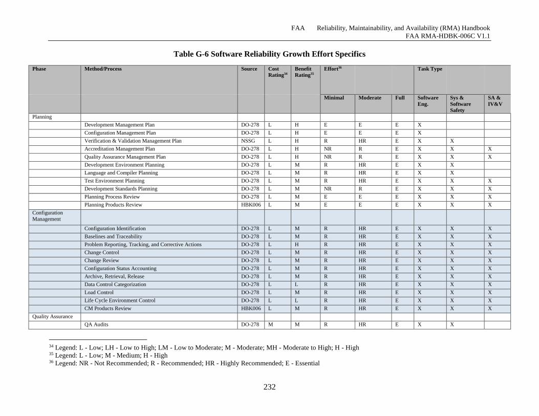
FAA Reliability, Maintainability, and Availability (RMA) Handbook
FAA RMA-HDBK-006C V1.1
232
Table G-6 Software Reliability Growth Effort Specifics
Phase Method/Process Source Cost
Rating34
Benefit
Rating35
Effort36 Task Type
Minimal Moderate Full Software
Eng.
Sys &
Software
Safety
SA &
IV&V
Planning
Development Management Plan DO-278 L H E E E X
Configuration Management Plan DO-278 L H E E E X
Verification & Validation Management Plan NSSG L H R HR E X X
Accreditation Management Plan DO-278 L H NR R E X X X
Quality Assurance Management Plan DO-278 L H NR R E X X X
Development Environment Planning DO-278 L M R HR E X X
Language and Compiler Planning DO-278 L M R HR E X X
Test Environment Planning DO-278 L M R HR E X X X
Development Standards Planning DO-278 L M NR R E X X X
Planning Process Review DO-278 L M E E E X X X
Planning Products Review HBK006 L M E E E X X X
Configuration
Management
Configuration Identification DO-278 L M R HR E X X X
Baselines and Traceability DO-278 L M R HR E X X X
Problem Reporting, Tracking, and Corrective Actions DO-278 L H R HR E X X X
Change Control DO-278 L M R HR E X X X
Change Review DO-278 L M R HR E X X X
Configuration Status Accounting DO-278 L M R HR E X X X
Archive, Retrieval, Release DO-278 L M R HR E X X X
Data Control Categorization DO-278 L L R HR E X X X
Load Control DO-278 L M R HR E X X X
Life Cycle Environment Control DO-278 L L R HR E X X X
CM Products Review HBK006 L M R HR E X X X
Quality Assurance
QA Audits DO-278 M M R HR E X X
34 Legend: L - Low; LH - Low to High; LM - Low to Moderate; M - Moderate; MH - Moderate to High; H - High 35 Legend: L - Low; M - Medium; H - High 36 Legend: NR - Not Recommended; R - Recommended; HR - Highly Recommended; E - Essential
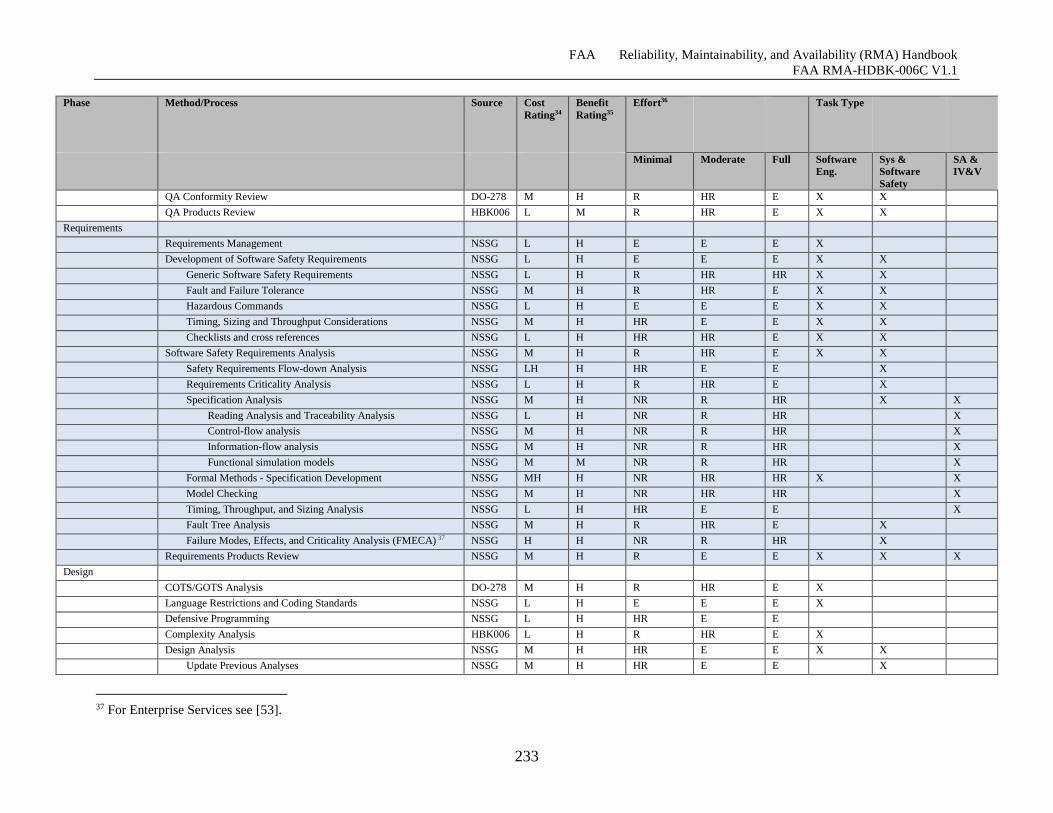
FAA Reliability, Maintainability, and Availability (RMA) Handbook
FAA RMA-HDBK-006C V1.1
233
Phase Method/Process Source Cost
Rating34
Benefit
Rating35
Effort36 Task Type
Minimal Moderate Full Software
Eng.
Sys &
Software
Safety
SA &
IV&V
QA Conformity Review DO-278 M H R HR E X X
QA Products Review HBK006 L M R HR E X X
Requirements
Requirements Management NSSG L H E E E X
Development of Software Safety Requirements NSSG L H E E E X X
Generic Software Safety Requirements NSSG L H R HR HR X X
Fault and Failure Tolerance NSSG M H R HR E X X
Hazardous Commands NSSG L H E E E X X
Timing, Sizing and Throughput Considerations NSSG M H HR E E X X
Checklists and cross references NSSG L H HR HR E X X
Software Safety Requirements Analysis NSSG M H R HR E X X
Safety Requirements Flow-down Analysis NSSG LH H HR E E X
Requirements Criticality Analysis NSSG L H R HR E X
Specification Analysis NSSG M H NR R HR X X
Reading Analysis and Traceability Analysis NSSG L H NR R HR X
Control-flow analysis NSSG M H NR R HR X
Information-flow analysis NSSG M H NR R HR X
Functional simulation models NSSG M M NR R HR X
Formal Methods - Specification Development NSSG MH H NR HR HR X X
Model Checking NSSG M H NR HR HR X
Timing, Throughput, and Sizing Analysis NSSG L H HR E E X
Fault Tree Analysis NSSG M H R HR E X
Failure Modes, Effects, and Criticality Analysis (FMECA) 37 NSSG H H NR R HR X
Requirements Products Review NSSG M H R E E X X X
Design
COTS/GOTS Analysis DO-278 M H R HR E X
Language Restrictions and Coding Standards NSSG L H E E E X
Defensive Programming NSSG L H HR E E
Complexity Analysis HBK006 L H R HR E X
Design Analysis NSSG M H HR E E X X
Update Previous Analyses NSSG M H HR E E X
37 For Enterprise Services see [53].
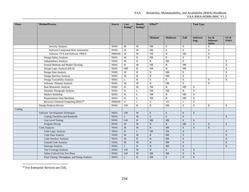
FAA Reliability, Maintainability, and Availability (RMA) Handbook
FAA RMA-HDBK-006C V1.1
234
Phase Method/Process Source Cost
Rating34
Benefit
Rating35
Effort36 Task Type
Minimal Moderate Full Software
Eng.
Sys &
Software
Safety
SA &
IV&V
Severity Analysis NSSG M M HR E E X
Software Component Risk Assessment NSSG M M HR E E X
Software FTA and Software FMEA HBK006 M M NR R HR X
Design Safety Analysis NSSG M H HR E E X
Independence Analysis NSSG M H R HR E X
Formal Methods and Model Checking NSSG H M NR R HR X
Design Logic Analysis (DLA) NSSG MH H NR R HR X
Design Data Analysis NSSG M H R HR E X
Design Interface Analysis NSSG M H R HR E X
Design Traceability Analysis NSSG L H E E E X X
Software Element Analysis NSSG M M R HR E X
Rate Monotonic Analysis NSSG H M NR R HR X
Dynamic Flowgraph Analysis NSSG H L NR NR R X
Markov Modeling NSSG H L NR R HR X
Requirements State Machines NSSG H L NR R HR X
Recovery Oriented Computing (ROC)38 HBK006 H L R HR E X
Design Products Review NSSG LM H R HR E X X X
Coding
Software Development Techniques NSSG LM M E E E X
Coding Checklists and Standards NSSG L M E E E X
Unit Level Testing NSSG LM H HR HR E X
Program Slicing NSSG M M R R HR X X X
Code Analyses NSSG M M R HR E X X
Code Logic Analysis NSSG H L NR NR R X
Code Data Analysis NSSG M M R HR E X
Code Interface Analysis NSSG M H R HR E X
Unused Code Analysis NSSG M M R HR E X
Interrupt Analysis NSSG L H R HR E X
Test Coverage Analysis NSSG LM M R E E X
Safety-Critical Unit Test Plans NSSG LM M HR HR E X
Final Timing, Throughput, and Sizing Analysis NSSG L H HR E E X
38 For Enterprise Services see [54].
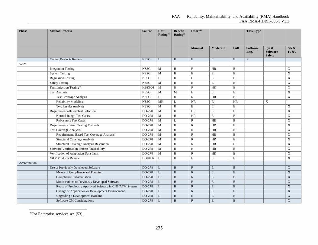
FAA Reliability, Maintainability, and Availability (RMA) Handbook
FAA RMA-HDBK-006C V1.1
235
Phase Method/Process Source Cost
Rating34
Benefit
Rating35
Effort36 Task Type
Minimal Moderate Full Software
Eng.
Sys &
Software
Safety
SA &
IV&V
Coding Products Review NSSG L H E E E X
V&V
Integration Testing NSSG M H R HR E X
System Testing NSSG M H E E E X
Regression Testing NSSG L H E E E X
Safety Testing NSSG M H E E E X
Fault Injection Testing39 HBK006 M H R HR E X
Test Analysis NSSG M M E E E X
Test Coverage Analysis NSSG L H R HR E X
Reliability Modeling NSSG MH L NR R HR X
Test Results Analysis NSSG M H E E E X
Requirements-Based Test Selection DO-278 M H HR E E X
Normal Range Test Cases DO-278 M H HR E E X
Robustness Test Cases DO-278 M L R HR E X
Requirements Based Testing Methods DO-278 M H R HR E X
Test Coverage Analysis DO-278 M H R HR E X
Requirements-Based Test Coverage Analysis DO-278 M H R HR E X
Structural Coverage Analysis DO-278 M H R HR E X
Structural Coverage Analysis Resolution DO-278 M H R HR E X
Software Verification Process Traceability DO-278 M H R HR E X
Verification of Adaptation Data Items DO-278 M H R HR E X
V&V Products Review HBK006 L H E E E X
Accreditation
Use of Previously Developed Software DO-278 L H R E E X
Means of Compliance and Planning DO-278 L H R E E X
Compliance Substantiation DO-278 L H R E E X
Modifications to Previously Developed Software DO-278 L H R E E X
Reuse of Previously Approved Software in CNS/ATM System DO-278 L H R E E X
Change of Application or Development Environment DO-278 L H R E E X
Upgrading a Development Baseline DO-278 L H R E E X
Software CM Considerations DO-278 L H R E E X
39For Enterprise services see [53].
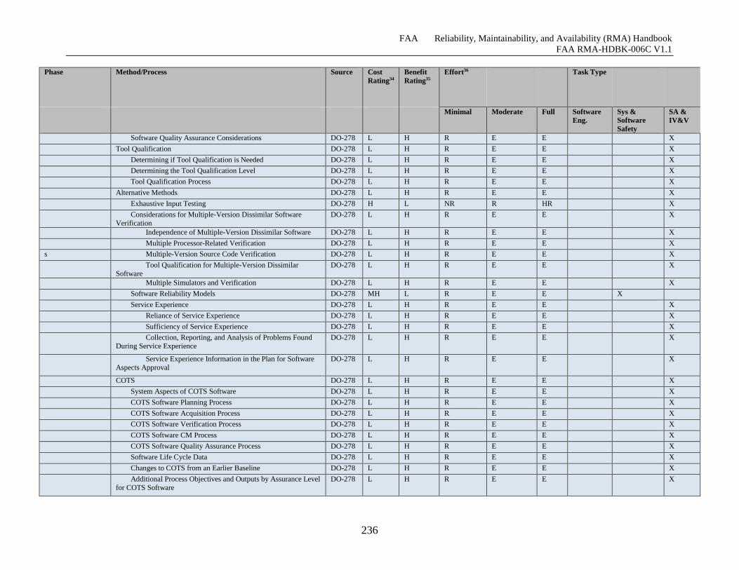
FAA Reliability, Maintainability, and Availability (RMA) Handbook
FAA RMA-HDBK-006C V1.1
236
Phase Method/Process Source Cost
Rating34
Benefit
Rating35
Effort36 Task Type
Minimal Moderate Full Software
Eng.
Sys &
Software
Safety
SA &
IV&V
Software Quality Assurance Considerations DO-278 L H R E E X
Tool Qualification DO-278 L H R E E X
Determining if Tool Qualification is Needed DO-278 L H R E E X
Determining the Tool Qualification Level DO-278 L H R E E X
Tool Qualification Process DO-278 L H R E E X
Alternative Methods DO-278 L H R E E X
Exhaustive Input Testing DO-278 H L NR R HR X
Considerations for Multiple-Version Dissimilar Software
Verification
DO-278 L H R E E X
Independence of Multiple-Version Dissimilar Software DO-278 L H R E E X
Multiple Processor-Related Verification DO-278 L H R E E X
s Multiple-Version Source Code Verification DO-278 L H R E E X
Tool Qualification for Multiple-Version Dissimilar
Software
DO-278 L H R E E X
Multiple Simulators and Verification DO-278 L H R E E X
Software Reliability Models DO-278 MH L R E E X
Service Experience DO-278 L H R E E X
Reliance of Service Experience DO-278 L H R E E X
Sufficiency of Service Experience DO-278 L H R E E X
Collection, Reporting, and Analysis of Problems Found
During Service Experience
DO-278 L H R E E X
Service Experience Information in the Plan for Software
Aspects Approval
DO-278 L H R E E X
COTS DO-278 L H R E E X
System Aspects of COTS Software DO-278 L H R E E X
COTS Software Planning Process DO-278 L H R E E X
COTS Software Acquisition Process DO-278 L H R E E X
COTS Software Verification Process DO-278 L H R E E X
COTS Software CM Process DO-278 L H R E E X
COTS Software Quality Assurance Process DO-278 L H R E E X
Software Life Cycle Data DO-278 L H R E E X
Changes to COTS from an Earlier Baseline DO-278 L H R E E X
Additional Process Objectives and Outputs by Assurance Level
for COTS Software
DO-278 L H R E E X
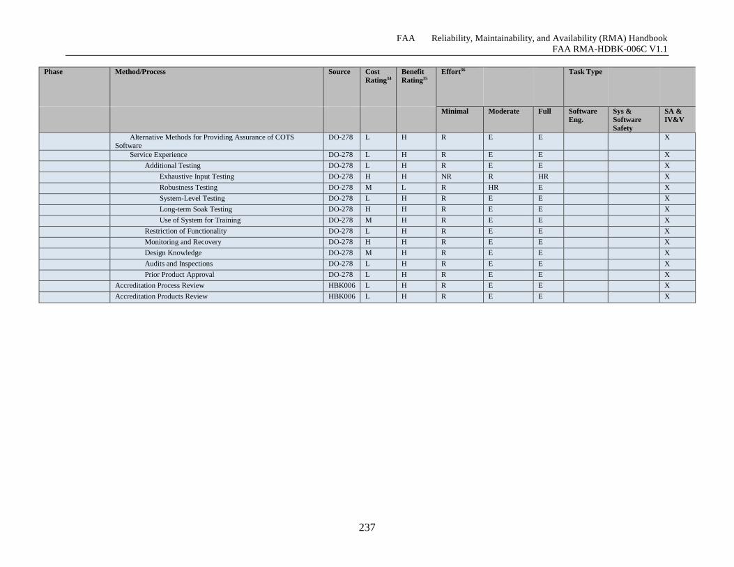
FAA Reliability, Maintainability, and Availability (RMA) Handbook
FAA RMA-HDBK-006C V1.1
237
Phase Method/Process Source Cost
Rating34
Benefit
Rating35
Effort36 Task Type
Minimal Moderate Full Software
Eng.
Sys &
Software
Safety
SA &
IV&V
Alternative Methods for Providing Assurance of COTS Software
DO-278 L H R E E X
Service Experience DO-278 L H R E E X
Additional Testing DO-278 L H R E E X
Exhaustive Input Testing DO-278 H H NR R HR X
Robustness Testing DO-278 M L R HR E X
System-Level Testing DO-278 L H R E E X
Long-term Soak Testing DO-278 H H R E E X
Use of System for Training DO-278 M H R E E X
Restriction of Functionality DO-278 L H R E E X
Monitoring and Recovery DO-278 H H R E E X
Design Knowledge DO-278 M H R E E X
Audits and Inspections DO-278 L H R E E X
Prior Product Approval DO-278 L H R E E X
Accreditation Process Review HBK006 L H R E E X
Accreditation Products Review HBK006 L H R E E X
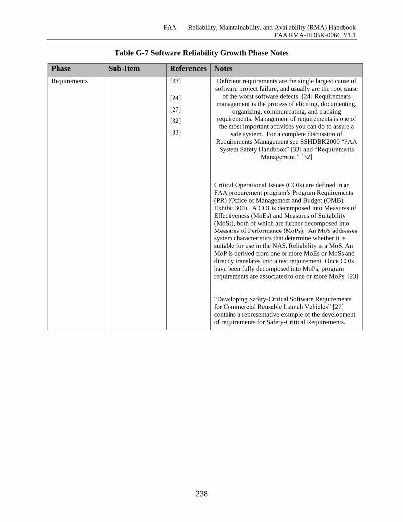
FAA Reliability, Maintainability, and Availability (RMA) Handbook
FAA RMA-HDBK-006C V1.1
238
Table G-7 Software Reliability Growth Phase Notes
Phase Sub-Item References Notes
Requirements [23]
[24]
[27]
[32]
[33]
Deficient requirements are the single largest cause of
software project failure, and usually are the root cause
of the worst software defects. [24] Requirements
management is the process of eliciting, documenting,
organizing, communicating, and tracking
requirements. Management of requirements is one of
the most important activities you can do to assure a
safe system. For a complete discussion of
Requirements Management see SSHDBK2000 “FAA
System Safety Handbook” [33] and “Requirements
Management.” [32]
Critical Operational Issues (COIs) are defined in an
FAA procurement program’s Program Requirements
(PR) (Office of Management and Budget (OMB)
Exhibit 300). A COI is decomposed into Measures of
Effectiveness (MoEs) and Measures of Suitability
(MoSs), both of which are further decomposed into
Measures of Performance (MoPs). An MoS addresses
system characteristics that determine whether it is
suitable for use in the NAS. Reliability is a MoS. An
MoP is derived from one or more MoEs or MoSs and
directly translates into a test requirement. Once COIs
have been fully decomposed into MoPs, program
requirements are associated to one or more MoPs. [23]
“Developing Safety-Critical Software Requirements
for Commercial Reusable Launch Vehicles” [27]
contains a representative example of the development
of requirements for Safety-Critical Requirements.
FAA Reliability, Maintainability, and Availability (RMA) Handbook
FAA RMA-HDBK-006C V1.1
239
Phase Sub-Item References Notes
Configuration
Management
Change
Control/Change
Review
[18] Change Management is applicable to all phases of
Engineering Life-cycle. Change Management it is key
to Software Reliability Growth since it provides a
basis for the recording of metrics (Section Metrics)
and fault classification (Section Software Fault
Taxonomies).
Requirements Failure Mode,
Effects, and
Severity Analysis
(FMECA)
Studies have shown that the biggest reason for software
failures is not having stable software requirements
during the requirements process. Software designers
should address software in system reliability design and
analysis activities. A system’s software should be
reproduced in the reliability block diagram, else it is
given the assumption that the software will never fail.
Further, if a system includes software, then the FMECA
should recognize the software as a potential failure
point. Neglecting the software makes that assumption
that it will be error-free. [13]
FMECA is a bottoms-up analysis that starts with
individual components up to the overall failure. The
technique can be improved to indicate increased
understanding of the system as more details become
available. [24]
FMECA is an excellent hazard analysis and risk
assessment tool, but it has its own limitations. This
alternative does not take into consideration any
software and human interactions as well as combined
failures. Also, it usually provides an optimistic
estimate of reliability. As such, FMECA should be
supplemented with other analytical tools to develop
accurate reliability estimates [15]. Authoritative
sources for software FMEA/FMECA include IEC
60812:2006(E) [35].
Implementation [19]
[20]
[25]
Unit Level Testing [26]
V&V [13]
[17]
[26]
[31]
FAA Reliability, Maintainability, and Availability (RMA) Handbook
FAA RMA-HDBK-006C V1.1
240
G.4 Overarching Methodologies & Tools
G.4.1 Metrics
A reliability specification necessitates an explanation of what represents mission success or
failure. Several popular reliability metrics include: failure rate, mean time between failure
(MTBF), and mean time between repairs (MTBR).
Software reliability metrics are similar to hardware metrics for a repairable system. The data
provided is commonly a series of failure times or other events. The data is used during software
development to measure time between events, analyze the improvement resulting from removing
errors and making decisions about when to release or update a software product version. Metrics
are also used to assess software or system stability. [13]
G.4.2 Software Fault Taxonomies
Orthogonal Defect Classification (ODC) essentially illustrates a way to categorize a defect into
different classes that indicate the part of the process that needs investigation. In the software
development process, there are many variations by different organizations although activities are
broadly divided into design, code, and test. [14]
An understanding of the relationship between reliability metrics and other terms is necessary for
the application of these factors. System failures may be caused by the hardware, the user, or
faulty maintenance.
The basic Software Reliability incident classification includes:
Mission failures – loss of any essential functions, including system hardware failures,
operator errors, and publication errors. Related to mission reliability.
System failures – software malfunction that may affect essential functions. Related to
maintenance reliability.
Unscheduled spares demands – Related to supply reliability.
System/ mission failures requiring spares – Related to mission, maintenance and supply
reliabilities. [17]
G.4.3 Tools
There is a plethora of tools that can be used in at the various Engineering Life-cycle phases for
Software Reliability. Authoritative sources on this subject include DOT/FAA/AR-06/35
“Software Development Tools for Safety-Critical, Real-Time Systems Handbook” [25]and
DOT/FAA/AR-06/36 “Assessment of Software Development Tools for Safety-Critical, Real-
Time Systems.[21] Specific GOTS tools include the U.S. Army Materiel Systems Analysis
Activity (AMSAA) Reliability Growth technology. [10] [16]
.
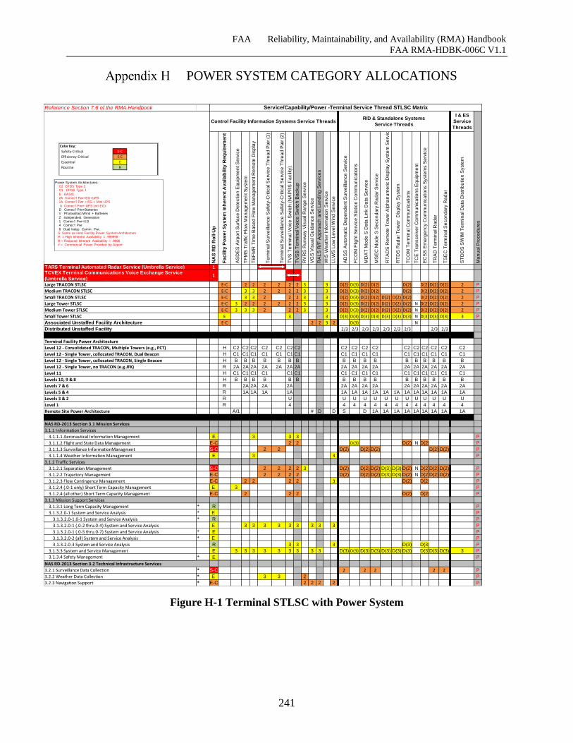
FAA Reliability, Maintainability, and Availability (RMA) Handbook
FAA RMA-HDBK-006C V1.1
241
POWER SYSTEM CATEGORY ALLOCATIONS
Figure H-1 Terminal STLSC with Power System
Reference Section 7.6 of the RMA Handbook
I & ES
Service
Threads
NA
S R
D R
oll-U
p
Fa
cilit
y P
ow
er
Sy
ste
m In
he
ren
t A
va
ila
bilit
y R
eq
uir
em
en
t
AS
DE
S A
irp
ort
Su
rfa
ce
De
tectio
n E
qu
ipm
en
t S
erv
ice
TF
MS
Tra
ffic
Flo
w M
an
ag
em
en
t S
yste
m
TB
FM
R T
ime
Ba
se
d F
low
Ma
na
ge
me
nt R
em
ote
Dis
pla
y
Te
rmin
al S
urv
eill
an
ce
Sa
fety
-Critica
l S
erv
ice
Th
rea
d P
air (
1)
Te
rmin
al S
urv
eill
an
ce
Sa
fety
-Critica
l S
erv
ice
Th
rea
d P
air (
2)
TV
S T
erm
ina
l V
oic
e S
witch
(N
AP
RS
Fa
cili
ty)
TV
SB
Te
rmin
al V
oic
e S
witch
Ba
cku
p
RV
RS
Ru
nw
ay V
isu
al R
an
ge
Se
rvic
e
VG
S V
isu
al G
uid
an
ce
Se
rvic
e
RA
LS
R/F
Ap
pro
ach
an
d L
an
din
g S
erv
ice
s
WIS
We
ath
er
Info
rma
tio
n S
erv
ice
LL
WS
Lo
w L
eve
l W
ind
Se
rvic
e
AD
SS
Au
tom
atic D
ep
en
de
nt S
urv
eill
an
ce
Se
rvic
e
FC
OM
Flig
ht S
erv
ice
Sta
tio
n C
om
mu
nic
atio
ns
MD
AT
Mo
de
S D
ata
Lin
k D
ata
Se
rvic
e
MS
EC
Mo
de
S S
eco
nd
ary
Ra
da
r S
erv
ice
RT
AD
S R
em
ote
To
we
r A
lph
an
um
eric D
isp
lay S
yste
m S
erv
ice
RT
DS
Ra
da
r T
ow
er
Dis
pla
y S
yste
m
TC
OM
Te
rmin
al C
om
mu
nic
atio
ns
TC
E T
ran
sce
ive
r C
om
mu
nic
atio
ns E
qu
ipm
en
t
EC
SS
Em
erg
en
cy C
om
mu
nic
atio
ns S
yste
ms S
erv
ice
TR
AD
Te
rmin
al R
ad
ar
TS
EC
Te
rmin
al S
eco
nd
ary
Ra
da
r
ST
DD
S S
WIM
Te
rmin
al D
ata
Dis
trib
utio
n S
yste
m
Ma
nu
al P
roce
du
res
1
1
E-C 2 2 2 2 2 2 3 3 D(2) D(3) D(2) D(2) D(2) D(2) D(2) D(2) 2 P
E-C 3 3 2 2 2 2 3 3 D(2) D(3) D(2) D(2) D(2) D(2) D(2) D(2) 2 P
E-C 3 3 2 2 2 3 3 D(2) D(3) D(2) D(2) D(2) D(2) D(2) D(2) D(2) D(2) 2 P
E-C 3 2 2 2 2 2 2 3 3 D(2) D(3) D(2) D(2) D(2) D(2) D(2) N D(2) D(2) D(2) 2 P
E-C 3 3 3 2 2 2 3 3 D(2) D(3) D(2) D(2) D(2) D(2) D(2) N D(2) D(2) D(2) 2 P
E 3 3 D(3) D(3) D(3) D(3) D(3) D(3) D(3) N D(3) D(3) D(3) 3 P
E-C 2 2 3 2 D(3) N
2/3 2/3 2/3 2/3 2/3 2/3 2/3 2/3 2/3
Terminal Facility Power Architecture
Level 12 - Consolidated TRACON, Multiple Towers (e.g., PCT) H C2 C2 C2 C2 C2 C2 C2 C2 C2 C2 C2 C2 C2 C2 C2 C2C2 C2
Level 12 - Single Tower, collocated TRACON, Dual Beacon H C1 C1 C1 C1 C1 C1 C1 C1 C1 C1 C1 C1 C1 C1 C1 C1C1 C1
Level 12 - Single Tower, collocated TRACON, Single Beacon H B B B B B B B B B B B B B B B B B B
Level 12 - Single Tower, no TRACON (e.g.JFK) R 2A 2A 2A 2A 2A 2A 2A 2A 2A 2A 2A 2A 2A 2A 2A 2A2A 2A
Level 11 H C1 C1 C1 C1 C1 C1 C1 C1 C1 C1 C1 C1 C1 C1 C1C1 C1
Levels 10, 9 & 8 H B B B B B B B B B B B B B B B B B
Levels 7 & 6 R 2A 2A 2A 2A 2A 2A 2A 2A 2A 2A 2A 2A 2A2A 2A
Levels 5 & 4 R 1A 1A 1A 1A 1A 1A 1A 1A 1A 1A 1A 1A 1A 1A 1A1A 1A
Levels 3 & 2 R U U U U U U U U U U U U U U
Level 1 R 4 4 4 4 4 4 4 4 4 4 4 4 4
Remote Site Power Architecture A/1 # D D S D 1A 1A 1A 1A 1A 1A 1A 1A1A 1A
3.1.1 Information Services
3.1.1.1 Aeronautical Information Management E 3 3 3 P
3.1.1.2 Flight and State Data Management E-C 2 2 D(3) D(2) N D(2) P
3.1.1.3 Surveillance InformationManagment S-C 2 2 D(2) D(2) D(2) D(2) D(2) P
3.1.1.4 Weather Information Management E 3 3 P
3.1.2 Traffic Services
3.1.2.1 Separation Management S-C 2 2 2 2 3 D(2) D(2) D(2) D(3) D(3) D(2) N D(2)D(2) D(2) P
3.1.2.2 Trajectory Management E-C 2 2 2 2 D(2) D(2) D(2) D(3) D(3) D(2) N D(2)D(2) D(2) P
3.1.2.3 Flow Contingency Management E-C 2 2 2 2 3 D(2) D(2) P
3.1.2.4 (.0-1 only) Short Term Capacity Management E 3 P
3.1.2.4 (all other) Short Term Capacity Management E-C 2 2 2 D(2) D(2) P
3.1.3 Mission Support Services
3.1.3.1 Long Term Capacity Management * R P
3.1.3.2.0-1 System and Service Analysis * E P
3.1.3.2.0-1.0-1 System and Service Analysis * R P
3.1.3.2.0-1 (.0-2 thru.0-4) System and Service Analysis E 3 3 3 3 3 3 3 3 3 P
3.1.3.2.0-1 (.0-5 thru.0-7) System and Service Analysis * E P
3.1.3.2.0-2 (all) System and Service Analysis * E P
3.1.3.2.0-3 System and Service Analysis R 3 3 3 D(3) D(3) P
3.1.3.3 System and Service Management E 3 3 3 3 3 3 3 3 3 D(3) D(3) D(3) D(3) D(3) D(3) D(3) D(3)D(3) D(3) 3 P
3.1.3.4 Safety Management * E P
3.2.1 Surveillance Data Collection * S-C 2 2 2 2 2 P
3.2.2 Weather Data Collection * E 3 3 2 P
3.2.3 Navigation Support * E-C 2 2 2 2 P
Small Tower STLSC
Associated Unstaffed Facility Architecture
Distributed Unstaffed Facility
NAS RD-2013 Section 3.1 Mission Services
Service/Capability/Power -Terminal Service Thread STLSC Matrix
Control Facility Information Systems Service ThreadsR/D & Standalone Systems
Service Threads
TARS Terminal Automated Radar Service (Umbrella Service)TCVEX Terminal Communications Voice Exchange Service
(Umbrella Service)
Large TRACON STLSC
Medium TRACON STLSC
Small TRACON STLSC
NAS RD-2013 Section 3.2 Technical Infrastructure Services
Large Tower STLSC
Medium Tower STLSC
Color Key:
Safety-Critical S-C
Efficiency-Critical E-C
Essential E
Routine R
Power System Architectures::C2 CPDS Type 2 C1 CPDS Type 1
B BASIC 2A Comec'l Pwr+EG+UPS1A Comec'l Pwr + EG + Mini UPS
U Comec'l Pwr+ UPS (no EG)D Comec'l Pwr+BatteriesV Photovoltaic/Wind + Batteries
Z Independent Generation1 Comec'l Pwr+EG4 Comec'l Pwr
8 Dual Indep. Comm. Pwr. S Same as Host Facility Power System ArchitectureH = High Inherent Availability = .999998
R = Reduced Inherent Availability = .9998# = Commercial Power Provided by Airport
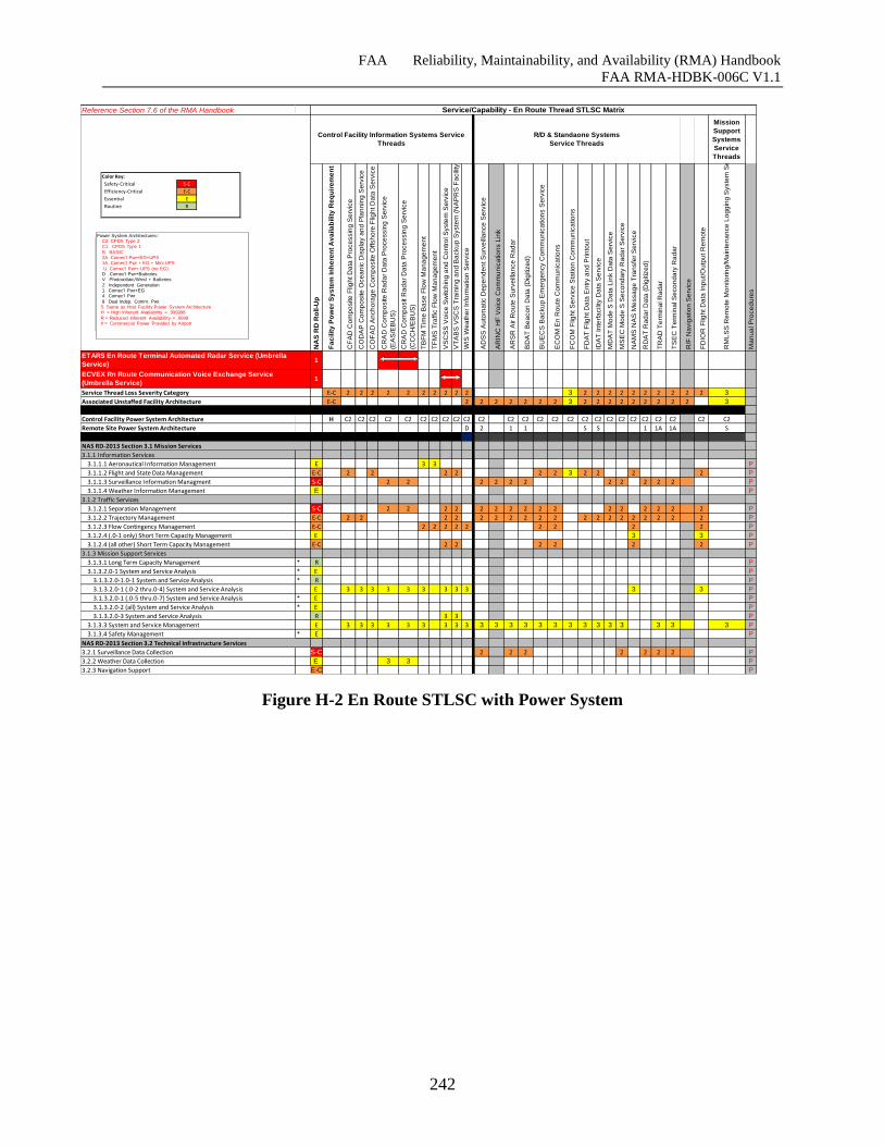
FAA Reliability, Maintainability, and Availability (RMA) Handbook
FAA RMA-HDBK-006C V1.1
242
Figure H-2 En Route STLSC with Power System
Reference Section 7.6 of the RMA Handbook
Mission
Support
Systems
Service
Threads
NA
S R
D R
oll-U
p
Fa
cilit
y P
ow
er
Sy
ste
m In
he
ren
t A
va
ila
bilit
y R
eq
uir
em
en
t
CF
AD
Co
mp
osite
Flig
ht D
ata
Pro
ce
ssin
g S
erv
ice
CO
DA
P C
om
po
site
Oce
an
ic D
isp
lay a
nd
Pla
nn
ing
Se
rvic
e
CO
FA
D A
nch
ora
ge
Co
mp
osite
Offsh
ore
Flig
ht D
ata
Se
rvic
e
CR
AD
Co
mp
osite
Ra
da
r D
ata
Pro
ce
ssin
g S
erv
ice
(EA
S/E
BU
S)
CR
AD
Co
mp
osit R
ad
ar
Da
ta P
roce
ssin
g S
erv
ice
(CC
CH
/EB
US
)
TB
FM
Tim
e B
ase
Flo
w M
an
ag
em
en
t
TF
MS
Tra
ffic
Flo
w M
an
ag
em
en
t
VS
CS
S V
oic
e S
witch
ing
an
d C
on
tro
l S
yste
m S
erv
ice
VT
AB
S V
SC
S T
rain
ing
an
d B
acku
p S
yste
m (
NA
PR
S F
acili
ty)
WIS
We
ath
er
Info
rma
tio
n S
erv
ice
AD
SS
Au
tom
atic D
ep
en
de
nt S
urv
eill
an
ce
Se
rvic
e
AR
INC
HF
Vo
ice
Co
mm
un
ica
tio
ns L
ink
AR
SR
Air R
ou
te S
urv
eill
an
ce
Ra
da
r
BD
AT
Be
aco
n D
ata
(D
igitiz
ed
)
BU
EC
S B
acku
p E
me
rge
ncy C
om
mu
nic
atio
ns S
erv
ice
EC
OM
En
Ro
ute
Co
mm
un
ica
tio
ns
FC
OM
Flig
ht S
erv
ice
Sta
tio
n C
om
mu
nic
atio
ns
FD
AT
Flig
ht D
ata
En
try a
nd
Prin
tou
t
IDA
T In
terf
acili
ty D
ata
Se
rvic
e
MD
AT
Mo
de
S D
ata
Lin
k D
ata
Se
rvic
e
MS
EC
Mo
de
S S
eco
nd
ary
Ra
da
r S
erv
ice
NA
MS
NA
S M
essa
ge
Tra
nsfe
r S
erv
ice
RD
AT
Ra
da
r D
ata
(D
igitiz
ed
)
TR
AD
Te
rmin
al R
ad
ar
TS
EC
Te
rmin
al S
eco
nd
ary
Ra
da
r
R/F
Na
vig
atio
n S
erv
ice
FD
IOR
Flig
ht D
ata
In
pu
t/O
utp
ut R
em
ote
RM
LS
S R
em
ote
Mo
nito
rin
g/M
ain
ten
an
ce
Lo
gg
ing
Syste
m S
erv
ice
Ma
nu
al P
roce
du
res
1
1
E-C 2 2 2 2 2 2 2 2 2 2 3 2 2 2 2 2 2 2 2 2 2 3
E-C 2 2 2 2 2 2 2 3 2 2 2 2 2 2 2 2 2 3
Control Facility Power System Architecture H C2 C2 C2 C2 C2 C2 C2 C2 C2 C2 C2 C2 C2 C2 C2 C2 C2 C2 C2 C2 C2 C2 C2 C2 C2 C2
Remote Site Power System Architecture D 2 1 1 S S 1 1A 1A S
3.1.1 Information Services
3.1.1.1 Aeronautical Information Management E 3 3 P
3.1.1.2 Flight and State Data Management E-C 2 2 2 2 2 2 3 2 2 2 2 P
3.1.1.3 Surveillance Information Managment S-C 2 2 2 2 2 2 2 2 2 2 2 P
3.1.1.4 Weather Information Management E P
3.1.2 Traffic Services
3.1.2.1 Separation Management S-C 2 2 2 2 2 2 2 2 2 2 2 2 2 2 2 2 P
3.1.2.2 Trajectory Management E-C 2 2 2 2 2 2 2 2 2 2 2 2 2 2 2 2 2 2 2 P
3.1.2.3 Flow Contingency Management E-C 2 2 2 2 2 2 2 2 2 P
3.1.2.4 (.0-1 only) Short Term Capacity Management E 3 3 P
3.1.2.4 (all other) Short Term Capacity Management E-C 2 2 2 2 2 2 P
3.1.3 Mission Support Services
3.1.3.1 Long Term Capacity Management * R P
3.1.3.2.0-1 System and Service Analysis * E P
3.1.3.2.0-1.0-1 System and Service Analysis * R P
3.1.3.2.0-1 (.0-2 thru.0-4) System and Service Analysis E 3 3 3 3 3 3 3 3 3 3 3 P
3.1.3.2.0-1 (.0-5 thru.0-7) System and Service Analysis * E P
3.1.3.2.0-2 (all) System and Service Analysis * E P
3.1.3.2.0-3 System and Service Analysis R 3 3 P
3.1.3.3 System and Service Management E 3 3 3 3 3 3 3 3 3 3 3 3 3 3 3 3 3 3 3 3 3 3 3 P
3.1.3.4 Safety Management * E P
3.2.1 Surveillance Data Collection S-C 2 2 2 2 2 2 2 P
3.2.2 Weather Data Collection E 3 3 P
3.2.3 Navigation Support E-C P
NAS RD-2013 Section 3.2 Technical Infrastructure Services
Service/Capability - En Route Thread STLSC Matrix
Control Facility Information Systems Service
Threads
R/D & Standaone Systems
Service Threads
ETARS En Route Terminal Automated Radar Service (Umbrella
Service)
ECVEX Rn Route Communication Voice Exchange Service
(Umbrella Service)
Service Thread Loss Severity Category
Associated Unstaffed Facility Architecture
NAS RD-2013 Section 3.1 Mission Services
Color Key:
Safety-Critical S-C
Efficiency-Critical E-C
Essential E
Routine R
Power System Architectures::C2 CPDS Type 2 C1 CPDS Type 1
B BASIC 2A Comec'l Pwr+EG+UPS1A Comec'l Pwr + EG + Mini UPS
U Comec'l Pwr+ UPS (no EG)D Comec'l Pwr+BatteriesV Photovoltaic/Wind + Batteries
Z Independent Generation1 Comec'l Pwr+EG4 Comec'l Pwr
8 Dual Indep. Comm. Pwr. S Same as Host Facility Power System ArchitectureH = High Inherent Availability = .999998
R = Reduced Inherent Availability = .9998# = Commercial Power Provided by Airport
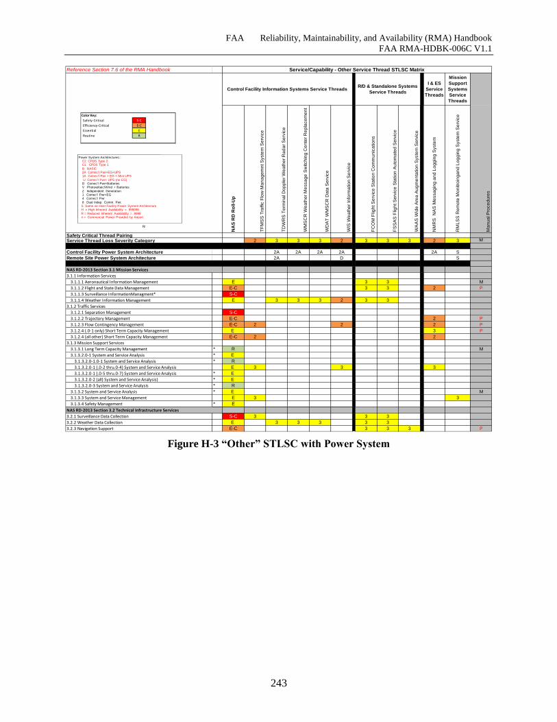
FAA Reliability, Maintainability, and Availability (RMA) Handbook
FAA RMA-HDBK-006C V1.1
243
Figure H-3 “Other” STLSC with Power System
Reference Section 7.6 of the RMA Handbook
I & ES
Service
Threads
Mission
Support
Systems
Service
Threads
NA
S R
D R
oll-U
p
TF
MS
S T
raffic
Flo
w M
an
ag
em
nt S
yste
m S
erv
ice
TD
WR
S T
erm
ina
l D
op
ple
r W
ea
the
r R
ad
ar
Se
rvic
e
WM
SC
R W
ea
the
r M
essa
ge
Sw
itch
ing
Ce
nte
r R
ep
lace
me
nt
WD
AT
WM
SC
R D
ata
Se
rvic
e
WIS
We
ath
er
Info
rma
tio
n S
erv
ice
FC
OM
Flig
ht S
erv
ice
Sta
tio
n C
om
mu
nic
atio
ns
FS
SA
S F
ligh
t S
erv
ice
Sta
tio
n A
uto
ma
ted
Se
rvic
e
WA
AS
Wid
e A
rea
Au
gm
en
tatio
n S
yste
m S
erv
ice
NM
RS
N
AS
Me
ssa
gin
g a
nd
Lo
gg
ing
Syste
m
RM
LS
S R
em
ote
Mo
nitro
ing
an
d L
og
gin
g S
yste
m S
erv
ice
Ma
nu
al P
roce
du
res
2 3 3 3 2 3 3 3 2 3 M
Control Facility Power System Architecture 2A 2A 2A 2A 2A S
Remote Site Power System Architecture 2A D S
3.1.1 Information Services
3.1.1.1 Aeronautical Information Management E 3 3 M
3.1.1.2 Flight and State Data Management E-C 3 3 2 P
3.1.1.3 Surveillance InformationManagment* S-C
3.1.1.4 Weather Information Management E 3 3 3 2 3 3
3.1.2 Traffic Services
3.1.2.1 Separation Management S-C
3.1.2.2 Trajectory Management E-C 2 P
3.1.2.3 Flow Contingency Management E-C 2 2 2 P
3.1.2.4 (.0-1 only) Short Term Capacity Management E 3 P
3.1.2.4 (all other) Short Term Capacity Management E-C 2 2
3.1.3 Mission Support Services
3.1.3.1 Long Term Capacity Management * R M
3.1.3.2.0-1 System and Service Analysis * E
3.1.3.2.0-1.0-1 System and Service Analysis * R
3.1.3.2.0-1 (.0-2 thru.0-4) System and Service Analysis E 3 3 3
3.1.3.2.0-1 (.0-5 thru.0-7) System and Service Analysis * E
3.1.3.2.0-2 (all) System and Service Analysis) * E
3.1.3.2.0-3 System and Service Analysis * R
3.1.3.2 System and Service Analysis * E M
3.1.3.3 System and Service Management E 3 3
3.1.3.4 Safety Management * E
3.2.1 Surveillance Data Collection S-C 3 3 3
3.2.2 Weather Data Collection E 3 3 3 3 3
3.2.3 Navigation Support E-C 3 3 3 P
Service/Capability - Other Service Thread STLSC Matrix
R/
Control Facility Information Systems Service ThreadsR/D & Standalone Systems
Service Threads
Safety Critical Thread PairingService Thread Loss Severity Category
NAS RD-2013 Section 3.1 Mission Services
NAS RD-2013 Section 3.2 Technical Infrastructure Services
Color Key:
Safety-Critical S-C
Efficiency-Critical E-C
Essential E
Routine R
Power System Architectures::C2 CPDS Type 2 C1 CPDS Type 1
B BASIC 2A Comec'l Pwr+EG+UPS1A Comec'l Pwr + EG + Mini UPS
U Comec'l Pwr+ UPS (no EG)D Comec'l Pwr+BatteriesV Photovoltaic/Wind + Batteries
Z Independent Generation1 Comec'l Pwr+EG4 Comec'l Pwr
8 Dual Indep. Comm. Pwr. S Same as Host Facility Power System ArchitectureH = High Inherent Availability = .999998
R = Reduced Inherent Availability = .9998# = Commercial Power Provided by Airport
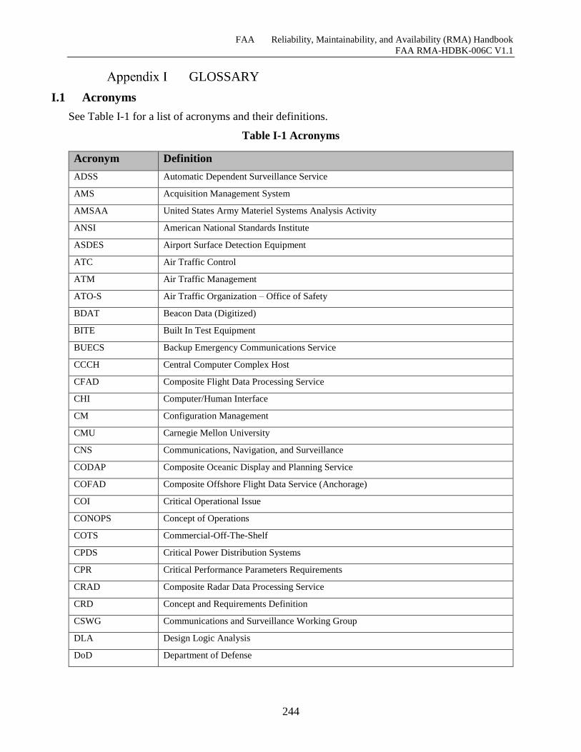
FAA Reliability, Maintainability, and Availability (RMA) Handbook
FAA RMA-HDBK-006C V1.1
244
GLOSSARY
I.1 Acronyms
See Table I-1 for a list of acronyms and their definitions.
Table I-1 Acronyms
Acronym Definition
ADSS Automatic Dependent Surveillance Service
AMS Acquisition Management System
AMSAA United States Army Materiel Systems Analysis Activity
ANSI American National Standards Institute
ASDES Airport Surface Detection Equipment
ATC Air Traffic Control
ATM Air Traffic Management
ATO-S Air Traffic Organization – Office of Safety
BDAT Beacon Data (Digitized)
BITE Built In Test Equipment
BUECS Backup Emergency Communications Service
CCCH Central Computer Complex Host
CFAD Composite Flight Data Processing Service
CHI Computer/Human Interface
CM Configuration Management
CMU Carnegie Mellon University
CNS Communications, Navigation, and Surveillance
CODAP Composite Oceanic Display and Planning Service
COFAD Composite Offshore Flight Data Service (Anchorage)
COI Critical Operational Issue
CONOPS Concept of Operations
COTS Commercial-Off-The-Shelf
CPDS Critical Power Distribution Systems
CPR Critical Performance Parameters Requirements
CRAD Composite Radar Data Processing Service
CRD Concept and Requirements Definition
CSWG Communications and Surveillance Working Group
DLA Design Logic Analysis
DoD Department of Defense
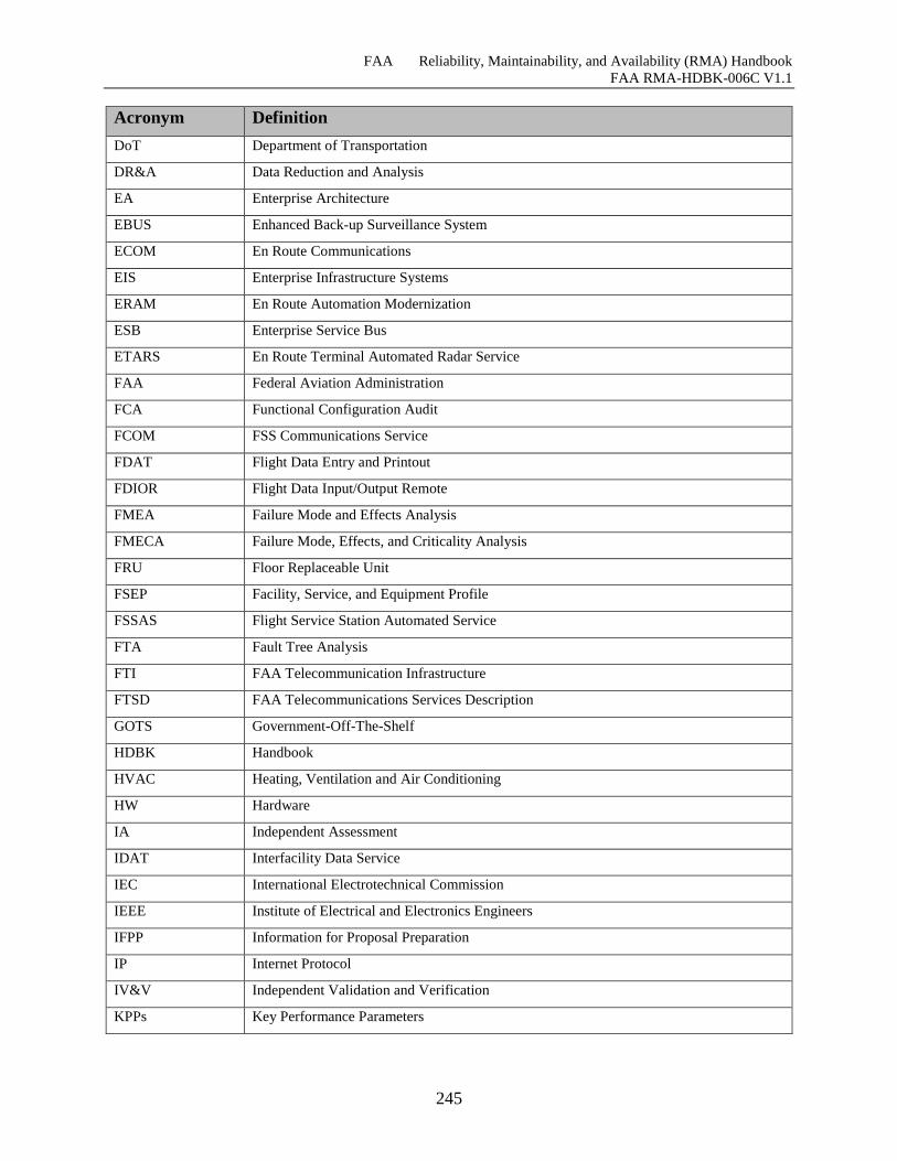
FAA Reliability, Maintainability, and Availability (RMA) Handbook
FAA RMA-HDBK-006C V1.1
245
Acronym Definition
DoT Department of Transportation
DR&A Data Reduction and Analysis
EA Enterprise Architecture
EBUS Enhanced Back-up Surveillance System
ECOM En Route Communications
EIS Enterprise Infrastructure Systems
ERAM En Route Automation Modernization
ESB Enterprise Service Bus
ETARS En Route Terminal Automated Radar Service
FAA Federal Aviation Administration
FCA Functional Configuration Audit
FCOM FSS Communications Service
FDAT Flight Data Entry and Printout
FDIOR Flight Data Input/Output Remote
FMEA Failure Mode and Effects Analysis
FMECA Failure Mode, Effects, and Criticality Analysis
FRU Floor Replaceable Unit
FSEP Facility, Service, and Equipment Profile
FSSAS Flight Service Station Automated Service
FTA Fault Tree Analysis
FTI FAA Telecommunication Infrastructure
FTSD FAA Telecommunications Services Description
GOTS Government-Off-The-Shelf
HDBK Handbook
HVAC Heating, Ventilation and Air Conditioning
HW Hardware
IA Independent Assessment
IDAT Interfacility Data Service
IEC International Electrotechnical Commission
IEEE Institute of Electrical and Electronics Engineers
IFPP Information for Proposal Preparation
IP Internet Protocol
IV&V Independent Validation and Verification
KPPs Key Performance Parameters
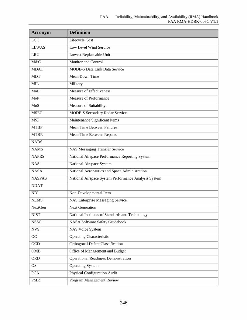
FAA Reliability, Maintainability, and Availability (RMA) Handbook
FAA RMA-HDBK-006C V1.1
246
Acronym Definition
LCC Lifecycle Cost
LLWAS Low Level Wind Service
LRU Lowest Replaceable Unit
M&C Monitor and Control
MDAT MODE-S Data Link Data Service
MDT Mean Down Time
MIL Military
MoE Measure of Effectiveness
MoP Measure of Performance
MoS Measure of Suitability
MSEC MODE-S Secondary Radar Service
MSI Maintenance Significant Items
MTBF Mean Time Between Failures
MTBR Mean Time Between Repairs
NADS
NAMS NAS Messaging Transfer Service
NAPRS National Airspace Performance Reporting System
NAS National Airspace System
NASA National Aeronautics and Space Administration
NASPAS National Airspace System Performance Analysis System
NDAT
NDI Non-Developmental Item
NEMS NAS Enterprise Messaging Service
NextGen Next Generation
NIST National Institutes of Standards and Technology
NSSG NASA Software Safety Guidebook
NVS NAS Voice System
OC Operating Characteristic
OCD Orthogonal Defect Classification
OMB Office of Management and Budget
ORD Operational Readiness Demonstration
OS Operating System
PCA Physical Configuration Audit
PMR Program Management Review
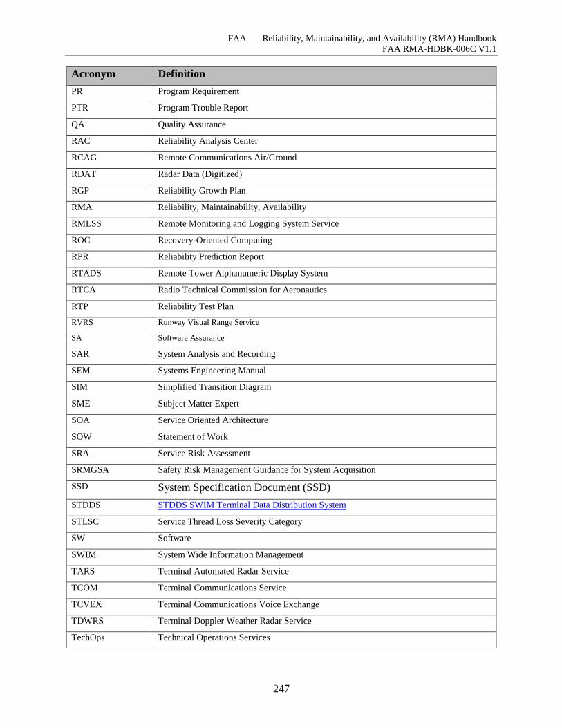
FAA Reliability, Maintainability, and Availability (RMA) Handbook
FAA RMA-HDBK-006C V1.1
247
Acronym Definition
PR Program Requirement
PTR Program Trouble Report
QA Quality Assurance
RAC Reliability Analysis Center
RCAG Remote Communications Air/Ground
RDAT Radar Data (Digitized)
RGP Reliability Growth Plan
RMA Reliability, Maintainability, Availability
RMLSS Remote Monitoring and Logging System Service
ROC Recovery-Oriented Computing
RPR Reliability Prediction Report
RTADS Remote Tower Alphanumeric Display System
RTCA Radio Technical Commission for Aeronautics
RTP Reliability Test Plan
RVRS Runway Visual Range Service
SA Software Assurance
SAR System Analysis and Recording
SEM Systems Engineering Manual
SIM Simplified Transition Diagram
SME Subject Matter Expert
SOA Service Oriented Architecture
SOW Statement of Work
SRA Service Risk Assessment
SRMGSA Safety Risk Management Guidance for System Acquisition
SSD System Specification Document (SSD)
STDDS STDDS SWIM Terminal Data Distribution System
STLSC Service Thread Loss Severity Category
SW Software
SWIM System Wide Information Management
TARS Terminal Automated Radar Service
TCOM Terminal Communications Service
TCVEX Terminal Communications Voice Exchange
TDWRS Terminal Doppler Weather Radar Service
TechOps Technical Operations Services
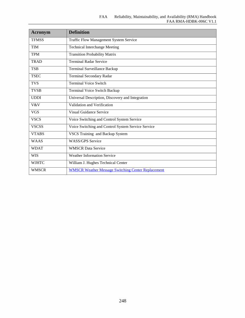
FAA Reliability, Maintainability, and Availability (RMA) Handbook
FAA RMA-HDBK-006C V1.1
248
Acronym Definition
TFMSS Traffic Flow Management System Service
TIM Technical Interchange Meeting
TPM Transition Probability Matrix
TRAD Terminal Radar Service
TSB Terminal Surveillance Backup
TSEC Terminal Secondary Radar
TVS Terminal Voice Switch
TVSB Terminal Voice Switch Backup
UDDI Universal Description, Discovery and Integration
V&V Validation and Verification
VGS Visual Guidance Service
VSCS Voice Switching and Control System Service
VSCSS Voice Switching and Control System Service Service
VTABS VSCS Training and Backup System
WAAS WASS/GPS Service
WDAT WMSCR Data Service
WIS Weather Information Service
WJHTC William J. Hughes Technical Center
WMSCR WMSCR Weather Message Switching Center Replacement
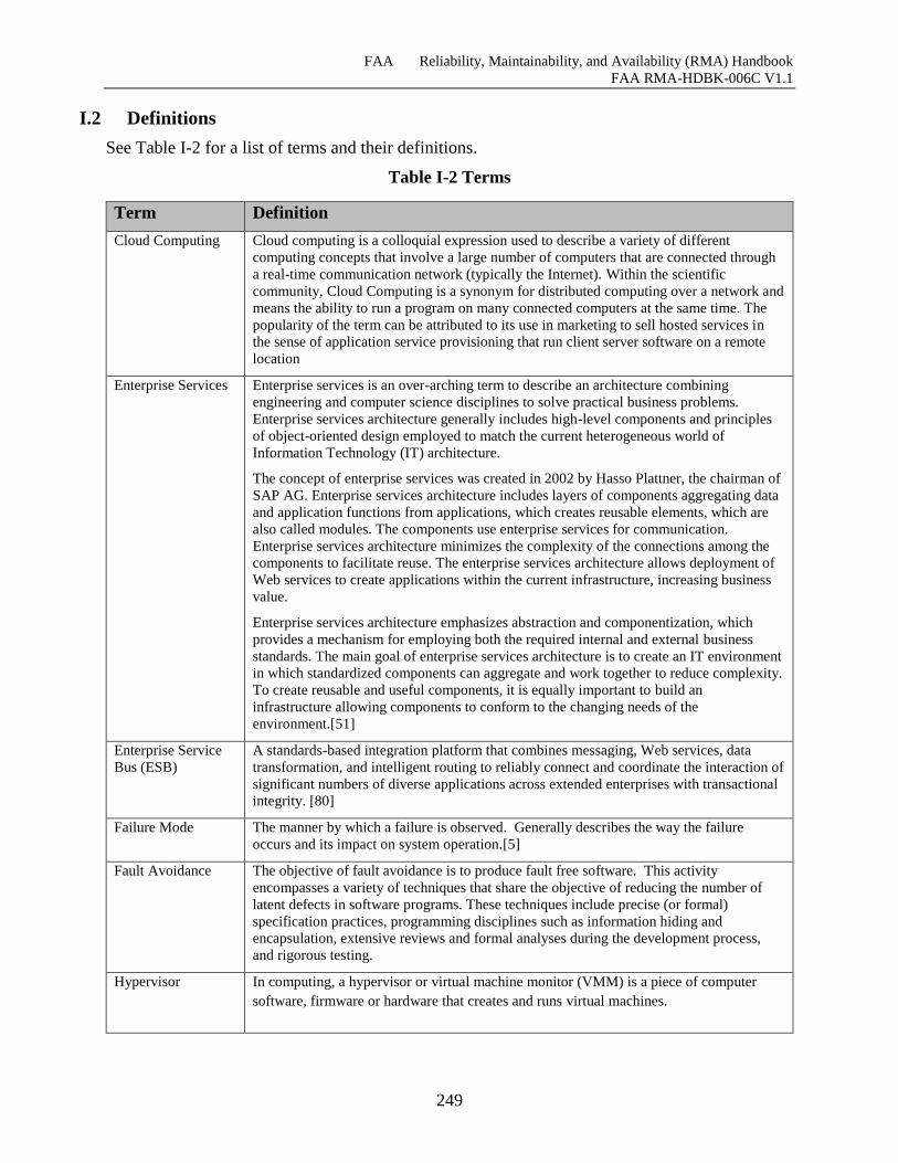
FAA Reliability, Maintainability, and Availability (RMA) Handbook
FAA RMA-HDBK-006C V1.1
249
I.2 Definitions
See Table I-2 for a list of terms and their definitions.
Table I-2 Terms
Term Definition
Cloud Computing Cloud computing is a colloquial expression used to describe a variety of different
computing concepts that involve a large number of computers that are connected through
a real-time communication network (typically the Internet). Within the scientific
community, Cloud Computing is a synonym for distributed computing over a network and
means the ability to run a program on many connected computers at the same time. The
popularity of the term can be attributed to its use in marketing to sell hosted services in
the sense of application service provisioning that run client server software on a remote
location
Enterprise Services Enterprise services is an over-arching term to describe an architecture combining
engineering and computer science disciplines to solve practical business problems.
Enterprise services architecture generally includes high-level components and principles
of object-oriented design employed to match the current heterogeneous world of
Information Technology (IT) architecture.
The concept of enterprise services was created in 2002 by Hasso Plattner, the chairman of
SAP AG. Enterprise services architecture includes layers of components aggregating data
and application functions from applications, which creates reusable elements, which are
also called modules. The components use enterprise services for communication.
Enterprise services architecture minimizes the complexity of the connections among the
components to facilitate reuse. The enterprise services architecture allows deployment of
Web services to create applications within the current infrastructure, increasing business
value.
Enterprise services architecture emphasizes abstraction and componentization, which
provides a mechanism for employing both the required internal and external business
standards. The main goal of enterprise services architecture is to create an IT environment
in which standardized components can aggregate and work together to reduce complexity.
To create reusable and useful components, it is equally important to build an
infrastructure allowing components to conform to the changing needs of the
environment.[51]
Enterprise Service
Bus (ESB)
A standards-based integration platform that combines messaging, Web services, data
transformation, and intelligent routing to reliably connect and coordinate the interaction of
significant numbers of diverse applications across extended enterprises with transactional
integrity. [80]
Failure Mode The manner by which a failure is observed. Generally describes the way the failure
occurs and its impact on system operation.[5]
Fault Avoidance The objective of fault avoidance is to produce fault free software. This activity
encompasses a variety of techniques that share the objective of reducing the number of
latent defects in software programs. These techniques include precise (or formal)
specification practices, programming disciplines such as information hiding and
encapsulation, extensive reviews and formal analyses during the development process,
and rigorous testing.
Hypervisor In computing, a hypervisor or virtual machine monitor (VMM) is a piece of computer
software, firmware or hardware that creates and runs virtual machines.
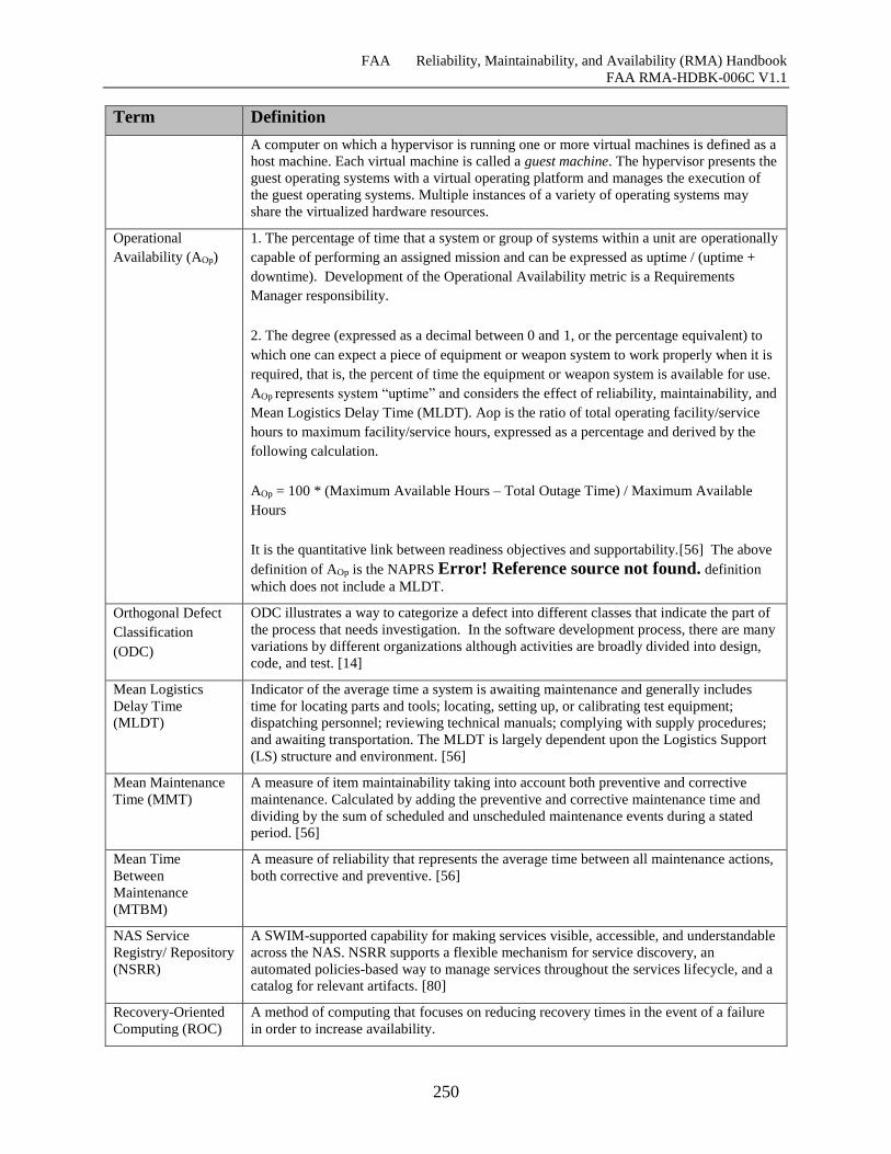
FAA Reliability, Maintainability, and Availability (RMA) Handbook
FAA RMA-HDBK-006C V1.1
250
Term Definition
A computer on which a hypervisor is running one or more virtual machines is defined as a
host machine. Each virtual machine is called a guest machine. The hypervisor presents the
guest operating systems with a virtual operating platform and manages the execution of
the guest operating systems. Multiple instances of a variety of operating systems may
share the virtualized hardware resources.
Operational
Availability (AOp)
1. The percentage of time that a system or group of systems within a unit are operationally
capable of performing an assigned mission and can be expressed as uptime / (uptime +
downtime). Development of the Operational Availability metric is a Requirements
Manager responsibility.
2. The degree (expressed as a decimal between 0 and 1, or the percentage equivalent) to
which one can expect a piece of equipment or weapon system to work properly when it is
required, that is, the percent of time the equipment or weapon system is available for use.
AOp represents system “uptime” and considers the effect of reliability, maintainability, and
Mean Logistics Delay Time (MLDT). Aop is the ratio of total operating facility/service
hours to maximum facility/service hours, expressed as a percentage and derived by the
following calculation.
AOp = 100 * (Maximum Available Hours – Total Outage Time) / Maximum Available
Hours
It is the quantitative link between readiness objectives and supportability.[56] The above
definition of AOp is the NAPRS Error! Reference source not found. definition
which does not include a MLDT.
Orthogonal Defect
Classification
(ODC)
ODC illustrates a way to categorize a defect into different classes that indicate the part of
the process that needs investigation. In the software development process, there are many
variations by different organizations although activities are broadly divided into design,
code, and test. [14]
Mean Logistics
Delay Time
(MLDT)
Indicator of the average time a system is awaiting maintenance and generally includes
time for locating parts and tools; locating, setting up, or calibrating test equipment;
dispatching personnel; reviewing technical manuals; complying with supply procedures;
and awaiting transportation. The MLDT is largely dependent upon the Logistics Support
(LS) structure and environment. [56]
Mean Maintenance
Time (MMT)
A measure of item maintainability taking into account both preventive and corrective
maintenance. Calculated by adding the preventive and corrective maintenance time and
dividing by the sum of scheduled and unscheduled maintenance events during a stated
period. [56]
Mean Time
Between
Maintenance
(MTBM)
A measure of reliability that represents the average time between all maintenance actions,
both corrective and preventive. [56]
NAS Service
Registry/ Repository
(NSRR)
A SWIM-supported capability for making services visible, accessible, and understandable
across the NAS. NSRR supports a flexible mechanism for service discovery, an
automated policies-based way to manage services throughout the services lifecycle, and a
catalog for relevant artifacts. [80]
Recovery-Oriented
Computing (ROC)
A method of computing that focuses on reducing recovery times in the event of a failure
in order to increase availability.
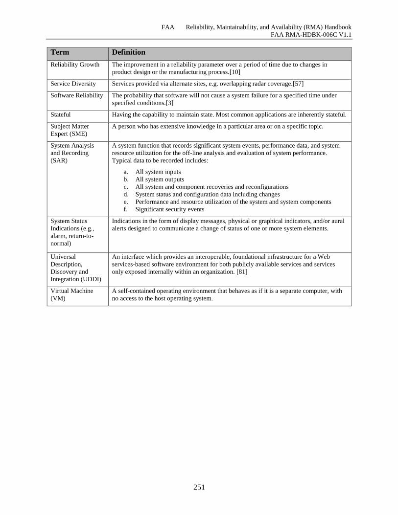
FAA Reliability, Maintainability, and Availability (RMA) Handbook
FAA RMA-HDBK-006C V1.1
251
Term Definition
Reliability Growth The improvement in a reliability parameter over a period of time due to changes in
product design or the manufacturing process.[10]
Service Diversity Services provided via alternate sites, e.g. overlapping radar coverage.[57]
Software Reliability The probability that software will not cause a system failure for a specified time under
specified conditions.[3]
Stateful Having the capability to maintain state. Most common applications are inherently stateful.
Subject Matter
Expert (SME)
A person who has extensive knowledge in a particular area or on a specific topic.
System Analysis
and Recording
(SAR)
A system function that records significant system events, performance data, and system
resource utilization for the off-line analysis and evaluation of system performance.
Typical data to be recorded includes:
a. All system inputs
b. All system outputs
c. All system and component recoveries and reconfigurations
d. System status and configuration data including changes
e. Performance and resource utilization of the system and system components
f. Significant security events
System Status
Indications (e.g.,
alarm, return-to-
normal)
Indications in the form of display messages, physical or graphical indicators, and/or aural
alerts designed to communicate a change of status of one or more system elements.
Universal
Description,
Discovery and
Integration (UDDI)
An interface which provides an interoperable, foundational infrastructure for a Web
services-based software environment for both publicly available services and services
only exposed internally within an organization. [81]
Virtual Machine
(VM)
A self-contained operating environment that behaves as if it is a separate computer, with
no access to the host operating system.
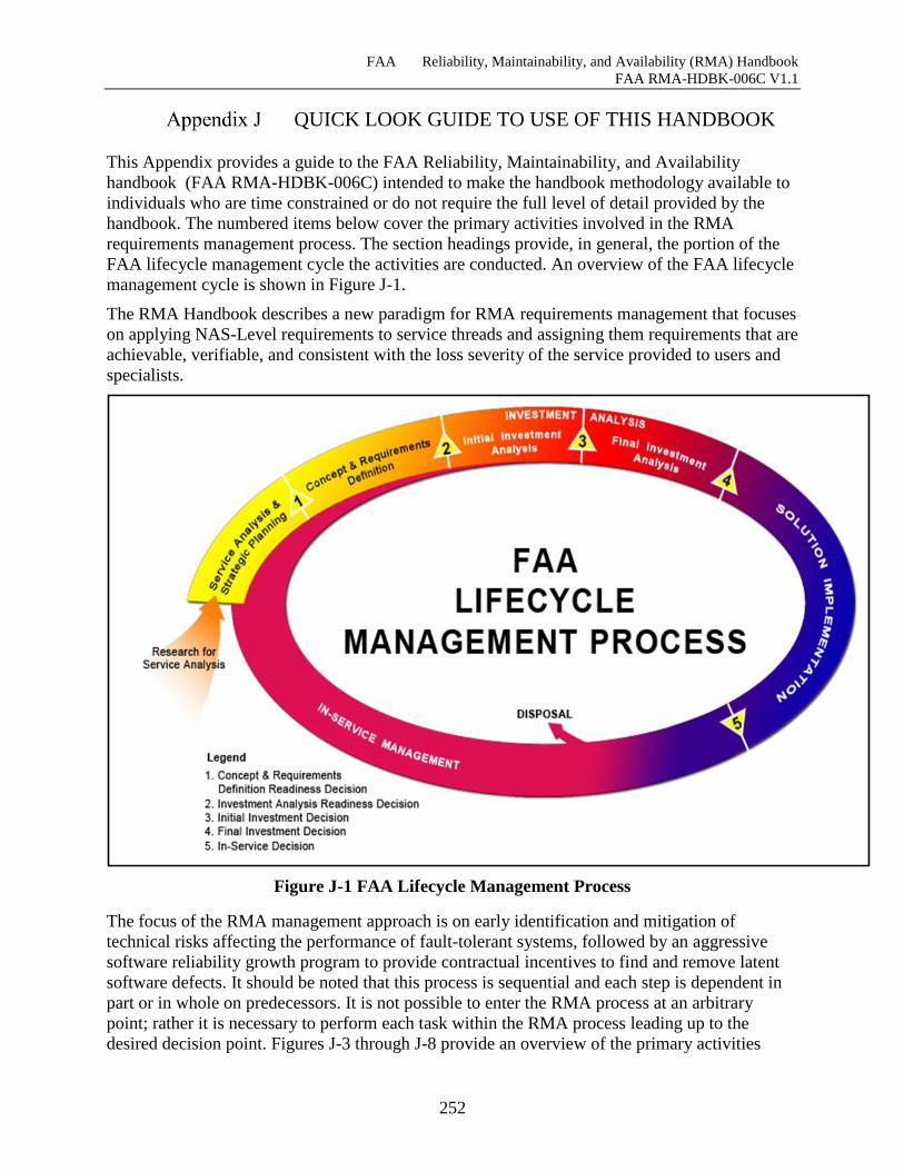
FAA Reliability, Maintainability, and Availability (RMA) Handbook
FAA RMA-HDBK-006C V1.1
252
QUICK LOOK GUIDE TO USE OF THIS HANDBOOK
This Appendix provides a guide to the FAA Reliability, Maintainability, and Availability
handbook (FAA RMA-HDBK-006C) intended to make the handbook methodology available to
individuals who are time constrained or do not require the full level of detail provided by the
handbook. The numbered items below cover the primary activities involved in the RMA
requirements management process. The section headings provide, in general, the portion of the
FAA lifecycle management cycle the activities are conducted. An overview of the FAA lifecycle
management cycle is shown in Figure J-1. The RMA Handbook describes a new paradigm for RMA requirements management that focuses
on applying NAS-Level requirements to service threads and assigning them requirements that are
achievable, verifiable, and consistent with the loss severity of the service provided to users and
specialists.
Figure J-1 FAA Lifecycle Management Process
The focus of the RMA management approach is on early identification and mitigation of
technical risks affecting the performance of fault-tolerant systems, followed by an aggressive
software reliability growth program to provide contractual incentives to find and remove latent
software defects. It should be noted that this process is sequential and each step is dependent in
part or in whole on predecessors. It is not possible to enter the RMA process at an arbitrary
point; rather it is necessary to perform each task within the RMA process leading up to the
desired decision point. Figures J-3 through J-8 provide an overview of the primary activities
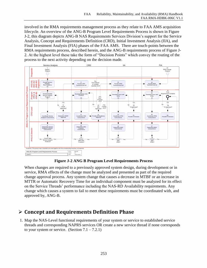
FAA Reliability, Maintainability, and Availability (RMA) Handbook
FAA RMA-HDBK-006C V1.1
253
involved in the RMA requirements management process as they relate to FAA AMS acquisition
lifecycle. An overview of the ANG-B Program Level Requirements Process is shown in Figure
J-2, this diagram depicts ANG-B NAS Requirements Services Division’s support for the Service
Analysis, Concept and Requirements Definition (CRD), Initial Investment Analysis (IIA), and
Final Investment Analysis (FIA) phases of the FAA AMS. There are touch-points between the
RMA requirements process, described herein, and the ANG-B requirements process of Figure J-
2. At the highest level these take the form of “Decision Points” which convey the routing of the
process to the next activity depending on the decision made.
Figure J-2 ANG B Program Level Requirements Process
When changes are required to a previously approved system design, during development or in
service, RMA effects of the change must be analyzed and presented as part of the required
change approval process. Any system change that causes a decrease in MTBF or an increase in
MTTR or Automatic Recovery Time for an individual component must be analyzed for its effect
on the Service Threads’ performance including the NAS-RD Availability requirements. Any
change which causes a system to fail to meet these requirements must be coordinated with, and
approved by, ANG-B.
Concept and Requirements Definition Phase
1. Map the NAS-Level functional requirements of your system or service to established service
threads and corresponding NAPRS services OR create a new service thread if none corresponds
to your system or service. (Section 7.1 – 7.2.1)
Pro
gra
m
Offic
e &
AN
G-B
1
AN
G-B
1
AN
G-B
2
AN
G-B
3
En
gin
ee
rs
Re
qu
este
rC
RD
Le
ad
AN
G-B
Dire
cto
r
AN
G-B
1 P
rog
ram
-Le
ve
l R
eq
uire
me
nts
Pro
ce
ss
Disclaimer: This process map is intended to be read together with the corresponding narratives, not separate.
24Provide fPRD
Technical Kick-off
17
Develop/Concur with
iPRD
25
Develop/Concur with
fPRD
31
Final
Requirements Complete
19Determine iPRD
Concurrence
20
Concur
With
iPRD?
27Determine fPRD
Concurrence
28
Concur
With
fPRD?
author:
version:
status:
1.0ANG-B1 Program-Level Requirements Process
Initial VersionLevel 1
1
Support
Request
ANG-B1
Service Analysis CRD IIA FIA
3
Develop/Update
Service Analysis
Products
5Determine Service Analysis Products
Concurrence
12Determine CRD
ProductsConcurrence
13
Concur
With CRD
Products?
7Determine CRDR
Approval
14Provide IA Readiness
Approval
6
Concur With
Service Analysis
Products?
No Yes No Yes YesNo No Yes
9
Provide CRD
Technical Kick-off
16
Provide iPRD
Technical Kick-off
10Develop/Update CRD
Products
Yes,
Tech Refresh
or Variable
Quantity ACAT
Yes,
Facility
ACAT
8
CRDR
Approved?
15
IAR
Approved?
Yes,
New
Program
ACATYes
NoNo
4
Coordinate Service
Analysis Concurrence
11
Coordinate CRD
Concurrence
2Provide Service
Analysis Req. Guidance
23
fPRD Change
Request
21Provide II Decision
22
II Approved?
18
Coordinate iPRD
Concurrence
26
Coordinate fPRD
Concurrence
No
Yes
29Provide FI Decision
30
FI Approved?
Yes
No
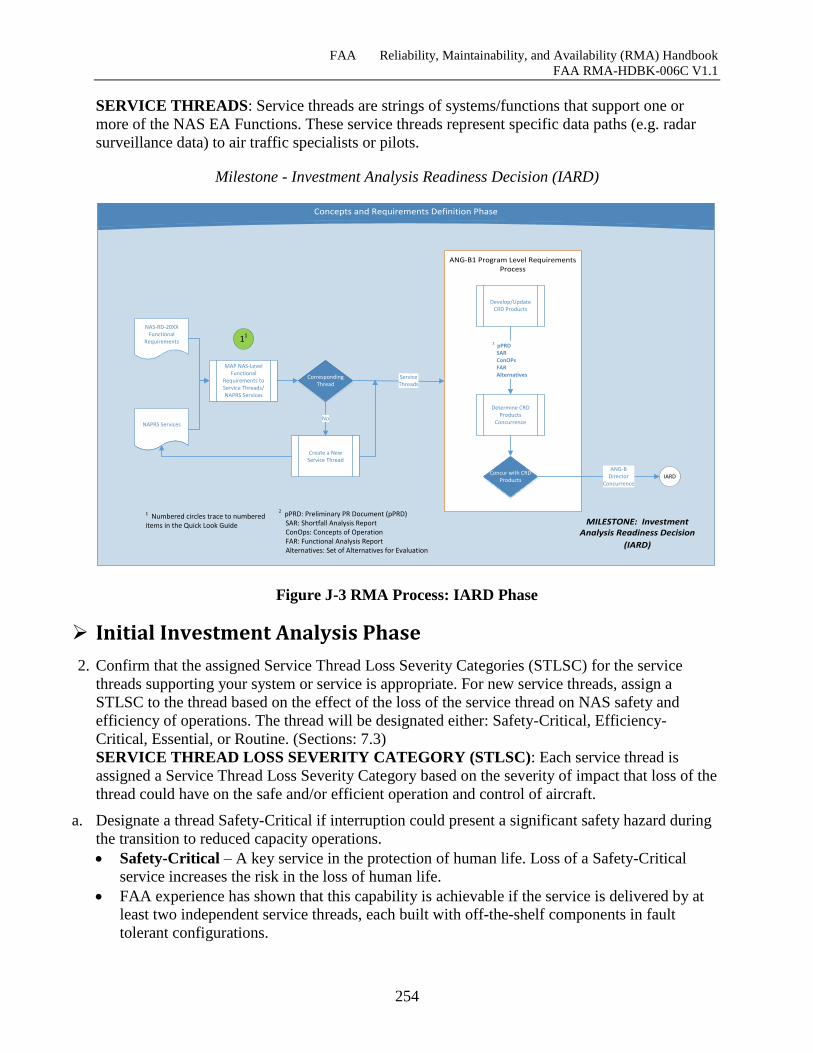
FAA Reliability, Maintainability, and Availability (RMA) Handbook
FAA RMA-HDBK-006C V1.1
254
SERVICE THREADS: Service threads are strings of systems/functions that support one or
more of the NAS EA Functions. These service threads represent specific data paths (e.g. radar
surveillance data) to air traffic specialists or pilots.
Milestone - Investment Analysis Readiness Decision (IARD)
Heading
Concepts and Requirements Definition Phase
ANG-B1 Program Level Requirements Process
MAP NAS-Level Functional
Requirements to Service Threads/NAPRS Services
NAS-RD-20XXFunctional
Requirements
NAPRS Services
CorrespondingThread
ServiceThreads
Create a New Service Thread
No
MILESTONE: Investment Analysis Readiness Decision
(IARD)
ANG-BDirector
ConcurrenceIARD
Develop/Update CRD Products
Concur with CRD Products
Determine CRD Products
Concurrence
2 pPRD SAR ConOPs FAR Alternatives
2 pPRD: Preliminary PR Document (pPRD) SAR: Shortfall Analysis Report ConOps: Concepts of Operation FAR: Functional Analysis Report Alternatives: Set of Alternatives for Evaluation
11
1 Numbered circles trace to numbered items in the Quick Look Guide
Figure J-3 RMA Process: IARD Phase
Initial Investment Analysis Phase
2. Confirm that the assigned Service Thread Loss Severity Categories (STLSC) for the service
threads supporting your system or service is appropriate. For new service threads, assign a
STLSC to the thread based on the effect of the loss of the service thread on NAS safety and
efficiency of operations. The thread will be designated either: Safety-Critical, Efficiency-
Critical, Essential, or Routine. (Sections: 7.3)
SERVICE THREAD LOSS SEVERITY CATEGORY (STLSC): Each service thread is
assigned a Service Thread Loss Severity Category based on the severity of impact that loss of the
thread could have on the safe and/or efficient operation and control of aircraft.
a. Designate a thread Safety-Critical if interruption could present a significant safety hazard during
the transition to reduced capacity operations.
Safety-Critical – A key service in the protection of human life. Loss of a Safety-Critical
service increases the risk in the loss of human life.
FAA experience has shown that this capability is achievable if the service is delivered by at
least two independent service threads, each built with off-the-shelf components in fault
tolerant configurations.
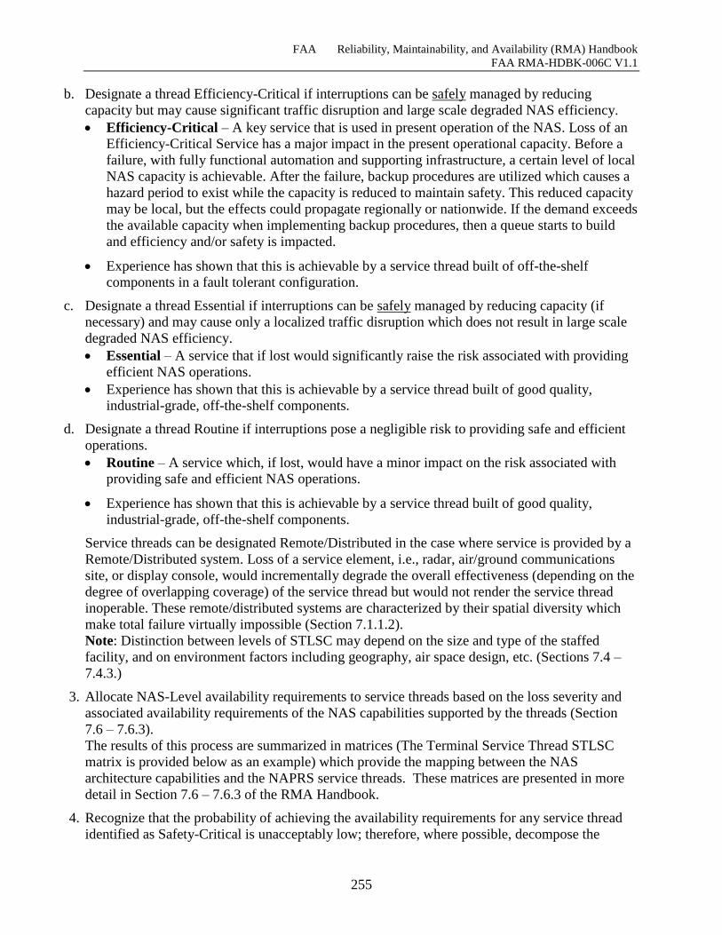
FAA Reliability, Maintainability, and Availability (RMA) Handbook
FAA RMA-HDBK-006C V1.1
255
b. Designate a thread Efficiency-Critical if interruptions can be safely managed by reducing
capacity but may cause significant traffic disruption and large scale degraded NAS efficiency.
Efficiency-Critical – A key service that is used in present operation of the NAS. Loss of an
Efficiency-Critical Service has a major impact in the present operational capacity. Before a
failure, with fully functional automation and supporting infrastructure, a certain level of local
NAS capacity is achievable. After the failure, backup procedures are utilized which causes a
hazard period to exist while the capacity is reduced to maintain safety. This reduced capacity
may be local, but the effects could propagate regionally or nationwide. If the demand exceeds
the available capacity when implementing backup procedures, then a queue starts to build
and efficiency and/or safety is impacted.
Experience has shown that this is achievable by a service thread built of off-the-shelf
components in a fault tolerant configuration.
c. Designate a thread Essential if interruptions can be safely managed by reducing capacity (if
necessary) and may cause only a localized traffic disruption which does not result in large scale
degraded NAS efficiency.
Essential – A service that if lost would significantly raise the risk associated with providing
efficient NAS operations.
Experience has shown that this is achievable by a service thread built of good quality,
industrial-grade, off-the-shelf components.
d. Designate a thread Routine if interruptions pose a negligible risk to providing safe and efficient
operations.
Routine – A service which, if lost, would have a minor impact on the risk associated with
providing safe and efficient NAS operations.
Experience has shown that this is achievable by a service thread built of good quality,
industrial-grade, off-the-shelf components.
Service threads can be designated Remote/Distributed in the case where service is provided by a
Remote/Distributed system. Loss of a service element, i.e., radar, air/ground communications
site, or display console, would incrementally degrade the overall effectiveness (depending on the
degree of overlapping coverage) of the service thread but would not render the service thread
inoperable. These remote/distributed systems are characterized by their spatial diversity which
make total failure virtually impossible (Section 7.1.1.2).
Note: Distinction between levels of STLSC may depend on the size and type of the staffed
facility, and on environment factors including geography, air space design, etc. (Sections 7.4 –
7.4.3.)
3. Allocate NAS-Level availability requirements to service threads based on the loss severity and
associated availability requirements of the NAS capabilities supported by the threads (Section
7.6 – 7.6.3).
The results of this process are summarized in matrices (The Terminal Service Thread STLSC
matrix is provided below as an example) which provide the mapping between the NAS
architecture capabilities and the NAPRS service threads. These matrices are presented in more
detail in Section 7.6 – 7.6.3 of the RMA Handbook.
4. Recognize that the probability of achieving the availability requirements for any service thread
identified as Safety-Critical is unacceptably low; therefore, where possible, decompose the
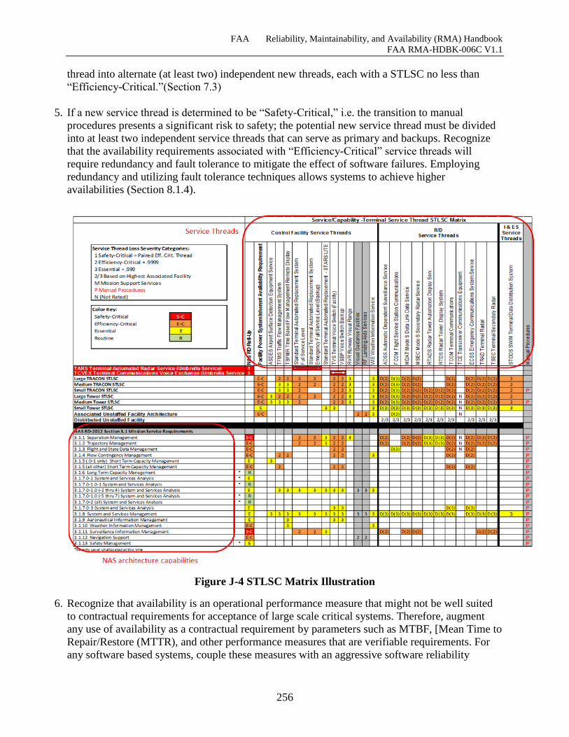
FAA Reliability, Maintainability, and Availability (RMA) Handbook
FAA RMA-HDBK-006C V1.1
256
thread into alternate (at least two) independent new threads, each with a STLSC no less than
“Efficiency-Critical.”(Section 7.3)
5. If a new service thread is determined to be “Safety-Critical,” i.e. the transition to manual
procedures presents a significant risk to safety; the potential new service thread must be divided
into at least two independent service threads that can serve as primary and backups. Recognize
that the availability requirements associated with “Efficiency-Critical” service threads will
require redundancy and fault tolerance to mitigate the effect of software failures. Employing
redundancy and utilizing fault tolerance techniques allows systems to achieve higher
availabilities (Section 8.1.4).
Figure J-4 STLSC Matrix Illustration
6. Recognize that availability is an operational performance measure that might not be well suited
to contractual requirements for acceptance of large scale critical systems. Therefore, augment
any use of availability as a contractual requirement by parameters such as MTBF, [Mean Time to
Repair/Restore (MTTR), and other performance measures that are verifiable requirements. For
any software based systems, couple these measures with an aggressive software reliability
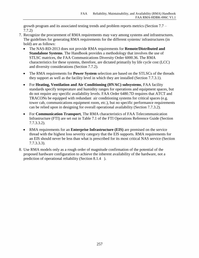
FAA Reliability, Maintainability, and Availability (RMA) Handbook
FAA RMA-HDBK-006C V1.1
257
growth program and its associated testing trends and problem reports metrics (Section 7.7 –
7.7.2)
7. Recognize the procurement of RMA requirements may vary among systems and infrastructures.
The guidelines for generating RMA requirements for the different systems/ infrastructures (in
bold) are as follows:
The NAS-RD-2013 does not provide RMA requirements for Remote/Distributed and
Standalone Systems. The Handbook provides a methodology that involves the use of
STLSC matrices, the FAA Communications Diversity Order 6000.36. The RMA
characteristics for these systems, therefore, are dictated primarily by life cycle cost (LCC)
and diversity considerations (Section 7.7.2).
The RMA requirements for Power System selection are based on the STLSCs of the threads
they support as well as the facility level in which they are installed (Section 7.7.3.1).
For Heating, Ventilation and Air Conditioning (HVAC) subsystems, FAA facility
standards specify temperature and humidity ranges for operations and equipment spaces, but
do not require any specific availability levels. FAA Order 6480.7D requires that ATCT and
TRACONs be equipped with redundant air conditioning systems for critical spaces (e.g.
tower cab, communications equipment room, etc.), but no specific performance requirements
can be relied upon in designing for overall operational availability (Section 7.7.3.2).
For Communication Transport, The RMA characteristics of FAA Telecommunication
Infrastructure (FTI) are set out in Table 7.1 of the FTI Operations Reference Guide (Section
7.7.3.3.2).
RMA requirements for an Enterprise Infrastructure (EIS) are premised on the service
thread with the highest loss severity category that the EIS supports. RMA requirements for
an EIS should never be less than what is prescribed for its most critical NAS service (Section
7.7.3.3.3).
8. Use RMA models only as a rough order of magnitude confirmation of the potential of the
proposed hardware configuration to achieve the inherent availability of the hardware, not a
prediction of operational reliability (Section 8.1.4 ).
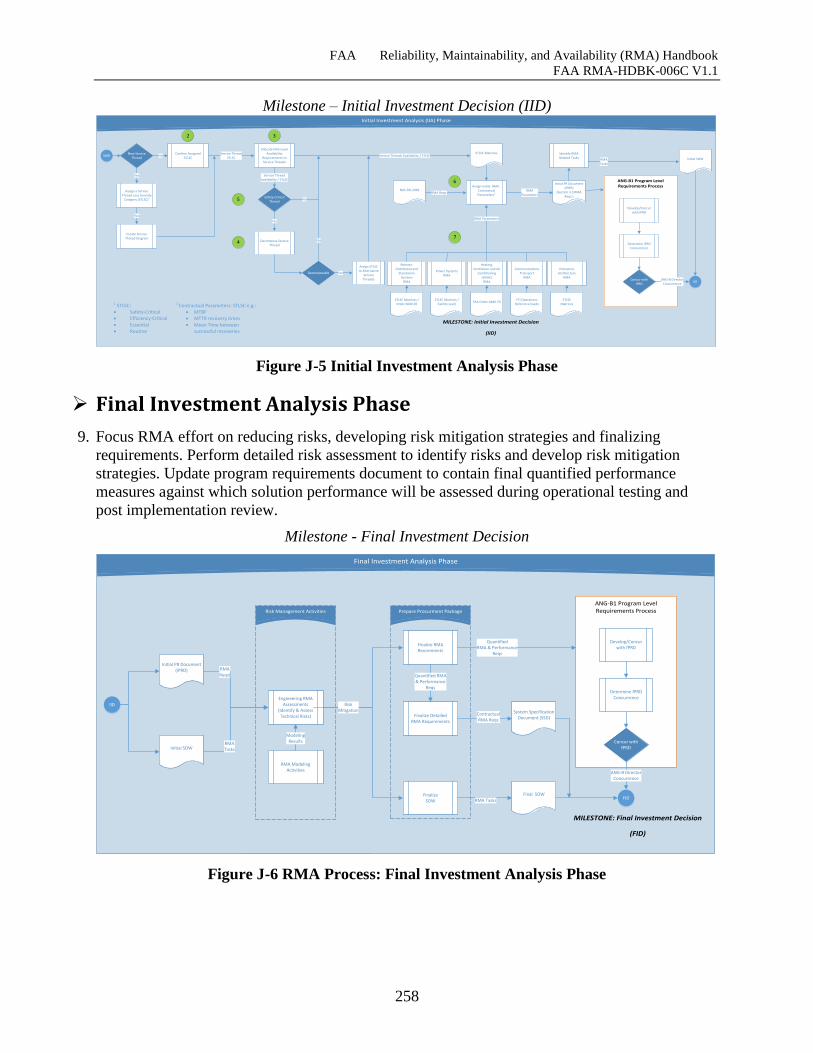
FAA Reliability, Maintainability, and Availability (RMA) Handbook
FAA RMA-HDBK-006C V1.1
258
Milestone – Initial Investment Decision (IID) Initial Investment Analysis (IIA) Phase
ANG-B1 Program Level Requirements Process
Confirm Assigned STLSC
New Service Thread
IID
IARD
Assign a Service Thread Loss Severity
Category (STLSC)1
1 STLSC: Safety-Critical Efficiency-Critical Essential Routine
No
Allocate NAS-Level Availability
Requirements to Service Threads
Service ThreadSTLSC
Service ThreadAvailability / STLSC
STLSC Matrices
Safety-Critical Thread
Decompose Service Thread
Yes
Yes
Assign Initial RMA . Contractual Parameters2
2 Contractual Parameters: STLSC e.g.: MTBF MTTR recovery times Mean Time between
successful recoveries
RMAParameters
Communications Transport
RMA
Remote-Distributed and
Standalone Systems
RMA
Power SystemsRMA
Heating, Ventilation and Air
Conditioning (HVAC)
RMA
Enterprise Architecture
RMA
RMA Parameters
STLSC Matrices /Order 6000.36
STLSC Matrices /Facility Level
FAA Order 6480.7DFTI Operations
Reference GuideSTLSC
Matrices
NAS-RD-20XXRMA Reqs.
Decomposable
Assign STLSC to Alternative
Service Threads
Yes
MILESTONE: Initial Investment Decision
(IID)
Initial PR Document (IPRD)
(Section 3.3 RMA Reqs.)
No
Service Threads Availability / STLSC
No
ANG-B DirectorConcurrence
Create Service Thread Diagram
Yes
RMATasks
Identify RMA Related Tasks Initial SOW
2 3
4
5
6
7
Develop/Concur with iPRD
Determine iPRD Concurrence
Concur with iPRD
Figure J-5 Initial Investment Analysis Phase
Final Investment Analysis Phase
9. Focus RMA effort on reducing risks, developing risk mitigation strategies and finalizing
requirements. Perform detailed risk assessment to identify risks and develop risk mitigation
strategies. Update program requirements document to contain final quantified performance
measures against which solution performance will be assessed during operational testing and
post implementation review.
Milestone - Final Investment Decision
Risk Management Activities
Final Investment Analysis Phase
ANG-B1 Program Level Requirements ProcessRisk Management Activities Prepare Procurment Package
FID
IID
MILESTONE: Final Investment Decision
(FID)
Final SOW
System Specification Document (SSD)
Finalize RMAReuirements
Finalize Detailed RMA Requirements
FinalizeSOW
QuantifiedRMA & Performance
Reqs
Quantified RMA & Performance
Reqs
Contractual RMA Reqs
Engineering RMA Assessments
(Identify & Assess Technical Risks)
RMA Tasks
Initial PR Document (iPRD) RMA
Reqs)
Initial SOW
RMA Modeling Activities
ModelingResults
Develop/Concur with fPRD
Determine fPRD Concurrence
Concur with fPRD
ANG-B DirectorConcurrence
RiskMitigation
RMATasks
Figure J-6 RMA Process: Final Investment Analysis Phase
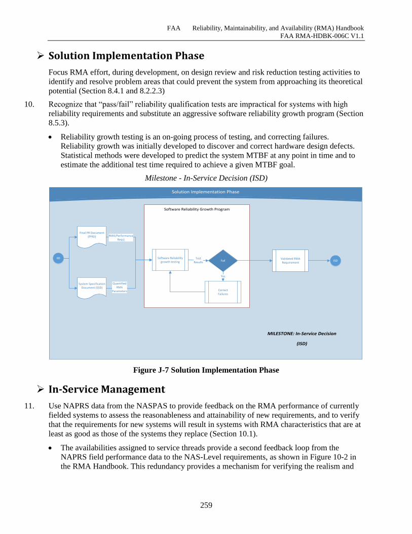
FAA Reliability, Maintainability, and Availability (RMA) Handbook
FAA RMA-HDBK-006C V1.1
259
Solution Implementation Phase
Focus RMA effort, during development, on design review and risk reduction testing activities to
identify and resolve problem areas that could prevent the system from approaching its theoretical
potential (Section 8.4.1 and 8.2.2.3)
10. Recognize that “pass/fail” reliability qualification tests are impractical for systems with high
reliability requirements and substitute an aggressive software reliability growth program (Section
8.5.3).
Reliability growth testing is an on-going process of testing, and correcting failures.
Reliability growth was initially developed to discover and correct hardware design defects.
Statistical methods were developed to predict the system MTBF at any point in time and to
estimate the additional test time required to achieve a given MTBF goal.
Milestone - In-Service Decision (ISD)
Solution Implementation Phase
Software Reliability Growth Program
IID
MILESTONE: In-Service Decision
(ISD)
Software Reliability growth testing
Final PR Document (fPRD) RMA/Performance
Reqs)
System SpecificationDocument (SSD)
QuantifiedRMA
Parameters
Fail
CorrectFailures
TestResults
Yes
Validated RMA Requirement
ISD
Figure J-7 Solution Implementation Phase
In-Service Management
11. Use NAPRS data from the NASPAS to provide feedback on the RMA performance of currently
fielded systems to assess the reasonableness and attainability of new requirements, and to verify
that the requirements for new systems will result in systems with RMA characteristics that are at
least as good as those of the systems they replace (Section 10.1).
The availabilities assigned to service threads provide a second feedback loop from the
NAPRS field performance data to the NAS-Level requirements, as shown in Figure 10-2 in
the RMA Handbook. This redundancy provides a mechanism for verifying the realism and
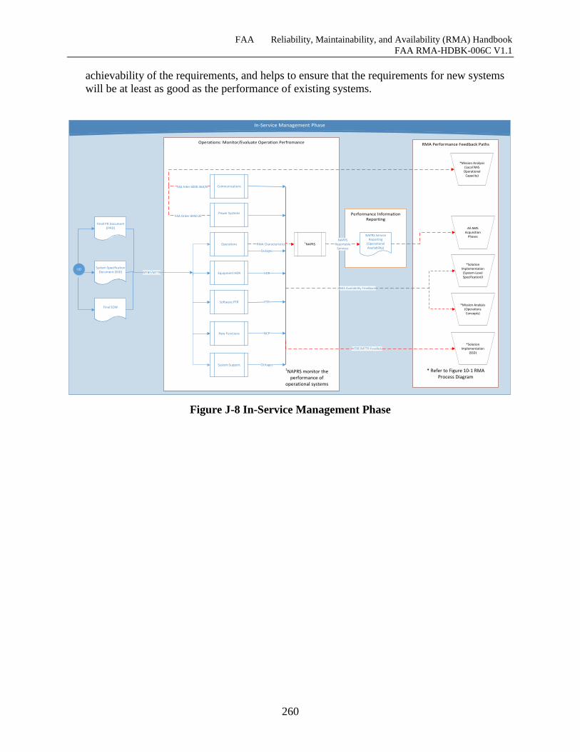
FAA Reliability, Maintainability, and Availability (RMA) Handbook
FAA RMA-HDBK-006C V1.1
260
achievability of the requirements, and helps to ensure that the requirements for new systems
will be at least as good as the performance of existing systems.
In-Service Management Phase
Operations: Monitor/Evaluate Operation Perfromance RMA Performance Feedback Paths
Performance Information Reporting
ISD
Finall PR Document (iPRD)
MTBF/MTTR
Final SOW
New Functions
Communications
Power Systems
Operations
System Support
Equipment HDR
Software PTR
HDR
PTR
NCP
Outages
OUtages
FAA Irder 6000.36A/B
FAA Order 6950.2E
*Solution Implementation
(SSD)MTBF/MTTR Feedbck
*Mission Analysis(Local NAS
Operational Capacity)
*Solution Implementation
(System-LevelSpecification)l
* Refer to Figure 10-1 RMA Process Diagram
*Mission Analysis (Operations Concepts)
NAS Availability Feedback
System SpecificationDocument (SSD)
NAPRS Service Reporting
(Operational Availability)
1NAPRSRMA CharacteristicsNAPRS
ReportableServices
All AMS Acquisition
Phases
1NAPRS monitor the performance of
operational systems
Figure J-8 In-Service Management Phase