reliability performance in gps receivers - · pdf filepage 1 reliability performance in gps...
TRANSCRIPT
Page 1
RELIABILITY PERFORMANCE IN GPS RECEIVERS AND THE NATUREOF THEIR FAILURES: PLANNING TO LIVE WITH REALISTIC FAILURE
RATES IN SATELLITE NAVIGATION SYSTEM RECEIVERS.
Sarah Sharkey, National Air Traffic Services Limited, London, UKRolf Johannessen, Lambourne Navigation Limited, Harlow, Essex, UK.
A paper given to NAV96, London, 5-6 November 1996
ABSTRACT
The National Air Traffic Services (NATS) in London require data on the performance likely to be achievedby the navigation system on board aircraft flying in UK airspace. To that end the performance of threedifferent GPS receiver types (all designed for aviation use) has been examined. This paper details the resultof that work. The achieved Mean Time Between Failures (referred to here as “Outages”) MTBO ispresented along with the nature of some of the failures that have been encountered. The paper concludeswith the operational implication of the findings.
BIOGRAPHIES
Sarah Sharkey obtained her PhD from Liverpool University. She joined National Air Traffic Services Ltdin 1993 and has worked on a number of ATM system projects. More recently she has managed research inboth Surveillance and Navigation areas, including GNSS projects. She is an Associate Member of the IEE.
Rolf Johannessen obtained his PhD from London University. A period developing instrument landingsystems for aircraft was followed by several years developing computer systems. In 1969 he joined theresearch laboratory which is now known as Nortel in Harlow where for many years he was manager of thenavigation department. In 1994 he left to form his own company, Lambourne Navigation Limited, whereas Director he now undertakes consultancy work in Communication, Navigation and Surveillance. Rolf is aFellow of IEE, a Fellow of RIN and a Member of the ION.
1 INTRODUCTION
The achievement of good safety is crucial for aviation: every system which the UK approves for aviationhas to undergo a formal scrutiny which leads to the preparation of a “safety case”. This is a system ofdocumentation which demonstrates that the system is safe to use. A good insight into the failure modes is apre-requisite. This allows the safety case to document the steps taken to ensure that the effect of suchfailures is controlled in a manner that adequately safeguards the aircraft. As part of the process of gaininginsight into failure modes in GPS NATS has undertaken two projects which are described in this paper.The first project examined the reliability data derived from a GPS receiver fitted in a revenue-earningBoeing 747-400. This project ran during the period April 1994 to December 1995, when it was closedpending the availability of better GPS equipment. The second project involved the data collection from 4GPS receivers located at a London airport with data collected from late 1995 up to the present time.Important lessons can be learned from both these projects.
2 THE FLYING LABORATORY
The growing interest in using GPS for navigation of aircraft made it necessary for NATS, in common withother administrations, to start gathering data on the performance of GPS receivers that were intended foraviation use. As part of the Automatic Dependent Surveillance (ADS) programme undertaken by NATS, itbecame possible to gain access to the output data from a GPS receiver installed on board one of the BritishAirways B747-400 aircraft. This was very attractive for two reasons:
(a) the aircraft followed tracks and manoeuvred in a manner typical of civil aviation; it was not restrainedin operating range or region as is common with research aircraft,
(b) the aircraft flew at all times during night and day and was not therefore constrained by the hours ofwork employed by typical laboratories.

Page 2
The data from the GPS receiver's output terminals was sent to the aircraft's satellite communicationsterminal, from there it was transmitted via an INMARSAT communications satellite to the Ground EarthStation at Goonhilly and passed to the Air Traffic Management Development Centre (ATMDC) atBournemouth airport in South England. ATMDC extracted the relevant data which was passed toLambourne Navigation Limited (LNL) for analysis.
3 THE NORMAL DATA AVAILABLE
ATMDC are able to request the aircraft to transmit different data groups; one such combination of “good”data is illustrated by Figure 1 containing a sample transmission at approximate time 1848 UTC. Thedownlink message comprises first the data from the aircraft flight management system, and then the datafrom the aircraft GPS receiver, which is not connected to the FMS. The aircraft is at FL310 and south ofequator. A small difference will be observed between FMS and GPS positions: this is quite normal sincethe FMS [position] is derived from an inertial system which drifts with time. GPS on the other hand has nosuch long term drift, and is generally more accurate.
A study of GPS receiver performance can be accomplished by considering several aspects:
(a) examination of the difference between the FMS and GPS positions,(b) examination of the change in GPS position with time, knowing that the aircraft position changes
with time in a fairly confined manner (it cannot for instance move 100 miles in one minute),(c) examination of the “sanity” of the GPS position (in some cases for instance the GPS receiver
claimed to be at north latitude 180 degrees).
For the purpose of this analysis it was concluded that there was a “GPS outage” if the data stream asreceived at LNL had any of the following symptoms:
(i) GPS integrity flag was set “invalid”,(ii) GPS latitude >+90 degrees or <-90 degrees,(iii) GPS longitude >+179 degrees or <-179 degrees,(iv) GPS altitude <-2,000 feet or> 50,000 feet,(v) GPS height rate >250 feet/minute when the baro height showed the aircraft to be in level flight,(vi) the GPS 2-D position differed from the FMS position by >5 n miles.
4 DATA VOLUME
It will be apparent from this that the data base is substantial and is collected from aviation trajectories thatare representative of the way GPS is expected to be used in earnest. The authors are not aware of anycomparable comprehensive examination of GPS data from revenue operating flights, though reference hasbeen made earlier [1] to some of the first results from this project.
5 RESULTS OF THE ANALYSIS
The total number of ADS downlinked messages examined from a GPS point of view amounted to 34,419.These came from 150 flight legs, the first on 6th April 1994, and the last on 13th December 1995. The datawas derived from 819.7 flight hours though in many cases the flights were longer. The 819.7 representsthe time during which GPS data was available.
The flights were of a wide variety, including long flights like London to Mexico City which are about 12hours, and short flights like Sao Paulo to Rio which are about one hour. The data includes samples fromflights between the UK and the US West Coast (eg Los Angeles), the US East Coast (eg Boston), SouthAmerica as far south as Buenos Aires, South Africa as far south as Cape Town and Bangkok in Asia(though during this last study the coverage of the INMRSAT satellite limited data collection to the westernpart of the flight). In many cases recording started soon after the aircraft was airborne and continued untilshortly before landing, though the majority of the data are taken from cruising altitudes. Some of the flightstook place during daylight hours while others were during the night. The downlinked messages weredivided into three different groups:

Page 3
(a) messages which had the GPS integrity flag set “INVALID”,(b) messages which had the GPS integrity flag set “VALID” but where there was found to be an outage
defined by (ii) to (vi) at section 3 above,(c) messages which had the integrity flag set “VALID” and where no outage could be observed, ie the
data was “good”.
Based on this division the results were:
Group No of messages % of total(a) “Invalid” type outages 759 2.21(b) “Valid” type outages 487 1.41(c) “Valid” and good 33173 96.38
Total 34419 100.00
In all cases the erroneous messages came as a continuous block. In most cases the fault cleared itself inflight without the flight crew taking any action, but in a few cases the fault persisted until the aircraftlanded, or until data recording ended. The total number of such outage blocks found in this analysis was28. The total outage time was 2260 minutes, giving a mean outage time of 81 minutes per outage, duringwhich the aircraft would have moved over 600 miles (assuming a mean ground speed of 450 knots).
For part of this project the only flights that were analysed in detail from the GPS point of view were thoseknown to have a GPS problem. However, in order to get the order of magnitude of Mean Time BetweenOutages (MTBO), there was a substantial period during which all flights containing GPS data wereanalysed whether there was a failure or not. That analysis showed 15 outage blocks with a MTBO of 54.6flying hours.
6 DISCUSSION OF MALFUNCTIONS
There is not, and is unlikely ever to be, uncontroversial evidence that the cases cited as “outages” are due tofailures in the avionics or in the signals-in-space. What is certain is that an Air Traffic Management systemcannot be based on position reports in which more than 3% of the messages hold a useless GPS positionreport. In that sense it does not matter much whether the origin of the failures lies in the GPS signals-in-space, the receiver or in the communication system that brings the data to the ATC unit. In order to seesome of the implications, however, it is valuable to examine some of the characteristics of these failures.
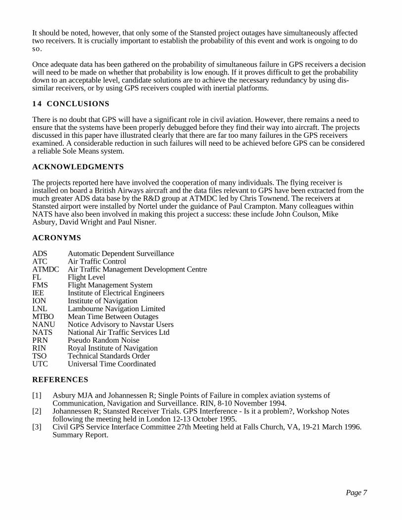
One example is an extract of part of the data stream associated with the outage that took place 30th April1994 while the aircraft was operating a flight from Nairobi to London. That data stream contained theinformation given at Figure 2.
At 2305 UTC the GPS data was good. At 2306 it was invalid and continued to be so until 2315 UTC(indicated by the line of asterisks). At 2316 and 2317 it claimed to be valid but was clearly in error with analtitude below sea level and latitude and longitude seriously wrong, as can be seen by comparing GPS andFMS positions.
The following summarises some of the findings concerning all the 28 outages.
(a) At no time was the GPS receiver repaired. The problems seen are therefore either an intermittency inthe receiver hardware,or a software problem.
(b) In 18 of the 28 failure cases the outage commenced during the time period between 2200 UTC and2400 UTC Saturday night. This is 1.2% of the week for 64% of the cases. This is clearly not arandom failure but shows some systematic problem likely to be linked to inadequately debuggedsoftware. It will be appreciated that in GPS the time is defined in terms of week number, andseconds into that week measured from midnight Saturday/Sunday. Thus candidate explanationsinclude problems with the resetting of the GPS receiver's “Z-counter”, or problems with mismatchbetween the week number in the Almanac and Ephemeris data fields. The nine most recent failurestook effect

Page 4
Saturday 06.05.95 at 2256 UTCSaturday 13.05.95 at 2304 UTCSaturday 03.06.95 at 2302 UTCSunday 04.06.95 at 0352 UTCSaturday 17.06.95 at 2305 UTCSaturday 12.08.95 at 2304 UTCSaturday 14.10.95 at 2243 UTCSaturday 25.11.95 at 2305 UTCSunday 26.11.95 at 1236 UTC
(c) During the period considered the almanac generally had a Time of Applicability (ToA) of 32768seconds. This is the time reference used in the almanac portion of the data stream coming from thesatellites, and is defined as the number of seconds from midnight Saturday/Sunday in the week inquestion, 32768 seconds corresponds, therefore, to about 0906 UTC on Sunday morning.However, at least 5 of the cases arose during a week with a different ToA. This is considered toosmall a sample to say whether this link is significant or not.
(d) The possibility of a link with interference was explored in many cases. For instance, the geographicregion in which the outage commenced was explored for ATC communications frequencies thatmight have a sub-harmonic of the GPS Li frequency. The locations where the GPS data were firstfound to be bad in the above 9 cases were 32N 07E, 41N 10W, 33N 07E, 43N 05E, 50N 100W,06N 08E, 45N 07E, 25N 94W and 61N 27W. These clearly represent a good spread of locations.Out of the 28 cases where a failure arose, some repeated the location, like the first and third above.
(e) The satellite communications link also enables the captain to talk with ATMDC Since there was apossibility that the problem could have been caused by these calls, the time of incident was comparedto the time of those voice transmissions, a time taken from an itemised invoice from thetelecommunication company. No correlation could be found to link the cases, though it may havebeen a factor in some of the cases.
(f) It is not known whether any of the outages were linked to a circuit breaker being operated on theaircraft, though the symptoms of the failures suggest the probability of this being the cause is verysmall.
7 PROJECT SWITCH OF EMPHASIS
When this project started this GPS receiver was the only one installed on a revenue-earning aircraft whichwas also accessible to NATS. It was however not a TSO-approved receiver. Such enhanced receivers havegradually been becoming available and during 1995 the attention of NATS began to switch to a betterreceiver. It has not yet been possible to install such a receiver on the aircraft fitted with ADS, though themost beneficial way of doing so is being actively considered. Meanwhile the portion of the GPS analysisassociated with this older receiver was concluded at the end of 1995.
However, during 1995 4 TSO-approved GPS receivers were procured and installed in a fixed location atLondon's Stansted airport where they were arranged to log their output regularly to computers forsubsequent analysis.
8 STANSTED SYSTEM DESCRIPTION
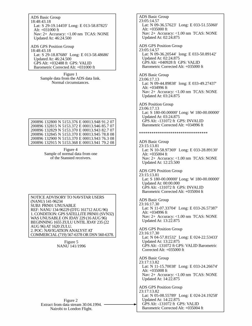
The four receivers comprise two receivers from each of 2 different manufacturers. As it matters not fromthe project point of view who those manufacturers are, they are referred to as receivers 1A, 1B, 2A and2B, with A and B in each case being as identical as possible. Each of the receivers is connected to its ownantenna and all antennas are mounted on a common ground plane which is well above the buildings near-by. There is therefore no significant low elevation obstruction for any of the antennas. The multipathenvironment is good compared to what might be expected in most locations on a busy airport or on anaircraft.
The receivers are fed from two 13.5 volt supplies and each receiver is connected to its own PC. There wasno altitude input to the receivers. Figure 3 illustrates the general arrangement.
The equipment is installed in an air-conditioned building.

Page 5
9 THE DATA AVAILABLE
A short sample of “good” data from one of the receivers is at Figure 4.
This data was recorded on the 20th August 1996 for a short period from 1328 UTC. The interval betweensuccessive samples stored is nominally 15 seconds, though the receivers produce data more frequently thanthat. The time of day is followed by the latitude and longitude of the receiver, the altitude and the number ofsatellites being tracked.
The data is studied to identify “outages” which, in this case, are defined as being periods where more than2 records either
(a) contained no 2-D position, or(b) contained an output position which differed from true position by more than 1 km. These outages are
defined differently from those examined for the aircraft for two reasons. First, the precise position ofthe Stansted receivers is known. Second, a preliminary examination of the Stansted data hadsuggested that an absence of position output had featured and therefore needed further examination.It was therefore decided that focusing on the absence of 2-D position, along with the precision whenthe position was present, constituted the aspects it would be most cost-effective to examine.
1 0 DATA VOLUME
After a shake-down period the system commenced recording for analysis purposes on 22nd August 1995.The data reported in this paper covers results up to 21st August 1996. During the intervening period therehave been a few short periods when the equipment was off due to modifications of the equipment room,and due to a failure in one GPS antenna and one computer used for logging. Apart from these cases therecording has been virtually continuous.
During the period analysed the equipment recorded for a period of 31,604.1 equipment running hours andprovided 7,584,984 records of latitude and longitude. It represents, therefore, a considerable volume ofdata which enables a reliable estimate of long term performance. The start of this experiment wasannounced to RIN at the Interference Workshop in October 1995 [2].
1 1 RESULTS OF THE ANALYSIS
During the same period there were 20 outages which lead to a Mean Time Between Outages (MTBO) of1,580.2 hours. The outages were spread fairly evenly between the receivers; there were 7, 4, 5 and 4outages for each of receivers 1A, 1B, 2A and 2B respectively. The one faulty antenna referred to above isnot included in this since it is not clear whether that antenna was in fact faulty from the start.
1 2 DISCUSSION OF MALFUNCTIONS
The site is un-manned so that no-one watches either the receivers or the environment as the malfunctionsarise. It is not, therefore, and will never be, absolutely certain that the “outages” that appear in the recordeddata stream are due to a malfunction in the receiver. An uncertainty arises because there has been a numberof violent thunderstorms in the Stansted area leading to severe mains transients. In some cases the receiversfailed to operate at a time when such transients or mains failures occurred. Where this is known to havebeen the cause, those outages have not been included. However, it may be that some of the 20 referred toare also linked to such a transient and are therefore not strictly a receiver failure. It is a question, therefore,of analysing the data, looking at the symptoms, comparing the receivers with each other and examiningabnormalities in signals-in-space as noticed through the NANU system. An example of the kind ofdetective work is the last 5 outages that were experienced by receiver 1A. These took place on 5 days aftereach other as follows:
17.08.96 at 0122 UTC for 10 samples18.08.96 at 0118 UTC for 14 samples19.08.96 at 0114 UTC for 15 samples20.08.96 at 0110 UTC for 13 samples

Page 6
21.08.96 at 0106 UTC for 3 samples
It will be observed that the “outage” arose approximately 4 minutes earlier each day. As this is the amountby which the satellites advance their orbit each day it is a very strong indicator that this failure is systematic.On the 16th and the 22nd August there was no problem. A link to the probable cause was found in NANU141 which states that PRN01 was unusable. This NANU is shown in full in Figure 5.
PRN01 was visible to the site on these occasions with an elevation angle of around 42 degrees. An unusualbehaviour of that satellite could therefore affect the receiver. However, the NANU suggests there was aproblem in the morning of 17, 18, 19, 20, 21 and 22nd August. Receiver 1A failed on the first 5 days butnot the last. Receiver 1B did not fail at all. Just why the receivers reacted differently is not known. It maybe linked to the nature of the satellite malfunction, combined with the two receivers holding differentalmanacs. Unfortunately the NANUs do not as a rule give details of the nature of the problem. It wouldcertainly be helpful if there was information about the kind of malfunction, such additional information wasrequested in [3]. The goal of this work is, however, not to identify the specific place in the receiver wherethe problem is located, rather, it is to establish how often a TSO approved receiver might be expected tomisbehave.
It was noted above that these receivers in their current configuration are not provided with an altitude input.if they had been so provided then 4 satellites might have been sufficient to estimate position. However, thefact remains that one of the two receivers was only able to track 4 satellites when the other tracked 6;clearly, therefore, there was a malfunction.
A particular objective of this project is to establish the probability that two identical receiverssimultaneously encounter a problem such that redundancy in a dual installation is lost. Such a situationarose on 18 October 1995 in the period between 1600 UTC and 1700 UTC. During this period receivers2A and 2B displayed considerable abnormalities. Receiver 2A had 5 outages while receiver 2B had 4outages. In each case the receivers recovered without manual intervention. According to NANUs 223 and224 both PRNs 26 and 12 were causing problems at this time. Nevertheless receivers 1A and 1B wereoperating normally. This case on 18 October was the only occasion when two receivers weresimultaneously displaying an outage.
1 3 DISCUSSION OF SOME OF THE RESULTS AND OPERATIONAL IMPLICATIONS
A receiver installed on an aircraft which experiences vibration and large thermal variations might beexpected to yield a performance which is less favourable than that of a receiver which is located on theground in an air-conditioned room. However, the environmental conditions on the B747 are unlikely todiffer substantially from that for which the receiver was designed. A comparison between the one airborneand the 4 located on the ground is therefore not unreasonable. A considerable improvement in reliabilityperformance is observed with the receivers located at the airport. Nevertheless a MTBO of 1,580 hours isextremely poor. Even if a few of the outages were in fact caused by environmental problems such as powertransients or lightning strikes close by, rather than by bad receiver design, this would still leave aperformance considerably worse than that expected from other modern electronics.
It may be argued that data derived from non-TSO approved equipment (i.e. data recorded from the Boeing747) should be disregarded when it comes to designing for airspace safety. The counter argument must bethat if any avionics manufacturer has in place an effective quality control system. then he is unlikely toallow out through his factory gates any system with a MTBO of 54.6 hours, as was the failure rate foundfor the aircraft receiver reported in section 5 of this paper. This suggests that the programme has shown upan undue haste in implementing GPS in civil aviation.
The presence of systematic errors that are triggered by unusual, but in-specification, signals-in-spaceevents is important since these malfunctions have the potential to affect multiple receivers simultaneously.In particular, the Saturday/Sunday problem encountered by the first of the receivers discussed was of sucha nature that multiple identical receivers would be highly likely to fall simultaneously. This would mean thatthe failure protection achievable through redundancy would offer no protection at all. This would beextremely serious in a busy volume of airspace. The seriousness is further increased in an environmentwhere surveillance is effected through a GPS-dependent surveillance system.
Page 7
It should be noted, however, that only some of the Stansted project outages have simultaneously affectedtwo receivers. It is crucially important to establish the probability of this event and work is ongoing to doso.
Once adequate data has been gathered on the probability of simultaneous failure in GPS receivers a decisionwill need to be made on whether that probability is low enough. If it proves difficult to get the probabilitydown to an acceptable level, candidate solutions are to achieve the necessary redundancy by using dis-similar receivers, or by using GPS receivers coupled with inertial platforms.
1 4 CONCLUSIONS
There is no doubt that GPS will have a significant role in civil aviation. However, there remains a need toensure that the systems have been properly debugged before they find their way into aircraft. The projectsdiscussed in this paper have illustrated clearly that there are far too many failures in the GPS receiversexamined. A considerable reduction in such failures will need to be achieved before GPS can be considereda reliable Sole Means system.
ACKNOWLEDGMENTS
The projects reported here have involved the cooperation of many individuals. The flying receiver isinstalled on board a British Airways aircraft and the data files relevant to GPS have been extracted from themuch greater ADS data base by the R&D group at ATMDC led by Chris Townend. The receivers atStansted airport were installed by Nortel under the guidance of Paul Crampton. Many colleagues withinNATS have also been involved in making this project a success: these include John Coulson, MikeAsbury, David Wright and Paul Nisner.
ACRONYMS
ADS Automatic Dependent SurveillanceATC Air Traffic ControlATMDC Air Traffic Management Development CentreFL Flight LevelFMS Flight Management SystemIEE Institute of Electrical EngineersION Institute of NavigationLNL Lambourne Navigation LimitedMTBO Mean Time Between OutagesNANU Notice Advisory to Navstar UsersNATS National Air Traffic Services LtdPRN Pseudo Random NoiseRIN Royal Institute of NavigationTSO Technical Standards OrderUTC Universal Time Coordinated
REFERENCES
[1] Asbury MJA and Johannessen R; Single Points of Failure in complex aviation systems ofCommunication, Navigation and Surveillance. RIN, 8-10 November 1994.
[2] Johannessen R; Stansted Receiver Trials. GPS Interference - Is it a problem?, Workshop Notesfollowing the meeting held in London 12-13 October 1995.
[3] Civil GPS Service Interface Committee 27th Meeting held at Falls Church, VA, 19-21 March 1996.Summary Report.
Barometric Corrected Alt: +031000 ft
ADS Basic Group
ADS Basic Group23:05:14.57
Lat: N 09-36.57623' Long: E 033-51.55060'Alt: +035000 ftNav: 2+ Accuracy: <1.00 nm TCAS: NONEUpdated At: 02:24.875
ADS GPS Position Group23:05:14.57
Lat: N 09-36.20544' long: E 033-50.89142'Updated At: 02:24.875GPS Alt: +040928 ft GPS: VALIDBarometric Corrected Alt: +035000 ft
23:06:17.13Lat: N 09-44.89838' long: E 033-49.27437'Alt: +034996 ftNav: 2+ Accuracy: <1.00 nm TCAS: NONEUpdated At: 03:24.875
ADS Position Group23:06:17.13
Lat: S 180-00.00000' Long: W 180-00.00000'Updated At: 03:24.875GPS Alt: -131072 ft GPS: INVALIDBarometric Corrected Alt: +034996 ft
*********************************
ADS Basic Group23:15:13.81
Lat: N 10-58.97369' Long: E 033-28.89130'Alt: +035004 ftNav: 2+ Accuracy: <1.00 nm TCAS: NONEUpdated At: 12:23.500
ADS GPS Position Group23:15:13.81
Lat: S 180-00.00000' Long: W 180-00.00000'Updated At: 00:00.000GPS Alt: -131072 ft GPS: INVALIDBarometric Corrected Alt: +035004 ft
ADS Basic Group23:16:17.30
Lat: N 11-07.33704' Long: E 033-26.57387'Alt: +034996 ftNav: 2+ Accuracy: <1.00 nm TCAS: NONEUpdated At: 13:22.875
ADS GPS Position Group23:16:17.30
Lat: N 04-57.81532' Long: E 024-22.53433'Updated At: 13:22.875GPS Alt: -131072 ft GPS: VALID BarometricCorrected Alt: +035000 ft
ADS Basic Group23:17:13.82
Lat: N 11-15.70038' Long: E 033-24.26674'Alt: +035008 ftNav: 2+ Accuracy: <1.00 nm TCAS: NONEUpdated At: 14:22.875
ADS GPS Position Group23:17:13.82
Lat: N 05-08.55789' Long: E 024-24.19258'Updated At: 14:22.875GPS Alt: -131072 ft GPS: VALIDBarometric Corrected Alt: +035004 ft
ADS Basic Group18:48:43.18
Lat: S 29-19.14459' Long: E 013-58.87825'Alt: +031000 ftNav: 2+ Accuracy: <1.00 nm TCAS: NONEUpdated At: 46:24.500
ADS GPS Position Group18:48:43.18
Lat: S 29-18.87680' Long: E 013-58.48686'Updated At: 46:24.500GPS Alt: +032488 ft GPS: VALID
Figure 1Sample data from the ADS data link.
Normal circumstances.
Figure 5NANU 141/1996
1. CONDITION: GPS SATELLITE PRN01 (SVN32)WAS UNUSABLE ON JDAY 229 (16 AUG 96)BEGINNING 1655 ZULU UNTIL JDAY 235 (22AUG 96) AT 1620 ZULU.2. POC: NAVIGATION ANALYST ATCOMMERCIAL (719) 567-6378 OR DSN 560-6378.
NOTICE ADVISORY TO NAVSTAR USERS(NANU) 141-96234SUBJ: PRN01 UNUSABLEREF: NANU 134-96229 (DTG 161712 AUG 96)
200896 132915 N 5153.368 E 00013.941 79.2 08
Figure 4Sample of normal data from one
of the Stansted receivers.
200896 132800 N 5153.376 E 00013.948 91.2 07200896 132815 N 5153.372 E 00013.946 85.7 07200896 132829 N 5153.370 E 00013.943 82.7 07200896 132845 N 5153.370 E 00013.945 78.8 08200896 132900 N 5153.370 E 00013.943 76.3 08
Figure 2Extract from data stream 30.04.1994.
Nairobi to London Flight.

Power supplies
Removable disks
RF feeders
Commongroundplane
Antennas
PC1
PC1
GPS1A
GPS2A
D D13.5VDC
PS-A
PC2
Figure 3Equipment arrangement at Stansted
PC3
GPS1B
GPS2B
D D13.5VDC
PS-B
PC4
Mains