reliability studies for a superconducting driver for an ... · reliability studies for a...
TRANSCRIPT

Reliability studies for a superconducting driver
for an ADS linacPaolo Pierini, Luciano Burgazzi
Mol, Belgium, 6-9 May 2007
Fifth International Workshop on the Utilisation and Reliability of High Power Proton Accelerators
Work supported by the EURATOM 6° framework program of the EC, under contract FI6W-CT-2004-516520

Mol, 6-9 May 2007 2Fifth
Inte
rnat
iona
l Wor
ksho
p on
the
Util
isat
ion
and
Rel
iabi
lity
of H
igh
Pow
er P
roto
n A
ccel
erat
ors
The activity
• Starting with FP5 PDS-XADS we have started developing a qualitative FMEA + a lumped-component reliability model of the driver superconducting linac– preliminary “parts count” assessment presented at HPPA4
• Extended study to variety of linac configurations» RESS 92 (2007) 449-463
– concentrate on design issues rather than component data– fault tolerance implementation– missing of a exhaustive and representative reliability parameter
database
• FP6 EUROTRANS assumes the same linac layout• Study extended to show sensitivity to component
reliability characteristics

Mol, 6-9 May 2007 3Fifth
Inte
rnat
iona
l Wor
ksho
p on
the
Util
isat
ion
and
Rel
iabi
lity
of H
igh
Pow
er P
roto
n A
ccel
erat
ors
Outcome of FP5 PDS-XADS activities
• Three project deliverables dedicated to reliability assessments– Qualitative FMEA– RBD analysis– Assessment of (lack of) existing MTBF
database for components– Identification of redundant and fault
tolerant linac configurations intended to provide nominal reliability characteristics

Mol, 6-9 May 2007 4Fifth
Inte
rnat
iona
l Wor
ksho
p on
the
Util
isat
ion
and
Rel
iabi
lity
of H
igh
Pow
er P
roto
n A
ccel
erat
ors
Definition of the reliability objectives
• Define a Mission Time, the operation period for which we need to carry out estimations – Depends on design of subcritical assembly/fuel cycle
• Define parameter for reliability goal– Fault Rate, i.e. Number of system faults per mission– Availability– No concern on R parameter at mission time
• R is the survival probability• relevant for mission critical (non repairable environments)
• Provide corrective maintenance “rules” on elements– Components in the accelerator tunnel can be repaired only
during system halt• Personnel protection issues in radiation areas
– Redundant components in shielded areas can be repaired immediately

Mol, 6-9 May 2007 5Fifth
Inte
rnat
iona
l Wor
ksho
p on
the
Util
isat
ion
and
Rel
iabi
lity
of H
igh
Pow
er P
roto
n A
ccel
erat
ors
Reliability goal
• Assumed XT-ADS– 3 months of continuous operation with < 3 trips per period– 1 month of long shutdown– 3 operation cycles per year– 10 trips per year
– no constraints on R
Mission Time 2190 hoursGoal MTBF ~ 700 hoursGoal number of failures per mission ~ 3Reliability parameter Unconstrained

Mol, 6-9 May 2007 6Fifth
Inte
rnat
iona
l Wor
ksho
p on
the
Util
isat
ion
and
Rel
iabi
lity
of H
igh
Pow
er P
roto
n A
ccel
erat
ors
RAMS
• Baseline idea: use a commercial available RAMS tool for formal accelerator reliability estimations– Powerful RBD analysis– Montecarlo evalutation– Elaborated connection configurations
• Hot parallelism• Standby parallelism• Warm parallelism• “k/n” parallelism
– Many options for maintenance schemes and actions (both preventive & corrective, “kludge fixes”, etc.)
• Eg: fix when system fails or fix when component fail (it’s the same only for series connection)
• can easily account for maintenance cost and repair and spare logistics
– Not used at all in accelerator community
Mol, 6-9 May 2007 7Fifth
Inte
rnat
iona
l Wor
ksho
p on
the
Util
isat
ion
and
Rel
iabi
lity
of H
igh
Pow
er P
roto
n A
ccel
erat
ors
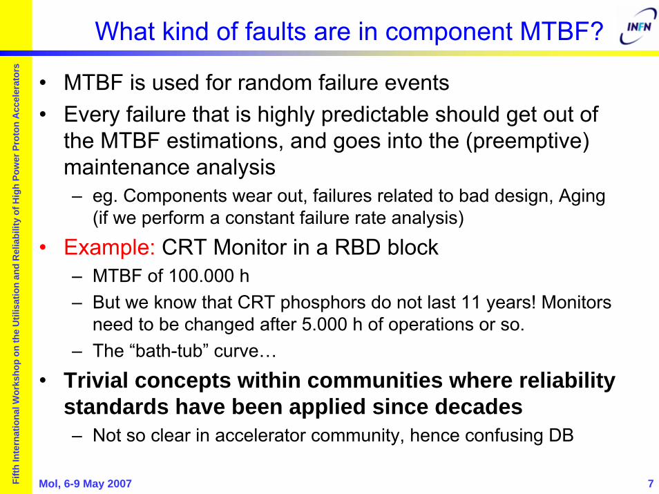
What kind of faults are in component MTBF?
• MTBF is used for random failure events• Every failure that is highly predictable should get out of
the MTBF estimations, and goes into the (preemptive) maintenance analysis– eg. Components wear out, failures related to bad design, Aging
(if we perform a constant failure rate analysis)
• Example: CRT Monitor in a RBD block– MTBF of 100.000 h– But we know that CRT phosphors do not last 11 years! Monitors
need to be changed after 5.000 h of operations or so.– The “bath-tub” curve…
• Trivial concepts within communities where reliability standards have been applied since decades– Not so clear in accelerator community, hence confusing DB

Mol, 6-9 May 2007 8Fifth
Inte
rnat
iona
l Wor
ksho
p on
the
Util
isat
ion
and
Rel
iabi
lity
of H
igh
Pow
er P
roto
n A
ccel
erat
ors
Design issues
• Often many “reliability” problems can be truly identified as component design issues (weak design) or improper operation (above rated values)
• e.g. very successful SNS operation– problems due to components providing
non critical functionalities but with failure modes with drastic consequences
Mol, 6-9 May 2007 9Fifth
Inte
rnat
iona
l Wor
ksho
p on
the
Util
isat
ion
and
Rel
iabi
lity
of H
igh
Pow
er P
roto
n A
ccel
erat
ors
Mol, 6-9 May 2007 10Fifth
Inte
rnat
iona
l Wor
ksho
p on
the
Util
isat
ion
and
Rel
iabi
lity
of H
igh
Pow
er P
roto
n A
ccel
erat
ors
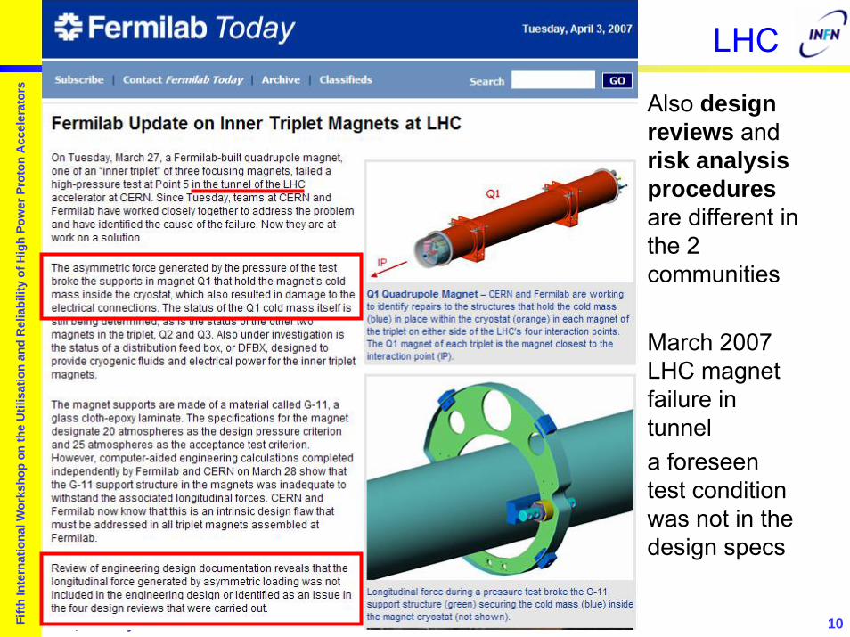
LHC
Also design reviews and risk analysis proceduresare different in the 2 communities
March 2007 LHC magnet failure in tunnela foreseen test condition was not in the design specs

Mol, 6-9 May 2007 11Fifth
Inte
rnat
iona
l Wor
ksho
p on
the
Util
isat
ion
and
Rel
iabi
lity
of H
igh
Pow
er P
roto
n A
ccel
erat
ors
But also cases of significant design effort
• LHC Machine Protection system– Energy stored in each of the 2 proton beams will be 360 MJ– If lost without control serious damage to hardware
• 1 kg of copper melts with 700 kJ– Analysis meant to trade off safety (probability of undetected
beam losses leading to machine damage) and availability (number of false beam trips per year induced by the system)
– Complete reliability modeling
• LHC magnetsQuench Protection System– Huge energy stored in
SC magnets (10 GJ)– Needs to be gracefully
handled

Mol, 6-9 May 2007 12Fifth
Inte
rnat
iona
l Wor
ksho
p on
the
Util
isat
ion
and
Rel
iabi
lity
of H
igh
Pow
er P
roto
n A
ccel
erat
ors
Lumped components database
• Reduce the accelerator complexity to a simple system• System composed of “lumped” components
– Various sources: IFMIF, SNS, APT estimates, internal eng. judg.– + a bit of optimism and realism
System Subsystem MTBF (h) MTTR (h)Injector Proton Source 1,000 2
RFQ 1,200 4
NC DTL 1,000 2
Support Systems Cryoplant 3,000 10
Cooling System 3,000 2
Control System 3,000 2
RF Unit High Voltage PS 30,000 4
Low Level RF 100,000 4
Transmitters 10,000 4
Amplifier 50,000 4
Power Components 100,000 12
Beam Delivery System Magnets 1,000,000 1
Power Supplies 100,000 1

Mol, 6-9 May 2007 13Fifth
Inte
rnat
iona
l Wor
ksho
p on
the
Util
isat
ion
and
Rel
iabi
lity
of H
igh
Pow
er P
roto
n A
ccel
erat
ors
MTBF data
• We cannot rely on MTBF data sources for typical accelerator components (usually special components)
• The set of data is used to develop a system scheme that guarantees the proper reliability characteristics with the given components by using– fault tolerance capabilities– redundancy patterns
• Experimental activities foreseen within EUROTRANS will provide more knowledge on some of the reliability characteristics of the key components
• Also SNS operational experience is very relevant

Mol, 6-9 May 2007 14Fifth
Inte
rnat
iona
l Wor
ksho
p on
the
Util
isat
ion
and
Rel
iabi
lity
of H
igh
Pow
er P
roto
n A
ccel
erat
ors
EUROTRANS linac
96 RF units 92 RF units

Mol, 6-9 May 2007 15Fifth
Inte
rnat
iona
l Wor
ksho
p on
the
Util
isat
ion
and
Rel
iabi
lity
of H
igh
Pow
er P
roto
n A
ccel
erat
ors
Parts count
• With a “parts count” estimate we come to an obviously short MTBF ~ 30 h
• Split into:– Injector: 7.7%– Spoke linac: 45.4%– High energy linac: 43.5%– Beam line: 0.6%– Support systems: 2.7%
• Of course, the highest number of components is in the linac (nearly 100 RF units each, with each RF units having an MTBF of 5700 h...
• That already suggests where to implement strategies for redundancy and fault tolerance implementation

Mol, 6-9 May 2007 16Fifth
Inte
rnat
iona
l Wor
ksho
p on
the
Util
isat
ion
and
Rel
iabi
lity
of H
igh
Pow
er P
roto
n A
ccel
erat
ors
SubsystemsInjector
Support Systems
RF Units
RF Unit MTBF (full) ~ 5700 hours
RF Unit MTBF (in-tunnel) ~ 6100 hours
Standard support systems, with MTBFs only moderately tailored to mission time. Each system R(Mission time) = 0.48.

Mol, 6-9 May 2007 17Fifth
Inte
rnat
iona
l Wor
ksho
p on
the
Util
isat
ion
and
Rel
iabi
lity
of H
igh
Pow
er P
roto
n A
ccel
erat
ors
Initial Scenario – All Series, no redundancy
• Worst possible case– similar to parts count
• All component failures lead to a system failure
• Poor MTBF• Too many failures
per mission
• Mostly due to RF units• 5700/188 = 30.32 h
System MTBF 31.2 hours
Number of failures 70.23
Steady State Availability 87.2 %

Mol, 6-9 May 2007 18Fifth
Inte
rnat
iona
l Wor
ksho
p on
the
Util
isat
ion
and
Rel
iabi
lity
of H
igh
Pow
er P
roto
n A
ccel
erat
ors
Mitigating occurrence of faults by system design
• Clearly, in the region where we are driven by high number of moderately reliable components we don’t want a series connection (where each component fault means a system fault)– Need to provide fault tolerance
• Luckily, the SC linac has ideal perspectives for introducing tolerance to RF faults:– highly modular pattern of repeated components providing the
same functions (beam acceleration and focussing)– individual cavity RF feed, digital LLRF regulation with setpoints
and tabulated procedures
• In the injector low fault rates can be achieved by redundancy

Mol, 6-9 May 2007 19Fifth
Inte
rnat
iona
l Wor
ksho
p on
the
Util
isat
ion
and
Rel
iabi
lity
of H
igh
Pow
er P
roto
n A
ccel
erat
ors
2 Sources -∞ Fault Tolerant SC section
System MTBF 796.91 hours
Number of failures 2.75
Steady State Availability 99.5 %
• Double the injector– Perfect switching– Repair can be
immediate• Assume infinite FT
in linac section• Reliability goal is
reached!
Dream LinacDream Linac

Mol, 6-9 May 2007 20Fifth
Inte
rnat
iona
l Wor
ksho
p on
the
Util
isat
ion
and
Rel
iabi
lity
of H
igh
Pow
er P
roto
n A
ccel
erat
ors
2 Sources – Redundant RF Systems
System MTBF 757.84 hours
Number of failures 2.89
Steady State Availability 99.5 %
• Keep 2 sources• Assume that we can
deal at any moment with any 2 RF Units failing at any position in the SC sections– Maintenance can be
performed on the failing units while system is in operation
– ideal detection and switching
• Still within goals

Mol, 6-9 May 2007 21Fifth
Inte
rnat
iona
l Wor
ksho
p on
the
Util
isat
ion
and
Rel
iabi
lity
of H
igh
Pow
er P
roto
n A
ccel
erat
ors
Realistic RF Unit correction provisions
• When assuming parallelism and lumped components we should be consistent in defining repair provisions
• For example, the components in the RF system that are out of the main accelerator tunnel can be immediately repairable, but certainly not all RF power components that are inside the protected-access tunnel– Even if the in-tunnel component can be considered in parallel
(we may tolerate failures to some degree), all repairs are executed ONLY when the system is stopped
– This greatly changes system MTBF
Mol, 6-9 May 2007 22Fifth
Inte
rnat
iona
l Wor
ksho
p on
the
Util
isat
ion
and
Rel
iabi
lity
of H
igh
Pow
er P
roto
n A
ccel
erat
ors
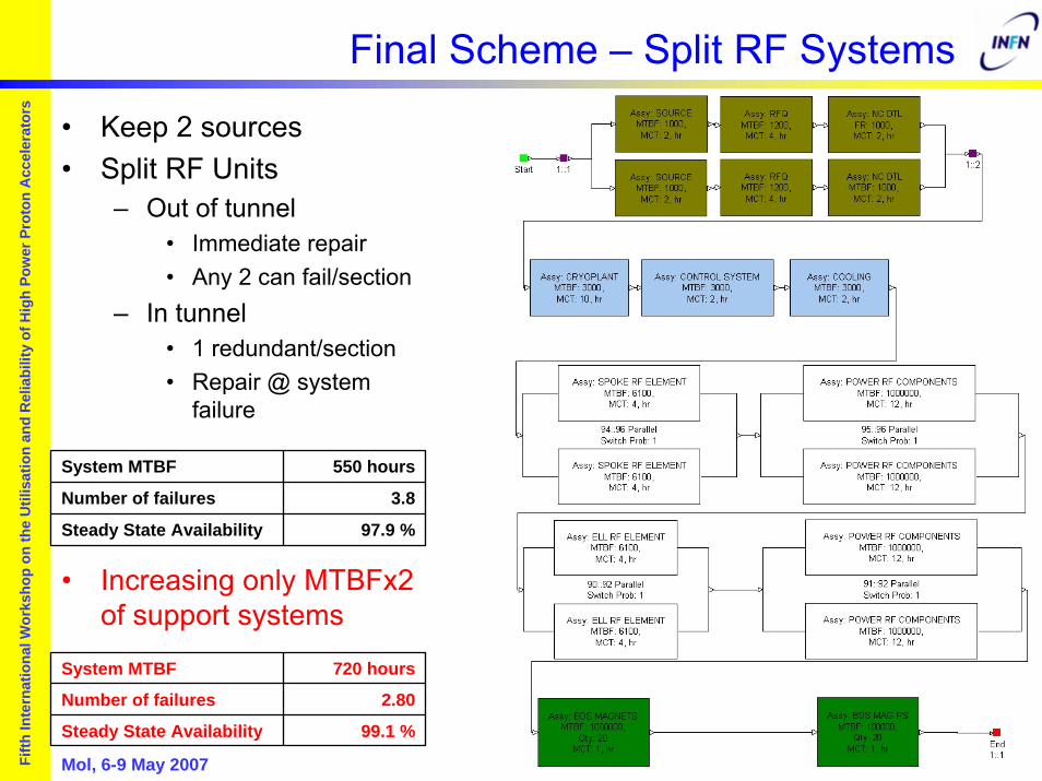
Final Scheme – Split RF Systems
System MTBF 550 hours
Number of failures 3.8
Steady State Availability 97.9 %
System MTBF 720 hours
Number of failures 2.80
Steady State Availability 99.1 %
• Keep 2 sources• Split RF Units
– Out of tunnel• Immediate repair• Any 2 can fail/section
– In tunnel• 1 redundant/section• Repair @ system
failure
• Increasing only MTBFx2 of support systems

Mol, 6-9 May 2007 23Fifth
Inte
rnat
iona
l Wor
ksho
p on
the
Util
isat
ion
and
Rel
iabi
lity
of H
igh
Pow
er P
roto
n A
ccel
erat
ors
System MTBF “evolution”
# Inj. Fault Tolerance degree RF unit repair System MTBF
1 None, all in series At system stop 31
2 Infinite Immediate 797
2 94/96 in spoke, 90/92 in ell are needed Immediate 758
2 94/96 in spoke, 90/92 in ell are needed, more realistic correction provisions, by splitting the RF system
• Immediate for out of tunnel
• at system stop for in tunnel
558
2 94/96 in spoke, 90/92 in ell are needed, split RFSUPPORT SYSTEM MTBF * 2
• Immediate for out of tunnel
• at system stop for in tunnel
720
2 94/96 in spoke, 90/92 in ell are needed, split RFIN-TUNNEL MTBF * 10
• Immediate for out of tunnel
• at system stop for in tunnel
760
Mol, 6-9 May 2007 24Fifth
Inte
rnat
iona
l Wor
ksho
p on
the
Util
isat
ion
and
Rel
iabi
lity
of H
igh
Pow
er P
roto
n A
ccel
erat
ors
Lesson learned
• Type of connection & corrective maintenance provisions change dramatically the resulting system reliability, independently of the component reliability characteristics
• This analysis allows to identify choices of components for which we need to guarantee high MTBF, due to their criticality or impossibility of performing maintenance– in-tunnel components/more robust support systems
• Analysis here is still crude, while similar MTBF values are reported in literature, the MTTR are inserted mainly for demonstration purposes– several issues ignored: decay times before repair, logistic
issues, long times if cooldown/warmup is needed...
Mol, 6-9 May 2007 25Fifth
Inte
rnat
iona
l Wor
ksho
p on
the
Util
isat
ion
and
Rel
iabi
lity
of H
igh
Pow
er P
roto
n A
ccel
erat
ors
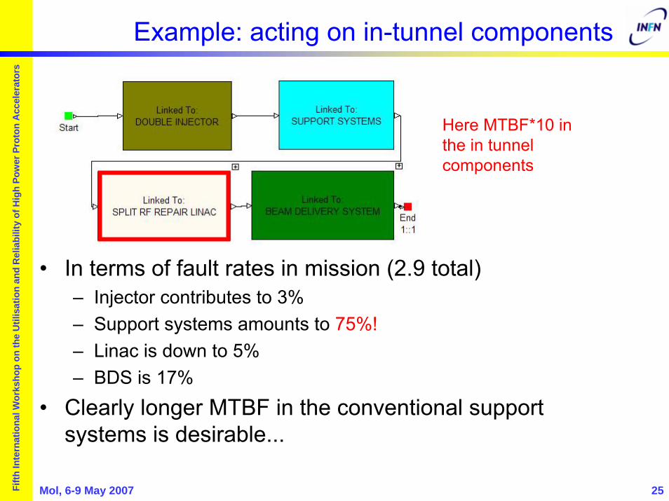
Example: acting on in-tunnel components
• In terms of fault rates in mission (2.9 total)– Injector contributes to 3%– Support systems amounts to 75%!– Linac is down to 5%– BDS is 17%
• Clearly longer MTBF in the conventional support systems is desirable...
Here MTBF*10 in the in tunnel components

Mol, 6-9 May 2007 26Fifth
Inte
rnat
iona
l Wor
ksho
p on
the
Util
isat
ion
and
Rel
iabi
lity
of H
igh
Pow
er P
roto
n A
ccel
erat
ors
Example: acting on support systems
• In terms of fault rates in mission (2.8 total)– Injector contributes to 3%– Support systems amounts to 35%– Linac is 45%– BDS is 16%
• More balanced share of fault areas• MTBF increase only in conventional support facilities
Here MTBF*2 in the support systems
Mol, 6-9 May 2007 27Fifth
Inte
rnat
iona
l Wor
ksho
p on
the
Util
isat
ion
and
Rel
iabi
lity
of H
igh
Pow
er P
roto
n A
ccel
erat
ors
Fault tolerance
• Still, analysis assumes a high degree of fault tolerance, where the failure of an RF unit is automatically recovered without inducing beam trips on target in timescales ~ 1 s– challenging technical issue in LLRF and beam control systems
• Two tasks of the EUROTRANS accelerator program (Tasks 1.3.4 and 1.3.5) are dedicated to reliability analysis and LLRF issues for providing fault tolerance in the high power linac

Mol, 6-9 May 2007 28Fifth
Inte
rnat
iona
l Wor
ksho
p on
the
Util
isat
ion
and
Rel
iabi
lity
of H
igh
Pow
er P
roto
n A
ccel
erat
ors
Conclusions
• Even in the absence of a validated reliability database for accelerator components the standard reliability analysis procedures indicate where design effort should be concentrated:– providing large degree of fault tolerance whenever possible
• Meaning: fault detection, isolation and correction procedures– providing additional design effort aimed at longer MTBF only in
critical components
• Study here is an illustration of how, with minimal “tweaking” of the component MTBF, a simple model for an accelerator system can be altered (adding redundancy and fault tolerance capabilities) in order to meet the ADS goals