reliability studies of integrated modular engine system ... · reliability studies of integrated...
TRANSCRIPT
NASA Technical Mern_orandum 106178 __
AIAA-93-1886 ....
/te-
-- . 2_
Reliability Studies of Integrated Modular
Engine System Designs
Terry L. Hardy
National Aeronautics and Space Administration
Lewis Research Center ....
Cleveland, Ohio
= =
and
Douglas C. Rapp
Sverdrup Technology, Inc.
Lewis Research Center Group
Cleveland, Ohio
Prepared for the
29th Joint Propulsion Conference and Exhibit
cosponsored by the AIAA, SAE, ASME, and ASEE
Monterey, California, June 28-30, 1993
IW A
(NASA-TM-106178) RELIABILITY
STUDIES OF INTEGRATED MODULAR
ENGINE SYSTEM DESIGNS (NASA) 19 p
N93-27022
Unclas
G3/20 0164789
https://ntrs.nasa.gov/search.jsp?R=19930017833 2018-07-10T13:16:42+00:00Z

i
RELIABILITY STUDIES OF INTEGRATED MODULAR ENGINE SYSTEM DESIGNS
Terry L. HardyNational Aeronautics and Space Administration
Lewis Research Center
Cleveland, Ohio 44135
and
Douglas C. RappSverdrup Technology, Inc.
Lewis Research Center GroupBrook Park, Ohio 44142
Abs_act
A study was performed to evaluate the reliabil-
ity of Integrated Modular Engine (IME) concepts. Com-
parisons were made between networked IME systems
and non-networked discrete systems using expander
cycle configurations. Both redundant and nonredundant
systems were analyzed. Binomial approximation andMarkov analysis techniques were employed to evaluate
total system reliability. In addition, Failure Modes and
Effects Analyses (FMEA), Preliminary Hazard Analy-
ses (PHA), and Fault Tree Analysis (FTA) were per-
formed to allow detailed evaluation of the IME concept.
A discussion of these system reliability concepts is alsopresented.
Introduction
Integrated Modular Engine (IME) designs are
currently being considered for use in various space pro-pulsion applications) 4 Conventional nonnetworked, or
discrete, engines are designed such that each engine sys-
tem is a standalone unit. In the discrete system, if a tur-
bopump fails the corresponding thrust chamber must
also be shut down. In the networked, or modular, engine
concept, however, all turbopump assemblies and thrust
chamber assemblies are joined by common manifolds.
In this system, therefore, a turbopump or thrust chambercould be shut down independently should a failure occur
in either component. Therefore, the IME offers poten-
tial advantages of increased fault tolerance and reliabil-
ity when compared to discrete systems. The purpose of
this report is to evaluate and compare the reliability ofthe IME and the discrete engine systems, to determine
the reliability drivers of the IME, and to conduct a sensi-
tivity study of the effects of component failures on sys-
tem reliability of the IME.
Both quantitative and qualitative techniques
were used to evaluate the IME reliability. The quantita-
tive analyses consisted of binomial and Markov analy-
ses. A binomial approximation technique was employed
to characterize the reliability of the system based on
component shutdown probabilities. Markov techniques
were also used to evaluate the effects of engine burn
duration on system reliability based on component fail-
ure rates. Because of the large uncertainty in the avail-
able component reliability data, the emphasis of the
binomial approximation and Markov analyses was to
conduct relative comparisons between modular and dis-
crete systems, rather than to obtain absolute failure data.
The qualitative techniques included Failure Modes and
Effects Analyses (FMEA), Preliminary Hazard Analy-
ses (PHA), and Fault Tree Analyses (FTA). An FMEAwas conducted for the IME to determine the effects of
single-point failures on the system. A PHA was used to
identify potential hazards associated with the operation
of the IME. Finally, an FTA was prepared to assist in the
characterization of system-wide failures.
System Description
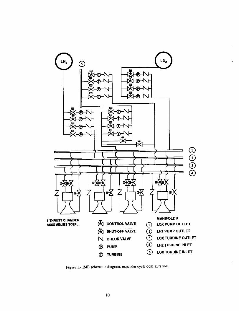
An Integrated Modular Engine system sche-
matic is provided in Fig. 1. This design is based on aNASA Lewis Research Center effort to examine the
IME concept and to determine methods of physicallyassembling such a system _. In this IME design an
expander cycle configuration was used. As a baseline,
eight thrust chamber assemblies are connected with four
fuel and four oxygen turbopump assemblies. Five mani-folds are required in this design to connect the thrust
chambers and the turbopumps. Shutoff valves are used
to isolate the pumps, turbines, and the thrust chambers
in the event of a degradation of any of these compo-
nents. The required number of valves for the IME is 66,with 4 valves for each thrust chamber, fuel turbopump
and oxidizer turbopump, plus 2 turbine bypass valves.
Details of this IME design are provided in reference 5.
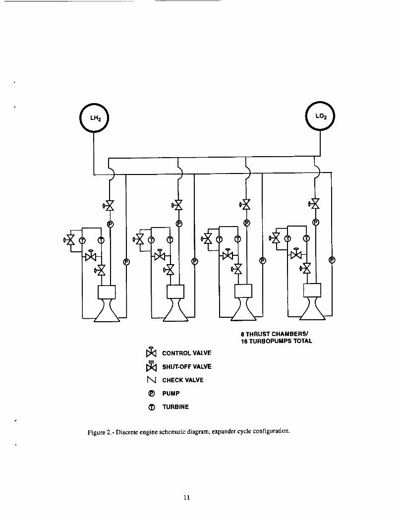
By comparison, a discrete system, shown in Fig. 2, has
no manifolds and 4 valves for each engine for a total of32 valves.
Analysis Techniques and Results
Several quantitative and qualitative techniques
wereused to evaluate the reliability of the IME, includ-
ing binomial approximation, Markov analysis, FMEA,
PHA, and fault trees. A description of each process is
included, and results for the above system configuration
are provided for each of the techniques.
Binomial Approximation
In the binomial approximation technique, also
known as the k-out-of-N modeling technique, it is
assumed that k components out of a total of N compo-
nents must operate for the entire system to perform suc-
cessfully. Therefore, the technique applies only to cases
where redundancy is used. The following equation is
used in the binomial approximation analysis of redun-
dant systems: 6
N-I
X NI Re z ( 1 - Re) N- xReTatal _" ReN+ x[ (N-x)[x=k
where:
ReTota t = total system reliability (1.0 - PrToua)
Re = component reliability (1.0 - Pr)
PrTota i = total system shutdown probability
Pr = component shutdown probability
k -- minimum number of componentsrequired for system operation
N = total number of components
To analyze the IME system with redundancy,
the reliability of each subsystem (fuel pump, oxidizer
pump, fuel turbine, oxidizer turbine, thrust chamber)
was obtained by multiplying the reliabilities of the com-
ponents in each redundant subsystem (components in
series). The total subsystem reliability was then
obtained by using the binomial equation for the parallel
subsystems. For instance, for the fuel turbopumps, k = 3
and N=4 for the baseline case. The total system reliabil-
ity was then obtained by multiplying the total subsystem
reliabilities. For the discrete system the reliability of
each engine was obtained by multiplying the reliabilities
of each component. The binomial approximation was
then used to obtain total system reliability (k = 7, N= 8
for the baseline case) for the parallel engine systems.
For the cases without redundancy, the part reli-
abilities can be multiplied to obtain a total system reli-
ability, ReToua. The total system failure probability is
calculated in either case as 1.0-PrToml.
Tables I and II provide lists of components andtheir estimated failure rates for the IME and discrete
systems, respectively. The failure rate is defined as the
number of failures per 1000 firings (fir) for the binomial
analysis. With the exception of the manifold estimates,these failure rates were obtained from reference 4,
where the Pratt & Whitney Rocket Engine ReliabilityDatabase was used. This database takes into account
historical engine failures based on flight data. Because
of the limited amount of data available, a high degree of
uncertainty associated with the failure rates can be
expected. However, the use of the data does allow for
relative comparisons between IME and discrete systems.The manifold failure rates are based on information
from hydrogen and oxygen ducting. Again, a high
degree of uncertainty is associated with these manifold
failure rates. A sensitivity analysis was performed on thevalve and manifold shutdown rates to determine the
effects of these parameters on overall system reliabil-
ity. Several key assumptions were used to formulate the
analysis using the binomial distribution:
1. No partial failures are allowed; the only condi-
tions are success and failure. The components
are not repairable.
2. Only active redundancy is considered (i.e.. all
components are operating prior to the failure ofany component).
3. No operating range concerns were included in
the analysis (i.e., if one IME turbopump fails, it
is assumed that the remaining turbopumps can
meet the power requirement with no change in
their reliability). Therefore, the failure rates
were constant and independent of the number of
components functioning.
4. The health monitoring system can identify and
respond to a problem 100 percent of the time.
5. No common cause failures were included.
6. Sensor and controller reliabilities were not
included in the analysis.
7. If a turbine (pump) failed on either the oxygen
or hydrogen circuit the corresponding pump
(turbine) would be deactivated,
8. Loss of a turbine bypass valve will lead to IME
system loss (bypass simultaneously affects allturbines and adverse effects cannot be miti-
gated).
The binomial analysis was performed over a
range of 2 to 12 thrusters. For the IME the number of
turbopump assemblies was half the number of thrustchamber assemblies in each case. In addition, in the
cases without redundancy the IME design did notinclude the isolation and check valves for the turboma-
chinery or for the nozzle coolant channel. These isola-
tion and check valves would only be required for
component isolation after failure; in the case without
redundancy any component failure will cause total sys-
tem failure and isolation would not be not necessary.
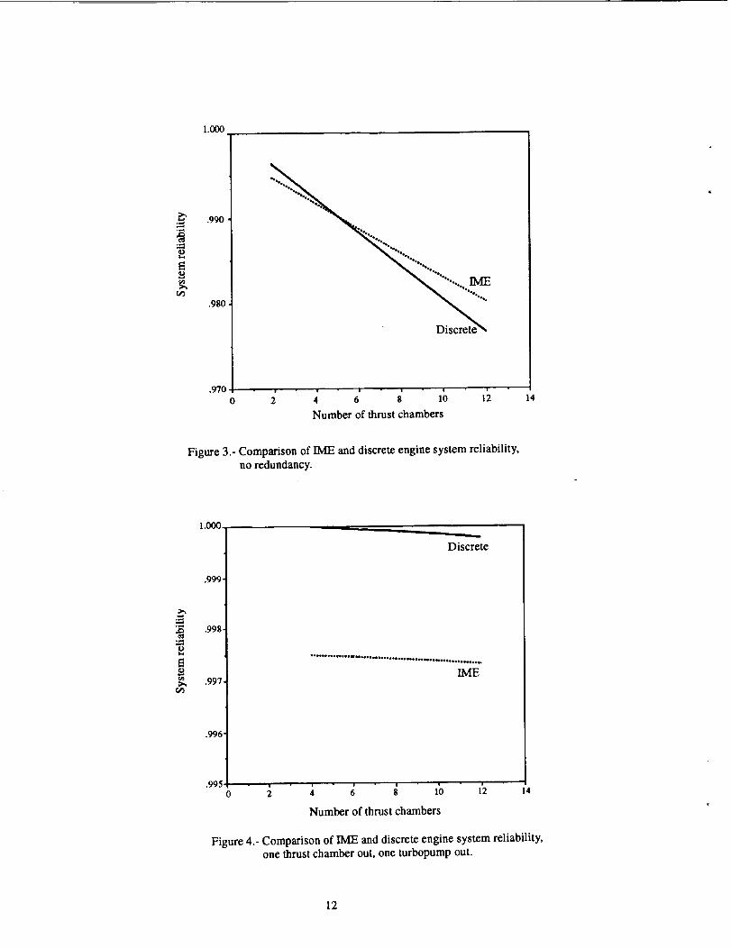
The results of the binomial approximation
analysis are shown in Figs. 3 to 6. Figure 3 compares the
reliability of the IME with that of the discrete system for
systems with 2 to 12 thrust chambers and where no
redundancy is available (i.e., all components must oper-
ate). From the figure it can be seen that the discrete sys-
tems showed higher reliabilities than the IME systemsfor cases with less than six thrust chambers. For six
thrust chambers and higher the IME proved to be more
reliable than the discrete system. At low numbers of
thrust chambers the manifold failure probability causes
the IME system reliability to be reduced in comparison
to the discrete system. As the number of thrust chambers
is increased, the turbomachinery becomes a more
important factor in the total system reliability. Because
the IME has fewer turbopumps than the discrete system,
the IME becomes more reliable than the discrete system
as the number of thrust chambers and turbopump assem-blies is increased.
Figure 4 shows a similar comparison assuming
that the system has redundancy and can operate with one
thrust chamber and one turbopump shutdown. In the
case of the [ME, this means that one turbopump and one
thrust chamber could be shut down and the IME system
would still meet the system thrust requirement; in the
discrete system, if either a thrust chamber or turbopump
was shutdown, one entire engine system could be shut
down and the system would still meet the thrust require-
ment. It is apparent from a comparison of Figs. 3 and 4
that redundancy provides a significant benefit for both
systems. Redundancy increases reliability by routing
component failure to other operating components. As
can be seen by Fig. 4, the discrete system showed higher
system reliabilities when compared to the IME. The dis-
crete system showed reliabilities between 0.99998 and0.99975 for 4 to 12 thrusters. These reliabilities corre-
sponded to total system failure rates of 0.02 to 0.25 per
1000 firings. In contrast, the IME had reliabilities whichvaried from 0.99789 to 0.99773, or failure rates of 2.11
to 2.27 per 1000 firings. Therefore, the system failure
rates for the IME were approximately one order of mag-
nitude higher than the discrete system.
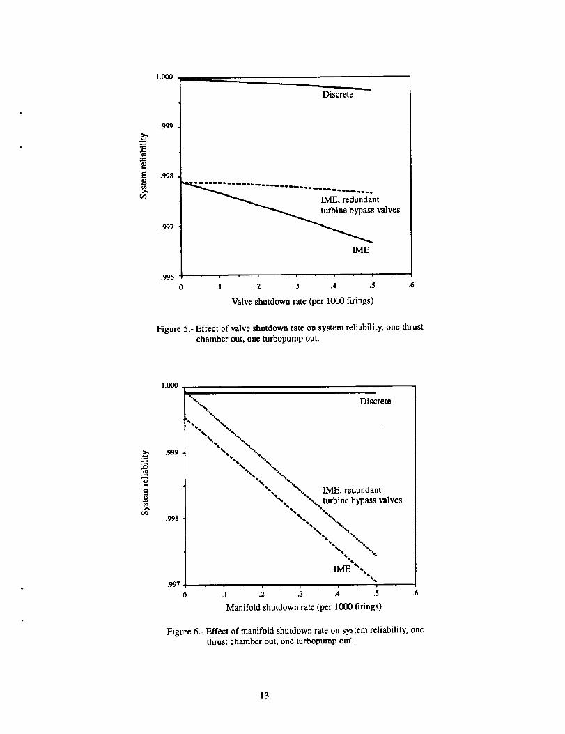
From preliminary reliability studies not
included in this report it appears that the reliability driv-
ers are the valves and the manifolds, specifically
because the turbine bypass valves and the manifolds
represent the potential for single point failures. There-
fore, sensitivity studies were performed on the reliabili-
ties associated with these components. Figure 5 shows
the effect of valve shutdown rate on system reliability
for both the discrete and IME systems with eight thrust
chamber assemblies. The valve failure rate (shutdown
rate) was varied from 0 to 0.5 per 1000 firings. From the
figure it can be seen that, even if the valves had a shut-
down rate of 0 (100 percent reliability), the IME showed
lower reliabilities than the discrete system. Because the
turbine bypass valve represents a single point failure
under the assumptions given previously, the analysis
was also performed allowing redundancy in the bypass
valves. Again, the discrete system showed higher reli-abilities than the IME, but the reliability of both the dis-
crete and IME systems did improve with the addition of
redundancy. It should be noted that, because of the
uncertainty tn whether the loss of turbine bypass valves
cause system failure, further analyses are required to
determine the dependence of the system on these valves.
However, this figure illustrates that, although the valve
failure rate can affect the total system reliability, the
valves do not appear to be the reason for reduced IME
reliability in comparison to the discrete engine system.
Figure 6 shows the effect of manifold failure
rate on total system reliability. From the figure it can beseen that the discrete engine concept provides higher
reliabilities when compared to the IME concept except
when manifold reliability was high and the turbine
bypass valves were assumed to be redundant. The dis-
crete system showed no change because no manifolds
were assumed in this system. Examination of the design
in Fig. 1 shows that the manifolds represent a single
point failure, where loss of a manifold results in loss of
the system. The manifolds would include the connec-
tions from the component piping (flanges, fasteners,
etc.) as well as the ducting itself. Therefore, because the
manifold has been shown to be the key reliability driver,it may be necessary to focus future efforts in IME design
on manifold reliability, including connections, for the
IME concept to achieve reliabilities similar to that of the
discrete system.
The results of the binomial analysis show the
significant improvement in system reliability derived
from redundancy. Discrete systems increase reliability
by isolating failures to the singular unit and reducing
dependence on shared components, such as manifolds.
Therefore, based on this analysis, the real reliability
issue is not redundancy but the actual system design.
Markov analysis techniques are useful tools inthe reliability modeling of stochastic systems. 6'7 To this
end, a time-homogeneous Markov process with finite
state space was used to compare the time-dependent
reliability of IME and discrete engine system designs.
Recording the degradation of system reliability with
time proves useful in defining system operation enve-
lopes based on demanded reliability and component fail-
ure rates. Furthermore, system reliability can be defined
based on component integration and, to some extent,
mutual component interaction for common cause analy-
sis. The reliability results of IME and discrete engine
system design concepts are presented subsequently. The
initial discussion focuses on briefly introducing the
Markov technique and assumptions employed. As in the
binomial analysis, emphasis is centered on system sensi-
tivity to component failure rates and not on the absolute
magnitude of these rates.
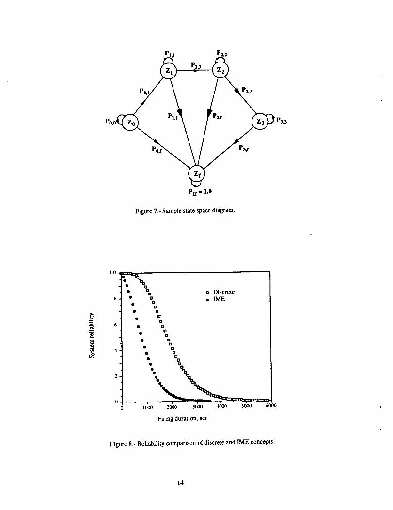
The time-homogeneous Marker analysis tech-
nique determines a system's reliability over time based
on the system's present operational condition (state). A
state is defined as a given combination of failed and
healthy components. A system state space comprises all
states in which the system can occupy: an assumed ini-
tial no-failure state (Zo), single or multiple failed com-
ponent state (Z i) and a final system failed state (Zf). Asimple Marker state space is diagrammed in Fig. 7. The
system progresses in time from state Z o, at time t=0, toother states within the finite state space. The transition
probability, Pi,j, characterizes the likelihood of the sys-tem transitioning from any current state Zi to a new
state, Z/, in which a single system component has failedduring discrete time interval _St.System state transition
probability is directly proportional to the componentfailure rates and, in general, is only dependent on 5t
(time-homogeneous).
The results of this type of analysis are insight-
ful. As time progresses during system operation, the
probability of system failure is determined by the rate atwhich its individual components fail and how their fail-
ure will impact the system. Increases in system failure
probability during each successive time interval estab-
lishes a failure probability distribution. This probability
distribution documents the temporal increase in system
failure probability, and its difference from unity at each
time step defines the system reliability Resys. Similarly,
the mean time to failure (MT1Ts) (i.e., the expected
time to system failure) may be determined from the dis-tribution.
Unless noted otherwise, component failurerates were from reference 4 and are listed in Tables I and
II. The components considered in these Markov analy-
ses were the liquid oxygen turbopumps, liquid hydrogen
turbopumps, thrust chamber assemblies and the mani-
folds, and turbine bypass valves. Each component fail-
ure rate is a composite of the failure rates of
subassemblies that are considered to comprise the com-
ponent. Thus, if any one component subassembly fails,
the component itself failed.
Finally, some assumptions invoked in thisMarker analysis follow:
1. All components are nonrepairable, actively
redundant, load sharing, and, upon failure, fail
completely (no partial failures). Load sharing
implies that component failure rates are propor-
tional to the load carried by the component.
2. For the l/viE design, the manifolds and turbine
bypass valves were represented as single pointfailures.
3. When an l/VIE thrust chamber assembly fails, the
thrust chamber assembly 180 ° from the failed
one is immediately shut down in order to main-
tain thrust balance. Hence, failing one thrust
chamber assembly results in a net loss of two
during a state transition.
4. System failure was assumed to occur when the
system can no longer provide 100 percent
thrust. IME system failure was defined as
greater than one failed liquid oxygen tur-
bopump assembly, greater than one failed liquid
hydrogen turbopump assembly, greater thanfour shutdown thrust chamber assemblies (i.e.,
greater than two failed overall), and instanta-
neous failure with the single-point failures. Dis-
crete system failure was defined as greater than
four failed engines.
Figure 8 graphs the temporal decay of reliabil-
ity of IME and discrete systems. At all system firing
times, the discrete engine system had higher reliability
than the IME system. The IME system demonstrated a899-second M'ITF s in comparison to the discrete system
with a 1964-second M'ITF s. The reduced mean time tosystem failure of the IME was the result of, in part, sys-
tem sensitivity of single point failures (manifolds, tur-
bine bypass valves) and, in part, the intrinsically higher
dependence of system operation on a smaller number of
components. Likewise, at a demanded 99 percent reli-
ability level, the discrete system could operate for 470seconds longer than the IME system, from 500 seconds
(discrete) to 30 seconds (IME). The capability of calcu-
lating acceptable firing durations based on component
failure rates and demanded system reliability demon-
strates the merit of the Marker analysis technique.
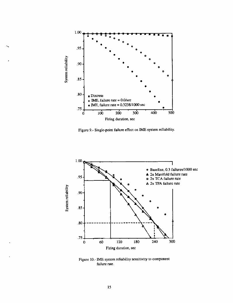
The IME system was found to be vulnerable to
single point failures by the binomial analysis. Hence, the
effect of assumed single point failure probability on
IME system reliability was investigated by assumingfailure-free (100 percent reliability) manifolds and tur-
bine bypass valves (TBPVs) using Markov. System reli-
ability improved as shown in Fig. 9. A dramatic
improvement of 377 percent was achieved in firing
duration (30 to 143 seconds) at 99 percent reliability
when manifold/TBPV reliability is set to 1.0. Improve-ments in system firing time tapered off at lower reliabil-
ity levels, indicating a decreasing importance of single-
4
point failures with time. This point is expanded further
subsequently. Note that these increases in fu'ing dura-
tion, however large, were still less than the predicted fir-ing durations of the discrete systems at all reliabilitylevels.
Clearly, total system reliability is dependent on
each component's failure rate. When a system's sensitiv-
ity to these rates is established, critical components that
dictate system reliability are identified for reliabilityenhancement. A constant failure rate (0.0003 failures/
second) was imposed on all system components as a
baseline. Each component's failure rate was then sys-
tematically doubled, and the resulting system reliabilitywas compared with the baseline case.
With the noted exception of the manifolds/
TBPVs at a reliability level greater than 94 percent forthe IME system, the turbopumps were the most critical
components in determining reliability for all systems(discrete, IME). Figure 10 illustrates the reliability curvecrossover of the manifold/TBPV with both the tur-
bopumps and thrust chambers for the IME system. This
crossover was due to both a faster rise and larger spread
in the distribution of system failure probability due to
doubling the manifold/'rBPV failure rate. Also, the fail-
ure of thrust chamber assemblies was more significant
for a discrete system than an IME system at the 99 per-
cent reliability level. Firing durations decreased by 25percent (247 to 186 seconds) in comparison to 3 percent
(31 to 30 seconds) for the IME system. The results con-
firm the obvious fact that increasing component failure
rates decrease system reliability.
Finally, the health monitoring system for all
these analyses was assumed to instantly respond 100
percent of the time to component failure by shutting off
and isolating the failed component. However, if an 80
percent effective health monitoring system assumptionis used, then 20 percent of all component failures go
undetected. Invoking this assumption, the reliability of
the redundant IME system is instantaneously dimin-
ished, at each second, by 20 percent of the failures expe-
rienced by a nonredundant system (ref. 4). This assumes
that allowing the failed component to operate does not
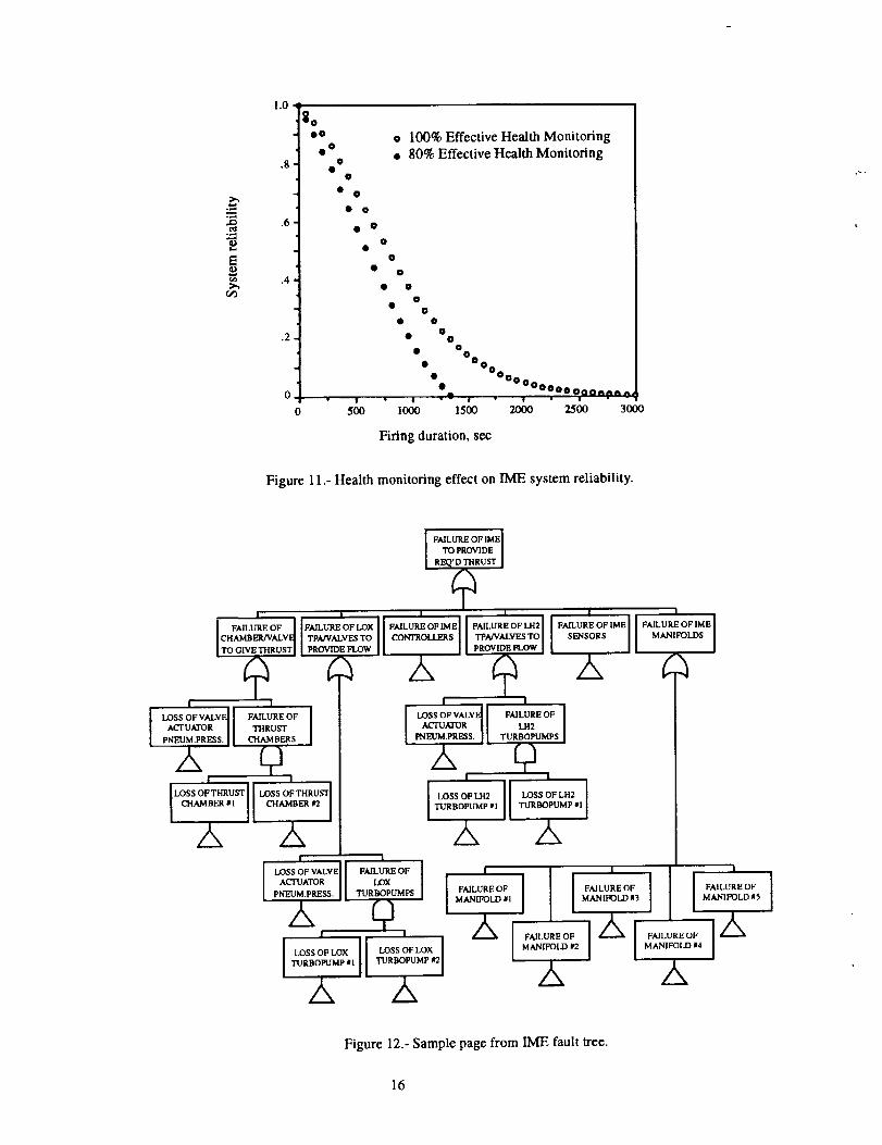
cause catastrophic system failure. Figure 11 demon-
strates an 80 percent reliable health monitoring system
degrading reliability of the IME system. For example,
system reliability decreased approximately 13 percent
for a 500-second firing duration. This reliability decline
increases with increasing firing duration until the system
fails with 100 percent probability at approximately 1300seconds.
Failure Modes and Effects Analysis
A Failure Modes and Effects Analysis (FMEA)
is an inductive technique which provides a method for
systematically identifying which parts can fail, how theyfail, and what are the effects of the failures. Once the
FMEA is completed, a Critical Items List (CIL) is pre-
pared; the CIL provides a summary of the items which
represent single point failures to the system. Generally,
the FIVlEA is used as a qualitative approach, although
the method can be used quantitatively by assigning fail-
ure probabilities for critical items and summing the indi-
vidual probabilities. The advantages of using an FMEA
analysis are that single point failures can be identified,
and hazards can be identified on a piecepart level. The
disadvantages of the FMEA lie in that, because the con-centration is on individual failures of components, com-
bined effects of coexisting failures (common causefailures) are not considered.
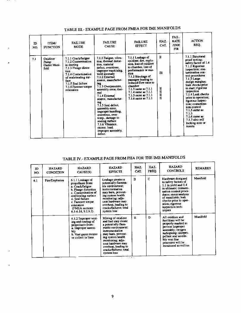
An FMEA was performed on the IME to iden-
tify component failure modes and their effects on the
IME. Table III shows an example from this FMEA for
the Oxidizer Pump Outlet Manifold, which includes the
ducting and the connections tO the manifold. Failure
modes on manifolds include crack/fatigue failures, con-
tamination in ducting and seals or sealing surfaces, seal
failure, and fastener torque relaxation. Previous studies 8
showed that leakage through flanges from fastener
torque relaxation could present major problems in flight
systems. Methods of mitigating this failure mode
require investigation for the I/vIE because of the largenumber of bolted flanges in this system. One option
could be to incorporate all-welded connections to
remove these failure modes; however, this design modi-
fication would reduce the ability to change out compo-
nents prior to flight, thus reducing the flexibility of the
IME. The CIL showed that the ignitor power supply fail-
ure, manifold failure, and valve actuator failure could be
single point failures in the IME design.
Preliminary. Hazard Analysis
A Preliminary Hazard Analysis (PHA) is a
qualitative inductive method used to assess the potential
hazards posed by the system. The PHA is usually pre-
pared in conjunction with the FMEA. The objectives of
the PHA are to identify the potential hazards within a
system and to determine the significance of the potential
accidents that might result from those hazards. Once
identified, control measures are developed for each ofthe hazards. These hazard reduction control measures
are, in the preferred order of application, as follows:
1. Design change
2. Engineered safety devices (e.g., redundant backups,
relief valves, etc.)
3. Safety devices (e.g., guards, shields, personnel pro-
tection devices, etc.)
4. Warning devices (e.g., alarms, lights, etc.)
5. Procedures and training
A PHA allows the qualitative identification of
both the probability and severity of the risks in the sys-
tem. Hazard probability and severity values are defined
in reference 9. However, the technique does not allow
for identifying common cause failures and does not han-
dle complex interactions in the system.
Table IV shows an example page from the PHA
developed for the IME. The hazard considered here is
fire or explosion in a manifold from leakage of propel-lants or from improper venting and routing of propel-
lants. Control procedures include hardware safety
factors, contamination control procedures, and leak
checks prior to operation. Projectiles also were found to
present a hazard to the manifold. Impact may causecracking or a surface anomaly leading to a failure and
the potential for loss of chambers or turbopumps. Con-
trol procedures for projectiles are similar to those
described for the fire/explosion hazard.
A Fault Tree Analysis (FTA) is a deductive
failure analysis technique which identifies one top event
and provides a method for determining the causes of that
event. 1o This approach differs significantly from those
discussed previously in that the analyst postulates that
the system has failed in some way and then attempts to
determine all credible ways in which the undesired
event can occur. The fault tree is a graphical model of
the sequences of faults and failures that lead to the
undesired event. Therefore, the fault tree represents the
logical relationship between some basic events and the
top event. The fault tree is a qualitative model of theevents leading to failure which can be evaluated quanti-
tatively. The quantitative evaluation of fault trees forms
one of the core techniques in the probabilistic riskassessment (PRA) of nuclear power plants.11-13
Fault trees are especially attractive for large,
complex systems such as the Integrated Modular Engine
because of the following:
1. The pictorial display of the system provides
insights into the failure consequence chains.
2. The relative effects of contributing factors to
failure of the system can be identified quantita-
tively,
3. The weak points in the system can be quantita-
tively identified.
4. The vulnerability of the system to common
cause failures can be readily identified.
Limitations to using a fault tree are that theanalyst may not include all failure possibilities (errors of
exclusion), there may be large uncertainty in the failure
rate data, and the process can be extremely time-con-
suming. However, probabilistic techniques, including
fault tree analyses, have been useful in assessing risk inmany NASA applications. 14
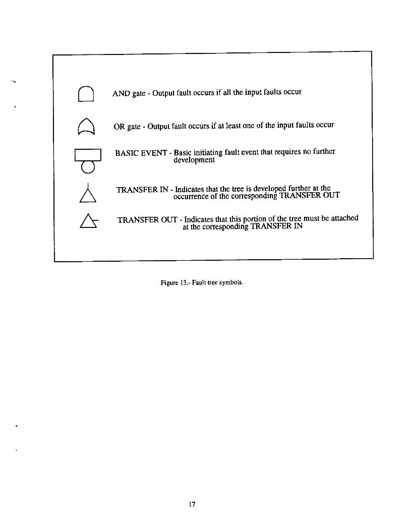
Figure 12 shows a sample page from the IME
fault tree, The fault tree was prepared at NASA Lewis
Research Center using the IRRAS code. IRRAS is a
model developed for the U.S. Nuclear Regulatory Com-
mission for the performance of probabilistic risk assess-ments. 15 (The symbols used in the figure are defined in
Fig. 13.) This fault tree did not include the failure of the
turbine bypass valves due to the uncertainty associated
with the system dependence on these components. From
the figure the top level event is "Failure of IME to pro-
vide required thrust;" this event can occur if any of thesecond level events occur. Note that, if the "Failure of
LH2 TPA/valves to provide flow" gate is examined, this
second level event can occur if the turbopumps are lost
or if the valve actuator pneumatic pressure is lost,assuming all the fuel turbopump valves operate using
the same pneumatic pressure. According to the faulttree, then, common cause failure could occur such that
all the valves are lost as a result of the pneumatic pres-
sure loss. This illustrates the strength of the fault tree
approach, the identification of common cause failures
such as valve actuator failure identified in this analysis.The VIA also showed that a circuit malfunction in the
ignitor power supply could represent a common cause
failure if the ignitors of all the thrust chambers operate
off the same power supply. It appears from an examina-
tion of the fault tree that the l/viE may be more suscepti-
ble to common cause failures than discrete systems.
In the nuclear industry, both reactor operating
experience and PRA results consistently indicate that
these common cause failures are major contributors toaccidents. 12 Reference 16 states that propulsion systems
are inherently vulnerable to correlated (common cause)failures due to their high energy. Therefore, further
efforts using quantitative probabilistic risk assessment
techniques are required to determine the impact of com-mon cause on the IME.
A study was conducted to evaluate the reliabil-
ity of IME concepts. The reliability of the IME was
compared to that of discrete engines using an expandercycle configuration. Binomial approximation techniques
and Markov analyses were conducted to form this com-
parison. In addition, a Failure Modes and Effects Analy-
sis, a Preliminary Hazard Analysis, and a Fault Tree
AnalysisweredevelopedfortheME to determine the
critical parameters and high risk components in theIME.
The results from the binomial approximation
analysis showed quantitatively that the manifolds are the
key reliability driver in the IME, and that the IME
requires low probability of manifold failure for the con-
cept to show benefit compared to discrete systems.
Therefore, from the analysis the IME will be a less reli-
able engine system than the discrete system in most
cases, based on the assumptions and techniques used
here. These results were confirmed by the Marker anal-
ysis. In addition, the Marker analysis showed that the
IME had a lower mean time to system failure and a
lower median failure time than the discrete engine sys-
tem. The results of the Marker and binomial approxi-mation techniques clearly show a significant
improvement in system reliability derived from redun-
dancy and designing rocket systems using independent
engine units. Redundancy increases reliability by rout-
ing component failure to other operating components.
Discrete engine systems increase reliability by isolating
failures to the singular unit and reducing the dependence
of engine functionality on shared components such as
manifolds. Hence, based on this analysis, the real reli-ability issue is not redundancy but system integration
(the system design itself). These analyses were per-
formed on the basis of eight thrust chambers. Future
systems may actually require fewer thrust chambers,
depending on the mission chosen. Although the trends
will be similar for fewer thrusters, future reliability stud-
ies will be required once the actual engine configurationis defined.
Failure Modes and Effects Analysis, Prelimi-
nary Hazard Analysis, and Fault Tree Analysis tech-
niques were also used to assess the reliability of the
Integrated Modular Engine concepts. All three tech-
niques are necessary for a complete evaluation of a
rocket engine system design. Future efforts should con-centrate on quantitative fault tree analysis tradeoffs to
improve the reliability of the IME, or any other rocket
propulsion system considered for space applications.
Ardao_el_a_
The authors wish to acknowledge Michael
Binder of Sverdrup Technology, Inc., and WilliamTabata of NASA Lewis Research Center for their assis-
tance in preparing the analyses provided in this report.In addition, the authors wish to thank Randall Parsley
and Theresa Ward of Pratt & Whitney for their assis-tance in this effort.
1. Cramer, J.M.; and Wakefield, M.E.: Application of
the Integrated Modular Engine (IME) to Space Vehi-cle Concepts. AIAA Paper 92-3692, 1992.
2. Pauckert, R.; and Harmon, T.: Integrated Modular
Engine for Upper Stage Propulsion. AIAA Paper 92-
3693, 1992.
3. Burkhardt, W.: Integrated Modular Engine Concepts
for Space and Upper Stage Applications. AIAA
Paper 92-3694, 1992.
4. Parsley, R.; and Ward, T.: Integrated Modular Engine
Reliability Assessment. AIAA Paper 92-3695, 1992.
5. Frankenfield, B.: Fluid System Design Studies of
Integrated Modular Engine System. to be published
as AIAA Paper 93-1887, 1993.
6. Birolini, A.: On the Use of Stochastic Processes in
Modeling Reliability Problems. Springer-Verlag,New York, I985.
7. Dougherty, E.R., Probability and Statistics for the
Engineering, Computing, and Physical Sciences.
Prentice Hall, Englewood, N J, 1990.
8. MacGregor, C.A.: Reusable Rocket Engine Mainte-
nance Study. NASA CR-165569, 1982.
9. System Safety Program Requirements. MIL-STD-882B, Mar. 30, 1984.
10. Vesely, W.E., et al.: Fault Tree Handbook. Report
NUREG-IM92, U.S. Nuclear Regulatory Commis-
sion, Washington, D.C., Jan. 198 I.
1 I. Lewis, H.W.: Technological Risk. W.W. Norton,New York, 1990.
12. Wu, J.S.; and Apostolakis, G.E.: Experience withProbabilistic Risk Assessment in the Nuclear Power
Industry,/.Hazard. Mater., vol. 29, no. 3, Feb. 1992,
pp. 313-345.
13. Reactor Safety Study - An Assessment of AccidentRisks in U.S. Commercial Nuclear Power Plants.
Report WASH-1400 (NUREG-75/014), Office of
Radiation Programs, Washington, D.C., Oct. 1975.
14. Buchbinder, B.: Risk Management for the Space
Exploration Initiative, AIAA Paper 93-0377, 1993.
15. Russell, K.D., et al., Integrated Reliability and Risk
Analysis system (IRRAS), Version 4.0. Report
NUREG/CR-5813, EGG-2664, Office of Radiation
Programs, Washington, D.C., Jan. 1992.
16. Fragola, J.R.; Booth, L.; and Shen, Y.: Current
Launch Vehicle Practice and Data Base Summary
Volume I. Report AL-TR-89-013, Air Force Astro-
nautics Laboratory, June 1989.
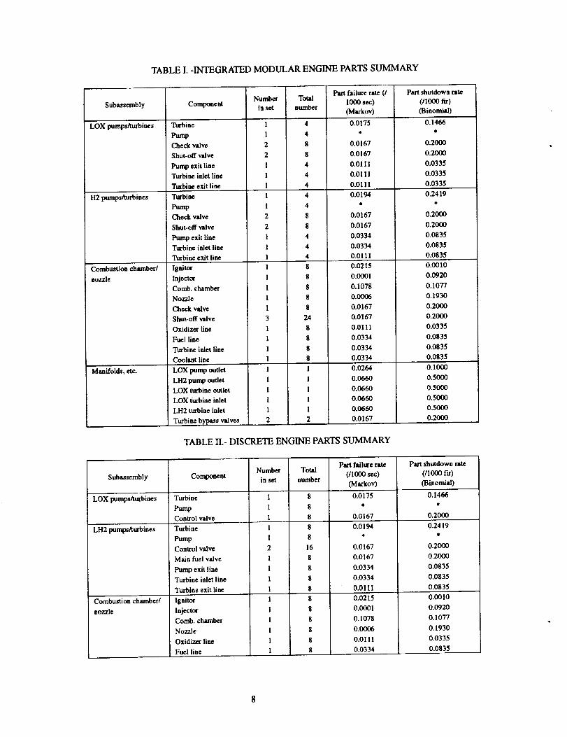
TABLE I. -INTEGRATED MODULAR ENGINE PARTS SUMMARY
Subassembly
LOX pumps/turbines
H2 pumps/turbines
Combustion chamber/
nozzle
Ug'_oid_,et_
Component
Turbine
pumpCheck valve
Shut-off valve
Pump exit line
Turbine inlet line
Turbine exit line
Turbine
PumpCheck valve
Shut-off valve
Pump exit line
Turbine inlet line
Turbine exit line
IgmtorInjector
Comb. chamber
Nozzle
Check valve
Shut-off valve
Oxidizer line
Fuel line
Turbine inlet line
Coolant line
LOX pump outlet
LH2 pump outlet
LOX turbine outlet
LOX turbine inlet
LH2 turbine inlet
Turbine bypass valves
Number
in set
Total
number
8
8
8
8
8
24
8
8
8
8
!
1
1
1
1
2
Part failure rate (/
1000 sec)
(Markov)
0.0175
J
0,0167
0.0167
O.OIIl
0,0111
0.0111
_0194
0.0167
0.0167
0.0334
&0334
0.0111
0.0215
0.0001
0.1078
0.0006
0.0167
0.0167
0.0111
0.0334
0.0334
0.0334
0.0264
0.0660
0.0660
0.0660
0.0660
0.0167
Part shutdown rate
(/I000 fir)(Binomial)
0.1466
0.2000
0.2000
0.0335
0.0335
0.0335
0.2419
,
0.2000
0.2000
0.0835
0.0835
0.0835
0.0010
0.0920
0.1077
0.1930
0.2000
0.2000
O.0335
0.0835
0.0835
0.0835
0.I000
0.5000
0.5000
0.5000
0.5000
0.2000
TABLE If.-DISCRETE ENGINE PARTS SUMMARY
Part failure rate Part shutdown rateNumber Total
Subassembly Co_nt in set number (/1000 sec) (/1000 f'Lr)(Markov) (Binomial)
LOX pumps/turbines Turbine 1 8 0.0175 0.1466
Pump l 8 * *
Control valve l 8 0.0167 0.2000
LH2 pumps/turbines
Combustion chamber/
nozzle
Turbine
Pump
Control valve
Ma/n fuel valve
Pump exit line
Turbine inlet line
Turbine exit line
Ignitor
Injector
Comb. chamber
Nozzle
Oxidizer line
Fuel line
8
8
16
8
8
8
8
0.0194
0.0167
0.0167
0.0334
0.0334
0.0111
0.0215
0.0001
0.1078
0.0006
0.0111
0.0334
0.2419
*
0.2000
0.2000
0.0835
0.0835
0.0835
0.0010
0.0920
0.1077
0.1930
0.0335
0.0835
IDNO.
7.1
ITEM/
FUNCTION
Oxidizer
PumpOutlet Mani-
fold
TABLE III.- EXAMPLE PAGE FROM FMEA FOR IME MANIFOLDS
FAILURE
MODE
7.1.1 Crack/fatigue7.1.2 Contamination
in ducting7.1.3 Flange distor-tion7.1.4 Contamination
of seals/sealing sur-face7.1.5 Seal failure
7.1.6 Fastener torquerelaxation
FAILURE
CAUSE
7.1.1 Fatigue, vibra-tion, thermal distor-tion, materialdefect, oversa'ess,
improper machining,weld anomaly7.1.2 ExternalSOurg¢, maaufacUlr-lag
7.1.30verpress_e,assembly error, ther-mal7.1.4 External
s_te'ge, manttfactur-lag7.1.5 Seal defect,assembly error,improper handling,oversu'eg$, neff-temp., damage tosealing surface7.1.6 Vibration,excess, load,
improper assembly,defect
FAIL.
FAILURE HAZ. RATE
EFFECT CAT. /1000
FIR
7.1.1 Leakage of IIoxidizer, fire, explo-sion, loss of oxidizerto chamber, loss of
prrformanc¢ormis-sion HI
7.1.2Blockage of
passages leading toreduced flow rates tochamber7.1.3 same as 7.1.1 II7.1.4 same as 7.1.1 II7.1.5 same as 7.1.1 II7.1.6 same as 7.1.1 II
ACTION
REQ.
7. I. 1 Structural
proof testing:safety factor of 1.4
7.1.2 Rigorousinspection; con-tamination con-
_'ol procedures7.1.3 Largedesign margins;leak checks priorto start; rigorousiRspection7.1.4 Leak checks
l_rior to operation;rigorous mspec.finn; contamina.tion control7.1.5 same as7.1.37.1.6 same as7.1.3 also self
locking nuts orinserts
ID
NO.
6.1
TABLE IV.- EXAMPLE PAGE FROM PHA FOR THE IME MANIFOLDS
HAZARD
CONDITION
Fire/Explosion 6.1.1 Leakage ofpropellants from:
a: Crack/fatigueb. Flange distortionc. Contamination of
seal/sealing surfaced. Seal failure
e. Fastener torquerelaxation
(FMEA sections6.1-6.14, 9.1,9.2)
6.1.2 Improper vent-ing and routing ofpropellants from:L Improper assem-
blyb. Vent gases reenterur collect in lines
HAZARD HAZ. HAZ. HAZARD
EFFECTS CAT. FREQ. CONTROLS
Leakage createsapotentially flamma-ble environment;instrumentationmay bm-a,prevent-ing system healthmonitoring: adja-cent hardware mayoverheat, leading tocracks/failures; total
system loss
Mixing of oxidizerand fuel may createa potentially flam-mable environment:instrumentation
may bin-n,prevent-ing system healthmonitoring; adja-cent hardware mayoverheat, leading tocracks/failures; total
system loss
II C
II D
Hardware designedto safety fact_xs of
1.1 in yield and 1.4in ultimate; contami-nation control proce-dures; stress analysisof manifolds; leak
checks prior to oper-ation; rigorousinspection tech-niques
All oxidizer andfuel lines will be
properly marked toprevent improperassembly; oxygenturbopump interpro-pellant seal assem-bly vent linepressures will bemonitored as redline
REMARKS
Manifold
Manifold
I
®
I
|
\
@®®®
8 THRUST CHAMBERASSEMBLIES TOTAL CONTROL VALVE
I;_ SHUT-O_FVALVE
r_ CHECK VALVE
(_) PUMP
(_) TURBINE
@ LOX PUMP OUTLET
@ LH2 PUMP OUTLET
(_ LOXTURBINE OUTLET
LH2 TURBINE INLET
(_ LOXTURBINE INLET
Figure 1.- IME schematic diagram, expander cycle configuration.
10
(
X 2L _.
,)
(,)
J
0--X(
,)
iI
(,)I
M...-..-|
/
8 THRUST CHAMBERS/16 TURBOPUMPS TOTAL
CONTROL VALVE
SHUT-OFF VALVE
N CHECK VALVE
(_ PUMP
TURBINE
Figure 2.- Discrete engine schematic diagram, expander cycle configuration.
I
11
1.000
.990
.980
.970 . , . , . , . , . i . ,
0 2 4 6 8 !0 12
Number of thrust chambers14
Figure 3.- Comparison of IME and discrete engine system reliability,no redundancy.
1°000.
.999'
.998.
.997.
.996"
Discrete
6 •16Oe°B_°Wl,Wjll *UlltOllWjj°O,Ij.OOO_I_**_ _ Qe°*Jt°gUll.
IME
.995 - ,,, • • • , .. , . ,o 2 _ _ _ ,o ,2 ,4
Number of thrust chambers
Figure 4.- Comparison of IME and discrete engine system reliability,one thrust chamber out, one turbopump out.
12
1.000
.999
.998
.997
Discrete
valves
IME
.996 • , ' " ' " ' " '
0 .1 .2 .3 .4 .5
Valve shutdown rate (per 1000 firings)
Figure 5.- Effect of valve shutdown rate on system reliability, one thrustchamber out, one turbopump out.
1.000
.999
.998
.997
0
Discrete
IME, redundant
turbine bypass valves
"%
.1 .2 .3 .4 .5
Manifold shutdown rate (per 1000 firings)
.6
Figure 6.- Effect of manifold shutdown rate on system reliability, onethrust chamber out, one turbopump out'.
13
Po,0_ p _ i "_ _ P3,3
Po,f_ z / P3,1'
P_ = 1.0
Figure 7.- Sample state space diagram.
..-4
1.0 _0
-] • aa o Discrete
_-I " _ . _E
1-'.6
•,t : X_o _
0 I ' - w " ! ' I -- I ' "_'''''_" ........
0 10(X) 2000 3000 4000 5000
Firing duration, sec
000
Figure 8.- Reliability comparison of discrete and IME concepts.
14
1.00
.95
.80
.75
0
m -- --: = : _ _ _ = = = = = - - m - m II m m m
• o• 0
0@ 0
• @o
0,0
0
• •
0
0
0
0
O
@
• Discrete
o IME, failure rate = 0.0/sec
• IME, failure rate = 0.3238/1000 sec
lob 280 3ob 400 500
Firing duration, sec
Figure 9.- Single-point failure effect on IME system reliability.
o
1.00
.95
.80
.750 60
I
o Baseline, 0.3 failures/1000 sec
"_'x o • 2x Manifold failure rate[] 2x TCA failure rate
° o o AixlAfailurerate
120 180 240 300
Firing duration, sec
Figure 10.- ME system reliability sensitivity to componentfailure rate.
15
l.O ,_
QO
0 °
.8- O
@
• •
• O
.15• @
o 100% Effective Health Monitoring• 80% Effective Health Monitoring
.4
.2
• • i0o0
00 OOo
• 0@o• 0
• O0 o
4l,• OOoo0000Oooonn_ A,
500 1000 1500 2000 2500 3000
Firing duration, sec
Figure 11.- Health monitoring effect on IME system reliability.
I
J FAILURE OF /
!c.,,mERn,_V_l[ voclvEa',_UsT I
I FAI_o%_Oo_'_I
_u_ I
I I I I
i- iPROVIDE FLOW PROVIDE PLOW J
,z,
FAILURE OF IM E J
MANIFOLDS J
Qf 1
LOSS OF VALVE I [ FAILURE OF ]AC'FUATOR J THRUSTPNEUM.PRESS. J CHAMBERS
,_, cO
I I
I ,, i-PNEUM.PRE.SS. J I TURBOPUMPS
_, qJ! i
TURBOPUMP #1 TURBOPUMP #1
2,, /,,
I
A
I
LOSS OF THRUST l
CHAMBER 1"2 J
2,,! !
^cru^ro_ II LoxPNEUM.pRESS. J | TURBOPUMPS
_x r4i I 'FAILURE OF
MANIFOLD # I
| I
LOSS OF LOX TURBOPUMP #2 ITURBOPUMP #l
A zX
I 1 1 /k%_AILo,Eo_i Z_ i _AILUR_o:iM,_,_o_,#2I I M_o_, I
/,, /,,
Figure 12.- Sample page from IME fault tree.
16
l I©
AA:
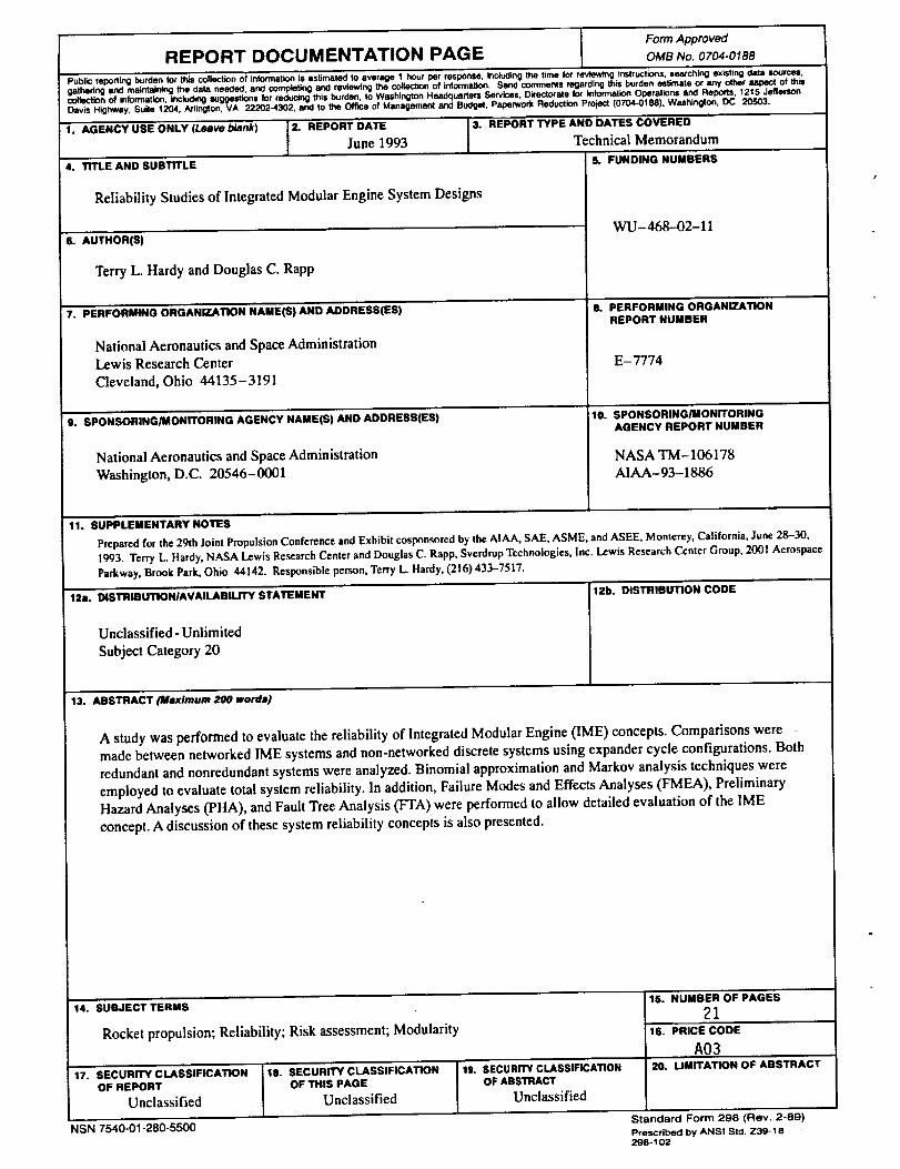
AND gate - Output fault occurs if all the input faults occur
OR gate - Output fault occurs if at least one of the input faults occur
BASIC EVENT - Basic initiating fault event that requires no furtherdevelopment
TRANSFER IN - Indicates that the tree is developed further at theoccurrence ot the corresponding TRANSFER OUT
TRANSFER OUT - Indicates that this portion of the tree must be attachedat the corresponding TRANSFER IN
Figure 13.-Fault tree symbols.
17
Form ApprovedREPORT DOCUMENTATION PAG E OMB No. 0704-0188
PL_IJC reporting burden for th_ collection of tnformal_n"ls astimaled to average 1 ho_rTper resporse_ I_cluding the time f_' reviow_g InstruCtiOnS, searching exiting data Iources,
gathering and maintaining the data needed, and completing and reviewing the collection of information. Send comments regarding this burden estimate or any other _pecl of this
collection of information, including suggestions for reducing this burden, to Washington Headquarters Services. Directorate for Information Operations and Reports, 1215 Jefferson
Davis Highway. $u/te 1204, Arlir_on, VA 22202.4302, and to the Offme of Management and BuCget. Paperwod( Reduclio_ Proje¢l (0704-0188). Washington, DC 20503.
1. AGENCY USE ONLY (Leave blank) 2. REPORT DATE I 3. REPORT TYPE AND DATES COVERED
June 1993 [ Technical Memorandum4. TITLE AND SUBTITLE 5. FUNDING NUMBERS
Reliability Studies of Integrated Modular Engine System Designs
6. AUTHOR(B)
Terry L. Hardy and Douglas C. Rapp
7. PERFORMING ORGANIZATION NAME(S) AND ADDRESB(ES)
National Aeronautics and Space Administration
Lewis Research Center
Cleveland, Ohio 44135- 3191
9. SPONSORING/MONITORING AGENCY NAME(S) AND ADDRESS(EB)
National Aeronautics and Space Administration
Washington, D.C. 20546-0001
11. SUPPLEMENTARYNOTES
WU- 468--02-11
8. PERFORMING ORGANIZATIONREPORT NUMBER
E-7774
lo. SPONSORING_aONITORINOAGENCY REPORT NUMBER
NASA TM-106178
AIAA-93-1886
Preparedfor the 29th Joint Propulsion ConferenceandExhibit cosponsoredby the AIAA, SAE, ASME, andASEE, Monterey, California, June 28-30,1993. Terry L. Hardy, NASA Lewis Research Center and Douglas C. Rapp, Svcrdrup Technologies, inc. Lewis Research Center Group, 2001 AerospaceParkway, Brook Park, Ohio 44142. Responsible person, Terry L. Hardy, (216) 433-7517.
12a. DISTRIBUT_NIAVAILABILITY STATEMENT 12b, DISTRIBUTION CODE
Unclassified - Unlimited
Subject Category 20
13. ABSTRACT (Maximum 200 words)
A study was performed to evaluate the reliability of Integrated Modular Engine (1ME) concepts. Comparisons were
made between networked IME systems and non-networked discrete systems using expander cycle configurations. Both
redundant and nonredundant systems were analyzed. Binomial approximation and Markov analysis techniques were
employed to evaluate total system reliability. In addition, Failure Modes and Effects Analyses (FMEA), Preliminary
Hazard Analyses (PHA), and Fault Tree Analysis (FTA) were performed to allow detailed evaluation of the IME
concept. A discussion of these system reliability concepts is also presented.
14. SUBJECT TERMS
Rocket propulsion; Reliability; Risk assessment; Modularity
17. SECURITY CLASSIFICATION 18. SEC'URITY CLASSIFICATIONOF REPORT OF THIS PAGE
Unclassified Unclassified
NSN 7540-01-280-5500
19. SECURITYCLASSIFICATIONOF ABSTRACT
Unclassified
15. NUMBEROF PAGES
21t6. PRICE CODE
A0320. LIMITATION OF ABSTRACT
Standard Form 298 (Rev. 2-89)Prescribed by ANSI Std Z39-18
298-102