reliable evaluation of the acceptability of the weld for
TRANSCRIPT
5th European-American Workshop on Reliability of NDE – Lecture 37
1 License: http://creativecommons.org/licenses/by-nd/3.0/
Reliable Evaluation of the Acceptability of
the Weld for Final Disposal Based on the
Canister Copper Weld Inspection Using
Different NDT Methods
Jorma PITKÄNEN *, Marija BERTOVIC **, Daniel BRACKROCK **,
Gerhard BREKOW **, Uwe EWERT **, Daniel KANZLER **, Christina MÜLLER **
* Posiva Oy, Eurajoki, Finland
** BAM Federal Institute for Materials Research and Testing, Berlin, Germany
Abstract. The inspection of the sealing weld is an important phase for the
evaluation of the acceptability of final disposal canister, but the weld is only a part
of the 3D-shielding of copper shell. The main tasks for reliable NDT evaluation
requires an extensive parameters evaluation - which contains typical inspection
related items like repeatability, S/N-ratio, POD, setting up the equipment for
inspection and all practices for inspections. The other parameters are material
parameters, the variation of which must be taken into account in the evaluation of
NDT-reliability. Further parameters include human factors and their interaction with
technical systems; the effects of which were studied on an example of the evaluation
of eddy current data. Final parameters are related to evaluation of detected defects,
which means sizing and base for acceptance and this can be done in different ways.
Some examples are given and results are compared with different methods for
instance between radiographic testing and ultrasonic testing with raw data analysis
and PA-SAFT results. Also preliminary curves for the evaluation of 55-defect
metallographic results will be shown from EB-weld measurements. Some practical
items concerning copper inspections will be also discussed related to acceptability.
Introduction
The disposal canister should hold its tightness for at least 100 000 years. A good and long
lasting tightness is requiring [1]:
• A good original tightness (with high quality requirements and extensive
inspections),
• A good corrosion resistance (use oxygen-free copper as copper material),
• Sufficient mechanical strength (ensure with tensile tests or similar).
The canister is foreseen to decrease the radiation exposure on the outer surface of
the canister, in order not to limit the handling or transport of the canister excessively.
The NDT inspection of the copper tube, lid and lid weld plays an important role for
the acceptance of nuclear fuel disposal canister. The most important parameters for the
acceptance of disposal canister sealing welds based on NDT results of several methods are
discussed in this study. These parameters have been discussed earlier [2]. There are two

2
main reasons for the inspection of these components: Proper manufacturing and handling of
occurring defects of components. To accept and reject the copper components and welds
the defect sizing is a necessary process in order to compare the inspection results to
requirements and inspection specifications. The inspection procedures have been produced
during the development of the inspection techniques. The aim of the inspection method
development is to qualify the inspection techniques, defect detection and sizing procedures
according to ENIQ in order to show the inspection capability to fulfill all requirements. At
the moment the study of technical justification for the qualification purposes is going on. At
the same time the defect catalogue will be gathered and experience will be gained from
Posiva's test manufacturing and welding by doing NDT measurements. To inspect copper
welds ultrasonic, radiographic, visual and eddy current testing techniques are applied.
Additional informations are gained by combining the results of applied NDT-methods
together. At the moment the simple idea is to combine the results of analyzed data and
qualified inspectors. The acceptability of the weld will be considered after the combination
of these results.
In the acceptance of the sealing weld of the disposal canister the sizing by different
NDT methods plays an important role. With low inaccuracy of sizing either unnecessary
expensive rejection or acceptance of non-valid sealing welds can be avoided. Sizing results
should be confirmed by metallographic studies (Figure 1) [3].
Figure 1: Metallographic study of detected defects
The basic ultrasonic inspection will be carried out with linear phased array probes.
For sizing different ultrasonic techniques will be applied and all sizing tasks are carried out
with the phased array probes [4]. Also the advanced sizing technique phased array SAFT
can be applied [5]. The sizing principles of applied eddy current method have been
discussed in another study [6, 7]. The radiographic inspection has been presented in
Budapest 2007 [8] and visual inspection in Seattle 2012 [9]. The grain size variation gives
additional challenges to ultrasonic testing and this can make sizing more difficult [10]. The
inspection requirement concerning the defects of components and welds and also the basics
of the applied ultrasonic sizing techniques will be discussed.
The acceptance and rejection process based on the NDT is necessary. The
acceptance criteria are mainly under development. Some preliminary criteria have been
given for the thick copper weld inspection in the [11] but this work continues. The sizing of
the defects will be most important in acceptance of the components and welds based on
NDT results.
3
1. Parameter affecting the NDT reliability in mechanized inspections
A lot of parameters affect the NDT reliability especially in mechanized inspection. Some of
the typical parameters in mechanized inspections are repeatability, signal to noise ratio
(S/N), probability of detection (POD), set up the equipment for inspection and all typical
practices in inspections which are included in the procedures.
Posiva has tested the repeatability of measurements for example by starting 10 times
to set up probe positions and carry out measurement. The probe position error in Posiva's
weld manipulator is about 1 mm. This can be checked by analyzing the indications of the
known reference defects in each data set. Unfortunately these repeatability tests cannot
directly be used for POD determination because the reference defects are the same as well
as equipment and probes. The NDT reliability of inspections is in two ways affected from
S/N: Firstly in defect detection secondly in sizing. In defect detection a low signal to noise
ratio makes the decision to distinguish between a signals from the defect and noise more
difficult for the inspector. Low S/N ratio makes the sizing process more difficult for
instance in case of shallow cracks. Shallow crack surfaces are pressed together which
makes it difficult to size it properly for almost all of the applied NDT methods. In this case
especially the defect size in corrosion direction is not easy to measure. The corrosion
direction is shortest way from outer surface of the copper shell to inner surface of the
copper shell.
The common way to form a POD - curve is to apply a sufficient amount of
reference defects [12, 13] as a minimum of 35 - 40 reference defects in the corresponding
POD-experiment. This can cause quite expensive reference specimen. To avoid too high
costs other approaches have been studied compared to the conventional POD process [14].
In order to reduce the human factor effect (in this case negative effect) decision aids will be
studied. These kinds of aids could be a defect catalogue, improved simplified inspection
procedures, clear information in order to help the inspector to avoid to make mistakes
during the set up of the equipment or setting other parameters of the inspections [15].
Even though all typical parameters of the inspections are in acceptable range, the material
can contain variations which vary the S/N ratio like coarse grained material or variation on
the object surface conditions. These parameters must be taken into account in the
evaluation of NDT-reliability.
Human factors and their interaction with technical systems can affect strongly the
inspections. The more complicated the measurement systems is the more complicated the
human factor effect can be. These human factor effects were studied for instance during the
evaluation of eddy current data [16]. A number of important parameters which are derived
from the evaluation of detected defects are taken as a base for the acceptance of the
component. In the following some examples where different NDT-methods are compared
with each other are considered for this purpose.

4
Figure 2: Technical parameters affecting the reliability of mechanized inspections
2. Sizing
The evaluation of indications and sizing of the defect has to be carried out in order to be
able to accept or reject object. Sizing will be carried out by different methods: Using
ultrasonic, radiographic and eddy current and visual testing. The sizing coordinates are
circumferential, axial and radial because the inspection object is rotationally symmetric.
2.1.Sizing in ultrasonic testing
Posiva has tested the following sizing methods in copper components and copper welds. In
ultrasonic testing the sizing can be carried out by using different techniques like 6 dB
method, tip diffraction, TOFD, or with several advanced systems like SAFT, Sampling
phased array, PA-SAFT Focused matrix PA approach. The raw data analysis of phased
array data is shown in Figure 3. Typically the ultrasonic software's contain geometrical
information from the object which makes it easier to differentiate the indications from each
others.
Figure 3: Raw data evaluation of phased array ultrasonic data
The most accurate sizing methods is based on the evaluation of diffraction signals.
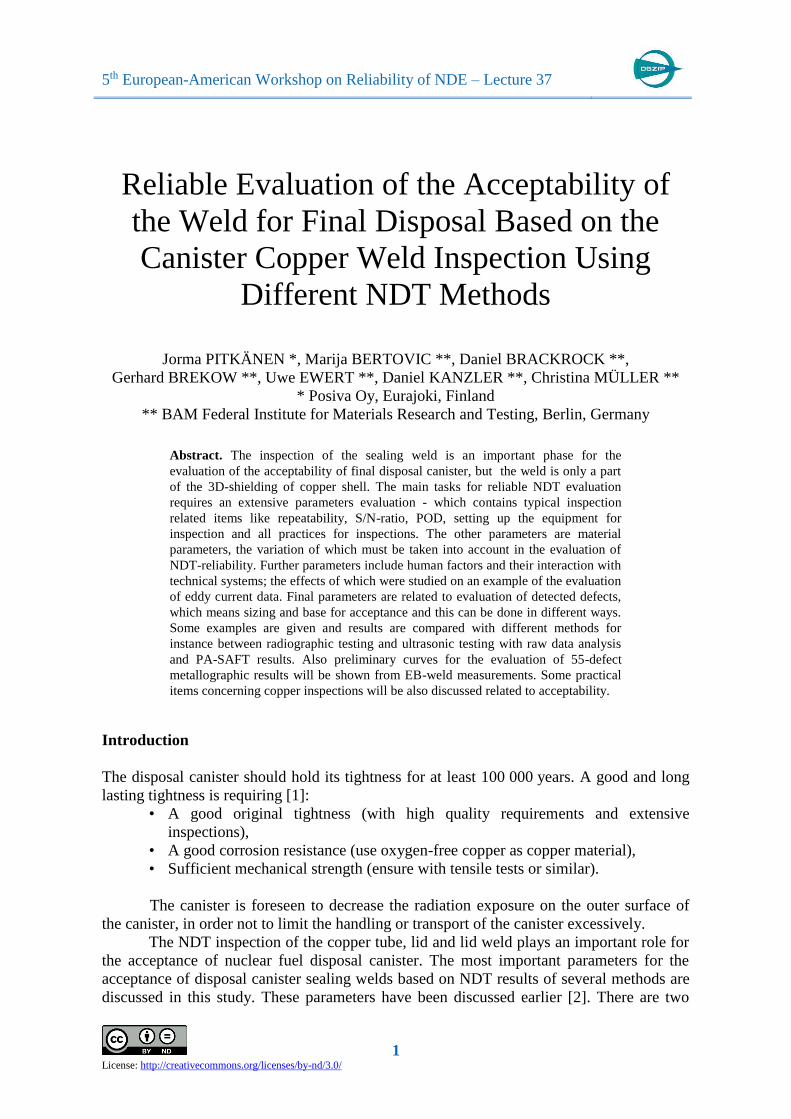
TOFD is a special application of diffraction techniques. Figure 4 shows the setup for TOFD
by using PA probe. The applied method is discussed more thoroughly in [5]. The
5
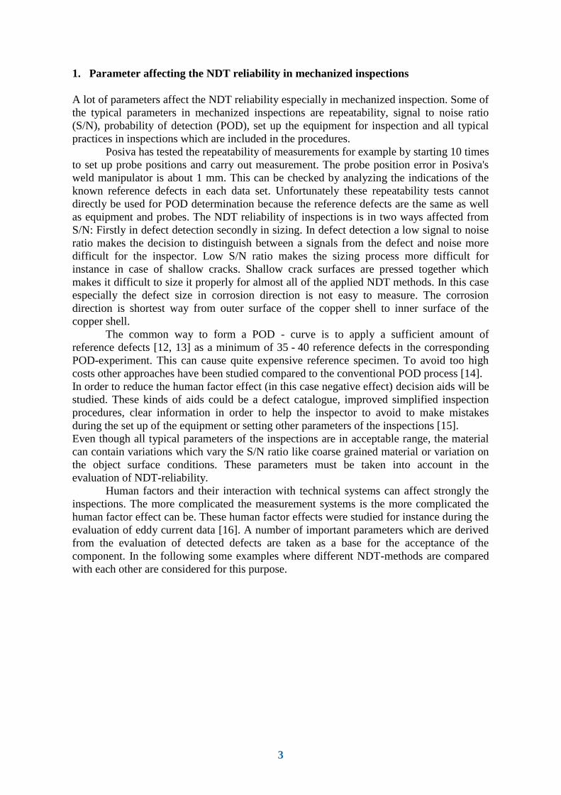
evaluation of TOFD data is based on the difference of the reference wave (lateral wave,
back wall echo) and the defect signal (Figure 5, left). Based on this time difference (time of
flight) a sizing curve can be produced based on known defect sizes (Figure 5, right). The
calibration curve shown in Figure 5 is produced by measuring surface breaking notches of
different sizes from 1 mm to 15 mm in depth. It can be seen that the set up (separation of
the probes, active element size) must be changed, when the defect depth exceeds 10 mm in
order to keep the inaccuracy as small as possible.
Figure 4: TOFD measurement set up for a phased array probe
Figure 5: Evaluation and sizing with TOFD calibration
Phased array SAFT is one of the advanced sizing systems. SAFT Systems contain
hardware, and data acquisition and evaluation software developed by BAM. In the SAFT
reconstruction the signal to noise ratio from defects will be improved with the help of
signal averaging. For SAFT measurements typically small conventional probes has been
used. With the help of angular scanning of phased array signals it is possible to use SAFT
reconstruction for data evaluation. This technology has been developed and reported for
many applications by the BAM Berlin, who applies the phased array SAFT (PA-SAFT)
also in this work. In PA-SAFT several angles of incidence are computed together producing
a large sound field. Each angle of incidence can be separately computed in order to improve
the signal to noise ratio. Along one measurement line a sufficient large aperture for SAFT
reconstruction can be produced this way. BAM has made measurements for Posiva from
electron beam (EB) copper weld samples, Figure 6. Typically, this kind of advanced back
propagation reconstruction system produces quite accurate positioning of defect signals.
Signals coming from materials with anisotropic properties make the reconstruction a bit
inaccurate, even though it is possible to model anisotropy and take it into account in
reconstruction. This is because in technical systems the anisotropy varies typically from
position to position and so some inaccuracy is always present in evaluations of ultrasonic
data. Figure 6 (right) shows a reconstruction from EB-weld containing three side drilled

6
holes having different diameters ( = 1 mm (H13), 0.52 mm (H12), 0.40 mm (H11)). The
weld noise (material noise from coarse grained weld) can be seen in the reconstruction as
an increased green-yellow color in C-scan in Figure 6 (middle).
Figure 6: Evaluation and sizing of electron beam weld defects by PC-SAFT
2.2.Sizing in radiographic testing
Radiographic testing will be used mainly for weld testing. In the radiographic inspection
system the canister rotates, while the accelerator generates X-rays penetrating through the
copper EB-weld with an angle of 10°, and through FS-weld with an angle of about 30. The
main components of the system are:
• Varian’s 9 MeV linear accelerator,
• Manipulator for positioning of accelerator and detector,
• Detector system consisting of a collimated vertical line-camera,
• Computer system for setting up the inspection and evaluation of results.
The line camera (detector) collects the transmitted X-rays and an X-ray image with
an 0.4 mm resolution is created. A collimator is placed in front of the accelerator to focus
the beam and the detector is placed into a housing of tungsten to reduce the scatter. The X-
rays pass through the 70 mm housing through a 0.4 mm wide vertical slit. As the penetrated
thickness varies in the X-ray inspection of the weld, a thickness correction is made to
calibrate the system. The correction is made by a mean value calibration from 500 samples
around the weld circumference. The sizing of the indications detected in X-ray inspection is
carried out according to the scheme in Figure 7. In the two dimensional image the detected
indications are evaluated in the indicated red box providing the information on
circumferential (marked with C = circumferential direction) and axial measures (marked
with A = axial direction) of the defects. The dimension in radial direction can be estimated
from the gray values based on the calibration curve of known calibration defect dimensions
in X-ray direction (Figure 8, curve on the right).
Figure 7: Evaluation and sizing of radiographic indication

7
2.3.Sizing in eddy current testing
The evaluation scheme of eddy current signals is based on the scheme shown in Figure 8
(right). The surface size of defects (length x width) will be detected and sized using high
frequency coils (30 kHz). The depth of surface breaking defect is determined by
investigating the indication detected with the low frequency coil. The indications of several
defects in the polar coordinate presentation show how the angle of indications reveal the
depth of the defects (200 Hz) [7]. The inaccuracy of depth sizing is under study. As seen in
Figure 8, the indications will saturate at the depth of approximately 10 mm for surface
breaking defects. This means that it is possible to estimate the depth of the indications up to
10 mm but for deeper defects the reliability decreases clearly. It is also possible to
distinguish between volumetric and planar types of defects. These two types of defects have
specific defect depth sizing curves each. So it is important first to evaluate the type of
indication and surface area of the defect to improve the sizing accuracy. Often experience
has shown that the indications have both planar and volumetric characteristics, which
complicates the evaluation.
The evaluation of the defect size can be based either on the measured amplitude or
on the angle of the indication. The welding process and machining after welding can
produce also defects, which doesn't open to the surface, which means that there is a so
called ligament between defect and surface. If this ligament is not too thick (up to 5 mm)
the defects can be detected in the eddy current testing. The ligament thickness can be
evaluated from the angle of the indications and it is quite linearly proportional to angle
changes.
Figure 8: Evaluation and sizing of eddy current Indication
2.4.Sizing in visual testing
The sealing weld between copper lid and copper tube might be welded with electron beam
welding (EBW) or friction stir welding (FSW) technique. Visual inspection of the copper-
weld will be carried out as a remote inspection due to the radiation from the nuclear fuel.
General advantages of remote visual inspection compared to direct visual inspection are the
possibility to mechanize the inspection and the possibility to record inspection data that can
be reviewed at later stages. Also position information can be recorded together with the
data.
At this particular inspection task the main challenges of inspection are the radiation
of the inspection object and the requirement to find relatively small surface defects from the
highly reflective (light) machined copper surface with an adequate probability of detection.
8
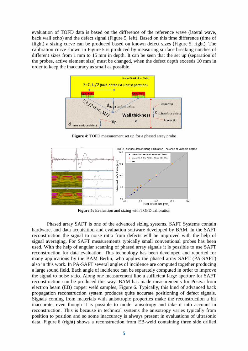
The primary purpose of the remote visual inspection is to detect weld imperfections
that are open to the surface of the weld. Another important task is to detect imperfections
that might originate from the handling operations of the canister. Data acquired with remote
visual inspection can be reviewed at later stages and also be used to assist the analysis of
indications detected with other NDE methods such as eddy current testing, ultrasonic
testing and radiographic testing. The size of detected defects can be measured and
evaluated from the image in circumferential and radial direction (Figure 9).
Figure 9: Visibility of 0.1 x 1.5 mm (w x l) notch with 7.5 x magnifications (0.5 º/s)
3. Combining of results of several NDT methods
Each Posiva's applied NDT-method produces individual results from detected defects as a
first phase of inspection evaluation. In the second phase all detected defects are evaluated
either by applying proximity rules from ASME XI [17, 18] or possible sizing inaccuracy of
the used NDT method [11]. After the evaluation of proximity rules the final defect sizes are
determined in each NDT method. After this phase each defect indication will be considered
and possibly combined with defect indications produced by other NDT methods
(Figure 10). This combination of results of different NDT methods will be carried out by
jointly by specialists of all applied NDT methods. This type of procedure was accomplished
for 55 defects and the combined size of those defects has been plotted against results from
metallographic results in Figure 11. The curve seems to be a bit conservative. This means
that in average the defect sizes were a little bit oversized. This can cause a small tendency
to reject too often keeping the safety as a major item. But in these 55 selected samples also
3 defects were too much undersized. The metallographic result gave a defect size of 20 mm
and the NDT result was 8 mm. All these undersized defects will be studied more carefully
than other indications. In all cases the combination of defects were carried out after raw
data analysis. In the combining phase not any advanced sizing method was applied. In the
procedure the limit for advanced sizing was at first chosen to be 10 mm but after this
detection of undersizing it was lowered to 8 mm.

9
Figure 10: Combining of indications with four NDT methods
We consider the example of the EB-weld specimen (Xk033). It was X-rayed with a
9 MeV linear accelerator and also inspected with PA-SAFT. About the same defects were
detected with both methods. Some extra indications were seen in the phased array SAFT
results (Figure 12). According to the elaboration from metallographic studies some small
defects have been detected in metallographic studies but not in the X-ray inspections or
using the normal linear phased array inspections. According to the metallographic studies
these defects are mainly in radial direction. It seems that PA-SAFT provides also the
detection of these type of defects. These defects are quite thin and also three dimensional
which means that in X-ray inspection they are not necessarily optimal for detection. The
Phased array SAFT can be improved by using matrix phased array so that angular scanning
can be performed in two axis directions (circumference and axial directions). Alternatively
a matrix phased array having several focus depths can be applied yielding similar results as
PA-SAFT for this inspection.
Figure 11: Metallographic size compared to defect size received in NDT evaluation
NDT-Inspection
VT
Measurement
Datastorage
Analysis
of data
3D positioning
of indications
ET
Measurement
Datastorage
Analysis
of data
3D positioning
of indications
UT
Measurement
Datastorage
Analysis
of data
3D positioning
of indications
RT
Measurement
Datastorage
Analysis
of data
3D positioning
of indications Combiningof defects

10
Figure 12: images of real defects by applying PA-SAFT (C-scan in upper part of the image) and X-ray image
(lower part of the image)
4. Acceptance and rejection process based on NDT indications
The NDT acceptance of the component can be divided into:
• the requirements caused by the occurring defects for the choice of the inspection
technique,
• the defect detection analysis after inspection,
• the defect sizing,
• the comparison of the inspection results to the acceptance criteria.
The final disposal canister master requirement is shown in Figure 13. According to
it the defect size should not exceed 15 mm or the remaining wall thickness should be at
least 35 mm.
Figure 13: Master requirement of the disposal canister for acceptance rejection process.

11
This preliminary acceptance - rejection process of copper components and copper
welds divided in four sections is also depicted in Figure 14. In copper weld inspections four
methods for defect detection will be applied: visual, eddy current, ultrasonic and
radiographic testing. After the measurement the first analysis is based on the raw data
analysis. If the indications are clear and acceptable the component or weld can be accepted.
In case of indications exceeding the acceptance criteria further analysis will be carried out
in order to measure the minimum wall thickness. The defect will be evaluated by applying
advanced sizing methods more accurately. Some of these methods have been mentioned in
previous chapters. If the indication is acceptable after this analysis the component will be
accepted. In case the indication is not acceptable but it is not clearly rejectable a deviation
assessment will be carried out. The material experts will be also involved in the deviation
assessment besides the NDT experts before final acceptance or rejection is made. Special
cases might occur if the defect exceeds the acceptance criteria but is situated so that it's
presence does not cause problems in long term safety issues. In this case the component
deviation assessment will be guided to the authority handling. In case the deviation
assessment process results in the statement the component fulfils the acceptance criteria the
component can be accepted by the licensee.
Figure 14: Acceptance and rejection process of copper components according to the evaluation of NDT
indications.
Weld surface defects not exceeding the master requirements can be possibly
smoothly grinded and removed not exceeding acceptance limits. This type of repair process
might possibly need a deviation assessment.
12
5. Summary and Conclusions
A lot of parameters affect the NDT reliability. The mechanized inspection system is much
more complicated than manual inspection. The Human factor effect can be considered in all
phases of mechanized inspections: preparation for inspection, data acquisition, data analysis
phases.
The POD provides essential information for the inspection capability to detect
defects. Posiva will study the POD for each applied NDT method and possibly for
combined results of four NDT methods.
The sizing is the most important phase in acceptance and rejection of the sealing
weld. By right choice of advanced sizing method the uncertainty can be reduced. By
minimizing the inaccuracy in sizing either unnecessary rejection or safety related wrong
acceptance can be reduced. A bit conservative oversizing was noticed in combining of
indications by four NDT methods on the basis of raw data analysis, which is an excellent
result from the safety point of view. The preliminary acceptance rejection process based on
NDT results was presented and already applied for test weldings. A possible repair is only
applicable for surface breaking defects. The sizes of these surface breaking defects must not
exceed the acceptance criteria as well as after repair the remaining wall thickness must not
exceed the master requirements. The result of the repair on the surface must be smooth and
defect free.
References
[1] Raiko, H., 2013. Canister Design 2012. Report POSIVA 2012-13, Posiva Oy.
[2] Pitkänen J., Salonen T., Bertovic M., Müller C. and Pavlovic M., NDT Reliability in Risk Minimization
during Manufacturing and Welding of Spent Nuclear Fuel Disposal Components - A Realistic Tool for
Reliable Inspections, 4th European-American Workshop on Reliability of NDE, 24th - 26th June 2009. Berlin
Germany 21p.
[3] Pitkänen, J.; Paussu, R.; Pohjanne, P.; Virkkunen, I.; Kemppainen, M.; Lipponen, A.; Sarkimo, M.;
Simola, K. and Reddy, K.-M. Metallographic study of Detected Indications in EB-Copper welds for Verifying
the NDT Reliability of Inspection 8th International Conference on NDE in Relation to Structural Integrity for
Nuclear and Pressurized Components 29th September 1st October 2010, Berlin German
[4] Pitkänen J., Salonen T., Lipponen A., Sarkimo M. and Paussu R., Ultrasonic testing of copper welds, 8th
International Conference on NDE in Relation to Structural Integrity for Nuclear and Pressurized Components
29th September 1st October 2010, Berlin Germany
[5] Pitkänen J., Lipponen A., Raiko H., Brekow G. and Brackrock D., Defect sizing using PA-ultrasonic
testing and acceptance in copper lids, tubes and welds for disposal canister, 10th International Conference on
NDE in Relation to Structural Integrity for Nuclear and Pressurized Components October 1st - 3rd 2013,
Cannes France 11p.
[6] Pitkänen J., Lipponen A., Lahdenperä K. and Kiselmann I., Eddy current inspection for detection of
surface and near surface defects in copper components and an electron beam welds 7th international
conference on NDE in relation to structural integrity for nuclear and pressurized components, 12th - 14th .
May, 2009 Yokohama Japan. 13p.
[7] Pitkänen J., Lipponen A., Lahdenperä K. and Kiselmann I., Detection and sizing in copper components
using Eddy current, 9th international conference on NDE in relation to structural integrity for nuclear and
pressurized components, 22th - 24th. May, 2012 Seattle USA.
[8] Pitkänen J, Salonen T, Sandlin S and Ronneteg U, “Defect detectability in EB-welded copper disposal
canister with 9 MeV accelerator”, 6th International Conference on NDE in Relation to Structural Integrity for
Nuclear and Pressurized Components, Budapest, 12th -14th October, 2007. 14p.
[9] Pitkänen J., Paussu R., Seppälä P., Saastamoinen T., Kanzler D. and Müller C., Remote visual inspection
of disposal canister EB weld, 9th international conference on NDE in relation to structural integrity for
nuclear and pressurized components, 22th - 24th May, 2012 Seattle USA
[10] Pitkänen J., Arnold W. and Hirsekorn S., The effect of grain size to defect detectability in copper
components in ultrasonic testing, 6th International Conference on NDE in Relation to Structural Integrity for
Nuclear and Pressurized Components, Budapest, 12th -14th October, 2007. 14p.
13
[11] Pitkänen J. Posiva Report 2010-04, Inspection of bottom and lid welds for disposal canisters, September
2010, 98p.
[12] MIL-HDBK-1823A, “Nondestructive evaluation system reliability assessment”, Department of Defense
Handbook, 2009
[13] Berens A P, NDE Reliability Data Analysis – Metals Handbook, Volume 17, 9th Edition: Nondestructive
Evaluation and Quality Control, ASM International, OH, 1989
[14] Kanzler D., Müller C., Pitkänen, Evaluation of radiographic performance with an advanced POD
approach, 5th European-American Workshop on Reliability of NDE, 7th - 10th October 2013. Berlin
Germany 6p.
[15] Bertovic Marija, Müller C., Fahlbruch B., Ronneteg U. and Pitkänen J., Holistic risc assessment and risc
prevention approach to the mechanized NDT and the inspection procedure, 5th European-American
Workshop on Reliability of NDE, 7th - 10th October 2013. Berlin Germany 11p.
[16] Bertovic Marija, Human factors in NDT of the EB-weld, Posiva Report 2012-38, 111p (to b published).
[17] ASME XI 2013, Article IWA3300 Standards for examination evaluation, Rules for inservice inspection
of nuclear power plant components, American society of mechanical engineers, New York, pp. 14-25.
[18] Pitkänen J. Posiva Report 2012-35, Inspection of disposal canisters components, December 2013, 95p.