reliable model-driven engineering using iec...
TRANSCRIPT

Reliable Model-drivenEngineering using IEC 61499
Gareth Darcy Shaw
February 2013
Supervisors: Partha S Roop
Zoran Salcic
Department of Electrical and Computer EngineeringThe University of Auckland
New Zealand
A thesis submitted in partial fulfill-
ment of the requirements for the de-
gree of Doctor of Philosophy in Engin-
eering


The University of Auckland
Thesis Consent Form
This thesis may be consulted for the purpose of research or private study provided that
due acknowledgement is made where appropriate and that the author's permission is
obtained before any material from the thesis is published.
I agree that the University of Auckland Library may make a copy of this thesis for supply
to the collection of another prescribed library on request from that Library; and
1. I agree that this thesis may be photocopied for supply to any person in accordance
with the provisions of Section 56 of the Copyright Act 1994.
Or
2. This thesis may not be photocopied other than to supply a copy for the collection
of another prescribed library.
(Strike out 1 or 2 )
Signed: . . . . . . . . . . . . . . . . . . . . . . . . . . . . . . . . . . .
Date: . . . . . . . . . . . . . . . . . . . . . . . . . . . . . . . . . . . . .
Created: 5 July 2001
Last updated: 9 August 2001
Abstract
Complex industrial control systems, such as those used in airport baggage handling sys-
tems (BHSs), need to be designed in a way to ensure that they avoid failures. Even small
failures in such systems may result in serious economic and social consequences due to
delayed �ights and lost bags. Consider, for example, the problems caused by failures in
the BHS during the opening of a new terminal at Heathrow airport in 2008. The com-
plexity of BHSs has also grown over the years, as exempli�ed by the BHS of Schiphol
airport, which can handle up to 70 million bags in a year.
Model driven engineering (MDE) is a modern design approach that is being touted as
the next generation design methodology to deal with design complexity. MDE focuses on
the speci�cation of graphical and high-level models, often based on sound mathematical
principles, from which low-level implementations are automatically derived. The use of
automated code generators makes systems developed using MDE tools and techniques
inherently platform and network agnostic. For safety-critical applications, designers also
have access to many high-level veri�cation and validation (V & V) techniques to validate
the correctness of designs. MDE is already being used to provide robust designs, while
meeting time to market pressures. MDE is the main theme of this thesis, and its usage
will be illustrated in the design of complex control systems such as airport BHSs.
Unlike the MDE approach, industrial control systems are traditionally designed using
low-level languages such as the IEC 61131-3 standard. These languages, while suitable for
small to medium scale control systems, are inherently more di�cult to design, deploy and
maintain compared to MDE-based approaches. IEC 61499 is a recent open standard that
is proposed to facilitate a component-based graphical approach for the design of industrial
control systems. This thesis adopts IEC 61499 as the main basis for an MDE-based
development approach. However, the standard lacks rigorous mathematical semantics that
is the cornerstone of MDE. Hence, this thesis makes two key contributions, as outlined
below:
(a) A denotational, compositional semantics for IEC 61499 function blocks is proposed.
The proposed semantics is based on the well known synchronous languages and is proposed
to remove any semantic ambiguity.
iii

iv ABSTRACT
(b) Some syntactic sugar has been developed to allow Statechart-like hierarchy and
concurrency to de�ne the behaviour of a basic function block. This is done by de�ning a
new language, similar to Statecharts, called hierarchical and concurrent ECCs (HCECCs).
HCECCs extend the conventional execution control charts (ECC) as used in the standard.
Importantly, HCECCs can be automatically transformed to a standards compliant form
using the developed semantics.
Thus, this thesis, for the �rst time proposes a graphical synchronous language that
combines the block-diagram based control/data-�ow notation of IEC 61499 with the eleg-
ance of Statecharts to create a new MDE framework for complex control system design. In
order to illustrate the e�cacy of the proposed approach, a compiler has been developed,
and this compiler is integrated into two commercial integrated development environments
(IDEs). Subsequently, these IDEs have been used to design a small scale BHS in collabor-
ation with a local BHS company. This case study, and several other benchmarks illustrate
the e�ectiveness of the proposed approach.

List Of Publications
The following is a list of published research articles based on the work developed by this
thesis:
1. Gareth D. Shaw, Li Hsien Yoong, Partha S. Roop and Zoran Salcic �A New Tool-
Kit for Designing Complex Material Handling Systems Using IEC61499 Function
Blocks,� in 13th IFAC Symposium on Information Control Problems in Manufac-
turing (INCOM), 2009.
2. Gareth D. Shaw and Partha S. Roop and Zoran Salcic, �A hierarchical and concur-
rent approach for IEC 61499 function blocks,� in IEEE International Conference on
Emerging Technologies and Factory Automation (ETFA), 2009.
3. Gareth D. Shaw and Partha S. Roop and Zoran Salcic, �Reengineering of IEC 61131
into IEC 61499 function blocks,� in Industrial Informatics (INDIN), 2010 8th IEEE
International Conference on, July 2010, pp. 1148 �1153.
4. Li Hsien Yoong, Gareth D. Shaw and Partha S. Roop and Zoran Salcic, �Synthesizing
globally asynchronous locally synchronous systems with IEC 61499,� IEEE Trans-
actions on Systems, Man, and Cybernetics, Part C: Applications and Reviews, 2012.
(accepted for publication).
v

vi

Acknowledgements
This thesis was made possible thanks to collaboration and assistance from the following
people:
• My supervisor Dr. Partha S. Roop has been an excellent guide for my research.
He has been continually supportive and an invaluable source of ideas and informa-
tion.
• My co-supervisor Prof. Zoran Salcic provided essential input guiding the work
presented in this thesis.
• Dr. Valeriy Vyatkin also guided aspects of my work, thanks to his expertise in
IEC 61499 and industrial automation.
• Dr. Li Hsien Yoong was a valuable resource and friend over the course of my PhD.
I was originally the guinea pig for his compiler and after that we worked together
on many things. He was able to o�er a lot of experience for the implementation of
my own semantics and compiler.
• Dr. Roopak Sinha, helped me with many discussions on the semantics presented
in this thesis. He was also a valuable resource for all things mathematics, such that
the simplicity of the algorithms in chapter 4 owe much to his contributions.
• I would also like to thank Cheng Pang, Zeeshan Bhatti and other friends and
colleagues in my o�ce and research group.
• Roz Stevens helped me immensely by proofreading this thesis, for which I am very
grateful.
Finally, I wish to thank my family, friends and my �ancée Becky Stevens for their
support and understanding.
vii

viii
Contents
Abstract iii
List Of Publications v
Acknowledgements vii
1 Introduction 1
1.1 Industrial Practice . . . . . . . . . . . . . . . . . . . . . . . . . . . . . . . 2
1.1.1 Drawbacks . . . . . . . . . . . . . . . . . . . . . . . . . . . . . . . . 3
1.2 Model-Driven Engineering . . . . . . . . . . . . . . . . . . . . . . . . . . . 3
1.2.1 Tools and Languages for MDE . . . . . . . . . . . . . . . . . . . . . 4
1.2.2 IEC 61499 for System Design . . . . . . . . . . . . . . . . . . . . . 5
1.3 Research Objectives . . . . . . . . . . . . . . . . . . . . . . . . . . . . . . . 7
1.4 Thesis Contributions . . . . . . . . . . . . . . . . . . . . . . . . . . . . . . 8
1.5 Thesis Organization . . . . . . . . . . . . . . . . . . . . . . . . . . . . . . . 10
2 Literature Review 11
2.1 Limitations of IEC 61499 . . . . . . . . . . . . . . . . . . . . . . . . . . . . 11
2.1.1 Ambiguities in IEC 61499 . . . . . . . . . . . . . . . . . . . . . . . 12
2.1.2 De�ciencies in System Speci�cation . . . . . . . . . . . . . . . . . . 14
2.1.3 Uncertain Migration of Legacy Code . . . . . . . . . . . . . . . . . 15
2.1.4 Availability of Execution Platforms . . . . . . . . . . . . . . . . . . 15
2.1.5 Usability of Design Tools . . . . . . . . . . . . . . . . . . . . . . . . 16
2.1.6 Untested in industry . . . . . . . . . . . . . . . . . . . . . . . . . . 17
2.1.7 Summary . . . . . . . . . . . . . . . . . . . . . . . . . . . . . . . . 17
2.2 IEC 61499 Execution . . . . . . . . . . . . . . . . . . . . . . . . . . . . . . 17
2.2.1 IEC 61499 Execution Semantics . . . . . . . . . . . . . . . . . . . . 17
2.2.2 Formalisms for IEC 61499 Semantics . . . . . . . . . . . . . . . . . 20
2.2.3 Discussion of IEC 61499 Semantics . . . . . . . . . . . . . . . . . . 21
2.3 Synchronous Function Blocks . . . . . . . . . . . . . . . . . . . . . . . . . 21
ix

x Contents
2.3.1 Synchronous Semantics of IEC 61499 . . . . . . . . . . . . . . . . . 22
2.3.2 Comparison with Event-Triggered Semantics . . . . . . . . . . . . . 24
2.3.3 Discussion of Synchronous Semantics . . . . . . . . . . . . . . . . . 26
2.4 Enhancing ECCs for reactive systems . . . . . . . . . . . . . . . . . . . . . 27
2.4.1 Graphical Languages . . . . . . . . . . . . . . . . . . . . . . . . . . 27
2.4.2 Existing Approaches . . . . . . . . . . . . . . . . . . . . . . . . . . 28
2.4.3 Discussion . . . . . . . . . . . . . . . . . . . . . . . . . . . . . . . . 30
2.5 Migrating From IEC 61131-3 to IEC 61499 . . . . . . . . . . . . . . . . . . 30
2.5.1 Existing Approaches . . . . . . . . . . . . . . . . . . . . . . . . . . 31
2.5.2 Discussion . . . . . . . . . . . . . . . . . . . . . . . . . . . . . . . . 32
2.6 Remarks . . . . . . . . . . . . . . . . . . . . . . . . . . . . . . . . . . . . . 33
3 An IEC 61499 Case Study 35
3.1 Development of a BHS . . . . . . . . . . . . . . . . . . . . . . . . . . . . . 36
3.1.1 Model-View-Controller Design . . . . . . . . . . . . . . . . . . . . . 37
3.1.2 A Conveyor Section . . . . . . . . . . . . . . . . . . . . . . . . . . . 37
3.1.3 Application Con�guration . . . . . . . . . . . . . . . . . . . . . . . 43
3.1.4 The Visualisation . . . . . . . . . . . . . . . . . . . . . . . . . . . . 44
3.2 Discussion . . . . . . . . . . . . . . . . . . . . . . . . . . . . . . . . . . . . 45
3.2.1 Advantages of IEC 61499 . . . . . . . . . . . . . . . . . . . . . . . . 45
3.2.2 De�ciencies . . . . . . . . . . . . . . . . . . . . . . . . . . . . . . . 46
4 Hierarchical and Concurrent ECCs for IEC 61499 Function Blocks 47
4.1 Formalisation of IEC 61499 . . . . . . . . . . . . . . . . . . . . . . . . . . 48
4.1.1 Function Block Interfaces . . . . . . . . . . . . . . . . . . . . . . . 49
4.1.2 Basic Function Block . . . . . . . . . . . . . . . . . . . . . . . . . . 50
4.1.3 Composite Function Block . . . . . . . . . . . . . . . . . . . . . . . 54
4.2 Hierarchical and Concurrent ECCs . . . . . . . . . . . . . . . . . . . . . . 60
4.2.1 Parallel HCECCs . . . . . . . . . . . . . . . . . . . . . . . . . . . . 62
4.2.2 Re�ned HCECCs . . . . . . . . . . . . . . . . . . . . . . . . . . . . 73
4.2.3 Interleaving of parallel and re�nement operators . . . . . . . . . . . 79
4.3 Discussion . . . . . . . . . . . . . . . . . . . . . . . . . . . . . . . . . . . . 83
4.3.1 Comparison of HCECCs with Related work . . . . . . . . . . . . . 83
4.4 Conclusions . . . . . . . . . . . . . . . . . . . . . . . . . . . . . . . . . . . 84
5 Re-Engineering IEC 61131-3 into IEC 61499 Function Blocks 87
5.1 IEC 61131-3 speci�cations . . . . . . . . . . . . . . . . . . . . . . . . . . . 88
5.1.1 Design of a Baggage Handling System . . . . . . . . . . . . . . . . 89
5.2 Proposed Mapping of IEC 61131-3 to IEC 61499 . . . . . . . . . . . . . . . 91

Contents xi
5.2.1 Global Variables in IEC 61499 . . . . . . . . . . . . . . . . . . . . . 93
5.3 Proposed Approach . . . . . . . . . . . . . . . . . . . . . . . . . . . . . . . 95
5.3.1 Function Block Development . . . . . . . . . . . . . . . . . . . . . . 97
5.3.2 PLC Parsing . . . . . . . . . . . . . . . . . . . . . . . . . . . . . . 101
5.3.3 Code generation . . . . . . . . . . . . . . . . . . . . . . . . . . . . . 103
5.3.4 Summary . . . . . . . . . . . . . . . . . . . . . . . . . . . . . . . . 108
5.4 Results . . . . . . . . . . . . . . . . . . . . . . . . . . . . . . . . . . . . . . 108
5.4.1 Visualisation . . . . . . . . . . . . . . . . . . . . . . . . . . . . . . 109
5.5 Discussion . . . . . . . . . . . . . . . . . . . . . . . . . . . . . . . . . . . . 111
6 Compilation of IEC 61499 Function Blocks 113
6.1 Compilation to C . . . . . . . . . . . . . . . . . . . . . . . . . . . . . . . . 115
6.1.1 Code generated by the Original FBC . . . . . . . . . . . . . . . . . 116
6.1.2 Further FBC Development . . . . . . . . . . . . . . . . . . . . . . . 125
6.1.3 Compiler Performance Results . . . . . . . . . . . . . . . . . . . . . 131
6.2 Compilation for Rockwell PLCs . . . . . . . . . . . . . . . . . . . . . . . . 136
6.2.1 Synchronous IEC 61499 to PLC Semantics . . . . . . . . . . . . . . 136
6.2.2 Task Allocation of Blocks . . . . . . . . . . . . . . . . . . . . . . . 137
6.2.3 Generating UDTs for Function Blocks . . . . . . . . . . . . . . . . . 138
6.2.4 Translating Block Networks . . . . . . . . . . . . . . . . . . . . . . 139
6.2.5 Translating ECCs . . . . . . . . . . . . . . . . . . . . . . . . . . . . 141
6.3 Discussion . . . . . . . . . . . . . . . . . . . . . . . . . . . . . . . . . . . . 145
7 Development of IEC 61499 Tools 147
7.1 Integration with nxtStudio . . . . . . . . . . . . . . . . . . . . . . . . . . . 148
7.1.1 Plugin Development . . . . . . . . . . . . . . . . . . . . . . . . . . 149
7.1.2 Compiler Development . . . . . . . . . . . . . . . . . . . . . . . . . 150
7.1.3 FBC and nxtStudio Summary . . . . . . . . . . . . . . . . . . . . . 157
7.2 TimeMe . . . . . . . . . . . . . . . . . . . . . . . . . . . . . . . . . . . . . 157
7.2.1 Integration of FBC . . . . . . . . . . . . . . . . . . . . . . . . . . . 157
7.2.2 Implementation of Simulation Mode . . . . . . . . . . . . . . . . . . 159
7.2.3 TimeMe Summary . . . . . . . . . . . . . . . . . . . . . . . . . . . 167
8 Conclusions 169
8.1 Hierarchical and Concurrent ECCs for IEC 61499 . . . . . . . . . . . . . . 170
8.1.1 Summary and Contributions . . . . . . . . . . . . . . . . . . . . . . 170
8.1.2 Future Work . . . . . . . . . . . . . . . . . . . . . . . . . . . . . . . 170
8.2 Reverse Engineering IEC 61131-3 into IEC 61499 . . . . . . . . . . . . . . 171
8.2.1 Summary and Contributions . . . . . . . . . . . . . . . . . . . . . . 171
xii Contents
8.2.2 Future Work . . . . . . . . . . . . . . . . . . . . . . . . . . . . . . . 172
8.3 IEC 61499 Code Generation . . . . . . . . . . . . . . . . . . . . . . . . . . 172
8.3.1 Summary and Contributions . . . . . . . . . . . . . . . . . . . . . . 172
8.3.2 Future Work . . . . . . . . . . . . . . . . . . . . . . . . . . . . . . . 173
8.4 IEC 61499 Development Tools . . . . . . . . . . . . . . . . . . . . . . . . . 174
8.4.1 Summary and Contributions . . . . . . . . . . . . . . . . . . . . . . 174
8.4.2 Future Work . . . . . . . . . . . . . . . . . . . . . . . . . . . . . . . 174
8.5 Concluding Remarks . . . . . . . . . . . . . . . . . . . . . . . . . . . . . . 175
References 175

List of Figures
1.1 Common Design �ow for Industrial Projects . . . . . . . . . . . . . . . . . 2
2.1 Demonstration of Event Life-cycle ambiguities . . . . . . . . . . . . . . . . 13
2.2 Illustration of ambiguous block scheduling. . . . . . . . . . . . . . . . . . . 14
2.3 Synchronous reaction or tick . . . . . . . . . . . . . . . . . . . . . . . . . . 22
2.4 Non-causal connections when using the synchronous approach. . . . . . . . 23
2.5 ECC for modelling the movement of the conveyor belt . . . . . . . . . . . . 25
3.1 Layout of the prototype baggage handling system. . . . . . . . . . . . . . . 36
3.2 Illustration of Model-View-Controller Design. . . . . . . . . . . . . . . . . 37
3.3 Components of a conveyor. . . . . . . . . . . . . . . . . . . . . . . . . . . . 38
3.4 Interface for the Conveyor_Model Composite Block. . . . . . . . . . . . 39
3.5 Network of function blocks which model a conveyor section. . . . . . . . . 39
3.6 ECC for the ConvBeltModel block. . . . . . . . . . . . . . . . . . . . . . 41
3.7 Service interface function blocks to connect the plant model to the controller. 42
3.8 Part of the Controller's ECC to control the motor. . . . . . . . . . . . . . . 43
3.9 System Con�guration for BHS. . . . . . . . . . . . . . . . . . . . . . . . . 44
3.10 Screenshot of 2D BHS Visualisation created using nxtStudio [1] . . . . . 45
4.1 Interface for the Conveyor_Model Composite Block. . . . . . . . . . . . 49
4.2 Interface for the Conveyor_Photoeyes_Model Basic Function Block. . 50
4.3 ECC which simulates the infra-red PhotoEye sensor. . . . . . . . . . . . . 51
4.4 Network of blocks within the Conveyor Model composite function block. . . 55
4.5 Illustration showing the execution of Conveyor Model composite function
block. . . . . . . . . . . . . . . . . . . . . . . . . . . . . . . . . . . . . . . 58
4.6 HCECC speci�cation of the Conveyor Model . . . . . . . . . . . . . . . . . 61
4.7 Overview of HCECC translation . . . . . . . . . . . . . . . . . . . . . . . . 62
4.8 A sample parallel HCECC . . . . . . . . . . . . . . . . . . . . . . . . . . . 63
4.9 Parallel ECCs �attened to a function block network . . . . . . . . . . . . . 65
4.10 Modi�cation of Parallel ECCs . . . . . . . . . . . . . . . . . . . . . . . . . 69
xiii

xiv LIST OF FIGURES
4.11 HCECC with a state re�ned by two parallel ECCs . . . . . . . . . . . . . . 74
4.12 Parallel ECCs equivalent to re�nement in Figure 4.11 . . . . . . . . . . . . 75
4.13 HCECC with multiple levels of re�nement . . . . . . . . . . . . . . . . . . 81
4.14 HCECC with nested re�nement removed . . . . . . . . . . . . . . . . . . . 81
4.15 Equivalent HCECC with only parallel ECCs . . . . . . . . . . . . . . . . . 83
5.1 IEC 61131-3 Overview . . . . . . . . . . . . . . . . . . . . . . . . . . . . . 89
5.2 Timing Diagram Illustrating Execution Schedule for two tasks . . . . . . . 90
5.3 LLD sample including complex Branch behaviour . . . . . . . . . . . . . . 91
5.4 Illustration of Option #1 . . . . . . . . . . . . . . . . . . . . . . . . . . . . 93
5.5 Illustration of Option #2 . . . . . . . . . . . . . . . . . . . . . . . . . . . . 94
5.6 Migration plan from IEC 61131-3 to IEC 61499 . . . . . . . . . . . . . . . 96
5.7 Conveyor Controller Sub-component Network . . . . . . . . . . . . . . . . 99
5.8 PhotoEyeController ECC . . . . . . . . . . . . . . . . . . . . . . . . . . . . 100
5.9 Section of a State-machine written in LLD . . . . . . . . . . . . . . . . . . 100
5.10 Conveyor Controller HCECC . . . . . . . . . . . . . . . . . . . . . . . . . 101
5.11 Branch in LLD . . . . . . . . . . . . . . . . . . . . . . . . . . . . . . . . . 105
5.12 Screenshots from MHVIS . . . . . . . . . . . . . . . . . . . . . . . . . . . . 110
6.1 Visualisation of example BHS . . . . . . . . . . . . . . . . . . . . . . . . . 114
6.2 System Architecture for BHS example . . . . . . . . . . . . . . . . . . . . 115
6.3 Network of Block Modelling Conveyor Section . . . . . . . . . . . . . . . . 121
6.4 ECC for the ConveyorModel_PhotoEyes Block . . . . . . . . . . . . . 124
6.5 HCECC for Photo-Eye Simulator . . . . . . . . . . . . . . . . . . . . . . . 127
6.6 Illustration of Adapters . . . . . . . . . . . . . . . . . . . . . . . . . . . . . 129
6.7 Demonstration of Adapters . . . . . . . . . . . . . . . . . . . . . . . . . . . 130
6.8 Composite block with nested Adapter ports . . . . . . . . . . . . . . . . . 131
6.9 Test-bench Execution times . . . . . . . . . . . . . . . . . . . . . . . . . . 133
6.10 Normalised benchmark execution times compared to FBC-HCECC. . . . . 133
6.11 Test-bench Object Code Size . . . . . . . . . . . . . . . . . . . . . . . . . . 134
6.12 Normalised code size compared to FBC-HCECC . . . . . . . . . . . . . . . 134
6.13 Translation of IEC 61499 into IEC 61131-3 . . . . . . . . . . . . . . . . . . 138
6.14 Encoder State to Encoder Count Block . . . . . . . . . . . . . . . . . . . . 139
6.15 Section of Conveyor Controller Network . . . . . . . . . . . . . . . . . . . . 141
6.16 ECC for Encoder State to Encoder Count . . . . . . . . . . . . . . . . . . 142
6.17 LLD for Encoder State to Encoder Count ECC . . . . . . . . . . . . . . . 144
7.1 nxtStudio Plugin Interface for the FBC Synchronous Compiler . . . . . . . 149
7.2 Graphical Representation of a Dynamic Service Interface Function Block . 150

LIST OF FIGURES xv
7.3 Human-Machine-Interface design elements in nxtStudio . . . . . . . . . . . 152
7.4 Architecture of HMI Communication . . . . . . . . . . . . . . . . . . . . . 153
7.5 HMI Visualisation of a simple Baggage Handling System . . . . . . . . . . 154
7.6 Redistributing some Conveyors within the Baggage Handling System example155
7.7 Communication Blocks Automatically Inserted by nxtStudio . . . . . . . . 155
7.8 Architecture of Inter-Resource Communication . . . . . . . . . . . . . . . . 156
7.9 TimeMe Project Templates . . . . . . . . . . . . . . . . . . . . . . . . . . 158
7.10 TimeMe Con�guration Selection . . . . . . . . . . . . . . . . . . . . . . . . 158
7.11 Code Generation Error Messages shown in TimeMe . . . . . . . . . . . . . 159
7.12 TimeMe Simulation Sequence . . . . . . . . . . . . . . . . . . . . . . . . . 160
7.13 Conveyor_Model block used for Simulation . . . . . . . . . . . . . . . . . . 160
7.14 TimeMe Simulation User Interface for Conveyor_Model . . . . . . . . . 164
7.15 TimeMe Simulation Control Interface . . . . . . . . . . . . . . . . . . . . 164
7.16 TimeMe Simulation: HCECC in ConveyorModel_HCECC . . . . . . . . . 165
7.17 TimeMe Simulation: Network in Conveyor_Model . . . . . . . . . . . . 165
7.18 TimeMe Tick Response XML Tree . . . . . . . . . . . . . . . . . . . . . . 166
7.19 TimeMe Tick Stack View . . . . . . . . . . . . . . . . . . . . . . . . . . . . 166
7.20 Implementation of Function Block Simulation Application . . . . . . . . . 167

xvi LIST OF FIGURES
List of Tables
1.1 Tools for Model-Driven Engineering . . . . . . . . . . . . . . . . . . . . . . 4
2.1 Comparison of Event-triggered and Synchronous Execution . . . . . . . . . 24
2.2 Comparison of Speci�cation Languages . . . . . . . . . . . . . . . . . . . . 29
4.1 CFB Equivalence of Parallel HCECC semantics . . . . . . . . . . . . . . . 72
4.2 Parallel HCECC Equivalence of Re�ned HCECC semantics . . . . . . . . . 80
5.1 IEC 61499 implementation of IEC 61131-3 elements . . . . . . . . . . . . . 92
6.1 HCECC and ECC Size Comparison . . . . . . . . . . . . . . . . . . . . . . 132
6.2 Equivalent PLC Components for IEC 61499 . . . . . . . . . . . . . . . . . 137
xvii

xviii LIST OF TABLES

1Introduction
The design of industrial automation and embedded systems is becoming more di�cult
due to the demand for larger systems with increasingly complicated mechatronic com-
ponents. Similarly, the decreasing cost of computational power is encouraging manufac-
turers to implement more functionality with software [2]. Many domains are also moving
to distributed and heterogeneous platforms instead of the traditional approach based on
centralised monolithic controllers. However, the majority of industrial control systems are
still developed using a bottom-up approach with low-level languages.
Demand for systems with complexities beyond the capability of development tools is a
signi�cant challenge faced by modern software developers [3]. This thesis therefore aims
to facilitate the development of complex and reliable industrial control systems. Materials
handling systems are used as a case study throughout this thesis as they include complex
routing functionality with high reliability requirements.
This chapter is structured as follows: Section 1.1 explains the current industrial prac-
tice for the development of materials handling systems, identifying the short-comings
of the approach. Section 1.2 presents a modern alternative approach, including a brief
discussion of the languages and available tools. Section 1.3 outlines the objectives of
this thesis, and Section 1.4 presents the contributions of this work. Finally, Section 1.5
describes the organisation of this thesis.
1

2 Introduction
1.1 Industrial Practice
Figure 1.1 shows an example work-�ow for the development of a materials handling
system (MHS), beginning with the computer aided design of a system for a client. Hard-
ware and software development occur in parallel, linked by knowledge from previous
work and the speci�c goals of the current project. The testing of software within the
software development phase is comprised of rudimentary functionality tests for
various algorithms. Software development then waits for the hardware to be constructed,
before more detailed testing can be accomplished. Software testing with the
physical system, commonly referred to as acceptance testing, allows the developers
to ensure that the software behaves according to the speci�cation. A suite of tests is
iterated over the completed system, and if errors are discovered, the software is modi�ed
and then re-tested. The critical path of this approach, coloured in red, is due to the
construction of the hardware. Because of the limited testing features of the approach,
�nal handover is delayed for several weeks while the software is more accurately tested on
the physical system.
Computer Aided Design of System
Software DevelopmentHardware Development
Finished Product
Software Testing
with Physical System
Incorrect
Behaviour
Figure 1.1: Common Design flow for Industrial Projects
As with many industrial domains, software for a MHS is developed using the IEC
61131-3 [4] set of languages and deployed to a PLC (programmable logic controller).
The IEC 61131-3 standard, �rst released in 1993, de�nes an architecture for controller
speci�cation and incorporates a set of older languages which can be used to de�ne the
control logic. The standard was widely adopted by vendors of industrial control hard-
ware as the languages themselves were already in use prior to the standard. However,
inter-operability of IEC 61131-3 between PLC manufacturers has been hampered by pro-
prietary implementations of each of the languages, restricting developers to a single device
manufacturer.

1.2 Model-Driven Engineering 3
1.1.1 Drawbacks
The bottom-up approach used by IEC 61131-3 languages has been found to be inadequate
to meet new demands for recon�gurability and reuse [5, 6]. The maintenance and reuse
of control logic for a component is also complicated by the lack of object oriented mech-
anisms. As a result, the code for a single component is spread through multiple routines
which may overlap with other components. The development of a model of the physical
plant is also di�cult because of the lack of separation from control logic and the limited
computational resources available on PLCs. As a result, the controller is developed as an
open-loop component, which delays full testing and debugging until the hardware for the
system is constructed.
The inadequacies of the development tools and approaches have contributed to several
notable and costly failures in materials handling systems. The scheduled opening of a new
airport in Denver, Colorado in 1995 was delayed by almost 2 years due to signi�cant prob-
lems with the baggage handling system [7]. The recent opening of Heathrow's Terminal
5 in 2008 also serves to motivate a more reliable software development approach. Upon
opening, the terminal was plagued with signi�cant problems related to software issues
with the new baggage handling system. The result was the cancellation of 300 �ights and
the mishandling of thousands of bags, costing an estimated $16 million [8, 9].
As systems grow in complexity and size, the distribution of control applications to
multiple controllers becomes necessary. However, current usage of the outdated IEC
61131-3 standard is reducing the productivity of industrial manufacturers and producing
less reliable software than more modern techniques and languages. These �aws and de-
�ciencies are motivating manufacturers to investigate approaches and technologies that
will allow shorter time to market with increased customisation. The next section presents
Model-Driven Engineering as an ideal approach for industrial automation and embedded
systems.
1.2 Model-Driven Engineering
Model driven engineering (MDE) [10] is widely used in the software engineering domain
to tackle software complexity while also ensuring a high quality implementation. In this
approach, abstract and component oriented software models are developed to capture and
describe the system requirements. From this high-level abstract design, lower level imple-
mentation details are iteratively introduced to re�ne system behaviour. A key feature is
the use of generators and transformation engines to synthesize executable code or create
alternative model representations for formal analysis. Automated code generation is used
to deploy the implementation over a range of target platforms. Designers then have the
option of generating either centralised or distributed solutions from the same models.

4 Introduction
For industry, model-driven engineering simpli�es design by dividing a system into its
components, which can then be independently modelled. After development, these ab-
stract components can then be easily reused in di�erent systems. The automated transla-
tion of models creates an error-free implementation from a speci�cation and provides ad-
ditional design bene�ts such as formal analysis. If the model-view-controller (MVC) [11]
approach is also employed, in which the hardware under control is also modelled and
visualised, the controller can be visually tested with a simulated system. This enables
complete functional testing of the system before construction of the hardware, reducing
the time to market.
1.2.1 Tools and Languages for MDE
A number of commercial tools support model-driven engineering, such as Simulink [12]
from MathWorks, SCADE Suite [13] from Esterel Technologies and Rational Suite [14]
from IBM. In addition, the IEC 61499 open standard [15] is well suited to model-driven
engineering, using component-oriented function blocks for the speci�cation of distributed
control systems. The standard has already garnered signi�cant interest from researchers,
and support and developments from manufacturers of industrial products is increasing,
with two commercial integrated development environments already supporting the stand-
ard [1, 16].
Table 1.1 compares the identi�ed modelling tools and the IEC 61499 standard. Both
Simulink and SCADE are based on proprietary standards for model description, where as
IEC 61499 and UML are open standards. The use of a standard is bene�cial for customers,
as multiple manufacturers can develop their own tools or hardware platforms creating a
richer development platform. All of the surveyed tools are capable of generating C code,
which can then be deployed to a range of platforms that support C compilation. Simulink
also supports the Verilog and VHDL hardware description languages for integrated circuit
design. Because they are not proprietary, it is possible for a third party to develop
additional code generators for UML and IEC 61499 speci�cations.
Tool Implementation Code generationSimulink [12] Block Diagrams using MatLAB or C C,C++, Verilog,VHDLSCADE [13] Lustre and Safe State Machines CRational Suite [14] Open UML Standard Java, C, C++IEC 61499 [15] Open Standard Java, C, C++
Table 1.1: Tools for Model-Driven Engineering
Simulink and SCADE can be used for safety-critical design, as both are capable of
capturing requirements and verifying models. Both tools generate code that is compliant
with functional safety standards such as IEC 61508 [17]. In contrast, the open UML and

1.2 Model-Driven Engineering 5
IEC 61499 standards o�er a generic framework for a range of distributed applications,
with similar speci�cation and code generation capabilities.
To develop reliable systems, hardware in the loop testing enables accurate behavioural
testing prior to deployment. In addition to the speci�cation of the controller, this requires
the development of a simulatable model of the physical system. UML is too abstract to
be able to accurately model hardware behaviours [18]. IEC 61499 and SCADE are both
capable of such modelling, however, Simulink simpli�es such models with libraries of
pre-built functions to describe physical behaviour.
Overall, the IEC 61499 standard o�ers top-down and cross-platform development,
avoiding the existing use of platform speci�c and proprietary tools. While there are
currently no formal analysis tools, these are not required for most industrial applications.
In addition, because the new standard was created as a replacement for IEC 61131-3,
industrial acceptance is likely. What follows is a more detailed description of the standard,
a summary of the motivations for using it, and the status of the standard and available
tools.
1.2.2 IEC 61499 for System Design
The IEC 61499 or function block standard, presents a new modelling language based on
event-driven function blocks for the speci�cation of component-oriented distributed sys-
tems. Developed to meet the requirements of intelligent automation using model driven
engineering, it uses graphical function blocks as its basic design entities. The standard
encourages top-down application design, using abstract function blocks to encapsulate sys-
tem components. Using this standard it is possible to de�ne a complete system, including
the distribution of components on to di�erent execution devices.
To describe system behaviour, the IEC 61499 standard de�nes three di�erent kinds of
function blocks, with a consistent interface, that allow the designer to describe di�erent
levels of component behaviour:
• Basic function blocks - At the lowest structural level, basic function blocks contain
an Execution Control Chart (ECC) graphical state-machine for control �ow design
and textual algorithms for data handling.
• Composite function blocks - These blocks encapsulate a network of other function
blocks into a single interface. Blocks of any type can be instantiated in the network.
Thus, structural hierarchy can be described by inserting a composite block inside
the network of another block.
• Service interface function blocks - These provide an interface to device or hardware
speci�c components. The execution of the block is determined at compile time,

6 Introduction
where the code generated for such a block binds the function block application to a
speci�c hardware target.
Graphical ECCs remove the need to manually implement a state-machine in sequen-
tial code. They also abstract data management into an algorithm call within a state,
separating data and control �ow. Function block algorithms are used to describe data
computations, and can be de�ned in any language - including the IEC 61131-3 languages.
At a higher level of abstraction, function block networks, within composite function blocks,
describe the �ow of events and data between other function blocks.
The highest level of an IEC 61499 speci�cation describes a complete system of devices,
which are an abstraction for an execution platform. A device executes multiple resources,
each of which consists of a function block network. This enables tools to simplify re-
distribution of applications, merely by moving a function block to a resource on another
device and introducing blocks for communication.
Motivations for the use of IEC 61499
The desire of industrial manufacturers to move to a new approach is inevitable, and to
IEC 61499 speci�cally is most likely, due to its relation to its predecessor. IEC 61499
has also received a lot of interest from research groups because it can be used to de�ne
distributed component-oriented systems in a platform independent way. More recently,
there have been some developments from industrial automation companies in support of
IEC 61499. This includes several published case studies on the use of IEC 61499 for
industrial projects, and new commercial development tools and execution platforms.
The graphical notation of ECCs and function block interfaces is appealing as they
describe the behaviour of a system in an intuitive and self documenting style. The intro-
duction of a component-oriented architecture allows for a complete model-view-controller
design approach. By developing a model of the controlled component, the testable scen-
arios are greatly improved and thus higher quality software can be developed. In addition,
by providing an abstract execution semantics, function block applications are a�orded
portability between execution platforms. This portability also allows developers to test
the functional behaviour of applications on a PC before deployment. Thus, with better
testing before deployment and much easier reuse of components, there can be a much
shorter time-to-market.
Another advantage of IEC 61499 is its ability to alter the distribution of a function
block application without changing any component logic. By enabling a centralised or dis-
tributed approach from the same speci�cation, function blocks very easily accommodate
designs spread over greater physical distances and designs that require more processing
power for each component. Because of the focus on component-oriented distributable

1.3 Research Objectives 7
designs, function blocks are well suited for the description of intelligent machines [5] -
inter-connectible mechatronic components with attached controllers. The development
of intelligent machines thereby allows new systems to be created by connecting existing
components together in a new con�guration.
For distributed systems, or applications with high levels of reuse, the bene�ts of IEC
61149 over IEC 61131-3 are signi�cant. Model-driven engineering, supported by IEC
61499, serves to simplify design and simultaneously allows a model to be reused in di�erent
projects and on di�erent execution platforms.
Status of IEC 61499
There have been several published case studies on the use of IEC 61499 in industry.
In [19, 20] Brusaferri et al. describe the development of a modular footwear factory, where
di�erent shoes are made by following di�erent routes on the same network of machines.
The authors note that their design approach based upon IEC 61499 reduces development
e�ort, and produces a more reliable system suitable for reuse in other projects. Example
applications from Chouinard et al. [21] and Yan et al. [22] demonstrate the feasibility of
IEC 61499 for large distributed systems.
Two commercial integrated development environments (IDEs) are available for IEC
61499: ISaGRAF [16] and nxtStudio [1]. ISaGRAF, recently purchased by industrial
automation company Rockwell [23], is an IDE for IEC 61131-3, with support for IEC
61499. Future versions of ISaGRAF will address compatibility issues with the standard
and improve the usability of various aspects of function block design. The nxtStudio
IDE from nxtControl [24] includes a unique feature which allows the seamless design
and integration of visual components into IEC 61499 applications. Both tools allow code
to be deployed to industrial controllers from Beckho�, WAGO, SIEMENS and Advantech.
Unfortunately, as the following section presents, aspects of the standard are inadequate
for the development of reliable software. In addition, other languages o�er superior fea-
tures for the description of some behaviours.
1.3 Research Objectives
The goal of this work is to facilitate the development of complex and reliable industrial
control software using IEC 61499. To achieve this, the following aspects of the standard
will be investigated:
• Semantics - The execution semantics of IEC 61499 are known to be ambiguous [25,
26], leading to many di�erent implementations. Most approaches use a run-time
for execution, leading to poor performance and the potential for non-deterministic

8 Introduction
behaviour. A deterministic semantics that can be e�ciently implemented is required
for applications where reliability is important.
• Language Improvements - ECCs used in basic function blocks are too simplistic
for use in complex applications. Other state-machines, notably Statecharts [27],
o�er notations which allow developers to succinctly describe complex behaviours.
Thus, an alternative to ECCs needs to be investigated, ensuring that it is compatible
with the standard to allow a portable speci�cation.
• Code generation - E�cient and portable code must be generated from function
block speci�cations in order to be useful for automation and embedded applications.
Instead of generating code that relies on a run-time, code that can be directly
executed will reduce the performance overhead and memory usage. Code generators
will be required to support the new semantics, creating executable code suitable for
use on a range of industrial and embedded controllers.
• Development Tools - At present, there are only two commercial development en-
vironments for the standard. However, both nxtStudio and ISaGRAF are coupled
with their own proprietary function block run-times. New tools will therefore be
required to simplify the use of language improvements, a new semantics and as-
sociated code generators. A single development environment that supports these
additions to the standard will aid the design of complex and reliable speci�cations
with the function block standard.
1.4 Thesis Contributions
This thesis addresses issues identi�ed in the IEC 61499 standard, which hinder its potential
for reliable software design. These issues are discussed in detail in the next chapter.
Although materials handling systems are used to motivate and demonstrate this work,
the development and approaches presented in this thesis are applicable to a range of
industries. By employing ideas in the �elds of modelling languages and code translation
and generation, this thesis produces the following contributions:
1. A hierarchical and concurrent extension for IEC 61499 ECCs based on the synchron-
ous approach [28]. In Chapter 4, this thesis introduces Hierarchical and Concurrent
ECCs (HCECCs), which extend the state-machines within IEC 61499. HCECCs
provide hierarchy and concurrency at the state-machine level, improving the capab-
ility of function blocks to succinctly describe complex behaviour.
The synchronous semantics given to these extensions were also developed, de�ned
as denotational semantic rules [29], simplifying their description and ensuring com-

1.4 Thesis Contributions 9
positionality. The extended semantics also guarantee that any program constructed
with the semantics is deterministic.
2. Semi-automated migration of IEC 61131-3 applications into IEC 61499 using a code
translator. An approach encouraging the re-engineering of existing IEC 61131-3
applications is presented in Chapter 5. A tool for the automated translation of
routines is developed, allowing legacy code to be migrated into standard C code.
By automating this step and describing a technique for the creation of the function
block architecture of system components, industrial manufacturers can more easily
migrate their speci�cations into IEC 61499.
3. Two compilers for generating code from IEC 61499 applications for two types of
platforms. Chapter 6 presents the two separate compilers, which produce directly
executable code for function block applications based on the extended synchronous
semantics developed in Chapter 4. The �rst compiler is based on the FBC compiler
from Yoong et al. [30], which generates C code from IEC 61499 applications. FBC
is developed further to support the synchronous semantics of HCECCs presented in
Chapter 4. Support for various aspects of the standard, including algorithms written
using IEC 61131-3 Structured Text and function blocks using adapters, which were
not originally compiled, are also added to improve the utility of the compiler. To
evaluate the compiler, a series of benchmarks were also created to compare it with
other IEC 61499 execution approaches.
The second compiler generates IEC 61131-3 Ladder Logic Diagrams (LLDs) from
IEC 61499 speci�cations, including function blocks using HCECCs. As industrial
manufacturers prefer the proven reliability of PLCs over embedded processors, com-
pilation to LLD allows IEC 61499 to be used for design before deploying to a PLC.
4. Integration of the FBC compiler into two integrated development environments
for an enhanced user design experience. Chapter 7 addresses the shortcomings of
IEC 61499 design tools using two di�erent approaches. Firstly, the FBC compiler
presented in Chapter 6 is integrated into nxtStudio to allow applications to be
executed without a run-time on any target which supports C code. This provides
a developer with the usability of nxtStudio, whilst compiling highly portable and
e�cient code. Secondly, FBC is developed further as the dedicated compiler for
a new IDE for IEC 61499 called TimeMe. This provides a dedicated IDE for the
developed semantics, which in turn also allows for formal analysis tools such as
veri�cation and timing analysis to also be tightly integrated. This is especially
important as existing IDEs use run-times for deployment, thus users may design
their applications without being cognizant of the synchronous execution semantics
used by the compiler.

10 Introduction
1.5 Thesis Organization
The remainder of this thesis is divided into seven chapters. Chapter 2 discusses related
work, identifying approaches for formalising and improving IEC 61499 as well as migra-
tion from IEC 61131-3. The synchronous semantics for IEC 61499, developed by Yoong
et al [31], is also introduced to further motivate the extended semantics in Chapter 4.
Chapter 3 describes a case study of the development of a baggage handling system using
IEC 61499. Chapter 4 introduces HCECCs, simpli�ng design by allowing state-machine
hierarchy and concurrency within an IEC 61499 basic function block.
Chapter 5 presents an approach for the re-engineering of IEC 61131-3 con�gurations
into IEC 61499 applications. The automated code translation tool is described, and the
complete approach is demonstrated using an existing baggage handling system controller
developed using Ladder Logic Diagrams.
Two compilers are developed in Chapter 6 for the generation of executable code from
an IEC 61499 application. The two tools allow a user to generate code from a single
application for two di�erent types of platforms. Chapter 7 presents the integration of the
improved FBC compiler into two IDEs for improved usability. Finally, the conclusions
of this work are discussed in Chapter 8, and possible avenues for future research are
identi�ed.
2Literature Review
In this chapter, existing work on the IEC 61499 standard will be reviewed. Focusing on
reliable software development, attention is brought to work that proposes a formalism
for IEC 61499 execution semantics. Further to this, existing approaches which address
the ine�ectiveness of ECCs for the design of complex and safety critical applications are
examined. Finally, the migration of legacy IEC 61131-3 applications into IEC 61499 is
examined, in the hopes of bridging the standards and encouraging industry adoption.
Section 2.1 identi�es some aspects of the IEC 61499 standard that are hindering its use-
fulness and delaying industrial adoption. Section 2.2 then discusses some of the proposed
formalisms for the standard, which attempt to address issues regarding to the execution
of function blocks. Section 2.3 provides more detail on the synchronous semantics for
IEC 61499 presented by Yoong et al. [31]. Section 2.4 evaluates and compares ECCs
with other graphical state-machine languages. Section 2.5 introduces existing approaches
towards migrating work from IEC 61131-3 speci�cations. Section 2.6 ends this chapter
with some concluding remarks.
2.1 Limitations of IEC 61499
As a modern model-driven language, IEC 61499 allows the development of easily re-
distributable components. However, existing tools and aspects of the standard itself
lack features required by industry to develop reliable control systems. The following list
11

12 Literature Review
describes features of the standard that require further development:
• Standards Compliance - A known issue with the 2005 release of the IEC 61499
standard [15] is the ambiguous nature in which the execution of function blocks is
described.
• Simpler speci�cations - A complex component must be easier to de�ne in IEC 61499
than the current industrial practice.
• Migration process - The migration to IEC 61499 must cause minimal interference
to production.
• Target platforms - IEC 61499 must be deployable to platforms used by a manufac-
turer, including likely future platforms.
• Design Tools - Commercial quality development environments are required to ensure
the usability of IEC 61499.
• Industry proven - To demonstrate its e�ectiveness, IEC 61499 needs to be demon-
strated in large scale projects.
The following sub-sections elaborate on these issues, which later sections in this chapter
will address.
2.1.1 Ambiguities in IEC 61499
The most vital issue hindering IEC 61499 is the ambiguous description of execution se-
mantics in the standard. This allows for a potential repeat of the IEC 61131-3 languages,
where competing manufacturers implemented di�erent and incompatible semantics. The
ambiguities in the function block standard are well documented [25, 26], and have already
resulted in incompatibilities between implementations.
The most signi�cant discrepancies arise due to an incomplete model of computation:
1. The lack of a notion of time. The standard does not explicitly de�ne the life-span
of an event, i.e., the period of execution that an emitted event should be considered
present. However it does specify that no two events can be simultaneously present
at the interface for a block. As a consequence, ECC transition evaluations can be
interpreted ambiguously, producing di�erent behaviour from the same speci�cation.
2. Ambiguous composition of function block networks. The standard does not de�ne the
combined behaviour of a network of blocks. Depending on the approach chosen, the
implementation may result in well known concurrency issues such as race conditions
or starvation.

2.1 Limitations of IEC 61499 13
Ambiguous Notion of Time
(a) (b)
Figure 2.1: Demonstration of Event Life-cycle ambiguities
The ECC fragment in Figure 2.1(a) demonstrates the impact of the ambiguous life-
cycle event. Assuming that the transition COND1 has a higher priority than condition
EI1&COND2, if the event EI1 is present and both boolean conditions are true, the �nal
behaviour is unclear. If the life-cycle of the event EI1 is just for one transition, then the
ECC will stop in STATE3. Alternatively, if EI1 is still present, and COND2 is still true,
then the ECC will stop in STATE4.
Figure 2.1(b) shows an ECC fragment with two transitions dependent on event EI1.
Due to the lack of speci�city, it is unclear whether a single emission of EI1 can trigger
both transitions in one run.
Activation Order of Function Blocks
In the function block network in Figure 2.2, after the execution of block B1 and the
emission of EO1 and EO2, both B2 and B3 must be executed. From the standard it is not
clear which block should be executed �rst, or if they can be executed concurrently. The
ambiguity is further compounded by event feed-backs such as from EO3 to EI1, where
the use of ill-de�ned execution policies can lead to:
• race conditions - If B1 is triggered by the output from B2 before it �nishes its
execution.
• starvation - B3 may never be executed if the loop between B1 and B2 continuously
reactivate each other.

14 Literature Review
ECC Fragment
ECC Fragment
Figure 2.2: Illustration of ambiguous block scheduling.
Impact of Ambiguities
Current execution approaches vary in their implementation of these features, leading to
a fragmentation in application compatibility [32]. As an alternative, Yoong et al. [33,
34] present an approach which attempts to mitigate the ambiguities in the standard by
providing an execution semantics which guarantees all function block applications are
deterministic and deadlock free.
2.1.2 De�ciencies in System Speci�cation
While IEC 61499 o�ers many features beyond the capabilities of IEC 61131-3 languages,
some de�ciencies have been identi�ed by industry and researchers. ECCs are ine�ective for
describing complex behaviours, as aspects such as concurrency and structural hierarchy
are absent - despite being present in IEC 61131-3 Sequential Function Charts (SFCs).
Exception handling behaviour is particularly di�cult [35], resulting in complicated state-
machines unlike other graphical state-machine languages such as UML Statecharts [36].
A function block network is also inadequate for complex components which share
data between multiple behaviours. Using multiple function blocks for such a component
introduces performance overheads when passing data between blocks and complicates
synchronising data values between blocks. Alternatively, the use of a single ECC for the
component requires that all of the behaviours of a component are described in a single
state-machine, making it di�cult for users to distinguish particular behaviours.
Chapter 3 describes the modelling of a baggage handling system using IEC 61499
function blocks, illustrating the bene�ts and issues in the standard. Section 2.4 also
explores alternatives to ECCs, identifying potentially useful features missing from the
standard.
Global variables are often used in existing control applications because they can sim-

2.1 Limitations of IEC 61499 15
plify and speed up certain tasks. However, global variables are not directly implementable
in IEC 61499 because they are incompatible with component-based development, com-
plicating their re-use and distribution. Section 5.2.1 includes some discussion of global
variable equivalence in the function block framework.
2.1.3 Uncertain Migration of Legacy Code
The adoption of any new language or tool is most commonly hindered by the desire to
maintain previous development e�orts. In the common case of materials handling sys-
tems, this refers to controller speci�cations using IEC 61131-3 languages. Starting the
development of a new controller from scratch in a new language would be independent
of previous work and could potentially introduce a series of new bugs to the control-
lers. Further, while the standard ensures that IEC 61131-3 con�gurations can also be
described using event triggered function blocks, features such as global variables must be
implemented less e�ciently in function blocks.
Christensen, one of the main proponents of the standard, notes in [37] that "several
aspects of this standard are unfamiliar to most practitioners of control systems engineer-
ing, especially the ideas of distributed applications, event driven execution control and
service interface function blocks. . . ". The di�culties encountered when introducing IEC
61499 to industry are common to any new software discipline. For existing IEC 61131-
3 developers, adoption of the function block approach to design represents a signi�cant
paradigm shift, as multiple devices can be modelled in a single IEC 61499 system. Fur-
ther, the use of graphical event-triggered function blocks, while similar to IEC 61131-3
Function Block Diagrams (FBDs), o�ers a signi�cant change to component modelling. It
is clear, however, that the advantages of IEC 61499, especially with respect to a shortened
time-to-market, o�er signi�cant motivation for migration. In addition, in [35], Vyatkin
notes the ease with which new users learn to use this standard.
2.1.4 Availability of Execution Platforms
IEC 61499 enables the design of an abstract speci�cation that can be implemented on any
controller with su�cient processing resources. In order to achieve this, however, run-times
or code-generators must be developed for the desired hardware targets.
In the long term, it is envisaged that IEC 61499 will encourage distributed intelligent
machines [5], where each hardware component has a small dedicated controller of its own.
These intelligent machines can then be connected together in arbitrary arrangements to
implement easily recon�gurable behaviours. In the more immediate term, it is likely
that centralised control will be favoured until more distributed systems are proven to
be reliable. Of interest to industry is the continued use of PLCs as a proven execution

16 Literature Review
platform, whilst using IEC 61499 to improve designs [38]. This will allow a progressive
change of software tools followed by hardware. In addition, the existing run-time execution
approaches have had minimal testing to persuade industry of their reliability.
2.1.5 Usability of Design Tools
As the IEC 61499 standard was �rst published in 2004, there has been little time for
commercial quality development environments to be produced.
Function Block Development Kit (FBDK) is a mature tool from Holobloc
Inc. [39]. It is considered by many to be the reference implementation of IEC 61499
tools for research [38]. FBDK supports most aspects of the standard, and can execute
applications using the included Function Block Run-Time (FBRT). However, the interface
is not up to the standard of commercial software, and the run-time is slow and ine�cient.
Commercial function block development tools such as nxtStudio [1] and ISaGRAF [16]
aid the development process, introducing usability functions for development, debugging
and deployment.
The purchase of the ISaGRAF by Rockwell Automation Inc., a leading industrial
automation company, illustrates the appeal of IEC 61499 for future automation systems.
Version 5 of the software was the �rst to support the IEC 61499 standard, basing the
implementation on IEC 61131-3 Function Block Diagrams. ISaGRAF executes function
block applications using its own cyclic run-time, which is not compliant with the stand-
ard [32]. By cyclically executing function blocks in a function block network, blocks are
not event-triggered, and the user is required to de�ne the execution order. Further, as
IEC 61499 function blocks in ISaGRAF are based on IEC 61131-3 function blocks, in-
stead of the Execution Control Chart state-machine de�ned in the IEC 61499 standard,
ISaGRAF uses an IEC 61131-3 Sequential Function Chart (SFC). These di�erences lead
to di�erent execution behaviours compared with other run-times [32].
nxtStudio nxtStudio is a dedicated development environment for IEC 61499 from
nxtControl [24], which includes a customised run-time (nxtForte) for function block execu-
tion based on FORTE [40]. It o�ers several usability features, such as remote deployment
of applications to various platforms and a unique feature which integrates component
visualisation with function block design. Unfortunately, the run-time environment is one
of the slowest and it requires the highest memory usage of those tested in Chapter 6.
Industrial adoption of IEC 61499 is unlikely until a useful development environment
is developed [38]. From a design perspective, nxtStudio o�ers the most signi�cant us-
ability enhancements to aid and simplify development. However, the use of a run-time
for deployment by both commercial tools limits the potential deployment platforms and
introduces performance and memory overheads.

2.2 IEC 61499 Execution 17
2.1.6 Untested in industry
Two years after the 2005 rati�cation of the IEC 61499 standard, the authors of [41] dis-
cussed four factors possibly contributing to the slow adoption of the standard by the
major control system vendors. The four factors identi�ed the aspects of function block
implementations which were not yet demonstrated: maintainability, scalability, extens-
ibility and predictability of execution. Other work since the publication of [41] have
addressed the concerns regarding scalability, such as the large scale examples presented
in [21, 22]. The large data-intensive baggage handling system presented in this work also
demonstrates function blocks usability and e�ectiveness. Extensibility refers to reuse and
future extension of function block applications, particularly with regard to zero downtime
re-deployment. This area is explored in [42, 43], which demonstrate the use of IEC 61499
for such applications. Predictability of execution is investigated in several works including
the run-time approach proposed in [44] and the synchronous approach originally proposed
in [34].
2.1.7 Summary
Regardless of these de�ciencies, IEC 61499 o�ers signi�cant advantages over bottom-
up development with IEC 61131-3 or C code. Platform independence, and a focus on
reusable components allows more �exible designs to be developed more quickly. The
ability to describe the behaviour of the hardware also allows o�-line testing of control
logic much earlier in the development process. Optional integration with an application
to visualise the system further improves the development process, and provides a useful
tool for run-time monitoring. Finally, a tool chain that allows manufacturers to migrate
their existing code base into function blocks will play an important role in motivating
adoption.
2.2 IEC 61499 Execution
This section explains the execution of IEC 61499 basic and composite blocks and provides
an overview of execution approaches. Proposals of a formal execution semantics for the
standard are also compared to identify a suitable groundwork for the development of
reliable distributed control systems.
2.2.1 IEC 61499 Execution Semantics
The event-triggered semantics of the standard requires the dynamic activation of function
blocks on the presence of an event. When a basic function block is activated, the embedded

18 Literature Review
ECC performs a function block run, during which transitions are evaluated and taken
until no further transitions are enabled. Algorithms are executed and events are emitted
whenever a state is entered during the run. When a composite function block is enabled by
an event, block instances in its network that are connected to the event are also activated.
The most common method of executing function block applications is to use a run-
time to implement inter-block semantics, compiling each function block into a new class
that can be instantiated and executed. Free run-times such as FBRT [39] and FORTE [40]
and commercial run-time environments such as nxtForte [45] and ISaGRAF [16] are
available for a range of industrial controllers, as well as standard PCs. A recent alternative
approach, presented in [33], proposes a semantics which enables more e�cient direct
execution of function block applications without a run-time.
Run-time Approaches
IEC 61499 run-times are responsible for managing event propagation and the activation
and scheduling of blocks. Individual function blocks and function block applications are
compiled into objects which are then managed by the run-time they are deployed to.
The Function Block Run Time (FBRT) [39], included with Function Block Develop-
ment Kit (FBDK), is considered to be the reference implementation for researchers and
developers. FBDK's function block compiler generates Java code [46] from any function
block type, which can then be executed in FBRT. FBRT faithfully implements an event-
triggered approach for invoking function blocks, by compiling code which directly calls
a function from connected blocks when an event is emitted. This produces a depth-�rst
method of event propagation. While simple, this requires a large stack to implement long
chains of event connections. By directly following the standard with regard to event-
triggered activation of blocks, FBRT only evaluates data-only transitions once on entry
to a state. As a result, if a state only has data-only exiting transitions, if none are true
when the state completes its actions, the ECC will not re-activate, even after the data
values have changed.
FORTE [40] provides an open-source event-triggered run-time, which has also been
adapted and modi�ed into the commercial nxtForte [45] run-time. FORTE features
an event dispatcher, which uses a �rst-in-�rst-out (FIFO) queue to pass events between
blocks. This produces a breadth-�rst method of event propagation. Unlike depth-�rst,
this de-couples the execution of the emitting block from the receiving block, removing
any blocking period during the execution of a single block. The 4DIAC-IDE generates
C++ code for FORTE, removing the need for a virtual-machine as used by Java. However,
the compiled C++ run-time is still slow and bulky as noted in [30].
In [47] Lastra et al. present an execution semantics for function blocks using a scan-
cycle based approach: assigning inputs, executing the logic and then writing outputs in

2.2 IEC 61499 Execution 19
every cycle. This approach is adopted by the commercial run-time ISaGRAF as explained
in [32]. Unlike other approaches, ISaGRAF executes function blocks using a cyclic ap-
proach. In this cyclic run-time, function blocks are executed in every scan-cycle regardless
of the presence of input events. Emitted output events can be received by other blocks in
the same cycle if they are executed after the emitting block, otherwise they are received
in the next scan-cycle. In this way, unlike the standard, the behaviour of an application is
dependent on the execution order of function blocks in the network. Cyclic execution also
gives rise to the possibility for simultaneous events, a scenario not explicitly covered by
the standard. In fact, because simultaneous events are not possible in the event-triggered
standard, transitions in an ECC can only be dependent on at most one event. As a
result, instead of ECCs, ISaGRAF diverges from the standard by using IEC 61131-3 Se-
quential Function Charts (SFCs) for state-machine design. This also allows speci�cations
in ISaGRAF to react to the absence of events, which is not possible in the standard.
A key disadvantage to run-time approaches is the overhead of event and block manage-
ment, resulting in sluggish performance and a larger memory footprint. The bu�ering of
events also creates the possibility of event loss due to bu�er over�ow. The event-triggered
run-times may also create non-deterministic behaviours because of the dynamic schedul-
ing of events and block execution. The cyclic model of ISaGRAF, on the other hand,
does not accurately follow the the event-triggered standard, forcing the user to decide on
an execution order for blocks. Generally however, it is possible for cyclic execution to
behave as in the event-triggered semantics. Finally, all run-times need to be developed
and compiled for each target hardware platform before a function block application can
be executed. This limits users to either: (1) waiting for commercial run-times nxtFORTE
and ISaGRAF to be developed for the required platform, or (2) porting the open-source
FORTE run-time themselves.
Direct Execution
In [33, 34] Yoong et al. present a method for the direct execution of function blocks
without a run-time, by adopting the synchronous approach [28]. The execution of function
block applications is similar to the cyclic execution method, but with a formal semantics
for the composition of blocks in a network, removing the dependence on block execution
order. As a result, this approach has signi�cant advantages over run-time approaches:
• Predictable temporal properties � The execution order of function blocks is com-
pletely known at compile-time, thus, removing the need for an event-based scheduler
during execution.
• Deterministic behaviour � The behaviour of function block designs is determined
solely by the semantics without needing to consider their interaction with a run-
20 Literature Review
time environment. Subtle variations in run-time environment implementations have
already been shown to result in very di�erent application behaviour [26, 48].
• Code e�ciency � The clear semantics facilitate the generation of fast and directly
executable code, avoiding the overhead of run-time environments.
• Many potential platforms � Possible targets are only restricted by the availability of
suitable code generators and compilers.
The semantics from Yoong et al. enable the generation of deterministic code which
can be directly executed without a run-time environment. Benchmarks have also shown
signi�cant performance and memory bene�ts from this approach [30].
2.2.2 Formalisms for IEC 61499 Semantics
There has only recently been some progress towards the adoption of formal execution
semantics for the IEC 61499 standard [25, 33]. Formal semantics are attractive because
they mitigate ambiguities and allow the usage of other proven tools and techniques such as
veri�cation and validation, not directly possible with the standard. Most IEC 61499 form-
alisms utilise alternative languages to model function blocks, making basic and composite
function blocks a sub-set of another language. Proposals of formal execution semantics
for IEC 61499 are also reviewed.
Vyatkin et al. discuss a semantics for IEC 61499 based on a sequential hypothesis
in [49]. The approach requires a run-time to schedule block activation based on a First-
In-First-Out ordering of event emissions. This can be implemented in a single thread
to provide predictable execution and potentially more e�cient implementations. Using
the approach, it is also possible to customise the run-time scheduler to handle real-time
constraints.
The µCrons [44] run-time, developed by Zoitl et al., adopted the sequential approach
to develop a IEC 61499 run-time for real-time requirements. Zoitl et al. discuss the
behaviour and semantics of the run-time, investigating a deterministic execution of event-
triggered function blocks based on real-time scheduling theory [50]. The authors propose
a run-time scheduler that schedules the execution of blocks based on their concept of
an Event-Chain derived from blocks that are sources of events. An Event-Chain is
de�ned as the sequential series of function blocks that are executed starting with a block
that is an Event-Source. Each event-chain can then be given real-time constraints
such as a deadline. Any block that is executed by multiple Event-Chains must disable
other Event-Chains from executing, or the Event-Chain tasks must be scheduled in
such a way that they do not interfere.

2.3 Synchronous Function Blocks 21
A drawback of the approach for a designer is that for event connections from a single
emitter to multiple blocks, it is more intuitive to assume simultaneous invocation of both
blocks. The sequential execution is also awkward for the distributed standard. More
signi�cantly, the sequential execution means that the compositional behaviour of block
networks cannot be studied and hence veri�cation is more di�cult.
Earlier work from Vyatkin et al. use Net Condition/Event Systems (NCES) to form-
alise the execution of function blocks [51, 52]. NCES, based on Petri Nets, use places and
transitions to represent conditions and events respectively. To formalise a basic function
block, NCES modules are created for each state, action and transition, requiring data to
be abstracted. This translation requires many more places and transitions than states
and conditions in the function block implementation. Veri�cation is then possible from
the NCES model, but the explosion of states suggests the approach is not scalable and
data abstraction makes veri�cation less usable.
The synchronous semantics for IEC 61499 developed by Yoong et al. [53] proposes
a di�erent execution paradigm based the synchronous tick. For a basic function block,
the evaluation of a transition and entering a new state is de�ned to be a tick. Blocks
in a network are considered to be in parallel, where the parallelism is purely logical
and each block is executed once per tick. Veri�cation is then possible by generating
Esterel [54] from a function block application, as shown in [33]. The semantics allow for
direct execution of arbitrary function block applications, and benchmarks demonstrate
the superior performance [30].
2.2.3 Discussion of IEC 61499 Semantics
The synchronous semantics from Yoong et al. provide a signi�cant bene�t to the user,
allowing complete veri�cation of an application via Esterel as well as direct execution.
These semantics were chosen as the basis for much of the work in this thesis for this
reason. The next section provides more detail on the semantics as well as a comparison
with the event-triggered standard.
2.3 Synchronous Function Blocks
The synchronous approach is based on the synchrony hypothesis, which assumes that
the reaction time of the system is su�ciently faster than the arrival time of new inputs
from the environment. This assumption allows for an elegant simpli�cation of system
development. It provides a precise notion of time by dividing execution into a set of
discrete logical instants called ticks. A tick, illustrated in Fig. 2.3, is identical to the PLC
scan-cycle, in which: inputs are read, computation is performed and outputs are written.

22 Literature Review
The notion of concurrency among blocks in a network is logical, allowing the execution
of a network of blocks to be compiled into a sequential function. Then, like a typical
PLC scan-cycle, inputs are sampled at the start of every tick, the function is called, and
outputs are emitted. The determinism provided by the synchronous approach leads to
e�cient formal veri�cation of safety properties using observers [55].
Read Inputs
Computation
Set Outputs
Figure 2.3: Synchronous reaction or tick
Introducing the synchronous approach to function block execution provides many
bene�ts over the event-triggered execution model [34], such as:
• determinism � The precise behaviour of a component can be known prior to run-
time.
• reactivity � Components will always be capable of reacting to valid inputs, that is
they will never deadlock in a state.
This section provides an overview of the synchronous semantics for function blocks
developed by Yoong et al. and discusses the implications of using such an approach for
the event-driven standard.
2.3.1 Synchronous Semantics of IEC 61499
The synchronous semantics for function blocks, presented most recently in [30], de�nes
the execution of each function block type as a reactive function. The work o�ers a
formal semantics for the execution of arbitrary function block applications, instead of the
various run-time implementations of the informal semantics described in the IEC 61499
standard. The semantics of function block interfaces, function block networks and ECCs
are summarised below.
The function block interface, common across all blocks, retains the behaviour described
in the standard. Including the behaviour of event-data associations, where the block

2.3 Synchronous Function Blocks 23
contains a bu�ered copy of all data ports, which are updated whenever an associated
event is present.
The semantics of function block networks includes both composite blocks and IEC
61499 resources. They are summarised as follows:
• Within a function block network, all function blocks are composed using synchronous
parallel, and hence executed in lock-step.
• Connections within a network copy events and values from one block interface to
another.
As networks of function blocks are in synchronous parallel, arbitrary connections
between function blocks can lead to non-causal behaviour. Thus function block net-
works require analysis to �nd a valid order for execution. Earlier work from Yoong et
al. [33, 34] dealt with this by taking the approach used by the synchronous language SL,
simply forcing all inter-block communication to be delayed until the next tick. More re-
cent work in [30], presents a topological sort to detect non-causal connection loops, and
either reject them or insert a delay in one of the connections to break the cycle.
ECC Fragment
ECC Fragment
Figure 2.4: Non-causal connections when using the synchronous approach.
For example, the network of function blocks in Figure 2.4 has a non-causal loop.
Arbitrarily forcing the connection from B2 to B1 to use the value from the previous tick,
allows the following reactive function:
1. Read inputs for function block B1.
2. Execute B1.
3. Read inputs for B2.
4. Execute B2.

24 Literature Review
5. Read inputs for B3.
6. Execute B3.
7. Write any outputs to the interface.
This reactive function is then executed in every tick, activating all function blocks
regardless of the presence or absence of events.
The semantics of an ECC are summarised below:
• In a tick, transitions are evaluated and taken, the new state is entered, and it's
actions are executed.
• An event emission is present for a single tick.
• Transitions are evaluated in the order they are declared in the textual syntax of a
basic function block.
2.3.2 Comparison with Event-Triggered Semantics
Table 2.1 compares properties of both event-triggered and synchronous execution ap-
proaches. The primary di�erence is the concept of time, where the event-triggered se-
mantics remove all notions of measurable time. In contrast, the synchronous approach
divides time into logical time periods or ticks, allowing for a more detailed execution
description. When an input event from the environment occurs, the event-triggered ap-
proach can immediately start reacting by activating the appropriate block. As such,
blocks are in-active by default, reducing processor usage until dynamically activated at
run-time. However, this creates a lot of execution overhead from event bu�ering and
scheduling blocks for execution. Within the synchronous implementation, all blocks in
the system are always active reading inputs and reacting, even when there is no change
to the inputs. Therefore, there is a maximum amount of initial latency, followed by a
comparatively fast reaction time.
Feature Event-Triggered Synchronous ApproachTime Implicit Explicit Logical TimeBlock Activation Inactive by default Always activeFunction Block Execution Intelligent Scheduling Causal CompositionEvent Bu�ering Provided by a run-time Unit-delayed ConnectionsExecution Run-time Direct
Table 2.1: Comparison of Event-triggered and Synchronous Execution
The scheduling of function block execution is dynamic in the event-triggered approach,
as opposed to static with the synchronous approach. Using Figure 2.4 as an example, the

2.3 Synchronous Function Blocks 25
run-time for the event-triggered approach must dynamically schedule blocks for execution,
for example using depth-�rst or breadth-�rst traversal, to propagate events in the correct
order. In this case, naïve depth-�rst scheduling would both starve block B3, and create a
race-condition where block B1 is reactivated by block B2 before it �nishes execution. The
synchronous approach on the other hand requires semantics or causal analysis to statically
order block execution. Causal analysis of a system identi�es non-causal behaviour, where
one event will ultimately be the cause of itself. An example of this is the connection loop
between blocks B1 and B2, where B1 activates B2 and B2 activates B1. Execution of
one block before the other, such as B1 before B2, blurs the distinction between inputs
and outputs, as the outputs from B2 will be read before they are written. These can
then be handled by forcing one of the connections in the loop to be Unit-Delayed, that
is forcing the input to use the output value from the previous tick. As scheduling is done
at compile time, this results in a much faster and deterministic implementation with the
synchronous approach. Finally, as the synchronous execution does not use a run-time it
has a smaller memory footprint and faster reaction time to new inputs.
Figure 2.5 shows the ECC for the function block which simulates the movement of a
conveyor belt. The order of outgoing transitions from each state is determined by their
order in the textual representation (XML) of the block. Hence, even in cases when two
or more transitions can be triggered, the function block deterministically chooses the one
which appears �rst. When a new state is entered, its associated actions are performed.
The algorithms are executed and output events are emitted sequentially in the order of
the textual representation.
When in the START state, the execution of a single tick proceeds as follows:
1. Evaluate exiting transitions. If none evaluate to true, then stop until the start of
the next tick.
2. If the INIT event is true, go to state INIT.
3. Enter state and execute algorithm INIT and emit event INITO.
Figure 2.5: ECC for modelling the movement of the conveyor belt

26 Literature Review
In the next tick, the ECC will be in the INIT state, and the always true (1) transition
will be taken. As emitted events are only present for a single tick, an event will be ignored
if it is present in the next tick. Thus, for the synchronous approach, ECCs must test for
input events in out-going transitions for every state. This is in contrast to run-time
approaches, which execute a function block run whenever an event is received. Execution
of a function block run would instead transition into the INIT state and then back to
the START state in one activation. Any subsequent events would be bu�ered by the
run-time and the ECC would be executed again. A further complication is that the
synchronous approach allows multiple events to be present at the interface for a function
block simultaneously. Because an ECC transition can only react to a single event, the
event monitored by the lower priority transition will be missed.
2.3.3 Discussion of Synchronous Semantics
The main advantage of synchronous approach comes from guaranteed determinism and
the ability to execute a function block application directly without a run-time. The
formal semantics of synchronous function blocks overcome the ambiguities plaguing the
standard, and introduces e�cient and deterministic execution of function blocks. The
approach is compliant to the standard, even though it does not use a function block run.
This is explained in [56], which notes the IEC 61499 standard does not require exact
implementation of ECC execution. Instead only the functional equivalent is required,
speci�cally not even necessarily following the concept of a function block run.
The drawbacks of synchronous function blocks arise from the use of ECCs, which were
not designed with the synchronous approach in mind. Within the synchronous approach,
the behaviour of an ECC is unintuitive and restrictive due to the limit on single events
per transition. This limitation means that it is not possible to implement behaviour that
reacts to multiple events if two or more are present simultaneously.
Desirable features from other synchronous languages such as state-machine concur-
rency and re�nement are not explored by Yoong et al [34]. State re�nement would allow
the top down design of behaviour, and introduce a mechanism for prioritising and abor-
tion of the sub-processes in a component. Concurrent state-machines can be used to
improve maintainability by the graphical division of related though independent sub-
processes. These sub-processes can then be described separately and succinctly in the
same state-machine. These features could be introduced by adopting an existing syn-
chronous language such as Statecharts [27] for state-machine design. However, this would
diverge from the IEC 61499 standard.

2.4 Enhancing ECCs for reactive systems 27
2.4 Enhancing ECCs for reactive systems
The features of the IEC 61499 standard were de�ned to aid the development, distribution
and maintenance of distributed systems. However, the ECC state-machine developed and
prescribed by the standard lacks many features that would improve the expressiveness of
the IEC 61499 standard. In [35], Vyatkin notes the general acceptance, by both researchers
and practitioners, of the use of ECCs to describe communicating distributed systems.
However, Vyatkin also notes the di�culties encountered when using ECCs to handle
exception conditions. Other languages such as Statecharts [27] have hierarchical states
which simplify exception handling behaviour. In contrast, ECCs end up cluttered with
multiple extra transitions to and from the exception handling state.
As discussed earlier, ECCs are also restrictive to the point of being unusable for the
speci�cation of behaviour within the synchronous approach. This is predominantly due
to the potential for simultaneous events, which is not possible in the event-triggered
standard. Regardless of ECC design, events monitored by lower priority transitions will
still be missed. ECC speci�cations are also forced to be more complicated as every state
needs an exiting transition to monitor every event.
The 2004 draft of the IEC 61499 standard [57] suggested UML Statecharts as a po-
tential replacement for ECCs to improve the design of state-machines. This section will
discuss features of other graphical languages to identify the de�ciencies of IEC 61499
ECCs. In particular, graphical synchronous languages will be compared with ECCs, as
this thesis will focus on the synchronous execution of IEC 61499 due to its guaranteed de-
terminism and absence of deadlocks. Synchronous languages are introduced to illustrate
some useful concepts that maybe adapted into the standard's ECC state-machine.
2.4.1 Graphical Languages
A graphical language provides features for the succinct speci�cation of complex beha-
viours. The languages, in particular languages based on Statecharts, o�er hierarchy and
parallelism in a graphical state-machine that allow the user to re�ne and separate be-
haviours. For the synchronous execution of IEC 61499, the adoption of such a language
would alleviate the issues inherent in using an event-triggered state-machine for synchron-
ous design.
Statecharts are a class graphical state-machines �rst de�ned by Harel in [27]. The
original Statecharts from Harel introduced parallelism and hierarchy to simplify the de-
scription of behaviour. Since then, Statecharts have become more common, including its
usage within the UML standard [58], where it is used to model reactive control systems.
Parallelism allows for a succinct representation of concurrent control behaviour. While
hierarchy is used for the standard software engineering idea of re�nement. In addition,

28 Literature Review
hierarchy simpli�es the modelling of pre-emption and priority, which are two key compon-
ents of reactive programming languages. Recent synchronous languages, such as Argos
and SyncCharts [59] (which extends Esterel [54]), adopt these features and create di�erent
semantics for di�erent features. For instance, Argos is deterministic and compositional,
unlike Harel's original semantics.
Drusinsky et al. discuss the bene�ts of Statecharts over traditional �nite state ma-
chines in [60]. They note the unsuitability of traditional state-based approach without
concurrency and multi-level nesting for describing complex components, stating the de�-
ciencies as almost universally accepted and inherent limitations.
However, the semantics of these languages are not compatible with the IEC 61499
standard. Instead, a new compatible semantics is required to allow their use. The fol-
lowing sub-section presents some approaches which are compliant to the standard. These
languages are then compared to motivate a new synchronous semantics for IEC 61499
that is compatible with the standard.
2.4.2 Existing Approaches
In [61], Riedl et al. propose the use and translation of SFCs into function block networks
with library blocks to aid with the semantic di�erences. The existing IEC 61131-3 SFC
graphical language is much more expressive than ECCs for state-machine design. IEC
61131-3 SFCs support hierarchy using a macro-state in which more detailed SFCs can
be drawn and parallelism is created using simultaneous branches, in which all branches
are executed. For compatibility, the SFC is translated into a function block network,
requiring additional library blocks to implement the di�erent semantics.
In [62] by Barji et al. provide a comparison of Petri-net based C-Net, IEC 61499 func-
tion blocks and UML Statecharts using a variety of speci�cation criteria. For this work,
the comparison will be restricted just ECCs and alternative state-machines, instead of the
entire set of speci�cation elements. ECCs, in contrast to C-Net and UML Statecharts, do
not support modular design with hierarchy or concurrency. While C-Net diagrams and
UML Statecharts are able to describe synchronisation, as ECCs are �at state machines,
synchronisation instead occurs between basic function blocks. C-Net and UML Statechart
diagrams also provide mechanisms to realize mutual exclusion. In the context of an ECC,
mutual exclusion is not useful. Instead, function blocks in an function block network can
synchronise based on event and data communication. Further, the syntax of a function
block network enforces that no two blocks can ever write to the same variable.
In [63] Hagge et al. directly compare the modelling features of C-Net diagrams and
IEC 61499 function blocks. C-Net combines the modelling of control and data �ow into
a single consistent language. This has the advantage of visualising data �ow, unlike the
abstracted algorithms used by ECCs. C-Net also avoids errors related to inconsistent

2.4 Enhancing ECCs for reactive systems 29
data, as events and data are inseparably combined unlike event-data associations in IEC
61499.
Barji et al. also observe that there are a large number of design elements in IEC 61499
compared to C-Net and UML Statecharts, requiring much more understanding from a
designer to use e�ectively. However, IEC 61499 is much more than just a framework for
the description of a system, as it includes elements to describe the distribution and com-
munication of hardware devices. The authors also describe IEC 61499 as an incomplete
graphical language due to the textual design of algorithms. This classical textual de-
scription of data �ow is however more common in other languages, reducing the learning
curve for IEC 61499. It is also possible to describe algorithms in any language, including
graphical languages such as SFCs.
Hagge, in [64], proposes merging of C-Net diagrams and IEC 61499, where the more
versatile C-Net can be used in the place of ECCs. Simple adapters can be used within
the C-Net model to communicate to and from the function block interface. The resulting
function block and C-Net hybrid model is then no longer compatible with the IEC 61499
standard. Execution of these hybrid models is then provided by translating both function
blocks and C-Net models into an X-Net model. Code is then generated, following the
approach presented in [65] for compilation of IEC 61499.
Table 2.2 compares various speci�cations approaches that could replace ECCs. While
all of the alternatives shown are capable of modelling parallelism and hierarchy, only SFCs
are indirectly compatible with IEC 61499 by using extra function blocks to accommodate
the di�erent semantics. It should be noted that sub-sets of the given languages could
be made to be compatible with the standard, as demonstrated by the formalisms which
translate ECCs for formal analysis. Approaches such as NCES and the Argos language
which do not support the modelling of arbitrary variables are too limited to be considered
as a general replacement for ECCs.
Table 2.2: Comparison of Specification LanguagesXXXXXXXXXXXXLanguage
FeatureIEC 61499Compatible
Data Modelling Parallelism Hierarchy
ECCs [15] Yes External No NoSFCs [61] Yes External Yes YesC-Net [64] No Yes Yes YesUML Statecharts [36] No Yes or External Yes YesNCES [66] No Boolean Only Yes YesSyncCharts [59] No External Yes YesArgos [67] No Boolean Only Yes Yes

30 Literature Review
2.4.3 Discussion
The graphical synchronous languages o�er formal execution semantics with hierarchy and
concurrency for the design of complex control behaviour. Unfortunately, the languages
are not compatible with the IEC 61499 standard.
Existing attempts to replace IEC 61499 ECCs have been predominantly focused on
formalising function blocks, instead of improving the design capabilities of the standard.
With the exception of SFCs, the proposals for an alternative speci�cation language are
similarly incompatible with the standard. However, the use of SFCs to describe more
complicated behaviour is not ideal because of the additional function blocks required to
make the behaviour compatible with the standard. As a result, none of the languages
surveyed can be used as a direct replacement for ECCs, instead IEC 61499 compatible
sub-sets or semantic changes would be required.
In conclusion, IEC 61499 ECCs can be substantially improved by adopting features
from existing languages. The features of hierarchy and parallelism within graphical syn-
chronous languages are of particular interest for a replacement of ECCs. In order to
utilise a wider range of tools and platforms compliance with the function block standard
is important. Therefore, Chapter 4 presents a new synchronous semantics for the stand-
ard, that extends ECCs by adopting features from graphical synchronous languages but
remains compatible with the standard.
2.5 Migrating From IEC 61131-3 to IEC 61499
For industries that require high recon�gurability and a fast time-to-market, the restrictive
and outdated programming techniques and languages of IEC 61131-3 already motivate
manufacturers to look for newer technologies. For industry, the IEC 61499 standard
presents numerous bene�ts with respect to speci�cation, as well as an open standard
for platform independent design. In addition, the IEC 61499 standard ensures systems
described using one of the IEC 61131-3 languages can also be described using event
triggered function blocks. A tool chain to aid manufacturers to migrate their existing
code base into this new language will be an important milestone in the adoption of the
new standard.
In [68], Wright et al. discuss reasons why people might chose to re-engineer existing
code: a reduction in maintenance costs, additional functionalities, and new hardware. IEC
61499 simpli�es the development of control systems with a component-oriented structure
improving reuse between projects. In addition, IEC 61499 provides speci�cation methods
for the distribution of a system with abstract communication channels. A function block
speci�cation is also platform independent allowing reuse on a wide range of hardware.
While it is possible to directly integrate existing IEC 61131-3 code into algorithms in

2.5 Migrating From IEC 61131-3 to IEC 61499 31
IEC 61499 basic function blocks, modi�cation of code for the PLCOpen [69] semantics of
IEC 61131-3 languages would be required. However, this approach would retain many of
the disadvantages of existing coding practices, and provide minimal advantages from IEC
61499.
A signi�cant di�erence in the two standards is the use of global variables in IEC 61131-
3 which are not possible in IEC 61499. While global variables can be re-implemented as
interface variables passed between function blocks, implementing a data intensive con-
troller across multiple blocks complicates the design. For example, before any component
can alter the data, the data produced by all other blocks must �rst be synchronised and
merged together. Further, any IEC 61499 re-implementation of global variables will in-
troduce a performance overhead not present in the original speci�cation. This highlights
a comparative limitation of the IEC 61499 standard, where absence of global data, as
used in IEC 61131-3, leads to unnecessarily complicated or infeasible implementations. A
complete migration approach must therefore address the usage of global variables in IEC
61499.
What follows is a review of translation approaches from IEC 61131-3 languages into
IEC 61499. While many approaches do not handle the translation of global variables, the
core techniques presented may be adopted and extended.
2.5.1 Existing Approaches
A single generic tool or approach for all IEC 61131-3 languages is not feasible because
of the di�erences between the textual and graphical IEC 61131-3 languages and their
vendor-dependant semantics. Most works focus only on translation of routines described
in one of the IEC 61131-3 languages, rather than the complete speci�cation for a PLC
controller. Such approaches are still useful as a comparison of methodologies, but they
would need to be extended to support data intensive control applications.
In [70] Wenger et al. extend their previous work [71] to translate IEC 61131-3 Function
Block Diagrams (FBDs) into a IEC 61499 function block network in a semantically correct
way. The work uses a look-up table to identify equivalent IEC 61499 function blocks for
each of the library FBDs that are used in the original implementation. This required
some initial work as all library FBDs had to be created as a function block, and additional
meta data was collected in order to reconcile the di�erences between the interfaces. The
di�erences include changes in port names and the use of events instead of some boolean
data ports. Event connections for the function block network were inferred from the XML
or ST representation of the FBD network.
After the initial creation of library blocks, translation of arbitrary FBD programs is
possible. Though unlikely for a single FBD, the generated function block network can be
distributed in a variety of ways. However, the execution approach for IEC 61499 function
32 Literature Review
blocks adds a signi�cant overhead compared to the original sequentially executed FBD.
Vyatkin et al. [72] present an approach titled Straight-forward ladder to FB transform-
ation that similarly translates a ladder logic routine into a network of function blocks.
The only advantage of this is that it allows the distribution of sections of ladder logic
routines. However the approach relies on a large number of simple blocks to represent
otherwise simple code, which reduces the maintainability.
Riedl et al. [61] translates IEC 61131-3 SFCs into an IEC 61499 network of blocks.
Two IEC 61499 function blocks were also developed to re-create SFC execution semantics
in an event-triggered network. The translation abstracts SFC transitions and actions to
event inputs and outputs in the function block network. Transitions that are complicated
boolean expressions would require an additional basic function block to generate the
required event. Similarly, complicated actions would also require a separate function block
to perform data computation. While behavioural equivalence is achieved, the performance
cost of executing the function block network is much higher than the SFC implementation.
In addition, the maintenance of a network of function blocks is higher than a single SFC
diagram.
Dai et al. in [73] present a unique class oriented solution, where IEC 61131-3 is
reproduced in IEC 61499 by grouping together functionalities instead of components.
This technique reduces or removes the amount of data being shared between blocks, as
a single class encapsulates all data required for its functionality. It is also useful for
removing global variables which are not easily implemented in IEC 61499. Unfortunately,
the migration does not fully utilise the function block standard, as the ECC for a class
just executes an algorithm de�ned in the original IEC 61131-3 language. The model-
view-controller design pattern is also not implementable when component functionalities
are separated in this way. Although, distribution is still possible as multiple instances
of the class function block can be instantiated on di�erent devices to control di�erent
components.
2.5.2 Discussion
Most of the existing approaches create function block networks from routines, but do not
address the other aspects of a IEC 61131-3 speci�cation. By creating a function block
network from a single routine, the approaches allow sub-sections of a routine to be dis-
tributed. However, for realistic industrial applications, it is unlikely that a single routine
within an application would be distributed on di�erent devices. The approach also creates
a more complicated speci�cation, as multiple function blocks with interfaces and ECCs or
block networks need to be maintained instead of a single textual or graphical routine. The
semantics of a function block network also introduces a signi�cant performance overhead
compared to the much simpler semantics of an IEC 61131-3 routine, leading to a slower

2.6 Remarks 33
implementation.
As global variables are incompatible with the concept of easily distributable compon-
ents proposed by IEC 61499, they are not present in the standard. Unfortunately for
industrial developers with data-intensive controllers, there is no e�cient way to share
data between multiple blocks. Data connections are only suitable for a �ow of data
through a chain of processing units. If multiple blocks need to both read and write to the
same variable, there is a lot of wasted memory and execution overhead for the intended
behaviour.
The class-oriented solution presented by Dai et al. [73] is able to re-implement a spe-
ci�cation without sharing data between blocks. However, the approach relies on the mu-
tually exclusive grouping of routines into basic function block algorithms so that internal
variables can be used. In addition, the component-based design of other function blocks
cannot be easily used in conjunction with a class-based block. Section 5.2.1 includes some
further discussion of global variables in the IEC 61499 standard.
2.6 Remarks
The surveyed research gives an indication of the current state-of-the-art in IEC 61499 for
industrial control design. None of the existing literature adequately address the needs
identi�ed in Section 2.1. Adoption of the synchronous semantics for IEC 61499 developed
by Yoong et al. is a partial solution, as execution issues in the standard may be avoided.
Further to this, direct execution a�orded by the semantics provides the highest possible
performance. However, ECCs lack the ability to describe synchronous behaviour, and
are less capable than other graphical state-machines for the description of complicated
behaviour.
As the existing proposals for ECC replacements either lack the required features or are
incompatible with the standard, this thesis will extend the state of the art by introducing
a new syntax and semantics for control-�ow design in basic function blocks.
Using the new synchronous semantics, code generators will be developed to allow users
to execute applications that use the new syntax on di�erent platforms. A code generator
will also be integrated with the nxtStudio commercial IDE, to o�er some of the bene�ts of
the synchronous semantics to its users. In addition, the same code generator is strongly
integrated with a new IDE for IEC 61499 that is based on the synchronous semantics for
IEC 61499. This IDE provides a user friendly interface for the extended ECC syntax, and
provides a central tool for additional formal analysis tools made possible by the formal
semantics.
To encourage the adoption of IEC 61499, this thesis will also develop a migration
approach from IEC 61131-3 to IEC 61499. The new synchronous semantics removes some

34 Literature Review
of the di�erences between the two standards, simplifying migration and encouraging the
use of the new extended syntax for control �ow design.

3An IEC 61499 Case Study
This chapter describes the IEC 61499 standard by presenting the design of a simpli�ed
baggage handling system, which will be used throughout this thesis. This industrial
application serves to demonstrate the advantages of IEC 61499 over current industrial
practices. The tools and techniques o�ered in this thesis will also be further motivated,
with the goal of simpli�ed development of complex and reliable control systems.
Baggage handling systems (BHSs) are ideal applications for IEC 61499 because of the
frequent reuse of components, such as conveyors, spread over a large area. The task of a
BHS is to accurately route bags from multiple sources to multiple destinations. All bags
must also be routed through a common security sub-section, generally consisting of X-ray
machines. As bag positions are tracked and determined from a limited set of inputs, the
control of a BHS is very data-driven.
The trend for larger and more versatile airports is driving system designers to adopt
technologies that enable greater customisation without increasing the development time
unreasonably. IEC 61499 is well-placed to meet these challenges, as its component-based
approach facilitates easy reuse of components and the design of distributed control systems
across large physical distances.
Though applied to baggage handling, this work is a realistic case study of using func-
tion blocks for developing material handling systems. The ability to maintain the same
system description throughout the entire development (from design conception, to archi-
tectural modelling, simulation, visualisation, and synthesis) ensures coherency between
35
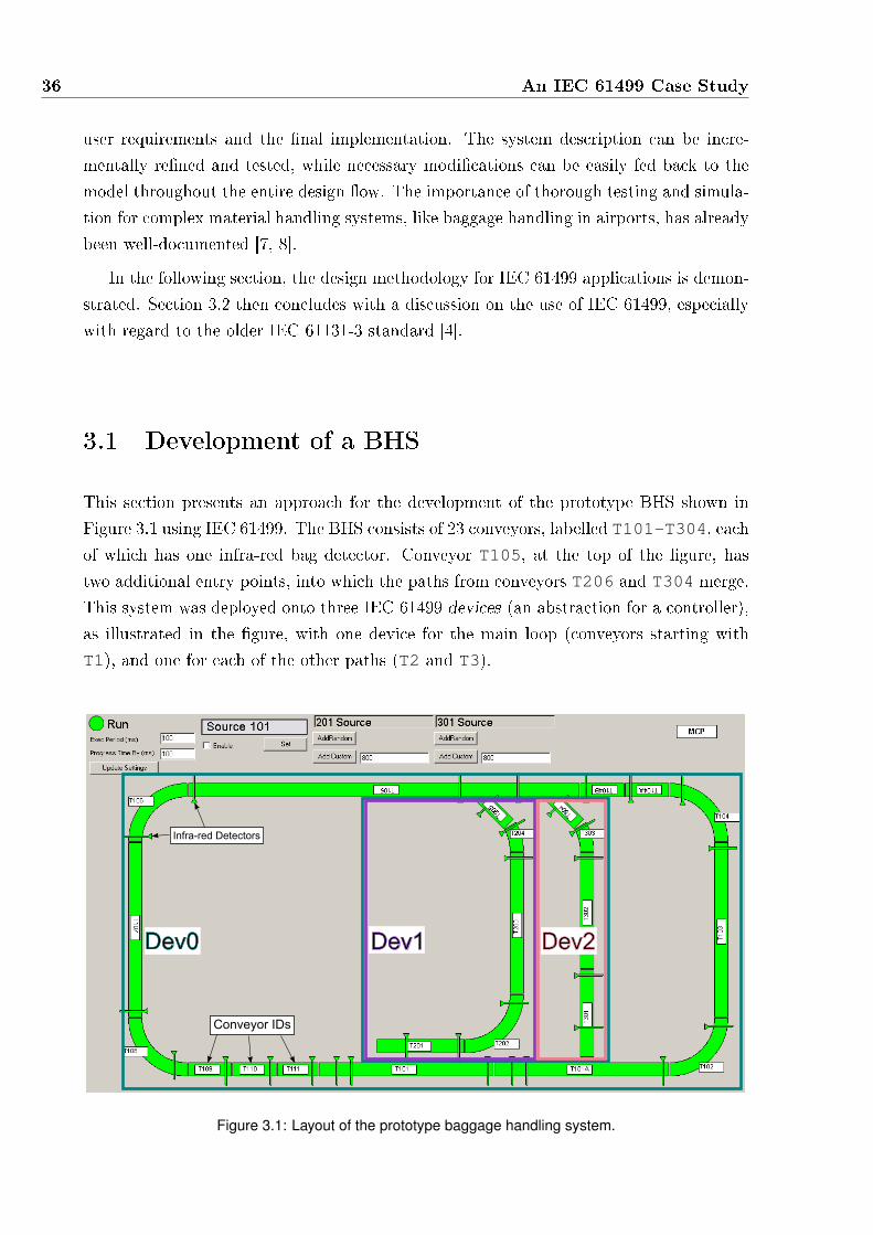
36 An IEC 61499 Case Study
user requirements and the �nal implementation. The system description can be incre-
mentally re�ned and tested, while necessary modi�cations can be easily fed back to the
model throughout the entire design �ow. The importance of thorough testing and simula-
tion for complex material handling systems, like baggage handling in airports, has already
been well-documented [7, 8].
In the following section, the design methodology for IEC 61499 applications is demon-
strated. Section 3.2 then concludes with a discussion on the use of IEC 61499, especially
with regard to the older IEC 61131-3 standard [4].
3.1 Development of a BHS
This section presents an approach for the development of the prototype BHS shown in
Figure 3.1 using IEC 61499. The BHS consists of 23 conveyors, labelled T101-T304, each
of which has one infra-red bag detector. Conveyor T105, at the top of the �gure, has
two additional entry points, into which the paths from conveyors T206 and T304 merge.
This system was deployed onto three IEC 61499 devices (an abstraction for a controller),
as illustrated in the �gure, with one device for the main loop (conveyors starting with
T1), and one for each of the other paths (T2 and T3).
Dev1 Dev2Dev0
Conveyor IDs
Infra-red Detectors
Figure 3.1: Layout of the prototype baggage handling system.

3.1 Development of a BHS 37
3.1.1 Model-View-Controller Design
Instead of just developing the controller for a component, IEC 61499 is also suitable
for the Model-View-Controller design pattern [74]. In this approach, three elements are
de�ned for each component, illustrated in Figure 3.2. The model, sometimes referred to
as the plant, simulates the physical aspects of the component, including sensor data and
actuator motion. The controller controls the model to implement the required behaviour.
The visualisation presents a visual representation of the component, optionally also in-
cluding a graphical interface to allow a human-machine interface to the controller. The
set of elements for a component are connected together, where each element provides and
receives data with the other elements. This approach allows the closed-loop testing of the
controller together with a model of the actual component. The visualisation is used to
provide the developer or user with a detailed view of the system at run-time.
Model
View
Controller
Figure 3.2: Illustration of Model-View-Controller Design.
3.1.2 A Conveyor Section
Figure 3.3 shows a sub-section of a baggage handling system, where a single conveyor
section is comprised of a motor for the belt, sensors and optionally merge or divert points.
As the motor moves the belt forwards or backwards, the movement of the belt is measured
by a rotary encoder (not pictured), allowing a controller to measure the movement and
speed of the belt. To detect bag positions, there is at least one infra-red bag detector or
photo-eye on each conveyor section. Photo-eyes provide a binary input to the controller
indicating whether or not a bag is present at a particular position.
The arrows at the bottom of the �gure indicate the sources of bags, which follow the
green or blue conveyor paths. At the merge point, which is part of the large conveyor on
the right, the two paths combine into a single path. A conveyor may also have a diverter,
which is able to push bags from the middle of one conveyor section onto the start of

38 An IEC 61499 Case Study
Conveyor Belt
Photo-eye
Merge Point
Belt Motor
Bag Flow
Bag Flow
Figure 3.3: Components of a conveyor.
another. Using diverters, the controller must route bags in such a way that each bag gets
to its required destination.
In the following subsections the development of the model and controller for a generic
conveyor section will be described. Issues in the speci�cation of certain behaviours are
also identi�ed to motivate the extensions to IEC 61499 presented in Chapter 4.
Plant Model
The plant model mimics the actual conveyor by modelling the movement of bags on
the belt and the action of any diverters. It also simulates two sets of data: a rotary
sensor monitoring belt movement and infra-red bag detectors at various positions along
the conveyor.
The interface for the Conveyor_Model function block is shown in Figure. 3.4. The
interface separates event and data ports to the upper and lower sections of the block
respectively. Data ports must be associated with at least one event, as the internal
(bu�ered) copy of the variable is only updated when an associated event is present. These
associations are illustrated with vertical lines between the ports.
Conveyor_Model is a composite function block, which contains the function block
network shown in Figure 3.5. This network contains the embedded basic function blocks:
Conveyor_Belt_Model and Conveyor_Photoeyes_Model, which simulate the two
sets of data required to form the conveyor model. Conveyor_Belt_Model simu-
lates the rotary encoder by modelling the movement of the belt including acceleration

3.1 Development of a BHS 39
Figure 3.4: Interface for the Conveyor Model Composite Block.
and deceleration. The measurement of belt movement, relative to its start-up posi-
tion, is passed to the Conveyor_Photoeyes_Model function block through the con-
nection between the EncCount data port on each block. Using this position data,
Conveyor_Photoeyes_Model maintains a representation of the bags on the conveyor
and simulates the photo-eye detectors.
Belt Model Photoeye Model
Figure 3.5: Network of function blocks which model a conveyor section.

40 An IEC 61499 Case Study
In IEC 61499, function blocks are only activated once an input event is present. Dur-
ing execution, events and data that are received at the interface of the composite block
are passed to the connected ports in the network. Blocks which receive an input event are
activated, then they are executed, possibly emitting their own events. The connections
between function blocks in a network dictate the propagation of events and thus the activ-
ation order of blocks. For example, when the Tick event is received at the interface to the
Conveyor_Model block, the connection to Belt Model's TICK input event activates
the block. Then, when Belt Model emits the CNF output event the Photoeye Model
function block is activated. After the blocks �nish their execution, they are deactivated
until another connected input event is present at the interface of Conveyor_Model.
As the plant models physical behaviour, the function blocks need an input to identify
the passage of time. This can be achieved in two ways: (1) an event can be used to
indicate the passage of a pre-con�gured amount of time, or (2) an input data port can
de�ne the quantity of time passed since the last execution.
In the function block network, the input event TICK is shown on the interface of both
blocks. The input msSinceMidnight is used by Conveyor_Belt_Model to de�ne
how much time has passed between TICK events. For every TICK event, the distance
travelled by the belt is re-calculated using the simulated speed. The rotary encoder is
simulated by toggling the EncoderState output between 0 and 1 every time the belt
moves 5cm.
The Conveyor_Photoeyes_Model does not include the msSinceMidnight in-
put, as its behaviour is only dependent on the position of the belt and not on the passage
of time. The infra-red detectors require an array of all the bag positions on the conveyor
to determine if they intersect with the position of any attached detectors. Bag data is
therefore passed between conveyor sections as they exit the downstream end or when they
intersect an activated diverter.
Both the Conveyor_Belt_Model and the Conveyor_Photoeyes_Model blocks
are basic function blocks. While the behaviour of composite function blocks is de�ned
by a network of embedded blocks and their inter-connections, the behaviour of a basic
function block is de�ned by its execution control chart (ECC).
Figure 3.6 shows the ECC for the Conveyor_Belt_Model function block, which
consists of EC (execution control) states, EC transitions, and EC actions. By convention,
the initial state of an ECC is represented with a bold or double outline. A state can
optionally be associated with a set of actions, which may consist of an algorithm and/or
output event to be emitted at the completion of the algorithm. Each algorithm can be
described using any of a range of languages, including IEC 61131-3 languages [4], Java,
C or C++. As an ECC is a Moore-machine, the actions associated with a given state are
executed once on entry to the state. The priorities of transitions are labelled above the
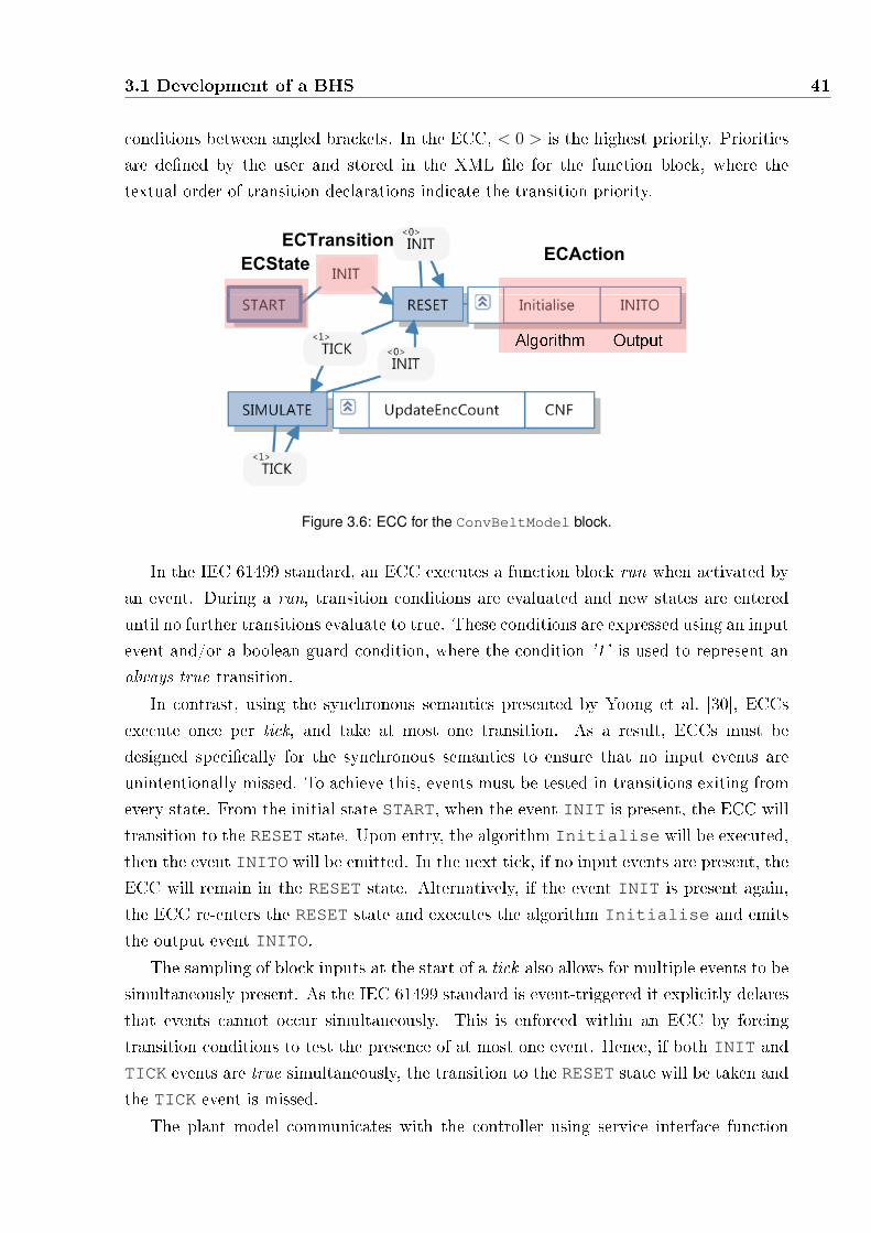
3.1 Development of a BHS 41
conditions between angled brackets. In the ECC, < 0 > is the highest priority. Priorities
are de�ned by the user and stored in the XML �le for the function block, where the
textual order of transition declarations indicate the transition priority.
ECTransition
ECStateECAction
Figure 3.6: ECC for the ConvBeltModel block.
In the IEC 61499 standard, an ECC executes a function block run when activated by
an event. During a run, transition conditions are evaluated and new states are entered
until no further transitions evaluate to true. These conditions are expressed using an input
event and/or a boolean guard condition, where the condition '1' is used to represent an
always true transition.
In contrast, using the synchronous semantics presented by Yoong et al. [30], ECCs
execute once per tick, and take at most one transition. As a result, ECCs must be
designed speci�cally for the synchronous semantics to ensure that no input events are
unintentionally missed. To achieve this, events must be tested in transitions exiting from
every state. From the initial state START, when the event INIT is present, the ECC will
transition to the RESET state. Upon entry, the algorithm Initialise will be executed,
then the event INITO will be emitted. In the next tick, if no input events are present, the
ECC will remain in the RESET state. Alternatively, if the event INIT is present again,
the ECC re-enters the RESET state and executes the algorithm Initialise and emits
the output event INITO.
The sampling of block inputs at the start of a tick also allows for multiple events to be
simultaneously present. As the IEC 61499 standard is event-triggered it explicitly delares
that events cannot occur simultaneously. This is enforced within an ECC by forcing
transition conditions to test the presence of at most one event. Hence, if both INIT and
TICK events are true simultaneously, the transition to the RESET state will be taken and
the TICK event is missed.
The plant model communicates with the controller using service interface function
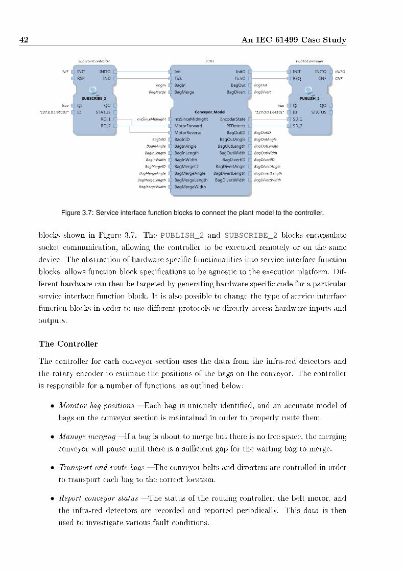
42 An IEC 61499 Case Study
Figure 3.7: Service interface function blocks to connect the plant model to the controller.
blocks shown in Figure 3.7. The PUBLISH_2 and SUBSCRIBE_2 blocks encapsulate
socket communication, allowing the controller to be executed remotely or on the same
device. The abstraction of hardware speci�c functionalities into service interface function
blocks, allows function block speci�cations to be agnostic to the execution platform. Dif-
ferent hardware can then be targeted by generating hardware speci�c code for a particular
service interface function block. It is also possible to change the type of service interface
function blocks in order to use di�erent protocols or directly access hardware inputs and
outputs.
The Controller
The controller for each conveyor section uses the data from the infra-red detectors and
the rotary encoder to estimate the positions of the bags on the conveyor. The controller
is responsible for a number of functions, as outlined below:
• Monitor bag positions � Each bag is uniquely identi�ed, and an accurate model of
bags on the conveyor section is maintained in order to properly route them.
• Manage merging � If a bag is about to merge but there is no free space, the merging
conveyor will pause until there is a su�cient gap for the waiting bag to merge.
• Transport and route bags � The conveyor belts and diverters are controlled in order
to transport each bag to the correct location.
• Report conveyor status � The status of the routing controller, the belt motor, and
the infra-red detectors are recorded and reported periodically. This data is then
used to investigate various fault conditions.
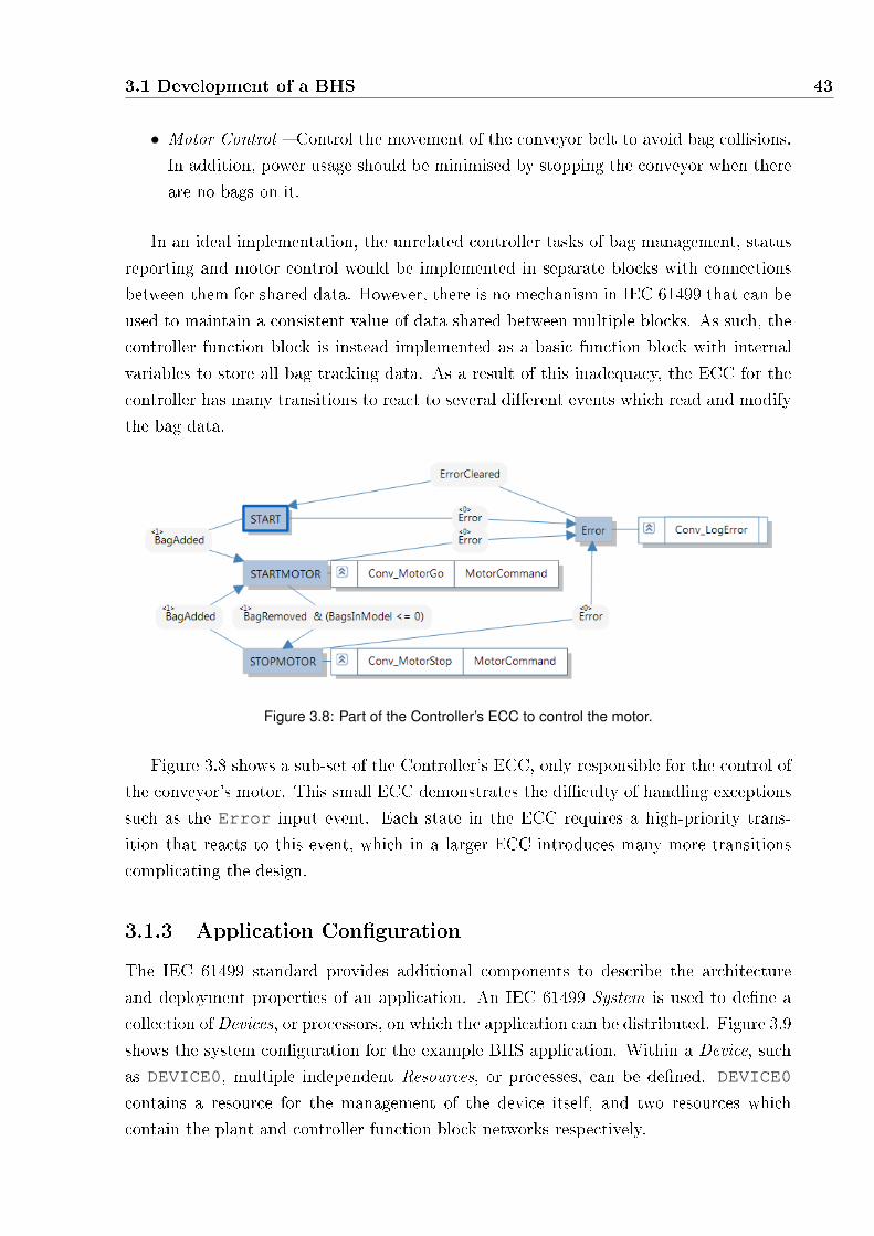
3.1 Development of a BHS 43
• Motor Control � Control the movement of the conveyor belt to avoid bag collisions.
In addition, power usage should be minimised by stopping the conveyor when there
are no bags on it.
In an ideal implementation, the unrelated controller tasks of bag management, status
reporting and motor control would be implemented in separate blocks with connections
between them for shared data. However, there is no mechanism in IEC 61499 that can be
used to maintain a consistent value of data shared between multiple blocks. As such, the
controller function block is instead implemented as a basic function block with internal
variables to store all bag tracking data. As a result of this inadequacy, the ECC for the
controller has many transitions to react to several di�erent events which read and modify
the bag data.
Figure 3.8: Part of the Controller’s ECC to control the motor.
Figure 3.8 shows a sub-set of the Controller's ECC, only responsible for the control of
the conveyor's motor. This small ECC demonstrates the di�culty of handling exceptions
such as the Error input event. Each state in the ECC requires a high-priority trans-
ition that reacts to this event, which in a larger ECC introduces many more transitions
complicating the design.
3.1.3 Application Con�guration
The IEC 61499 standard provides additional components to describe the architecture
and deployment properties of an application. An IEC 61499 System is used to de�ne a
collection of Devices, or processors, on which the application can be distributed. Figure 3.9
shows the system con�guration for the example BHS application. Within a Device, such
as DEVICE0, multiple independent Resources, or processes, can be de�ned. DEVICE0
contains a resource for the management of the device itself, and two resources which
contain the plant and controller function block networks respectively.

44 An IEC 61499 Case Study
Figure 3.9: System Configuration for BHS.
Within a single plant resource, the conveyor models exchange bag information, as the
bags move from one conveyor to another. Similarly, in a controller resource, the conveyor
controllers constantly share a variety of status information with upstream and downstream
conveyors. For this example application, input and output data is exchanged between the
two resources using pairs of PUBLISH and SUBSCRIBE service interface function blocks.
PUBLISH and SUBSCRIBE blocks are also used to exchange data between the plant and
controller resources on two di�erent devices.
3.1.4 The Visualisation
The state of the simulated plant and controller can be visualised together by using a
separate application for domain speci�c visualisation. Using nxtStudio, a visualisation
can be developed for each component using a graphical editor with support for animations
and advanced features using C# to control the visual appearance. A canvas is then used
to graphically arrange the visual representation of each component to provide a complete
view of the system as shown in Figure 3.10. The visualisation can also aid human-
machine interaction by displaying graphical control panels, as shown at the top of the
�gure, allowing the user to interact with the simulated system.

3.2 Discussion 45
Figure 3.10: Screenshot of 2D BHS Visualisation created using nxtStudio [1]
3.2 Discussion
In the development of this case study, the advantages of IEC 61499 were utilised to
create a reusable library of distributable components. However, some aspects of the
resulting design were not ideal, such that other languages are able to produce more succint
descriptions of the same behaviour.
3.2.1 Advantages of IEC 61499
IEC 61499 o�ers signi�cant advantages over the traditional IEC 61131-3 approach. Func-
tion blocks can be used for model-driven engineering, improving the reuse of components
and enabling code synthesis for multiple deployment platforms. IEC 61499 is also able
to employ the model-view-controller design pattern and describe both the model and
the controller, allowing closed-loop testing prior to deployment. Visualisation of the sys-
tem further aids the designer by displaying complete system information and providing a
graphical interface for human-machine interaction. Visualisation also bene�ts debugging
of the controller prior to the construction of the physical system, and once the hardware
has been constructed, the same visualisation can be used to monitor the deployed system.
The graphical nature of the standard also simpli�es many aspects of a design. In
particular, ECC state-machines and the con�guration and connections of components in
a function block network are much simpler to design and understand than textual code.
IEC 61499 systems, devices and resources also allow developers to easily de�ne and modify
the distribution of an application. Tools are then used to simplify the deployment of an
application to multiple devices.

46 An IEC 61499 Case Study
3.2.2 De�ciencies
As noted in the design of the conveyor controller, it is not possible for multiple blocks in a
network to all read and write to the same variable. Instead, internal variables in a single
basic function were used, requiring the ECC to describe multiple behaviours. This usage
of a single ECC also demonstrated that ECCs are too simplistic to describe complex
behaviours, to the extent that the ECC for the controller block requires more states
and transitions than would be necessary using other state-machine languages, including
IEC 61131-3 SFCs. Further, as discussed in the previous chapter, ECCs have also been
shown to be ine�ective for describing exception handling behaviour, lacking hierarchy and
parallelism found in other state-machine languages.
The most signi�cant de�ciency of the standard is the ambiguous semantics which were
discussed in the previous chapter. As a result, function blocks developed using one tool
are likely to be ine�ective when executed with another tool. The synchronous semantics
for IEC 61499, developed by Yoong et al. [31], o�ers many bene�ts including superior
performance and determinism. Despite not being event-triggered, the semantics are com-
patible with the standard, allowing function blocks developed assuming event-triggered
semantics to also be executed. However, as with all variations in execution approaches,
the behaviours will diverge under certain scenarios. Importantly, ECCs can not be used
for reliable software development with a synchronous semantics, as simultaneous events
will always be missed. The following chapter seeks to address the identi�ed de�ciencies
by developing an extended synchronous semantics for IEC 61499.
4Hierarchical and Concurrent ECCs for
IEC 61499 Function Blocks
This chapter enhances basic function blocks by allowing explicit hierarchy and concurrency
within an IEC 61499 basic function block, similar to Statecharts [27]. These extensions,
called Hierarchical and Concurrent ECCs (HCECCs), can be resolved into a fully IEC
61499 standard compliant form.
As discussed in section 3.2.2 of the previous chapter, the ECC Moore-machines con-
tained within basic function blocks are inadequate for the design of complex behaviours.
For example, the single control �ow described by an ECC complicates the modelling of
concurrent behaviours. In addition, ECCs do not allow users to separate high-level beha-
viour such as initialisation and error handling. As a result, more states and transitions
are required to describe the same behaviour compared to other graphical state-machines.
Existing formalisms, such as Statecharts provide the ability to embed hierarchy and
concurrency within a single state-machine. However, they cannot be used as a replacement
for ECCs as their semantics are incompatible with the IEC 61499 standard. For example,
Statecharts is essentially a control �ow language while IEC 61499 requires an integration
of control and data �ow. Also, IEC 61499 has a restriction that does not allow transitions
to test more than one input event at any time.
HCECCs introduce some syntactic sugar in the form of two operators, (parallel and
re�nement) which enable a Statecharts-like state-machine to be embedded within a
47

48 Hierarchical and Concurrent ECCs for IEC 61499 Function Blocks
single basic function block. Each of these operators can be resolved to an IEC 61499
standard composite function block executing using a synchronous semantics. As shown
later in Chapter 5, HCECCs can be used to model real-life applications. Also, Chapter 6
shows how e�cient and standard-compliant code can be generated from HCECCs.
The main contributions of this chapter are:
1. A formalism for IEC 61499 function blocks and their execution using synchronous
semantics.
2. The development of the HCECC framework using the parallel and re�nement oper-
ators.
3. A denotational synchronous semantics of IEC 61499 function blocks that maps
HCECCs to a standards-compliant representation.
This chapter is organized as follows. Section 4.1 presents a formalism for IEC 61499
and a description of the semantics for basic and composite function blocks. The proposed
hierarchical and concurrent extension to ECCs (HCECCs) is introduced in section 4.2.
The two operators used by an HCECC are presented in sections 4.2.1 and 4.2.2. Sec-
tion 4.3 discusses the semantics of HCECCs by comparing them with other graphical
state-machines. Finally, section 4.4 concludes with a summary of the features, limitations
and advantages of HCECCs.
4.1 Formalisation of IEC 61499
This section presents a formal model for IEC 61499 function blocks (FBs). The fol-
lowing concepts and notations will be used frequently throughout the rest of this chapter:
• Totally ordered set : A set A is totally ordered i� for any two elements a, b ∈ A,
where a ̸= b, a <A b or b <A a where <A is the antisymmetric and transitive
ordering relation for set A. The sub-script is omitted when the context is obvious
and unambiguous. The notation A = {a1, a2, . . . , an} is used to describe a totally
ordered set containing n elements where for all i, j ∈ [1, n], if i < j, then ai <A aj.
• Totally ordered union: If A and B are totally ordered and non-intersecting sets,
then the totally ordered union C = A⊕B is de�ned as follows. Firstly, C contains
all elements of A and B. Also, for each element pair a1, a2 ∈ A, if a1 <A a2, then
a1 <C a2. For each element pair b1, b2 ∈ B, if b1 <B b2, then b1 <C b2. Furthermore,
for any two elements a ∈ A, and b ∈ B, a <C b. The totally ordered union therefore
represents a concatenation of set A followed by set B.

4.1 Formalisation of IEC 61499 49
4.1.1 Function Block Interfaces
Function blocks have well-de�ned interfaces containing input and output events and vari-
ables. Figure 4.1 shows the interface for the Conveyor_Model block presented previ-
ously in Figure 3.4 of Chapter 3, which encapsulates the complete behaviour of a conveyor
in a baggage handling system. As shown in Fig. 4.1, a function block interface is divided
into four parts: input events on the top left, output events on the top right, input variables
on the bottom left, and output variables on the bottom right. The IEC 61499 standard
requires that each input (output) variable to be associated with at least one input (out-
put) event, represented by vertical lines between events and data variables. For example,
the input variable MotorForward is associated with the input event Tick. These as-
sociations enforce an input variable to be sampled only when an associated input event
is present. (Events are either present of absent, where as variables have a concrete value
at any instance). When no associated event is present, the block must use a previously
sampled value for the variable. Similarly, the value of an output variable is updated only
when an associated event is emitted.
Output Event-Data
Associations
Input Event-Data
Associations
Input Events{ Output Events{
Output Variables{Input Variables{Figure 4.1: Interface for the Conveyor Model Composite Block.
Interfaces are common to both basic and composite function blocks in IEC 61499
systems. They are de�ned as follows.
De�nition 1 (Function Block Interface). A function block interface is a tuple I =
⟨EII , V
II , α
II , E
IO, V
IO , α
IO⟩ where EI
I , V II , EI
O, and V IO are �nite sets of input events,
input variables, output events and outputs variables respectively. αII ⊆ EI
I × V II and
αIO ⊆ EI
O × V IO are the sets of input and output associations. For every vI ∈ V I
I , there
must exist some (eI , vI) ∈ αII for some eI ∈ EI
I . Similarly, for every vO ∈ V IO , there must

50 Hierarchical and Concurrent ECCs for IEC 61499 Function Blocks
exist some (eO, vO) ∈ αIO for some eO ∈ EI
O.
The interface I of the Conveyor_Model block in Figure 4.1 contains the following:
• EII = {Init, Tick, BagIn, BagMerge}
• V II = {msSinceMidnight, MotorForward, MotorReverse, . . . }
• αII = {(Tick,msSinceMidnight), (Tick,MotorForward), (Tick,MotorReverse), . . . }
• EIO = {InitO, TickO, BagOut, BagDivert}
• V IO = {EncoderState, PEDetects, BagOutID, . . . BagDivertID, . . . }
• αIO = {(TickO,EncoderState), (TickO,PEDetects), . . . }
4.1.2 Basic Function Block
Basic function blocks contain a function block interface, as well as algorithms, internal
variables and an execution control chart (ECC). Figure 4.2 shows the interface for the
basic function block Conveyor_Photoeyes_Model. Algorithms are user de�ned func-
tions, described in any language suitable for data processing. They operate over the input
and output variables of the interface as well as the internal variables of the block. In-
ternal variables and algorithms are collectively referred to as local FB declarations. Local
declarations do not have a visual representation in IEC 61499. They are de�ned below.
Figure 4.2: Interface for the Conveyor Photoeyes Model Basic Function Block.

4.1 Formalisation of IEC 61499 51
De�nition 2 (Local FB Declarations). Given a FB interface I, local FB declarations
LI is a pair ⟨VL, AIL⟩, where V I
L and AIL are sets of internal variables and algorithms
respectively. Algorithms operate over internal variables V IL , as well as input and output
variables V II , and V I
O (of the interface I).
For the basic function block Conveyor_Photoeyes_Model in Figure 4.1, the local
declarations are LI = ⟨V IL , A
IL⟩ where:
• V IL = {BagModel, BagExited, BagDiverted}
• AIL =
{INIT, TICK, CheckDiverters, BagExited, BagDiverted, BagIn, BagMerge1}
Recall that in addition to an interface and local declarations, a basic function block
also contains an execution control chart (ECC). Figure 4.3 shows the execution control
chart for the Conveyor_Photoeyes_Model block. The ECC consists of a �nite set of
states, with an initial state, START, shown with a bold outline. Each state is associated
with a �nite sequence of actions, which are comprised of algorithm executions (from AIL)
and the emission of output events. For instance, state INIT is associated with a sequence
of actions that will execute the algorithm INIT and emit the INITO output event. This
sequence of actions is executed whenever state INIT is entered.
Figure 4.3: ECC which simulates the infra-red PhotoEye sensor.
A transition in an ECC consists of a source state, a condition consisting of an input
event and a boolean guard condition over variables and a destination state. For example,
in Figure 4.3, the source state START has a transition that requires the presence of the

52 Hierarchical and Concurrent ECCs for IEC 61499 Function Blocks
INIT input event and a true boolean condition to the destination state INIT. A trans-
ition triggers when the corresponding input event is present and the associated boolean
condition evaluates to true. The triggering input event and boolean condition are op-
tional, and may not be provided for a transition. Always-true transitions, shown with a
condition of 1 have no associated events or boolean guard conditions.
Transitions exiting a state are totally ordered based on transition priorities. This order
is shown in Figure 4.3, where the transition from IDLE to Tick is ordered �rst (labelled
with < 0 >), before other transitions out of state IDLE (labelled with < 1 >,< 2 > . . .).
This label is omitted if the state only has one exiting transition. As described later,
transition ordering ensures deterministic execution since only the highest priority enabled
transition is taken during execution.
Having discussed the various constituents of a basic function block, it is now de�ned
below.
De�nition 3 (Basic Function Block). A basic function block, BFB, is a tuple
⟨I, LI ,ECCI,LI⟩ where I is a FB interface, LI = ⟨V IL , A
IL⟩ are the local declarations for
the block and ECCI,LIis a tuple ⟨S, s0 , λ, T ⟩. Here, S is a �nite set of states with s0 ∈ S
being the initial state. The action function λ : S → (AIL ∪EI
O)∗, returns a �nite sequence
of algorithms and/or outputs events (actions), that are executed and emitted for any state
s ∈ S. T : S → 2(EII ∪{1})×B(V̂ )×S, is the transition function, where 2(E
II ∪{1})×B(V̂ )×S is
restricted to contain only ordered sets, T (s) therefore, is a totally ordered set for any state
s ∈ S. V̂ refers to the set of all possible valuations of internal, input and output variables,
and B(V̂ ) refers to all boolean expressions over such valuations.
A transition t ∈ T (s) is described as (e, b, s′), where e is either an input event, or 1
(no triggering event). b is a boolean expression that can be evaluated to be true or false
based on the values of internal, input and output variables of the FB. The transition t
is said to be enabled when e is present (or is equal to 1), and b evaluates to true. Any
transitions that use the always-true event (1) with a true boolean condition is always
enabled. If t is enabled, the ECC moves from being in state s to s′ and the actions λ(s′)
are executed. The short-hand se,b−→ s′ is interchangeably used instead of (e, b, s′) ∈ T (s).
Note that the set of transitions for every state in the ECC of the basic function block
is totally ordered. As we discuss later, our execution semantics restrict ECC execution to
always take the highest-priority enabled transition, resulting in deterministic execution.
For the ECC ECCI,LI= ⟨S, s0 , λ, T ⟩ shown in Figure 4.3:
• S = {START, INIT, IDLE, TICK,
BagIn, BagExited, BagMerge, BagDiverted}
• s0 = START
4.1 Formalisation of IEC 61499 53
• For the state BagExited of the ECC:
� λ(BagExited) = {BagExited,BagOut}.
� T (BagExited) = {(1, BagDiverted,BagDiverted),
(1, true,IDLE)}, which is an ordered set.
Using the short-hand stated earlier, these transitions can be rewritten as:
BagExited1,BagDiverted−−−−−−−−→ BagDiverted and
BagExited1−→ IDLE.
Since T (BagExited) is an ordered set, the �rst transition to BagDiverted
has a higher priority than the second transition to state to IDLE.
Execution Semantics of Basic Function Blocks
The synchronous execution of IEC 61499, separates execution into individual steps known
as ticks.
The synchronous execution of a basic function block involves the following steps in
every tick:
1. All event inputs (EII ) are sampled at the beginning of the tick. An input variable (in
V II ) is sampled only if an associated input event is present (as per the associations
contained in αII ).
2. From the current state s in the ECC of the function block, the trigger conditions of
transitions in T (s) are evaluated in order. The �rst enabled transition (for which
the related input event is present and the boolean condition evaluates to true), is
taken and a new state is entered. However, if no transitions are enabled, the ECC
remains in the current state, and execution for the current tick completes.
3. When a destination state s′ is entered after a transition, algorithms and events in
its set of actions (λ(s′)) are executed and emitted sequentially in order.
4. At the end of the tick, output events emitted during step 3 are used to sample the
values of their associated output variables (according to associations contained in
αII ).
The ECC in Figure 4.3 is used to demonstrate the execution sequence of a basic
function block. Assuming that the ECC is in its initial state START, the execution takes
the following steps:
1. At the start of the tick, input events and any associated input variables are sampled.
2. The transitions of START are evaluated in order. Since there is only one transition
to state Init, it is checked whether it can be enabled.

54 Hierarchical and Concurrent ECCs for IEC 61499 Function Blocks
3. If the Init event (the trigger input for the above transition) is present, the ECC
takes the transition to the INIT state. The actions of the state Init, the algorithm
INIT and the output event INITO, are executed and emitted respectively.
4. Any interface output variables associated with the emitted output INIT0 are up-
dated.
5. The tick ends, and the same sequence is repeated in the next tick (with state INIT
being the current state in the next tick).
Observation 1 (Determinism of Basic Function Blocks). A BFB BFB = ⟨I, LI ,ECCI,LI⟩is deterministic.
The interface for any function block, including basic function blocks, is deterministic
because given the same input events and variables, the sampling of inputs (step 1 of the
semantics) is always the same. Similarly, given the same output events and variables,
the sampling of outputs (step 4 of the semantics) is always the same. Intuitively, the
execution of an ECC is deterministic because of the explicit ordering of transitions. Even
if two transitions can be enabled in a tick, only the highest priority transition is taken,
(steps 2 and 3) .
4.1.3 Composite Function Block
A composite function block (CFB) contains an interface and a �nite network of connected
function block instances.
A function block instance, fb = ⟨name, FBT ⟩, has a unique identi�er or name, and
instantiates some basic or composite function block (FBT ). The set of function block
instances in the function block network in a CFB are contained in a totally ordered set,
and as discussed later, this order is vital for the deterministic execution of the composite
function block.
Figure 4.4 shows the function block network embedded within the Conveyor_Model
block. This example contains two instances, in order:
• BeltModel, an instance of the Conveyor_Belt_Model basic function block.
• PhotoeyeModel, an instance of the Conveyor_Photoeyes_Model basic func-
tion block.
Note that when referring to the input or output events and variables of a FB instance,
the notation <instance name>.<event/variable name> is used. For example,
the output variable PEDetects of instance BeltModel is written:
BeltModel.PEDetects. Input or output events and variables of the interface of the

4.1 Formalisation of IEC 61499 55
Figure 4.4: Network of blocks within the Conveyor Model composite function block.
CFB are referred to directly by the name of the event or variable. For example, InitO
refers to the output event InitO of the CFB.
Each FB instance in a function block network may be connected through event and
data connections to the interface of the CFB and/or to other FB instances in the network.
The connections allow the exchange of information between FB instances and the interface
of the CFB. The notation src 7→ dest is used to describe a connection from a source (event
or variable) src to a destination dest. A connection src 7→ dest can be written as a pair
(src, dest) for brevity.
There are three types of event connections in a function block network:
• CEI2I : From an input event of the block's interface to an input event of a FB
instance contained in the block, such as Tick 7→ BeltModel.TICK
• CEO2I : From an output event of a FB instance to an input event of another (or the
same) FB instance in the network. For example
BeltModel.CNF 7→ PhotoEyeModel.Tick. Connections from one instance to
an instance that is ordered earlier (such as the connection: PhotoEyeModel.Cnf
7→ BeltModel.Tick) are called feed-back connections by convention.
• CEO2O: From an output event of a FB instance to an output event of the block's
interface. For example PhotoEyeModel.Cnf 7→ TickO
Similarly, there are three types of data connections:

56 Hierarchical and Concurrent ECCs for IEC 61499 Function Blocks
• CV I2I : From an input variable of the interface to an input variable of a FB instance
in the network. For example Accel 7→ BeltModel.Accel.
• CV O2I : From an output variable of a FB instance to an input variable of another
(or the same) FB instance.
For example BeltModel.EncCount 7→ PhotoEyeModel.EncCount.
• CV O2O: From an output variable of a FB instance to an output variable of the
composite block, such as PhotoEyeModel.PEDetects 7→ PEDetects.
Only a single source variable can be connected to a destination variable in a CFB.
Further, variable connections are restricted such that only variables of the same type can
be connected together. Events have no such restriction, such that the input event TICK
of BeltModel can be connected to the input event Tick of the CFB and the output
event PhotoEyeModel.Cnf.
Having discussed the various constituents of a CFB, a formal de�nition is provided
below.
De�nition 4 (Composite Function Block). A composite function block CFB is a tuple
⟨I,FBNetworkI⟩ where I = ⟨EII , V
II , α
II , E
IO, V
IO , α
IO⟩ is a FB interface, and
FBNetworkI ⟨FBs, Cevents, Cvar⟩ is the FB network of the CFB, where
• FBs = {fb1,fb2, . . .fbn} is a �nite and totally ordered set of function block in-
stances of size n. Here each fbi is a FB instance ⟨namei, FBTi⟩, where FBTi is
either a basic or composite function block with interface
Ii = ⟨EIiI , V Ii
I , αIiI , E
IiO , V Ii
O , αIiO ⟩.
• The event connections set, Cevents, contains the connections.
Cevents = CEI2I ∪ CEO2I ∪ CEO2O where:
CEI2I ⊆ (EII )× (
n∪i=1
fbi.EIiI )
CEO2I ⊆ (n∪
i=1
fbi.EIiO )× (
n∪i=1
fbi.EIiI )
CEO2O ⊆ (n∪
i=1
fbi.EIiO )× (EI
O)
• The set of data connections, Cvar, contains the connections between variables.
Cvar = CV I2I ∪ CV O2I ∪ CV O2O where:
CV I2I ⊆ (V II )× (
n∪i=1
fbi.VIiI )
CV O2I ⊆ (n∪
i=1
fbi.VIiO )× (
n∪i=1
fbi.VIiI )
CV O2O ⊆ (n∪
i=1
fbi.VIiO )× (V I
O )

4.1 Formalisation of IEC 61499 57
Further, for any two distinct connections (src1, dest1), (src2, dest2) ∈ Cvar, dest1 ̸=dest2.
For the function block network within the Conveyor_Model CFB (Fig.4.4), FBs
contains the two instances in the following order:
• BeltModel of type Conveyor_Belt_Model
• PhotoeyeModel of type Conveyor_Photoeyes_Model
The set of event connections contains all connections to and from event ports in the
network, including:
• BeltModel.CNF 7→ PhotoEyeModel.Tick
• PhotoEyeModel.Cnf 7→ TickO
Similarly, the set of data connections contains all connections between data ports, for
example:
• Accel 7→ BeltModel.Accel
• BeltModel.EncCount 7→ PhotoEyeModel.EncCount.
Execution Semantics
The execution of a composite function block ⟨I,FBNetworkI⟩ (where FBNetworkI
= ⟨FBs, Cevents, Cvar⟩) is formalised in Algorithm 4.1. The execution of Algorithm 4.1
involves the following steps in every tick, which are illustrated using the function block
network within Conveyor_Model, shown in Figure 4.5:
1. As per section (A) of the algorithm (lines 3�5) and Figure 4.5, the inputs of the
composite function block interface are sampled at the start of the tick. Values of
input variables are updated if associated input events are present.
2. Section (B) of the algorithm (lines 6�25) executes each function block instance in
the network, in the order they appear in the set FBs. In Figure 4.5 the instances
have been drawn in order from left to right, showing that steps B1 and B2 of the
instance BeltModel execute before steps B1 and B2 of PhotoeyeModel. The
execution of each instance fbi involves the following steps:
(a) Step (B1) (lines 8�24) propagates connected inputs to the instance. In this
step, an input event of the interface of the executing instance is set to present
if any source event connected to it (through event connections) is present
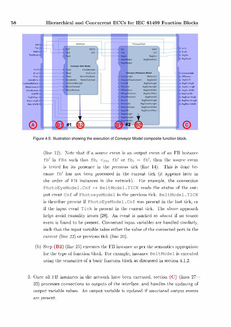
58 Hierarchical and Concurrent ECCs for IEC 61499 Function Blocks
Figure 4.5: Illustration showing the execution of Conveyor Model composite function block.
(line 12). Note that if a source event is an output event of an FB instance
fb′ in FBs such that fbi <FBs fb′ or fbi = fb′, then the source event
is tested for its presence in the previous tick (line 14). This is done be-
cause fb′ has not been processed in the current tick (it appears later in
the order of FB instances in the network). For example, the connection
PhotoEyeModel.Cnf 7→ BeltModel.TICK reads the status of the out-
put event Cnf of PhotoeyeModel in the previous tick. BeltModel.TICK
is therefore present if PhotoEyeModel.Cnf was present in the last tick, or
if the input event Tick is present in the current tick. The above approach
helps avoid causality issues [28]. An event is marked as absent if no source
event is found to be present. Connected input variables are handled similarly,
such that the input variable takes either the value of the connected port in the
current (line 22) or previous tick (line 20).
(b) Step (B2) (line 25) executes the FB instance as per the semantics appropriate
for the type of function block. For example, instance BeltModel is executed
using the semantics of a basic function block as discussed in section 4.1.2.
3. Once all FB instances in the network have been executed, section (C) (lines 27�
33) processes connections to outputs of the interface, and handles the updating of
output variable values. An output variable is updated if associated output events
are present.
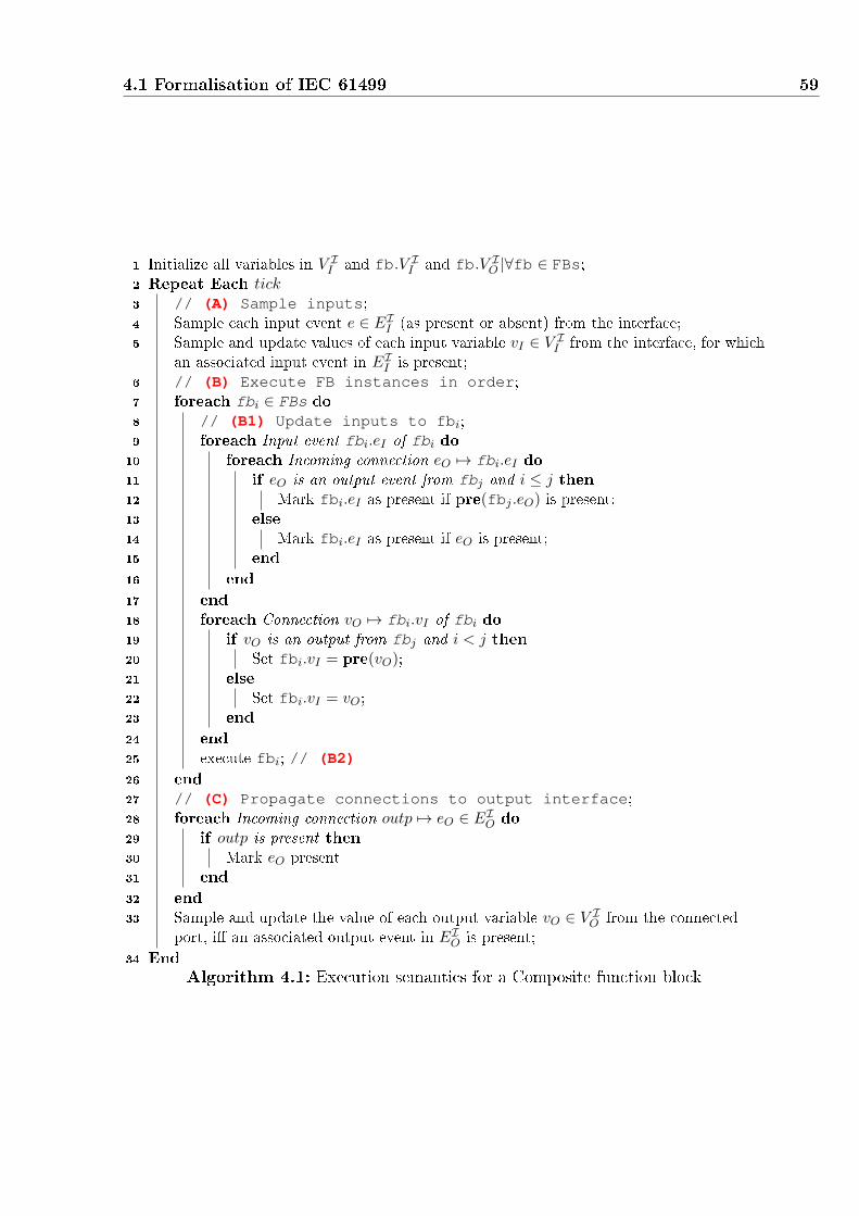
4.1 Formalisation of IEC 61499 59
1 Initialize all variables in V II and fb.V I
I and fb.V IO |∀fb ∈ FBs;
2 Repeat Each tick3 // (A) Sample inputs;4 Sample each input event e ∈ EI
I (as present or absent) from the interface;
5 Sample and update values of each input variable vI ∈ V II from the interface, for which
an associated input event in EII is present;
6 // (B) Execute FB instances in order;7 foreach fbi ∈ FBs do
8 // (B1) Update inputs to fbi;9 foreach Input event fbi.eI of fbi do10 foreach Incoming connection eO 7→ fbi.eI do11 if eO is an output event from fbj and i ≤ j then12 Mark fbi.eI as present if pre(fbj .eO) is present;13 else
14 Mark fbi.eI as present if eO is present;
15 end
16 end
17 end
18 foreach Connection vO 7→ fbi.vI of fbi do19 if vO is an output from fbj and i < j then20 Set fbi.vI = pre(vO);21 else
22 Set fbi.vI = vO;23 end
24 end
25 execute fbi; // (B2)26 end
27 // (C) Propagate connections to output interface;28 foreach Incoming connection outp 7→ eO ∈ EI
O do
29 if outp is present then
30 Mark eO present
31 end
32 end
33 Sample and update the value of each output variable vO ∈ V IO from the connected
port, i� an associated output event in EIO is present;
34 End
Algorithm 4.1: Execution semantics for a Composite function block

60 Hierarchical and Concurrent ECCs for IEC 61499 Function Blocks
As shown above, the execution of a CFB involves three parts in every tick: (A) the
sampling of interface inputs, (B) the execution of the contained FB instances, and (C)
the emission of interface outputs.
For any function block, including composite function blocks, interface events, variables
and their associations remain the same during every execution (every tick) of the CFB.
Hence, for step (A), given an environment providing the same input events and input
variable values during two di�erent ticks of execution, the input sampling will be carried
out in the same manner. Similarly, for step (C), if the function block instances inside the
CFB network produce the same output events and variables during two di�erent ticks of
execution, the output sampling (emission of outputs and modi�cation of output variable
values) will be identical.
Given the above, the only possible source of non-determinism in the processing of a
CFB could be step (B): the execution of the FB instances contained in the CFB network.
Recall that the FB instances in a CFB network are always executed in the same �xed
order every tick. Hence, the determinism of CFB execution depends on establishing that
the execution of every instance contained in the network is also deterministic. A CFB can
contain two types of FB instances: BFB instances or CFB instances. By observation, BFB
instances always execute deterministically (Obs. 1). On the other hand, a CFB instance
can be resolved into into a network of FB instances, resulting �nally into a network of
BFBs, executing in a �xed order every tick. Since the execution of every CFB can be
resolved into the �xed order execution of basic function block instances, and knowing that
BFBs execute deterministically, CFBs therefore also execute deterministically (Obs. 2).
Observation 2 (Determinism of Composite Function Blocks). The execution of composite
function block CFB = ⟨I,FBNetworkI⟩ is deterministic.
4.2 Hierarchical and Concurrent ECCs
HCECCs introduce two operators to enhance the modelling of IEC 61499 function blocks.
The operators are parallel and re�nement, which enable Statecharts-like [27] speci�c-
ations within basic function blocks. The parallel operator allows the description of in-
dependent or concurrent reactions by allowing multiple ECCs to execute concurrently
within a single basic function block. The re�nement operator allows a top-down beha-
vioural speci�cation, where a state in an ECC can be re�ned by one or more parallel
ECCs.
As an example, Figure 4.6 shows a reimplementation of the Conveyor_Model com-
posite block (shown earlier in Fig. 4.4), as a basic function block that uses the two HCECC
operators. There are two parallel ECCs, named BeltModel and InfraredModel.

4.2 Hierarchical and Concurrent ECCs 61
These parallel ECCs re�ne the state Running of the main ECC for the basic func-
tion block. Intuitively, whenever the ECC of the basic function block enters the state
Running, the two parallel ECCs start executing. These ECCs execute using the inputs
and outputs of the interface of the basic function block, and may also communicate with
each other using the internal variables of the basic function block. The parallel ECCs
are executed sequentially and in a �xed order once per tick, while the HCECC is in state
Running. The parallel execution is terminated when the ECC of the basic function block
takes the top-level transition out of state Running.
Refined State
ECC Name
Parallel ECCs
Figure 4.6: HCECC specification of the Conveyor Model
HCECCs allow arbitrary levels of nested re�nement and concurrency within a standard
function block interface. The semantics are compositional, following the approach presen-
ted by Argos [67], and despite the syntactic extensions, HCECCs remain compatible with
the IEC 61499 standard. This section shows how a multi-level HCECC is translated into
a standard composite function block. The process, illustrated in Figure 4.7, uses three
di�erent algorithms, built around the two operators.
The two operators are now presented, starting with the parallel operator in sec-
tion 4.2.1 and re�nement in section 4.2.2. Finally, the algorithm to �atten arbitrary
levels of nested re�nement and concurrency is presented in section 4.2.3.

62 Hierarchical and Concurrent ECCs for IEC 61499 Function Blocks
Algorithm: FlattenHCECC
Algorithm: RemoveRefinement
Algorithm: Par2CFB
Figure 4.7: Overview of HCECC translation
4.2.1 Parallel HCECCs
A parallel HCECC consists of an ordered set of ECCs that share a common interface and
local declarations (internal variables and algorithms). Parallel HCECCs can be translated
directly to an equivalent composite function block. Parallel ECCs can be used to describe
concurrent behaviours, separating independent reactions, but allowing communication
between them. In the presented synchronous semantics, they are especially useful as they
allow for the design of a state-machine that can react to multiple simultaneous events
using multiple ECCs.
It is de�ned as follows.
De�nition 5 (Parallel HCECC). A parallel HCECC HCECC∥ is a tuple ⟨I, LI ,ECCs⟩,where ECCs = {ECCI,LI
1 , . . . ,ECCI,LIn } is an ordered set of ECCs within an interface I,
and with local declarations LI.
Figure 4.8 shows a parallel HCECC HCECC∥ = ⟨I, LI ,ECCs⟩, where ECCs =
{ECC1,ECC2} contains two ECCs ECC1 and ECC2 that are logically parallel with a
synchronous execution semantics similar to Pret-C [75]. Each of these ECCs can access
the events and variables of the common interface. In addition, each ECC can also read and
modify internal variables and execute any algorithms contained in the local declarations
of the function block.

4.2 Hierarchical and Concurrent ECCs 63
Figure 4.8: A sample parallel HCECC
Execution semantics of Parallel HCECCs
The synchronous execution of a parallel HCECC involves the following steps in every tick:
1. Interface inputs are sampled, i.e. input events and associated input variables.
2. ECCs contained in ECCs are executed sequentially in order (in which they appear
in ECCs).
3. Finally, interface outputs (events and variables) are emitted and the tick completes.
Note that the �xed order execution of parallel ECCs mirrors the �xed order execu-
tion of function block instances within a CFB (section 4.1.3). This similarity is used to
map parallel HCECCs to CFBs in a straightforward manner. This mapping also allows
simultaneous events to be reacted to, with each ECC or FB instance reacting to a single
event.
Parallel ECCs communicate with each other directly, using variables, which can cause
ambiguities or non-determinism in the execution behaviour of a parallel HCECC. For
example, if an output variable of the common interface is written to by two ECCs in
a single tick, only one of these values can be actually emitted to the interface. In the
setting of HCECCs, any ambiguities in execution behaviour are avoided by de�ning a
semantics that ensures every parallel HCECC can be resolved into a composite function
block. Thus, each ECC is considered to be analogous to a FB instance in a CFB, executed
sequentially in the same �xed order. Communication between these FB instances must
therefore recreate the style of direct communication between each ECC. As such, variables
that can be written to by an ECC must be passed to the next FB instance that will be
executed, even if they are not modi�ed. From this communication, it is elementary to see
64 Hierarchical and Concurrent ECCs for IEC 61499 Function Blocks
that the last FB instance to execute (corresponding to the last ECC) must emit output
variables to the CFB interface. Output events are more easily handled with connections,
as the FB network can have a event connection from each FB instance to the output event
in the interface of the CFB.
Since composite function blocks execute deterministically (section 4.1.3)), parallel
HCECCs can therefore also be shown to always execute deterministically and unambigu-
ously. The transformation of parallel HCECC into an equivalent CFB is now formally
presented.
Parallel HCECC to CFB Conversion
Algorithm 4.2 is used to convert a parallel HCECC into a composite function block. The
connections and basic function block instances within the CFB are created to implement
the same behaviour as the sequentially executed ECCs with shared variables. Intuitively,
the algorithm performs the following actions:
1. The interface of the HCECC becomes the interface of the newly created composite
function block (line 13, Alg. 4.2).
2. A new basic function block instance is created for each parallel ECC in the HCECC
(lines 3�6, Alg. 4.2).
3. All newly created basic function block instances are connected in a function block
network so that each FB instance can exchange information (using events and vari-
ables) with the main interface as well as the other function block instances (lines
7�10, Alg. 4.2).
The details of the above steps are illustrated by showing how the composite function
block network in Figure 4.9 is obtained from the parallel HCECC shown in Figure 4.8.
Algorithm 4.2 calls algorithm CreateBFB (Alg. 4.3) for each parallel ECC in the
HCECC (line 4). CreateBFB (explained in detail later) converts each ECC ECCI,LI=
⟨S, s0 , λ, T ⟩ contained in the parallel HCECC into an instance fb of a newly created basic
function block. Importantly, the interface of each instance is similar to the interface of
the parallel HCECC, but additional inputs and outputs have been added to propagate
internal and output variables between instances.
After the creation of a FB instance for every parallel ECC, Alg. 4.2 creates the
connections between these instances using algorithms CreateEConns (Alg. 4.4) and
CreateVConns (Alg. 4.5) (both explained later), on lines 8 and 10. The connections
allow each FB to access the same information (events and variables) that were available
to the corresponding ECC in the parallel HCECC. The function block network is created

4.2 Hierarchical and Concurrent ECCs 65
Input: Parallel HCECC ⟨I, LI ,ECCs⟩Output: CFB CFB
1 //Create BFBs;2 Ordered set FBs = ∅;3 for each ECC ∈ ECCs do4 fb = CreateBFB(ECC, I, LI);5 FBs = FBs⊕ {fb};6 end7 //Create event connections;8 Set of event connections Cevents = CreateEConns(FBs, I);9 //Create variable connections;10 Set of variable connections Cvar = CreateVConns(FBs, I, LI);11 //Create CFB;12 FBNetworkI = ⟨FBs, Cevents, Cvar⟩;13 CFB = ⟨I,FBNetworkI⟩;14 return CFB;Algorithm 4.2: Algorithm Par2CFB. Resolves a parallel HCECC into a compositefunction block
Figure 4.9: Parallel ECCs flattened to a function block network
using these instances and sets of connections (line 12). Finally, the CFB is created using
this new FB network and the same interface as the parallel HCECC (line 13).
Fig. 4.9 shows how the instances in the CFB are connected. Intuitively, the events
(inputs and outputs) of the main interface I connect to corresponding events of the in-
terface of each of the FB instances. For example: A 7→ ParallelECC1.A and
ParallelECC2.Z 7→ Z. All FB instances read the input variables of the CFB inter-
face. As only one output variable can be connected to each output variable of the CFB
interface, only the last FB instance in FBs (according to the order of the set of ECCs
in the original HCECC) is connected. Moreover, internal and output variables of the

66 Hierarchical and Concurrent ECCs for IEC 61499 Function Blocks
original HCECC are propagated between instances by connecting the output version of
these variables from each FB instance to the corresponding input version of the FB in-
stance that will be executed next. For example connections: ParallelECC1.Output 7→ParallelECC2.Output and ParallelECC2.Output 7→ ParallelECC1.Output as
shown in Fig. 4.9. An event connection, such as ParallelECC1.PARO 7→ParallelECC2.PARI and ParallelECC2.PARO 7→ ParallelECC1.PARI is used
to force each FB instance to re-sample the connected internal and output variables in each
tick. This enables subsequent FBs to read the latest variable values during execution, and
the �rst FB instance will read the values emitted by the last FB instance at the end of
the previous tick.
Algorithm CreateBFB (Alg. 4.3), which creates a new basic function block and FB
instance from a parallel ECC, is now discussed in detail. First, an interface I ′ is created
for the new BFB BFB′ (lines 1�6). I ′ has the same input and output events as the interface
I of the parallel ECC (allowing it to read/write all input and output events of I) as wellas a new input event PARI and output event PARO (line 2) (more details appear later).
I ′ also has the same input and output variables, but it also contains: an input copy of
each internal or output variable and an output copy of each output variable (line 3). Note
that the input and output associations of I ′ preserve the associations between events and
variables of the original HCECC interface I (line 5), as shown in Fig. 4.9 (the associations
are shown explicitly within the CFB to aid readability).
The two additional events (PARI and PARO) are used to force sampling of interface
variables at the start and end of a execution respectively. PARI is associated with the
input copies of internal and output variables (line 5). Similarly, PARO is associated with
the output copies of internal and output variables (line 5). The communication between
the original parallel ECCs is recreated between FB instances by forcing PARO to be
emitted in each tick (by modifying the ECC as described later), and connecting PARO
(and associated variables) to PARI (and associated variables) of the instance that will
execute next. Thus, in each tick, each instance samples the internal and output variables
at the start of its execution and transfers the variables to the interface of the next instance.
The interfaces for each FB instance can be seen in Figure 4.9, where each new basic
function block has the same interface. Instances and BFBs are named based on the name
of the ECC in the parallel HCECC in Fig. 4.8. For example, instance ParallelECC1 of
a new BFB ParallelEg3_ParallelECC1 in Fig. 4.9 corresponds to the ECC ECC1
in Fig. 4.8. The input and output events of the original interface (Fig. 4.8) (A,B and Y, Z
respectively) remain, as well as the additional input and output events PARI and PARO.
The interfaces have input variables corresponding to all input, internal (Internal1 and
Internal2) and output variables (Output) of the original HCECC. In addition, the inter-
faces have output variables correspond to all local variables (Internal1 and Internal2)

4.2 Hierarchical and Concurrent ECCs 67
Input: FB interface I = ⟨EII , V
II , αI
I , EIO, V
IO , αI
O⟩, Locals LI = ⟨VL, AIL⟩, ECC
ECCI,LI= ⟨S, s0 , λ, T ⟩
Output: BFB instance fb1 //Create interface;2 Set EI = EI
I ∪ {PARI}; Set EO = EIO ∪ {PARO};
3 Set VI = V II ∪ VL ∪ V I
O ; Set VO = VL ∪ V IO ;
4 // Maintain original associations, adding: PARI associated withinput copies of internal and output variables, and PAROassociated with all output variables;
5 αI = αII ∪ {(PARI, vI)|vI ∈ VL ∪ V I
O }; αO = αIO ∪ {(PARO, vO)|vO ∈ VO};
6 I ′ = ⟨EI , VI , αI , EO, VO, αO⟩;7 //Create locals;
8 LI′= ⟨∅, AI
L ∪ {UpdateOutputs}⟩;9 //Create ECC;10 Set S′ = S;11 Set s′0 = s0 ;12 Create empty action function λ′ and transition function T ′;13 for each s ∈ S do
14 // Make each state execute UpdateOutputs and emit PARO;15 λ′(s) = λ(s)⊕ {UpdateOutputs, PARO};16 for each transition t = s
e,b−→ s1 in T do
17 T ′(s) = T (s)⊕ {t};18 end
19 //Loop states creation;
20 if there is no transition s1−→ s1 then
21 Mark sl = s; // Use sl to refer to s;22 if λ(s) is not empty then
23 Create new loop state sl; S′ = S′ ∪ {sl}; // Make sl refer to a new
state;24 λ′(sl) = {UpdateOutputs, PARO};25 for each transition t = s
e,b−→ s1 in T (s) do
26 T ′(sl) = T ′(sl) ∪ {sle,b−→ s1};
27 end
28 end
29 T ′(s) = T ′(s)⊕ {s 1−→ sl}; // Create a transition from s to sl(where sl refers to s or a new state);
30 end
31 end
32 Create ECC ECCI′,LI′
= ⟨S′, s′0 , λ′, T ′⟩;
33 Create Basic FB BFB′ = ⟨I ′, LI′,ECC′⟩;
34 Create FB instance fb = ⟨name,BFB′⟩ where name is a unique string;
35 return fb;Algorithm 4.3: Algorithm CreateBFB. Creation of BFB instance for a parallel ECC.

68 Hierarchical and Concurrent ECCs for IEC 61499 Function Blocks
and output variables (Output) of the original HCECC.
Next in Alg. 4.3, the local declarations LI′= ⟨V ′
L, AI′L ⟩ of BFB′ are created (line 8).
There are no internal variables in the new basic function blocks as the internal variables of
the parallel HCECC have been converted into input and output variables previously (on
line 3). AI′L contains all of the algorithms in the parallel HCECC (AI
L), as well as a new
algorithm UpdateOutputs1. UpdateOutputs is a simple algorithm that is used to update
the value of every output variable in I ′ after every tick. It is used to copy the input internal
and output variables to the corresponding output variables. Regardless of whether or not
ECCI,LImodi�es these internal or output variables, by executing UpdateOutputs at the
end of each tick the output copies of each variable are updated in order to be propagated
to other instances.
Finally, Alg. 4.3 creates the ECC ECCI′,LI′= ⟨S ′, s′0 , λ
′, T ′⟩ for BFB′ (lines 9�32). E.g.,
for the parallel HCECC shown in Fig. 4.8, Fig. 4.10 shows the original ECC ECC1 (Fig.
4.10(a)) and the corresponding ECC created by Alg. 4.3 (Fig. 4.10(b)). The algorithm
proceeds as follows. Initially, the set of states S ′ contains all states of the original ECC
ECCI′,LI′(line 10) and the initial state is set to be the initial state of ECCI′,LI′
(line 11).
Next, the action functions and transition functions λ′ and T ′ are initialized (line 12)
and populated using the for loop on lines 13�31. Here, each state s in the original ECC
ECCI′,LI′is processed as follows. Firstly, the action map λ′ for s is modi�ed to contain
the same sequence of algorithms and outputs as in λ (line 15). In addition, the execution
of the algorithm UpdateOutputs and the emission of the output PARO is appended to
this sequence (line 15). This is done to ensure that all output variables are updated
(by executing UpdateOutputs) by the new ECC whenever it executes. For example,
λ′(S1) = {Y, UpdateOutputs, PARO}. Also, s contains the same transitions in T ′ as in
the original ECC (lines 16�18).
In lines 19�30, the algorithm checks if a complementary loop state needs to be created
for s. A loop state is added to ensure that a transition is always enabled in the new ECC,
each added loop state is a copy of some original state but without the original action
map. This is because the new ECC must execute UpdateOutputs and emit PARO to
ensure that the values of the input variables are copied to corresponding output variables
at the end of each tick. If s has no always-true (or default) transition (line 20), then a
loop state is needed to handle the case where no existing transition may be taken in a
tick. If the action map of s (λ(s)) in the original ECC is not empty, then a new loop
state sl is created (line 24) and added to the set of states S ′. This loop state executes
UpdateOutputs and emit PARO whenever it is entered (line 24). The loop state sl has
the same transitions as s (lines 25�27). In case a loop state is not needed (s's action map
1UpdateOutputs contains assignments of the form vO = vI for every vO is an output variable of theinterface I ′ created from an interface output variable or an internal variable. vI is the matching inputvariable of the interface I ′ created from an interface output variable or an internal variable.

4.2 Hierarchical and Concurrent ECCs 69
was originally empty), then s itself becomes the loop state. Finally, s is modi�ed to have
an extra always-true transition to the loop state (line 29). For example, S1 1−→ S1_P as
in Fig. 4.10(b).
After all of the above computations are done, the new ECC is constructed on line 32
and the corresponding basic function block is created on line 33. Finally, a new instance
fb is created and returned by Alg. 4.3 in lines 34 and 35 respectively.
(a) Original ECC1 (b) ECC within ParallelEg3_ParallelECC1
Figure 4.10: Modification of Parallel ECCs
Algorithm 4.4 describes how event connections are created for the set of FB instances
FBs. Each FB instance fbi in this set is processed as follows. Firstly, input events of
the main interface I are connected to the corresponding input events of fbi (lines 6�
8). Similarly, output events of the main interface I are connected to the corresponding
output events of fbi (lines 10�12). Finally, for the output PARO of fbi is connected to
the input PARO of fbj, where j = i + 1 if fbi is not the last fb instance in FBs. If
fbi is the last fb instance in FBs, then fbj is the �rst instance in FBs. The connections
between PARO and PARI create a cycle of event connections from the �rst instance
to the last instance (and back) which allows the propagation of updated variable data
(as explained in the description of Alg. 4.5 later). For example, in Figure 4.9 PARO of
instance ParallelECC1 is connected to PARI of instance ParallelECC2 and PARO
of instance ParallelECC2 is connected to PARI of instance ParallelECC1.
Algorithm 4.5 describes how variable connections are created for the set of FB instances
(FBs). Each FB instance fbi in this set is processed as follows. Firstly, input variables of
the main interface I are connected to the corresponding input variables of fbi (lines 6�8).
Only the output variables of the last instance fbn are connected to the corresponding
output variables of the main interface I (lines 10�14). For example, Output of instance
ECC2 is connected to Output of the interface.

70 Hierarchical and Concurrent ECCs for IEC 61499 Function Blocks
Input: Ordered set of FB instances FBs, FB interface IOutput: Set of event connections Cefb
1 CeI2I = ∅; CeO2O = ∅; CePAR = ∅;2 n = |FBs|;3 for each i ∈ [1, n] do4 Select the i-th element fbi ∈ FBs;5 //input event connections;6 for each eI ∈ EI
I do
7 CeI2I = CeI2I ∪ {(eI 7→ fbi.eI)};8 end
9 //output event connections;10 for each eO ∈ EI
O do
11 CeO2O = CeO2O ∪ {(fbi.eO 7→ eO)};12 end
13 //PARI to PARO connection;14 if i < n then
15 fbj = fbi+1;
16 else
17 fbj = fb1;18 end
19 CePAR = CePAR ∪ {(fbi.PARO 7→ fbj .PARI)};20 end
21 return CeI2I ∪ CeO2O ∪ CePAR;Algorithm 4.4: Algorithm CreateEConns
Finally, the output variables of fbi, corresponding to the internal and output variables
of the original HCECC, are connected to the corresponding input variables of the next
instance fbj (lines 15�27). Here, where j = i + 1 if fbi is not the last fb instance
in FBs. If fbi is the last fb instance in FBs, then fbj = fb1 (the �rst instance in
FBs). For example, the Internal1 output of instance ParallelECC1 is connected to
in Internal1 input of instance ParallelECC2, and similarly the Internal1 output of
instance ParallelECC2 is connected to in Internal1 input of instance ParallelECC1.
Summary
Table 4.1 shows an overview of how two parallel ECCs in a parallel HCECC are executed
as an equivalent CFB. The input and output sampling of the interface (steps 1 and 6)
are the same for both implementations. Steps 2-5 show how each ECC or FB instance is
executed. The �rst ECC (ECC1) or FB instance (fb1) reads the current input values from
the interface. Internal and output variables are accessed directly by ECC1, but through
connections by fb1. In both cases, the values of the variables are as they were at the end
of the previous tick. ECC1 or fb1 is executed (step 3), where fb1 has the same behaviour
as ECC1 but will end by also emitting PARO and internal and output variables. The
second ECC (ECC2) or FB instance (fb2) executes similarly, except the values of internal
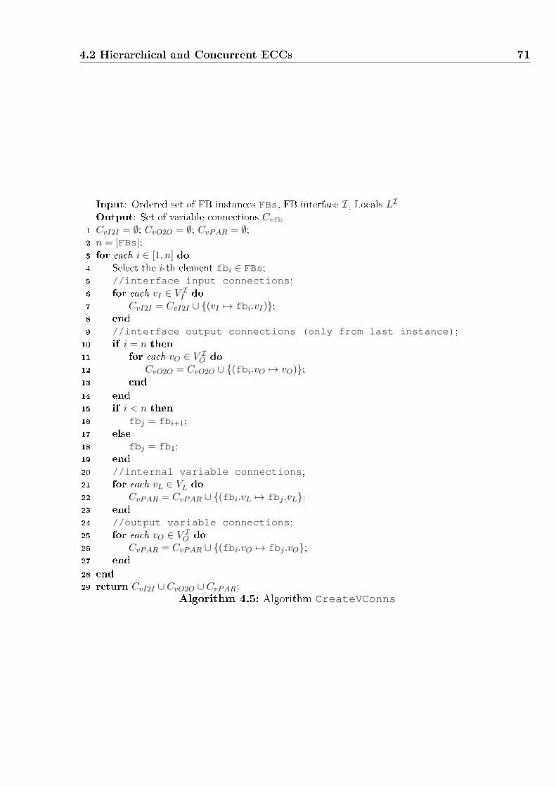
4.2 Hierarchical and Concurrent ECCs 71
Input: Ordered set of FB instances FBs, FB interface I, Locals LI
Output: Set of variable connections Cvfb
1 CvI2I = ∅; CvO2O = ∅; CvPAR = ∅;2 n = |FBs|;3 for each i ∈ [1, n] do4 Select the i-th element fbi ∈ FBs;5 //interface input connections;6 for each vI ∈ V I
I do
7 CvI2I = CvI2I ∪ {(vI 7→ fbi.vI)};8 end
9 //interface output connections (only from last instance);10 if i = n then
11 for each vO ∈ V IO do
12 CvO2O = CvO2O ∪ {(fbi.vO 7→ vO)};13 end
14 end
15 if i < n then
16 fbj = fbi+1;
17 else
18 fbj = fb1;19 end
20 //internal variable connections;21 for each vL ∈ VL do
22 CvPAR = CvPAR ∪ {(fbi.vL 7→ fbj .vL};23 end
24 //output variable connections;25 for each vO ∈ V I
O do
26 CvPAR = CvPAR ∪ {(fbi.vO 7→ fbj .vO};27 end
28 end
29 return CvI2I ∪ CvO2O ∪ CvPAR;Algorithm 4.5: Algorithm CreateVConns

72 Hierarchical and Concurrent ECCs for IEC 61499 Function Blocks
Execution Steps Parallel HCECC Equivalent CFB
1. Sample inputs of in-
terface.
1. Interface samples input
events and associated vari-
ables.
1. CFB interface samples in-
put events and associated vari-
ables.
2. Identify inputs for
�rst component.
2. The �rst ECC (ECC1) readsnew input events and variables
and directly reads internal and
output variables as they were
at the end of the previous tick.
2. The �rst BFB instance
(fb1) reads new input events
and variables and reads in-
ternal and output variables
connected from the second
BFB instance (fb2) as they
were at the end of the previous
tick.
3. Execute �rst com-
ponent, producing out-
puts.
3. ECC1 is executed, possibly
modifying internal and output
variables.
3. fb1 is executed, possibly
modifying internal and output
variables, and emits PAROand output copies of all in-
ternal and output variables.
4. Identify inputs for
second component.
4. The second ECC (ECC2)reads new input events and
variables and directly reads in-
ternal and output variables as
they were modi�ed by (ECC1).
4. The second BFB instance
(fb2) reads new input events
and variables and the latest
internal and output variables
connected from the �rst BFB
instance (fb1).5. Execute second com-
ponent, producing out-
puts.
5. ECC2 is executed, possibly
modifying internal and output
variables.
5. fb2 is executed, possibly
modifying internal and output
variables, and emits PAROand output copies of all in-
ternal and output variables.
6. Sample outputs at in-
terface.
6. Interface samples out-
put events and associated vari-
ables.
6. CFB interface samples out-
put events and associated vari-
ables.
Table 4.1: CFB Equivalence of Parallel HCECC semantics
and output variables have just been processed by ECC1 or fb1 respectively.

4.2 Hierarchical and Concurrent ECCs 73
The conversion of a parallel HCECC to a composite function block ensures that parallel
HCECCs are compliant to the IEC 61499 standard. The CFB transformation introduces
some execution overhead due to the additional interfaces that must be processed. In
addition, each ECC has additional states and transitions, noting that there is a linear
increase in the number of states and transitions. However, the manual design of a CFB
is more complicated than the equivalent parallel HCECC, and therefore more likely to
introduce bugs requiring more time to debug. The execution overhead is therefore minor
compared to the design-time simpli�cation a�orded by a parallel HCECC. In addition,
the execution overhead can be mitigated by directly compiling HCECCs for execution, as
shown in the compilers presented in chapter 6.
4.2.2 Re�ned HCECCs
Re�nement allows a set of one or more parallel re�ning ECCs to describe the behaviour
of a single state of an ECC. This introduces a notion of behavioural hierarchy within a
basic function block, that is present in other aspects of the IEC 61499 standard (such as
CFBs). Such hierarchy allows a high-level behavioural description to be re�ned, such that
within any of its states there can be further (re�ning) ECCs. A re�ned state in a re�ned
ECC in a function block is shown to be equivalent to a set of parallel ECCs, where the
�rst re�ned ECC communicates with the later re�ning ECCs to enable and disable their
behaviour. It is also possible for multiple states in an ECC to be re�ned in this way. A
de�nition for a re�ned HCECC follows.
De�nition 6 (Re�ned HCECC). HCECC◃ = ⟨I, LI ,ECCI,LI,ECCs, ◃⟩ is a
re�ned HCECC, where ECCI,LIis the re�ned ECC and ECCs = {ECCI,LI
1 , . . . ,ECCI,LIn }
is a set of n re�ning ECCs. ECCs is partitioned into m ordered and non-empty sets
PARTS = {ECCs1, . . . ,ECCsm}2 where 1 ≤ m ≤ max(|S|) (S is the set of states of
ECCI,LI). ◃ is the state-re�nement function that maps m states of ECCI,LI
to unique
partitions ECCsi of ECCs. If ◃(s) = ECCsi for some s ∈ S, then ECCsi ∈ ECCs is said
to re�ne state s.
Fig. 4.11 shows a re�ned HCECC HCECC◃ = ⟨I, LI ,ECCI,LI,ECCs, ◃⟩ where:
ECCs = {Para1,Para2}, PARTS = {{Para1,Para2}}, and ◃(RefinedState) =
{Para1,Para2}. This means that parallel ECCs Para1 and Para2 re�ne the behaviourof the state RefinedState in the main ECC. Note that each of the re�ning ECCs operate
using the events and variables of the HCECC (from the interface I and local declarations
LI).
2ECCs = ECCs1 ⊕ . . .⊕ ECCsm, and for all i, j ∈ [1,m], if i ̸= j then ECCsi ∩ ECCsj = ∅.

74 Hierarchical and Concurrent ECCs for IEC 61499 Function Blocks
Figure 4.11: HCECC with a state refined by two parallel ECCs
Execution of Re�ned HCECCs
A re�ned HCECC HCECC◃ = ⟨I, LI ,ECCI,LI,ECCs, ◃⟩ executes as follows:
1. Interface inputs are sampled, i.e. input events and associated input variables.
2. The re�ned ECC (ECCI,LI) is executed just as a standard ECC. If a transition is
taken out of a re�ned state s (for which ◃(s) is de�ned), the re�ning ECCs are not
executed in this tick, and stop being executed until s is re-entered. This results in
the pre-emption of the lower-level re�ning ECCs, due to a higher-level transition
being taken.
3. If the re�ned ECC is in a re�ned state s, the parallel ECCs in ◃(s) are executed in
a �xed order.
4. Finally, interface outputs (events and variables) are emitted and the tick completes.
A re�ned HCECC can be resolved into an equivalent parallel HCECC. As shown in
the previous section, parallel HCECCs are IEC 61499 standard-compliant since they can
always be resolved into composite function blocks. Hence, the conversion from a re�ned to
a parallel HCECC (and eventually to a composite function block) ensures that all re�ned
HCECCs are also standard-compliant. The transformation from a re�ned HCECC into
an equivalent parallel HCECC is now formally presented.
Re�nement to Parallel Conversion
Initially, to simplify discussion, an algorithm is presented that removes the re�nement from
a re�ned ECC assuming only one state is re�ned. Algorithm RefineToPar (Alg. 4.6)
creates a set of parallel ECCs with local declarations in which the re�ned ECC is executed
�rst, followed by the re�ning ECCs. The re�ned ECC is modi�ed to set a variable that will
enable and disable the behaviour of re�ning ECCs, making each re�ning ECC transition
to a Disabled state until re-enabled.

4.2 Hierarchical and Concurrent ECCs 75
Given a FB interface I, local declarations LI , a re�ned ECC ECCI,LI, a re�ned state s
in that ECC, and the re�ning ECCs ECCss, Alg. 4.6 returns the equivalent set of parallel
ECCs ECCs◃ and modi�ed local declarations LI◃ . For the example in Figure 4.11 the
algorithm produces the parallel ECCs shown in Figure 4.12.
Figure 4.12: Parallel ECCs equivalent to refinement in Figure 4.11
Lines 1�5 of Alg. 4.6 modify the local declarations, adding a new internal vari-
able (s◃_Disabled) on line 2 and two new algorithms on line 3. The new algorithms
(s◃_Enable, s◃_Disable) clear and set the s◃_Disabled variable respectively.
The �rst step in constructing the set ECCs◃ is to modify the main ECC (lines 8�
22). This involves adding the algorithm s◃_Enable to the actions of s◃ (line 13) so that
whenever state s◃ is reached, the variable s◃_Disabled is cleared (allowing the re�ning
ECCs to execute). Similarly, for every state s to which s◃ has an outgoing transition, the
respective action map is modi�ed to add the algorithm s◃_Disable (line 16). This ensures
that the variable s◃_Disabled is set when state s◃ is exited in the main ECC (forcing the
re�ning ECCs to stop executing). For example, for the parallel ECCs in Figure 4.12, the
action map of the �rst ECC has been changed to the following:
• λ0(Start) = {RefinedState_Disable}
• λ0(RefinedState) = {RefinedState_Enable,X}, where the emission of output
event X was part of the original re�ned HCECC.
The main ECC, modi�ed as above, is inserted into the set ECCs◃ as its �rst element
(line 23). This allows the execution of this ECC to enable and disable execution of the
re�ning ECCs.
Lines 24-43 modify each re�ning ECC (in ECCss), adding a new state (Disabled)
(line 26) that is used disable the standard behaviour of the ECC when the re�ned ECC is
not in state s◃. This new state can be seen in the ECCs in Figure 4.12 that were originally

76 Hierarchical and Concurrent ECCs for IEC 61499 Function Blocks
Input: I, LI = ⟨VL, AIL⟩,ECCI,L
I= ⟨S, s0 , λ, T ⟩, s ∈ S,ECCss
Output: Pair (ECCs◃, LI◃ )
1 //Modify locals;2 Variable set V ′
L = VL ∪ {s◃_Disabled} (s◃_Disabled is of type Boolean);
3 Algorithm set AI′L = AI
L ∪ {s◃_Enable, s◃_Disable};4 //Create new local declarations;5 LI
◃ = ⟨V ′L, A
I′L ⟩;
6 //Create ECCs◃;7 Initialize ordered set of ECCs ECCs◃ = ∅;8 //Modify ECCI,L
I;
9 Initialize empty action map λ0;
10 //Modify states;11 for each state s ∈ S do
12 if s = s◃ then13 λ0(s) = λ(s)⊕ {s◃_Enable};14 end
15 else if s◃ has a transition (in T ) to s then16 λ0(s) = λ(s)⊕ {s◃_Disable};17 end
18 else
19 λ0(s) = λ(s);20 end
21 end
22 ECCI,LI
0 = ⟨S, s0 , λ0, T ⟩;23 ECCs◃ = ECCs◃ ⊕ {ECC0};24 //Modify ECCs in ECCss;
25 for each ECCI,LI
i = ⟨Si, s0i , λi, Ti⟩ ∈ ECCss do26 Create set of states S◃i = Si ∪ {Disabled};27 Set state s0◃i = Disabled;28 if s◃ = s0 then
29 s0◃i = s0i ;30 end
31 Initialize action map λ◃i = λi;
32 Add λ◃i(Disabled) = ∅;33 Initialize transition function T◃i = Ti;
34 for each s ∈ S◃i do
35 if s = Disabled then
36 T◃i(s) = {s 1,!s◃_Disabled−−−−−−−−−→ s0i};37 else
38 T◃i(s) = {s 1,s◃_Disabled−−−−−−−−−→ Disabled} ⊕ Ti(s) ;39 end
40 end
41 Create ECC ECC◃i = ⟨S◃i, s0◃i , λ◃i, T◃i⟩;42 ECCs◃ = ECCs◃ ⊕ {ECC◃i};43 end
44 return Pair (ECCs◃, LI◃ );
Algorithm 4.6: Algorithm RefineToPar. Remove re�nement from a single re�nedstate creating a parallel HCECC.

4.2 Hierarchical and Concurrent ECCs 77
re�ning ECCs (Para1 and Para2). The initial state of a re�ning ECC is set to be the
new Disabled state (line 27). Although, if the re�ned state s◃ is the initial state of the
re�ned ECC, then each re�ning ECC needs to be initialised to be enabled (line 29 sets
the initial state to be the original initial state of the re�ning ECC in this case).
The action map for the modi�ed re�ning ECC is initialised to be the same as the
original action map for the re�ning ECC (line 31). The Disabled state is given an
empty set of actions (line 32).
The transition function for the modi�ed re�ning ECC copies the original transition
function (line 33). New transitions are added to react to changes in the new local variable
(s◃_Disabled), entering state Disabled from any other state if true (line 38). Line 36
adds a transition out of the Disabled state, to enter the original initial state of the
re�ning ECC when s◃_Disabled is false. For example, all of the original states in ECC
Para1 in Figure 4.12 have a new transition to the new Disabled state when the internal
variable (RefinedState_Disabled) is true. The Disabled state has a single transition
to the original initial state S1 when the internal variable is false.
Finally, line 41 creates a new ECC based on the modi�ed set of states, initial state,
action map and transition function. This new ECC is appended to the set of equivalent
parallel ECCs (ECCs◃) on line 42. After all re�ning ECCs have been processed in this
way, line 44 returns a pair of the equivalent parallel ECCs (ECCs◃) and modi�ed local
declarations (LI◃ ).
The general case of a re�ned HCECC, where m states are re�ned, is now presented.
The algorithm uses RefineToPar to remove re�nement from each re�ned state one at
a time.
Algorithm RemoveRefinement in Alg. 4.7 shows the steps followed to convert a
re�ned HCECC (HCECC◃ = ⟨I, LI ,ECCI,LI) into a parallel HCECC. The re�ned ECC
(containing the states: {Start,RefinedState} in Figure 4.11) is added to a set ECCs′
that will eventually contain the ordered set of ECCs in the resulting parallel HCECC on
line 1. Line 2 initialises a copy of the local declarations of the block (LI∥) that will be
modi�ed by multiple calls to the RefineToPar algorithm.
Each re�ned state s in the re�ned HCECC, for instance RefinedState in Fig-
ure 4.11, is processed on lines 4�17 as follows.
• The re�ned ECC (ECC◃), is retrieved from the �rst element of set ECCs′ (the re�ned
ECC is modi�ed at every iteration and reinserted to be the �rst ECC in ECCs′).
The set of parallel ECCs that re�ne the behaviour of state s are obtained (ECCss)
using the state-re�nement function (◃) (line 7).
• RefineToPar (Alg. 4.6) is called to remove the re�nement from state s, returning
new local declarations and a set of parallel ECCs that includes the re�ned ECC

78 Hierarchical and Concurrent ECCs for IEC 61499 Function Blocks
Input: Re�ned HCECC HCECC◃ = ⟨I, LI ,ECCI,LI= ⟨S, s0 , λ, T ⟩,ECCs, ◃⟩
Output: Parallel HCECC HCECC∥ = ⟨I, LI∥ ,ECCs′⟩1 Initialize ordered set of ECCs ECCs′ = {ECCI,LI};2 LI∥ = LI ;3 //Remove refinement from every state;4 for each re�ned state s in S do5 // Use the (possibly modified) refined ECC stored in
ECCs′;6 Initialize ECC ECC◃ = �rst element of ECCs′;7 ECCss = ◃(s);8 Pair (ECCsnew, L
Inew) = RefineToPar(I, LI∥ ,ECC◃, s,ECCss);
9 LI∥ = LInew;
10 // Replace the refined ECC stored in ECCs′ with therecently modified version;
11 Remove ECC◃ from ECCs′;12 ECC◃ = �rst element of ECCsnew;13 Remove ECC◃ from ECCsnew;14 Insert ECC◃ as the �rst element of ECCs′;15 // Append other ECCs to the set of parallel ECCs;16 ECCs′ = ECCs′ ⊕ ECCsnew;17 end18 Create parallel HCECC ⟨I, LI∥ ,ECCs′⟩;19 return HCECC;Algorithm 4.7: Algorithm RemoveRefinement. Resolves a re�ned HCECC into aparallel HCECC.
(with ECCs re�ning state s now in parallel) (line 8). Line 9 updates the local
declarations that will be used in the parallel HCECC.
• Lines 11-11 replace the re�ned ECC in the set ECCs′ with the recently modi�ed
re�ned ECC returned by RefineToPar at the start of ECCsnew.
• Finally, the modi�ed re�ning ECCs returned by RefineToPar are appended to
the set of parallel ECCs (line 16).
Once all re�ned states have been processed, lines 18 and 19 construct and return a
parallel HCECC with the newly computed locals (LI∥), set of parallel ECCs (ECCs′) and
the same FB interface as the given re�ned HCECC.
Summary
Table 4.2 shows an overview of how a re�ned HCECC is executed as a parallel HCECC,
given one state is re�ned by two ECCs in parallel. Notice the primary di�erence: in a
re�ned HCECC the re�ning ECCs are conditionally executed (step 3), where as in the
equivalent parallel HCECC they are always executed (steps 4-7). This is made possible

4.2 Hierarchical and Concurrent ECCs 79
as each re�ning ECCs is modi�ed to conditionally execute the original re�ning behaviour.
The input and output sampling of the interface (steps 1 and 4) are the same for both
implementations (steps 1 and 8 for the parallel HCECC). The re�ned ECC is executed
in steps 2-3, reading internal variables last written in the previous tick. If the re�ned
ECC is in the re�ned state: The re�ning ECCs are executed in steps 3(a) - 3(d) of the
re�ned HCECC, or executed as normal (with the internal s◃_Disabled variable set to
false) in steps 4-7 of the parallel HCECC. If the re�ned ECC is not in the re�ned state:
The re�ned HCECC does nothing, and continues at step 4. The parallel HCECC will still
execute each re�ning ECC (steps 4-7), but they will enter or remain in the Disabled
state.
The re�nement operator shows that a re�ned HCECC can be reduced to parallel
HCECC in order to guarantee deterministic execution and to be compatible with the
IEC 61499 standard. As with the transformation of parallel HCECCs to CFBs, this
transformation introduces some execution overhead due to the continuous execution of
re�ning ECCs. Each re�ning ECC also has a single extra state and an extra transition per
state. Importantly, the development of a re�ned HCECC is much simpler than manually
implementing the same behaviour in a parallel HCECC or, more signi�cantly, in a CFB.
The execution overhead is therefore minor compared to the design-time simpli�cation
a�orded by a re�ned HCECC. The following sub-section describes how HCECCs that
contain multiple levels of re�nement and concurrency are handled.
4.2.3 Interleaving of parallel and re�nement operators
While HCECCs can have arbitrary levels of nested re�nement and concurrency, the de�n-
ition of a re�ned HCECC (Def. 6) only accounts for a single level of re�nement. In this
section, an algorithm is presented that allows nested re�nement and parallel operators to
be resolved.
Figure 4.13 shows an HCECC with nested re�nement and concurrency. The algorithm
FlattenHCECC in Alg. 4.8 is used to remove nested re�nement. It reads a re�ned
HCECC and a mapMAP◃, which maps some ECCi in ECCs◃ to a pair (ECCsi, ◃i) such that
⟨I, LI ,ECCi,ECCsi, ◃i⟩ is a re�ned HCECC. After execution, FlattenHCECC returns a
re�ned HCECC with no nested re�nement (such as in Figure 4.14).
FlattenHCECC starts by creating a copy of the local declarations on line 1. ECCsflat
on line 2 is a set that will eventually contain an updated set of ECCs re�ning the top ECC
(ECCI,LI). Line 3 initialises a new state-re�nement function for the new re�ned HCECC.
Each state in ECCI,LIis looped through (lines 4 - 19), and checked for re�nement
(line 7). If s is re�ned, and one or more re�ning ECCs are re�ned further, the nes-
ted re�nement is removed by a recursive call to FlattenHCECC followed by a call to
RemoveRefinement. For example, when ECC R2ECC1 of Fig. 4.13 is found to be re-

80 Hierarchical and Concurrent ECCs for IEC 61499 Function Blocks
Execution Steps Re�ned HCECC Equivalent Parallel
HCECC
1. Sample inputs of in-
terface.
1. Interface samples input
events and associated vari-
ables.
1. Same as Re�ned HCECC.
2. Identify inputs for re-
�ned ECC.
2. Re�ned ECC (ECC◃) readsnew input events and variables
and directly reads internal and
output variables as they were
at the end of the previous tick.
2. Same as Re�ned HCECC.
3. Execute re�ned
ECC, producing out-
puts. If the re�ned ECC
is in the re�ned state:
3. ECC◃ is executed, possibly
modifying internal and output
variables. If ECC◃ is in the re-
�ned state:
3. Same as Re�ned HCECC.
But the re�ning ECCs in the
following steps (4-7) are uncon-
ditionally executed.
3. (a) Identify inputs
for �rst re�ning ECC.
3. (a) The �rst re�ning
ECC (ECC1) reads new input
events and variables and dir-
ectly reads internal and output
variables as they were modi�ed
by (ECC◃).
4. Same as Re�ned HCECC.
3. (b) Execute �rst
re�ning ECC.
3. (b) ECC1 is executed, pos-sibly modifying internal and
output variables.
5. ECC1 is executed, but
if the re�ned ECC is not in
the re�ned state it will either
transition to or stay in state
Disabled.3. (c) Identify inputs
for second re�ning ECC.
3. (c) The second re�ning
ECC (ECC2) reads new input
events and variables and dir-
ectly reads internal and output
variables as they were modi�ed
by (ECC1).
6. Same as Re�ned HCECC.
3. (d) Execute second
re�ning ECC.
3. (d) ECC2 is executed, pos-sibly modifying internal and
output variables.
7. ECC2 is executed, but
if the re�ned ECC is not in
the re�ned state it will either
transition to or stay in state
Disabled.4. Sample outputs at in-
terface.
4. Interface samples out-
put events and associated vari-
ables.
8. Interface samples out-
put events and associated vari-
ables.
Table 4.2: Parallel HCECC Equivalence of Refined HCECC semantics
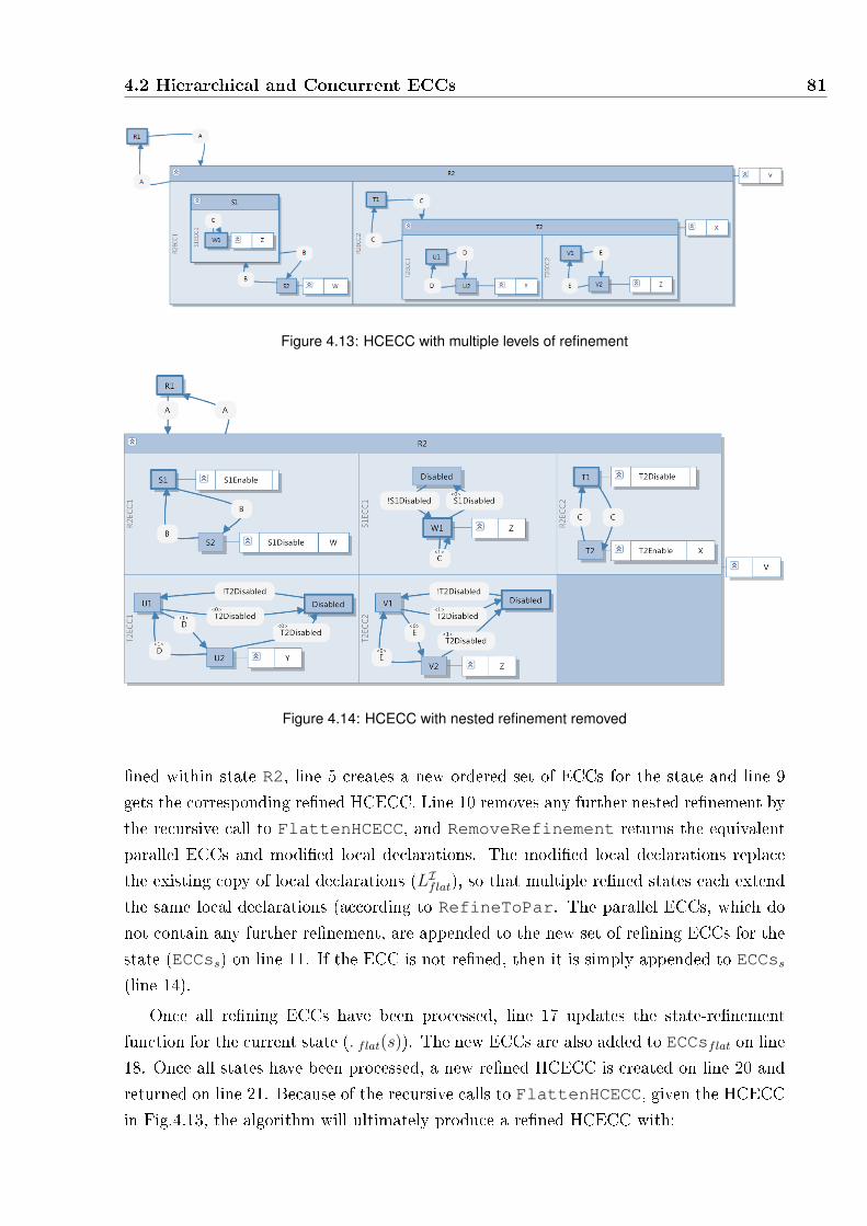
4.2 Hierarchical and Concurrent ECCs 81
Figure 4.13: HCECC with multiple levels of refinement
Figure 4.14: HCECC with nested refinement removed
�ned within state R2, line 5 creates a new ordered set of ECCs for the state and line 9
gets the corresponding re�ned HCECC. Line 10 removes any further nested re�nement by
the recursive call to FlattenHCECC, and RemoveRefinement returns the equivalent
parallel ECCs and modi�ed local declarations. The modi�ed local declarations replace
the existing copy of local declarations (LIflat), so that multiple re�ned states each extend
the same local declarations (according to RefineToPar. The parallel ECCs, which do
not contain any further re�nement, are appended to the new set of re�ning ECCs for the
state (ECCss) on line 11. If the ECC is not re�ned, then it is simply appended to ECCss
(line 14).
Once all re�ning ECCs have been processed, line 17 updates the state-re�nement
function for the current state (◃flat(s)). The new ECCs are also added to ECCsflat on line
18. Once all states have been processed, a new re�ned HCECC is created on line 20 and
returned on line 21. Because of the recursive calls to FlattenHCECC, given the HCECC
in Fig.4.13, the algorithm will ultimately produce a re�ned HCECC with:

82 Hierarchical and Concurrent ECCs for IEC 61499 Function Blocks
Input: Re�ned HCECC ⟨I, LI ,ECCI,LI= ⟨S, s0 , λ, T ⟩,ECCs, ◃⟩, MAP◃ (a map from an
ECC ECCi ∈ ECCs to a set of parallel ECCs (ECCsi) and a re�nement operator
(◃i) such that ⟨I, LI ,ECCi,ECCsi, ◃i⟩ is a re�ned HCECC)
Output: Flattened re�ned HCECC ⟨I, LIflat,ECC
I,LI
flat ,ECCsflat, ◃flat⟩1 LI
flat = LI ;
2 ECCsflat = ∅;3 Initialize ◃flat;4 foreach re�ned state s ∈ S do
5 Ordered set of ECCs ECCss := ∅;6 foreach ECCi ∈ ◃(s) do7 if MAP◃(ECCi) is not null then
8 (ECCsi, ◃i) = MAP◃(ECCi);9 Construct re�ned HCECC HCECC◃i = ⟨I, LI
flat,ECCi,ECCsi, ◃i⟩;10 Parallel HCECC ⟨I, LI
flat,ECCs′∥⟩ =
RemoveRefinement(FlattenHCECC(HCECC◃i, RefinedHCECCMap));11 ECCss = ECCss ⊕ (ECCs′∥);
12 end
13 else
14 ECCss = ECCss ⊕ ECCi;15 end
16 end
17 Set ◃flat(s) = ECCss;18 ECCsflat = ECCsflat ∪ ECCss;
19 end
20 Construct �attened HCECCret = ⟨I, LIflat,ECC
I,LI,ECCsflat, ◃flat⟩;
21 return HCECCret;Algorithm 4.8: Algorithm FlattenHCECC.
◃flat(R2) = {R2ECC1, S2ECC1, R2ECC2, T2ECC1, T2ECC2}.Each ECC will have been modi�ed from the original ECCs of the same names according
to one or more iterations of the re�nement operator.
Figure 4.15 shows the parallel HCECC that is the result after the re�ned HCECC
returned by FlattenHCECC (Fig. 4.14) is processed by RemoveRefinement to remove
the �nal level of hierarchy. All ECCs that had re�ned states have actions added to enable
and disable the re�ning ECCs. Similarly, all re�ning ECCs have a disabled state that is
used whenever the re�ned state is exited. Because of the �xed order of execution de�ned
by the parallel operator, a re�ning ECC only needs to react to the deactivation of the
state it is re�ning. For example, if the HCECC is in state W1 when event A happens:
• The re�nement of R2 will be disabled, disabling ECCs: R2ECC1 and R2ECC2.
• This in turn disables ECC S1ECC1.
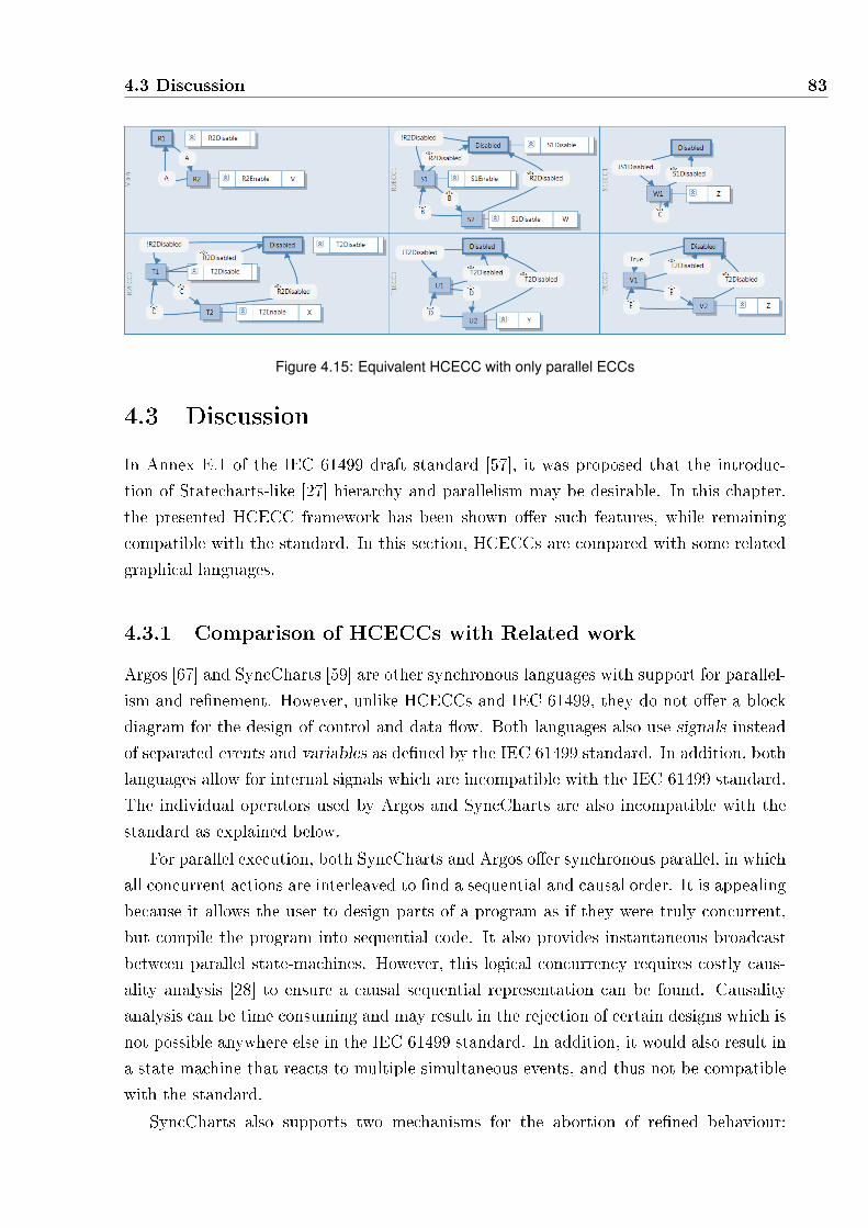
4.3 Discussion 83
Figure 4.15: Equivalent HCECC with only parallel ECCs
4.3 Discussion
In Annex E.1 of the IEC 61499 draft standard [57], it was proposed that the introduc-
tion of Statecharts-like [27] hierarchy and parallelism may be desirable. In this chapter,
the presented HCECC framework has been shown o�er such features, while remaining
compatible with the standard. In this section, HCECCs are compared with some related
graphical languages.
4.3.1 Comparison of HCECCs with Related work
Argos [67] and SyncCharts [59] are other synchronous languages with support for parallel-
ism and re�nement. However, unlike HCECCs and IEC 61499, they do not o�er a block
diagram for the design of control and data �ow. Both languages also use signals instead
of separated events and variables as de�ned by the IEC 61499 standard. In addition, both
languages allow for internal signals which are incompatible with the IEC 61499 standard.
The individual operators used by Argos and SyncCharts are also incompatible with the
standard as explained below.
For parallel execution, both SyncCharts and Argos o�er synchronous parallel, in which
all concurrent actions are interleaved to �nd a sequential and causal order. It is appealing
because it allows the user to design parts of a program as if they were truly concurrent,
but compile the program into sequential code. It also provides instantaneous broadcast
between parallel state-machines. However, this logical concurrency requires costly caus-
ality analysis [28] to ensure a causal sequential representation can be found. Causality
analysis can be time consuming and may result in the rejection of certain designs which is
not possible anywhere else in the IEC 61499 standard. In addition, it would also result in
a state-machine that reacts to multiple simultaneous events, and thus not be compatible
with the standard.
SyncCharts also supports two mechanisms for the abortion of re�ned behaviour:

84 Hierarchical and Concurrent ECCs for IEC 61499 Function Blocks
strong and weak abortion. Strong abortion terminates the behaviour of a re�ned state
at the beginning of a tick, while weak abortion would allow the re�ning ECC to transition
(or execute) once before exiting the state. As there is only one type of transition in IEC
61499, HCECCs are only able to employ one type of abortion. Because the re�nement op-
erator of HCECCs executes the re�ned ECC �rst in a tick, transitions exiting the re�ned
state act as a strong abort. However, because of the �xed order of execution, the re�ned
ECC will not be re-executed if re�ned ECCs change the values of variables in a tick. As
a result, unlike the strong abort in SyncCharts, transitions out of a re�ned state act as a
strong abort with conditions on internal variables based on values from the previous tick.
The synchronous languages Pret-C [75], SC [76] and Reactive-C [77] also use a �xed-
order parallel to avoid causality analysis, while still allowing concurrent behaviours to
be described. While Pret-C and Reactive-C only allow a textual de�nition of behaviour,
HCECCs o�er both algorithms and graphical components for the speci�cation. SC can be
generated from SyncCharts [59], simplifying the implementation, however, only HCECCs
are speci�cally tailored to be compatible with IEC 61499.
UML Statecharts [36] o�er many features for high-level modelling, including require-
ments modelling and software architecture design. The UML standard includes many
speci�cation diagrams such as sequence diagrams and class diagrams in addition to UML
Statecharts. HCECCs, on the other hand, provide fewer and more consistent design
elements that are better suited for system speci�cation. In addition, because UML is a
high-level language, it is less capable of modelling a plant in conjunction with a controller.
Finally, UML is object-oriented, unlike the component oriented IEC 61499 standard.
Other graphical formalisms such as NCES [66] and CNet [64] are based on tokens and
places instead of the �nite-state-machines presented by other languages. This di�erence
makes them less desirable, as HCECCs o�er a better visual representation for hierarchy
and concurrency. Both languages are also non-deterministic, which although bene�cial in
some applications, is undesirable within a basic function block.
A key bene�t of HCECCs is deterministic execution, attributable to the �xed order
evaluation of transitions and execution of parallel ECCs. This feature is not guaranteed
by SyncCharts and Argos. While the surveyed formal graphical languages o�er more
features for users, HCECCs uniquely o�er a compositional synchronous semantics with
hierarchy and concurrency while remaining compatible with the standard.
4.4 Conclusions
HCECCs simplify the design of control �ow by employing a structured state-machine ad-
opting an Statecharts or Argos-like approach for IEC 61499 ECCs. HCECCs present only
two of the operators used by Argos allowing for hierarchical and parallel ECCs, retaining

4.4 Conclusions 85
the compositionality of Argos. A hierarchy of ECCs can be used to e�ciently model ex-
ception handling, where a single transition can be used to pre-empt multiple behaviours.
Similarly, parallelism simpli�es the modelling of simultaneous sub-processes, and allows
for monitoring of simultaneous events within the developed synchronous semantics. Fea-
tures such as these greatly improve the maintainability of function block speci�cations,
allowing multiple function blocks with complicated ECCs to be refactored in a succinct
way. In addition, as shown in section 4.2, the use of a single state-machine makes it easier
to understand the overall behaviour of the conveyor model component. The semantics
remain compatible with the standard and use a syntax similar to IEC 61499 ECCs instead
of employing a separate graphical language for handling complex state-machine design.
HCECCs are used in the following chapter to simplify the design of a controller for
a baggage handling system. A compiler for the extended HCECC semantics is presented
later in Chapter 6, along with experimental comparisons with an earlier synchronous
semantics [30] and other execution approaches.

86 Hierarchical and Concurrent ECCs for IEC 61499 Function Blocks

5Re-Engineering IEC 61131-3 into IEC
61499 Function Blocks
Many existing IEC 61131-3 applications are large and complicated, representing many
man-hours of work, spread over a considerable period of time Because of this existing
investment, a new language is not su�cient to encourage better development practices on
its own. As a result, despite newer and more capable standards, there is still widespread
use of IEC 61131-3 in a range of industries. The reuse of existing code or architectures
would motivate the migration process by reducing the required investment of time and
simplifying the changes to the application.
This chapter presents an approach for the re-engineering of IEC 61131-3 speci�cations
into IEC 61499. The term, re-engineering, is the alteration of a system in order to recon-
stitute it into a new form [78]. This refers to the adoption of parts of existing IEC 61131-3
code and creating a new speci�cation in IEC 61499 that implements the same behaviour.
In order to facilitate migration, a mapping of IEC 61131-3 elements into IEC 61499 is
proposed to reconcile the di�erences in the two standards. From this mapping, an IEC
61131-3 application can be re-engineered into a model-driven and component-based design
using function blocks. Compared to the original implementation, the resulting function
blocks are easier to reuse and the function block standard allows for more execution
platforms.
This chapter begins with the description of a baggage handling system (BHS) control-
87

88 Re-Engineering IEC 61131-3 into IEC 61499 Function Blocks
ler designed using IEC 61131-3 in Section 5.1. Section 5.2 describes the proposed map
of IEC 61131-3 elements into equivalent IEC 61499 components. Section 5.3 presents the
re-engineering approach, using the example BHS controller to demonstrate key aspects.
Results obtained from the IEC 61499 implementation of the BHS are discussed in Sec-
tion 5.4. Finally, Section 5.5 gives some concluding remarks and identi�es avenues for
further research.
5.1 IEC 61131-3 speci�cations
First published in 1993, the goal of IEC 61131-3 [4] was to de�ne a consistent syntax and
semantics for 5 di�erent programming languages, which had been already been in use in
industry. IEC 61131-3 is most often used in industrial control systems and executed on
Programmable Logic Controllers (PLCs). The standard is widely accepted by industry,
with most PLCs and industrial development environments supporting at least some of the
languages. Unfortunately, many manufacturers still retain incompatible aspects of their
original proprietary implementations.
By modern standards, the languages of IEC 61131-3: Ladder Logic Diagram (LLD),
Function Block Diagram (FBD), Structured Text (ST) and Instruction List (IL) lack many
features. In particular, the absence of object-oriented structure complicates component
separation, forcing routines to encompass unrelated functionalities. Similarly, code that
is speci�c to a platform or hardware con�guration is also integrated with general control
logic. Further, PLCs and their programming languages are designed for centralised mono-
lithic designs. As a result, distribution of IEC 61131-3 applications must be factored into
the design from the initial planning phase.
The most common platform for IEC 61131-3 languages are PLCs, which are industrial
controllers capable of handling many input and output ports. PLCs execute using what is
known as a scan-cycle, visualised in Figure 5.1(a). In a scan-cycle, the controller samples
the inputs, executes the routines and writes to outputs. This approach simpli�es code
development, allowing developers to write code that does not account for input values
changing during code execution.
IEC 61131-3 encapsulates the code for a PLC in a con�guration, illustrated in Fig-
ure 5.1(b), which contains all aspects of the control logic and global variables. The
controller is divided into Tasks, similar to a processes, which are activated periodically
or on the occurrence of certain events. When activated, a Task will execute one or more
programs, which are a collection of routines, with a main routine which controls the ex-
ecution of the program. For example, a task may be triggered on the start-up of the
PLC and execute an initialisation program that initialises variables used in the control-
ler programs. IEC 61131-3 supports global variables, declared as part of the controller's

5.1 IEC 61131-3 speci�cations 89
Read Inputs
Computation
Set Outputs
(a) Illustration of PLC scan-
cycle execution
Configuration
Task
ProgramMainRoutineRoutine1
Routine2
Routine3
ProgramMainRoutineRoutine1
Routine2
Routine3
Global Variables
Program Variables Program Variables
(b) Software structure de�ned by IEC 61131-3
Figure 5.1: IEC 61131-3 Overview
con�guration, and scoped variables shared as part of the declaration of a program. These
program variables can only be used in routines allocated to the program.
5.1.1 Design of a Baggage Handling System
The controller for a baggage handling system (BHS) will be used to illustrate the develop-
ment of an IEC 61131-3 application, and illustrate the proposed re-engineering approach.
A simple BHS consists of a network of conveyor belts which form redundant routes from
a single check-in input location to multiple aircraft loading zones. Each physical con-
veyor is comprised of a rotary encoder, which measures the distance traveled by the belt,
and infra-red bed detectors called photo-eyes, which indicate the positions of bags. The
controller uses these inputs to identify the leading and trailing edges of bags, for accur-
ate positioning. The control approach adds multiple entry and exit pseudo-devices, where
entry devices are responsible for inserting bags into the model of bags on the conveyor and
exit devices hand over exiting or diverting bags to an entry device on the next conveyor.
The BHS controller is implemented in two IEC 61131-3 tasks, one for fast and high
frequency monitoring of inputs and another for the slower bag tracking and routing al-
gorithms. They will be referred to as the fast and slow tasks respectively. The fast
task maintains the absolute distance traveled by each conveyor belt by monitoring the
state of the attached rotary encoders. It also detects the leading and trailing edges of bags
using inputs from the photo-eyes. To maintain an accurate count of the distance a belt
has traveled, the fast task must read every state change of the rotary encoder. When the
conveyor is running at its maximum speed of 1.5 ms−1 the rotary encoder changes state
once per 26 ms. As such, the fast task is triggered every 25ms, with the slow task given
a slower period of 200ms to perform its more computationally intensive operations. The

90 Re-Engineering IEC 61131-3 into IEC 61499 Function Blocks
PLC is con�gured to execute the slow task in the unused time between the completion of
the fast task, and the next 25ms trigger. Thus the slow task is continually preempted by
the fast task, as illustrated in Figure 5.2. Communication between the fast and slow tasks
use global variables with additional bu�ers for variables within the slow-task. Bu�ering
of some variables is required so that when execution of the slow task is interrupted by the
fast task the variables it uses are consistent.
Figure 5.2: Timing Diagram Illustrating Execution Schedule for two tasks
To illustrate IEC 61131-3 programming, an excerpt of the ladder logic routine for
allocating a new bag identi�cation number is shown in Figure 5.3. In ladder logic, routines
are divided into rungs and instructions. A a rung is a horizontal segment of the ladder
logic drawn as a horizontal line similar to a rung on a ladder. Rungs are used to group
instructions together, and are executed one at a time, and from top to bottom. Individual
instructions are executed sequentially, but only if previous conditional instructions on
the same rung evaluate to true. The screen shot is taken from the RSLogix integrated
development [79] from Rockwell [23], with the rung numbers listed on the left. The SBR
instruction on rung 0 declares the inputs to the function, and the MOV instruction assigns
ABID_ResultCode to a default error code, in case of failure. Rung 1 contains an ADD
instruction to increment a stack pointer, but the GRT instruction is used to conditionally
reset it to 0 if it exceeds the size of the array. Context information is then added to the
ErrorContextStore regardless of the GRT instruction due to the empty branch around
the conditional statement. Notice that branches act as a type of pseudo-instruction that
alters the �ow of execution. In Rung 2, if the function has already set the boolean �ag
ABID_InitComplete then it will jump to the CODE label. Otherwise execution will
continue on the next rung.
While the format of LLD is bene�cial for electrical professionals who are more used to
electronic circuits using relays and contacts, the graphical format is verbose and wasteful
for many operations. The mix of horizontal and vertical execution across the syntax is
also more complicated than other languages, such as Structured Text or C. For all IEC
61131-3 languages, however, the nature of a �at application comprised solely of routines
makes it di�cult to identify and reuse system components. Single functions may be
used to implement the behaviour for multiple components, obscuring the interactions
between the components. This is more common in time dependent tasks, in which many
functionalities can be merged into a single function in order to minimise the time spent in

5.2 Proposed Mapping of IEC 61131-3 to IEC 61499 91
Figure 5.3: LLD sample including complex Branch behaviour
context switching between routines. The next section presents a proposal for the mapping
of IEC 61131-3 design features into IEC 61499 components.
5.2 Proposed Mapping of IEC 61131-3 to IEC 61499
The IEC 61499 [15] open standard attempts to address the inadequacies of IEC 61131-3
by introducing a design framework using event-triggered function blocks as distributable
components. The hardware independence of a function block application allows a single
speci�cation to be compiled for a number of di�erent platforms. A controller can there-
fore be tested on other platforms, prior to deployment to a PLC, enabling the use of
better debugging facilities. Function blocks are also capable of modelling the behaviour
of physical hardware, allowing a controller to be tested more rigorously with a simulated
system.
While the IEC 61131-3 and IEC 61499 standards have di�erent execution approaches,
(cyclic and event-triggered respectively), similarities in some of the design components
allow direct translation. Table 5.1 shows a summary of IEC 61131-3 design elements and
the nearest equivalent element in IEC 61499. Tasks, which describe the activation of a
program, correspond to one possible reaction of a resource in response to an particular
external event or periodic interval. Programs correspond directly to an IEC 61499 re-
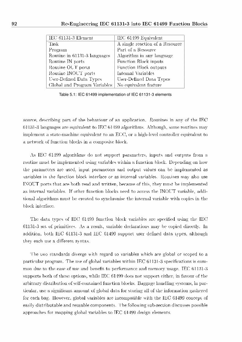
92 Re-Engineering IEC 61131-3 into IEC 61499 Function Blocks
IEC 61131-3 Element IEC 61499 EquivalentTask A single reaction of a ResourceProgram Part of a ResourceRoutine in 61131-3 languages Algorithm in any languageRoutine IN ports Function Block inputsRoutine OUT ports Function Block outputsRoutine INOUT ports Internal VariablesUser-De�ned Data Types User-De�ned Data TypesGlobal and Program Variables No equivalent feature
Table 5.1: IEC 61499 implementation of IEC 61131-3 elements
source, describing part of the behaviour of an application. Routines in any of the IEC
61131-3 languages are equivalent to IEC 61499 algorithms. Although, some routines may
implement a state-machine equivalent to an ECC, or a high-level controller equivalent to
a network of function blocks in a composite block.
As IEC 61499 algorithms do not support parameters, inputs and outputs from a
routine must be implemented using variables within a function block. Depending on how
the parameters are used, input parameters and output values can be implemented as
variables in the function block interface or as internal variables. Routines may also use
INOUT ports that are both read and written, because of this, they must be implemented
as internal variables. If other function blocks need to access the INOUT variable, addi-
tional algorithms must be created to synchronise the internal variable with copies in the
block interface.
The data types of IEC 61499 function block variables are speci�ed using the IEC
61131-3 set of primitives. As a result, variable declarations may be copied directly. In
addition, both IEC 61131-3 and IEC 61499 support user de�ned data types, although
they each use a di�erent syntax.
The two standards diverge with regard to variables which are global or scoped to a
particular program. The use of global variables within IEC 61131-3 speci�cations is com-
mon due to the ease of use and bene�t to performance and memory usage. IEC 61131-3
supports both of these options, while IEC 61499 does not support either, in favour of the
arbitrary distribution of self-contained function blocks. Baggage handling systems, in par-
ticular, use a signi�cant amount of global data for storing all of the information gathered
for each bag. However, global variables are incompatible with the IEC 61499 concept of
easily distributable and reusable components. The following sub-section discusses possible
approaches for mapping global variables to IEC 61499 design elements.
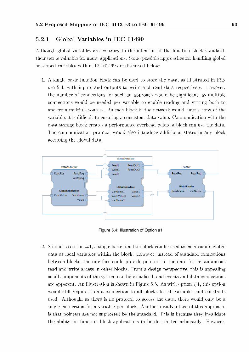
5.2 Proposed Mapping of IEC 61131-3 to IEC 61499 93
5.2.1 Global Variables in IEC 61499
Although global variables are contrary to the intention of the function block standard,
their use is valuable for many applications. Some possible approaches for handling global
or scoped variables within IEC 61499 are discussed below:
1. A single basic function block can be used to store the data, as illustrated in Fig-
ure 5.4, with inputs and outputs to write and read data respectively. However,
the number of connections for such an approach would be signi�cant, as multiple
connections would be needed per variable to enable reading and writing both to
and from multiple sources. As each block in the network would have a copy of the
variable, it is di�cult to ensuring a consistent data value. Communication with the
data storage block creates a performance overhead before a block can use the data.
The communication protocol would also introduce additional states in any block
accessing the global data.
Figure 5.4: Illustration of Option #1
2. Similar to option #1, a single basic function block can be used to encapsulate global
data as local variables within the block. However, instead of standard connections
between blocks, the interface could provide pointers to the data for instantaneous
read and write access in other blocks. From a design perspective, this is appealing
as all components of the system can be visualised, and events and data connections
are apparent. An illustration is shown in Figure 5.5. As with option #1, this option
would still require a data connection to all blocks for all variables and constants
used. Although, as there is no protocol to access the data, there would only be a
single connection for a variable per block. Another disadvantage of this approach,
is that pointers are not supported by the standard. This is because they invalidate
the ability for function block applications to be distributed arbitrarily. However,

94 Re-Engineering IEC 61131-3 into IEC 61499 Function Blocks
data could be synchronised between multiple resources in a number of ways with
service interface function blocks. For example, a possible service interface function
block could implement a type of critical section, where the global variable pointer
can only be used within the critical section.
Figure 5.5: Illustration of Option #2
3. As suggested by Sunder et al. [80], the resource or run-time environment could
provide global data storage, and service interface function blocks could be used to
read and write to the data. Graphically similar to option #1, this approach would
provide the user with a complete visualisation of data connections and usage. Sunder
et al. do note that di�culties would arise if a block reads and writes to a variable
within an algorithm, as the two values would need to be synchronised after every
write. Once again like option #1, inter-block connections introduce performance
over-head. Also, memory would be wasted on copies of the variables within each
block. Synchronisation of data values would also be complicated if resources are
able to pre-empt each other. In particular, when a resource is pre-empted before a
block has transferred local changes into the global storage.
4. Dai et al. in [81] suggest that global variables can be removed by employing a class-
oriented design approach, instead of the traditional component-oriented approach.
Using this approach, a class combines all related functions into a single basic function
block so that internal variables can be used. This approach still allows for a class
to be used in distributed deployment, by the use of con�guration parameters for
di�erent instances of the same class block in di�erent resources. As behaviours in a
class are restricted to a single function block, only one ECC can be used, with other
state-like behaviour implemented as algorithms. The model-view-controller design
approach is also not possible with class-oriented control.
5. It is possible to link arbitrary C code together with the C code generated by the

5.3 Proposed Approach 95
(FBC) [30] synchronous compiler for IEC 61499 at compile time. This can be used
to provide global variables and constants to the application. This approach means
that at the level of the function block design, there is no indication of the global
variables used. Algorithms within basic function blocks would simply have direct
access to these variables. It would also allow global constants to be used in the input
parameters of blocks. As the function block application is separate from variable
declarations, spelling mistakes or connections to unde�ned constants could only be
identi�ed at compile time. In addition, accidental variable misuse would be di�cult
to debug.
Semantically this approach can be thought of as the use of internal variables for a
device, instead of just within a basic function block as per the standard. This o�ers
many bene�ts including: reduced memory usage compared to Option #1 (because
there is only a single copy of each value), and improved performance by mitigating
overhead from event-data associations and block connections. This option is also
appealing because it makes the function block design very simple and it would be
easy to change the complier.
For this work, linking to a library of global variables was chosen because it is simple
to implement and does not require any modi�cations to the translated LLD routines.
However, as with most other proposals, it will be incompatible with the standard and other
function block compilers. For industrial automation and resource constrained embedded
systems, this trade-o� is valuable because of the improved performance.
The current implementation assumes the execution semantics provided by FBC and
requires that a resource cannot be preempted. This ensures that access to global variables
is atomic. Within a resource, the synchronous semantics used by FBC already ensures
atomic operations. A di�erent approach is necessary to handle the case where resources
can be preempted, possibilities for this future work are discussed in Section 5.5.
5.3 Proposed Approach
A general tool for reverse engineering of IEC 61131-3 code is hindered by the propri-
etary implementations of the di�erent manufacturers. Instead only a generalised process
is possible, with manufacturer speci�c adjustments to the intermediate steps. This work
develops tools for use with Rockwell's RSLogix [79] integrated development environment
(IDE). To demonstrate the approach, the BHS controller introduced in Section 5.1.1 is
translated into IEC 61499 function blocks.
Figure 5.6 illustrates the proposed re-engineering process from IEC 61131-3 into IEC

96 Re-Engineering IEC 61131-3 into IEC 61499 Function Blocks
61499. The translation of IEC 61131-3 LLD into C code is automated but vendor speci�c,
whilst the other processes remain manual and generic. The function block interfaces of the
lowest level components will re�ect the required hardware inputs and outputs, and most
blocks will include inputs for con�guration parameters. Basic function blocks are manually
created to execute the algorithms of a single component. The ECC for such a block may
be based on an original LLD routine or, alternatively, an ECC can simply execute an
algorithm whenever inputs are updated. Composite blocks can be created, as required, to
group dependent components. Once the function block architecture is completed, the C
functions obtained by translation of the textual LLD code can be inserted into the basic
function block of the relevant component. Execution of the IEC 61499 system is achieved
by linking the C code generated by FBC with global data declarations stored in standard
C �les.
Configuration
Task
ProgramMainRoutineRoutine1
Routine2
Routine3
ProgramMainRoutineRoutine1
Routine2
Routine3
Global Variables
Program Variables Program Variables
IEC 61499
Architecture
Textual
TranslationAutomated
Creation of
Function BlocksManual
Algorithm
integrationManual
Collection of
C code
Application
Compilation
and
LinkingAutomated
Global Data
Declarations
Figure 5.6: Migration plan from IEC 61131-3 to IEC 61499
This approach focuses on automated direct translation of the low-level code instead
of identifying and re-creating the architecture of the system from code. This approach
was chosen because the structure of IEC 61131-3 applications can vary greatly. As such,
the translation of routines can be automated, but the automated generation of objects
or components is not possible. The integration of generated C code into function blocks
results in a platform independent implementation that can be easily reused. The proposed
re-engineering process is therefore comprised of the following steps:
• Function block interfaces are created for each component in the system.
• Function blocks for commonly grouped sub-components are encapsulated into a
higher level composite block, until there is one function block per physical compon-
ent.
• LLD code is exported from RSLogix IDE in a proprietary textual format. Rockwell
uses the extension L5K for the text �le describing every element of the IEC 61131-3
con�guration.

5.3 Proposed Approach 97
• A manufacturer dependent lexical parser creates an Abstract Syntax Tree (a tree
representation of the abstract syntactic structure of textual source code) for the
complete IEC 61131-3 application.
• The syntax tree is traversed and global variables, data structures and functions are
generated in C code according to the manufacturer's semantics for IEC 61131-3
LLD.
• The generated C functions are manually grouped according to the relevant physical
component and imported as algorithms into the basic function block for the com-
ponent. Some state-based functions can alternatively be manually re-implemented
as an HCECC (introduced in Chapter 4).
• System redesign can be managed by altering connections between these top-level
component blocks.
In this work, the resulting IEC 61499 application will be executed by using the FBC
synchronous compiler developed by Yoong et al. [82] and improved in Chapter 6. This
execution approach was selected because the synchronous semantics are similar to the
PLC scan-cycle and execution performance is of crucial importance to many industries
including BHSs. FBC has also been shown in a number of tests to use less memory and
execute more quickly than the available alternatives (see Chapter 6 or [30]).
While function block algorithms can be written in any of the IEC 61131-3 languages,
languages such as C, C++ and Java (used in FBC [82], FORTE [40] and FBDK [39]
respectively) are preferred as they are better suited for cross-platform development. It is
therefore proposed that all of the routines from the PLC implementation are translated
into C code for use with the FBC compiler. As basic function block algorithms do not
support arguments, a generated C function is imported by �rst modifying it to use vari-
ables from the block's interface. In the case of routines that use INOUT variables, such
variables are implemented as internal variables in the basic function block. If the variable
is also used in other function blocks, the algorithm can be modi�ed to read and write to
the interface and use a local variable for internal processing.
5.3.1 Function Block Development
For the BHS example, the fast and slow IEC 61131-3 tasks and their respective programs
could be created as two resources. However, separation of the control into two di�erent
resources would necessitate two function blocks per conveyor section, making it more
di�cult to manage. Implementing two resources may also be useful if the target hardware
for the function block application is not capable of running both programs within the

98 Re-Engineering IEC 61131-3 into IEC 61499 Function Blocks
fast-task's 25ms dead-line. As an alternative, the two tasks could be created as a single
resource, with two events activating di�erent reactions within the function block network.
For this work, it is assumed that executing on a PC and possibly an industrial con-
troller will be su�ciently fast. As such, all functionalities are composed together within a
single composite block to represent a single component. If performance deadlines are not
met, the function block application can be divided such that a single controller controls
fewer components. Communication between multiple controllers can be implemented sim-
ilar to the IEC 61131-3 implementation, using service interface function blocks to transmit
messages over a network connection.
When compared to IEC 61131-3, the IEC 61499 standard provides the most bene�t
when a closed-loop model of the plant and controller is developed, allowing complete func-
tional testing of the controller. Following the model-view-controller design pattern [11], at
the top most speci�cation level, two resources should be de�ned to encapsulate the plant
and controller subsystems. For this chapter, the plant model explained in Chapter 3 will
be used. This allows complete functional testing of the controller prior to the construction
of the physical BHS. The visualisation of each component further provides a much greater
view of the running system, and provides contextual information which is useful for de-
bugging. The re-engineered controller resource will be comprised of a simple network of
blocks representing the components in the BHS, into which the generated C code will be
inserted.
The components used in an IEC 61131-3 implementation can be determined by ana-
lysing the user-de�ned data types (UDTs) de�ned in the con�guration. UDTs provide
all of the variables required by a component in the original implementation, this can be
used to de�ne the interface for the function block re-implementation. Some components
may also encapsulate other components, shown either by the UDT or knowledge of the
hardware. In such cases, a composite function block should also be created for the com-
ponent, which contains the embedded components (as well as the basic function block for
the component itself).
For this implementation, the original UDT for a conveyor section includes many con�g-
uration variables so that all conveyors are instances of the same type. Therefore, a single
function block was created for a conveyor, with all of the parameters for any conveyor
type, including variable numbers of merge and divert points. In this way, all conveyors in
the system can be created in a network by using a single component block with di�erent
con�guration parameters. An alternative approach is to develop a function block compon-
ent for each conveyor con�guration type, pre-setting variables instead of exposing them in
the interface of a fully parametrised block. While this would reduce the complexity of the
function block network in the controller resource, it would be more di�cult to maintain
the di�erent con�gurations.
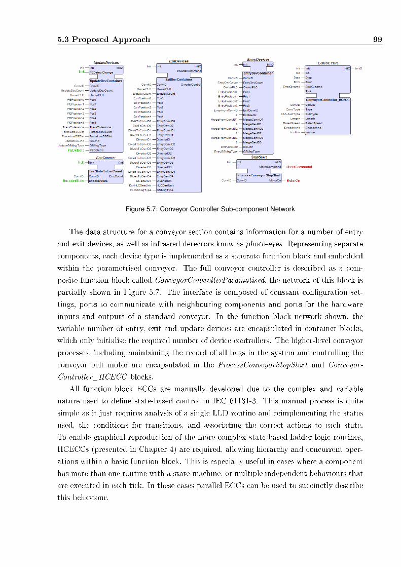
5.3 Proposed Approach 99
Figure 5.7: Conveyor Controller Sub-component Network
The data structure for a conveyor section contains information for a number of entry
and exit devices, as well as infra-red detectors know as photo-eyes. Representing separate
components, each device type is implemented as a separate function block and embedded
within the parametrised conveyor. The full conveyor controller is described as a com-
posite function block called ConveyorControllerParamatised, the network of this block is
partially shown in Figure 5.7. The interface is composed of constant con�guration set-
tings, ports to communicate with neighbouring components and ports for the hardware
inputs and outputs of a standard conveyor. In the function block network shown, the
variable number of entry, exit and update devices are encapsulated in container blocks,
which only initialise the required number of device controllers. The higher-level conveyor
processes, including maintaining the record of all bags in the system and controlling the
conveyor belt motor are encapsulated in the ProcessConveyorStopStart and Conveyor-
Controller_HCECC blocks.
All function block ECCs are manually developed due to the complex and variable
nature used to de�ne state-based control in IEC 61131-3. This manual process is quite
simple as it just requires analysis of a single LLD routine and reimplementing the states
used, the conditions for transitions, and associating the correct actions to each state.
To enable graphical reproduction of the more complex state-based ladder logic routines,
HCECCs (presented in Chapter 4) are required, allowing hierarchy and concurrent oper-
ations within a basic function block. This is especially useful in cases where a component
has more than one routine with a state-machine, or multiple independent behaviours that
are executed in each tick. In these cases parallel ECCs can be used to succinctly describe
this behaviour.

100 Re-Engineering IEC 61131-3 into IEC 61499 Function Blocks
Figure 5.8 shows the ECC for the PhotoEye Controller block, nested within the Up-
dateDevContainer composite block. This ECC re-implements the routine in Figure 5.9
in a much simpler and easier to maintain format. The data handling from the routine is
extracted from the generated C code and separated into algorithms to be called by the
various states. The use of ECCs instead of sequential code simpli�es control �ow design
and maintenance, by replacing many lines of code with an intuitive graphical design.
Figure 5.8: PhotoEyeController ECC
LBL
NO_BAG
] [
PEDetect JamFault
] [ JMP
ENTER_LEADING_OBJECT
LBL
LEADING_OBJECT
] [
PEDetect
JMP
ENTER_NO_BAG
LES
AssocObjectDistance
<
ASSOC_OBJ_DISTANCE_MAX
JMP
END_PE
] [
PEDetect
GRT
AssocObjectDistance
>
ASSOC_OBJ_DISTANCE_MAX
JMP
ENTER_BAG
JMP
END_PE
LBL
ENTER_LEADING_OBJECT // Store start of BagDetect, update AssocObjectDistance"
Figure 5.9: Section of a State-machine written in LLD
In the absence of a routine that implements a state-machine for a particular compon-
ent, active and inactive state-like behaviour can be introduced. For the speci�cation of
the main controller block, ConveyorController_HCECC, shown in Figure 5.10, HCECCs

5.3 Proposed Approach 101
are used to represent the concurrent tasks. Without a strict state-machine routine, the
top level HCECC is instead used to distinguish between initialisation, error and running
states. When running in the NORMAL state, the concurrent tasks execute one of the
required C functions to recreate the behaviour of the LLD implementation. These al-
gorithms check and process the global memory written to by the other components in the
conveyor controller. The PublishBagData ECC is also added to allow a visualisation
to display the model of bags as seen by the controller. The visualisation can be used to
detect errors in the control code, by comparing the controller's perceived bag positions,
with actual positions from the plant model.
Figure 5.10: Conveyor Controller HCECC
The full controller sub-system is created by instantiating and connecting multiple in-
stances of the ConveyorControllerParamatised block. LLD routines which access
the PLC's inputs and outputs are replaced with service interface function blocks, which
use sockets to communicate with the plant model in the plant resource. These communic-
ation blocks can be easily replaced later to access hardware inputs and outputs instead.
5.3.2 PLC Parsing
The LLD routines, user-de�ned data types and variable declarations are all exported
from RSLogix into a single textual format. The textual format, stored in a �le with
the extension L5K, conserves the rung and instruction order of the routines and includes
meta-data about the controller. A parser for the L5K �le was developed using a grammar
created using JavaCC [83].
Algorithm 5.1 shows Rockwell's textual representation of the AllocateBagID ladder
logic routine shown in Figure 5.3. An additional instruction (line 13) was added to show a

102 Re-Engineering IEC 61131-3 into IEC 61499 Function Blocks
complete routine in L5K, and newlines were added for readability. The name of the routine
is obtained as a token after the keyword ROUTINE, other information such as the inputs
and outputs must be determined by examining the instructions. All instructions are of
the form Identifier(arguments...), and are stored in the AST (Abstract Syntax Tree) as
an Instruction node with all arguments stored as an ordered array of child nodes. The
SBR instruction on line 2 declares the start of a routine, where the instruction arguments
indicate the inputs to the routine. Similarly, the RET instruction on line 13, indicates the
outputs for the routine. Any variables identi�ed in both SBR and RET instructions are
actually inout ports, which can be both read and written to.
When the start of a rung is detected with the token 'N:', instructions are stored in
an ordered list of child tokens for the rung. When outside the context of instruction
arguments, the branch pseudo-operation begins with the token '[', as seen at the start
of line 5. Each sub-rung of a branch, separated by a comma in the L5K �le, is stored
in order within the branch node in the AST. A sub-rung is stored as a standard rung
with ordered instructions, which may also contain additional branch instructions. For
example, in this case the GEQ and MOV instructions are stored in the �rst sub-rung, and
the second sub-rung is empty. The semantics of the branch instruction is discussed in
the next sub-section with regard to equivalent behaviour in C. Code comments, starting
with the token 'RC:', are also parsed into the AST. Translation from the generated AST
is possible by determining an equivalent statement or function for each instruction.
1 ROUTINE AllocateBagID2 N: SBR(ABID_MinBagID,ABID_MaxBagID,ABID_LastBagID)3 MOV(RESULTCODE_UNKNOWNERROR,ABID_ResultCode);4 N: ADD(ErrorContextStore.StackPtr, 1, ErrorContextStore.StackPtr)5 [GEQ(ErrorContextStore.StackPtr,ErrorContextStore.SIZE)6 MOV ( 0, ErrorContextStore.StackPtr ) , ]7 MOV(THIS_PLC_SUBSYSTEM_ID,8 ErrorCon-
textStore.Context.Entry[ErrorContextStore.StackPtr].SubSystemID);9 MOV(UNIT_ALLOCATEBAGID,10 ErrorCon-
textStore.Context.Entry[ErrorContextStore.StackPtr].SoftwareUnit);11 N: XIC(ABID_InitComplete)JMP(CODE);12 RC: Additional Rung13 N: RET(ABID_ResultCode);14 END_ROUTINE
Algorithm 5.1: Textual format of Ladder Logic Rung

5.3 Proposed Approach 103
5.3.3 Code generation
An application developed speci�cally for Rockwell's LLD semantics generates equivalent
C code from the syntax tree created by the parser. This program, called L5K2C, includes
a mapping of all LLD instructions into equivalent C statements or functions as well as a
map relating standard IEC 61131-3 data types into C primitives. The behaviour of each
instruction was obtained from documentation in [84]. More complicated instructions, such
as the Branch pseudo-instruction are handled in special functions in order to generate both
semantically equivalent and human readable code.
L5K2C walks through the tree and stores di�erent collections of information into
separate �les. For example, user-de�ned data types in the L5K �le are all stored in
a single sequence, these are saved in a single C header �le as structs, using the C
equivalent of the primitive IEC 61131-3 data types. Within IEC 61131-3, data types,
variables and routines can have the same name, causing con�icts in directly translated
statements. When generating C code, L5K2C modi�es any declaration to ensure global
uniqueness. In the case of user-de�ned data types, the names of the generated structs
are modi�ed to include "`Struct"' as a su�x.
When L5K2C traverses global and program variable nodes in the AST, variables are
generated in a �le speci�c to the relevant scope in order to allow controlled inclusion of
variables. Unlike user-de�ned data types and routines, the names of global variables are
not changed so that L5K2C does not need to change all occurrences of global variables
in translated routines. Variables from a program scope are modi�ed however because
they may overlap with variables in other programs. Each generated declaration uses
the equivalent C primitive type, or the translated user-de�ned data type with the su�x
"`Struct"' appended.
Each routine is generated in a separate C �le, which begins with some #include
directives to include the global variable declarations, as well as variables scoped to the
program the routine is part of. As with user-de�ned data types, the names of routines
can also have the same name as routines in other programs. Following the same approach
as with variables, all routines are given a pre�x of the program name. The modi�ed name
of the routine is also used as the name of the C �le. As stated earlier, the names of global
variables are unchanged to minimise changes to the routines. Local variables are also
left unchanged as they cannot overlap with any other set of variables. Only instruction
arguments which reference variables from program scopes are generated with the pre�x
of the program name, as they may overlap with other programs.
Algorithm 5.2 shows the procedure for the generation of C code from a routine. The
whole routine is searched for the SBR and RET instructions to determine the inputs and
outputs of the function (lines 4-5). INOUT ports are then determined and removed from
the sets of inputs and outputs (lines 6-9). The data type for each of the arguments to

104 Re-Engineering IEC 61131-3 into IEC 61499 Function Blocks
1 procedure L5K2C_Routine(routine)2 programname := program name that routine belongs to;3 name := name of the routine;4 I := the set of inputs obtained from parameters of SBR instruction;5 O := the set of inputs obtained from parameters of RET instruction;6 foreach io ∈ I which are also ∈ O do7 append io to new set IO, the set of input-output variables;8 remove io from both I and O;9 end10 Get data types for I, O, IO variables from known scopes;11 generate declaration for routine using the format:12 void programname_name(type i ∈ I, type *io ∈ IO, type *o ∈ O);13 L := ordered set of rungs and comments in routine;14 foreach l ∈ L do15 if l is rung then16 foreach child ∈ l do17 if child is instruction then18 generate C statement for instruction using look-up table;19 end20 else if child is branch then21 generate each sub-rung as a normal rung;22 generate if statement to test if the simpli�ed condition of all
conditions in any one rung is met;23 print remaining child ∈ l within scope of if statement;24 end25 end26 end27 else if l is a comment then28 generate multi-line C comment using the contents of l;29 end30 end31 end procedure
Algorithm 5.2: Algorithm for the translation of LLD to C
the routine are discovered by checking the lists of global and program variables (line 10).
Only then can the de�nition for the function be generated, with a void return type as all
of the inputs and outputs of the function are stored as arguments (lines 11-12).
The ordered set of rungs and routines is iterated over to generate the semantically
equivalent C statements (lines 13-30). Every child of a rung node in the AST repres-
ents an instruction or branch node, and the children of either node represent ordered
arguments. When generating code for an LLD instruction, a look-up table is used to
generate the equivalent C statement (line 18). A custom template syntax is used to
programmatically generate the C code for each instructions. In the case of the ADD in-
struction, the C template is $3 = $1 + $2;, where the numbered tokens are replaced with

5.3 Proposed Approach 105
the text of appropriate child node. For example, ADD(V ar1, V ar2, V ar1) is generated
as V ar1 = V ar1 + V ar2;. To match the renamed program variables, any instruction ar-
guments that match the name of a program variable are pre�xed with the program name.
Some instructions need to be handled more dynamically than templates allow. Instruc-
tions such as JSR(V ar1, V ar2, ...) accept a variable number of arguments, so it must be
handled specially. In the case of JSR, a function call is generated in C, which calls the
function ProgramName_V ar1 with any remaining arguments passed as arguments to
the C function.
The branch pseudo-instruction complicates compilation due the semantics of the con-
trol �ow it represents (lines 20-24). Using Figure 5.11 as an example, the semantics of
the relatively simple looking LLD require that the MOV instruction must be executed if
B is true, regardless of A, C and D. Finally, the output O must only be emitted if A or
B or C or D is true.
Figure 5.11: Branch in LLD
In C code, this type of behaviour is implemented by in Alg. 5.3. Each sub-rung is
generated in the same way as a standard rung, though conditional statements are also
tracked for later reuse. Instructions after the branch are encapsulated in an if statement
which represents whether control �ow in the LLD implementation activated the right
hand side of the branch by satisfying the conditions on at least one sub-rung.

106 Re-Engineering IEC 61131-3 into IEC 61499 Function Blocks
1 if( A ){2 . . .3 }4 if( B ){5 Y = X;6 }7 if( C ){8 . . .9 }10 if( D ){11 . . .12 }13
14 if( A || B || C || D ){15 O = true;16 }
Algorithm 5.3: Equivalent Behaviour in C
1 ROUTINE AllocateBagID2 N: SBR(ABID_MinBagID,ABID_MaxBagID,ABID_LastBagID)3 MOV(RESULTCODE_UNKNOWNERROR,ABID_ResultCode);4 N: ADD(ErrorContextStore.StackPtr, 1, ErrorContextStore.StackPtr)5 [GEQ(ErrorContextStore.StackPtr,ErrorContextStore.SIZE)6 MOV ( 0, ErrorContextStore.StackPtr ) , ]7 MOV(THIS_PLC_SUBSYSTEM_ID,8 ErrorCon-
textStore.Context.Entry[ErrorContextStore.StackPtr].SubSystemID);9 MOV(UNIT_ALLOCATEBAGID,10 ErrorCon-
textStore.Context.Entry[ErrorContextStore.StackPtr].SoftwareUnit);11 N: RET(ABID_ResultCode);12 END_ROUTINE
Algorithm 5.4: Textual format of Ladder Logic Rung
A sub-section of the routine shown in Algorithm 5.1 is reproduced in Algorithm 5.4
to demonstrate the procedure when generating the C code shown in Algorithm 5.5. The
algorithm name is AllocateBagID, within the program SlowProgram. From the SBR
instruction (seen only in Algorithm 5.1) the set of inputs, I, contains ABID_MinBagID,
ABID_MaxBagID, ABID_LastBagID. Similarly, from the RET instruction (also in
Alg. 5.1) the set of outputs, O, contains ABID_ResultCode. Because there are no
overlaps in variable names in the sets I and O, there are no elements in IO. The data
types for all variables used within routines are determined �rst by searching the local
scope, then the program and global scopes. The C function declaration is then generated
as shown on line 1. The �rst rung in the routine, contains two instructions, SBR followed

5.3 Proposed Approach 107
1 void SlowProgram_AllocateBagID(int ABID_MinBagID, intABID_MaxBagID, int ABID_LastBagID, int *ABID_ResultCode){
2 ABID_ResultCode = RESULTCODE_UNKNOWNERROR;3 ErrorContextStore.StackPtr = ErrorContextStore.StackPtr + 1;4 if( ErrorContextStore.StackPtr >= ErrorContextStore.SIZE ){5 ErrorContextStore.StackPtr = 0;6 }7 ErrorContextStore.Context.Entry[ErrorContextStore.StackPtr].SubSystemID =
THIS_PLC_SUBSYSTEM_ID;8 ErrorContextStore.Context.Entry[ErrorContextStore.StackPtr].SoftwareUnit =
UNIT_ALLOCATEBAGID;9 return;10 }
Algorithm 5.5: C code generated for AllocateBagID
by MOV . The C equivalent of SBR is an empty string, so nothing is generated. The
MOV instruction is generated as shown on line 2.
The second rung of the routine is slightly more complicated, due to the branch. The
ADD instruction before the branch is generated using the standard template, producing
line 3. The branch instruction starts and the rungs within it are printed in order, starting
with GEQ in the �rst sub-rung. GEQ is a conditional instruction which tests if the �rst
argument is greater than or equal to the second argument. All conditional statements
are generated within an if statement, as shown on line 4. In the case of multiple condi-
tional statements in a sequence, they are all added to a single if statement with a logical
AND between them. The MOV instruction, which occurred after the GEQ instruction,
is generated within the if condition (line 5). The next sub-rung in the branch is empty,
so nothing is generated. At the end of the branch, an if statement is generated to condi-
tionally execute the two MOV instructions after the branch. From the �rst sub-rung the
only condition is the GEQ instruction. The second sub-rung is always true as it contains
no conditions. Because the condition checking either sub-rung one or sub-rung two, it
will always evaluate to true and so no condition is generated. The two MOV instructions
are generated as normal (lines 7 and 8). Finally, the RET instruction and its arguments,
on rung 3, is generated as return; (line 9). This is because output values are passed as
pointers to the function, so no translated routine directly returns any data.
Generating C code from a PLC speci�cation results in many C functions and header
�les which declare global or scoped variables and data types. In order to create a functional
controller, separate functions could be developed to handle inputs and outputs and to
execute the main function for each program using the same triggers used by the tasks in
the original implementation. However, in order to harness the bene�ts of model-driven
engineering, it is bene�cial to spend time to manually migrate this code into IEC 61499
function blocks.

108 Re-Engineering IEC 61131-3 into IEC 61499 Function Blocks
The generated C functions are moved into algorithms within the basic function block
for the relevant component. The function block compiler used in this work (FBC), also ac-
cepts #include directives which can be added into the CompilerInfo tag in the function
block's XML. These allow the appropriate global and program variables to be included in
the C code generated for the function block.
The accuracy of this LLD to C translation was initially con�rmed by manual analysis
with experienced IEC 61131-3 developers. After completion of a FB to LLD generator
presented in Chapter 6, it was also possible to test that LLD code translated into C code
and back into LLD was semantically identical.
5.3.4 Summary
The re-engineering of IEC 61131-3 code into IEC 61499 creates a library of function blocks
for a set of components. These function blocks are easily reused, as the creation of a new
BHS design simply involves the connection of function blocks in a new network.
The proposed process is capable of migrating IEC 61131-3 con�gurations with any
number of tasks. As IEC 61499 does not provide a mechanism for executing di�erent
resources at di�erent rates, each function block is executed once per tick, ignoring the
execution frequency of the original task. Provided the IEC 61499 implementation is ex-
ecuted on a faster platform than the original PLC, this is not an issue. However, Chapter 6
presents a FB to LLD code generator that allows di�erent aspects of a FB system to be
allocated to tasks executing at di�erent rates.
The use of global variables is not ideal, as it complicates the distribution of the function
blocks. However, this allows the complete reuse of the automatically generated C code,
with only a few LLD routines replaced by the architecture of function block HCECCs
and networks. From this initial implementation, global variables may be phased out
by implementing any of the other options considered in subsection 5.2.1. However, the
performance of the IEC 61499 implementation would be signi�cantly handicapped by the
use of standard function block inter-connections. The following section evaluates the code
size and provides some performance results.
5.4 Results
After completely re-engineering the controller, the function block system is compiled using
FBC [30]. Compilation produces 5.74 MB of C code, including the plant and controller.
In comparison, the original L5K �le was 7.28 MB, which only includes the control code in
5.4 Results 109
a format that is not easily human readable. The C code bene�ts from the use of function
block networks for high level speci�cation, instead of long and hard to follow LLD routines
to implement the same behaviour.
Comparing the lines of C code versus the number of LLD rungs for a given routine is a
skewed comparison, due to LLD allowing multiple statements per rung. In addition, the
generated C code is formatted in an easily readable way, adding lots of white space. For
individual algorithms however, C code makes it easier to understand the exact execution
�ow, while LLD loses clarity because of its graphical nature.
The PLC implementation of the original LLD code must execute the fast task every
26ms, while the slow task is executed in any spare time the PLC has. For PC execution,
the benchmark was tested on a 2.5 GHz dual core, 4GB RAM laptop. The system was
able to execute 1 million cycles in 4 minutes and 47 seconds. That is an average of 287
µs per cycle of both plant and controller in a single thread and using less than 8 MB of
RAM. It should be noted that because of the vast di�erence in PLC execution power,
this benchmark of the function block system on a PC is not necessarily demonstrative
of the implementation performance of the same function block network compiled back to
a PLC. To allow a more useful comparison, the function block system would need to be
compiled and executed on the same PLC. However, this is not possible due to the lack
of compiler support. Regardless, the benchmark does show that an industrial PC, such
as the WAGO 750-860 (a Linux Programmable Fieldbus Controller [85]) with a 40MHz
ARM7 processor, should be able to execute the control resource within the performance
dead-lines.
5.4.1 Visualisation
The visualisation tool, developed in Python [86], called MHVIS can create a 2-D OpenGL
(OpenGL (2008)) representation of the BHS, together with a graphical interface for user
interaction. MHVIS generates a visualisation, as shown in Figure 5.12(a), by parsing all
of the plant resources in the IEC 61499 system �le to create the layout of conveyors. This
approach enables MHVIS to visualise arbitrary baggage handling system layouts. Once
the view has been created the user can start the plant simulation using the graphical
interface, shown in Figure 5.12(b), which sends data to the SUBSCRIBE blocks in the
function block application.
During execution MHVIS animates each component based on data from both the plant
and the controller. By subscribing to the PUBLISH blocks in the plant and controller
subsystems, the visualisation can show the position of the bags on the conveyor belts,
the conveyor movement, and the status of the diverter all in simulated real-time. The
visualisation shows the bag positions determined by the controller (blue outline) and the
actual positions calculated by the plant model (red rectangles). A developer is therefore

110 Re-Engineering IEC 61131-3 into IEC 61499 Function Blocks
(a) Screenshot of MHVIS, BHS visualisation program (b) Screenshot of the Human-machine Interface
Figure 5.12: Screenshots from MHVIS
able to clearly see any inconsistencies in the controller's estimated model and change the
control code to reduce the rate of lost bags or errors.

5.5 Discussion 111
5.5 Discussion
The re-engineering approach presented in this chapter enables complete migration of PLC
code into IEC 61499. This method allows the reuse of all platform independent code,
including global variables, in a modern industrial framework. The manual creation of
the function block architecture is a minor once o� cost, which is fairly simple. The
proprietary syntax of the original code is automatically translated into standard C code
and inserted into basic function block algorithms. The automated translation of code
provides con�dence in the resulting speci�cation, while manual component design ensures
human-readable design with a coherent implementation of one function block per system
component. The resulting function block components are much easier to maintain, reuse
and distribute. Di�erent systems can be easily created from these components, involving
only a change in the top level network, instead of changes to con�guration data and
routines spread throughout the PLC controller.
The development of a visualisation as part of model-view-controller was hugely ad-
vantageous to debugging. Prior to usage of a visualisation, command line print statements
and standard debuggers were very limited for debugging high-level functionality. Visual-
isation of the entire system allows representation of the complete system state, and makes
determining the cause of errors much easier.
The chosen synchronous execution of function blocks remains similar to PLC execu-
tion, which results in an easier translation process. By using C for execution, arbitrary
declarations can be added into the executable, enabling global variable access. Further,
removal of global variables from the speci�cation would require additional development
to re-design the function block architecture, as well as the generated algorithms.
While the BHS developed in this work is targeted to a centralised controller, the dis-
tribution of function blocks which use global variables can be handled in the same way
as in the IEC 61131-3 implementation. Within a device, function blocks can commu-
nicate directly with each other using global variables, and between separate devices, a
message passing protocol can be implemented to transfer the required data. This ap-
proach improves performance and memory usage within a single device, and distributed
data handling can utilise aspects of any message passing LLD routines which are also
translated into C.
Future work may focus on removing or reducing the manual function block and ECC
creation steps in the presented process. Many aspects, particularly the interface of blocks,
could be automatically created by analysing user-de�ned data types. Although, the user
would still need to check and modify the generated interfaces depending on the exact
IEC 61131-3 implementation. The ECCs within components will likely remain manually
created, as LLD allows for a variety of methods of state machine speci�cation which are

112 Re-Engineering IEC 61131-3 into IEC 61499 Function Blocks
not easily automatically translated. Given a standard speci�cation approach for state-
machines in LLD, the translation tool could be extended to create ECCs from appropriate
code.
While this work is concerned with modernising control software, it is still important
to manage classical PLC hardware. PLCs will likely be integrated alongside newer con-
trol hardware as new standards solidify their position, and older technology is replaced.
Implementation of PLC applications in IEC 61499 allows for con�guration of both new
and legacy controllers, thus translation of IEC 61499 function blocks into IEC 61131-3
languages for execution would be desirable.
As mentioned previously, the use of global variables and constants is important for
simplifying designs and providing communication between blocks with no overhead. The
current approach is usable for most implementations, except for when truly parallel re-
sources are used, where the execution of a resource can be preempted by another. A
possible more general implementation may include communication function blocks which
send and receive a full copy of the data between resources. If the data is not received,
it is up to the designer of each block to not access the data, or at least be aware not to
write to the stale local copy. In a tick where the local copy of the global data is updated,
then local function blocks are noti�ed via an event that these variables can be used.

6Compilation of IEC 61499 Function
Blocks
The hardware abstraction of the IEC 61499 standard allows for a single function block
speci�cation to be implemented on a range of controllers. In addition, function block
applications are saved as an easily readable XML �le, enabling inter-operability between
tools. To execute function block applications, code generators translate this XML speci�c-
ation into an executable format. Service interface function blocks are a special exception
to this translation, as the implementation of such a block is hardware or platform de-
pendent, and not included within the de�nition of the function block itself. This target
speci�c implementation must be managed by the code generator, by retaining a library
of known service interface function blocks for a speci�c platform.
At present, function block applications are most commonly executed using a run-time.
The run-times, such as FBRT [39] and FORTE [40], schedule block execution and manage
event propagation. The code generator for the associated run-time generates a class object
for each function block in the application. Arbitrary function block applications are then
executed by instantiating objects of the required class within the run-time.
Using the synchronous semantics presented in Chapter 4, blocks are statically sched-
uled and events are periodically sampled. This allows for the generation of directly ex-
ecutable and deterministic code. A synchronous compiler for function blocks is therefore
able to produce compact code with less execution over-head than run-time alternatives.
113

114 Compilation of IEC 61499 Function Blocks
The reduced code size and performance requirements also allow for execution on more
resource constrained hardware platforms.
This chapter presents two code generators which produce deterministic and deadlock
free executable code from IEC 61499 speci�cations, including applications containing
HCECCs, for two types of platforms. The �rst tool is an extension to FBC, from Yoong
et al. [30, 34], to support direct code generation from HCECC speci�cations. As part of
this development, FBC was also extended to support algorithms written in IEC 61131-3
Structured Text and IEC 61499 Adapters. The second tool uniquely generates an IEC
61131-3 con�guration from an IEC 61499 system, for execution on Rockwell PLCs. The
C code generated by FBC allows targeting of current and future controllers, while PLC
code generation allows IEC 61499 to replace IEC 61131-3 in current industrial controllers.
Generation of executable code will be demonstrated using a baggage handling system
with 16 conveyors following the model-view-controller design approach. Figure 6.1 shows
the layout of the BHS, including the two merge and two divert points, using a screen-shot
from the developed visualisation program.
Merge 2
Merge 1Divert 1
Divert 2
Figure 6.1: Visualisation of example BHS

6.1 Compilation to C 115
The IEC 61499 system description of the BHS is shown in Figure 6.2. It is allocated
to a single device with two resources, one for the plant, and a separate resource for the
controller. The plant and controller resources use a composite function block for each
conveyor section, simulating and controlling the section respectively. The plant model is
taken from the case study in Chapter 3, while the controller is based on the re-engineered
BHS controller in Chapter 5. The two resources communicate with each other, and with
the external visualisation program, using UDP sockets.
Figure 6.2: System Architecture for BHS example
Section 6.1 presents the generation of C code from IEC 61499 speci�cations, extending
the compiler originally presented in [33]. Section 6.2 then introduces a compiler for the
generation of ladder logic diagrams, for execution on Rockwell [23] PLCs. Section 6.3
concludes this chapter with some discussion of the developed tools.
6.1 Compilation to C
This section presents developments to enable the direct compilation of basic function
blocks with HCECCs into C code. Compilation of most of the other aspects of the IEC
61499 standard is achieved by using FBC [30] as the basis for this compiler. However,
support is also introduced for algorithms using Structured Text (ST) and IEC 61499
Adapters which were previously not handled.
Using the original synchronous semantics for IEC 61499 developed by Yoong et al.,
FBC generates C code for arbitrary IEC 61499 models which can then be compiled into
a stand-alone application. As a result of the semantics and code generated, function
block applications compiled by FBC have the fastest reaction time and lowest memory
usage among various existing IEC 61499 compilers [30]. The use of C code allows FBC to
generate code which can be compiled and executed with or without an operating system.
Further, the direct execution of the function block application allows resource-constrained
platforms to be targeted that would not be possible using a run-time approach.
This section describes the generation of C code using the plant resource from the
example BHS system. The approach used by FBC is introduced �rst, followed by ex-

116 Compilation of IEC 61499 Function Blocks
tensions for HCECCs, algorithms written in Structured Text, and IEC 61499 Adapters.
The modi�ed compiler is also evaluated against FBRT [39], the commercial run-time
nxtFORTE [45] and the original FBC [30] using a series of benchmarks in Section 6.1.3.
6.1.1 Code generated by the Original FBC
The original FBC compiler, presented most recently in [30], synthesises C code following
a depth-�rst traversal from the XML �le of the IEC 61499 component passed to it. All
XML elements are parsed into an internal format, and code is generated for the nested
elements �rst. In the case of the BHS_1 baggage handling system shown earlier, the
path of the XML �le for the system illustrated in Figure 6.2 is passed to the compiler
as a command-line argument. From this system �le, code for the plant and controller
resources is generated �rst, followed by code for the device.
Approach
FBC creates a unique type, called an FBType, associated to each function block, resource
or device used. For every unique FBType, a unique set of �les is generated containing a
C structure and set of functions.
The C data structure for a block is used to store all of the data related to an instance of
the block. It stores the interface for the block including input and output event and data
ports with extra variables added depending on the type of block. The FBType structure
is given two copies of any input or output data port in order to implement the semantics
of event-data associations (where data values between the interface and block internals
are bu�ered).
At least two functions are generated for each FBType. An initialisation function,
FBTypeinit, is generated for each block type, to serve as a constructor for the block.
The reactive function, FBTyperun, implements the execution semantics of the block for
a single tick. In each tick, the reactive function is also responsible for the semantics of
event-data associations, synchronising the two copies of each data value, on the presence
of an associated event. These updates are performed at the start of the tick for input
ports, and the end of the tick for output ports. All of the functions for a block have a
single argument that is a pointer to the FBType structure for the instance, and it is given
the variable name me. Algorithms within basic function blocks are also compiled into
functions, using the same instance data pointer to access interface and internal variables.
Main Function
FBC generates a main function for the top-level IEC 61499 component passed as a para-
meter to FBC. Although, if FBC is instructed to compile a function block system �le, a

6.1 Compilation to C 117
main function is generated for each device in the system. The purpose of the main func-
tion is to declare the top-level instance data, and call the appropriate reactive function
in an in�nite loop. All of the C source and header �les generated by FBC can then be
easily compiled into an executable for deployment.
Translating Devices and Resources
Each device in a system is compiled into a single executable, intended to be deployed onto
separate hardware. A device is solely responsible for the execution of multiple resources,
which are sequentially executed once per tick. The single device in the BHS example is
compiled into a reactive function that executes the plant and controller resources. As
resources do not have an interface like other blocks, execution of resources is simply the
execution of the embedded network of blocks.
Translating Block Networks
FBC parses block networks within composite blocks and resources into a netlist before
generating the reactive function. Declarations for the instance data of embedded function
blocks are also added to the generated FBType data structure.
From the semantics used by FBC, function blocks within a function block network
are executed in synchronous parallel with each other. To generate executable code, the
ordering of block execution must be sequentialised, but this incurs some well known
compositional issues requiring causal analysis [28]. In the synchronous approach, all com-
putations are conceptually instantaneous within a tick. Due to this, arbitrary connections
of blocks can result in deadlocks, for example where two blocks both wait for the comple-
tion of each other. Intuitively, outputs are said to be produced from inputs, but feedback
loops create non-causal cycles [67] as the separation of cause and e�ect is blurred. FBC
takes the approach presented by Maraninchi et al. [67], which de�nes a notion of cor-
rect compositions, such that not all block execution orders are valid. FBC provides two
implementations for generating executable code, selectable using arguments given to the
compiler.
Delayed Communication - All communication between blocks is forced to be delayed
until the next tick, simplifying code generation.
Instantaneous Communication - After analysing the structure of a network, blocks
are executed in a sequential order that only executes a block after the blocks con-
nected to its inputs have all been executed.
Acyclic Communication - If completely instantaneous communication is not possible
due to non-causal loops, communication chains can be broken by arbitrarily forcing

118 Compilation of IEC 61499 Function Blocks
Delayed Communication for one of the connections.
FBC generates a reactive function for a network using delayed communication by
assigning all input ports to the values of outputs before outputs are written to in the
current tick. In this way, the network composition is guaranteed to be causal, because
inputs in the present tick use the value of the outputs in the previous tick.
In contrast, instantaneous communication o�ers improved performance by allowing
blocks to read the outputs provided by connected blocks in the current tick. In this ap-
proach, if cyclic execution dependencies are identi�ed in the block network, FBC produces
an error as valid code cannot be generated. Acyclic Communication is similar, but ensures
any function block network can be compiled by arbitrarily breaking non-causal loops.
Non-causal cycles are identi�ed using a modi�ed topological sort shown in in Al-
gorithm 6.1. Every function block is iterated over by the EnsureAcyclic function,
using an initially empty stack, S, to track connection paths. If a function block, fb is
already found in S, then this indicates a connection loop back to the fb block (line 2).
If Acyclic Communication is selected, any cyclic dependencies identi�ed are broken by
forcing delayed communication for a single connection in the loop (line 4). For instantan-
eous communication, networks with cyclic dependencies are rejected and code generation
fails with an error (line 7).
The main sorting algorithm occurs on lines 10-20. All of the predecessors of a block
are recursively iterated over in order to produce a �at sorted list L. Where predecessors
are the source blocks of any input connection to the block. If the function recursion on
line 14 returns true, it means that a unit delay has been inserted to break a cycle. This
indicates that the topological order for the fb block has been determined and iteration
over predecessors can stop (line 15). If line 14 returns false, the sorting algorithm will
continue iteration over remaining predecessors of fb. Finally, fb is appended to the end
of the sorted list L (line 19). Where FBC inserts a unit delay, this corresponds to placing
a block earlier in the list L than one of its predecessor blocks. In this way, the delayed
block will read outputs from the predecessor block which were calculated in the previous
tick.
The code generation procedure for a composite block is shown in Algorithm 6.2. Lines
4-7 declare interface and internal copies of variables for input and output data ports.
Code is generated to implement event-data associations on lines 10-12 and lines 34-36.
Previous input and output events do not need to be cleared by a composite block, as the
execution of embedded blocks will provide this behaviour.
The EnsureAcyclic function call on line 8 creates the ordered list L. In the case
where EnsureAcyclic fails to create an ordered list of all blocks in the network, FBC
will report an error and exit. The ordered list of blocks, is processed on lines 13-24.
The input ports for each block are updated (lines 14-22), and the block is executed (line

6.1 Compilation to C 119
1 function EnsureAcyclic(fb,S)2 if fb is in S then3 if con�gured to break cycle then4 arbitrarily insert unit delay here;5 return true;6 else7 exit with error: cycle detected;8 end9 end10 if fb has not been visited then11 add fb to visited set;12 push fb onto S;13 foreach predecessor, n, of fb do14 if EnsureAcyclic(n, S) = true then15 break;16 end17 end18 pop fb from S;19 insert fb into sorted list, L;20 end21 return false;22 end functionAlgorithm 6.1: Function to topologically sort a function block network and ensurethere are no connection loops [30].
23). The function connectionSet() on lines 16 and 27 is used to return the set of
connections to a port. Multiple connections can be made to and from event ports and
from data ports. However, only a single value maybe connected to a data port. This
distinction requires separate handling of event and data connections (lines 17-21). After
the embedded network has been executed, the output ports of the composite block are
updated (lines 25-33).

120 Compilation of IEC 61499 Function Blocks
1 procedure GenerateCFB(fb)2 IE := set of all input events in fb;3 OE := set of all output events in fb;4 ID := set of all interface input data in fb;5 ID′ := set of all internal input data in fb;6 OD := set of all interface output data in fb;7 OD′ := set of all internal output data in fb;8 EnsureAcyclic(an arbitrarily �rst block from the network, empty stack);9 L; // ordered list of function blocks (created by EnsureAcyclic)10 foreach ie ∈ IE associated with id ∈ ID do11 generate code to update id′ with id whenever ie occurs;12 end13 foreach b ∈ L do14 I := set of all input ports of b;15 foreach i ∈ I do16 IC := i.connectionSet();17 if i.type = EVENT then18 generate code to assign i to the logical OR of all events in IC;19 else if i.type = DATA then20 generate code to assign i to data, ic ∈ IC;21 end22 end23 make call to execute b;24 end25 O := set of all output ports of fb;26 foreach o ∈ O do27 OC := o.connectionSet();28 if o.type = EVENT then29 generate code to assign o to the logical OR of all events in OC;30 else if o.type = DATA then31 generate code to assign o to data, oc ∈ OC;32 end33 end34 foreach oe ∈ OE associated with od ∈ OD do35 generate code to update od with od′ whenever oe occurs;36 end37 end procedure
Algorithm 6.2: Algorithm to generate C code for a function block network.
To demonstrate this procedure, the network from the ConveyorModel composite
function block, shown in Figure 6.3, will be used. The ordered list of blocks, L, will consist
of the Conveyor_Belt_Model block followed by the Conveyor_Photoeyes_Model
block, because of the �ow of events and data described by the connections. The procedure
with therefore generate code as follows:
1. Connections from the interface of ConveyorModel to Conveyor_Belt_Model

6.1 Compilation to C 121
are read.
2. Conveyor_Belt_Model is executed, computing its new outputs.
3. Connections to Conveyor_Photoeyes_Model are read, providing the block with
the recently calculated output values from the Conveyor_Belt_Model block.
4. Conveyor_Photoeyes_Model is executed.
5. Finally, all output ports of the composite block interface are updated from the
outputs of the internal blocks.
Figure 6.3: Network of Block Modelling Conveyor Section
FBC uses a similar procedure for generating code for the function block network within
a resource. However, as resources do not have a block interface, port declarations (lines
2-7), output connections (lines 25-33), and event-data associations (lines 10-12 and 34-36)
are omitted. Instead, only block executions and inter-block connections are generated.
Translating Basic Function Blocks
The translation of a basic function block generates a reactive function to execute the
behaviour of the ECC. Additional C functions are created for each of the embedded
algorithms, to be called by the reactive function. The data structure for basic function
blocks also includes a variable to store the index of the current state (_state). An
additional variable, _entered, is added to indicate whether or not the current state has
been entered, because ECCs are Moore-machines.
122 Compilation of IEC 61499 Function Blocks
The reactive function for a basic function block is generated by the procedure shown in
Algorithm 6.3. Lines 5-8 declare the variables for input and output data ports, including
an internal copy for bu�ering each port. At the start of each tick, the previous output
events are cleared (line 9). Code is then generated to check input events and update the
local copies of associated data ports (lines 10-12). An in�nite for loop is generated (lines
13 and 37) around a switch statement generated by lines 14-36. This is used to allow a
new state to be entered after taking an exiting transition. For each state, a unique case
statement is generated within the switch statement (line 15). A condition within each
case statement detects if the state has already been entered (line 16). The actions of the
state are executed (lines 17-24) on entry, or exiting transitions are tested and taken (lines
26-34) if it has already been entered. If an exiting transition is taken, the state variable
is updated and the in�nite for loop is restarted (line 29). After a state has �nished its
actions, or if no exiting transition is taken, control �ow exits the in�nite for loop (line 35).
After the ECC has completed execution for a given tick, the input events to the block
are cleared (line 38). Finally, code is generated to update the interface copy of output
variables of variables associated to emitted output events (lines 39-41).
An excerpt of the reactive function generated for the ECC in Figure 6.4 is shown in
Algorithm 6.4. Upon entry into the TICK state (lines 4,5), the algorithms TICK and
CheckDiverters are executed, and the output event CNF is emitted (lines 6-8). Line
24 breaks out of the switch statement and line 27 exits the in�nite for loop. Subsequent
executions of this reactive function will test the conditions of exiting transitions (line 11-
23) until a new state is entered. Because TICK has an always true exiting transition, if
no other transition is taken the ECC returns to the IDLE state. This can be seen in lines
18-22, which changes the state index and clears the entered �ag. The continue statement
on line 21 utilises the in�nite for loop to restart the evaluation of the switch statement at
line 2.
Code for algorithms is generated by encapsulating the user de�ned algorithm text in
a C function de�nition which includes a pointer to the instance data of the block. As a
result, the algorithm content entered by the user must be written in C. In order for the
code to compile, the user must also use the instance data pointer, me, to access block
variables.

6.1 Compilation to C 123
1 procedure GenerateBFB(fb)2 S := set of all states in fb;3 IE := set of all input events in fb;4 OE := set of all output events in fb;5 ID := set of all interface input data in fb;6 ID′ := set of all internal input data in fb;7 OD := set of all interface output data in fb;8 OD′ := set of all internal output data in fb;9 generate code to clear all output events in OE;10 foreach ie ∈ IE associated with id ∈ ID do11 generate code to update id′ with id whenever ie occurs;12 end13 generate code to start an in�nite for loop;14 foreach s ∈ S do15 generate new case for s in switch-statement;16 generate condition to execute actions if not already entered;17 foreach action, a, ofs do18 if a has algorithm, alg then19 generate call to function[alg];20 end21 if a has oe ∈ OE then22 generate code to set oe;23 end24 end25 generate condition to evaluate and take exiting transitions;26 foreach transition condition, t, of s do27 if t leads to next state n ∈ S then28 generate code to test for t and if true:29 update _state and enter the next state n by restarting the for loop;30 end31 if t is always true then32 break;33 end34 end35 generate code to exit the in�nite for loop;36 end37 generate code to end the in�nite for loop;38 generate code to clear all input events in IE;39 foreach oe ∈ OE associated with od ∈ OD do40 generate code to update od with od′ whenever oe occurs;41 end42 end procedure
Algorithm 6.3: Algorithm to generate C code for a basic function block.
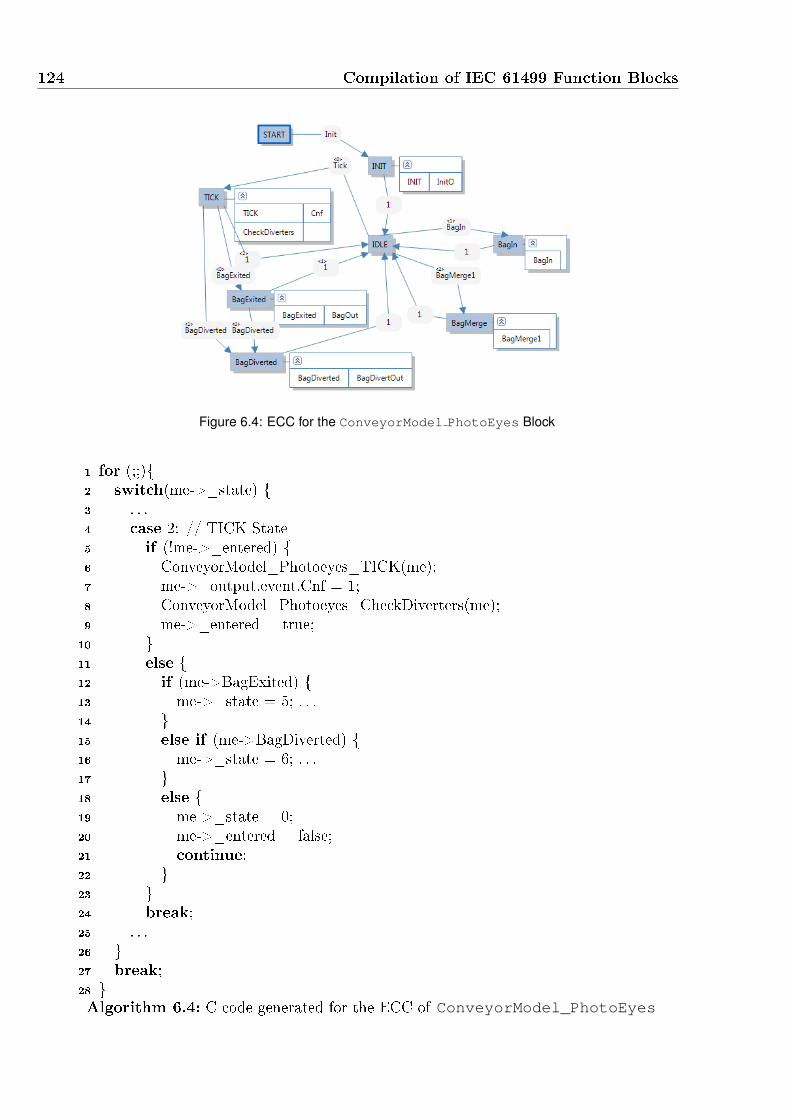
124 Compilation of IEC 61499 Function Blocks
Figure 6.4: ECC for the ConveyorModel PhotoEyes Block
1 for (;;){2 switch(me->_state) {3 . . .4 case 2: // TICK State5 if (!me->_entered) {6 ConveyorModel_Photoeyes_TICK(me);7 me->_output.event.Cnf = 1;8 ConveyorModel_Photoeyes_CheckDiverters(me);9 me->_entered = true;10 }11 else {12 if (me->BagExited) {13 me->_state = 5; . . .14 }15 else if (me->BagDiverted) {16 me->_state = 6; . . .17 }18 else {19 me->_state = 0;20 me->_entered = false;21 continue;22 }23 }24 break;25 . . .26 }27 break;28 }Algorithm 6.4: C code generated for the ECC of ConveyorModel_PhotoEyes

6.1 Compilation to C 125
Service Interface Function Blocks
Service interface function blocks are executed in the same way as other blocks, but as the
corresponding XML �les contain no executable speci�cation, executable code is generated
using pre-written templates instead. A number of service interface function blocks are
also prescribed in the standard [15], such as PUBLISH and SUBSCRIBE communication
blocks. During compilation, FBC identi�es the C implementations for known service
interface function blocks using a directory structure. The C implementations are manually
developed before compilation, following the same code structure as generated code, using
functions based on an FBType data structure. As such, the appropriate template �les for
a block are simply copied to the output directory.
FBC also allows for programmatic commands within the C code template, including
insertion of dynamic values into the templates and copying of addition �les. This allows
the compiler to generate multiple block implementations from a single C source �le. For
instance PUBLISH blocks have a variable number of ports, declared in the su�x of the
block type. Using this su�x (for example 1 for PUBLISH_1 and 5 for PUBLISH_5)
instance speci�c C �les are generated with structures and reactive functions with one and
�ve ports respectively.
6.1.2 Further FBC Development
The work from Yoong et al. did not generate code for IEC 61499 Adapters, and algorithms
not written in C code were generated as empty C functions. The original FBC was
therefore unable to compile the majority of IEC 61499 speci�cations developed with tools
that do not natively support algorithms written in C code. This thesis developed FBC
further to support HCECCs introduced in Chapter 4, adapters, and algorithms written
in Structured Text (ST).
HCECCs
Generation of C code for HCECCs was implemented by modifying several aspects of FBC.
Firstly, the compiler was modi�ed to parse the custom XML syntax created for HCECC
elements within a basic function block. Each custom XML element is handled by a
separate function to parse the required data. Synchronous C code is generated from an
internal representation for each HCECC by extending the algorithm that generates code
for basic function blocks. While Chapter 4 describes the IEC 61499 compatible equivalent
of HCECCs, for direct execution the semantics are implemented more e�ciently.
When using the FBC compiler, code for an HCECC is generated as a set of nested and
sequentially executed state-machines in a single reactive function. Because an HCECC
block contains multiple state-machines, as the block data structure is generated, extra

126 Compilation of IEC 61499 Function Blocks
_state and _entered variables are added, using a unique pre�x for each ECC. The
algorithm shown in Algorithm 6.5 is used to generate code for the HCECC. This function
replaces the generation of an ECC in the original GenerateBFB procedure used by FBC,
such that event-data associations and clearing of events is still handled in the same way.
1 procedure GenerateHCECC(hcecc)2 S := set of states in hcecc;3 PARA := set of HCECCs in parallel with hcecc;4 generate code to start an in�nite for loop;5 foreach s ∈ S do6 generate new case for s in switch-statement;7 if not entered then8 execute state actions;9 if state is re�ned then10 generate code to reset re�ning HCECC;11 end12 else13 foreach transition condition, t, of state s to next-state n do14 generate code to test for t and restart switch statement with state :=
n;15 if t is always true then16 break;17 end18 end19 end20 if state is re�ned then21 GenerateHCECC(state.re�ningHCECC);22 end23 generate code to exit the in�nite for loop;24 end25 generate code to end the in�nite for loop;26 foreach para ∈ PARA do27 GenerateHCECC(para);28 end29 end procedure
Algorithm 6.5: Algorithm to generate C code for an HCECC.
As an example, for the HCECC in Figure 6.5, GenerateHCECC creates a switch-case
statement for each state in the top level hcecc passed as an argument to the function (line
6). Each case statement checks if the executing block has already entered the state and if
not, it's algorithms are called, and outputs are emitted completing the tick for this ECC
(lines 7-12). In addition, if the state is re�ned, such as the Running state, the re�ning
ECC TickECC and any ECCs in parallel with the re�ning ECC are all initialised to state 0
and their state entered �ags are cleared (lines 9-11). If the state has already been entered,
exiting transitions are evaluated in order of their priorities (lines 13-18). If a transition is

6.1 Compilation to C 127
Figure 6.5: HCECC for Photo-Eye Simulator
taken, as with standard ECCs, the switch-case statement is restarted. This immediately
enters the new state, strongly aborting the execution of re�ned ECCs. If no transition
is taken, then nested ECCs are executed in the �xed order de�ned by the hierarchy and
parallel operators. For states which are re�ned, GenerateHCECC is called to generate
the code for the re�ning HCECC (line 21). Similarly, after any HCECC is printed, if it
has other HCECCs in parallel, they are also generated using GenerateHCECC (line 27).
In this way, the overheads of the equivalent composite function block are avoided by
executing the ECC product on the �y. The use of a single function block with a single copy
of each algorithm reduces the memory used by the speci�cation. By generating a single
reactive function instead of a set of reactive function for the composite function block
implementation, performance is also improved. Section 6.1.3 presents some performance
benchmarks, comparing HCECC with standard implementations of the same behaviour.
Translation of Structured Text
The IEC 61499 standard allows any language for algorithm speci�cation, but explicitly
mentions the IEC 61131-3 set of languages for backwards compatibility. Originally FBC
only accepted algorithms written in C, because of a lack of translation tools. This re-
striction made FBC incompatible with function block models developed with many IEC
61499 tools. FBDK [39] supports Structured Text, Ladder Logic Diagrams and Java
while 4DIAC [40] and nxtStudio [1] both currently only support Structured Text. In-
troducing translation of IEC 61131-3 Structured Text (ST) into C code therefore allows
speci�cations from other IEC 61499 tools to be compiled with FBC.
The translator was implemented based on a grammar for ST, and ANTLR [87] was
used to produce a parser and lexical analyser. The parser generates an abstract syntax

128 Compilation of IEC 61499 Function Blocks
tree from arbitrary ST code, and from this tree, C code is generated. The generation
of code follows the PLCOpen [69] semantics of structured text, creating semantically
equivalent and human-readable C code. The excerpt in Algorithm 6.6 is taken from the
conveyor model, which simulates the photo eye detection by comparing positions with the
bags on the conveyor. The generated C code is shown in Algorithm 6.7 and remains very
similar to the ST implementation due to the simple mapping of statements. To ensure
the evaluation order of expressions is maintained, brackets are added around all relational
and mathematical operators. An option was added to the translator to insert the required
pointer dereference for the instance data generated by FBC (the variable me).
1 (* Code Comment *)2 FOR pePtr := 0 TO PECount-1 DO3 FOR bagPtr := 0 TO 19 DO4 IF ( bagDSPos >= PEPositions[pePtr]) AND5 (bagUSPos <= PEPositions[pePtr]) THEN6 (* this PE needs to 'detect' *)7 PEDetects[pePtr] := TRUE ;8 EXIT;9 END_IF;10 END_FOR;11 END_FOR;
Algorithm 6.6: Sample ST code from Photo-Eye Simulator
1 /* Code Comment */2 for(pePtr = 0; pePtr <= me->PECount-1; pePtr++){3 for(bagPtr = 0; bagPtr <= 19; bagPtr++){4 if( (bagDSPos >= me->PEPositions[pePtr]) &&5 (bagUSPos <= me->PEPositions[pePtr]) ){6 /* this PE needs to 'detect' */7 me->PEDetects[pePtr] = true;8 break;9 }10 }11 }
Algorithm 6.7: Equivalent C code for Photo-Eye Simulator
When compiling a basic function block, if an algorithm is speci�ed using ST, FBC in-
vokes this parser to generate C code with the required pointer dereference. The generated
C code can then be copied directly into the C function corresponding to the algorithm,
in the same way that user written C code is inserted.
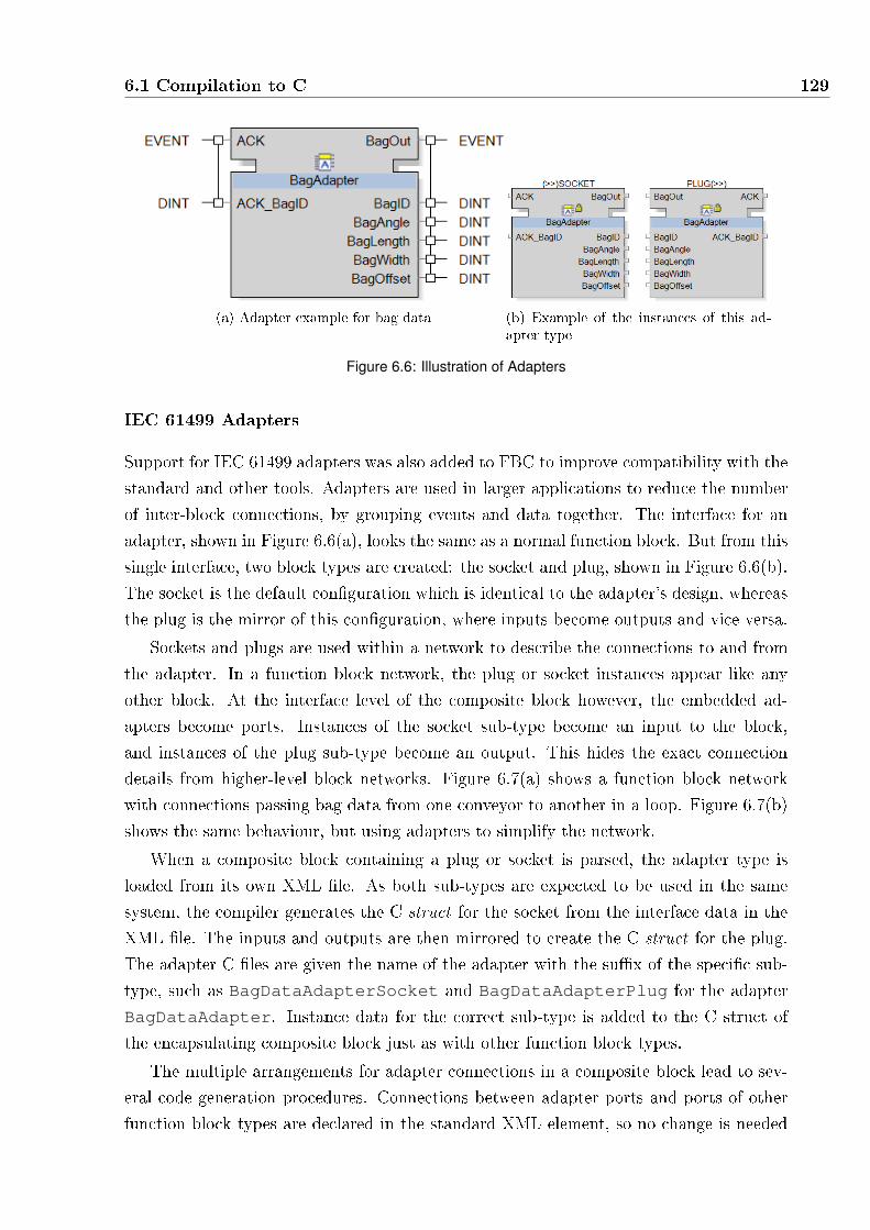
6.1 Compilation to C 129
(a) Adapter example for bag data (b) Example of the instances of this ad-apter type
Figure 6.6: Illustration of Adapters
IEC 61499 Adapters
Support for IEC 61499 adapters was also added to FBC to improve compatibility with the
standard and other tools. Adapters are used in larger applications to reduce the number
of inter-block connections, by grouping events and data together. The interface for an
adapter, shown in Figure 6.6(a), looks the same as a normal function block. But from this
single interface, two block types are created: the socket and plug, shown in Figure 6.6(b).
The socket is the default con�guration which is identical to the adapter's design, whereas
the plug is the mirror of this con�guration, where inputs become outputs and vice versa.
Sockets and plugs are used within a network to describe the connections to and from
the adapter. In a function block network, the plug or socket instances appear like any
other block. At the interface level of the composite block however, the embedded ad-
apters become ports. Instances of the socket sub-type become an input to the block,
and instances of the plug sub-type become an output. This hides the exact connection
details from higher-level block networks. Figure 6.7(a) shows a function block network
with connections passing bag data from one conveyor to another in a loop. Figure 6.7(b)
shows the same behaviour, but using adapters to simplify the network.
When a composite block containing a plug or socket is parsed, the adapter type is
loaded from its own XML �le. As both sub-types are expected to be used in the same
system, the compiler generates the C struct for the socket from the interface data in the
XML �le. The inputs and outputs are then mirrored to create the C struct for the plug.
The adapter C �les are given the name of the adapter with the su�x of the speci�c sub-
type, such as BagDataAdapterSocket and BagDataAdapterPlug for the adapter
BagDataAdapter. Instance data for the correct sub-type is added to the C struct of
the encapsulating composite block just as with other function block types.
The multiple arrangements for adapter connections in a composite block lead to sev-
eral code generation procedures. Connections between adapter ports and ports of other
function block types are declared in the standard XML element, so no change is needed

130 Compilation of IEC 61499 Function Blocks
(a) Network Without Adapters (b) Identical network using Adapters
Figure 6.7: Demonstration of Adapters
to generate code. Within function block networks, connections between pairs of adapters
are declared in a separate XML element which is also parsed into an internal represent-
ation. All types of adapter connections are examined by an extended EnsureAcyclic
function, ordering them similar to standard event and data connections. After an acyc-
lic execution order is found, code is generated for the two additional connection types:
connections between two adapters and connections between an adapter and port.
Adapter connections between a socket and a plug represent bi-directional communic-
ation, and therefore require two segments of code. Before the function block containing
the plug is executed, code is generated to update the input of the plug from the output
of the socket. Similarly, code is generated to update the input of the socket from the
output of the plug before for the function block containing the socket is executed. As
both segments of code cannot occur before each other, one segment of code will read the
delayed output values from the other block. The exact ordering is determined based on
the extended EnsureAcyclic function. In the case where no other connections exist
to force an execution order, one side of adapter connections will be arbitrarily delayed.
Connections between two adapters of the same sub-type occur when a composite block
just exposes an embedded socket or plug port to its own interface. Figure 6.8 illustrates
this behaviour, where the interface for Conveyor_Model contains plugs, pre�xed with
>> and sockets su�xed with >>. The adapter ports of Conveyor_Model are connected
to this block's interface, replicating the same plugs and sockets. In this scenario, data is
copied from inputs in the composite block's adapter to inputs of the embedded block's
adapter before the block is executed. After execution, output data from the block's
adapter is copied to the outputs of the composite block's adapter.
For connections from an adapter to a block input port, code is generated to update
the port with data from the output of the adapter before the block is executed. Similarly,
for connections from a block output port to an adapter, code is generated to update the

6.1 Compilation to C 131
Figure 6.8: Composite block with nested Adapter ports
input of the adapter after the block is executed.
6.1.3 Compiler Performance Results
To evaluate the impact of the changes, notably the addition of HCECCs, a suite of test
applications was used to compare both quantitative and qualitative factors. The test
applications, available from [88], di�er in the number of blocks used and the complexity
of algorithms, to provide a variety of implementations. HCECC implementations of each
application are compiled with the extended FBC compiler, FBC-HCECC, and compared
with ECC implementations using the research and academic de-facto standard FBRT [39],
the commercial and industry proven nxtFORTE [45] and the original FBC [30].
Table 6.1 shows the applications tested, with the quantities of function block network
and basic block design elements used. Unique blocks refers to the number of unique
function block types, as some examples such as the Water Monitor use multiple instances
of the same block. All other design elements are counted from these unique block types.
Connections are the number of event and data connections used in any function block
network. States and Transitions are the total number of states and transitions used in all
basic blocks. With the exception of the ConveyorController example, the ECC and
HCECC implementations for each application were developed independently according to
the requirements of the application. The ConveyorController was developed solely as
an HCECC, and then converted to a composite function block by applying the semantics
of each operator. For HCECCs re�ned states are recorded as one state plus the number
of states embedded within it.
In all of the examples, the number of states and transitions are the same or fewer in
the HCECC implementation. The operators given to HCECCs allow more behaviours to
be compressed into a single block, making them faster and easier to develop and maintain
for the same behaviour. The reduction in the number of blocks used for many of the
applications has the most signi�cant impact on the ease of development and maintenance

132 Compilation of IEC 61499 Function Blocks
Table 6.1: HCECC and ECC Size ComparisonECCs HCECC
Application Unique
Blocks
Connec-
tions
States Transi-
tions
Unique
Blocks
Connec-
tions
States Transi-
tions
Watch 3 21 17 24 1 0 14 20DistributionStation
2 18 10 12 1 0 10 12
Drill Station 2 10 9 10 1 0 9 9WaterMonitor
4 31 16 38 3 28 16 38
CruiseController
5 32 15 42 1 0 11 38
MP3Player 4 22 14 24 1 0 10 15ConveyorModel
3 25 11 19 1 0 11 15
ConveyorController 1
5 18 12 23 1 0 8 10
of an application. This is because a change in a single block's interface will result in
changes in the connections of the encompassing composite block, and possibly in the
connected blocks.
To compare performance, a test �le was generated for each application containing one
million pseudo-random input vectors. Each vector contains a random single event, as well
as random values for each data input. For each application, a test bench was developed
that is speci�c to each implementation. The results obtained exclude the time taken to ex-
ecute the test bench without the application under test. The run-times and synchronous
applications were executed on a dual-core 2.5Ghz PC, with 4GB RAM. The Java im-
plementation synthesized for FBRT by FBDK was compiled using javac from Oracle's
Java Development Kit 6 (JDK) [89] and executed using the included Java Virtual-Machine
(JVM) with default settings. nxtStudio's implementation was deployed to nxtForte ver-
sion 1.5. Because of the compilation and deployment method used by nxtStudio, the
object code size for nxtForte is approximated by using FORTE [40], the open source run-
time on which nxtForte is based. The C code from FBC and FBC-HCECC was compiled
using Visual Studio's [90] bundled C compiler, with the -O2 optimization switch.
Figure 6.9 shows the execution time for 1 million input event reactions for each applic-
ation. Due to the scale of the di�erences, a logarithmic scale is used. The values shown
on the graph were obtained by calculating the average after 10 consecutive runs of each
program. In order to negate the e�ects of caching and just in time compilation by Java,
the time for the �rst execution for each program was not used.
116 Controllers are used together in benchmarks to form a larger BHS example

6.1 Compilation to C 133
Figure 6.9: Test-bench Execution times
To better visualise the di�erences, the results were normalised in Figure 6.10 such that
FBC-HCECC has the value of 1, and the vertical scale is logarithmic because of the range
of results.
Figure 6.10: Normalised benchmark execution times compared to FBC-HCECC.
These results show that both synchronous approaches, FBC and FBC-HCECC, are
always faster than the two run-time approaches from FBRT and nxtForte. This is due to
the synchronous approach, which removes the need for complicated run time scheduling
of events. The FBC-HCECC implementation is between 1.5 and 8 times faster than
FBRT, and much faster than nxtForte, ranging from 32 to 177 times faster. Comparing
FBC using ECCs, and FBC-HCECC using HCECCs, it appears that the predominant
performance bene�t, comes from the reduction in the number of blocks that are used and
therefore executed. The FBC-HCECC implementation ranges from 1% faster in the large
BHS example, to over 2 times faster in the MP3Player application.
Figure 6.11 shows the size of the code produced by each approach for each application.

134 Compilation of IEC 61499 Function Blocks
The code synthesized by FBC is always smaller than FBRT, and even more so compared
with FORTE. FBC-HCECC extends this improvement, generating code that is smaller
than all other implementations. As with performance comparisons, this bene�t likely
arises from the smaller number of function blocks needed to represent the same behaviour.
The cruise controller example bene�ting the most, due to a reduction from �ve blocks
down to one.
Figure 6.11: Test-bench Object Code Size
To better visualise the di�erences, the same code size measurements are normalised in
Figure 6.12 such that FBC-HCECC has the value of 1. Ranging from 2 to 12 times the
size of code from FBC-HCECC, the results show the consistently larger code generated
by FORTE. Code from FBRT and FBC are comparatively similar, averaging 3.5 and 3
times larger than FBC-HCECC.
Figure 6.12: Normalised code size compared to FBC-HCECC
These experiments show that the reduction in complexity a�orded by HCECCs im-
proves IEC 61499 designs, making them simpler and more maintainable. The semantics

6.1 Compilation to C 135
of HCECCs also allow e�cient execution, such that while an HCECC re�ects a larger
IEC 61499 compliant speci�cation, direct compilation of HCECCs produces faster and
smaller code than alternative approaches.

136 Compilation of IEC 61499 Function Blocks
6.2 Compilation for Rockwell PLCs
The IEC 61131-3 set of languages intended to de�ne a uni�ed standard for the industrial
control languages: Structured Text (ST), Ladder Logic Diagrams (LLD), Instruction List,
Sequential Function Chart and IEC 61131-3 Function Block Diagrams (FBDs). PLC man-
ufacturers however, failed to agree on a single implementation, resulting in speci�cations
which are limited to a single manufacturer.
This work targets the popular range of PLCs from Rockwell Automation [23]. The de-
veloped compiler therefore assumes Rockwell execution semantics when translating func-
tion block components into ladder logic diagrams. It would also possible to generate
code for PLCs from other manufacturers, by modifying the output �le format and the
generated LLD instructions.
Rockwell's IDE for PLC programming, RSLogix [79] uses an XML format with the
extension L5X to represent the con�guration for a controller. The developed compiler,
called FB2L5X, generates a full L5X �le for a single controller from a IEC 61499 system
description. The generated L5X �le can be deployed and debugged using RSLogix.
6.2.1 Synchronous IEC 61499 to PLC Semantics
Recall from Chapter 5 that PLCs execute using the concept of a scan-cycle, identical to
the synchronous tick. This similarity allows generation of code for PLCs to follow the
approach used by FBC, creating a data structure and reactive function for each function
block.
Table 6.2 summarises the relationships between function block elements and equivalent
PLC design components. A device in IEC 61499 corresponds well with a PLC con�gura-
tion for a single controller. Similarly, resources are equivalent to a periodically executed
task. However, due to performance requirements it may be required to divide a single
resource into multiple tasks and programs. Additional con�guration is therefore required
to de�ne the allocation of blocks within a resource to various tasks, the next subsection
describes how this is achieved.
Rockwell Add-on Instructions are an extended form of an IEC 61131-3 routine that
includes instance data. They are utilised to implement the reactive function for each block
type, as well as basic function block algorithms. The associated instance data is used to
store the data structure for each instance of the block.
The data structure for each FBType is constructed using the same approach used
by FBC. Instead of C structures, the IEC 61131-3 equivalent User-De�ned Data types
(UDTs) are used. In the UDT for a block type, variables for the event and data interface
of the block are declared, with two copies of each data port for event-data associations.
An instance of this UDT is then passed by reference to all of the Add-on Instructions
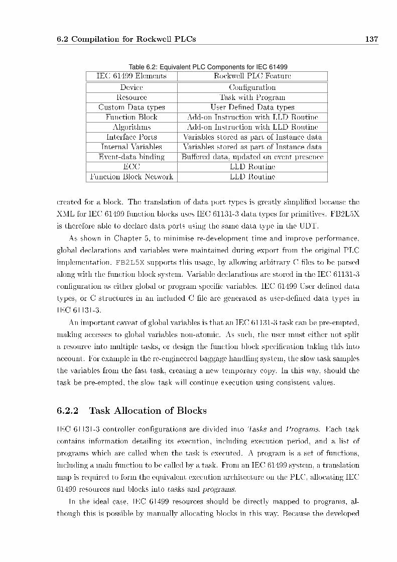
6.2 Compilation for Rockwell PLCs 137
Table 6.2: Equivalent PLC Components for IEC 61499IEC 61499 Elements Rockwell PLC Feature
Device Con�gurationResource Task with Program
Custom Data-types User De�ned Data-typesFunction Block Add-on Instruction with LLD RoutineAlgorithms Add-on Instruction with LLD Routine
Interface Ports Variables stored as part of Instance dataInternal Variables Variables stored as part of Instance dataEvent-data binding Bu�ered data, updated on event presence
ECC LLD RoutineFunction Block Network LLD Routine
created for a block. The translation of data port types is greatly simpli�ed because the
XML for IEC 61499 function blocks uses IEC 61131-3 data types for primitives. FB2L5X
is therefore able to declare data ports using the same data type in the UDT.
As shown in Chapter 5, to minimise re-development time and improve performance,
global declarations and variables were maintained during export from the original PLC
implementation. FB2L5X supports this usage, by allowing arbitrary C �les to be parsed
along with the function block system. Variable declarations are stored in the IEC 61131-3
con�guration as either global or program speci�c variables. IEC 61499 User de�ned data
types, or C structures in an included C �le are generated as user-de�ned data types in
IEC 61131-3.
An important caveat of global variables is that an IEC 61131-3 task can be pre-empted,
making accesses to global variables non-atomic. As such, the user must either not split
a resource into multiple tasks, or design the function block speci�cation taking this into
account. For example in the re-engineered baggage handling system, the slow task samples
the variables from the fast task, creating a new temporary copy. In this way, should the
task be pre-empted, the slow task will continue execution using consistent values.
6.2.2 Task Allocation of Blocks
IEC 61131-3 controller con�gurations are divided into Tasks and Programs. Each task
contains information detailing its execution, including execution period, and a list of
programs which are called when the task is executed. A program is a set of functions,
including a main function to be called by a task. From an IEC 61499 system, a translation
map is required to form the equivalent execution architecture on the PLC, allocating IEC
61499 resources and blocks into tasks and programs.
In the ideal case, IEC 61499 resources should be directly mapped to programs, al-
though this is possible by manually allocating blocks in this way. Because the developed

138 Compilation of IEC 61499 Function Blocks
controller block includes functions from both fast and slow tasks, it is necessary to split
up a resource for e�cient redeployment to a PLC. As global variables are used to com-
municate between the controller blocks originally sourced from the fast and slow tasks,
there are no connections between these blocks in the network for the controller resource.
This allows the compiler to split these components without a�ecting the behaviour.
To automate reallocation, a custom XML format is used to allow the user to map
function blocks and sets of global variables to programs, and programs to tasks. This
allows the compiler to open a complete IEC 61499 system, which may also include the
plant model, and only generate code for required function blocks. Global variables have
been allowed due to their use in the original IEC 61131-3 implementation, and in the
re-engineered BHS developed in Chapter 5.
Configuration
Global Variables
FastTask
FastProgram
MainRoutineRoutine1
Routine2
Routine3
Program Variables
Global C files
SlowTask
SlowProgram
MainRoutineRoutine1
Routine2
Routine3
Program Variables
Figure 6.13: Translation of IEC 61499 into IEC 61131-3
Figure 6.13 illustrates the con�guration for the BHS example. This con�guration
describes the mapping of the blocks within the controller resource into two tasks to ensure
that timing requirements can be met. Blocks from the controller resource which are
allocated to the Fast task execute once per 26 ms, while other blocks execute in the
slow task in the remaining execution time. These tasks communicate with each other
using global variables. Any additional C �les that are required must be speci�ed in the
con�guration �le, including whether they are to be generated as global or program-scoped
variables.
The following sections describe the generation of user de�ned data-types and reactive
functions for blocks networks and basic function blocks.
6.2.3 Generating UDTs for Function Blocks
An instance of the EncStateToEncCount block shown in Figure 6.14 is used for each
conveyor controller. It translates the output signal of the rotary encoder attached to the
conveyor section into a value representing the distance travelled by the conveyor belt.

6.2 Compilation for Rockwell PLCs 139
This block runs in the fast task of the controller, because at the belt's top speed the value
can change once every 26ms.
Algorithm 6.8 shows the L5X representation of the User De�ned Data-Type (UDT) for
the EncStateToEncCount block. Similar to the generation of C code by FBC, every
event and data port is created as a variable in a user de�ned data-type. The storage
element for input events is declared on line 3, then the input event, Req, is declared as
part of the element on lines 4-5. The input variable ConvID is declared on line 9, where
the pre�x `_' indicates that it is the interface copy. The internal bu�ered version, used
in algorithms and transition conditions is declared on line 10. Because the block contains
an ECC, the additional variables _state (line 17) and _entered (line 18) are added to
the UDT. For blocks with HCECCs, both of these variables are duplicated for each ECC,
using a unique pre�x for each ECC. Alternatively, for blocks containing a function block
network, instances of the required block types are declared in the UDT.
Figure 6.14: Encoder State to Encoder Count Block
6.2.4 Translating Block Networks
The current procedure for generating LLD for function block networks adopts the ori-
ginal approach used by FBC, where all inter-block communication is delayed until the
next tick. Algorithm 6.9 shows the procedure for generating code from a function block
network. Where all inputs are updated from outputs (lines 5-7), all blocks are executed
(lines 8-10), then all outputs are written (lines 11-13). This approach is the simplest to
implement, because execution of network blocks can be arbitrarily ordered with no con-
sequence to application behaviour. There is only a minor performance cost compared to
the instantaneous communication approach presented by FBC.
Figure 6.15 shows a part of the conveyor controller network used in the baggage
handling system. The L5X generated for the network is shown in Figure 6.10. The
Addon-Instruction begins with meta-data and input parameters (lines 1-9). The generated

140 Compilation of IEC 61499 Function Blocks
1 <DataType Name="EncStateToEncCountStruct" Family="NoFamily">2 <Members>3 <Member Name="_input" DataType="SINT" />4 <Member Name="Req" DataType="BIT"5 Target="_input" BitNumber="0" />6 <Member Name="_output" DataType="SINT" />7 <Member Name="Cnf" DataType="BIT"8 Target="_output" BitNumber="0" />9 <Member Name="_ConvID" DataType="INT" />10 <Member Name="ConvID" DataType="INT" />11 <Member Name="_EncoderIncr" DataType="INT" />12 <Member Name="EncoderIncr" DataType="INT" />13 <Member Name="_EncoderState" DataType="INT" />14 <Member Name="EncoderState" DataType="INT" />15 <Member Name="_EncCount" DataType="LINT" />16 <Member Name="EncCount" DataType="LINT" />17 <Member Name="_state" DataType="INT" />18 <Member Name="_entered" DataType="BOOL" />19 </Members>20 </DataType>
Algorithm 6.8: Encoder State Data Structure in L5X
1 procedure LLDGenerateNetwork(fb)2 IC := set of all connections to embedded block inputs;3 instances := set of all embedded block instances;4 OC := set of all connections to outputs of fb;5 foreach (source, destination) ∈ IC do6 generate code to assign destination to the value of source;7 end8 foreach (blockType, instanceData) ∈ instances do9 generate code to execute blockType with a reference to instanceData;10 end11 foreach (source, destination) ∈ OC do12 generate code to assign destination to the value of source;13 end14 end procedureAlgorithm 6.9: Algorithm for the compilation of function block networks into LLD
Rung 0 (lines 10-15), which sets the input event me.CONV0._input.Init, includes
a branch to enable the event on the presence of either me.START._output.WARM or
me.START._output.COLD. Because this is generated before the execution of the blocks,
this provides inputs with the value of outputs from the previous tick. Rungs 7-9 (lines
18-30) execute the Add-on Instructions for the three function blocks sequentially and in
an arbitrary order. As this network is within a resource, no code is generated for output
connections.

6.2 Compilation for Rockwell PLCs 141
Figure 6.15: Section of Conveyor Controller Network
6.2.5 Translating ECCs
Algorithm 6.11 shows the procedures used to generate LLD for the execution of a basic
function block, including either an ECC or HCECC. LLDGenerateBFB generates code
that clears previous output and input events (lines 7 and 13) and manages event-data
associations (lines 9-11 and 14-16). The LLDGenerateHCECC procedure, also shown in
Algorithm 6.11, is called on line 12 to produce code for the ECC or HCECC.
The HCECC or ECC generated by LLDGenerateHCECC uses an if-else statement
for each state. The in�nite for loop generated by FBC is instead created with start and
end labels around the if-else statements. This allows the execution to jump back to
the start when a new transition is taken, and jump to the end after a state has been
entered. As in FBC, the HCECC for a re�ned state is printed after the exiting transitions
are tested, and parallel HCECCs are printed after the END label of the original HCECC.
Figure 6.17 shows the LLD generated from the ECC in Figure 6.16, where the numbers
down the left-hand side indicate the rung number. Rung 0 clears the output events, and
Rung 1 updates the three variables associated with the input event REQ. Rungs 2-5 are
generated by LLDGenerateHCECC, with a single rung per state. The rung for each state

142 Compilation of IEC 61499 Function Blocks
1 <AddOnInstructionDefinition Name="DEV1Controller"2 CreatedBy="UoA\gsha041" >3 <Parameters>4 <Parameter Name="me" DataType="DEV1ControllerStruct"5 Usage="InOut" />6 </Parameters>7 <Routines>8 <Routine Name="Logic" Type="RLL">9 <RLLContent>
10 <Rung Number="0" Type="N">11 <Text>12 [XIC(me.START._output.WARM),13 XIC(me.START._output.COLD)]14 OTL(me.CONV0._input.Init)15 </Text>16 </Rung>17 ...18 <Rung Number="7" Type="N">19 <Text>E_RESTART(me.START)</Text>20 </Rung>21 <Rung Number="8" Type="N">22 <Text>23 ConveyorControllerParamatised_WithNetwork(me.CONV0)24 </Text>25 </Rung>26 <Rung Number="9" Type="N">27 <Text>28 ConveyorControllerParamatised_WithNetwork(me.CONV1)29 </Text>30 </Rung>31 ...32 </RLLContent>33 </Routine>34 </Routines>35 </AddOnInstructionDefinition>
Algorithm 6.10: Excerpt of generated controller network Add-on Instruction
Figure 6.16: ECC for Encoder State to Encoder Count
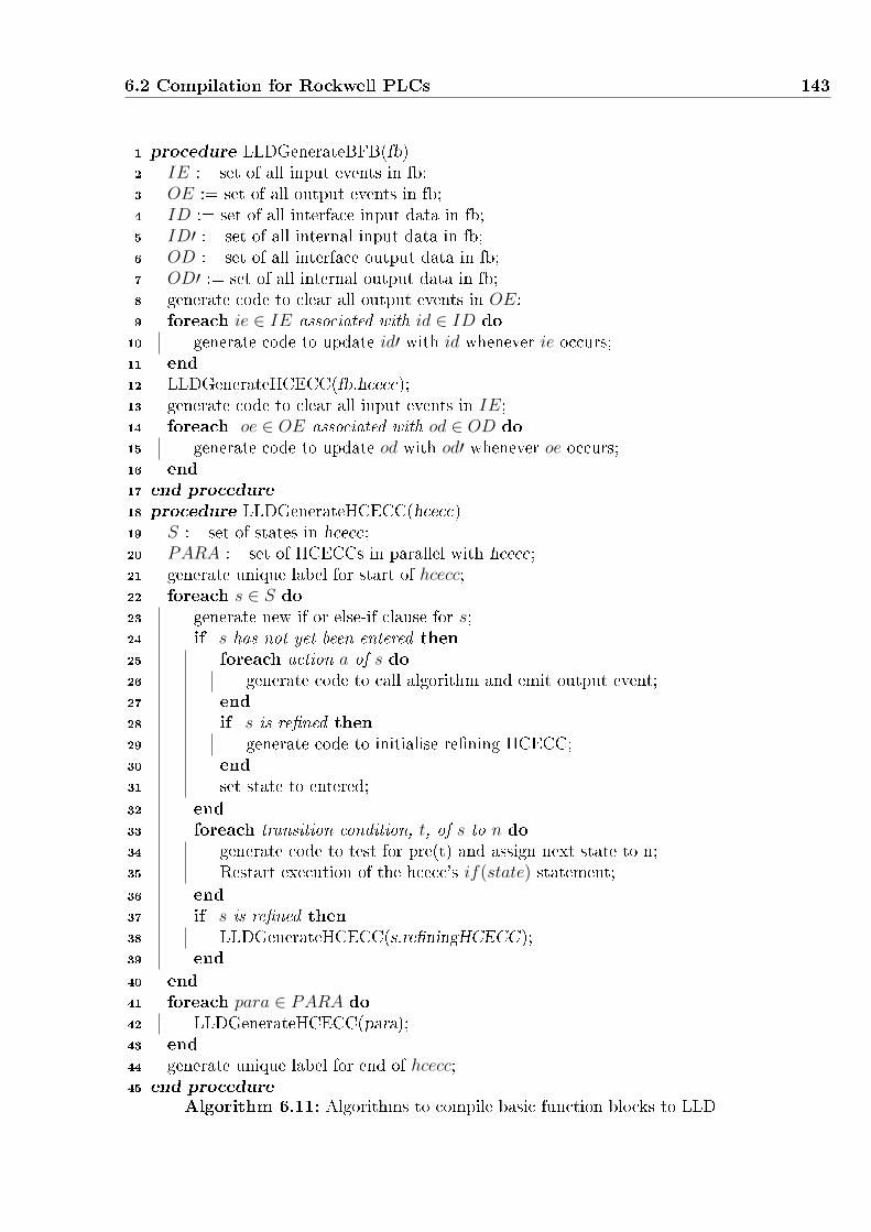
6.2 Compilation for Rockwell PLCs 143
1 procedure LLDGenerateBFB(fb)2 IE := set of all input events in fb;3 OE := set of all output events in fb;4 ID := set of all interface input data in fb;5 ID′ := set of all internal input data in fb;6 OD := set of all interface output data in fb;7 OD′ := set of all internal output data in fb;8 generate code to clear all output events in OE;9 foreach ie ∈ IE associated with id ∈ ID do10 generate code to update id′ with id whenever ie occurs;11 end12 LLDGenerateHCECC(fb.hcecc);13 generate code to clear all input events in IE;14 foreach oe ∈ OE associated with od ∈ OD do15 generate code to update od with od′ whenever oe occurs;16 end17 end procedure18 procedure LLDGenerateHCECC(hcecc)19 S := set of states in hcecc;20 PARA := set of HCECCs in parallel with hcecc;21 generate unique label for start of hcecc;22 foreach s ∈ S do23 generate new if or else-if clause for s;24 if s has not yet been entered then25 foreach action a of s do26 generate code to call algorithm and emit output event;27 end28 if s is re�ned then29 generate code to initialise re�ning HCECC;30 end31 set state to entered;32 end33 foreach transition condition, t, of s to n do34 generate code to test for pre(t) and assign next state to n;35 Restart execution of the hcecc's if(state) statement;36 end37 if s is re�ned then38 LLDGenerateHCECC(s.re�ningHCECC);39 end40 end41 foreach para ∈ PARA do42 LLDGenerateHCECC(para);43 end44 generate unique label for end of hcecc;45 end procedure
Algorithm 6.11: Algorithms to compile basic function blocks to LLD

144 Compilation of IEC 61499 Function Blocks
Figure 6.17: LLD for Encoder State to Encoder Count ECC
contains a branch with two sub-rungs for the �rst and subsequent entries into each state.
Where the instruction entered ]/[ tests the state has not yet been entered, and entered ] [
tests that it has already been entered. Finally, Rung 6 clears the input events and Rung
7 updates the variable associated with the output event CNF.
When a state is �rst entered (]/[ entered), the algorithms are called as separate Add-on
Instructions, and output events are set to true and the entered �ag is set to true ((L)
entered). After the state has been entered (] [ entered), the sub-rung with exiting
transitions will be processed in the next tick or scan-cycle. When a state has multiple
exiting transitions, each transition is generated as a new sub-rung within the nested

6.3 Discussion 145
branch. Evaluated in sequence, the �rst transition to match the conditions updates the
state variable, clears the entered �ag ((U) entered), and enters the new state by �rst
jumping to ECCStart.
For the case where the current state is ESREQ (_state is 1), shown in Rung 4, upon
entry to the state, the add-on instruction for the NAV_PEF algorithm is called, using the
same reference pointer me. The output event CNF is emitted, then the _entered �ag
is set and the execution of the ECC for this scan-cycle stops by jumping to the end. In
subsequent scan-cycles, the input event REQ is tested. If present, the state is set to 1,
the entered �ag is cleared, and the execution jumps back to the start to enter the ESREQ
state.
Algorithm Translation
Algorithms within basic function blocks are generated as additional add-on instructions
to be called by the add-on instruction of the HCECC. To ensure uniqueness through the
whole system, add-on instructions for a block use the name of the block type as a pre�x
to the algorithm name. FB2L5X currently only supports generating code for algorithms
written in C. C algorithms are translated using a parser written using ANTRL [87],
and LLD is generated in the L5X XML format following Rockwell's semantics. Every C
statement and several standard C functions, such as memset and memmov, have one-
to-one mappings within LLD. These mappings are hard-coded within the compiler, and
LLD is directly emitted when a mapping exists. For C functions without a direct LLD
equivalent, code is generated without the function call, but an error message is shown.
6.3 Discussion
The open XML format and platform independence of the IEC 61499 standard simpli�es
code generation and enables multiple execution targets from a single speci�cation. These
compilers allow a single IEC 61499 speci�cation to be executed either on a platform that
supports C code or on Rockwell PLCs currently in use by industry. This improves system
development, as developers can functionally test code before implementation, ensuring
that software functions according to speci�cations before the hardware system is built.
In this work the synchronous semantics have been adopted to allow for the generation of
directly executable code, improving execution performance. Direct execution also provides
the ability to target more platforms without the need for a pre-compiled run-time.
Speci�cations using HCECCs with the updated FBC compiler have signi�cant perform-
ance advantages over not only run-time approaches, but also the original FBC compiler.
Instead of �attening an HCECC into a collection of basic function blocks, executing
the ECC product on the �y reduces performance and memory overheads. The addi-

146 Compilation of IEC 61499 Function Blocks
tion of support for structured text algorithms and adapters into FBC makes it almost
fully compatible with the standard, and other IEC 61499 tools. Additional work on the
interoperability of the FBC compiler is also presented in Chapter 7.
IEC 61499 with HCECCs aid the development of complex and reliable systems, and
FB2L5X allows manufacturers to utilise the new standard for design and testing on a PC
before implementation on a PLC. FB2L5X currently lacks support for service interface
function blocks and adapters, due to its early development status. Support for such fea-
tures can be added in the future following the approach used by FBC. The generated PLC
con�guration will therefore need to be manually modi�ed to include routines which con-
nect hardware input and outputs with the function block network. Because the controller
used in this case study was re-engineered from an original LLD implementation, the ori-
ginal LLD code can be imported to implement this as well as inter-device communication
protocols.
Despite the resulting non-compliance with the IEC 61499 standard, global variables
have been allowed in applications such as the BHS case study due to the data intensive
nature of such speci�cations, and the importance of execution performance. Refer to
Chapter 5 which discussed some alternatives to the current usage of global variables. Both
compilers support the use of global variables by including or translating �les containing
de�nitions of global variables written in C code.

7Development of IEC 61499 Tools
The lack of mature software and hardware technologies supporting the standard make
development using function blocks more di�cult. To fully utilise IEC 61499 for the
development of complex systems, user friendly tools are required to encourage its use.
The standard is now in the beginning of its industrial uptake, currently supported by two
major industrial software vendors; ISaGRAF [16] and nxtControl [24], and a number of
hardware platforms, including SIEMENS, Beckho�, Wago and Advantech.
However, as presented in Chapter 2, IEC 61499 run-times, such as nxtForte used
by nxtControl, are non-deterministic and use bu�ers for event propagation. In some
function block network topologies, event bu�ers may also over-�ow and lead to lost events
and incorrect behaviour. This makes the development of reliable software very di�cult.
The synchronous function block compiler, FBC [30], on the other hand, provides e�cient
deterministic execution for function block applications, without the above problems. The
generation of C code then allows an application to be cross-compiled for many embedded
platforms.
In this chapter, the FBC compiler (Chapter 6) is extended and integrated into an ex-
isting commercial function block IDE, nxtStudio, as well as a new IDE called TimeMe.
Integration with nxtStudio will give users of the FBC compiler access to unique IEC 61499
based HMI blocks for the design of graphical human-machine-interfaces. Using HMI blocks,
users can graphically create visualisations for function block applications. Integration will
also allow nxtStudio users the option to deploy to nxtControl's nxtForte run-time or to
147

148 Development of IEC 61499 Tools
generate directly executable code depending on the target platform. The TimeMe IDE,
developed by the University of Auckland [91], was designed with FBC as the core tool for
IEC 61499 code generation. Because of the connection with the semantics used by the
FBC compiler, HCECCs are also supported. Co-development of both FBC and TimeMe
also allowed the implementation of a visual simulation mode for IEC 61499.
This chapter is organised as follows: Section 7.1 presents the integration of the compiler
into nxtStudio, along with the implementation of extra functionality to interface with
some of nxtControl's unique features. Section 7.2 presents an introduction to TimeMe
followed by the implementation of a simulation interface for synchronous function block
applications.
7.1 Integration with nxtStudio
nxtStudio [1] from nxtControl [24] is a leading commercial IDE for the IEC 61499 stand-
ard. Through a relationship with nxtControl, the University of Auckland has been working
to integrate the synchronous function block compiler into nxtStudio. This introduces the
bene�ts of the synchronous semantics for IEC 61499 into the commercial IDE and allows
complete model-view-controller design [11] for deterministic function block applications.
As a corollary, increasing the exposure of FBC could potentially lead to favorable changes
in the IEC 61499 standard, in particular, a well-de�ned and deterministic execution se-
mantics.
nxtStudio began development in 2007 and o�ers a very easy to use interface for the
development of all function block types. The IDE is bundled with nxtControl's function
block runtime nxtForte and features a graphical interface allowing the IDE to also
deploy to remote instances of the runtime. nxtStudio is also able to automate aspects
of re-mapping application components to di�erent devices, automatically inserting the
required service interface function blocks for communication.
An exceptional feature of nxtStudio is the integrated designer for component visual-
isations and human-machine-interfaces. Using a custom HMI block, a user describes the
information �ow between function block systems and their visualisation. In a separate
view for the same block, the user can graphically design the visualisation of the compon-
ent and write C# code to control its behaviour. When the HMI block is deployed, the
visualisation, which can be executed on a Windows PC, connects to the run-time using a
custom protocol to send and receive data.
Using nxtStudio the complete M.V.C. of a component can be developed and deployed.
Integration of FBC into nxtStudio then allows e�cient and deterministic implementation
of the function block applications on a wide range of targets. A plugin was developed,
providing a graphical interface for generating C code using FBC from within nxtStu-

7.1 Integration with nxtStudio 149
dio. Changes were made to FBC to support nxtStudio projects and many of the service
interface function blocks that nxtControl provides in the base nxtStudio library. The
generated C code can then be compiled for any platform.
7.1.1 Plugin Development
The plugin shown in Figure 7.1 was developed by another PhD Student at the University
of Auckland to provide an interface for the FBC complier. The plugin, launched from
within nxtStudio, allows the user to use FBC to generate C code and use Visual Studio
tools to compile the code into an executable. The Compile button calls FBC in order
to generate C code for the currently open function block or system. Make is used to
compile the code for execution on a 32bit x86 processor using the C compiler provided
by Visual Studio 2010 [90]. This executable will run on any Windows machine. Linux
is also supported by manually running a di�erent make �le which is also generated by
FBC. Run then launches the resulting executable, allowing quick testing on a PC, similar
to using nxtStudio to deploy to a local instance of the nxtForte run-time.
The options ccode, run and acyc are appropriate for all applications within nxtStu-
dio, but other FBC features are exposed to the user for completeness. C code is almost
solely used by the plugin, because the work on integration of nxtStudio speci�c features
presented in the following subsections were only implemented in C code. The run option
generates code for the function block application, as well as a main function which calls
the reactive function in a tight loop. This code can then be compiled and deployed on
the desired processor. acyc automatically removes causal event-loops by automatically
introducing a delay in one of the connections.
Figure 7.1: nxtStudio Plugin Interface for the FBC Synchronous Compiler
The remainder of this section explains the changes made to FBC as part of this thesis

150 Development of IEC 61499 Tools
to support compilation from nxtStudio projects, including implementation of nxtStudio's
HMI and inter-resource communication protocols.
7.1.2 Compiler Development
To enable FBC to compile a nxtStudio IEC 61499 project, several proprietary formats
and protocols used by nxtControl needed to be implemented.
While the XML format of all standard function blocks is speci�ed, nxtStudio uses
some additional elements and attributes for many of its own custom functionalities. The
NameSpace attribute was also added by nxtStudio to help di�erentiate identical block
names from di�erent projects. This tag is currently ignored by the compiler, as only
applicable �le paths should be given to the complier.
Dynamic Service Interface Function Blocks
The most complicated change for nxtStudio support is the addition of custom tags and
naming conventions to de�ne service interface function blocks which have dynamically
re-sizable ports. This is used in several blocks, including some simple boolean function
blocks provided as part of a nxtStudio library. A user is also able to de�ne dynamic
service interface function blocks (SIFBs), by following a design pattern described in the
user manual. Graphically, dynamic SIFBs such as the ADD block pictured in Figure 7.2,
have an icon in the bottom right that allows the user to drag in order to resize instances
of the block.
Figure 7.2: Graphical Representation of a Dynamic Service Interface Function Block
Algorithm 7.1 shows the relevant part of the ADD block's XML syntax. An extra
Attribute node is added to the InterfaceList node, which indicates that the variable, in
this case CNT, can be resized. The numbers after the variable name indicate the maximum
and minimum values, 16 and 2 respectively, and a default value of 2 for the variable. Ports
can now use the variable by adding the su�x ${CNT} to the variable name.
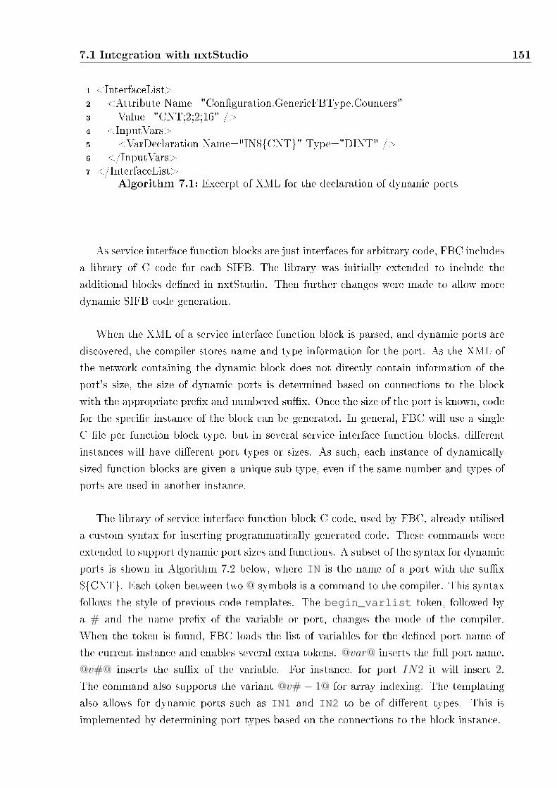
7.1 Integration with nxtStudio 151
1 <InterfaceList>2 <Attribute Name="Con�guration.GenericFBType.Counters"3 Value="CNT;2;2;16" />4 <InputVars>5 <VarDeclaration Name="IN${CNT}" Type="DINT" />6 </InputVars>7 </InterfaceList>
Algorithm 7.1: Excerpt of XML for the declaration of dynamic ports
As service interface function blocks are just interfaces for arbitrary code, FBC includes
a library of C code for each SIFB. The library was initially extended to include the
additional blocks de�ned in nxtStudio. Then further changes were made to allow more
dynamic SIFB code generation.
When the XML of a service interface function block is parsed, and dynamic ports are
discovered, the compiler stores name and type information for the port. As the XML of
the network containing the dynamic block does not directly contain information of the
port's size, the size of dynamic ports is determined based on connections to the block
with the appropriate pre�x and numbered su�x. Once the size of the port is known, code
for the speci�c instance of the block can be generated. In general, FBC will use a single
C �le per function block type, but in several service interface function blocks, di�erent
instances will have di�erent port types or sizes. As such, each instance of dynamically
sized function blocks are given a unique sub-type, even if the same number and types of
ports are used in another instance.
The library of service interface function block C code, used by FBC, already utilised
a custom syntax for inserting programmatically generated code. These commands were
extended to support dynamic port sizes and functions. A subset of the syntax for dynamic
ports is shown in Algorithm 7.2 below, where IN is the name of a port with the su�x
${CNT}. Each token between two @ symbols is a command to the compiler. This syntax
follows the style of previous code templates. The begin_varlist token, followed by
a # and the name pre�x of the variable or port, changes the mode of the compiler.
When the token is found, FBC loads the list of variables for the de�ned port name of
the current instance and enables several extra tokens. @var@ inserts the full port name.
@v#@ inserts the su�x of the variable. For instance, for port IN2 it will insert 2.
The command also supports the variant @v# − 1@ for array indexing. The templating
also allows for dynamic ports such as IN1 and IN2 to be of di�erent types. This is
implemented by determining port types based on the connections to the block instance.

152 Development of IEC 61499 Tools
1 // Template Source Code:2 @begin_varlist#IN@3 me->_OUT[@v#-1@] = me->_@var@;4 @end_varlist@5
6 // Generated Code:7 me->_OUT[0] = me->_IN1;8 me->_OUT[1] = me->_IN2;Algorithm 7.2: Excerpt C code in FBC's service interface function block library
HMI Communication Protocol
Integration with visualisations developed within nxtStudio is very bene�cial for fast
function block development using the model-view-controller design pattern. nxtStudio
provides two blocks for Human-Machine-Interface (HMI) speci�cation, one for visual
design with a block interface and another for connection to the rest of the function block
network.
(a) CAT Block Structure (b) Visual Editor for HMI Block
Figure 7.3: Human-Machine-Interface design elements in nxtStudio
• The CAT or Composite Automation Type block is similar to a standard com-
posite function block, but it encapsulates the de�nition of an HMI block as shown in
Figure 7.3(a). The HMI block is instantiated within the function block network of
the CAT to connect the visual component with standard function block components.
• The HMI block, is a customised function block similar to a SIFB that can only be
used within a CAT block. This block de�nes the interface for inputs and outputs
to the visual representation of the component. Like a standard service interface
function block, the HMI block can contain arbitrary code, but nxtStudio presents
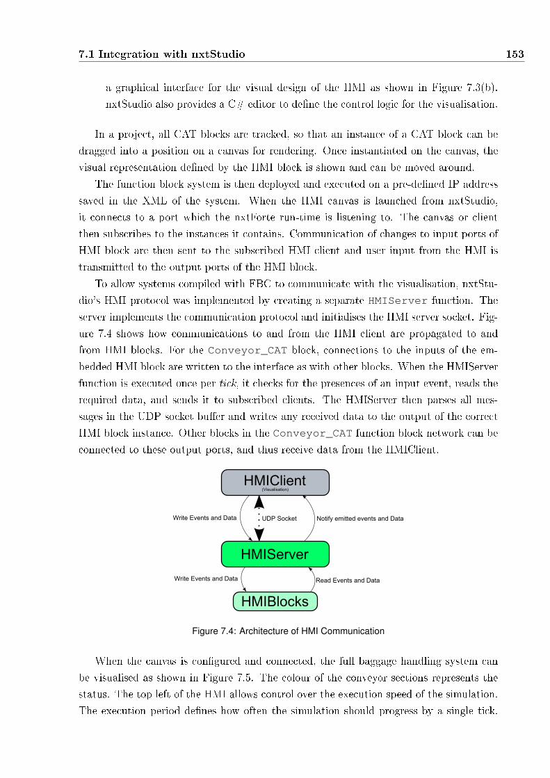
7.1 Integration with nxtStudio 153
a graphical interface for the visual design of the HMI as shown in Figure 7.3(b).
nxtStudio also provides a C# editor to de�ne the control logic for the visualisation.
In a project, all CAT blocks are tracked, so that an instance of a CAT block can be
dragged into a position on a canvas for rendering. Once instantiated on the canvas, the
visual representation de�ned by the HMI block is shown and can be moved around.
The function block system is then deployed and executed on a pre-de�ned IP address
saved in the XML of the system. When the HMI canvas is launched from nxtStudio,
it connects to a port which the nxtForte run-time is listening to. The canvas or client
then subscribes to the instances it contains. Communication of changes to input ports of
HMI block are then sent to the subscribed HMI client and user input from the HMI is
transmitted to the output ports of the HMI block.
To allow systems compiled with FBC to communicate with the visualisation, nxtStu-
dio's HMI protocol was implemented by creating a separate HMIServer function. The
server implements the communication protocol and initialises the HMI server socket. Fig-
ure 7.4 shows how communications to and from the HMI client are propagated to and
from HMI blocks. For the Conveyor_CAT block, connections to the inputs of the em-
bedded HMI block are written to the interface as with other blocks. When the HMIServer
function is executed once per tick, it checks for the presences of an input event, reads the
required data, and sends it to subscribed clients. The HMIServer then parses all mes-
sages in the UDP socket bu�er and writes any received data to the output of the correct
HMI block instance. Other blocks in the Conveyor_CAT function block network can be
connected to these output ports, and thus receive data from the HMIClient.
Write Events and Data Read Events and Data
Write Events and Data Notify emitted events and DataUDP Socket
HMIBlocks
HMIClient(Visualisation)
HMIServer
Figure 7.4: Architecture of HMI Communication
When the canvas is con�gured and connected, the full baggage handling system can
be visualised as shown in Figure 7.5. The colour of the conveyor sections represents the
status. The top left of the HMI allows control over the execution speed of the simulation.
The execution period de�nes how often the simulation should progress by a single tick.

154 Development of IEC 61499 Tools
The ’Progress Time By’ input allows the user to specify the time elapsed between
ticks. Together, these inputs allow the user to control the simulation speed relative to
real time. The MCP or Main Control Panel button in the top right provides the user
with controls over the system such as emergency stop, start and reset.
Figure 7.5: HMI Visualisation of a simple Baggage Handling System
An interface to the three bag sources is also shown at the top of the HMI canvas. The
name string is set at compile time, and includes the ID of the conveyor the bag will enter.
The bag source for conveyor 101 is automatic, and will continue to add non-overlapping
bags while enabled. The other bag sources are manual, allowing the user to add a bag at
any time with a given length but �xed width.
Upon entering a value for the bag length and clicking ’Add Custom’ within the '201
Source' input section, the HMI client sends a packet of data to the HMIServer. The packet
contains the full instance name of the block, in this case RES0.BagSourceLine2, and
the included data and an identi�er for which event was sent. The HMIServer function
parses this data, and set the outputs of the correct block instance. In the next tick, the
connected conveyor plant model block will receive this data and add a new bag to its
model.
Inter-resource Communication
As a mature IEC 61499 development environment, nxtStudio is able to automatically
insert service interface function blocks for communication when an application is distrib-
uted to separate resources. A group of blocks can be selected and the target device and
resource can be changed to a resource on another device. In the case of the baggage hand-
ling system, Figure 7.6 shows the re-mapping of parts of the application from one resource
to another. When a system is compiled for deployment, nxtStudio generates a separate
system �le which includes extra blocks which communicate events and data between re-
sources. This allows simple re-distribution of function blocks for di�erent deployment
scenarios.

7.1 Integration with nxtStudio 155
Figure 7.6: Redistributing some Conveyors within the Baggage Handling System example
Figure 7.7 shows the extra blocks added by nxtStudio. A resource may contain multiple
CommChannel blocks, as they send data to a single remote resource. As all incoming data
is sent to a single listening socket per resource, there is only one CommChannelUDPRecv
block. The LINKPUBLISHER block is used to send a packet of event and data values.
On the receiving side of a channel, events and data are separated into EVENTRECEIVER
and DATARECEIVER. Importantly, there are no connections between the Communication
Channel blocks and the related publish and receive blocks. The developed synchronous
compiler plugin for nxtStudio, passes the deployment system, with explicit communication
blocks, to the compiler.
Incoming Channel
Outgoing Channels
Receive from a ChannelPublish to a Channel
Figure 7.7: Communication Blocks Automatically Inserted by nxtStudio
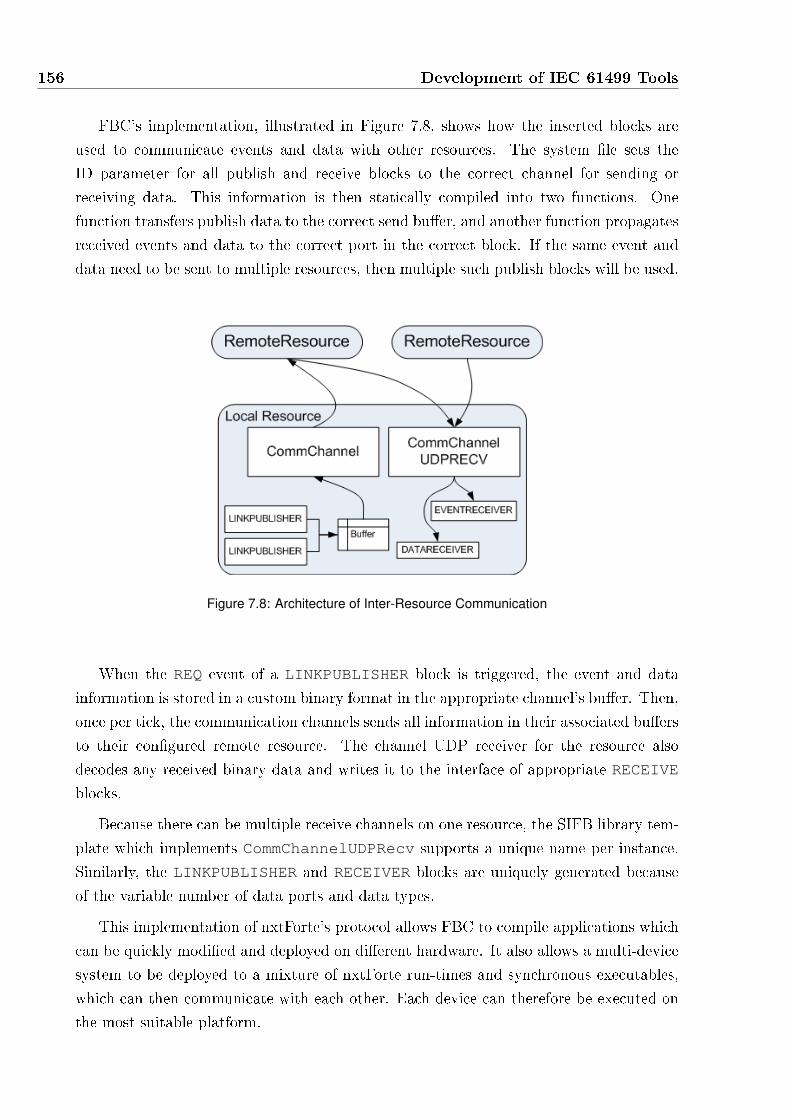
156 Development of IEC 61499 Tools
FBC's implementation, illustrated in Figure 7.8, shows how the inserted blocks are
used to communicate events and data with other resources. The system �le sets the
ID parameter for all publish and receive blocks to the correct channel for sending or
receiving data. This information is then statically compiled into two functions. One
function transfers publish data to the correct send bu�er, and another function propagates
received events and data to the correct port in the correct block. If the same event and
data need to be sent to multiple resources, then multiple such publish blocks will be used.
Figure 7.8: Architecture of Inter-Resource Communication
When the REQ event of a LINKPUBLISHER block is triggered, the event and data
information is stored in a custom binary format in the appropriate channel's bu�er. Then,
once per tick, the communication channels sends all information in their associated bu�ers
to their con�gured remote resource. The channel UDP receiver for the resource also
decodes any received binary data and writes it to the interface of appropriate RECEIVE
blocks.
Because there can be multiple receive channels on one resource, the SIFB library tem-
plate which implements CommChannelUDPRecv supports a unique name per instance.
Similarly, the LINKPUBLISHER and RECEIVER blocks are uniquely generated because
of the variable number of data ports and data types.
This implementation of nxtForte's protocol allows FBC to compile applications which
can be quickly modi�ed and deployed on di�erent hardware. It also allows a multi-device
system to be deployed to a mixture of nxtForte run-times and synchronous executables,
which can then communicate with each other. Each device can therefore be executed on
the most suitable platform.
7.2 TimeMe 157
7.1.3 FBC and nxtStudio Summary
With this level of compatibility with nxtStudio, the FBC synchronous compiler for IEC
61499 generates code to replace an instance of nxtForte. Because standard C code is
generated, it can be compiled into an executable for many platforms. FBC, therefore,
o�ers nxtStudio a compiler for generating deterministic code for safety critical or resource
constrained applications. Similarly, FBC bene�ts from a commercial tool for complete
model-view-controller component design. Fast re-distribution of the function block applic-
ation also improves development time, allowing less focus on the deployment architecture.
One caveat arises however, because users of nxtStudio expect event-triggered execution
semantics, whereas synchronous function blocks give di�erent behaviour to ECCs (see
Section 2.3.2). As such, the function block designer must be conscious of these di�erences
when designing ECCs which will be executed using FBC. HCECCs are also not supported,
making the description of complex behaviour more di�cult.
7.2 TimeMe
TimeMe Studio is an integrated development environment based on Microsoft Visual
Studio [90]. Developed at the University of Auckland [91], it aims to facilitate the design
of safety-critical embedded control systems by adopting a synchronous semantics for IEC
61499. IEC 61499 is utilised for component oriented design of distributed systems and the
synchronous semantics for function blocks provides the user with guaranteed determinism
and absense of deadlocks [34]. Because TimeMe was developed in house, it has allowed
complete control over feature development and tool integration.
The integration of the FBC compiler serves a vital role, allowing the execution of IEC
61499 speci�cations developed in TimeMe. Modifying the generated application allows
a customised IEC 61499 simulation for synchronous function block applications which
integrate with TimeMe's debug engine.
This Section explains the development and integration of FBC as an integral part of
TimeMe. The generation of an interactive tick-by-tick simulation application is intro-
duced enabling TimeMe to simulate models, similar to commercial synchronous design
environments such as Esterel Studio [92] and SCADE [13].
7.2.1 Integration of FBC
The compiler is integrated into TimeMe as part of the Visual Studio concept of a Project
Template. TimeMe introduces several project types which enable development of IEC
61499 applications, as shown in Figure 7.9. Each of the new templates automatically
initialise many of FBCs parameters for a particular purpose, focusing on the type of code

158 Development of IEC 61499 Tools
generated.
Figure 7.9: TimeMe Project Templates
Project parameters are propagated to Visual Studio's Con�gurations, which de�ne en-
vironment settings for the build process. TimeMe's con�gurations in the tool bar shown
in Figure 7.10, further con�gures TimeMe to call di�erent build tasks. The Run con-
�guration calls FBC with arguments to compile the currently open IEC 61499 �le and
generate the main function to run it. Simulation mode also calls the FBC compiler,
but with an argument which makes FBC generate code for an interactive simulation of the
current function block �le. More detail on simulation code follows in Sub-Section 7.2.2.
The other con�gurations use separate tools not covered in this work.
Figure 7.10: TimeMe Configuration Selection
Because TimeMe stores more information per function block than the standard XML
syntax allows, a custom XML �le is used to save and load function blocks. To use IEC
61499 standard tools, such as FBC, TimeMe generates standard XML �les for each �le
in the Project before invoking the tool.
During code generation, FBC traditionally printed status and error messages to the
console. To aid integration with Visual Studio's error and warning notice panel, an XML

7.2 TimeMe 159
format was de�ned to simplify parsing of these messages. The XML format is only printed
when FBC is called by another program. In both cases compilation notices are written
to stdout and errors are written to stderr. The messages are shown to the user
in the graphical form in Figure 7.11. Integration of messages allows completely hidden
compilation by FBC, and by including the name of the block causing the error, TimeMe
allows the user to double click on the message to open the block.
Figure 7.11: Code Generation Error Messages shown in TimeMe
When generating C code, FBC creates a Make�le and batch script which uses Visual
Studio's own nmake and cl, to compile the function block application. A Make�le for
GNU make is also generated for compilation to other targets using a compiler such as
gcc. For both run and simulation mode, the batch script is called by TimeMe to compile
the generated C code. This provides the user with a single button interface to create an
executable for any IEC 61499 application.
7.2.2 Implementation of Simulation Mode
TimeMe implements step-wise interactive simulation of IEC 61499 applications. This is
unique in the function block domain, but is similar to simulation in Esterel Studio [92]
and SCADE [13]. Visualisation and control of the simulated application is implemented
within TimeMe. While FBC generates an application for the user selected function block
model. The generated application connects to TimeMe and responds to commands with
the state of the simulated mode.
Figure 7.12 shows the simulation process in terms of interactions between TimeMe,
FBC and the simulated model. TimeMe calls FBC with a �ag to generate simulation
code. The generated code is then compiled using gcc or Visual Studio's C compiler, and
the resulting executable is launched. Upon execution, the simulation application connects
to the IDE using a TCP socket, sending information of the initial state. TimeMe then
provides the user with a graphical interface for controlling the execution, thus allowing
the user to progress to the next tick or stop the simulation, as required.
The two components communicate using a custom application level XML protocol,
allowing control requests from the IDE to the application, with detailed responses of
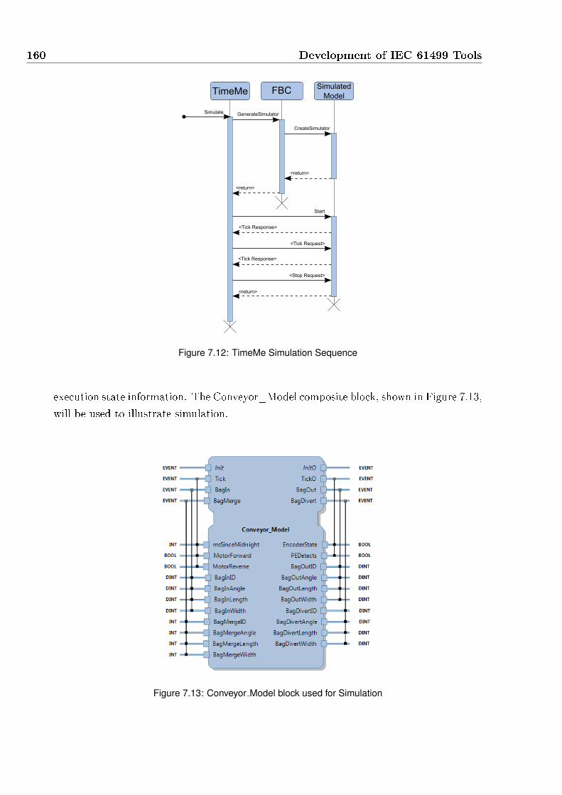
160 Development of IEC 61499 Tools
TimeMe FBCSimulated
Model
Simulate GenerateSimulator
CreateSimulator
<return>
Start
<Tick Response>
<Tick Request>
<Tick Response>
<Stop Request>
<return>
<return>
Figure 7.12: TimeMe Simulation Sequence
execution state information. The Conveyor_Model composite block, shown in Figure 7.13,
will be used to illustrate simulation.
Figure 7.13: Conveyor Model block used for Simulation
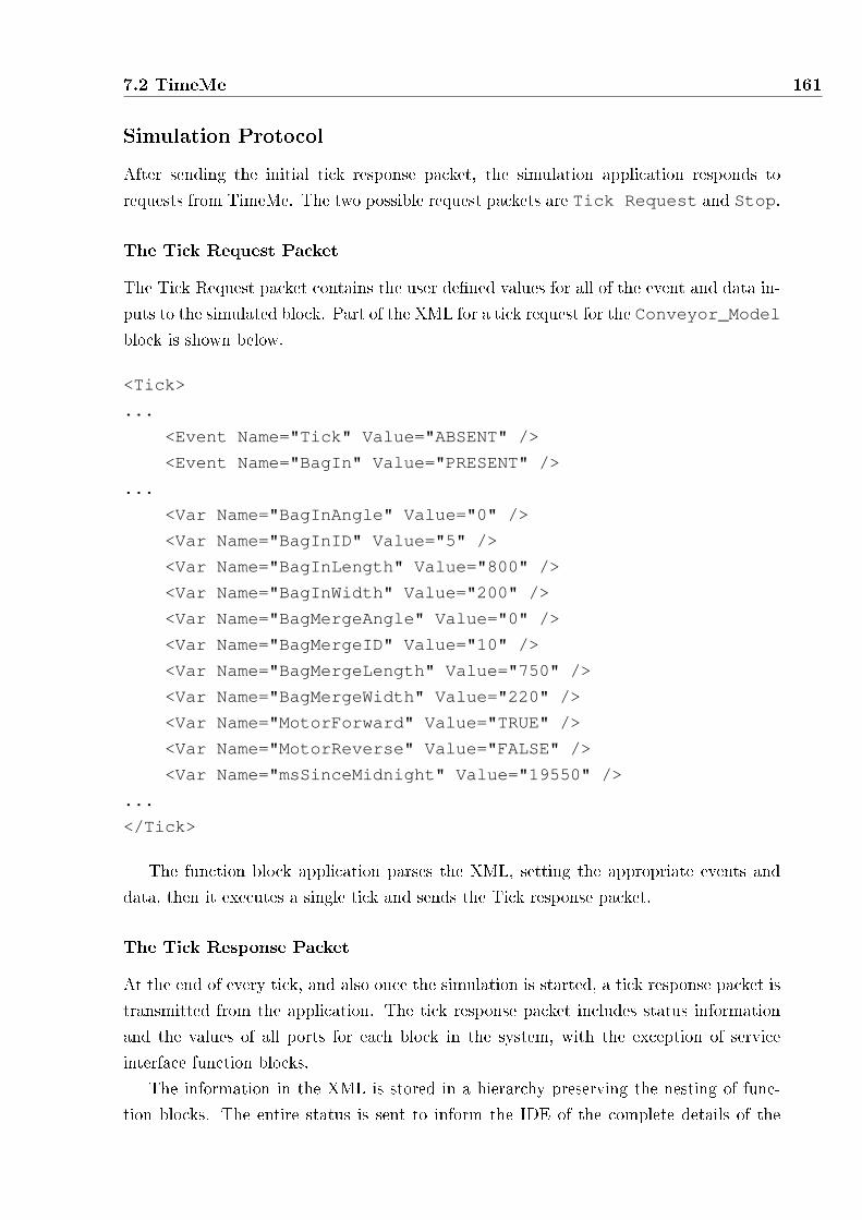
7.2 TimeMe 161
Simulation Protocol
After sending the initial tick response packet, the simulation application responds to
requests from TimeMe. The two possible request packets are Tick Request and Stop.
The Tick Request Packet
The Tick Request packet contains the user de�ned values for all of the event and data in-
puts to the simulated block. Part of the XML for a tick request for the Conveyor_Model
block is shown below.
<Tick>
...
<Event Name="Tick" Value="ABSENT" />
<Event Name="BagIn" Value="PRESENT" />
...
<Var Name="BagInAngle" Value="0" />
<Var Name="BagInID" Value="5" />
<Var Name="BagInLength" Value="800" />
<Var Name="BagInWidth" Value="200" />
<Var Name="BagMergeAngle" Value="0" />
<Var Name="BagMergeID" Value="10" />
<Var Name="BagMergeLength" Value="750" />
<Var Name="BagMergeWidth" Value="220" />
<Var Name="MotorForward" Value="TRUE" />
<Var Name="MotorReverse" Value="FALSE" />
<Var Name="msSinceMidnight" Value="19550" />
...
</Tick>
The function block application parses the XML, setting the appropriate events and
data, then it executes a single tick and sends the Tick response packet.
The Tick Response Packet
At the end of every tick, and also once the simulation is started, a tick response packet is
transmitted from the application. The tick response packet includes status information
and the values of all ports for each block in the system, with the exception of service
interface function blocks.
The information in the XML is stored in a hierarchy preserving the nesting of func-
tion blocks. The entire status is sent to inform the IDE of the complete details of the

162 Development of IEC 61499 Tools
current application state, and to avoid any communication until the next tick. Below
is an abbreviated Tick response XML packet, showing the structure of the XML, with
composite block instances containing the nested block instances. Basic function blocks
include information such as the current state, and the transition taken in the tick that
was just completed. If the basic block contains an HCECC, the XML will contain a list
of all current states and all transitions taken. Information from composite blocks consists
of event connections that are present and all of the data connections associated with each
present event.
<Tick>
<Instance Name="root" Type="Conveyor_Model">
<Events>
<Event Name="BagIn" Value="PRESENT" />
...
</Events>
<Vars>
...
<Var Name="BagInAngle" Value="0" />
<Var Name="BagInID" Value="5" />
<Var Name="BagInLength" Value="800" />
<Var Name="BagInWidth" Value="200" />
...
</Vars>
<Instances>
<Instance Name="BeltModel" Type="Conveyor_Belt_Model">
...
</Instance>
<Instance Name="PhotoEyeModel"
Type="Conveyor_PhotoEyes_Model">
<Events>
<Event Name="BagIn" Value="PRESENT" />
...
</Events>
<ECState Name="BagIn" />
...
</Instance>
</Instances>
<Connections>
<Connection Source="BeltModel.CNF"

7.2 TimeMe 163
Destination="PhototeyeModel.Tick" />
<Connection Source="BeltModel.EncoderState"
Destination="EncoderState" />
<Connection Source="BeltModel.EncCount"
Destination="PhototeyeModel.EncCount" />
</Connections>
</Tick>
The Stop Packet
Synchronous function block applications do not have an explicit termination, as they run
in an in�nite loop. The stop request, shown below, instructs the simulation application
to terminate, with no response sent to the IDE. TimeMe then reverts to the standard
function block view, with editing functionalities re-enabled.
<Stop />
Simulation Environment
When starting a simulation, TimeMe creates the input panel shown in 7.14 for the interface
of the block under test. This panel allows the user to set multiple events to be present,
and provide values for all data inputs.
Controlling the simulation adopts the standard debugging interface used by Visual
Studio, using the panel shown in Figure 7.15, to trigger simulation requests. The Start
button is used to start the simulation, and also to request another tick by creating the
tick request packet and sending it to the application. The Stop button sends the stop
request packet, and makes TimeMe exit simulation mode. The Restart Simulation button
stops and re-creates the simulation application in order to restart the debugging session.
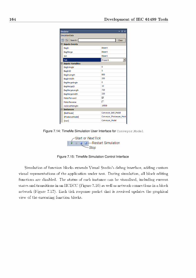
164 Development of IEC 61499 Tools
Figure 7.14: TimeMe Simulation User Interface for Conveyor Model
Figure 7.15: TimeMe Simulation Control Interface
Simulation of function blocks extends Visual Studio's debug interface, adding custom
visual representations of the application under test. During simulation, all block editing
functions are disabled. The status of each instance can be visualised, including current
states and transitions in an HCECC (Figure 7.16) as well as network connections in a block
network (Figure 7.17). Each tick response packet that is received updates the graphical
view of the executing function blocks.
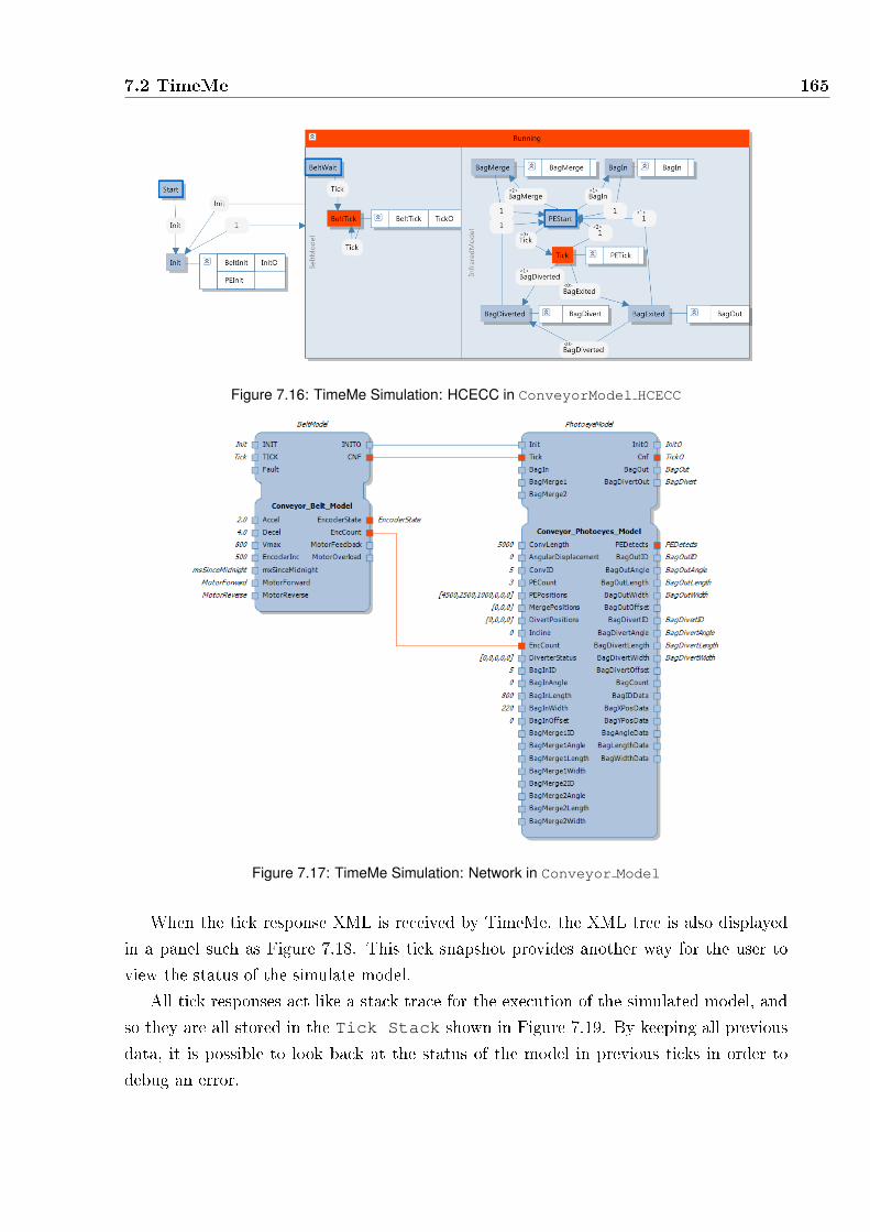
7.2 TimeMe 165
Figure 7.16: TimeMe Simulation: HCECC in ConveyorModel HCECC
Figure 7.17: TimeMe Simulation: Network in Conveyor Model
When the tick response XML is received by TimeMe, the XML tree is also displayed
in a panel such as Figure 7.18. This tick snapshot provides another way for the user to
view the status of the simulate model.
All tick responses act like a stack trace for the execution of the simulated model, and
so they are all stored in the Tick Stack shown in Figure 7.19. By keeping all previous
data, it is possible to look back at the status of the model in previous ticks in order to
debug an error.

166 Development of IEC 61499 Tools
Figure 7.18: TimeMe Tick Response XML Tree
Figure 7.19: TimeMe Tick Stack View
Simulation Application
Figure 7.20 shows the structure of the simulation application generated by FBC. A top
level XML node is passed to the simulated block, which adds its own XML node. Nested
blocks then add themselves to the XML node of their parent block. Each block also
has nodes for events and variables as well as block speci�c nodes for connections in the
case of a composite block, and states and transitions for basic blocks. This XML tree
remains constant during execution, with updates to attributes of static elements. Dynamic
elements, such as connections, states or transitions, which vary in quantity are re-added
to the XML tree each tick.
To read and write XML in C, the LGPL library mxml [93] is used, with two extra

7.2 TimeMe 167
Figure 7.20: Implementation of Function Block Simulation Application
functions to assist translating the common IEC 61131 data types to and from strings.
Every Tick Request from TimeMe the simulation application parses the XML and
sets the values of interface events and data. The tick function for the simulated block
is then called, with each block also updating it's XML attributes and dynamic elements.
Once all blocks have been executed, the XML tree is written to a bu�er and sent to
TimeMe.
When the Stop Request packet is received, the application just closes the socket
and terminates.
7.2.3 TimeMe Summary
Leveraging Visual Studio's well known interface, TimeMe presents an elegant user inter-
face for the design of synchronous function blocks with HCECCs. Tight integration with
FBC allows TimeMe to generate C code which can then be compiled for many target
platforms. The deterministic semantics and e�cient implementation from FBC provides
a signi�cant bene�t over alternative IEC 61499 development environments. Finally, the
inclusion of tick by tick simulation for any function block network enables complete o�-line
and in-depth testing, similar to several commercial IDEs for other languages.

168 Development of IEC 61499 Tools

8Conclusions
The bottom-up design of industrial and embedded systems is inadequate for the large and
complex systems of today. On its own, the IEC 61499 standard provides a component-
oriented language for model-driven engineering, simplifying design with graphical self-
documenting interfaces, networks and ECCs. The abstract event-triggered execution se-
mantics also simpli�es the reuse components on di�erent platforms. However, the execu-
tion semantics are informal and ambiguous. In addition, ECCs are unable to succinctly
describe complex behaviours. Yoong et al. [31] presented a signi�cant step towards the
use of IEC 61499 in safety-critical applications, by developing a formal synchronous se-
mantics for function blocks. However, the semantics presented challenges due to the use
of event-triggered ECCs to specify synchronous behaviour.
The goal of this thesis has therefore been to propose improvements to the IEC 61499
standard in order to develop complex and reliable automation and embedded systems.
This has been achieved by addressing the shortcomings of the standard with a new syn-
chronous semantics, and the development of tools for the use of IEC 61499. This chapter
summarises the contributions of this thesis and presents suggestions for future research.
169

170 Conclusions
8.1 Hierarchical and Concurrent ECCs for IEC 61499
8.1.1 Summary and Contributions
Two aspects of the IEC 61499 standard hinder the development of complex and reliable
systems. The ambiguous semantics of the standard are responsible for the variety of
incompatible implementations. Further, the use of a run-time to implement the event-
triggered semantics of the standard can in some implementations create non-deterministic
behaviour due to the dynamical scheduling of block execution and bu�ering of events. In
addition, to describe complex behaviours, ECCs require more states and transitions than
other graphical state-machines.
The synchronous semantics developed by Yoong et al. [31] address the �rst concern,
allowing deterministic and deadlock free execution of function block applications. As
a result, the synchronous semantics are also able to generate directly executable code,
which o�ers improved performance over run-time approaches. However, the proposed
semantics were also hindered by the use of ECCs, because simultaneous events could not
be monitored as they are not possible in the standard.
The primary motivation for previous ECC replacements was to address the ambiguous
semantics of the standard, and thus, to introduce a formalism for state-machine design.
As a result, the formalisms either fail to address the inadequacies of ECCs for exception
handling or complex speci�cation, or they do so at the expense of compatibility with the
standard.
Chapter 4 presented a new synchronous semantics for IEC 61499, with unique fea-
tures to address the de�ciencies in ECCs. The developed extensions, called hierarchical
and concurrent ECCs (HCECCs), adopt techniques from other graphical synchronous
languages, introducing state-machine re�nement and parallelism. With these additional
features, HCECCs improve the description of complex behaviour and allow simultaneous
events to be monitored while remaining compatible with the standard.
8.1.2 Future Work
The integration of more features from other Statecharts based languages, such as weak-
abortion, may be bene�cial. Also, a more intuitive mechanism for communication between
state-machines, potentially introducing instantaneous broadcast, would make HCECCs
more powerful. Such features were not introduced in this work due the the desire to
maintain compatibility with other IEC 61499 tools.

8.2 Reverse Engineering IEC 61131-3 into IEC 61499 171
8.2 Reverse Engineering IEC 61131-3 into IEC 61499
8.2.1 Summary and Contributions
As IEC 61499 is designed as a replacement for IEC 61131-3, it is possible to describe the
same applications in the newer standard. While the new standard o�ers many bene�ts,
industrial manufacturers are likely to delay adoption as redesigning a system from scratch
is time-consuming and it means that previous design e�ort in IEC 61131-3 is lost.
Related work such as [61, 70, 72] present approaches which re-create the semantics
of IEC 61131-3 languages as networks of function blocks. This leads to an application
that is harder to maintain than an original IEC 61499 implementation, as it will consist
of additional function blocks or states which manage semantic di�erences between the
implementation. Although approaches similar to this would allow arbitrary distribution
of the resulting function block network, it is unlikely that distribution would be desirable
at the level of a single routine.
In contrast, Dai et al. [73, 81] o�ers an approach which re-creates an IEC 61131-
3 application in IEC 61499 by following a class-oriented instead of component-oriented
architecture. After a solely manual translation, the class-based architecture removes the
need for global variables, as all of the required functions for a task are encapsulated in a
single block. This approach does not take full advantage of ECCs for design, but would
allow all IEC 61131-3 code to be reused as algorithms within a basic function block. As
a single component is divided into many functional classes, the approach is not suited for
model-view-controller design.
Chapter 5 presents a technique for the re-engineering of IEC 61131-3 applications into
IEC 61499 that reduces the time-cost by maintaining aspects of the legacy implementa-
tion. A tool has been developed which allows the automatic translation of IEC 61131-3
routines (designed in Rockwell's RSLogix 5000 IDE) into C functions for use in a function
block design. An approach is then presented for the development of a function block
component architecture, which then utilises the generated C code. Together, this allows
for a fast migration from IEC 61131-3 into IEC 61499 to harness the advantages of the
new standard. Although it is possible to use LLD and ST in function block algorithms,
more platforms can be targeted by translating existing code into C code. The function
block architecture which encapsulates these algorithms then enables better code reuse and
simpler maintenance with the more graphical function block standard.
The allowance for global variables in IEC 61131-3 is handled in the IEC 61499 im-
plementation by allowing the inclusion of C header �les when FBC generates C code.
This signi�cantly reduces the changes required for a new implementation, at the cost of
a design that is no longer fully component-oriented as per the standard. Distribution is
still possible however, but manual intervention is required to introduce communication

172 Conclusions
function blocks to exchange the data between devices.
8.2.2 Future Work
While code migration is useful, the complete automatic translation of a sub-set of IEC
61131-3 applications into IEC 61499 function blocks provides much greater encourage-
ment to industrial manufacturers. This poses an interesting research question regarding
the plausibility of translating a �at application into a component-oriented function block
architecture. More recent work from Dai et al. [94] presents an ontological approach
that enables automated migration of code between IEC 61131-3 and IEC 61499 imple-
mentations. This allows users to correct issues in either the IEC 61131-3 or IEC 61499
speci�cation. However, the technique relies on a known software architecture, requiring
changes to the original implementation as well as project speci�c con�guration. Combin-
ing code translation from this thesis with the ontological approach from Dai et al. would
allow the use of more expressive C code in the IEC 61499 implementation.
A more resilient approach for global variables also needs to be investigated that main-
tains the IEC 61499 standard's goal of distributable components. However, communica-
tion between blocks adds a bu�ered instance of a variable, requiring more memory and
processing time. What is needed is a notion of internal variables for a composite block or
resource, allowing instantaneous access to variables for function blocks within the network
which cannot be pre-empted. It may also be possible for execution approaches to silently
introduce global variables where appropriate to reduce overheads.
8.3 IEC 61499 Code Generation
8.3.1 Summary and Contributions
To execute an application using the new semantics presented in Chapter 4, a compiler is
required to parse the application and generate code. Generation of code that is executable
on multiple platforms is very useful for heterogeneous distributed systems. In addition,
for industrial manufacturers, it is likely that PLCs will continue to be used due to their
proven reliability.
While many other works utilise a run-time for the execution of event-triggered function
blocks, the synchronous semantics from Yoong et al. [53] and the new semantics developed
in Chapter 4 allow for execution without a run-time. The synchronous compiler for IEC
61499 from Yoong et al. generates C code, which allows execution on any platform
that supports compilation from C. Industrial PCs can currently be targeted in variety of
ways, including commercial support for Beckho� [95] and Wago [96] devices when using

8.3 IEC 61499 Code Generation 173
nxtStudio and ISaGRAF. However, IEC 61499 applications cannot currently be executed
on IEC 61131-3 PLCs due to lack of support from compilers.
Chapter 6 presents two compilers, which generate executable code for two types of
platforms. The FBC compiler developed by Yoong et al. is modi�ed and extended to
generate C code for: the synchronous semantics of HCECCs, algorithms written using
Structured Text and IEC 61499 adapters. A new function block compiler called FB2L5X
is also introduced, that generates an IEC 61131-3 con�guration from an IEC 61499 system
for execution on a PLC.
The C code generated by the modi�ed FBC can be compiled and executed on any
platform that supports C. Using HCECC models, the extended compiler was evaluated
against other ECC based execution approaches using a series of benchmarks. The com-
parison showed that HCECC models compiled with the modi�ed FBC execute faster and
require less memory than equivalent ECC models using other approaches, including the
original FBC.
FB2L5X generates LLD for use in Rockwell's RSLogix IDE [79]. This type of compiler
allows manufacturers to employ IEC 61499 with HCECCs for improved design speci�ca-
tion and code reuse, whilst continuing to use industry-prove PLCs for execution.
Together, the two IEC 61499 compilers allow a single speci�cation to be executed on
any platform that supports C code, as well as on PLCs currently in use by industry.
In this way, the functionality of a speci�cation can be tested o�-line on a PC, prior to
deployment on the hardware chosen for implementation.
8.3.2 Future Work
The FBC compiler is now reasonably mature, and after integration with development
tools in Chapter 7, it has been tested with many applications. It has been noted however,
that the code generated by FBC could be optimised further by reducing the number of
variables instantiated and using C pointers to share data. Such optimisations will reduce
the memory requirements, and further optimisations could be investigated in order to
improve the average reaction time.
FB2L5X has been not yet been tested to a high degree, and does not yet support
all elements in the IEC 61499 standard. Of particular interest is the implementation
of service interface function blocks, which will allow a function block application to be
compiled with either FBC or FB2L5X depending on the target platform. Topological
sort could be added to intelligently remove non-causal cycles and allow instantaneous
communication in function block networks. This would improve execution performance,
similar to its e�ect on FBC generated code. Once FB2L5X fully supports the standard,
generation of LLD for other PLC manufacturers could also be investigated.

174 Conclusions
8.4 IEC 61499 Development Tools
8.4.1 Summary and Contributions
As a new standard, there are only a few tools that fully support IEC 61499, and only
two commercial development environments. Open source or free development environ-
ments such as 4DIAC [40] and FBDK [39] are not of commercial quality, lacking usability
features. Of the commercial tools, nxtStudio [1] has the greatest compatibility with the
standard and provides the developer with a very user-friendly interface. nxtStudio also
includes a unique feature, which seamlessly integrates a visualisation or human-machine
interface to function block applications.
Chapter 7 presents the integration of the updated FBC compiler with nxtStudio
and the newly developed TimeMe IDE [91]. In nxtStudio, FBC allows a more e�cient
synchronous implementation of function block applications than is possible using the in-
cluded nxtForte [45] run-time. The TimeMe IDE is tightly coupled with the synchronous
semantics for IEC 61499 developed in this thesis in order to create an IDE for the develop-
ment of reliable speci�cations using IEC 61499. The integration of the updated FBC into
TimeMe, with support for the development of HCECCs, improves the user experience and
automates the use of the compiler. As a dedicated IDE for FBC, a user-controlled tick-
by-tick simulation was also developed, similar to commercial tools such as SCADE [13].
8.4.2 Future Work
A drawback of the use of FBC with nxtStudio is that users will design ECCs assuming
an event-triggered execution, however, the compiler uses a synchronous semantics. This
discrepancy may result in events being missed, which is di�cult to debug unless the user
is aware of the semantics. Because it was not possible to modify aspects of nxtStudio
directly, HCECCs were not introduced. Thus, even if the user is aware of the semantics,
accurate designs are not possible in the case of simultaneous events which can only be
handled by using HCECCs. Should it be possible, a plugin for nxtStudio that allows
the use of HCECCs would allow simpler designs and allow synchronous behaviour to be
accurately described.
The TimeMe IDE, on the other-hand, requires further development to improve the
user interface and make it as usable as commercial IDEs. In addition, because TimeMe
is based on a formal synchronous semantics for IEC 61499, formal analysis tools such as
timing analysis and veri�cation tools can also be integrated in the future. However, more
research is required to achieve these features successfully.
FBC may also be useful replacement for the run-time used by ISaGRAF IDE which
uses a proprietary cyclic run-time for execution of function block applications. This

8.5 Concluding Remarks 175
cyclic implementation loses compatibility with the event-triggered standard, and requires
the user to de�ne the execution order of blocks in a network Integration of FBC into
ISaGRAF will provide the bene�ts of the synchronous function block semantics, allowing
an implementation that is compatible with the standard and remove the requirement of
user-de�ned block execution order.
8.5 Concluding Remarks
As industrial control systems increase in size and complexity, manufacturers are burdened
by the existing use of IEC 61131-3 and centralised controllers. IEC 61499 includes nu-
merous features for future industrial systems, o�ering signi�cant bene�ts with regard to
code reuse and distribution. However, on its own, the standard lacks a formal execu-
tion semantics and is not as capable as other languages for the speci�cation of complex
behaviour.
This thesis has presented a number of developments that improve the suitability and
capability of IEC 61499 for reliable and complex software development. The semantics
of HCECCs uniquely provide developers with hierarchy and concurrency within basic
function blocks. This enables more succinct designs and allows the description of sim-
ultaneous events within the synchronous execution approach. Directly executable code
can then be generated for a number of platforms using the improved FBC compiler and
the new FB2L5X compiler. When using HCECCs, the code generated by the improved
FBC compiler is also shown to perform faster and with a smaller memory footprint than
alternative approaches.
Reverse engineering of an IEC 61131-3 con�guration into IEC 61499 is demonstrated
using an example baggage handling system. The semi-automated approach retains exist-
ing development work and encourages the use of the function block standard by simpli-
fying adoption. Finally, integration of the FBC compiler into two IDEs gives developers
a graphical interface for the design of reliable speci�cations using IEC 61499. Together,
these contributions improve the quality of IEC 61499 applications and o�er e�cient im-
plementation on multiple target platforms.

176 Conclusions

References
[1] nxtControl GmbH, �nxtControl: nxtStudio,� http://www.nxtcontrol.com/en/
products/nxtstudio.html, 2011, last accessed 07/03/2011.
[2] A. Sangiovanni-Vincentelli and G. Martin, �Platform-based design and software
design methodology for embedded systems,� Design Test of Computers, IEEE,
vol. 18, no. 6, pp. 23 �33, nov/dec 2001.
[3] B. Selic, �The pragmatics of model-driven development,� Software, IEEE, vol. 20,
no. 5, pp. 19 � 25, Sept.-Oct. 2003.
[4] International Electrotechnical Commission, International Standard IEC 61131-3:
Programmable Controllers - Part 3: Programming Languages, 2nd ed. Geneva:
International Electrotechnical Commission, 2003.
[5] V. Vyatkin, Z. Salcic, P. Roop, and J. Fitzgerald, �Now that's smart!� Industrial
Electronics Magazine, IEEE, vol. 1, no. 4, pp. 17 �29, winter 2007.
[6] K. Thramboulidis, �IEC 61499 in Factory Automation,� in Advances in Computer,
Information, and Systems Sciences, and Engineering, 2006, pp. 115�124.
[7] R. de Neufville, �The baggage system at Denver: Prospects and lessons,� Journal of
Air Transport Management, vol. 1, no. 4, pp. 229�236, December 1994.
[8] Net Resources International, �London Heathrow Airport (LHA/EGLL), United King-
dom,� http://www.airport-technology.com/projects/heathrow5/, 2011, last accessed
13/02/2012.
[9] Rebecca Thomson, TechTarget, �Lack of software testing to blame for Terminal 5
�asco, BA executive tells MPs,� http://www.computerweekly.com/Articles/2008/
05/14/230680/British-Airways-reveals-what-went-wrong-with-Terminal.htm, 2011,
last accessed 26/07/2011.
[10] S. Kent, �Model Driven Engineering,� in Integrated Formal Methods, ser. Lecture
Notes in Computer Science, M. Butler, L. Petre, and K. Sere, Eds. Springer Berlin
177

178 REFERENCES
/ Heidelberg, 2002, vol. 2335, pp. 286�298, 10.1007/3-540-47884-1_16. [Online].
Available: http://dx.doi.org/10.1007/3-540-47884-1_16
[11] G. E. Krasner and S. T. Pope, �A cookbook for using the model-view controller user
interface paradigm in Smalltalk-80,� Journal of Object-Oriented Programming, vol. 1,
no. 3, pp. 26�49, August/September 1988.
[12] MathWorks Inc., �Simulink: Model-Based and System-Based design,� http://www.
mathworks.com/products/simulink, 2004, last accessed 05/03/2012.
[13] Esterel Technologies, Inc, �SCADE Suite,� http://www.esterel-technologies.com/
products/scade-suite/, 2011, last accessed 15/05/2011.
[14] International Business Machines (IBM) Corp., �IBM Rational Software,� www.ibm.
com/software/rational/, 2010, last accessed 03/03/2012.
[15] International Electrotechnical Commission, International Standard IEC 61499-1:
Function blocks - Part 1: Architecture. Geneva: International Electrotechnical
Commission, 2005.
[16] R. B. J. Chouinard, �Software for Next Generation Automation and Control,� IEEE
International Conference on Industrial Informatics (INDIN), pp. 886�891, 2006.
[17] R. Bell, �Introduction to IEC 61508,� in Proceedings of the 10th Australian workshop
on Safety critical systems and software - Volume 55, ser. SCS '05. Darlinghurst,
Australia, Australia: Australian Computer Society, Inc., 2006, pp. 3�12. [Online].
Available: http://dl.acm.org/citation.cfm?id=1151816.1151817
[18] V. Vyatkin, H.-M. Hanisch, C. Pang, and C.-H. Yang, �Closed-loop modeling in future
automation system engineering and validation,� Systems, Man, and Cybernetics, Part
C: Applications and Reviews, IEEE Transactions on, vol. 39, no. 1, pp. 17 �28, jan.
2009.
[19] A. Brusaferri, A. Ballarino, and E. Carpanzano, �Recon�gurable knowledge-based
control solutions for responsive manufacturing systems,� Studies in Informatics and
Control (SIC), vol. 20, no. 1, pp. 31�42, 2011.
[20] E. Carpanzano and F. Jovane, �Advanced automation solutions for future adaptive
factories,� CIRP Annals - Manufacturing Technology, vol. 56, no. 1, pp. 435 �
438, 2007. [Online]. Available: http://www.sciencedirect.com/science/article/pii/
S0007850607001059
[21] Julien Chouinard et al., �An IEC 61499 con�guration with 70 controllers; challenges,
bene�ts and a discussion on technical decisions,� in ETFA 2007, 2007.

REFERENCES 179
[22] J. Yan and V. Vyatkin, �Distributed Execution and Cyber-Physical Design of Bag-
gage Handling Automation with IEC 61499,� in Industrial Informatics (INDIN),
2011 9th IEEE International Conference on, july 2011.
[23] Rockwell Automation, Inc., �Rockwell Automation,� http://www.
rockwellautomation.com/, 2011, last accessed 31/05/2011.
[24] nxtControl GmbH, �nxtControl,� http://www.nxtcontrol.com/en/, 2011, last ac-
cessed 07/03/2011.
[25] V. Dubinin and V. Vyatkin, �Towards a formal semantic model of iec 61499 func-
tion blocks,� in Industrial Informatics, 2006 IEEE International Conference on, aug.
2006, pp. 6 �11.
[26] L. Ferrarini and C. Veber, �Implementation approaches for the execution model of
iec 61499 applications,� in Industrial Informatics, 2004. INDIN '04. 2004 2nd IEEE
International Conference on, June 2004, pp. 612 �617.
[27] D. Harel, �Statecharts: A visual formalism for complex systems,� Sci.
Comput. Program., vol. 8, no. 3, pp. 231�274, Jun. 1987. [Online]. Available:
http://dx.doi.org/10.1016/0167-6423(87)90035-9
[28] A. Benveniste, P. Caspi, S. A. Edwards, N. Halbwachs, P. L. Guernic, and R. de Si-
mone, �The Synchronous Languages 12 Years Later,� in Proceedings of the IEEE,
2002, pp. 64�83.
[29] D. A. Schmidt, Denotational Semantics: a Methodology for Language Development.
Allyn and Bacon, 1986. [Online]. Available: http://books.google.co.nz/books?id=
loC0NQAACAAJ
[30] L. H. Yoong, P. S. Roop, and Z. Salcic, �Implementing Constrained Cyber-Physical
Systems with IEC 61499,� ACM Transactions in Embedded Computing Systems, 2010.
[31] L. H. Yoong, �Modelling and Synthesis of Safety-critical Software with IEC 61499,�
PhD Thesis, The University of Auckland, 2010.
[32] V. Vyatkin and J. Chouinard, �On Comparisons the ISaGRAF implementation of
IEC 61499 with FBDK and other implementations,� p. 289 � 294, July 2008.
[33] L. Yoong, P. Roop, V. Vyatkin, and Z. Salcic, �Synchronous Execution of IEC 61499
Function Blocks Using Esterel,� in Proceedings of IEEE International Conference on
Industrial Informatics 2007, 2007, pp. 1189�1194.

180 REFERENCES
[34] L. H. Yoong, P. Roop, V. Vyatkin, and Z. Salcic, �A Synchronous Approach for IEC
61499 Function Block Implementation,� IEEE Transactions on Computers, vol. 58,
no. 12, pp. 1599 �1614, Dec. 2009.
[35] V. Vyatkin, �Iec 61499 as enabler of distributed and intelligent automation: State-
of-the-art review,� Industrial Informatics, IEEE Transactions on, vol. 7, no. 4, pp.
768 �781, nov. 2011.
[36] B. P. Douglass, �UML Statecharts,� I-Logix, Tech. Rep., January 1999.
[37] J.H.Christensen, �Design patterns for systems engineering in IEC 61499,� Otto-von-
Guericke-Universität Magdeburg, Tech. Rep., 22-23 March 2000.
[38] S. Sierla, J. Christensen, K. Koskinen, and J. Peltola, �Educational approaches for
the industrial acceptance of iec 61499,� in Emerging Technologies and Factory Auto-
mation, 2007. ETFA. IEEE Conference on, sept. 2007, pp. 482 �489.
[39] Holobloc Inc., �Function Block Development Kit and Function Block Runtime,� http:
//www.holobloc.com, last accessed 13/06/2011.
[40] PROFACTOR GmbH, �4DIAC-RTE (FORTE): IEC 61499 Compliant Runtime En-
vironment,� 2007, http://www.fordiac.org.
[41] K. H. Hall, R. J. Staron, and A. Zoitl, �Challenges to Industry Adoption of the IEC
61499 Standard on Event-based Function Blocks,� in INDIN 2007, 2007, vol. 2, pp.
823�828.
[42] O. Hummer and C. Sunder and A. Sunder and T. Strasser and M.N. Rooker and G.
Ebenhofer, �Towards Zero-downtime Evolution of Distributed Control Applications
via Evolution Control based on IEC 61499,� in Emerging Technologies and Factory
Automation, 2006. ETFA '06. IEEE Conference on, sept. 2006, pp. 1285 �1292.
[43] M. Rooker, C. Sünder, T. Strasser, A. Zoitl, O. Hummer, and G. Ebenhofer, �Zero
Downtime Recon�guration of Distributed Automation Systems: The eCEDAC Ap-
proach,� in Holonic and Multi-Agent Systems for Manufacturing, ser. Lecture Notes
in Computer Science, V. Marík, V. Vyatkin, and A. Colombo, Eds. Springer Berlin
/ Heidelberg, 2007, vol. 4659, pp. 326�337.
[44] A. Zoitl, R. Smodic, C. Sunder, and G. Grabmair, �Enhanced real-time execution
of modular control software based on iec 61499,� in Robotics and Automation, 2006.
ICRA 2006. Proceedings 2006 IEEE International Conference on, may 2006, pp. 327
�332.

REFERENCES 181
[45] nxtControl GmbH, �nxtControl: nxtRT61499F,� http://www.nxtcontrol.com/en/
products/nxtrt61499f.html, 2011, last accessed 07/03/2011.
[46] Oracle, �Java,� http://www.java.com/, 2011, last accessed 07/03/2011.
[47] J. Lastra, L. Godinho, A. Lobov, and R. Tuokko, �An iec 61499 application generator
for scan-based industrial controllers,� in Industrial Informatics, 2005. INDIN '05.
2005 3rd IEEE International Conference on, aug. 2005, pp. 80 � 85.
[48] C. Sünder, A. Zoitl, J. H. Christensen, M. Colla, , and T. Strasser, �Execution
models for the IEC 61499 elements composite function block and subapplication,� in
5th IEEE International Conference on Industrial Informatics (INDIN), Vienna, July
2007, pp. 1169�1175.
[49] V. Vyatkin, V. Dubinin, C. Veber, and L. Ferrarini, �Alternatives for execution se-
mantics of iec61499,� in Industrial Informatics, 2007 5th IEEE International Con-
ference on, vol. 2, june 2007, pp. 1151 �1156.
[50] C. L. Liu and J. W. Layland, �Scheduling algorithms for multiprogramming in a
hard-real-time environment,� J. ACM, vol. 20, pp. 46�61, January 1973. [Online].
Available: http://doi.acm.org/10.1145/321738.321743
[51] V. Vyatkin and H.-M. Hanisch, �A modeling approach for veri�cation of IEC1499
function blocks using net condition/event systems,� in Emerging Technologies and
Factory Automation, 1999. Proceedings. ETFA '99. 1999 7th IEEE International
Conference on, vol. 1, 1999, pp. 261 �270 vol.1.
[52] ��, �Veri�cation of distributed control systems in intelligent manufactur-
ing,� Journal of Intelligent Manufacturing, vol. 14, no. 1, pp. 123�136, 2003,
http://dx.doi.org/10.1023/A:1022295414523 10.1023/A:1022295414523.
[53] L. Yoong, P. Roop, V. Vyatkin, and Z. Salcic, �A Synchronous Approach for IEC
61499 Function Block Implementation,� 2008.
[54] F. Boussinot and R. De Simone, �The ESTEREL Language,� in PROCEEDINGS
OF THE IEEE, 1991, pp. 1293�1304, e.
[55] N. Halbwachs, F. Lagnier, and P. Raymond, �Synchronous Observers and the Veri-
�cation of Reactive Systems,� in Third Int. Conf. on Algebraic Methodology and
Software Technology, AMAST'93, Twente. Springer Verlag, 1993.
[56] C. Sunder, A. Zoitl, J. Christensen, V. Vyatkin, R. Brennan, A. Valentini, L. Ferrar-
ini, T. Strasser, J. Martinez-Lastra, and F. Auinger, �Usability and Interoperability

182 REFERENCES
of IEC 61499 based distributed automation systems,� in Industrial Informatics, 2006
IEEE International Conference on, aug. 2006, pp. 31 �37.
[57] International Electrotechnical Commission, Committee Draft for Vote: IEC 61499-
1 : Function Block - Part 1 Architecture. Geneva: International Electrotechnical
Commission, 2004.
[58] Object Management Group,, �OMG Uni�ed Modelling Language (OMG UML) -
Infrastructure,� http://www.uml.org/, Object Management Group, Tech. Rep., 2009.
[59] C. André, �SyncCharts: A Visual Representation of Reactive Behaviors,� University
of Nice, France, Tech. Rep., 1995.
[60] D. Drusinsky and D. Harel, �Using statecharts for hardware description and syn-
thesis,� Computer-Aided Design of Integrated Circuits and Systems, IEEE Transac-
tions on, vol. 8
[61] M. Riedl, C. Diedrich, and F. Naumann, �SFC inside IEC 61499,� in ETFA 2006
Proceedings, 2006, pp. 662�666.
[62] A. Barji, N. Hagge, and B. Wagner, �Comparative Study of Using CNet, IEC 61499,
and Statecharts for Behavioral Models of Real-time Control Applications,� in ETFA
2006 Proceedings, 2006, pp. 750�757.
[63] N. Hagge and B. Wagner, �A new function block modeling language based on petri
nets for automatic code generation,� Industrial Informatics, IEEE Transactions on,
vol. 1, no. 4, pp. 226 � 237, nov. 2005.
[64] N. Hagge, �Integrating cnet and iec 61499 function blocks,� in Emerging Technologies
and Factory Automation, 2007. ETFA. IEEE Conference on, sept. 2007, pp. 506 �
509.
[65] N. Hagge and B. Wagner, �Modeling and clarifying the execution of iec 61499 function
blocks using xnet,� in Industrial Informatics, 2007 5th IEEE International Confer-
ence on, vol. 2, june 2007, pp. 1177 �1182.
[66] A. Lobov, J. L. M. Lastra, R. Tuokko, and V. Vyatkin, �Methodology for modeling
visual �owchart control programs using net condition/event systems formalism in
distributed environments,� ETFA 2003 Proceedings, vol. 2 16-19 Sept. 2003, pp. 329�
336 vol.2, 2003.
[67] F. Maraninchi and Y. Remond, �Argos: an automaton-based synchronous language,�
Computer Languages, Volume 27, Number 1, 2001.
REFERENCES 183
[68] T. Wright and C. Powers, �Re-engineering legacy controls systems using IEC 61131,�
in The Application of IEC 61131 in Industrial Control: Improve Your Bottom-Line
Through High Value Industrial Control Systems (Ref. No. 2000/081), IEE Colloquia
on, 2000, pp. 6/1�6/24.
[69] PLCOpen, �PLCopen,� http://www.plcopen.org/, 2011, last accessed 15/05/2011.
[70] M. Wenger, A. Zoitl, C. Sünder, and H. Steininger, �Semantic correct transformation
of IEC 61131-3 models into the IEC 61499 standard,� in Proceedings of the 14th
IEEE international conference on Emerging technologies & factory automation,
ser. ETFA'09. Piscataway, NJ, USA: IEEE Press, 2009, pp. 1267�1273. [Online].
Available: http://portal.acm.org/citation.cfm?id=1740954.1741128
[71] M. Wenger, A. Zoitl, C. Sunder, and H. Steininger, �Transformation of IEC 61131-3 to
IEC 61499 based on a model driven development approach,� in Industrial Informatics,
2009. INDIN 2009. 7th IEEE International Conference on, june 2009, pp. 715 �720.
[72] V. Vyatkin, M. Hirsch, and H. M. Hanisch, �Systematic Design and Implementation
of Distributed Controllers in Industrial Automation,� in Emerging Technologies and
Factory Automation, 2006. ETFA '06. IEEE Conference on, 2006, pp. 633�640.
[73] W. Dai and V. Vyatkin, �Redesign distributed iec 61131-3 plc system in iec 61499
function blocks,� in Emerging Technologies and Factory Automation (ETFA), 2010
IEEE Conference on, sept. 2010, pp. 1 �8.
[74] G. Krasner and S. Pope, �A description of the Model-View-Controller user inter-
face paradigm in the smalltalk-80 system,� Journal of Object Oriented Programming,
vol. 1, no. 3, pp. 26�49, 1988.
[75] S. Andalam, P. Roop, S., A. Girault, and C. Traulsen, �PRET-C: A new language
for programming precision timed architectures,� INRIA, Rapport de recherche
RR-6922, 2009. [Online]. Available: http://hal.inria.fr/inria-00391621/en/
[76] R. von Hanxleden, �Synccharts in c: a proposal for light-weight, deterministic
concurrency,� in Proceedings of the seventh ACM international conference on
Embedded software, ser. EMSOFT '09. New York, NY, USA: ACM, 2009, pp.
225�234. [Online]. Available: http://doi.acm.org/10.1145/1629335.1629366
[77] F. Boussinot, �Reactive c: An extension of c to program reactive systems,� Software:
Practice and Experience, vol. 21, pp. 401�428, 1991.
[78] Chikofsky, E.J. and Cross, J.H., II, �Reverse engineering and design recovery: a
taxonomy,� Software, IEEE, vol. 7, no. 1, pp. 13 �17, jan 1990.

184 REFERENCES
[79] Rockwell Automation, Inc., �RSLogix 5000 from Rockwell Software,� http://www.
rockwellautomation.com/rockwellsoftware/design/rslogix5000/, 2011, last accessed
31/05/2011.
[80] C. Sunder, M. Wenger, C. Hanni, I. Gosetti, H. Steininger, and J. Fritsche, �Trans-
formation of existing IEC 61131-3 automation projects into control logic according to
IEC 61499,� in Emerging Technologies and Factory Automation, 2008. ETFA 2008.
IEEE International Conference on, sept. 2008, pp. 369 �376.
[81] W. Dai and V. Vyatkin, �On migration from plcs to iec 61499: Addressing the data
handling issues,� in Industrial Informatics (INDIN), 2010 8th IEEE International
Conference on, july 2010, pp. 1142 �1147.
[82] L. H. Yoong, P. S. Roop, and Z. Salcic, �E�cient implementation of IEC 61499
function blocks,� in Industrial Technology, 2009. ICIT 2009. IEEE International
Conference on, 2009, pp. 1�6.
[83] Sun Microsystems,, �JavaCC,� http://javacc.java.net/, 2006, last accessed
13/06/2011.
[84] Rockwell Automation, �Logix5000 Controllers General Instructions,� July 2008,
1756-RM003K-EN-P.
[85] WAGO Kontakttechnik GmbH & Co. KG, �WAGO 750-860 - Linux® Program-
mable Fieldbus Controller,� http://www.wago.com/wagoweb/documentation/750/
eng_dat/d07500860000en.pdf, 2011, last accessed 09/10/2011.
[86] Python Software Foundation, �Python Programming Language - O�cial Website,�
http://www.python.org/, 2011, last accessed 16/06/2011.
[87] T. Parr, �ANTLR Parser Generator,� http://www.antlr.org/, 2011, last accessed
15/05/2011.
[88] L. H. Yoong and G. D. Shaw, �Auckland Function Block Benchmark,� 2010. [Online].
Available: http://www.ece.auckland.ac.nz/~pretzel/AucklandFBBenchmark
[89] Oracle, �Java SE Downloads,� http://www.oracle.com/technetwork/java/javase/
downloads/index.html, 2011, last accessed 07/03/2011.
[90] Microsoft Corporation, �Microsoft Visual Studio 2010,� http://www.microsoft.com/
visualstudio/en-us/, 2011, last accessed 15/05/2011.
[91] Z. E. Bhatti, �A Model-Driven Approach for Safety Critical Systems,� Masters
Thesis, The University of Auckland, 2011.

REFERENCES 185
[92] Esterel Technologies, Inc, �Esterel Studio,� http://www.esterel-technologies.com/
technology/getting-started/estudio, 2011, last accessed 15/05/2011.
[93] G. Niccolai, �Minimal XML - Dom oriented library,� http://mxml.sourceforge.net/,
2004, last accessed 15/05/2011.
[94] W. Dai, V. Dubinin, and V. Vyatkin, �IEC 61499 Ontology Model for Semantic
Analysis and Code Generation,� in Industrial Informatics (INDIN), 2011 9th IEEE
International Conference on, july 2011.
[95] Beckho� Automation GmbH, �Beckho� New Automation Technology,� http://www.
beckho�.com/, 2009, last accessed 15/05/2012.
[96] WAGO Kontakttechnik GmbH, �WAGO Kontakttechnik GmbH & Co. KG,� http:
//www.wago.com/, 2009, last accessed 15/05/2012.

186 REFERENCES