reliageartm nd ansi narrow design metal-clad switchgear
TRANSCRIPT
ReliaGearTM ND
ANSI narrow design metal-clad switchgear
Installation, operations and maintenance manual

Installation, operations and maintenance manual 1VAL107501-MB Rev A
ABB Inc. Page 1
Contents 1 Important Safety Notes & Warnings .................................................... 4
1.1 Safety Notations ......................................................................................................................................... 4
2 Introduction ................................................................................................ 5
2.1 General Instructions ................................................................................................................................... 5
2.2 Scope of Instructions .................................................................................................................................. 5
3 Receiving, Handling and Storage .......................................................... 5
3.1 Receiving Inspection ................................................................................................................................... 5
3.2 Handling the Equipment ............................................................................................................................. 5
3.3 Storing the Equipment ................................................................................................................................ 6
4 Site Preparation ......................................................................................... 6
4.1 General ....................................................................................................................................................... 6
4.2 Location ...................................................................................................................................................... 7
4.3 Foundation.................................................................................................................................................. 7
5 Indoor Installation ..................................................................................... 7
5.1 General ....................................................................................................................................................... 7
5.2 Removal of the Shipping Base .................................................................................................................... 9
5.3 Attaching to the Floor ................................................................................................................................. 9
5.4 Connections ................................................................................................................................................ 9
5.5 Connection to Ground Bus ....................................................................................................................... 10
5.6 Installation of Bus Bar Connections Between Shipping Splits .................................................................. 10
5.7 Secondary and Control Connections ........................................................................................................ 11
5.8 Primary Cable Connections ......................................................................................................................... 11
5.9 Connection to Control Source .................................................................................................................. 11
6 Testing and Final Inspection ............................................................... 20
6.1 Testing ...................................................................................................................................................... 20
6.2 Control Circuit Checkout........................................................................................................................... 20
6.3 Final Inspection ......................................................................................................................................... 22
7 Placing Switchgear into Service – Safety Precautions ................ 22
7.1 Energizing the Main Bus ........................................................................................................................... 23
8 Standard Construction ........................................................................... 23
8.1 Standard Color .......................................................................................................................................... 23
8.2 Galvanized Steel Frame Construction ...................................................................................................... 23
Installation, operations and maintenance manual 1VAL107501-MB Rev A
ABB Inc. Page 2
8.3 Bus Support Insulation.............................................................................................................................. 23
8.4 Primary Disconnect Assemblies ................................................................................................................ 23
8.5 Secondary Disconnecting Devices ............................................................................................................ 24
8.6 Ground Bus ............................................................................................................................................... 24
8.7 Control Wires ............................................................................................................................................ 24
9 Maintenance ............................................................................................. 24
9.1 General ..................................................................................................................................................... 24
9.2 Annual Inspection ..................................................................................................................................... 25
9.3 24 Month (Two Year) Inspection .............................................................................................................. 27
9.4 10 Year Maximum Inspection ................................................................................................................... 28
9.5 Bolted Joint Maintenance ......................................................................................................................... 29
9.6 Care of Finish ............................................................................................................................................ 29
9.7 Renewal Parts ........................................................................................................................................... 29
9.9 Appendix A – Target Torque Values ......................................................................................................... 30
9.10 End of life of Product ................................................................................................................................ 31
9.11 Disclaimer of Warranties and Limitation of Liability ................................................................................ 32
Installation, operations and maintenance manual 1VAL107501-MB Rev A
ABB Inc. Page 3
Table of Figures Figure 1: Heater load terminals in low voltage compartment ................................................................................... 6
Figure 2: Forklift provisions in shipping channels ...................................................................................................... 8
Figure 3: Forklift forks penetrating shipping channels ............................................................................................... 8
Figure 4: Complete fork penetration of all 3 shipping channels ................................................................................ 8
Figure 5: Lifting of switchgear frames with forklift .................................................................................................... 8
Figure 6: CT shorting blocks ...................................................................................................................................... 10
Figure 7: Ground Bus Bar Connections ..................................................................................................................... 10
Figure 8: Breaker on pallet ....................................................................................................................................... 12
Figure 9: Clamp screws ............................................................................................................................................. 12
Figure 10: Isometric view of CB door and available lockout provisions ................................................................... 13
Figure 11: Breaker Module with Open Door ............................................................................................................ 13
Figure 12: Lift Truck Foot Brake and Release ........................................................................................................... 13
Figure 13: Breaker Locking Tab and Interlock Release Handle ................................................................................ 14
Figure 14: Breaker Lift Truck Pan Side View ............................................................................................................. 14
Figure 15: Breaker Lift Truck Winch ......................................................................................................................... 14
Figure 16: Lift truck foot pedal ................................................................................................................................. 14
Figure 17: Lift Truck Holding Vmax/A ....................................................................................................................... 14
Figure 18: Front view of circuit breaker compartment interface ............................................................................. 15
Figure 19: Lift Truck Lowering Valve......................................................................................................................... 15
Figure 20: Breaker Module with Module Interlock Slot Shown ............................................................................... 15
Figure 21: Vmax/A in Disconnect Position ............................................................................................................... 16
Figure 22: Vmax/A in Test Position........................................................................................................................... 16
Figure 23: Racking Tool Inserted into Racking Port .................................................................................................. 16
Figure 24: Front view of CPT compartment with secondary breaker interlock shown ............................................ 18
Figure 25: Push/pull tool with extension.................................................................................................................. 19
Figure 26: Shorting Screw Locations ........................................................................................................................ 21
Figure 27: Bus support .............................................................................................................................................. 23
Figure 28: Lift truck chain and sprocket ................................................................................................................... 26
Installation, operations and maintenance manual 1VAL107501-MB Rev A
ABB Inc. Page 4
1 Important Safety Notes &
Warnings
Equipment operation depends on proper handling, installation, and maintenance. Neglecting fundamental requirements may lead to injury of personnel, failure of the equipment and property damage.
Safety as described in this instruction book involves two conditions:
Personal injury.
Product or property damage.
1.1 Safety Notations
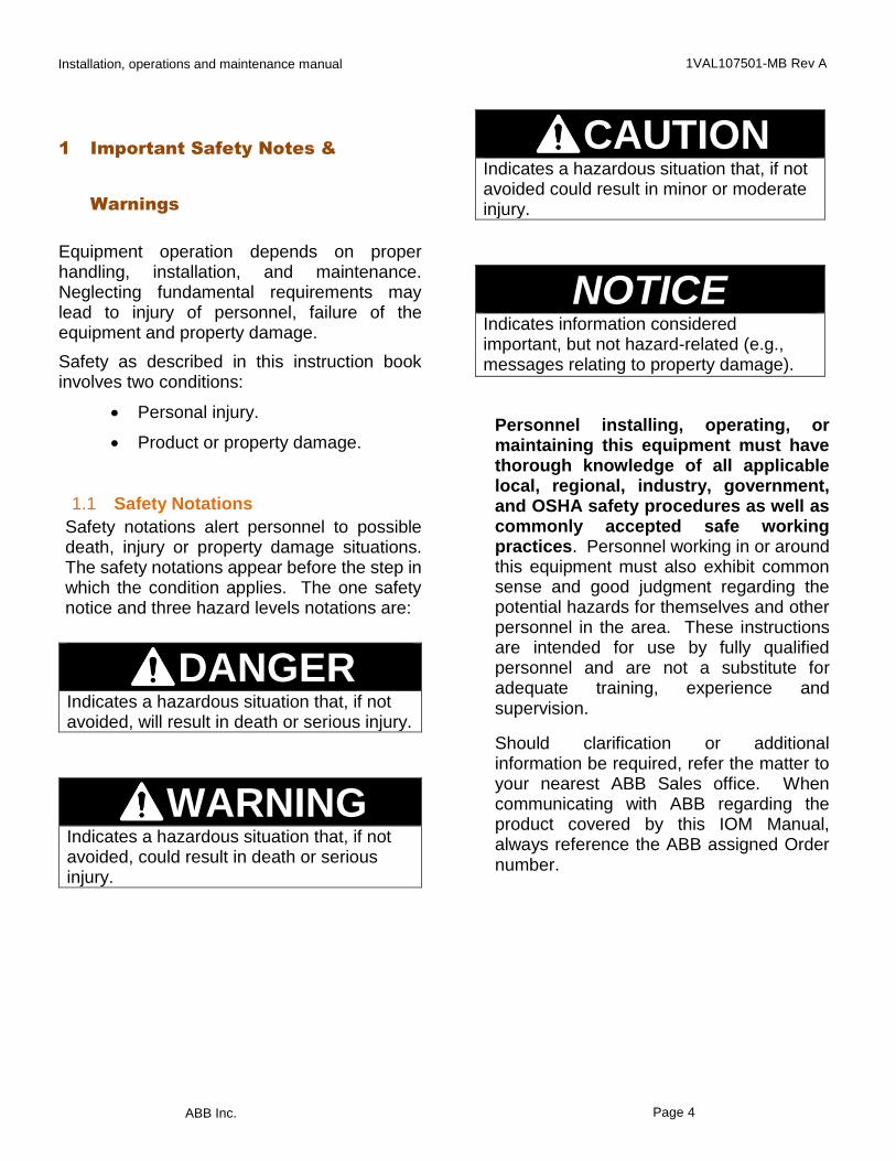
Safety notations alert personnel to possible death, injury or property damage situations. The safety notations appear before the step in which the condition applies. The one safety notice and three hazard levels notations are:
DANGER Indicates a hazardous situation that, if not avoided, will result in death or serious injury.
WARNING Indicates a hazardous situation that, if not avoided, could result in death or serious injury.
CAUTION Indicates a hazardous situation that, if not avoided could result in minor or moderate injury.
NOTICE Indicates information considered important, but not hazard-related (e.g., messages relating to property damage).
Personnel installing, operating, or maintaining this equipment must have thorough knowledge of all applicable local, regional, industry, government, and OSHA safety procedures as well as commonly accepted safe working practices. Personnel working in or around this equipment must also exhibit common sense and good judgment regarding the potential hazards for themselves and other personnel in the area. These instructions are intended for use by fully qualified personnel and are not a substitute for adequate training, experience and supervision.
Should clarification or additional information be required, refer the matter to your nearest ABB Sales office. When communicating with ABB regarding the product covered by this IOM Manual, always reference the ABB assigned Order number.
Installation, operations and maintenance manual 1VAL107501-MB Rev A
ABB Inc. Page 5
2 Introduction
2.1 General Instructions
Read these instructions carefully before installation and use as a guide during installation and initial operation.
File these instructions with other instruction books, drawings and descriptive data of the switchgear. Keep this book available for the installation, operation and maintenance of this equipment. Use of these instructions will facilitate proper maintenance of the equipment and prolong its useful life.
2.2 Scope of Instructions
The instructions are general in nature. They cover requirements for installation, setup, checkout and maintenance as applied to ABB ReliaGearTM ND medium-voltage, non-arc-resistant, switchgear. These instructions do not attempt to cover all variations and combinations of equipment and installations.
Information on particular installations appears in the following:
Bills of Materials that list electrical devices and equipment.
Single line drawings showing power connections.
Floor plan, representing available space for power & control conduits.
Special construction details.
Elementary and schematic diagrams.
Connection diagrams.
3 Receiving, Handling and Storage
3.1 Receiving Inspection
Before shipment, the equipment is inspected and marked with its number and position. Switchgear frames are factory-assembled and shipped with the doors closed. The factory ships circuit breakers in separate cartons, or as an option, inside the switchgear frame with the breakers in disconnect position.
Upon receipt of the equipment, examine the shipment for damage or missing components. Check the contents against the packing list before discarding any packing material. Check the consignment for completeness and lack of any damage (e.g., moisture and its detrimental effects). In case of doubt, the packing must be opened and then properly resealed, putting in new drying agent bags, when intermediate storage is necessary.
If any quantities are short, or defects or transport damage are noted, these must be documented on the respective shipping document. Notify ABB and the carrier at once of any discrepancies. If there is damage from improper handling, file a claim for damages at once with the carrier and notify ABB. Always photograph damage. Unless otherwise noted in the project contract documents, ABB standard shipments are “FOB Factory.” ABB is not responsible for damage after delivery of the equipment to the carrier.
3.2 Handling the Equipment
Transport panels upright. Take the high center of gravity into account. Carry out loading operations only when it has been ensured that all precautionary measures to protect personnel and materials have been taken into consideration.
Installation, operations and maintenance manual 1VAL107501-MB Rev A
ABB Inc. Page 6
NOTICEAll doors and panels must be in place and securely fastened before moving the equipment.
3.3 Storing the Equipment
Leave the equipment on the shipping base.
Store all equipment indoors in a well-ventilated area.
The storage building should have a well-drained paved floor. The temperature should be above 60°F. The air should be dry (60% maximum humidity).
The shipping sections are ship wrapped in plastic for protection during shipment only. Remove the plastic wrap after placing into storage. Cover with heavy wrapping paper or other moisture barrier. Use materials that will not trap moisture inside the unit. Do not cover louvered openings.
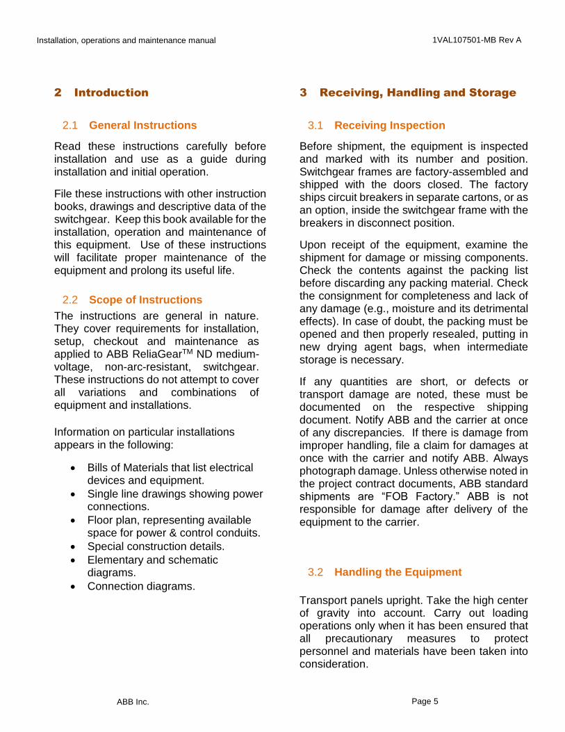
For long term storage, i.e., durations exceeding 2 weeks, or in high-humidity areas, use heaters to keep the interior dry. Bring power for the heaters to the load terminals of the device that controls the heater circuits (Figure 1).
NOTICERemove all the packing materials from the switchgear before energizing the heaters. Open the breaker or cutout device that controls the heaters when using a separate power source.
Figure 1: Heater load terminals in low voltage compartment
For circuit breakers shipped in crates, store circuit breakers upright in their original shipping carton oriented as indicated on the shipping crates. For circuit breakers shipped in the switchgear, do not remove for storage. See document 1VAL057601-MB Rev A for details on breaker storage.
4 Site Preparation
4.1 General
Before installing, consult all drawings furnished for the particular order. The drawings show top, front and section views of the lineup, primary and secondary connection diagrams, and Bills of Materials. Study these drawings and the following recommendations before preparing the site plan drawings. On commencement of installation on site, the switchgear room must be completely finished, provided with lighting and the electricity supply, be lockable, dry and have facilities for ventilation. All the necessary preparations, such as wall openings, ducts, etc., for positioning the power and control cables up to the switchgear must already be complete.

Installation, operations and maintenance manual 1VAL107501-MB Rev A
ABB Inc. Page 7
The ceiling height must also be checked
considering the top-mounted ventilation.
WARNING Drilling or punching of holes in the equipment in any way will affect the integrity of the switchgear. Consult the factory engineer before proceeding.
4.2 Location
Locate the lineup in accordance with local regulations. Clearances at the front should allow for installation and removal of the draw-out equipment. A minimum of 7’ 3” is recommended. Provide rear access for making connections before start-up and for periodic inspections and maintenance of 4’ minimum. Breaker doors can swing 115 degrees with adjacent doors closed.
4.3 Foundation
The ABB factory supplies General Arrangement and Floor Plan drawings for each installation. Refer to these drawings for floor leveling requirements. The finished floor under and in front of the switchgear line-up should be smooth, and shall not extend upwards above the switchgear floor line. Floor leveling requirements are +0.0” to -0.25” over a linear distance of 20’. For installations with concrete floors, install all power and secondary (control) conduits before moving the units to the site. Available space for the conduits appears on the floor plan drawings supplied with the switchgear. Conduits should not extend more than one inch above the station floor level. Plug conduit openings before pouring
concrete. For installations with steel floors, i.e., prefabricated metal buildings, cutouts for cable entry should not extend outside the space provided in the ReliaGear ND frames as shown on the floor plan drawings.
5 Indoor Installation
5.1 General
In order to obtain an optimum installation sequence and ensure adherence to high quality standards, site installation of the switchgear should only be carried out by specially trained and skilled personnel. Metal-clad switchgear ships in sections. These sections ship on disposable steel shipping bases. Equipment is not to be permanently installed on the shipping bases. Unload the units as close to the installation site as possible. Remove all drawout elements and secure all doors and panels. To move the shipping sections to their final position, one of 4 methods can be used.
NOTICEDo not remove the shipping bases until the units are set in place. Moving the units without the shipping base will cause irreparable damage and a hazardous condition.
Forklift – place forks through locations provided in the shipping bases (Figure 2, Figure 3).
Installation, operations and maintenance manual 1VAL107501-MB Rev A
ABB Inc. Page 8
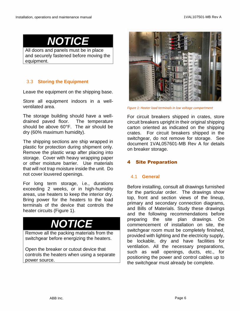
Figure 2: Forklift provisions in shipping channels
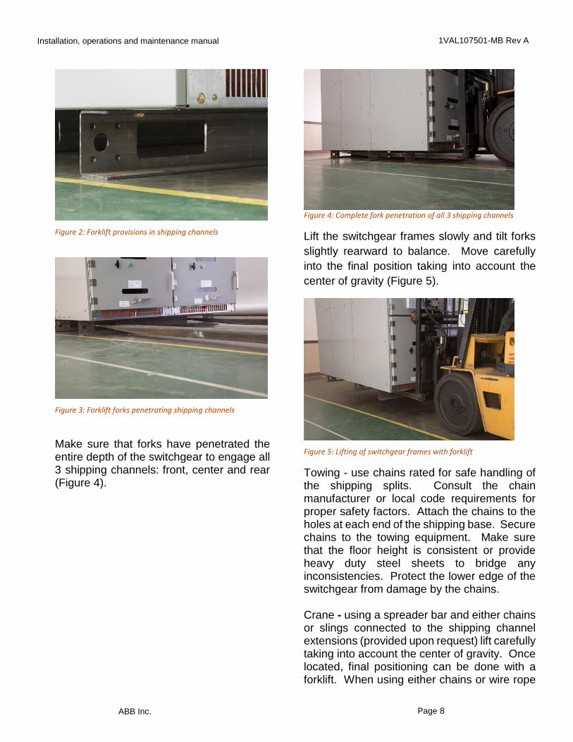
Figure 3: Forklift forks penetrating shipping channels
Make sure that forks have penetrated the entire depth of the switchgear to engage all 3 shipping channels: front, center and rear (Figure 4).
Figure 4: Complete fork penetration of all 3 shipping channels
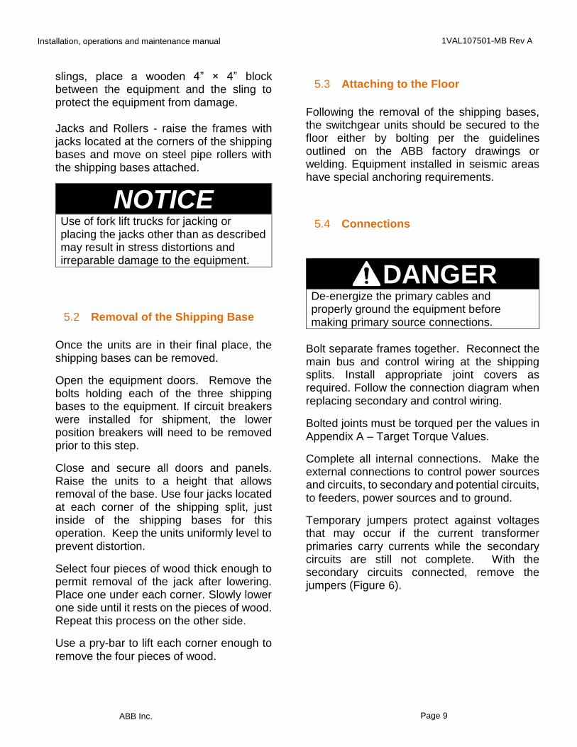
Lift the switchgear frames slowly and tilt forks
slightly rearward to balance. Move carefully
into the final position taking into account the
center of gravity (Figure 5).
Figure 5: Lifting of switchgear frames with forklift
Towing - use chains rated for safe handling of the shipping splits. Consult the chain manufacturer or local code requirements for proper safety factors. Attach the chains to the holes at each end of the shipping base. Secure chains to the towing equipment. Make sure that the floor height is consistent or provide heavy duty steel sheets to bridge any inconsistencies. Protect the lower edge of the switchgear from damage by the chains. Crane - using a spreader bar and either chains or slings connected to the shipping channel extensions (provided upon request) lift carefully taking into account the center of gravity. Once located, final positioning can be done with a forklift. When using either chains or wire rope
Installation, operations and maintenance manual 1VAL107501-MB Rev A
ABB Inc. Page 9
slings, place a wooden 4” × 4” block between the equipment and the sling to protect the equipment from damage. Jacks and Rollers - raise the frames with jacks located at the corners of the shipping bases and move on steel pipe rollers with the shipping bases attached.
NOTICEUse of fork lift trucks for jacking or placing the jacks other than as described may result in stress distortions and irreparable damage to the equipment.
5.2 Removal of the Shipping Base
Once the units are in their final place, the shipping bases can be removed.
Open the equipment doors. Remove the bolts holding each of the three shipping bases to the equipment. If circuit breakers were installed for shipment, the lower position breakers will need to be removed prior to this step.
Close and secure all doors and panels. Raise the units to a height that allows removal of the base. Use four jacks located at each corner of the shipping split, just inside of the shipping bases for this operation. Keep the units uniformly level to prevent distortion.
Select four pieces of wood thick enough to permit removal of the jack after lowering. Place one under each corner. Slowly lower one side until it rests on the pieces of wood. Repeat this process on the other side.
Use a pry-bar to lift each corner enough to remove the four pieces of wood.
5.3 Attaching to the Floor
Following the removal of the shipping bases, the switchgear units should be secured to the floor either by bolting per the guidelines outlined on the ABB factory drawings or welding. Equipment installed in seismic areas have special anchoring requirements.
5.4 Connections
DANGER De-energize the primary cables and properly ground the equipment before making primary source connections.
Bolt separate frames together. Reconnect the main bus and control wiring at the shipping splits. Install appropriate joint covers as required. Follow the connection diagram when replacing secondary and control wiring.
Bolted joints must be torqued per the values in Appendix A – Target Torque Values.
Complete all internal connections. Make the external connections to control power sources and circuits, to secondary and potential circuits, to feeders, power sources and to ground.
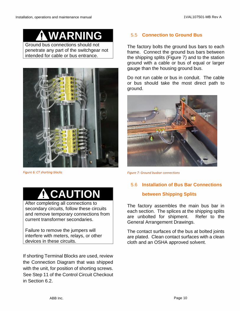
Temporary jumpers protect against voltages that may occur if the current transformer primaries carry currents while the secondary circuits are still not complete. With the secondary circuits connected, remove the jumpers (Figure 6).
Installation, operations and maintenance manual 1VAL107501-MB Rev A
ABB Inc. Page 10
WARNINGGround bus connections should not penetrate any part of the switchgear not intended for cable or bus entrance.
Figure 6: CT shorting blocks
CAUTION After completing all connections to secondary circuits, follow these circuits and remove temporary connections from current transformer secondaries. Failure to remove the jumpers will interfere with meters, relays, or other devices in these circuits.
If shorting Terminal Blocks are used, review
the Connection Diagram that was shipped
with the unit, for position of shorting screws.
See Step 11 of the Control Circuit Checkout
in Section 6.2.
5.5 Connection to Ground Bus
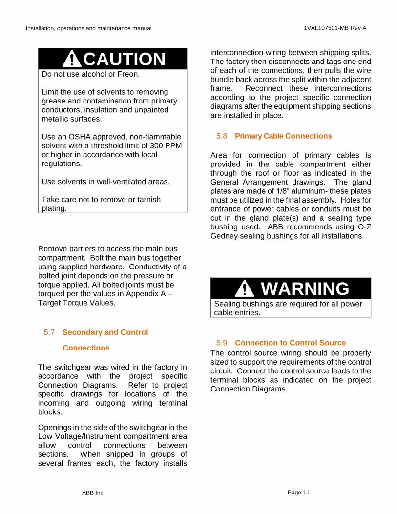
The factory bolts the ground bus bars to each frame. Connect the ground bus bars between the shipping splits (Figure 7) and to the station ground with a cable or bus of equal or larger gauge than the housing ground bus.
Do not run cable or bus in conduit. The cable or bus should take the most direct path to ground.
Figure 7: Ground busbar connections
5.6 Installation of Bus Bar Connections
between Shipping Splits
The factory assembles the main bus bar in each section. The splices at the shipping splits are unbolted for shipment. Refer to the General Arrangement Drawings.
The contact surfaces of the bus at bolted joints are plated. Clean contact surfaces with a clean cloth and an OSHA approved solvent.
Installation, operations and maintenance manual 1VAL107501-MB Rev A
ABB Inc. Page 11
CAUTION Do not use alcohol or Freon. Limit the use of solvents to removing grease and contamination from primary conductors, insulation and unpainted metallic surfaces. Use an OSHA approved, non-flammable solvent with a threshold limit of 300 PPM or higher in accordance with local regulations. Use solvents in well-ventilated areas. Take care not to remove or tarnish plating.
Remove barriers to access the main bus compartment. Bolt the main bus together using supplied hardware. Conductivity of a bolted joint depends on the pressure or torque applied. All bolted joints must be torqued per the values in Appendix A – Target Torque Values.
5.7 Secondary and Control
Connections
The switchgear was wired in the factory in accordance with the project specific Connection Diagrams. Refer to project specific drawings for locations of the incoming and outgoing wiring terminal blocks.
Openings in the side of the switchgear in the Low Voltage/Instrument compartment area allow control connections between sections. When shipped in groups of several frames each, the factory installs
interconnection wiring between shipping splits. The factory then disconnects and tags one end of each of the connections, then pulls the wire bundle back across the split within the adjacent frame. Reconnect these interconnections according to the project specific connection diagrams after the equipment shipping sections are installed in place.
5.8 Primary Cable Connections
Area for connection of primary cables is provided in the cable compartment either through the roof or floor as indicated in the General Arrangement drawings. The gland plates are made of 1/8” aluminum- these plates must be utilized in the final assembly. Holes for entrance of power cables or conduits must be cut in the gland plate(s) and a sealing type bushing used. ABB recommends using O-Z Gedney sealing bushings for all installations.
WARNING Sealing bushings are required for all power cable entries.
5.9 Connection to Control Source
The control source wiring should be properly sized to support the requirements of the control circuit. Connect the control source leads to the terminal blocks as indicated on the project Connection Diagrams.
Installation, operations and maintenance manual 1VAL107501-MB Rev A
ABB Inc. Page 12
WARNING Route secondary power and control wiring through the provided routes. Use rubber grommets cut with appropriate size center hole to accommodate the wiring bundle. Check electrical phasing before connecting.
5.10 Circuit Breaker: Lockout,
Insertion and Removal
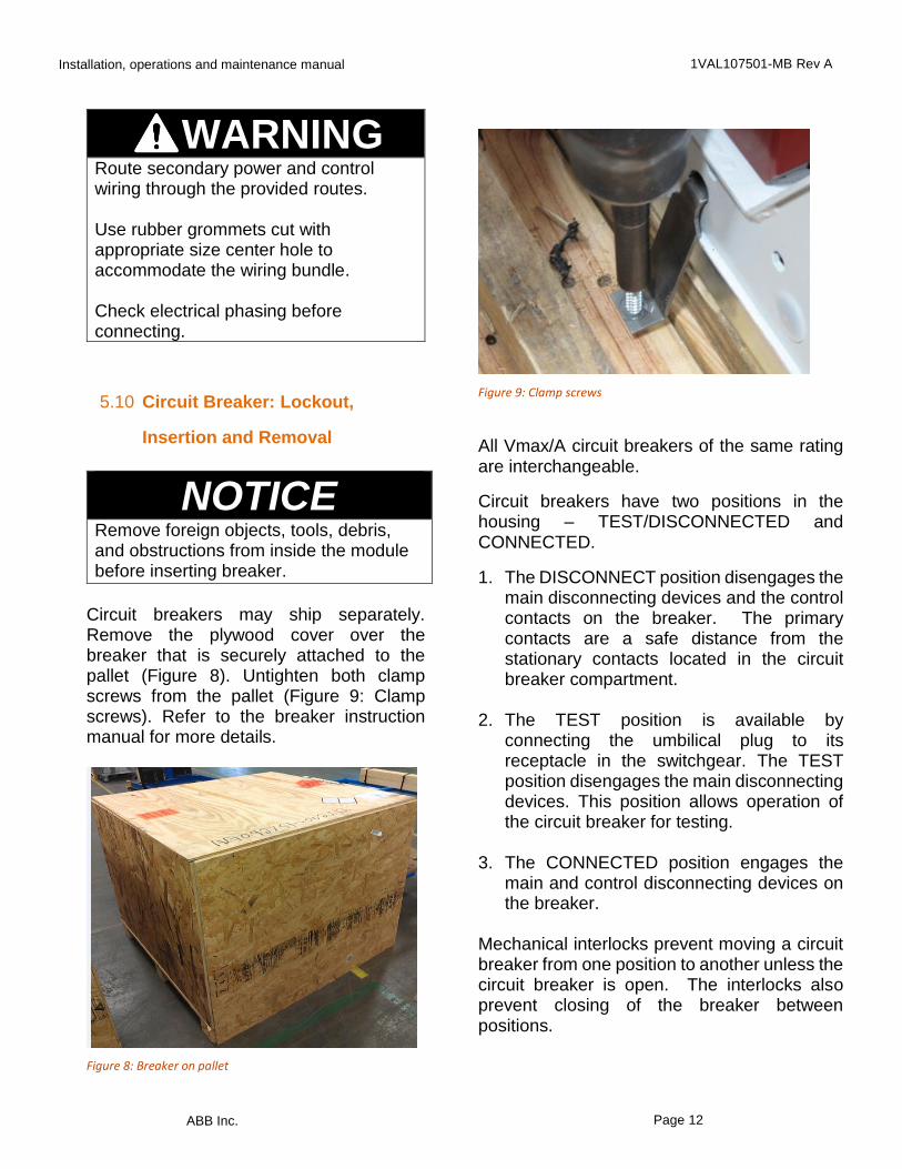
NOTICERemove foreign objects, tools, debris, and obstructions from inside the module before inserting breaker.
Circuit breakers may ship separately. Remove the plywood cover over the breaker that is securely attached to the pallet (Figure 8). Untighten both clamp screws from the pallet (Figure 9: Clamp screws). Refer to the breaker instruction manual for more details.
Figure 8: Breaker on pallet
Figure 9: Clamp screws
All Vmax/A circuit breakers of the same rating are interchangeable.
Circuit breakers have two positions in the housing – TEST/DISCONNECTED and CONNECTED.
1. The DISCONNECT position disengages the main disconnecting devices and the control contacts on the breaker. The primary contacts are a safe distance from the stationary contacts located in the circuit breaker compartment.
2. The TEST position is available by
connecting the umbilical plug to its receptacle in the switchgear. The TEST position disengages the main disconnecting devices. This position allows operation of the circuit breaker for testing.
3. The CONNECTED position engages the
main and control disconnecting devices on the breaker.
Mechanical interlocks prevent moving a circuit breaker from one position to another unless the circuit breaker is open. The interlocks also prevent closing of the breaker between positions.
Installation, operations and maintenance manual 1VAL107501-MB Rev A
ABB Inc. Page 13
Locking Out the Circuit Breaker
The circuit breaker may be locked out by padlocking both the racking port and door handle. It is recommended to use flat lockout hasps on both provisions (Figure 10).
Figure 10: Isometric view of circuit breaker door and available lockout provisions
Insertion
1. Open the breaker module door
completely (Figure 11).Door stops, if
available, can be used to keep the door
in position when operating the
equipment.
Figure 11: Breaker module with open door
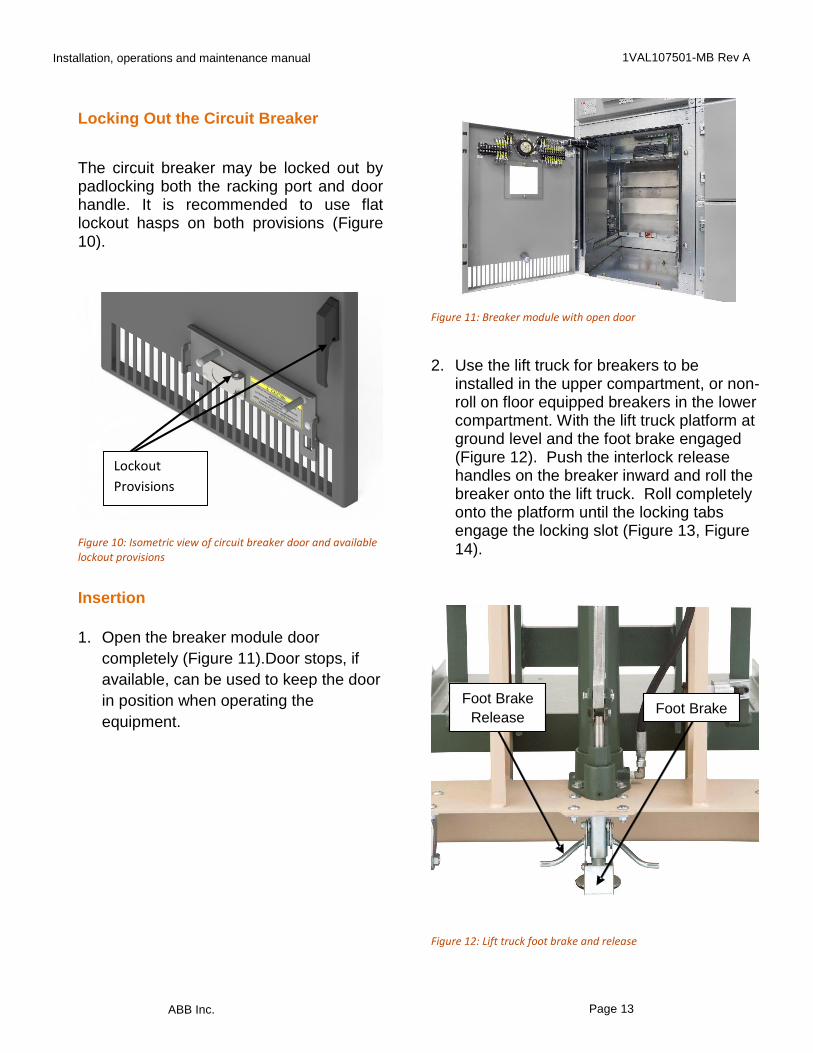
2. Use the lift truck for breakers to be
installed in the upper compartment, or non-roll on floor equipped breakers in the lower compartment. With the lift truck platform at ground level and the foot brake engaged (Figure 12). Push the interlock release handles on the breaker inward and roll the breaker onto the lift truck. Roll completely onto the platform until the locking tabs engage the locking slot (Figure 13, Figure 14).
Figure 12: Lift truck foot brake and release
Foot Brake
Release Foot Brake
Lockout
Provisions

Installation, operations and maintenance manual 1VAL107501-MB Rev A
ABB Inc. Page 14
Figure 13: Breaker locking tab and interlock release handle
Figure 14: Breaker lift truck pan side view
Engage breaker locking tabs with locking slot BEFORE raising the platform.
3. Raise the lift truck platform slightly
(approximately 1”) by cranking the winch or stepping on the foot pedal (Figure 15, Figure 16). Release the foot brake and push the lift truck towards the breaker cubicle (Figure 17).
Figure 15: Breaker lift truck winch
Figure 16: Lift truck foot pedal
Figure 17: Lift truck holding Vmax/A
4. Align the lift-truck with the front of the frame
Interlock
Release Handle
Breaker
Locking Tab
Locking Slots
Installation, operations and maintenance manual 1VAL107501-MB Rev A
ABB Inc. Page 15
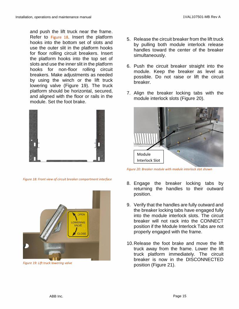
and push the lift truck near the frame. Refer to Figure 18. Insert the platform hooks into the bottom set of slots and use the outer slit in the platform hooks for floor rolling circuit breakers. Insert the platform hooks into the top set of slots and use the inner slit in the platform hooks for non-floor rolling circuit breakers. Make adjustments as needed by using the winch or the lift truck lowering valve (Figure 19). The truck platform should be horizontal, secured, and aligned with the floor or rails in the module. Set the foot brake.
Figure 18: Front view of circuit breaker compartment interface
Figure 19: Lift truck lowering valve
5. Release the circuit breaker from the lift truck by pulling both module interlock release handles toward the center of the breaker simultaneously.
6. Push the circuit breaker straight into the module. Keep the breaker as level as possible. Do not raise or lift the circuit breaker.
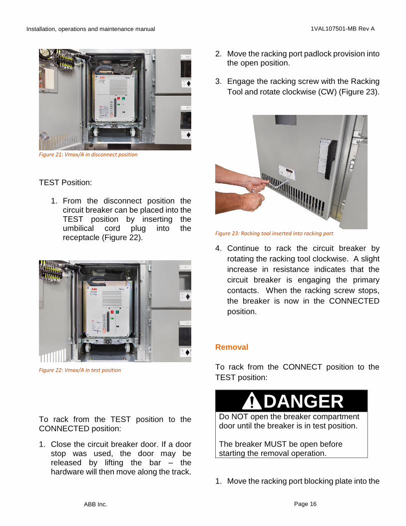
7. Align the breaker locking tabs with the
module interlock slots (Figure 20).
Figure 20: Breaker module with module interlock slot shown
8. Engage the breaker locking tabs by
returning the handles to their outward position.
9. Verify that the handles are fully outward and the breaker locking tabs have engaged fully into the module interlock slots. The circuit breaker will not rack into the CONNECT position if the Module Interlock Tabs are not properly engaged with the frame.
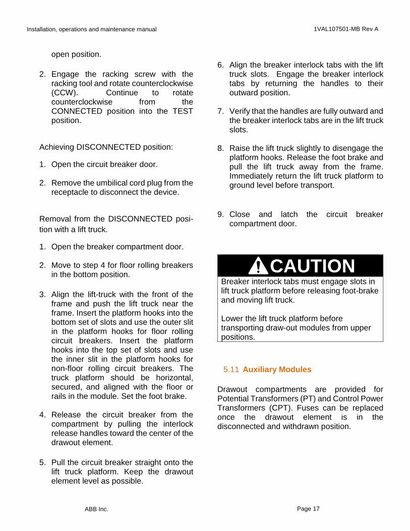
10. Release the foot brake and move the lift truck away from the frame. Lower the lift truck platform immediately. The circuit breaker is now in the DISCONNECTED position (Figure 21).
Module
Interlock Slot
Installation, operations and maintenance manual 1VAL107501-MB Rev A
ABB Inc. Page 16
Figure 21: Vmax/A in disconnect position
TEST Position:
1. From the disconnect position the circuit breaker can be placed into the TEST position by inserting the umbilical cord plug into the receptacle (Figure 22).
:
Figure 22: Vmax/A in test position
To rack from the TEST position to the CONNECTED position:
1. Close the circuit breaker door. If a door stop was used, the door may be released by lifting the bar – the hardware will then move along the track.
2. Move the racking port padlock provision into the open position.
3. Engage the racking screw with the Racking
Tool and rotate clockwise (CW) (Figure 23).
Figure 23: Racking tool inserted into racking port
4. Continue to rack the circuit breaker by
rotating the racking tool clockwise. A slight
increase in resistance indicates that the
circuit breaker is engaging the primary
contacts. When the racking screw stops,
the breaker is now in the CONNECTED
position.
Removal
To rack from the CONNECT position to the
TEST position:
DANGER Do NOT open the breaker compartment door until the breaker is in test position. The breaker MUST be open before starting the removal operation.
1. Move the racking port blocking plate into the
Installation, operations and maintenance manual 1VAL107501-MB Rev A
ABB Inc. Page 17
open position.
2. Engage the racking screw with the racking tool and rotate counterclockwise (CCW). Continue to rotate counterclockwise from the CONNECTED position into the TEST position.
Achieving DISCONNECTED position:
1. Open the circuit breaker door. 2. Remove the umbilical cord plug from the
receptacle to disconnect the device.
Removal from the DISCONNECTED posi-
tion with a lift truck.
1. Open the breaker compartment door. 2. Move to step 4 for floor rolling breakers
in the bottom position.
3. Align the lift-truck with the front of the frame and push the lift truck near the frame. Insert the platform hooks into the bottom set of slots and use the outer slit in the platform hooks for floor rolling circuit breakers. Insert the platform hooks into the top set of slots and use the inner slit in the platform hooks for non-floor rolling circuit breakers. The truck platform should be horizontal, secured, and aligned with the floor or rails in the module. Set the foot brake.
4. Release the circuit breaker from the
compartment by pulling the interlock release handles toward the center of the drawout element.
5. Pull the circuit breaker straight onto the lift truck platform. Keep the drawout element level as possible.
6. Align the breaker interlock tabs with the lift truck slots. Engage the breaker interlock tabs by returning the handles to their outward position.
7. Verify that the handles are fully outward and
the breaker interlock tabs are in the lift truck slots.
8. Raise the lift truck slightly to disengage the
platform hooks. Release the foot brake and pull the lift truck away from the frame. Immediately return the lift truck platform to ground level before transport.
9. Close and latch the circuit breaker compartment door.
CAUTIONBreaker interlock tabs must engage slots in lift truck platform before releasing foot-brake and moving lift truck. Lower the lift truck platform before transporting draw-out modules from upper positions.
5.11 Auxiliary Modules
Drawout compartments are provided for Potential Transformers (PT) and Control Power Transformers (CPT). Fuses can be replaced once the drawout element is in the disconnected and withdrawn position.
Installation, operations and maintenance manual 1VAL107501-MB Rev A
ABB Inc. Page 18
NOTICERemove foreign objects, tools, debris, and obstructions from inside the module before inserting breaker.
The procedure for Insertion, withdrawing
and removal of Auxiliary Drawout elements
is different from the procedure for the circuit
breaker. These elements do not have a
TEST position.
Insertion
To move the CPT or PT drawout element from the DISCONNECTED to the CONNECTED position:
1. If provided, remove the padlock from the CPT or PT module door and uncover the PT or CPT module push/pull port.
2. If the PT or CPT element is withdrawn,
use the handles to push the PT or CPT element back into the compartment to the disconnected position.
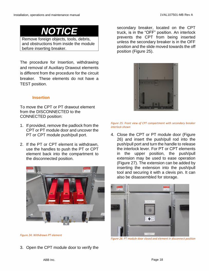
Figure 24: Withdrawn PT element
3. Open the CPT module door to verify the
secondary breaker, located on the CPT truck, is in the “OFF” position. An interlock prevents the CPT from being inserted unless the secondary breaker is in the OFF position and the slide moved towards the off position (Figure 25).
Figure 25: Front view of CPT compartment with secondary breaker interlock shown
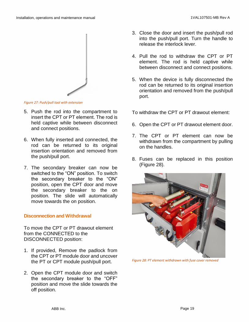
4. Close the CPT or PT module door (Figure 26) and insert the push/pull rod into the push/pull port and turn the handle to release the interlock lever. For PT or CPT elements in the upper position, the push/pull extension may be used to ease operation (Figure 27). The extension can be added by inserting the extension into the push/pull tool and securing it with a clevis pin. It can also be disassembled for storage.
Figure 26: PT module door closed and element in disconnect position
Installation, operations and maintenance manual 1VAL107501-MB Rev A
ABB Inc. Page 19
Figure 27: Push/pull tool with extension
5. Push the rod into the compartment to insert the CPT or PT element. The rod is held captive while between disconnect and connect positions.
6. When fully inserted and connected, the
rod can be returned to its original insertion orientation and removed from the push/pull port.
7. The secondary breaker can now be
switched to the “ON” position. To switch the secondary breaker to the “ON” position, open the CPT door and move the secondary breaker to the on position. The slide will automatically move towards the on position.
Disconnection and Withdrawal
To move the CPT or PT drawout element from the CONNECTED to the DISCONNECTED position:
1. If provided, Remove the padlock from
the CPT or PT module door and uncover the PT or CPT module push/pull port.
2. Open the CPT module door and switch
the secondary breaker to the “OFF” position and move the slide towards the off position.
3. Close the door and insert the push/pull rod into the push/pull port. Turn the handle to release the interlock lever.
4. Pull the rod to withdraw the CPT or PT element. The rod is held captive while between disconnect and connect positions.
5. When the device is fully disconnected the rod can be returned to its original insertion orientation and removed from the push/pull port.
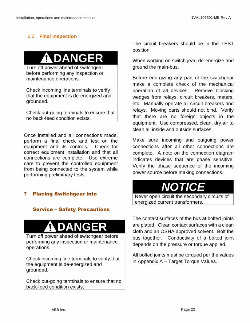
To withdraw the CPT or PT drawout element:
6. Open the CPT or PT drawout element door. 7. The CPT or PT element can now be
withdrawn from the compartment by pulling on the handles.
8. Fuses can be replaced in this position (Figure 28).
Figure 28: PT element withdrawn with fuse cover removed
Installation, operations and maintenance manual 1VAL107501-MB Rev A
ABB Inc. Page 20
6 Testing and Final Inspection
6.1 Testing
DANGER Disconnect the primary power source. Do NOT exceed the listed voltages for the voltage class of equipment under test. Disconnect shunt connected coils such as potential transformers. Do NOT test sensors or relays with high voltage. Disconnect all sensors and relays before applying voltage.
With the system erected, assembled and
connected, perform the following sixteen
step process.
1. Remove all packing and shipping materials.
2. Make sure that all internal parts are
clean and dry. If moisture is present, blow dry with warm air.
3. Remove any shipping blocks from
relays. 4. Check for damaged insulation by
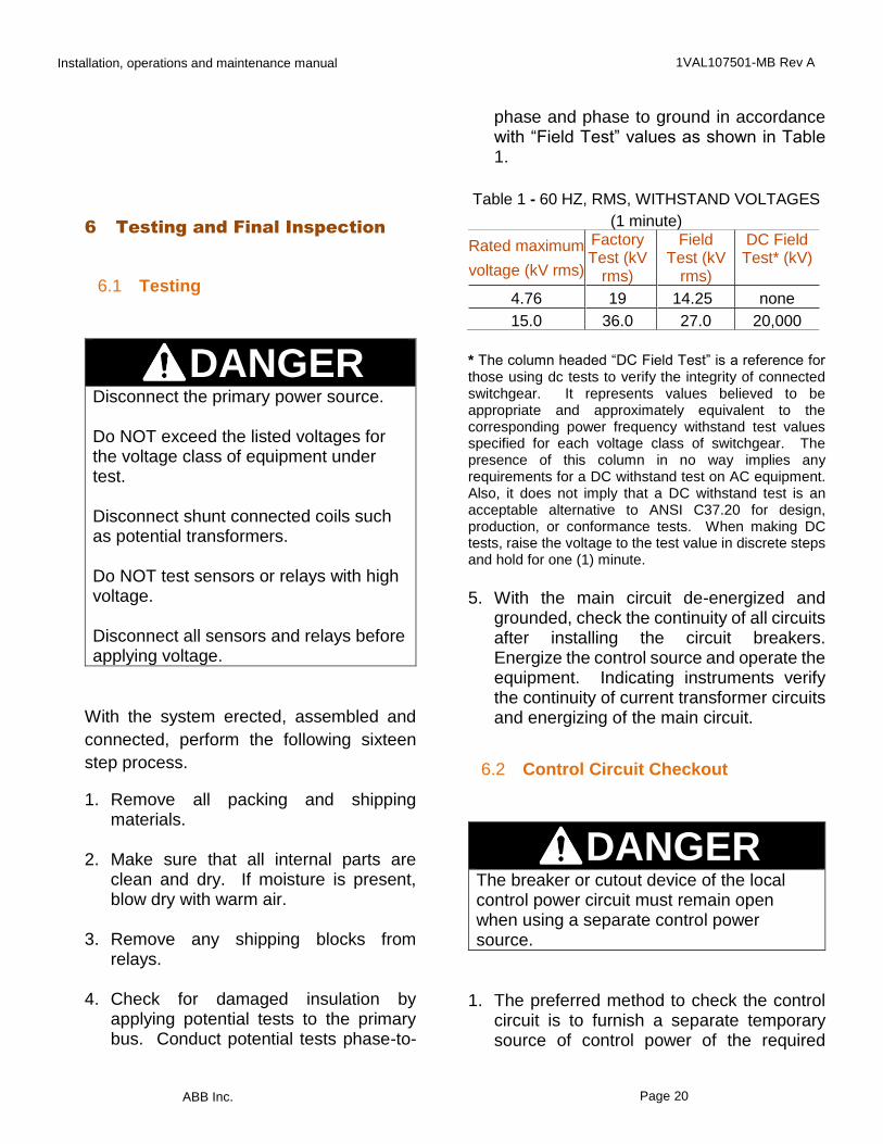
applying potential tests to the primary bus. Conduct potential tests phase-to-
phase and phase to ground in accordance with “Field Test” values as shown in Table 1.
Table 1 - 60 HZ, RMS, WITHSTAND VOLTAGES
(1 minute)
Rated maximum
voltage (kV rms)
Factory Test (kV
rms)
Field Test (kV
rms)
DC Field Test* (kV)
4.76 19 14.25 none
15.0 36.0 27.0 20,000
* The column headed “DC Field Test” is a reference for those using dc tests to verify the integrity of connected switchgear. It represents values believed to be appropriate and approximately equivalent to the corresponding power frequency withstand test values specified for each voltage class of switchgear. The presence of this column in no way implies any requirements for a DC withstand test on AC equipment. Also, it does not imply that a DC withstand test is an acceptable alternative to ANSI C37.20 for design, production, or conformance tests. When making DC tests, raise the voltage to the test value in discrete steps and hold for one (1) minute.
5. With the main circuit de-energized and
grounded, check the continuity of all circuits after installing the circuit breakers. Energize the control source and operate the equipment. Indicating instruments verify the continuity of current transformer circuits and energizing of the main circuit.
6.2 Control Circuit Checkout
DANGER The breaker or cutout device of the local control power circuit must remain open when using a separate control power source.
1. The preferred method to check the control
circuit is to furnish a separate temporary source of control power of the required
Installation, operations and maintenance manual 1VAL107501-MB Rev A
ABB Inc. Page 21
control voltage rating. The temporary source must have a properly coordinated backup protective device in the circuit. Set the device to clear any faults that might occur. Initially all circuit breakers should be in the DISCONNECT position and the main circuit de-energized and grounded. When AC control power is supplied from control power transformers in the switchgear, remove all fuses in the transformer circuits.
2. Rack and place all circuit breakers to the
DISCONNECT position. 3. Open all normal control power source
disconnects, if supplied. 4. Check each control switch or push-
button. Make sure that it is in the OPEN position.
5. Connect a temporary control power
source to the circuit load terminals in the switchgear. Energize the control circuit from the temporary control power source. Refer to the project specific electrical drawings for connections.
6. Place one circuit breaker into the TEST
position. When the on-off switch is in the ON position, the charging of the closing springs of an electrically operated circuit breaker indicates connection to the control power.
7. Rack the remaining circuit breakers into
the TEST position, one at a time and verify that each is connected to control power.
8. Test all electrically and manually operated breakers for closing and tripping, while they are in the TEST position.
9. De-energize the control circuit. If AC control power is from transformers in the switchgear, remove the temporary separate source of control power. Reinstall all fuses in the transformer circuit.
10. Set all relays, regulators, and other devices for proper operation of loads. The factory does not set the relays.
11. Remove shorting screws from the terminal blocks in the current transformer circuits. Store screws in the tapped holes in the corners of the blocks.
Note: Verify the proper phasing of all main circuits
according to connection diagram.
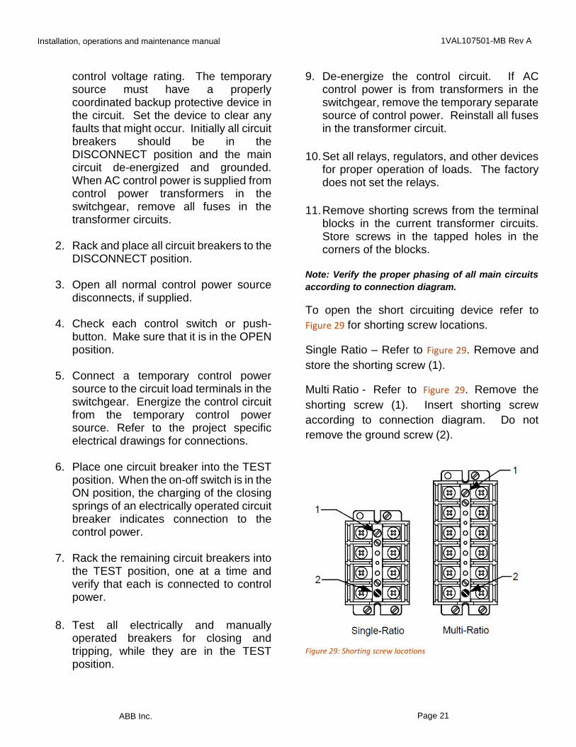
To open the short circuiting device refer to
Figure 29 for shorting screw locations.
Single Ratio – Refer to Figure 29. Remove and
store the shorting screw (1).
Multi Ratio - Refer to Figure 29. Remove the
shorting screw (1). Insert shorting screw
according to connection diagram. Do not
remove the ground screw (2).
Figure 29: Shorting screw locations
Installation, operations and maintenance manual 1VAL107501-MB Rev A
ABB Inc. Page 22
6.3 Final Inspection
DANGER Turn off power ahead of switchgear before performing any inspection or maintenance operations. Check incoming line terminals to verify that the equipment is de-energized and grounded. Check out-going terminals to ensure that no back-feed condition exists.
Once installed and all connections made, perform a final check and test on the equipment and its controls. Check for correct equipment installation and that all connections are complete. Use extreme care to prevent the controlled equipment from being connected to the system while performing preliminary tests.
7 Placing Switchgear into
Service – Safety Precautions
DANGER Turn off power ahead of switchgear before performing any inspection or maintenance operations. Check incoming line terminals to verify that the equipment is de-energized and grounded. Check out-going terminals to ensure that no back-feed condition exists.
The circuit breakers should be in the TEST
position.
When working on switchgear, de-energize and
ground the main-bus.
Before energizing any part of the switchgear
make a complete check of the mechanical
operation of all devices. Remove blocking
wedges from relays, circuit breakers, meters,
etc. Manually operate all circuit breakers and
relays. Moving parts should not bind. Verify
that there are no foreign objects in the
equipment. Use compressed, clean, dry air to
clean all inside and outside surfaces.
Make sure incoming and outgoing power
connections after all other connections are
complete. A note on the connection diagram
indicates devices that are phase sensitive.
Verify the phase sequence of the incoming
power source before making connections.
NOTICENever open circuit the secondary circuits of energized current transformers.
The contact surfaces of the bus at bolted joints
are plated. Clean contact surfaces with a clean
cloth and an OSHA approved solvent. Bolt the
bus together. Conductivity of a bolted joint
depends on the pressure or torque applied.
All bolted joints must be torqued per the values
in Appendix A – Target Torque Values.
Installation, operations and maintenance manual 1VAL107501-MB Rev A
ABB Inc. Page 23
7.1 Energizing the Main Bus
Verify that all door and panel hardware is
secure.
After completing the control circuit
checkout, energize the control equipment
main bus.
Verify the settings and integrity of all relays,
regulators, and other devices for proper
operation of loads
Energize the incoming bus to the main
circuit breaker of the equipment. Confirm
correct operation of all relays, regulators,
and other devices for proper operation of
loads.
Energize the separate control power
source, if furnished.
Energize the switchgear main bus by
closing the main circuit breaker. Observe if
operation of all relays, regulators, and other
devices for proper operation of loads are
correct.
Rack the circuit breakers to the
CONNECTED position.
Close the desired feeder and tie-breaker
circuit breakers.
8 Standard Construction
8.1 Standard Color
The standard paint color is ANSI 61. This
finish is electro-static powder paint applied
over an iron phosphate coating. This
process achieves a smooth, uniform paint
finish that conforms to applicable UL
requirements.
8.2 Galvanized Steel Frame
Construction
Unpainted parts are made of galvanized steel.
Galvanized steel greatly exceeds the paint
qualifications of ANSI C37.20.2 Section 5.2.8.
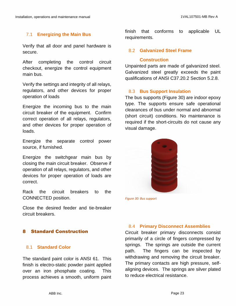
8.3 Bus Support Insulation
The bus supports (Figure 30) are indoor epoxy
type. The supports ensure safe operational
clearances of bus under normal and abnormal
(short circuit) conditions. No maintenance is
required if the short-circuits do not cause any
visual damage.
Figure 30: Bus support
8.4 Primary Disconnect Assemblies
Circuit breaker primary disconnects consist
primarily of a circle of fingers compressed by
springs. The springs are outside the current
path. The fingers can be inspected by
withdrawing and removing the circuit breaker.
The primary contacts are high pressure, self-
aligning devices. The springs are silver plated
to reduce electrical resistance.
Installation, operations and maintenance manual 1VAL107501-MB Rev A
ABB Inc. Page 24
8.5 Secondary Disconnecting
Devices
Circuit breakers have umbilical cords sized for the required current. They are connected in the DISCONNECT position and remain connected into the CONNECT position.
8.6 Ground Bus
The ground bus is located in the bus and
cable compartment. The circuit breakers
are grounded through the wheels in all
positions.
8.7 Control Wires
ABB standard control wiring is insulated
type SIS, made of flexible stranded
conductors, unless otherwise specified by
contract specifications.
9 Maintenance
9.1 General
Inspect all switchgear installations at
frequent intervals. Perform a visual
inspection, front and rear, to see that there
is no evidence of loose parts, warping, or
undue vibration. Check instrumentation for
undue noise. Take steps to remedy any
deficiencies of this nature that may appear.
Keep the assembly dry. Cover to prevent
moisture from dripping on equipment. Do not
block vents or flaps.
DANGER Turn off power ahead of switchgear before performing any inspection or maintenance operations. Check incoming line terminals to verify that the equipment is de-energized and grounded. Check out-going terminals to ensure that no back-feed condition exists.
Installation, operations and maintenance manual 1VAL107501-MB Rev A
ABB Inc. Page 25
9.2 Annual Inspection
Perform the following recommended inspection and maintenance once a year, or sooner, if required by local conditions or regulations.
1. Perform an overall visual inspection. 2. Check all indicators, meters and
instruments for proper operation.
3. Make sure all bolted connections are secure. All bolted joints must be torqued per the values in Appendix A – Target Torque Values. Bolted connections should be tight. Discoloration, excessive corrosion, embrittlement or discolored insulation may indicate an overheated connection. If found, follow the procedure described under section 9.5 “Bolted Joint Maintenance.”
4. Verify operation of heaters and thermostats, if used.
5. Check for undue noise and vibration that might loosen bolted connections.
6. Look for evidence of moisture in the switchgear. Evidence of moisture can be but not limited to water droplets, condensation, oxidized metal, etc.
7. Inspect all cables for tight connections and ample support.
8. Inspect control wiring for signs of wear and damage, especially at door hinge locations. Replace wire wherever doubtful.
9. Examine resistors and other devices prone to overheating.
10. Open all hinged doors and inspect
hinges and latches.
11. Clean insulation thoroughly.
CAUTION Do not use alcohol or Freon. Limit the use of solvents to removing grease and contamination from primary conductors, insulation and unpainted metallic surfaces. Use an OSHA approved, non-flammable solvent with a threshold limit of 300 PPM or higher in accordance with local regulations. Use solvents in well-ventilated areas.
12. Withdraw and clean all drawout
components. Refer to Circuit Breaker Installation Operation and Maintenance Manual 1VAL057601-MB Rev A before cleaning contacts.
13. Clean the stationary portion of the switchgear by wiping with a clean cloth. Use dry, compressed air in inaccessible areas.
14. Remove the covers of all panel devices
where possible. Check wiring for secure connections. Clean contacts on relays and switches wherever necessary. Replace covers.
15. Remove air filters when used. Flush with
clean water if necessary. Coat filters with Randolf Products’, Super Coat Adhesive or equivalent.
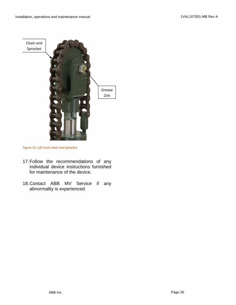
16. Inspect the chains/sprocket (Figure 31) and
the lifting rail of lift truck, if used for normal operation. For normal operation use a heavy gear lubricant. In very dirty or gritty conditions, use a dry lubricant.
Installation, operations and maintenance manual 1VAL107501-MB Rev A
ABB Inc. Page 26
Figure 31: Lift truck chain and sprocket
17. Follow the recommendations of any
individual device instructions furnished for maintenance of the device.
18. Contact ABB MV Service if any abnormality is experienced.
Chain and
Sprocket
Grease
Zirk
Installation, operations and maintenance manual 1VAL107501-MB Rev A
ABB Inc. Page 27
9.3 24 Month (Two Year) Inspection
In addition to the annual inspection, perform the following recommended inspection and maintenance at 24 month (two year) intervals, or sooner, if required by local conditions or regulations.
DANGER Turn off power ahead of switchgear before performing any inspection or maintenance operations. Check incoming line terminals to verify that the equipment is de-energized and grounded. Check out-going terminals to ensure that no back-feed condition exists.
1. Clean the circuit breaker stationary
primary contacts. Refer to Circuit Breaker Installation Operation and Maintenance Manual 1VAL057601-MB Rev A for detailed instructions.
2. Inspect secondary wiring bundles for
signs of discoloration because of heat or chafing. Check for cracked or embrittled insulation. Replace wire whenever unsure.
3. Inspect primary insulation system for accumulated contamination. Clean insulation with a dry cloth, dry-air, vacuum, or if necessary with an OSHA approved solvent.
4. Check the calibration of protective relays.
5. Follow the recommendations of any individual device instructions furnished
for maintenance of the device.
6. Contact ABB MV Service if any abnormality is experienced.
Installation, operations and maintenance manual 1VAL107501-MB Rev A
ABB Inc. Page 28
9.4 10 Year Maximum Inspection
In addition to the annual inspections and maintenance, perform the following recommended inspections and maintenance every ten years, or sooner, if required by local conditions or regulations.
DANGER Turn off power ahead of switchgear before performing any inspection or maintenance operations. Check incoming line terminals to verify that the equipment is de-energized and grounded. Check out-going terminals to ensure that no back-feed condition exists.
1. Disassemble, inspect, clean, lubricate, adjust and calibrate circuit breaker mechanisms as recommended in the instructions furnished with the circuit breaker.
2. Torque all primary conductor connection bolts to recommended values. All bolted joints must be torqued per the values in Appendix A – Target Torque Values.
3. Tighten all secondary control wire connections. Check for loose lug crimps and broken wire strands.
4. Contact ABB MV Service if any abnormality is experienced.
Installation, operations and maintenance manual 1VAL107501-MB Rev A
ABB Inc. Page 29
9.5 Bolted Joint Maintenance
DANGER Turn off power ahead of switchgear before performing any inspection or maintenance operations. Check incoming line terminals to verify that the equipment is de-energized and grounded. Check out-going terminals to ensure that no back-feed condition exists.
1. Tighten all secondary control wire connections. Check for loose lug crimps and broken wire strands.
2. Open bus joints and inspect connection
surfaces. 3. Clean surfaces with an OSHA approved
solvent. Dress contact surfaces that show minor corrosion or pitting by lightly rubbing with a polishing cloth such as “3M Scotch Brite”. Take care to minimize the removal of plating.
4. Replace parts that show signs of heavy
corrosion, arcing or melting. 5. Replace contact fingers and springs
after exposure to excess heating at the breaker disconnect.
6. Before assembly, protect contact
surfaces with No-Ox-ID ‘Special A Compound’, a product of Sanchem Chemical Co., ABB Part No. 713222A00, or equivalent.
7. Use proper torque in tightening bolted
connections. All bolted joints must be torqued per the values in Appendix A – Target Torque Values.
9.6 Care of Finish
The paint and galvanized finish is strong and
durable. Always keep the switchgear clean.
Wiping with a clean dry cloth will usually suffice.
To remove oil and grease marks, use warm
water and soap, and wipe dry with a clean, dry,
soft cloth.
Because the color and finish may vary, consult
the front sheet of the Bill of Materials before
using touch-up paint. The standard paint color
is ANSI 61, light gray.
9.7 Renewal Parts
Previous experience and the number of vertical
sections in service are the best guidelines for
determining the stocking of replacement parts.
Order factory original replacement parts from
ABB Inc., Lake Mary, Florida 32746. Specify
quantity, part numbers, description, and
nameplate data of the device requiring the
replacement parts.
For replacement parts, call toll free: 1-800-
929-SWGR.
Outside of USA call: 1-407-732-2000

Installation, operations and maintenance manual 1VAL107501-MB Rev A
ABB Inc. Page 30
9.9 Appendix A – Target Torque Values
Table 2 – Target Torque Values
Hardware Size
Hardware Style Min. Torque ft-lbs.
Max Torque ft-lbs.
Target Torque (ft-lbs.)
4-40 Slotted Head .42 .5 .42
6-32 Slotted Head .75 .92 .83
8-32 Slotted Head 1.3 1.5 1.42
10-32 Phillips Head 3.12 3.33 3.25
10-32 Self-Tapping 5.83 6.67 6.25
1/4-20 Self-Tapping .104” Matl. Thickness 8 11 10
1/4-20 Self-Tapping .119” Matl. Thickness 13 16 15
1/4-20 Carriage Bolt 10 11 11
1/4-20 Hex Head 10 11 11
5/16-18 Hex Head 17 20 19
3/8-16 Carriage Bolt 35 38 37
3/8-16 Hex Head 17 20 19
3/8-16 Flange Bolt 35 38 37
3/8-16 Flange Bolt (For Stand-off Insulators) 33 35 34
3/8-16 Threaded Stud 18 20 19
3/8-16 Fiberglass Threaded Stud 10 12 11
1/2-13 Hex Head 55 62 59
5/8-11 Hex Head 35 40 38
Installation, operations and maintenance manual 1VAL107501-MB Rev A
ABB Inc. Page 31
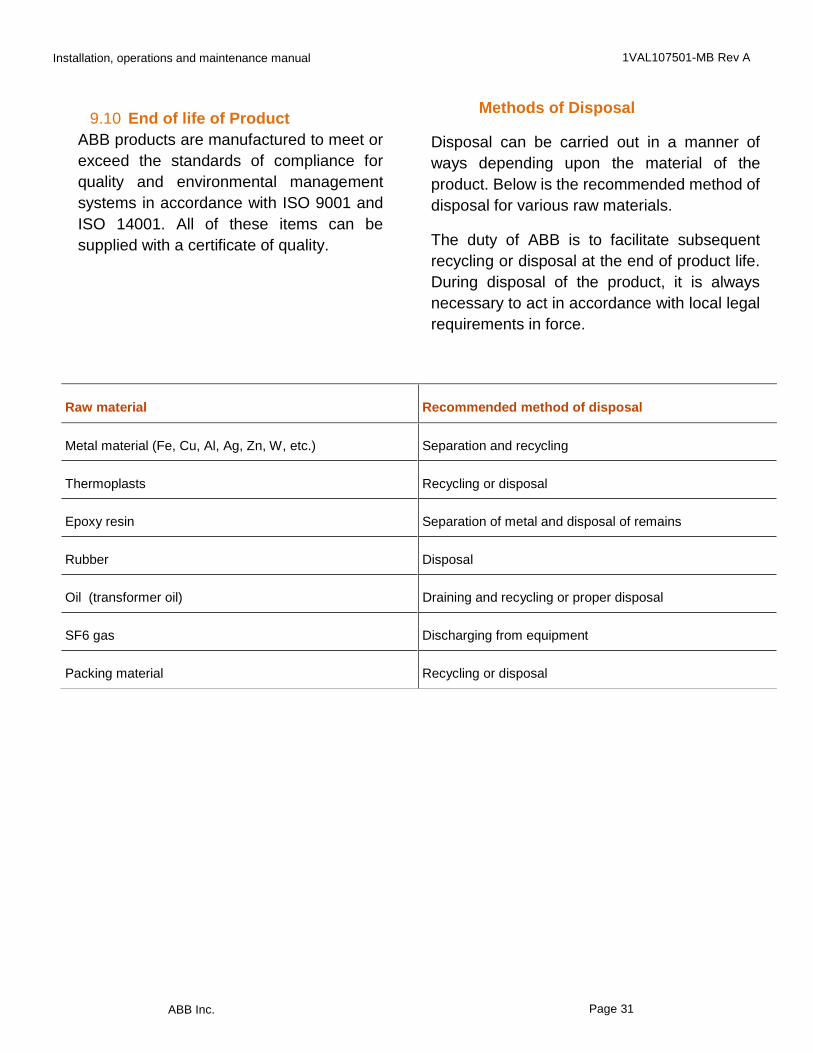
9.10 End of life of Product
ABB products are manufactured to meet or
exceed the standards of compliance for
quality and environmental management
systems in accordance with ISO 9001 and
ISO 14001. All of these items can be
supplied with a certificate of quality.
Methods of Disposal
Disposal can be carried out in a manner of
ways depending upon the material of the
product. Below is the recommended method of
disposal for various raw materials.
The duty of ABB is to facilitate subsequent
recycling or disposal at the end of product life.
During disposal of the product, it is always
necessary to act in accordance with local legal
requirements in force.
Raw material
Recommended method of disposal
Metal material (Fe, Cu, Al, Ag, Zn, W, etc.)
Separation and recycling
Thermoplasts
Recycling or disposal
Epoxy resin
Separation of metal and disposal of remains
Rubber
Disposal
Oil (transformer oil)
Draining and recycling or proper disposal
SF6 gas
Discharging from equipment
Packing material
Recycling or disposal

Installation, operations and maintenance manual 1VAL107501-MB Rev A
ABB Inc. Page 32
9.11 Disclaimer of Warranties and Limitation of Liability
DISCLAIMER OF WARRANTIES AND LIMITATION OF LIABILITY
There are no understandings, agreements, representations of warranties, expressed or implied,
including warranties of merchantability or fitness for a particular purpose, other than those specifically
set out by an existing contract between the parties. Any such contract states the entire obligation of
the seller. The contents of this document shall not become part of or modify any prior or existing
agreement, commitment or relationship. The information, recommendations, descriptions and safety
notations in this document are based on ABB experience and judgment with respect to metal-clad and
metal-enclosed switchgear. This information should not be considered to be all inclusive or covering
all contingencies.
No warranties, expressed or implied, including warranties of fitness for a particular purpose or
merchantability, or warranties of fitness for a particular purpose or merchantability, or warranties
arising from course of dealing or usage of trade, are made regarding the information,
recommendations, descriptions and safety notations contained herein. In no event will ABB be
responsible to the user in contract, in tort (including negligence), strict liability or otherwise for any
special, indirect, incidental or consequential damage or loss whatsoever including but not limited to
damage to or loss of use of equipment, plant or power system, cost of capital, loss of profits or revenue,
cost of replacement power, additional expenses in the use of existing power facilities, or claims against
the user by its customers resulting from the use of information, recommendations, descriptions and
safety notations contained herein.
Page 20
ABB Inc. Medium Voltage Apparatus 655 Century Point Lake Mary, Florida 32746 Phone: +1 407 732 2000 Customer service: +1 800 929 7947 ext. 5
+1 407 732 2000 ext. 5 E-Mail: [email protected]
ABB Inc. Medium Voltage Service 2300 Mechanicsville Road Florence, South Carolina 29501 Phone: +1 800 HELP 365 (option 7)
+1 407 732 2000
www.abb.com/mediumvoltage www.abb.us/mvservice
The information contained in this document is for general information
purposes only. While ABB strives to keep the information up to date and
correct, it makes no representations or warranties of any kind, express or
implied, about the completeness, accuracy, reliability, suitability or
availability with respect to the information, products, services, or related
graphics contained in the document for any purpose. Any reliance placed
on such information is therefore strictly at your own risk. ABB reserves the
right to discontinue any product or service at any time.
© Copyright 2015 ABB. All rights reserved.
1V
AL
10
75
01
-MB
Rev A
Ap
ril 2
01
5