reliance-ss curtain wall - obe · 2019-11-25 · reliance-ss curtain wall installation and glazing...
TRANSCRIPT
RELIANCE-SS CURTAIN WALL
INSTALLATION AND GLAZING MANUAL
®
Note:
The installation details found in this package are generic and are for
representation only with the intent of giving the installation team a visual
representation as to how the assemblies typically install. The shop drawings and
details are the governing documents and as such this package is to be used only
as a resource.
Follow sealant manufacturers recommendations for use and application of
structural silicone sealant and weather seal silicone sealant.
Note: Customer / Project quality assurance procedures are separate dociments
and are to be followed in conjunction with this manual.
November 20191-866-OLDCASTLE (653-2278)
Web: www.obe.com1
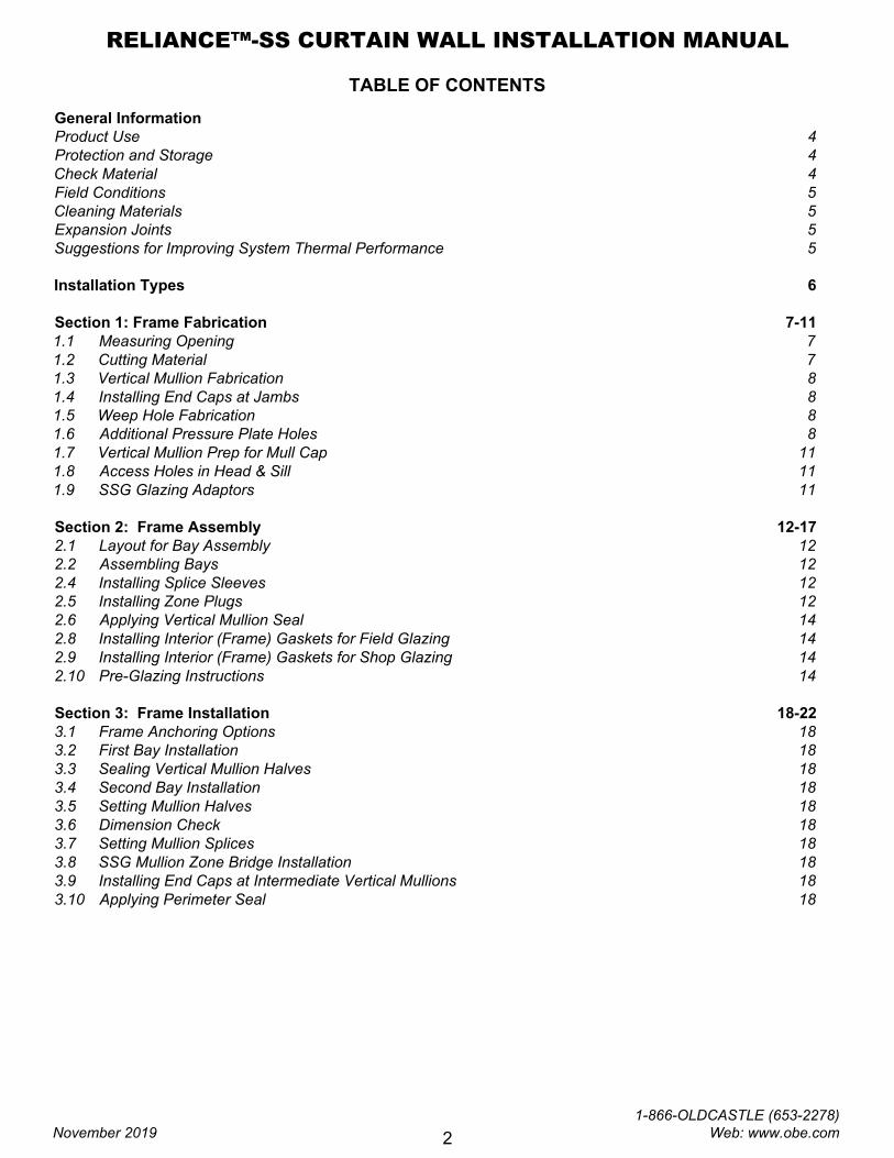
TABLE OF CONTENTS
General Information
Product Use 4
Protection and Storage 4
Check Material 4
Field Conditions 5
Cleaning Materials 5
Expansion Joints 5
Suggestions for Improving System Thermal Performance 5
Installation Types 6
Section 1: Frame Fabrication 7-11
1.1 Measuring Opening 7
1.2 Cutting Material 7
1.3 Vertical Mullion Fabrication 8
1.4 Installing End Caps at Jambs 8
1.5 Weep Hole Fabrication 8
1.6 Additional Pressure Plate Holes 8
1.7 Vertical Mullion Prep for Mull Cap 11
1.8 Access Holes in Head & Sill 11
1.9 SSG Glazing Adaptors 11
Section 2: Frame Assembly 12-17
2.1 Layout for Bay Assembly 12
2.2 Assembling Bays 12
2.4 Installing Splice Sleeves 12
2.5 Installing Zone Plugs 12
2.6 Applying Vertical Mullion Seal 14
2.8 Installing Interior (Frame) Gaskets for Field Glazing 14
2.9 Installing Interior (Frame) Gaskets for Shop Glazing 14
2.10 Pre-Glazing Instructions 14
Section 3: Frame Installation 18-22
3.1 Frame Anchoring Options 18
3.2 First Bay Installation 18
3.3 Sealing Vertical Mullion Halves 18
3.4 Second Bay Installation 18
3.5 Setting Mullion Halves 18
3.6 Dimension Check 18
3.7 Setting Mullion Splices 18
3.8 SSG Mullion Zone Bridge Installation 18
3.9 Installing End Caps at Intermediate Vertical Mullions 18
3.10 Applying Perimeter Seal 18
RELIANCE™-SS CURTAIN WALL INSTALLATION MANUAL
November 2019
1-866-OLDCASTLE (653-2278) Web: www.obe.com
2
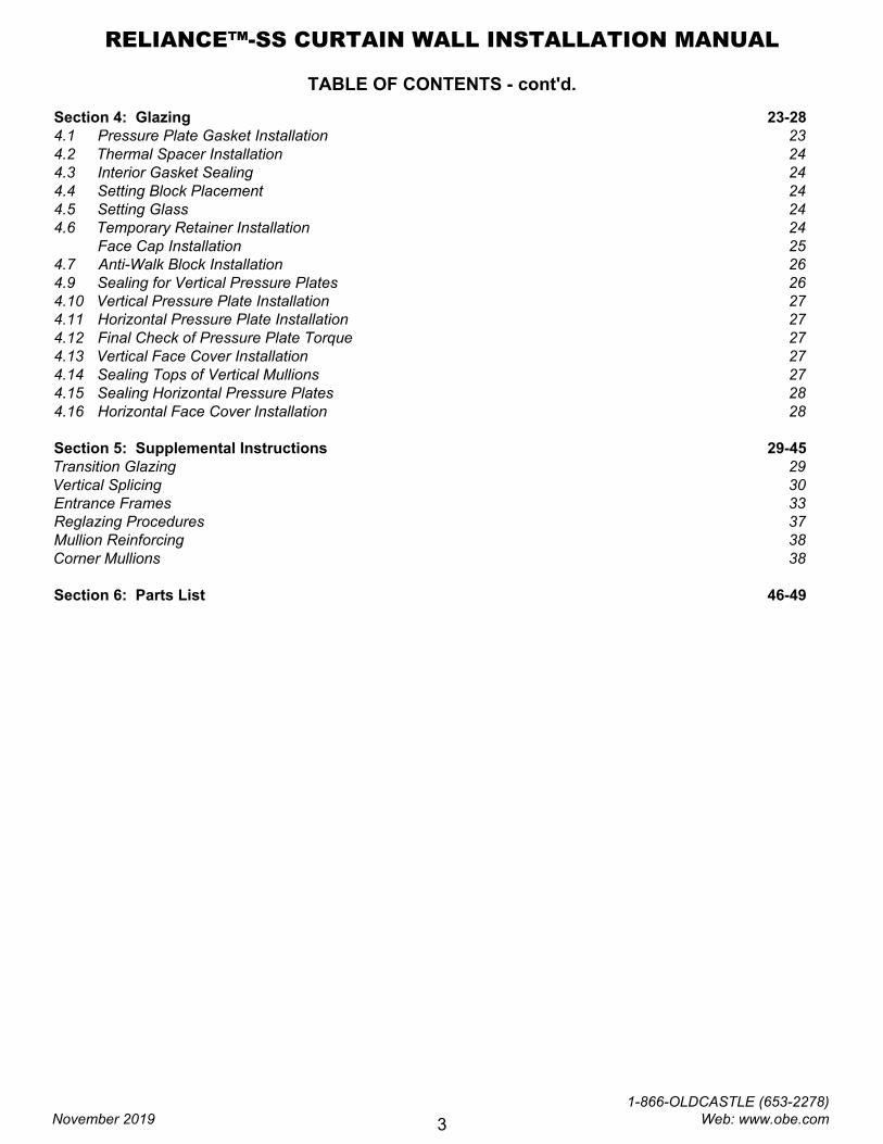
TABLE OF CONTENTS - cont'd.
Section 4: Glazing 23-28
4.1 Pressure Plate Gasket Installation 23
4.2 Thermal Spacer Installation 24
4.3 Interior Gasket Sealing 24
4.4 Setting Block Placement 24
4.5 Setting Glass 24
4.6 Temporary Retainer Installation 24
Face Cap Installation 25
4.7 Anti-Walk Block Installation 26
4.9 Sealing for Vertical Pressure Plates 26
4.10 Vertical Pressure Plate Installation 27
4.11 Horizontal Pressure Plate Installation 27
4.12 Final Check of Pressure Plate Torque 27
4.13 Vertical Face Cover Installation 27
4.14 Sealing Tops of Vertical Mullions 27
4.15 Sealing Horizontal Pressure Plates 28
4.16 Horizontal Face Cover Installation 28
Section 5: Supplemental Instructions 29-45
Transition Glazing 29
Vertical Splicing 30
Entrance Frames 33
Reglazing Procedures 37
Mullion Reinforcing 38
Corner Mullions 38
Section 6: Parts List 46-49
RELIANCE™-SS CURTAIN WALL INSTALLATION MANUAL
November 2019
1-866-OLDCASTLE (653-2278) Web: www.obe.com
3
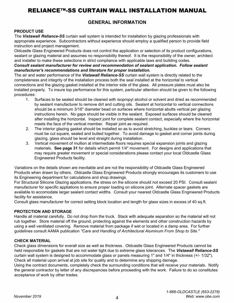
GENERAL INFORMATION
PRODUCT USE
The Vistawall Reliance-SS curtain wall system is intended for installation by glazing professionals with
appropriate experience. Subcontractors without experience should employ a qualified person to provide field
instruction and project management.
Oldcastle Glass Engineered Products does not control the application or selection of its product configurations,
sealant or glazing material and assumes no responsibility thereof. It is the responsibility of the owner, architect
and installer to make these selections in strict compliance with applicable laws and building codes.
Consult sealant manufacturer for review and recommendation of sealant application. Follow sealant
manufacturer's recommendations and literature for proper installation.
The air and water performance of the Vistawall Reliance-SS curtain wall system is directly related to the
completeness and integrity of the installation process both the seal installed at the horizontal to vertical
connections and the glazing gasket installed at the interior side of the glass. All pressure plates must also be
installed properly. To insure top performance for this system, particular attention should be given to the following
procedures:
1. Surfaces to be sealed should be cleaned with isopropyl alcohol or solvent and dried as recommended
by sealant manufacturer to remove dirt and cutting oils. Sealant at horizontal to vertical connections
should be a minimum 3/16" diameter bead on surfaces where horizontal abutts vertical per glazing
instructions herein. No gaps should be visible in the sealant. Exposed surfaces should be cleaned
after installing the horizontal. Inspect joint for complete sealant contact, especially where the horizontal
meets the face of the vertical member. Repair joint as required.
2. The interior glazing gasket should be installed so as to avoid stretching, buckles or tears. Corners
must be cut square, sealed and butted together. To avoid damage to gasket and corner joints during
glazing, glass should be level and straight during installation.
3. Vertical movement of mullion at intermediate floors requires special expansion joints and glazing
materials. See page 31 for details which permit 1/4" movement. For designs and applications that
may require greater movement or special considerations please contact your local Oldcastle Glass
Engineered Products facility.
Variations on the details shown are inevitable and are not the responsibility of Oldcastle Glass Engineered
Products when drawn by others. Oldcastle Glass Engineered Products strongly encourages its customers to use
its Engineering department for calculations and shop drawings.
For Structural Silicone Glazing applications, the stress on the silicone should not exceed 20 PSI. Consult sealant
manufacturer for specific appliations to ensure proper loading on silicone joint. Alternate spacer gaskets are
available to accomodate larger sealant contact widths. Consult your nearest Oldcastle Glass Engineered Products
facility for assistance.
Consult glass manufacturer for correct setting block location and length for glass sizes in excess of 40 sq.ft.
PROTECTION AND STORAGE
Handle all material carefully. Do not drop from the truck. Stack with adequate separation so the material will not
rub together. Store material off the ground, protecting against the elements and other construction hazards by
using a well ventilated covering. Remove material from package if wet or located in a damp area. For further
guidelines consult AAMA publication "Care and Handling of Architectural Aluminum From Shop to Site."
CHECK MATERIAL
Check glass dimensions for everall size as well as thickness. Oldcastle Glass Engineered Products cannot be
held responsible for gaskets that are not water tight due to extreme glass tolerances. The Vistawall Reliance-SS
curtain wall system is designed to accommodate glass or panels measuring 1" and 1/4" in thickness (+/- 1/32").
Check all material upon arrival at job site for quality and to determine any shipping damage.
Using the contract documents, completely check the surrounding conditions that will receive your materials. Notify
the general contractor by letter of any discrepancies before proceeding with the work. Failure to do so constitutes
acceptance of work by other trades.
RELIANCE™-SS CURTAIN WALL INSTALLATION MANUAL
November 2019
1-866-OLDCASTLE (653-2278) Web: www.obe.com
4
GENERAL INFORMATION
Check shop drawings, installation instructions, architectural drawings and shipping lists to become familiar with the
project. The shop drawings take precedence and include specific details for the project. The installation
instructions are of a general nature and cover the most common conditions. Due to varying job conditions all
sealant must be approved by the sealant manufacturer to insure it will perform per the conditions shown on the
instructions and shop drawings. The sealant must be compatible with all surfaces in which adhesion is required,
including other sealant surfaces. Use primers where directed by sealant manufacturer. Properly store sealant at
the recommended termperatures and check sealant for remainder of shelf life before using.
FIELD CONDITIONS
All material to be installed must be plumb, level and true. Aluminum to be placed in direct contact with masonry or
incompatible material should be isolated with a heavy coat of zinc chromate, bituminuous paint or non-metallic
material.
After sealant is set and a representative amount of the wall has been glazed (250 sq.ft. or more), perform a water
hose test in accordance with AAMA 501.2 specifications to check installation. On large projects the hose test
should be repeated during the glazing operation.
CLEANING MATERIALS
Cement, plaster terrazzo, alkaline and acid based materials used to clean masonry are very harmful to finishes.
Any residue should be removed with water and mild soap immediately or permanent staining will occur. A spot
test is recommended before any cleaning agent is used. Refer to the Architectural Finish Guide in the Detail
Catalog.
EXPANSION JOINTS
Expansion joints and perimeter joints shown in these instructions and in the shop drawings are shown at nominal
size. Actual dimensions may vary due to perimeter conditions and/or differences in metal temperature between
the time of fabrication and the time of installation. For example, a 12 foot unrestrained length of aluminum can
expand or contract 3/32" over a temperature change of 50 degrees F. Any movement potential should be
accounted for at the time of the installation.
SUGGESTIONS FOR IMPROVING SYSTEM THERMAL PERFORMANCE
To maintain or improve your wall installation the following items should be considered.
A. Blinds or drapes prevent warm air from adequately flowing over the window surface.
B. Warm air ventilators too far from the window will not adequately wash the window with air to prevent
condensation.
C. In extreme conditions the fan of the heating system should not cycle on and off, but should run
continuously.
D. Some heating systems have a water injection feature that can raise humidity levels. The higher the
humidity levels the more likely condensation or frost will form. Raising the temperatures and reducing
humidity will usually solve the problem.
E. On rare occasions an extremely cold storm may cause frost to appear on the glass framing. A space
heater and electric fan blowing along the plane of the window wall can reduce or eliminate this
temporary condition.
RELIANCE™-SS CURTAIN WALL INSTALLATION MANUAL
November 2019
1-866-OLDCASTLE (653-2278) Web: www.obe.com
5
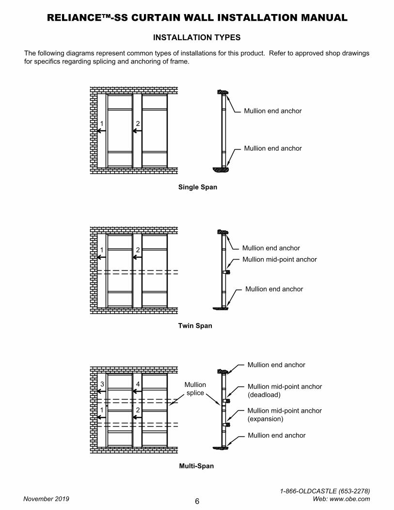
INSTALLATION TYPES
The following diagrams represent common types of installations for this product. Refer to approved shop drawings
for specifics regarding splicing and anchoring of frame.
Mullion end anchor
Mullion mid-point anchor
(deadload)
Mullion mid-point anchor
(expansion)
Mullion
splice
Mullion end anchor
Mullion end anchor
Mullion end anchor
Mullion mid-point anchor
Mullion end anchor
Mullion end anchor
Single Span
Twin Span
Multi-Span
1 2
1 2
1 2
3 4
RELIANCE™-SS CURTAIN WALL INSTALLATION MANUAL
November 2019
1-866-OLDCASTLE (653-2278) Web: www.obe.com
6
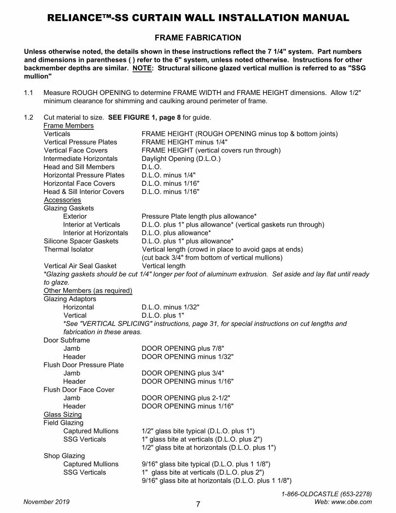
FRAME FABRICATION
Unless otherwise noted, the details shown in these instructions reflect the 7 1/4" system. Part numbers
and dimensions in parentheses ( ) refer to the 6" system, unless noted otherwise. Instructions for other
backmember depths are similar. NOTE: Structural silicone glazed vertical mullion is referred to as "SSG
mullion"
1.1 Measure ROUGH OPENING to determine FRAME WIDTH and FRAME HEIGHT dimensions. Allow 1/2"
minimum clearance for shimming and caulking around perimeter of frame.
1.2 Cut material to size. SEE FIGURE 1, page 8 for guide.
Frame Members
Verticals FRAME HEIGHT (ROUGH OPENING minus top & bottom joints)
Vertical Pressure Plates FRAME HEIGHT minus 1/4"
Vertical Face Covers FRAME HEIGHT (vertical covers run through)
Intermediate Horizontals Daylight Opening (D.L.O.)
Head and Sill Members D.L.O.
Horizontal Pressure Plates D.L.O. minus 1/4"
Horizontal Face Covers D.L.O. minus 1/16"
Head & Sill Interior Covers D.L.O. minus 1/16"
Accessories
Glazing Gaskets
Exterior Pressure Plate length plus allowance*
Interior at Verticals D.L.O. plus 1" plus allowance* (vertical gaskets run through)
Interior at Horizontals D.L.O. plus allowance*
Silicone Spacer Gaskets D.L.O. plus 1" plus allowance*
Thermal Isolator Vertical length (crowd in place to avoid gaps at ends)
(cut back 3/4" from bottom of vertical mullions)
Vertical Air Seal Gasket Vertical length
*Glazing gaskets should be cut 1/4" longer per foot of aluminum extrusion. Set aside and lay flat until ready
to glaze.
Other Members (as required)
Glazing Adaptors
Horizontal D.L.O. minus 1/32"
Vertical D.L.O. plus 1"
*See "VERTICAL SPLICING" instructions, page 31, for special instructions on cut lengths and
fabrication in these areas.
Door Subframe
Jamb
Header
Flush Door Pressure Plate
Jamb
Header
Flush Door Face Cover
Jamb
Header
Glass Sizing
Field Glazing
Captured Mullions
SSG Verticals
Shop Glazing
Captured Mullions
SSG Verticals
DOOR OPENING plus 7/8"
DOOR OPENING minus 1/32"
DOOR OPENING plus 3/4"
DOOR OPENING minus 1/16"
DOOR OPENING plus 2-1/2"
DOOR OPENING minus 1/16"
1/2" glass bite typical (D.L.O. plus 1")
1" glass bite at verticals (D.L.O. plus 2")
1/2" glass bite at horizontals (D.L.O. plus 1")
9/16" glass bite typical (D.L.O. plus 1 1/8")
1" glass bite at verticals (D.L.O. plus 2")
9/16" glass bite at horizontals (D.L.O. plus 1 1/8")
RELIANCE™-SS CURTAIN WALL INSTALLATION MANUAL
November 2019
1-866-OLDCASTLE (653-2278) Web: www.obe.com
7
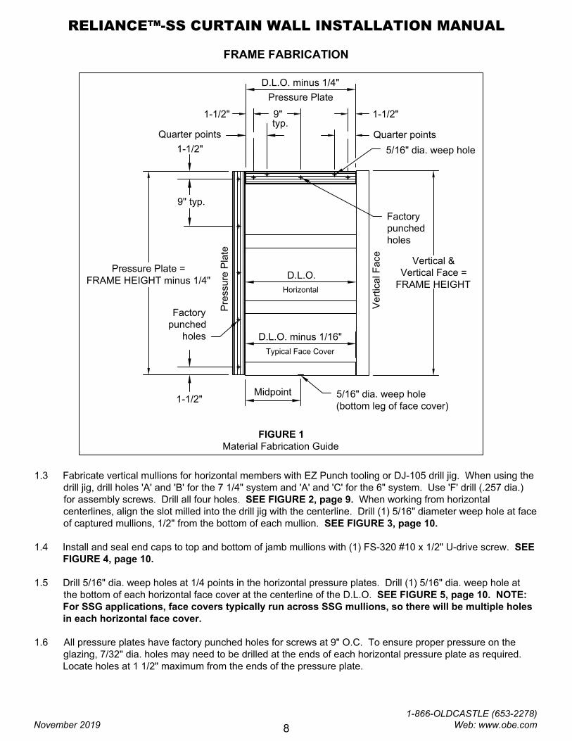
typ.
Quarter points
D.L.O.
Horizontal
Midpoint
5/16" dia. weep hole
(bottom leg of face cover)
Typical Face Cover
5/16" dia. weep hole
9" 1-1/2"1-1/2"
1-1/2"
9" typ.
1-1/2"
D.L.O. minus 1/16"
D.L.O. minus 1/4"
Quarter points
Pressure Plate =
FRAME HEIGHT minus 1/4"
Vertical &
Vertical Face =
FRAME HEIGHT
Pre
ssu
re
P
la
te
Ve
rtica
l F
ace
Factory
punched
holes
Pressure Plate
Factory
punched
holes
FIGURE 1
Material Fabrication Guide
FRAME FABRICATION
1.3 Fabricate vertical mullions for horizontal members with EZ Punch tooling or DJ-105 drill jig. When using the
drill jig, drill holes 'A' and 'B' for the 7 1/4" system and 'A' and 'C' for the 6" system. Use 'F' drill (.257 dia.)
for assembly screws. Drill all four holes. SEE FIGURE 2, page 9. When working from horizontal
centerlines, align the slot milled into the drill jig with the centerline. Drill (1) 5/16" diameter weep hole at face
of captured mullions, 1/2" from the bottom of each mullion. SEE FIGURE 3, page 10.
1.4 Install and seal end caps to top and bottom of jamb mullions with (1) FS-320 #10 x 1/2" U-drive screw. SEE
FIGURE 4, page 10.
1.5 Drill 5/16" dia. weep holes at 1/4 points in the horizontal pressure plates. Drill (1) 5/16" dia. weep hole at
the bottom of each horizontal face cover at the centerline of the D.L.O. SEE FIGURE 5, page 10. NOTE:
For SSG applications, face covers typically run across SSG mullions, so there will be multiple holes
in each horizontal face cover.
1.6 All pressure plates have factory punched holes for screws at 9" O.C. To ensure proper pressure on the
glazing, 7/32" dia. holes may need to be drilled at the ends of each horizontal pressure plate as required.
Locate holes at 1 1/2" maximum from the ends of the pressure plate.
RELIANCE™-SS CURTAIN WALL INSTALLATION MANUAL
November 2019
1-866-OLDCASTLE (653-2278) Web: www.obe.com
8
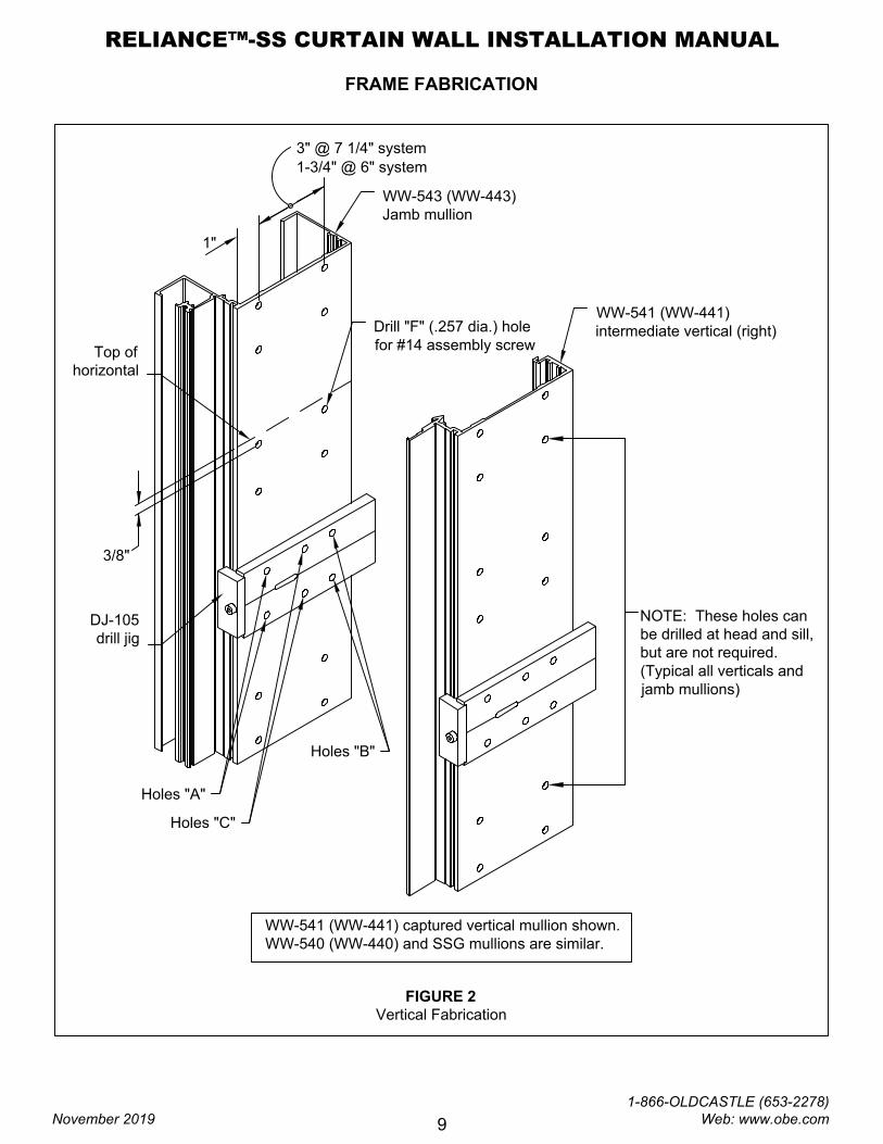
FRAME FABRICATION
1"
1-3/4" @ 6" system
Drill "F" (.257 dia.) hole
for #14 assembly screw
NOTE: These holes can
be drilled at head and sill,
but are not required.
(Typical all verticals and
jamb mullions)
WW-541 (WW-441) captured vertical mullion shown.
WW-540 (WW-440) and SSG mullions are similar.
FIGURE 2
Vertical Fabrication
DJ-105
drill jig
Holes "A"
Holes "B"
WW-543 (WW-443)
Jamb mullion
WW-541 (WW-441)
intermediate vertical (right)
Top of
horizontal
3/8"
Holes "C"
3" @ 7 1/4" system
RELIANCE™-SS CURTAIN WALL INSTALLATION MANUAL
November 2019
1-866-OLDCASTLE (653-2278) Web: www.obe.com
9
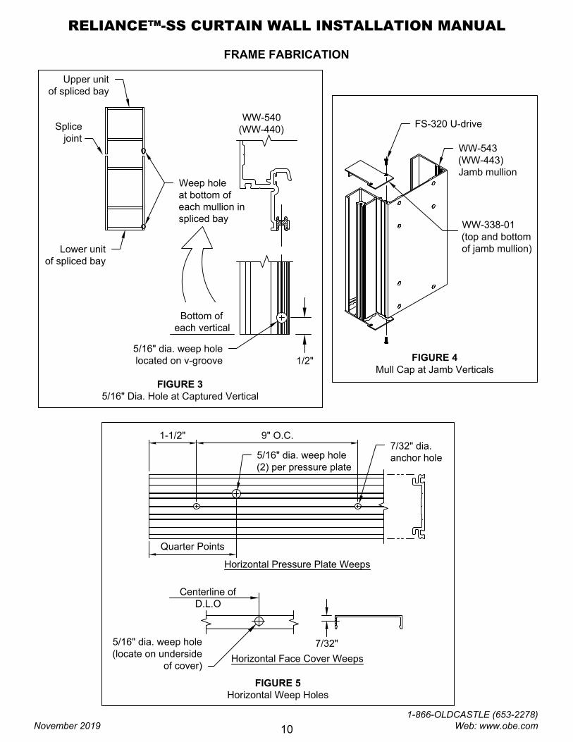
FRAME FABRICATION
FIGURE 3
5/16" Dia. Hole at Captured Vertical
1/2"
WW-540
(WW-440)
Bottom of
each vertical
FIGURE 4
Mull Cap at Jamb Verticals
WW-543
(WW-443)
Jamb mullion
WW-338-01
(top and bottom
of jamb mullion)
FS-320 U-drive
7/32"
Centerline of
D.L.O
5/16" dia. weep hole
(locate on underside
of cover)
Horizontal Face Cover Weeps
FIGURE 5
Horizontal Weep Holes
Horizontal Pressure Plate Weeps
1-1/2"
Quarter Points
9" O.C.
5/16" dia. weep hole
located on v-groove
7/32" dia.
anchor hole
5/16" dia. weep hole
(2) per pressure plate
Upper unit
of spliced bay
Lower unit
of spliced bay
Weep hole
at bottom of
each mullion in
spliced bay
Splice
joint
RELIANCE™-SS CURTAIN WALL INSTALLATION MANUAL
November 2019
1-866-OLDCASTLE (653-2278) Web: www.obe.com
10
FRAME FABRICATION
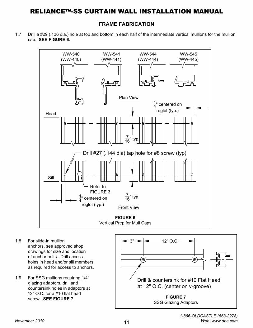
1.7 Drill a #29 (.136 dia.) hole at top and bottom in each half of the intermediate vertical mullions for the mullion
cap. SEE FIGURE 6.
FIGURE 6
Vertical Prep for Mull Caps
WW-540
(WW-440)
Sill
WW-541
(WW-441)
WW-544
(WW-444)
WW-545
(WW-445)
7
16
" typ.
1
4
" centered on
reglet (typ.)
Drill #27 (.144 dia) tap hole for #8 screw (typ)
1
4
" centered on
reglet (typ.)
7
16
" typ.
Head
1.8 For slide-in mullion
anchors, see approved shop
drawings for size and location
of anchor bolts. Drill access
holes in head and/or sill members
as required for access to anchors.
1.9 For SSG mullions requiring 1/4"
glazing adaptors, drill and
countersink holes in adaptors at
12" O.C. for a #10 flat head
screw. SEE FIGURE 7.
Refer to
FIGURE 3
Plan View
Front View
FIGURE 7
SSG Glazing Adaptors
Drill & countersink for #10 Flat Head
at 12" O.C. (center on v-groove)
3" 12" O.C.
RELIANCE™-SS CURTAIN WALL INSTALLATION MANUAL
November 2019
1-866-OLDCASTLE (653-2278) Web: www.obe.com
11
FRAME ASSEMBLY
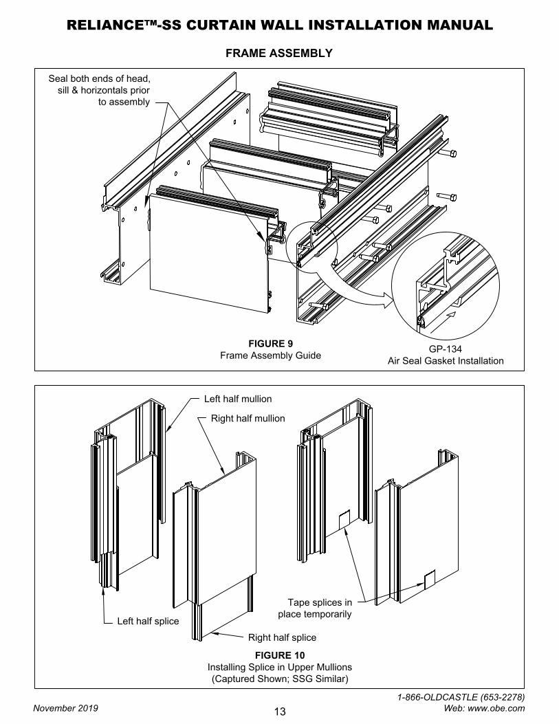
2.1 Starting with the left jamb of the opening,lay out verticals and horizontals for assembly of the bay. SEE
FIGURE 8.
2.2 Apply sealant to ends of horizontals prior to attaching to verticals. Attach to verticals with FS-8 #14 x 1" Hex
Head screw. Three screws are required at each head and sill; four are required at intermediate horizontals.
SEE FIGURE 9, page 13. Tool excess sealant at horizontal-to-vertical joints.
2.3 Install GP-134 bulb gasket into race at center of captured and SSG mullions. Crimp ends of mullion to lock
into position. SEE FIGURE 9, page 13.
2.4 If mullions are spliced, slide splice sleeves into the bottom of the upper bay mullion. Secure with tape. SEE
FIGURE 10, page 13. Install one (1) FS-322 #14 x 1" TEK screw into the top of the lower bay mullion to act
as a stop screw for the splices during frame installation. SEE FIGURE 11, page 14.
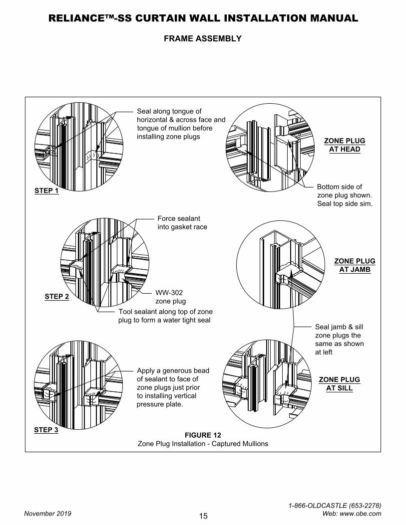
2.5 After bay is assembled, apply sealant to all contact surfaces on vertical and horizontal mullions where the
zone plugs will be installed (captured mullions only). Apply sealant to horizontal tongue receptor on zone
plug and install at the end of each horizontal, head and sill. Tool any excess sealant around front end of
zone plug where thermal isolator abuts the zone plug. Tool sealant in the glazing pockets to ensure a
watertight fit. SEE FIGURE 12, page 15.
FIGURE 8
Frame Assembly Guide
RELIANCE™-SS CURTAIN WALL INSTALLATION MANUAL
November 2019
1-866-OLDCASTLE (653-2278) Web: www.obe.com
12
FRAME ASSEMBLY
FIGURE 10
Installing Splice in Upper Mullions
(Captured Shown; SSG Similar)
Right half splice
Left half splice
Right half mullion
Left half mullion
Tape splices in
place temporarily
FIGURE 9
Frame Assembly Guide
Seal both ends of head,
sill & horizontals prior
to assembly
GP-134
Air Seal Gasket Installation
RELIANCE™-SS CURTAIN WALL INSTALLATION MANUAL
November 2019
1-866-OLDCASTLE (653-2278) Web: www.obe.com
13
FRAME ASSEMBLY
FIGURE 11
Splice Stop Screw
3-3
/4
"
Top of
Lower Mullion
FS-322 #14 x 1" TEK
2.6 For field glazing, go to step 2.7. If pre-glazing glass, refer to steps 2.8 and 2.9.
2.7 Install interior gaskets, running the vertical gaskets through and abutting the horizontal gaskets with a slight
bevel. For SSG mullions, install GP-105 spacer gasket on the inner most reglets of the mullion. DO NOT
SEAL GASKETS UNTIL JUST PRIOR TO SETTING GLASS. Proceed to FRAME INSTALLATION, page
18.
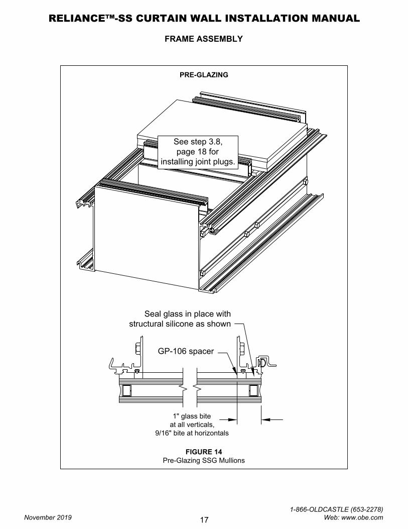
2.8 If pre-glazing any part of the bay, install the GP-106 interior (frame) gasket in the openings to be pre-glazed.
Vertical gaskets run through.
NOTE: The Reliance-SS system is designed for limited pre-glazing. It is ideal for pre-glazing
spandrel lites. Consider weight, staging and handling issues when determining whether pre-glazing
is the correct method for a given application.
2.9 To pre-glaze lites, make sure frame is set glass side up, squared and level. Thoroughly clean edges of
glass and frame where silicone will be contacting. Seal around edges of glass. SEE FIGURE 13, page 16
for captured mullions and FIGURE 14, page 17 for SSG mullions. Tool sealant and set frame aside while
silicone cures.
2.10 Repeat steps 2.1 to 2.9 until all bays have been assembled.
RELIANCE™-SS CURTAIN WALL INSTALLATION MANUAL
November 2019
1-866-OLDCASTLE (653-2278) Web: www.obe.com
14
FRAME ASSEMBLY
STEP 1
STEP 2
STEP 3
ZONE PLUG
AT HEAD
ZONE PLUG
AT JAMB
ZONE PLUG
AT SILL
FIGURE 12
Zone Plug Installation - Captured Mullions
Seal along tongue of
horizontal & across face and
tongue of mullion before
installing zone plugs
Force sealant
into gasket race
Tool sealant along top of zone
plug to form a water tight seal
Apply a generous bead
of sealant to face of
zone plugs just prior
to installing vertical
pressure plate.
WW-302
zone plug
Bottom side of
zone plug shown.
Seal top side sim.
Seal jamb & sill
zone plugs the
same as shown
at left
RELIANCE™-SS CURTAIN WALL INSTALLATION MANUAL
November 2019
1-866-OLDCASTLE (653-2278) Web: www.obe.com
15
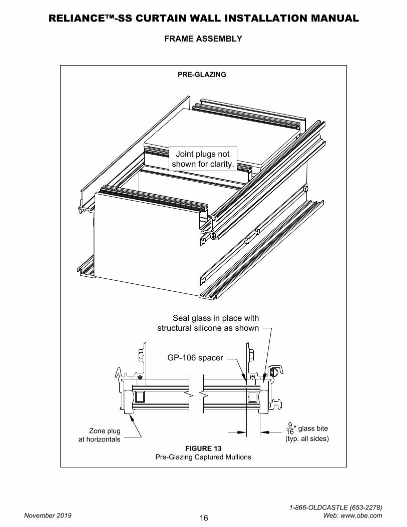
FRAME ASSEMBLY
FIGURE 13
Pre-Glazing Captured Mullions
9
16
" glass bite
(typ. all sides)
GP-106 spacer
Seal glass in place with
structural silicone as shown
Zone plug
at horizontals
PRE-GLAZING
Joint plugs not
shown for clarity.
RELIANCE™-SS CURTAIN WALL INSTALLATION MANUAL
November 2019
1-866-OLDCASTLE (653-2278) Web: www.obe.com
16
FRAME ASSEMBLY
FIGURE 14
Pre-Glazing SSG Mullions
1" glass bite
at all verticals,
9/16" bite at horizontals
GP-106 spacer
Seal glass in place with
structural silicone as shown
PRE-GLAZING
See step 3.8,
page 18 for
installing joint plugs.
RELIANCE™-SS CURTAIN WALL INSTALLATION MANUAL
November 2019
1-866-OLDCASTLE (653-2278) Web: www.obe.com
17
FRAME INSTALLATION
Anchor type and sizes vary per job requirements. Details shown in these instructions are to be used as a
guide only. Refer to approved shop drawings for actual conditions.
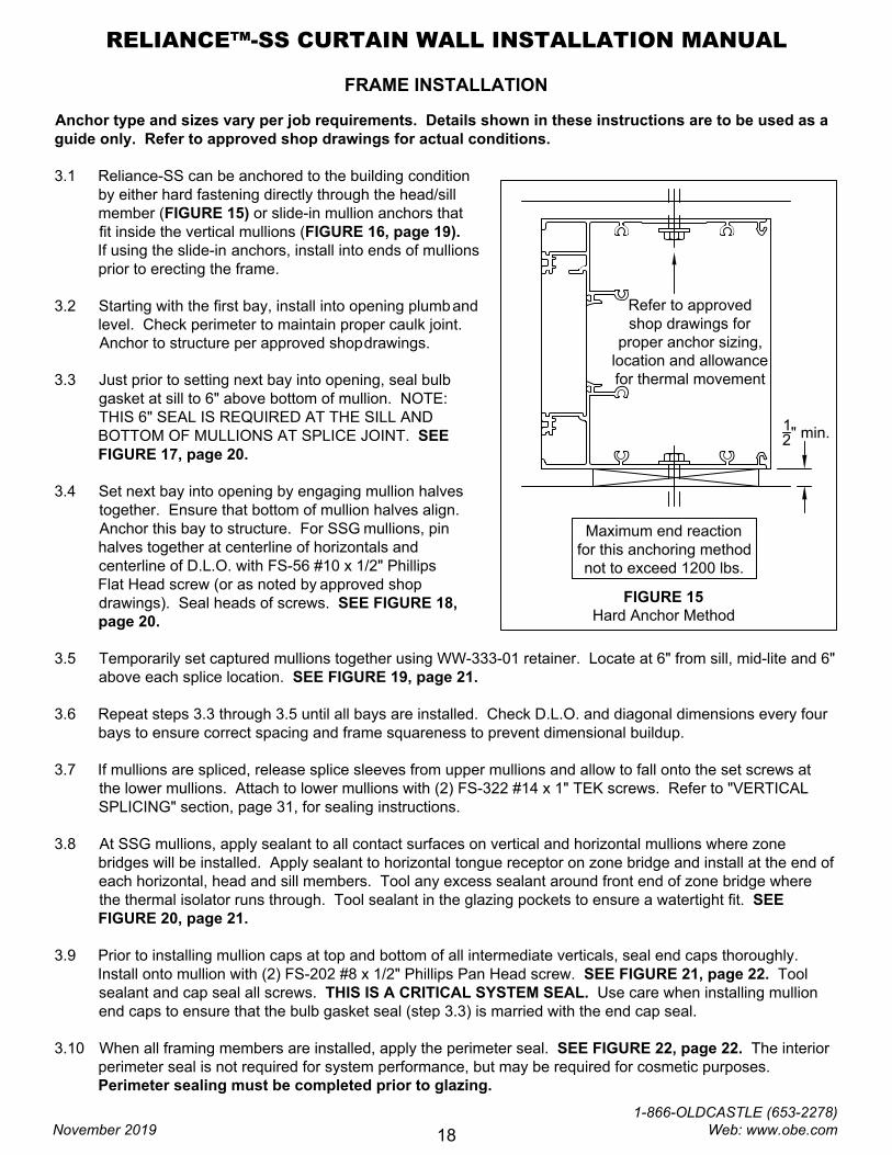
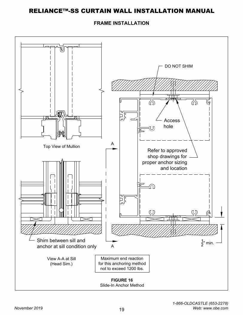
3.1 Reliance-SS can be anchored to the building condition
by either hard fastening directly through the head/sill
member (FIGURE 15) or slide-in mullion anchors that
fit inside the vertical mullions (FIGURE 16, page 19).
If using the slide-in anchors, install into ends of mullions
prior to erecting the frame.
3.2 Starting with the first bay, install into opening plumband
level. Check perimeter to maintain proper caulk joint.
Anchor to structure per approved shopdrawings.
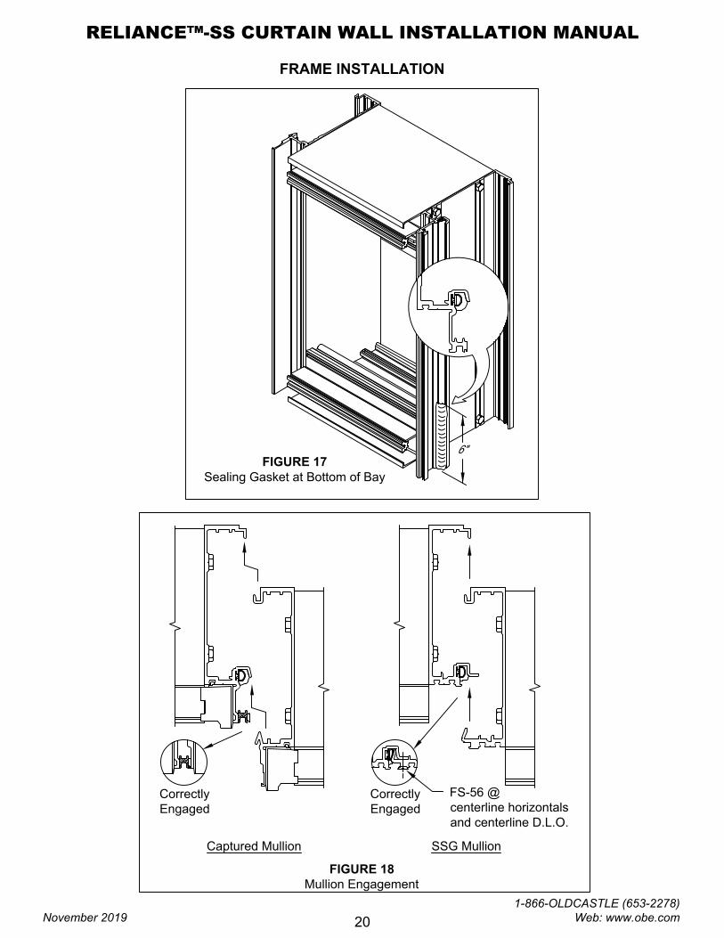
3.3 Just prior to setting next bay into opening, seal bulb
gasket at sill to 6" above bottom of mullion. NOTE:
THIS 6" SEAL IS REQUIRED AT THE SILL AND
BOTTOM OF MULLIONS AT SPLICE JOINT. SEE
FIGURE 17, page 20.
3.4 Set next bay into opening by engaging mullion halves
together. Ensure that bottom of mullion halves align.
Anchor this bay to structure. For SSG mullions, pin
halves together at centerline of horizontals and
centerline of D.L.O. with FS-56 #10 x 1/2" Phillips
Flat Head screw (or as noted by approved shop
drawings). Seal heads of screws. SEE FIGURE 18,
page 20.
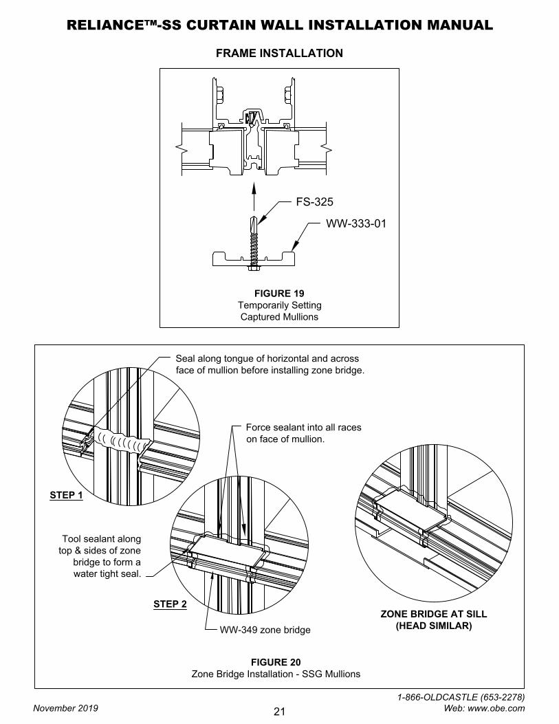
3.5 Temporarily set captured mullions together using WW-333-01 retainer. Locate at 6" from sill, mid-lite and 6"
above each splice location. SEE FIGURE 19, page 21.
3.6 Repeat steps 3.3 through 3.5 until all bays are installed. Check D.L.O. and diagonal dimensions every four
bays to ensure correct spacing and frame squareness to prevent dimensional buildup.
3.7 If mullions are spliced, release splice sleeves from upper mullions and allow to fall onto the set screws at
the lower mullions. Attach to lower mullions with (2) FS-322 #14 x 1" TEK screws. Refer to "VERTICAL
SPLICING" section, page 31, for sealing instructions.
3.8 At SSG mullions, apply sealant to all contact surfaces on vertical and horizontal mullions where zone
bridges will be installed. Apply sealant to horizontal tongue receptor on zone bridge and install at the end of
each horizontal, head and sill members. Tool any excess sealant around front end of zone bridge where
the thermal isolator runs through. Tool sealant in the glazing pockets to ensure a watertight fit. SEE
FIGURE 20, page 21.
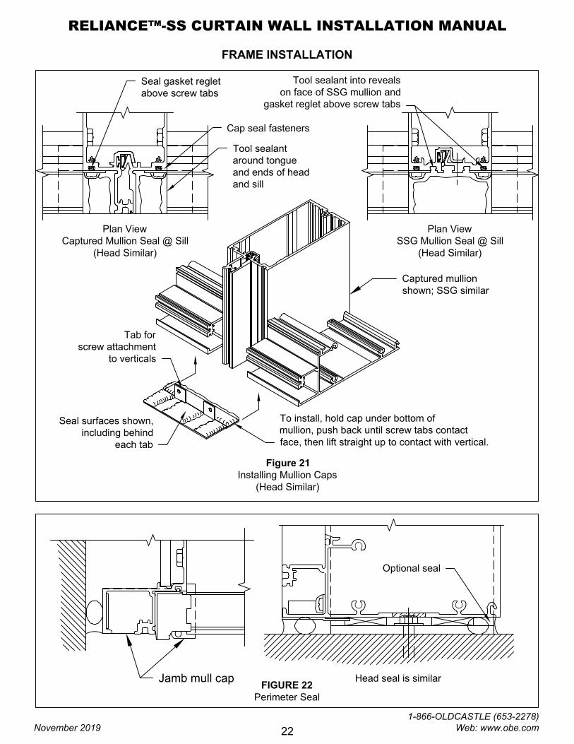
3.9 Prior to installing mullion caps at top and bottom of all intermediate verticals, seal end caps thoroughly.
Install onto mullion with (2) FS-202 #8 x 1/2" Phillips Pan Head screw. SEE FIGURE 21, page 22. Tool
sealant and cap seal all screws. THIS IS A CRITICAL SYSTEM SEAL. Use care when installing mullion
end caps to ensure that the bulb gasket seal (step 3.3) is married with the end cap seal.
3.10 When all framing members are installed, apply the perimeter seal. SEE FIGURE 22, page 22. The interior
perimeter seal is not required for system performance, but may be required for cosmetic purposes.
Perimeter sealing must be completed prior to glazing.
FIGURE 15
Hard Anchor Method
Refer to approved
shop drawings for
proper anchor sizing,
location and allowance
for thermal movement
1
2
" min.
Maximum end reaction
for this anchoring method
not to exceed 1200 lbs.
RELIANCE™-SS CURTAIN WALL INSTALLATION MANUAL
November 2019
1-866-OLDCASTLE (653-2278) Web: www.obe.com
18
FRAME INSTALLATION
Refer to approved
shop drawings for
proper anchor sizing
and location
1
2
" min.
FIGURE 16
Slide-In Anchor Method
Maximum end reaction
for this anchoring method
not to exceed 1200 lbs.
Access
hole
Shim between sill and
anchor at sill condition only
Top View of Mullion
A
A
View A-A at Sill
(Head Sim.)
DO NOT SHIM
RELIANCE™-SS CURTAIN WALL INSTALLATION MANUAL
November 2019
1-866-OLDCASTLE (653-2278) Web: www.obe.com
19
FRAME INSTALLATION
FIGURE 18
Mullion Engagement
Captured Mullion SSG Mullion
Correctly
Engaged
Correctly
Engaged
FS-56 @
centerline horizontals
and centerline D.L.O.
FIGURE 17
Sealing Gasket at Bottom of Bay
6"
RELIANCE™-SS CURTAIN WALL INSTALLATION MANUAL
November 2019
1-866-OLDCASTLE (653-2278) Web: www.obe.com
20
FRAME INSTALLATION
FIGURE 19
Temporarily Setting
Captured Mullions
FS-325
WW-333-01
WW-349 zone bridge
Force sealant into all races
on face of mullion.
Tool sealant along
top & sides of zone
bridge to form a
water tight seal.
Seal along tongue of horizontal and across
face of mullion before installing zone bridge.
STEP 1
STEP 2
ZONE BRIDGE AT SILL
(HEAD SIMILAR)
FIGURE 20
Zone Bridge Installation - SSG Mullions
RELIANCE™-SS CURTAIN WALL INSTALLATION MANUAL
November 2019
1-866-OLDCASTLE (653-2278) Web: www.obe.com
21
FRAME INSTALLATION
FIGURE 22
Perimeter Seal
Optional seal
Head seal is similarJamb mull cap
Figure 21
Installing Mullion Caps
(Head Similar)
Plan View
Captured Mullion Seal @ Sill
(Head Similar)
Plan View
SSG Mullion Seal @ Sill
(Head Similar)
Tab for
screw attachment
to verticals
Seal surfaces shown,
including behind
each tab
Tool sealant
around tongue
and ends of head
and sill
Cap seal fasteners
Tool sealant into reveals
on face of SSG mullion and
gasket reglet above screw tabs
Seal gasket reglet
above screw tabs
To install, hold cap under bottom of
mullion, push back until screw tabs contact
face, then lift straight up to contact with vertical.
Captured mullion
shown; SSG similar
RELIANCE™-SS CURTAIN WALL INSTALLATION MANUAL
November 2019
1-866-OLDCASTLE (653-2278) Web: www.obe.com
22
GLAZING
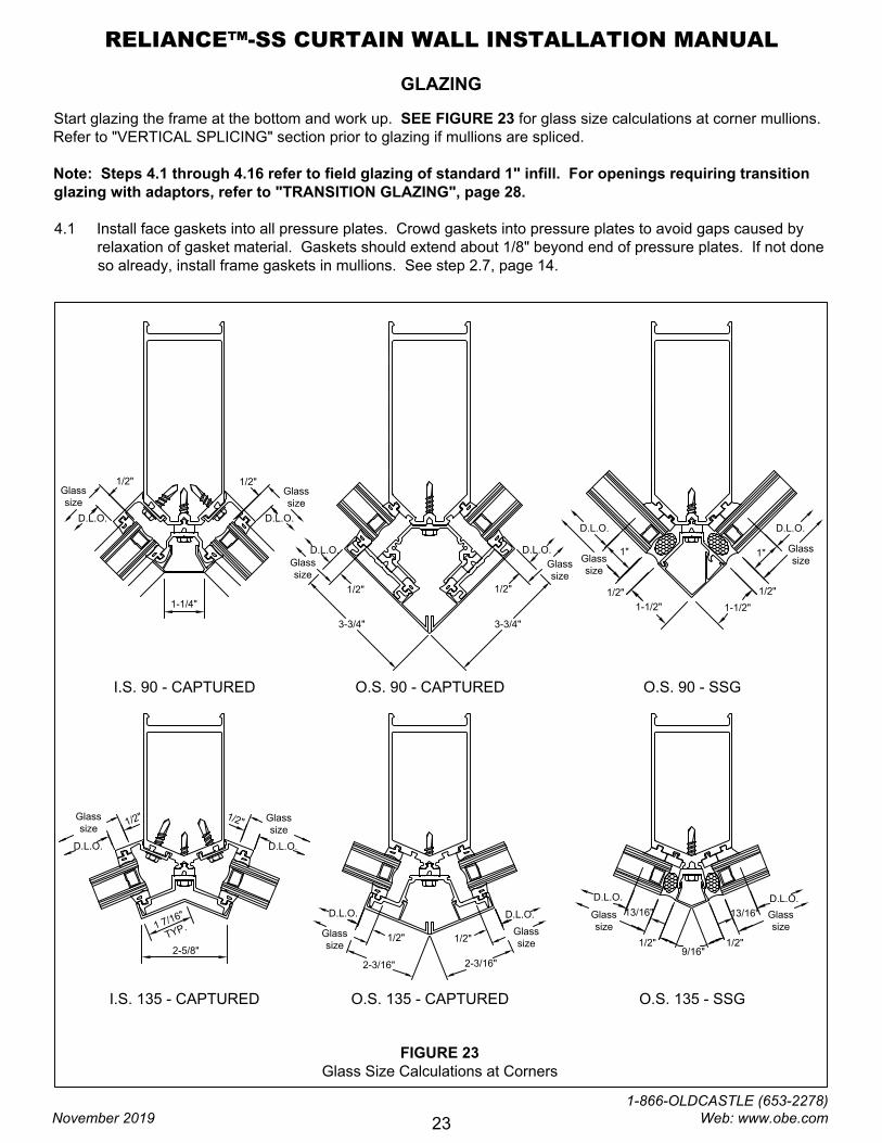
Start glazing the frame at the bottom and work up. SEE FIGURE 23 for glass size calculations at corner mullions.
Refer to "VERTICAL SPLICING" section prior to glazing if mullions are spliced.
Note: Steps 4.1 through 4.16 refer to field glazing of standard 1" infill. For openings requiring transition
glazing with adaptors, refer to "TRANSITION GLAZING", page 28.
4.1 Install face gaskets into all pressure plates. Crowd gaskets into pressure plates to avoid gaps caused by
relaxation of gasket material. Gaskets should extend about 1/8" beyond end of pressure plates. If not done
so already, install frame gaskets in mullions. See step 2.7, page 14.
FIGURE 23
Glass Size Calculations at Corners
1/2"
D.L.O.
Glass
size
1/2"
D.L.O.
1-1/4"
3-3/4"
D.L.O.
1/2"
3-3/4"
1/2"
1"
1-1/2"
D.L.O.D.L.O.
1"
1/2"
1
7
/
1
6
"
T
Y
P
.
2-5/8"
1
/
2
"
D.L.O.
1
/
2
"
D.L.O.
1/2"
D.L.O.
2-3/16"
1/2"
D.L.O.
2-3/16"
I.S. 90 - CAPTURED O.S. 90 - CAPTURED O.S. 90 - SSG
I.S. 135 - CAPTURED O.S. 135 - CAPTURED O.S. 135 - SSG
1/2"
D.L.O.
Glass
size
1-1/2"
D.L.O.
1/2"
9/16"
13/16"
D.L.O.
13/16"
1/2"
Glass
size
Glass
size
Glass
size
Glass
size
Glass
size
Glass
size
Glass
size
Glass
size
Glass
size
Glass
size
RELIANCE™-SS CURTAIN WALL INSTALLATION MANUAL
November 2019
1-866-OLDCASTLE (653-2278) Web: www.obe.com
23
GLAZING
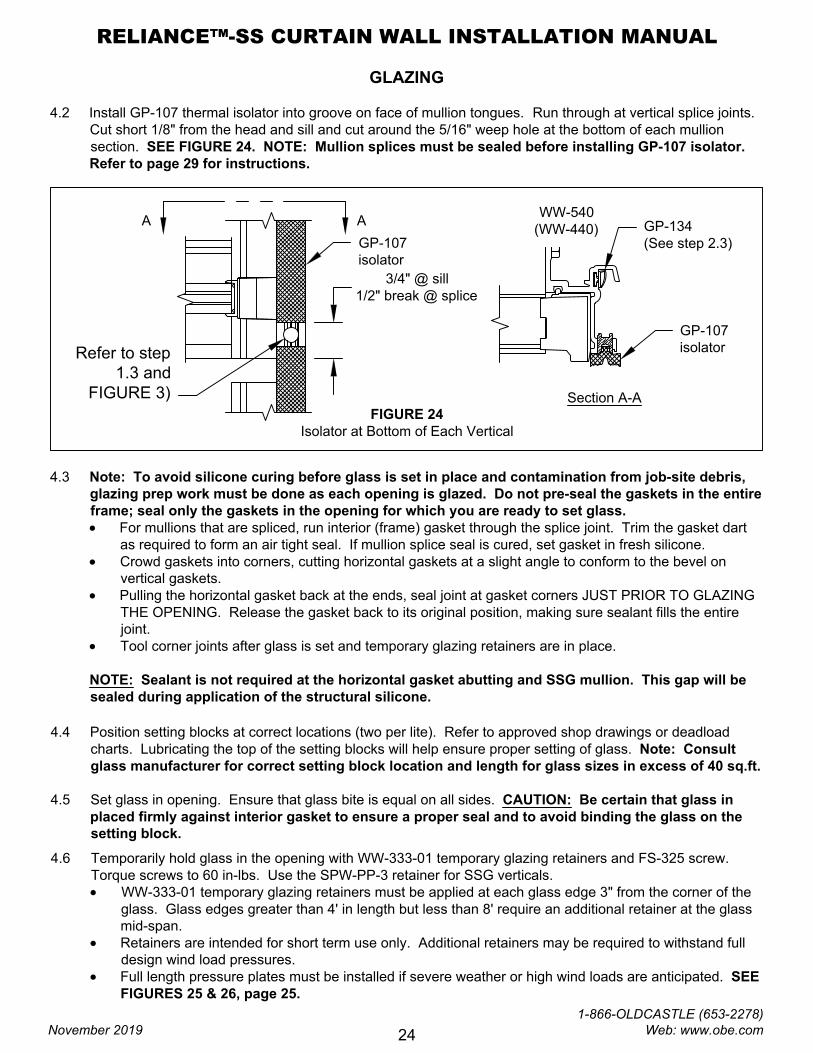
4.2 Install GP-107 thermal isolator into groove on face of mullion tongues. Run through at vertical splice joints.
Cut short 1/8" from the head and sill and cut around the 5/16" weep hole at the bottom of each mullion
section. SEE FIGURE 24. NOTE: Mullion splices must be sealed before installing GP-107 isolator.
Refer to page 29 for instructions.
FIGURE 24
Isolator at Bottom of Each Vertical
WW-540
(WW-440)
3/4" @ sill
1/2" break @ splice
Refer to step
1.3 and
FIGURE 3)
GP-134
(See step 2.3)GP-107
isolator
A A
Section A-A
GP-107
isolator
4.4 Position setting blocks at correct locations (two per lite). Refer to approved shop drawings or deadload
charts. Lubricating the top of the setting blocks will help ensure proper setting of glass. Note: Consult
glass manufacturer for correct setting block location and length for glass sizes in excess of 40 sq.ft.
4.5 Set glass in opening. Ensure that glass bite is equal on all sides. CAUTION: Be certain that glass in
placed firmly against interior gasket to ensure a proper seal and to avoid binding the glass on the
setting block.
4.3 Note: To avoid silicone curing before glass is set in place and contamination from job-site debris,
glazing prep work must be done as each opening is glazed. Do not pre-seal the gaskets in the entire
frame; seal only the gaskets in the opening for which you are ready to set glass.
· For mullions that are spliced, run interior (frame) gasket through the splice joint. Trim the gasket dart
as required to form an air tight seal. If mullion splice seal is cured, set gasket in fresh silicone.
· Crowd gaskets into corners, cutting horizontal gaskets at a slight angle to conform to the bevel on
vertical gaskets.
· Pulling the horizontal gasket back at the ends, seal joint at gasket corners JUST PRIOR TO GLAZING
THE OPENING. Release the gasket back to its original position, making sure sealant fills the entire
joint.
· Tool corner joints after glass is set and temporary glazing retainers are in place.
NOTE: Sealant is not required at the horizontal gasket abutting and SSG mullion. This gap will be
sealed during application of the structural silicone.
4.6 Temporarily hold glass in the opening with WW-333-01 temporary glazing retainers and FS-325 screw.
Torque screws to 60 in-lbs. Use the SPW-PP-3 retainer for SSG verticals.
· WW-333-01 temporary glazing retainers must be applied at each glass edge 3" from the corner of the
glass. Glass edges greater than 4' in length but less than 8' require an additional retainer at the glass
mid-span.
· Retainers are intended for short term use only. Additional retainers may be required to withstand full
design wind load pressures.
· Full length pressure plates must be installed if severe weather or high wind loads are anticipated. SEE
FIGURES 25 & 26, page 25.
RELIANCE™-SS CURTAIN WALL INSTALLATION MANUAL
November 2019
1-866-OLDCASTLE (653-2278) Web: www.obe.com
24
9/32"
Vertical Face Covers:
Face Cover Fabrication
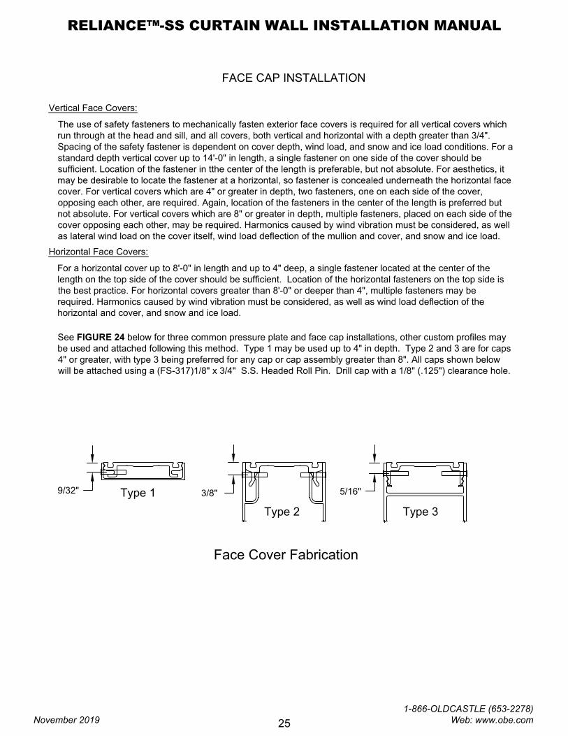
FACE CAP INSTALLATION
The use of safety fasteners to mechanically fasten exterior face covers is required for all vertical covers which
run through at the head and sill, and all covers, both vertical and horizontal with a depth greater than 3/4".
Spacing of the safety fastener is dependent on cover depth, wind load, and snow and ice load conditions. For a
standard depth vertical cover up to 14'-0" in length, a single fastener on one side of the cover should be
sufficient. Location of the fastener in tthe center of the length is preferable, but not absolute. For aesthetics, it
may be desirable to locate the fastener at a horizontal, so fastener is concealed underneath the horizontal face
cover. For vertical covers which are 4" or greater in depth, two fasteners, one on each side of the cover,
opposing each other, are required. Again, location of the fasteners in the center of the length is preferred but
not absolute. For vertical covers which are 8" or greater in depth, multiple fasteners, placed on each side of the
cover opposing each other, may be required. Harmonics caused by wind vibration must be considered, as well
as lateral wind load on the cover itself, wind load deflection of the mullion and cover, and snow and ice load.
Horizontal Face Covers:
For a horizontal cover up to 8'-0" in length and up to 4" deep, a single fastener located at the center of the
length on the top side of the cover should be sufficient. Location of the horizontal fasteners on the top side is
the best practice. For horizontal covers greater than 8'-0" or deeper than 4", multiple fasteners may be
required. Harmonics caused by wind vibration must be considered, as well as wind load deflection of the
horizontal and cover, and snow and ice load.
3/8"
5/16"
See FIGURE 24 below for three common pressure plate and face cap installations, other custom profiles may
be used and attached following this method. Type 1 may be used up to 4" in depth. Type 2 and 3 are for caps
4" or greater, with type 3 being preferred for any cap or cap assembly greater than 8". All caps shown below
will be attached using a (FS-317)1/8" x 3/4" S.S. Headed Roll Pin. Drill cap with a 1/8" (.125") clearance hole.
Type 1
Type 2 Type 3
RELIANCE™-SS CURTAIN WALL INSTALLATION MANUAL
November 2019
1-866-OLDCASTLE (653-2278) Web: www.obe.com
25
GLAZING
WW-300 zone plug
see FIGURE 12 for
sealant notes
GP-109 setting block
(2) per D.L.O, locate
at 1/4 points
WW-333-01 temporary glazing retainer.
Locate at 3" from edge of
glass. Additional
retainers may be
required based
on field conditions
and glass size.
FS-325
(1) per retainer
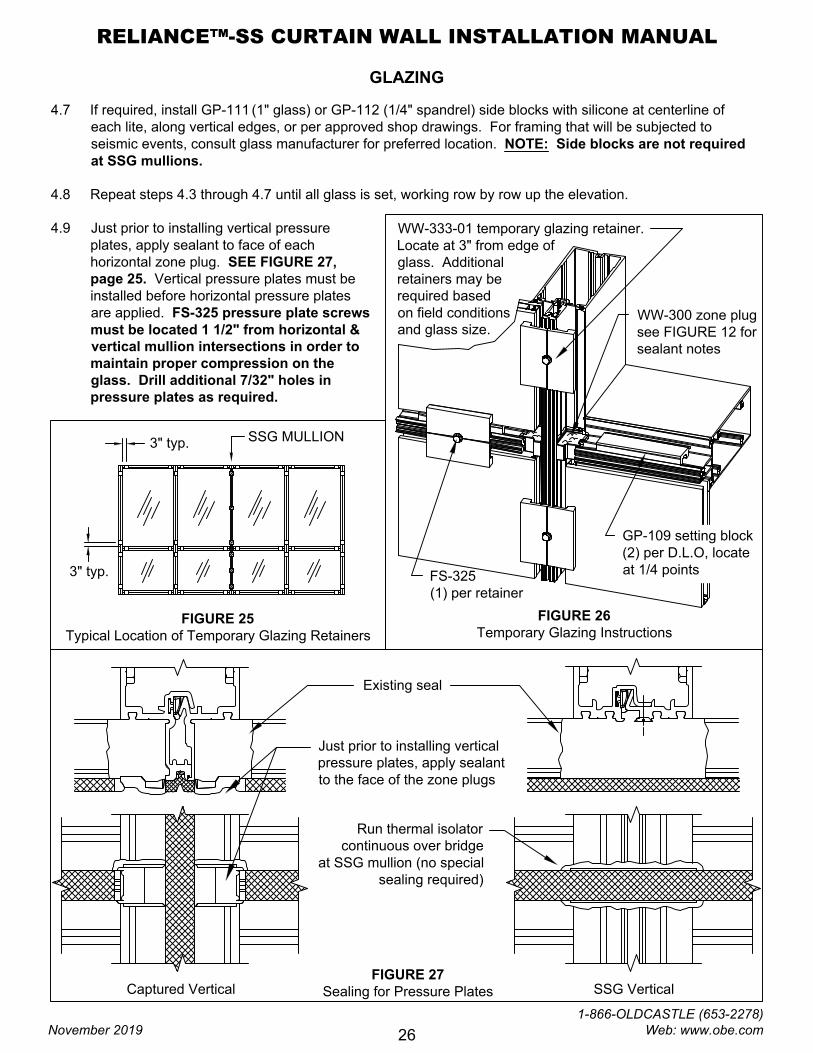
FIGURE 25
Typical Location of Temporary Glazing Retainers
3" typ.
3" typ.
SSG MULLION
FIGURE 26
Temporary Glazing Instructions
FIGURE 27
Sealing for Pressure Plates
Existing seal
Captured Vertical SSG Vertical
Run thermal isolator
continuous over bridge
at SSG mullion (no special
sealing required)
Just prior to installing vertical
pressure plates, apply sealant
to the face of the zone plugs
4.7 If required, install GP-111 (1" glass) or GP-112 (1/4" spandrel) side blocks with silicone at centerline of
each lite, along vertical edges, or per approved shop drawings. For framing that will be subjected to
seismic events, consult glass manufacturer for preferred location. NOTE: Side blocks are not required
at SSG mullions.
4.8 Repeat steps 4.3 through 4.7 until all glass is set, working row by row up the elevation.
4.9 Just prior to installing vertical pressure
plates, apply sealant to face of each
horizontal zone plug. SEE FIGURE 27,
page 25. Vertical pressure plates must be
installed before horizontal pressure plates
are applied. FS-325 pressure plate screws
must be located 1 1/2" from horizontal &
vertical mullion intersections in order to
maintain proper compression on the
glass. Drill additional 7/32" holes in
pressure plates as required.
RELIANCE™-SS CURTAIN WALL INSTALLATION MANUAL
November 2019
1-866-OLDCASTLE (653-2278) Web: www.obe.com
26
GLAZING
4.12 After all pressure plates are installed on the frame, torque the FS-325 screws to 90 in-lbs. The use of either
a drill motor with a torque limiter or torque wrench can be used. If using a cordless drill, check torque
periodically since battery usage may affect the torque setting.
4.13 Install vertical face covers. Using a wood block to protect the cover, apply with a dead blow soft face
hammer. Pin the vertical face covers once per length as required, concealing pin at a horizontal location.
4.14 Insert backer rod into cavity at the top (head) of each vertical mullion. Seal off end of vertical, sloping
sealant back to marry with the perimeter seal. SEE FIGURE 29, page 28.
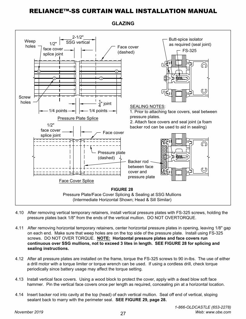
FIGURE 28
Pressure Plate/Face Cover Splicing & Sealing at SSG Mullions
(Intermediate Horizontal Shown; Head & Sill Similar)
2-1/2"
SSG vertical
1/4 points1/4 points
1
4
" joint
1/2"
face cover
splice joint
Face cover
(dashed)
FS-325
Butt-spice isolator
as required (seal joint)
SEALING NOTES:
1. Prior to attaching face covers, seal between
pressure plates.
2. Attach face covers and seal joint (a foam
backer rod can be used to aid in sealing)
Weep
holes
Face cover
Pressure plate
(dashed)
Backer rod
between face
cover and
pressure plate
Pressure Plate Splice
Face Cover Splice
Screw
holes
1/2"
face cover
splice joint
4.10 After removing vertical temporary retainers, install vertical pressure plates with FS-325 screws, holding the
pressure plates back 1/8" from the ends of the vertical mullion. DO NOT OVERTORQUE.
4.11 After removing horizontal temporary retainers, center horizontal pressure plates in opening, leaving 1/8" gap
on each end. Make sure that weep holes are on the top side of the pressure plate. Install using FS-325
screws. DO NOT OVER TORQUE. NOTE: Horizontal pressure plates and face covers run
continuous over SSG mullions, not to exceed 3 lites in length. SEE FIGURE 28 for splicing and
sealing instructions.
RELIANCE™-SS CURTAIN WALL INSTALLATION MANUAL
November 2019
1-866-OLDCASTLE (653-2278) Web: www.obe.com
27
GLAZING
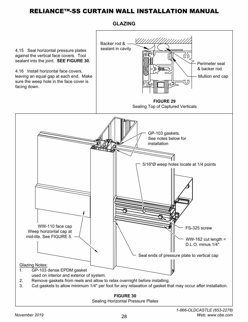
FIGURE 29
Sealing Top of Captured Verticals
Backer rod &
sealant in cavity
Perimeter seal
& backer rod
Mullion end cap
WW-162 cut length =
D.L.O. minus 1/4"
5/16"Ø weep holes locate at 1/4 points
WW-110 face cap
Weep horizontal cap at
mid-lite. See FIGURE 5.
Seal ends of pressure plate to vertical cap
GP-103 gaskets.
See notes below for
installation
FS-325 screw
FIGURE 30
Sealing Horizontal Pressure Plates
Glazing Notes:
1. GP-103 dense EPDM gasket
used on interior and exterior of system.
2. Remove gaskets from reels and allow to relax overnight before installing.
3. Cut gaskets to allow minimum 1/4" per foot for any relaxation of gasket that may occur after installation.
4.15 Seal horizontal pressure plates
against the vertical face covers. Tool
sealant into the joint. SEE FIGURE 30.
4.16 Install horizontal face covers,
leaving an equal gap at each end. Make
sure the weep hole in the face cover is
facing down.
RELIANCE™-SS CURTAIN WALL INSTALLATION MANUAL
November 2019
1-866-OLDCASTLE (653-2278) Web: www.obe.com
28
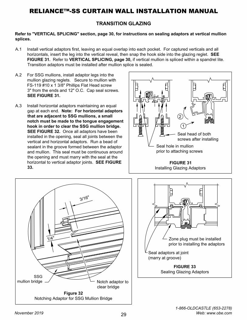
TRANSITION GLAZING
Refer to "VERTICAL SPLICING" section, page 30, for instructions on sealing adaptors at vertical mullion
splices.
A.1 Install vertical adaptors first, leaving an equal overlap into each pocket. For captured verticals and all
horizontals, insert the leg into the vertical reveal, then snap the hook side into the glazing reglet. SEE
FIGURE 31. Refer to VERTICAL SPLICING, page 30, if vertical mullion is spliced within a spandrel lite.
Transition adaptors must be installed after mullion splice is sealed.
A.2 For SSG mullions, install adaptor legs into the
mullion glazing reglets. Secure to mullion with
FS-119 #10 x 1 3/8" Phillips Flat Head screw
3" from the ends and 12" O.C. Cap seal screws.
SEE FIGURE 31.
A.3 Install horizontal adaptors maintaining an equal
gap at each end. Note: For horizontal adaptors
that are adjacent to SSG mullions, a small
notch must be made to the tongue engagement
hook in order to clear the SSG mullion bridge.
SEE FIGURE 32. Once all adaptors have been
installed in the opening, seal all joints between the
vertical and horizontal adaptors. Run a bead of
sealant in the groove formed between the adaptor
and mullion. This seal must be continuous around
the opening and must marry with the seal at the
horizontal to vertical adaptor joints. SEE FIGURE
33.
FIGURE 31
Installing Glazing Adaptors
Seal head of both
screws after installing
Figure 32
Notching Adaptor for SSG Mullion Bridge
3
/1
6
"
1
/4
"
Notch adaptor to
clear bridge
SSG
mullion bridge
FIGURE 33
Sealing Glazing Adaptors
Seal adaptors at joint
(marry at groove)
Zone plug must be installed
prior to installing the adaptors
1
2
Seal hole in mullion
prior to attaching screws
RELIANCE™-SS CURTAIN WALL INSTALLATION MANUAL
November 2019
1-866-OLDCASTLE (653-2278) Web: www.obe.com
29
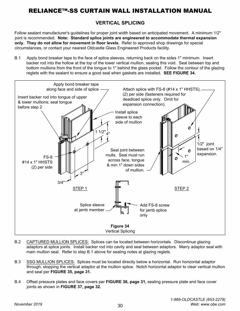
VERTICAL SPLICING
Follow sealant manufacturer's guidelines for proper joint width based on anticipated movement. A minimum 1/2"
joint is recommended. Note: Standard splice joints are engineered to accommodate thermal expansion
only. They do not allow for movement in floor levels. Refer to approved shop drawings for special
circumstances, or contact your nearest Oldcastle Glass Engineered Products facility.
B.1 Apply bond breaker tape to the face of splice sleeves, returning back on the sides 1" minimum. Insert
backer rod into the hollow at the top of the lower vertical mullion, sealing this void. Seal between top and
bottom mullions from the front of the tongue to 1" behind the glass pocket. Follow the contour of the glazing
reglets with the sealant to ensure a good seal when gaskets are installed. SEE FIGURE 34.
Figure 34
Vertical Splicing
4"
1 1/2"
3"
3/4"
Apply bond breaker tape
along face and side of splice
Insert backer rod into tongue of upper
& lower mullions; seal tongue
before step 2
Seal joint between
mulls. Seal must run
across face, tongue
& min 1" down sides
of mullion.
1"
min.
FS-8
#14 x 1" HHSTS
(2) per side
Attach splice with FS-8 (#14 x 1" HHSTS),
(2) per side (fasteners required for
deadload splice only. Omit for
expansion connection).
1/2" joint
based on 1/4"
expansion.
STEP 1
Install splice
sleeve to each
side of mullion
STEP 2
Add FS-8 screw
for jamb splice
only
Splice sleeve
at jamb member
B.2 CAPTURED MULLION SPLICES: Splices can be located between horizontals. Discontinue glazing
adaptors at splice joints. Install backer rod into cavity and seal between adaptors. Marry adaptor seal with
main mullion seal. Refer to step B.1 above for sealing notes at glazing reglets.
B.3 SSG MULLION SPLICES: Splices must be located directly below a horizontal. Run horizontal adaptor
through, stopping the vertical adaptor at the mullion splice. Notch horizontal adaptor to clear vertical mullion
and seal per FIGURE 35, page 31.
B.4 Offset pressure plates and face covers per FIGURE 36, page 31, sealing pressure plate and face cover
joints as shown in FIGURE 37, page 32.
RELIANCE™-SS CURTAIN WALL INSTALLATION MANUAL
November 2019
1-866-OLDCASTLE (653-2278) Web: www.obe.com
30
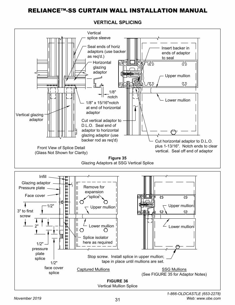
VERTICAL SPLICING
Figure 35
Glazing Adaptors at SSG Vertical Splice
Cut vertical adaptor to
D.L.O. Seal end of
adaptor to horizontal
glazing adaptor (use
backer rod as req'd)
Upper mullion
Lower mullion
Vertical
splice sleeve
1/8" x 15/16"notch
at end of horizontal
adaptor
1/8"
notch
Seal ends of horiz
adaptors (use backer
as req'd.)
Horizontal
glazing
adaptor
Vertical glazing
adaptor
Front View of Splice Detail
(Glass Not Shown for Clarity)
FIGURE 36
Vertical Mullion Splice
Upper mullion
Lower mullion
Glazing adaptor
Pressure plate
Face cover
Infill
Remove for
expansion
splice
Cut horizontal adaptor to D.L.O.
plus 1-13/16". Notch ends to clear
vertical. Seal off end of adaptor
Upper mullion
Lower mullion
1/2"
face cover
splice
2"
3" to first
screw
1/2"
pressure
plate
splice
1/2"
Splice isolator
here as required
Captured Mullions SSG Mullions
(See FIGURE 35 for Adaptor Notes)
Insert backer in
ends of adaptor
to seal
Stop screw. Install splice in upper mullion;
tape in place until mullions are set.
RELIANCE™-SS CURTAIN WALL INSTALLATION MANUAL
November 2019
1-866-OLDCASTLE (653-2278) Web: www.obe.com
31
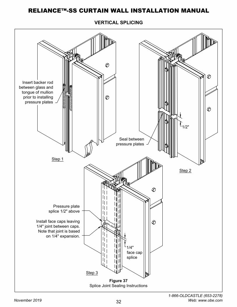
VERTICAL SPLICING
Seal between
pressure plates
1/2"
1/4"
face cap
splice
Insert backer rod
between glass and
tongue of mullion
prior to installing
pressure plates
Step 2
Install face caps leaving
1/4" joint between caps.
Note that joint is based
on 1/4" expansion.
Step 3
Step 1
Pressure plate
splice 1/2" above
Figure 37
Splice Joint Sealing Instructions
RELIANCE™-SS CURTAIN WALL INSTALLATION MANUAL
November 2019
1-866-OLDCASTLE (653-2278) Web: www.obe.com
32
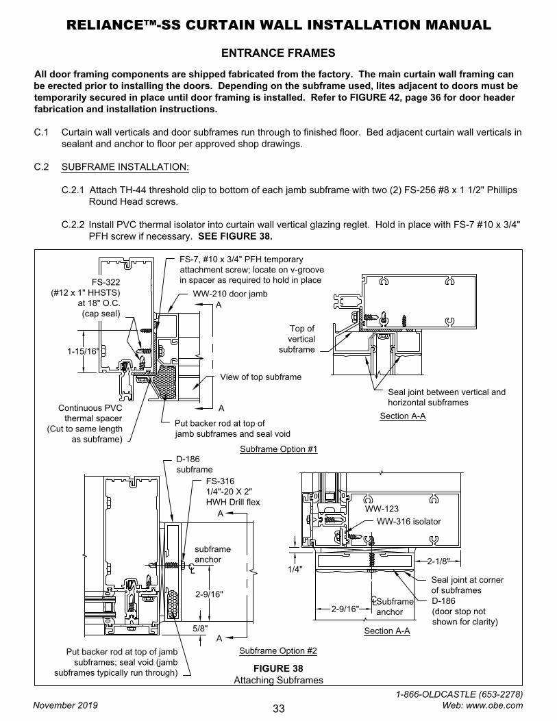
ENTRANCE FRAMES
All door framing components are shipped fabricated from the factory. The main curtain wall framing can
be erected prior to installing the doors. Depending on the subframe used, lites adjacent to doors must be
temporarily secured in place until door framing is installed. Refer to FIGURE 42, page 36 for door header
fabrication and installation instructions.
C.1 Curtain wall verticals and door subframes run through to finished floor. Bed adjacent curtain wall verticals in
sealant and anchor to floor per approved shop drawings.
C.2 SUBFRAME INSTALLATION:
C.2.1 Attach TH-44 threshold clip to bottom of each jamb subframe with two (2) FS-256 #8 x 1 1/2" Phillips
Round Head screws.
C.2.2 Install PVC thermal isolator into curtain wall vertical glazing reglet. Hold in place with FS-7 #10 x 3/4"
PFH screw if necessary. SEE FIGURE 38.
FIGURE 38
Attaching Subframes
WW-210 door jamb
FS-322
(#12 x 1" HHSTS)
at 18" O.C.
(cap seal)
Put backer rod at top of
jamb subframes and seal void
A
A
Seal joint between vertical and
horizontal subframes
Top of
vertical
subframe
View of top subframe
1-15/16"
FS-7, #10 x 3/4" PFH temporary
attachment screw; locate on v-groove
in spacer as required to hold in place
Continuous PVC
thermal spacer
(Cut to same length
as subframe)
A
A
D-186
subframe
2-9/16"
C
L
subframe
anchor
5/8"
FS-316
1/4"-20 X 2"
HWH Drill flex
Put backer rod at top of jamb
subframes; seal void (jamb
subframes typically run through)
Subframe Option #1
Subframe Option #2
WW-123
WW-316 isolator
Seal joint at corner
of subframes
2-9/16"
L
C
Subframe
anchor
2-1/8"
D-186
(door stop not
shown for clarity)
1/4"
Section A-A
Section A-A
RELIANCE™-SS CURTAIN WALL INSTALLATION MANUAL
November 2019
1-866-OLDCASTLE (653-2278) Web: www.obe.com
33
ENTRANCE FRAMES
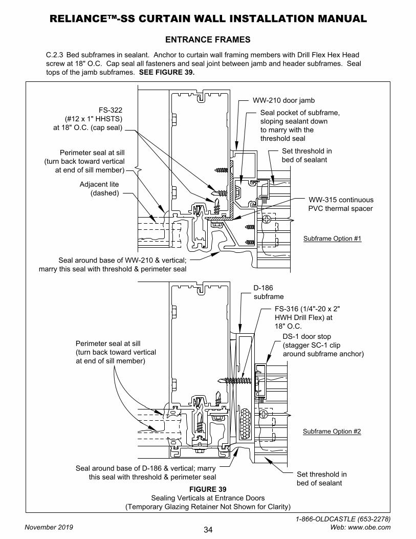
C.2.3 Bed subframes in sealant. Anchor to curtain wall framing members with Drill Flex Hex Head
screw at 18" O.C. Cap seal all fasteners and seal joint between jamb and header subframes. Seal
tops of the jamb subframes. SEE FIGURE 39.
FIGURE 39
Sealing Verticals at Entrance Doors
(Temporary Glazing Retainer Not Shown for Clarity)
WW-210 door jamb
Set threshold in
bed of sealant
Seal pocket of subframe,
sloping sealant down
to marry with the
threshold seal
Perimeter seal at sill
(turn back toward vertical
at end of sill member)
Seal around base of WW-210 & vertical;
marry this seal with threshold & perimeter seal
FS-322
(#12 x 1" HHSTS)
at 18" O.C. (cap seal)
WW-315 continuous
PVC thermal spacer
Adjacent lite
(dashed)
D-186
subframe
Set threshold in
bed of sealant
Perimeter seal at sill
(turn back toward vertical
at end of sill member)
DS-1 door stop
(stagger SC-1 clip
around subframe anchor)
Seal around base of D-186 & vertical; marry
this seal with threshold & perimeter seal
Subframe Option #1
Subframe Option #2
FS-316 (1/4"-20 x 2"
HWH Drill Flex) at
18" O.C.
RELIANCE™-SS CURTAIN WALL INSTALLATION MANUAL
November 2019
1-866-OLDCASTLE (653-2278) Web: www.obe.com
34
ENTRANCE FRAMES
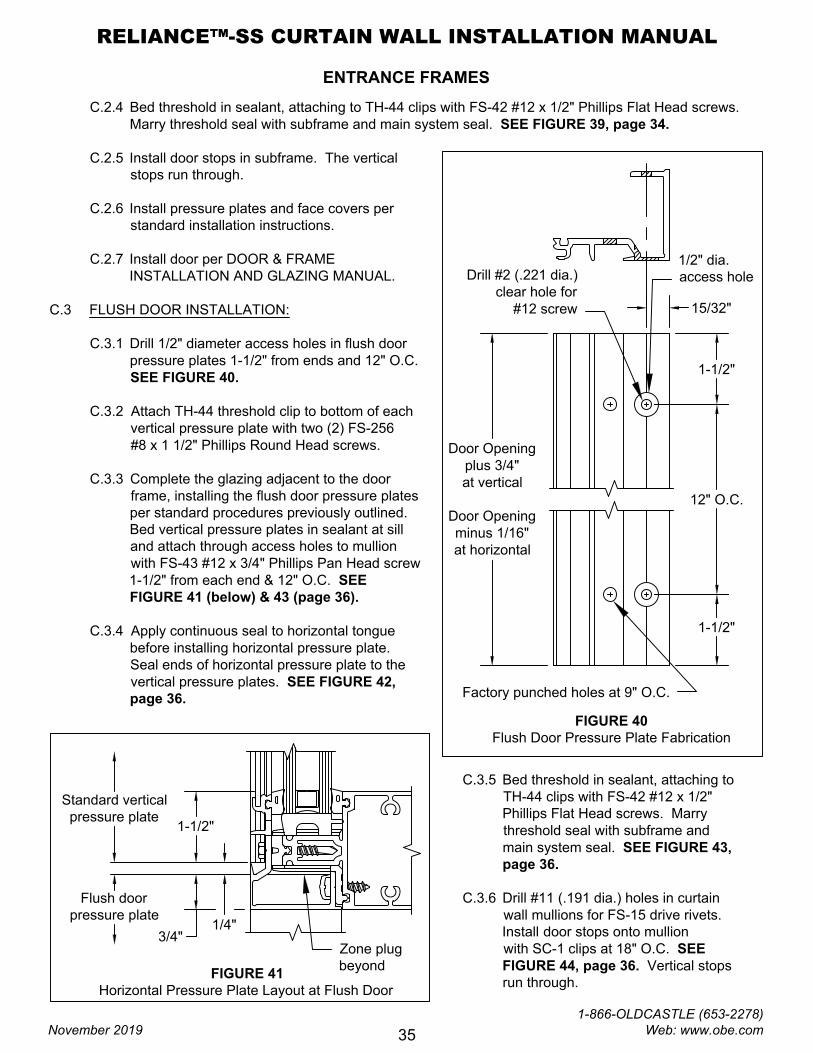
C.2.4 Bed threshold in sealant, attaching to TH-44 clips with FS-42 #12 x 1/2" Phillips Flat Head screws.
Marry threshold seal with subframe and main system seal. SEE FIGURE 39, page 34.
C.2.5 Install door stops in subframe. The vertical
stops run through.
C.2.6 Install pressure plates and face covers per
standard installation instructions.
C.2.7 Install door per DOOR & FRAME
INSTALLATION AND GLAZING MANUAL.
C.3 FLUSH DOOR INSTALLATION:
C.3.1 Drill 1/2" diameter access holes in flush door
pressure plates 1-1/2" from ends and 12" O.C.
SEE FIGURE 40.
C.3.2 Attach TH-44 threshold clip to bottom of each
vertical pressure plate with two (2) FS-256
#8 x 1 1/2" Phillips Round Head screws.
C.3.3 Complete the glazing adjacent to the door
frame, installing the flush door pressure plates
per standard procedures previously outlined.
Bed vertical pressure plates in sealant at sill
and attach through access holes to mullion
with FS-43 #12 x 3/4" Phillips Pan Head screw
1-1/2" from each end & 12" O.C. SEE
FIGURE 41 (below) & 43 (page 36).
C.3.4 Apply continuous seal to horizontal tongue
before installing horizontal pressure plate.
Seal ends of horizontal pressure plate to the
vertical pressure plates. SEE FIGURE 42,
page 36.
FIGURE 40
Flush Door Pressure Plate Fabrication
1-1/2"
1-1/2"
12" O.C.
15/32"
1/2" dia.
access hole
Door Opening
plus 3/4"
at vertical
Door Opening
minus 1/16"
at horizontal
Factory punched holes at 9" O.C.
Drill #2 (.221 dia.)
clear hole for
#12 screw
FIGURE 41
Horizontal Pressure Plate Layout at Flush Door
Zone plug
beyond
1/4"
3/4"
1-1/2"
Standard vertical
pressure plate
Flush door
pressure plate
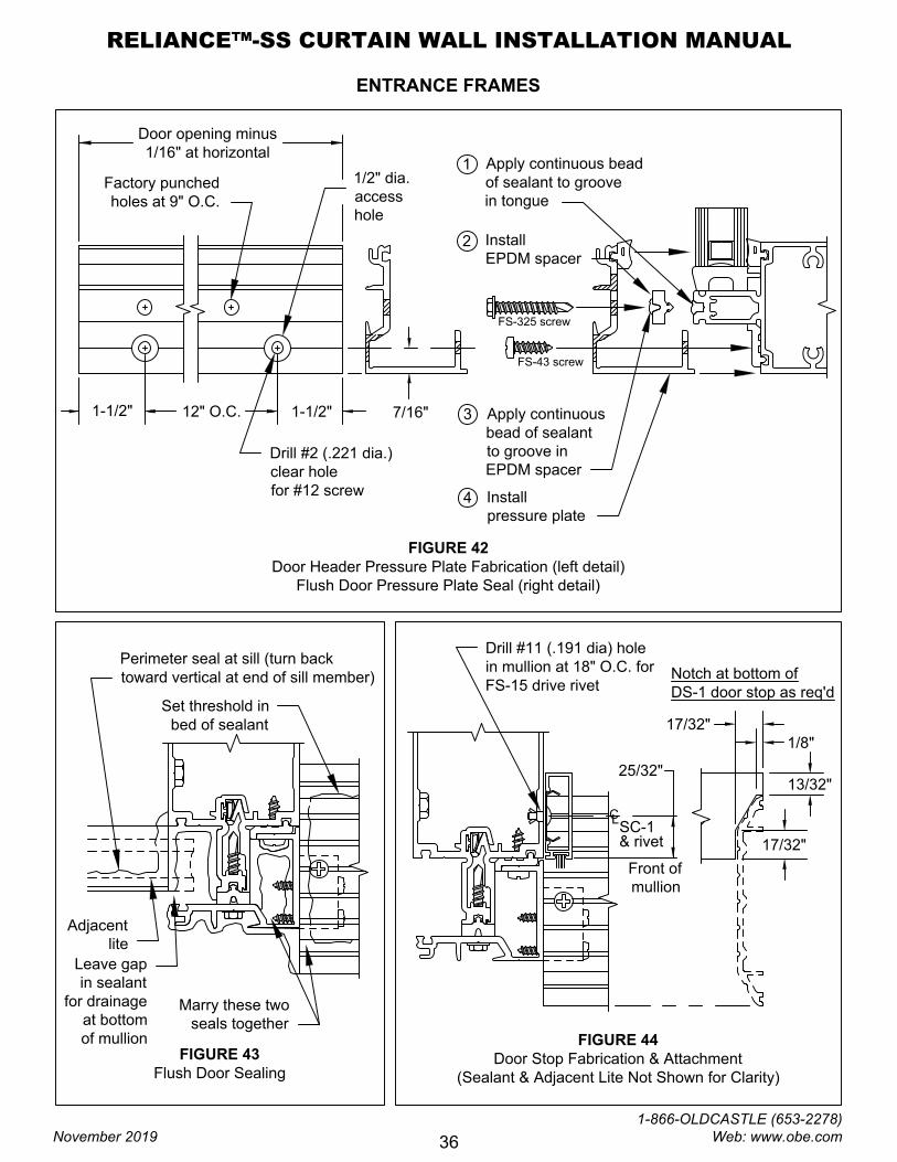
C.3.5 Bed threshold in sealant, attaching to
TH-44 clips with FS-42 #12 x 1/2"
Phillips Flat Head screws. Marry
threshold seal with subframe and
main system seal. SEE FIGURE 43,
page 36.
C.3.6 Drill #11 (.191 dia.) holes in curtain
wall mullions for FS-15 drive rivets.
Install door stops onto mullion
with SC-1 clips at 18" O.C. SEE
FIGURE 44, page 36. Vertical stops
run through.
RELIANCE™-SS CURTAIN WALL INSTALLATION MANUAL
November 2019
1-866-OLDCASTLE (653-2278) Web: www.obe.com
35
ENTRANCE FRAMES
FIGURE 42
Door Header Pressure Plate Fabrication (left detail)
Flush Door Pressure Plate Seal (right detail)
1
FS-325 screw
Apply continuous bead
of sealant to groove
in tongue
Install
EPDM spacer
Install
pressure plate
Apply continuous
bead of sealant
to groove in
EPDM spacer
FS-43 screw
Drill #2 (.221 dia.)
clear hole
for #12 screw
1/2" dia.
access
hole
Factory punched
holes at 9" O.C.
12" O.C.
Door opening minus
1/16" at horizontal
1-1/2"1-1/2"
7/16"
2
3
4
FIGURE 43
Flush Door Sealing
Adjacent
lite
Perimeter seal at sill (turn back
toward vertical at end of sill member)
Set threshold in
bed of sealant
Leave gap
in sealant
for drainage
at bottom
of mullion
Marry these two
seals together
FIGURE 44
Door Stop Fabrication & Attachment
(Sealant & Adjacent Lite Not Shown for Clarity)
C
L
SC-1
& rivet
Drill #11 (.191 dia) hole
in mullion at 18" O.C. for
FS-15 drive rivet
25/32"
1/8"
17/32"
13/32"
17/32"
Notch at bottom of
DS-1 door stop as req'd
Front of
mullion
RELIANCE™-SS CURTAIN WALL INSTALLATION MANUAL
November 2019
1-866-OLDCASTLE (653-2278) Web: www.obe.com
36
ENTRANCE FRAMES
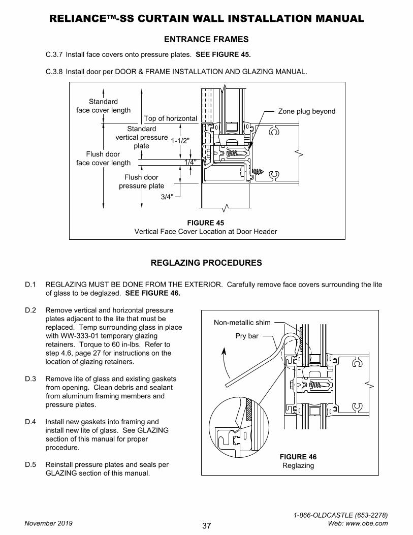
C.3.7 Install face covers onto pressure plates. SEE FIGURE 45.
C.3.8 Install door per DOOR & FRAME INSTALLATION AND GLAZING MANUAL.
FIGURE 45
Vertical Face Cover Location at Door Header
1/4"
3/4"
1-1/2"
Standard
vertical pressure
plate
Flush door
pressure plate
Standard
face cover length
Flush door
face cover length
Top of horizontal
Zone plug beyond
REGLAZING PROCEDURES
D.1 REGLAZING MUST BE DONE FROM THE EXTERIOR. Carefully remove face covers surrounding the lite
of glass to be deglazed. SEE FIGURE 46.
D.2 Remove vertical and horizontal pressure
plates adjacent to the lite that must be
replaced. Temp surrounding glass in place
with WW-333-01 temporary glazing
retainers. Torque to 60 in-lbs. Refer to
step 4.6, page 27 for instructions on the
location of glazing retainers.
D.3 Remove lite of glass and existing gaskets
from opening. Clean debris and sealant
from aluminum framing members and
pressure plates.
D.4 Install new gaskets into framing and
install new lite of glass. See GLAZING
section of this manual for proper
procedure.
D.5 Reinstall pressure plates and seals per
GLAZING section of this manual.
FIGURE 46
Reglazing
Non-metallic shim
Pry bar
RELIANCE™-SS CURTAIN WALL INSTALLATION MANUAL
November 2019
1-866-OLDCASTLE (653-2278) Web: www.obe.com
37
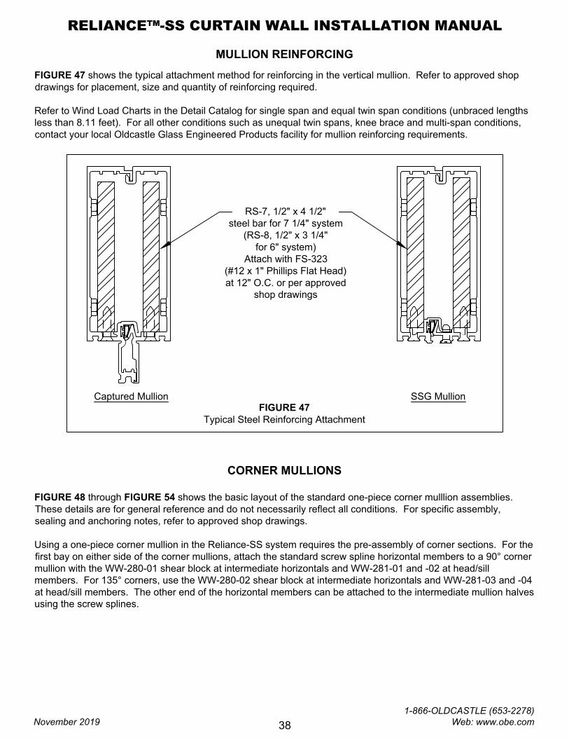
MULLION REINFORCING
FIGURE 47 shows the typical attachment method for reinforcing in the vertical mullion. Refer to approved shop
drawings for placement, size and quantity of reinforcing required.
Refer to Wind Load Charts in the Detail Catalog for single span and equal twin span conditions (unbraced lengths
less than 8.11 feet). For all other conditions such as unequal twin spans, knee brace and multi-span conditions,
contact your local Oldcastle Glass Engineered Products facility for mullion reinforcing requirements.
FIGURE 47
Typical Steel Reinforcing Attachment
Captured Mullion SSG Mullion
RS-7, 1/2" x 4 1/2"
steel bar for 7 1/4" system
(RS-8, 1/2" x 3 1/4"
for 6" system)
Attach with FS-323
(#12 x 1" Phillips Flat Head)
at 12" O.C. or per approved
shop drawings
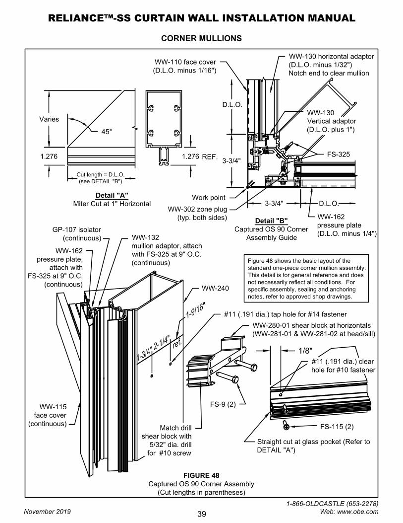
CORNER MULLIONS
FIGURE 48 through FIGURE 54 shows the basic layout of the standard one-piece corner mulllion assemblies.
These details are for general reference and do not necessarily reflect all conditions. For specific assembly,
sealing and anchoring notes, refer to approved shop drawings.
Using a one-piece corner mullion in the Reliance-SS system requires the pre-assembly of corner sections. For the
first bay on either side of the corner mullions, attach the standard screw spline horizontal members to a 90° corner
mullion with the WW-280-01 shear block at intermediate horizontals and WW-281-01 and -02 at head/sill
members. For 135° corners, use the WW-280-02 shear block at intermediate horizontals and WW-281-03 and -04
at head/sill members. The other end of the horizontal members can be attached to the intermediate mullion halves
using the screw splines.
RELIANCE™-SS CURTAIN WALL INSTALLATION MANUAL
November 2019
1-866-OLDCASTLE (653-2278) Web: www.obe.com
38
WW-240
WW-280-01 shear block at horizontals
(WW-281-01 & WW-281-02 at head/sill)
FS-9 (2)
FS-115 (2)
Straight cut at glass pocket (Refer to
DETAIL "A")
1.276
45°
Detail "A"
Miter Cut at 1" Horizontal
WW-115
face cover
(continuous)
WW-162
pressure plate,
attach with
FS-325 at 9" O.C.
(continuous)
GP-107 isolator
(continuous)
WW-132
mullion adaptor, attach
with FS-325 at 9" O.C.
(continuous)
Varies
1.276REF.
Cut length = D.L.O.
(see DETAIL "B")
3-3/4" D.L.O.
Work point
3-3/4"
D.L.O.
WW-130
Vertical adaptor
(D.L.O. plus 1")
WW-130 horizontal adaptor
(D.L.O. minus 1/32")
Notch end to clear mullion
Detail "B"
Captured OS 90 Corner
Assembly Guide
Match drill
shear block with
5/32" dia. drill
for #10 screw
FS-325
WW-302 zone plug
(typ. both sides)
1
-
3
/
4
"
2
-
1
/
4
"
1
-
9
/
1
6
"
r
e
f
.
#11 (.191 dia.) tap hole for #14 fastener
#11 (.191 dia.) clear
hole for #10 fastener
Figure 48 shows the basic layout of the
standard one-piece corner mullion assembly.
This detail is for general reference and does
not necessarily reflect all conditions. For
specific assembly, sealing and anchoring
notes, refer to approved shop drawings.
WW-162
pressure plate
(D.L.O. minus 1/4")
WW-110 face cover
(D.L.O. minus 1/16")
FIGURE 48
Captured OS 90 Corner Assembly
(Cut lengths in parentheses)
1/8"
CORNER MULLIONS
RELIANCE™-SS CURTAIN WALL INSTALLATION MANUAL
November 2019
1-866-OLDCASTLE (653-2278) Web: www.obe.com
39
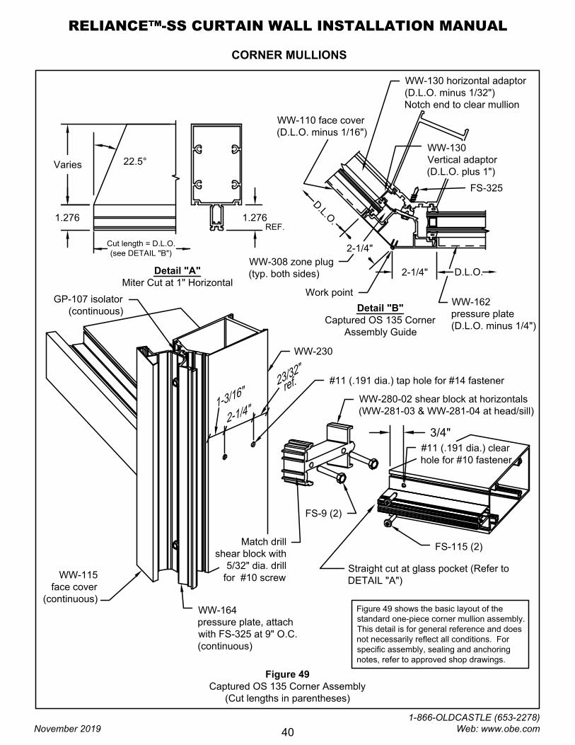
Figure 49
Captured OS 135 Corner Assembly
(Cut lengths in parentheses)
22.5°
WW-164
pressure plate, attach
with FS-325 at 9" O.C.
(continuous)
2-1/4"
D
.
L
.
O
.
WW-308 zone plug
(typ. both sides)
1
-
3
/
1
6
"
2
-
1
/4
"
2
3
/
3
2
"
r
e
f
.
WW-110 face cover
(D.L.O. minus 1/16")
WW-230
WW-280-02 shear block at horizontals
(WW-281-03 & WW-281-04 at head/sill)
FS-9 (2)
FS-115 (2)
Straight cut at glass pocket (Refer to
DETAIL "A")
1.276
Detail "A"
Miter Cut at 1" Horizontal
WW-115
face cover
(continuous)
GP-107 isolator
(continuous)
Varies
1.276
REF.
Cut length = D.L.O.
(see DETAIL "B")
Work point
WW-130
Vertical adaptor
(D.L.O. plus 1")
WW-130 horizontal adaptor
(D.L.O. minus 1/32")
Notch end to clear mullion
Detail "B"
Captured OS 135 Corner
Assembly Guide
Match drill
shear block with
5/32" dia. drill
for #10 screw
FS-325
#11 (.191 dia.) tap hole for #14 fastener
#11 (.191 dia.) clear
hole for #10 fastener
Figure 49 shows the basic layout of the
standard one-piece corner mullion assembly.
This detail is for general reference and does
not necessarily reflect all conditions. For
specific assembly, sealing and anchoring
notes, refer to approved shop drawings.
WW-162
pressure plate
(D.L.O. minus 1/4")
3/4"
2-1/4" D.L.O.
CORNER MULLIONS
RELIANCE™-SS CURTAIN WALL INSTALLATION MANUAL
November 2019
1-866-OLDCASTLE (653-2278) Web: www.obe.com
40
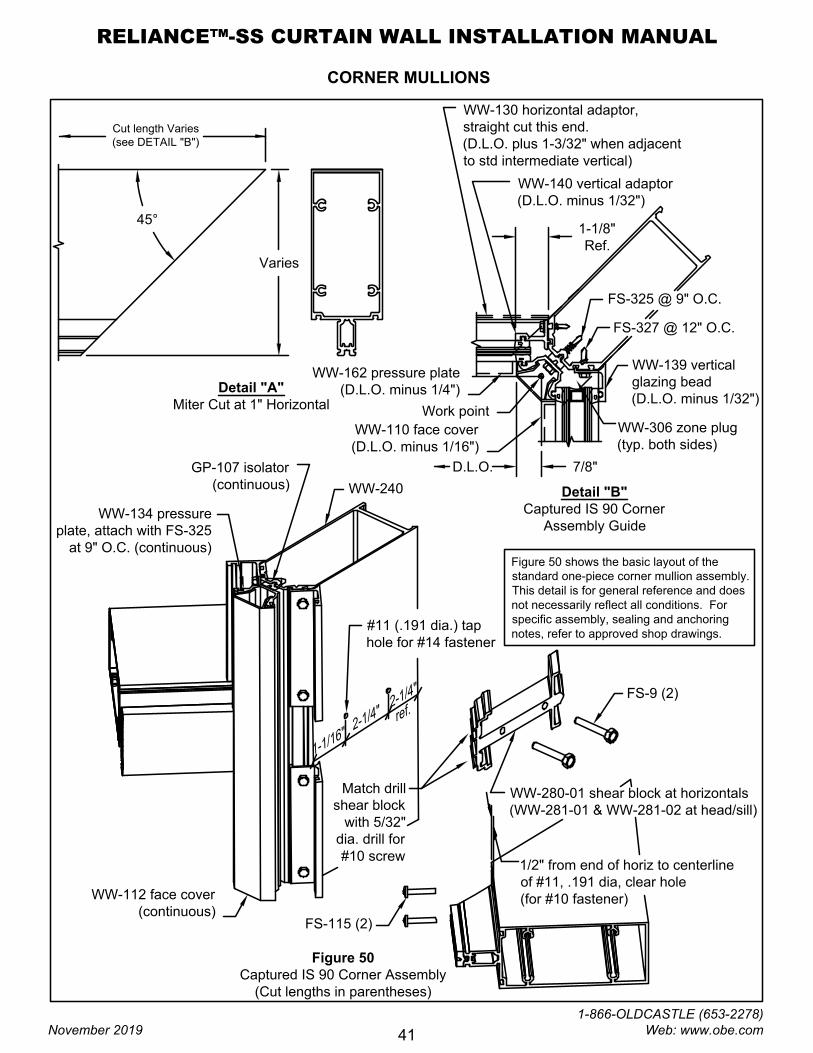
Figure 50
Captured IS 90 Corner Assembly
(Cut lengths in parentheses)
WW-240
WW-280-01 shear block at horizontals
(WW-281-01 & WW-281-02 at head/sill)
FS-9 (2)
FS-115 (2)
WW-112 face cover
(continuous)
WW-134 pressure
plate, attach with FS-325
at 9" O.C. (continuous)
GP-107 isolator
(continuous)
WW-140 vertical adaptor
(D.L.O. minus 1/32")
WW-130 horizontal adaptor,
straight cut this end.
(D.L.O. plus 1-3/32" when adjacent
to std intermediate vertical)
Match drill
shear block
with 5/32"
dia. drill for
#10 screw
1/2" from end of horiz to centerline
of #11, .191 dia, clear hole
(for #10 fastener)
Work point
7/8"D.L.O.
WW-139 vertical
glazing bead
(D.L.O. minus 1/32")
1-1/8"
Ref.
FS-325 @ 9" O.C.
WW-306 zone plug
(typ. both sides)
2
-
1
/
4
"
2
-
1
/
4
"
1
-
1
/
1
6
"
r
e
f
.
#11 (.191 dia.) tap
hole for #14 fastener
FS-327 @ 12" O.C.
Varies
45°
WW-162 pressure plate
(D.L.O. minus 1/4")
WW-110 face cover
(D.L.O. minus 1/16")
Detail "A"
Miter Cut at 1" Horizontal
Cut length Varies
(see DETAIL "B")
Detail "B"
Captured IS 90 Corner
Assembly Guide
Figure 50 shows the basic layout of the
standard one-piece corner mullion assembly.
This detail is for general reference and does
not necessarily reflect all conditions. For
specific assembly, sealing and anchoring
notes, refer to approved shop drawings.
CORNER MULLIONS
RELIANCE™-SS CURTAIN WALL INSTALLATION MANUAL
November 2019
1-866-OLDCASTLE (653-2278) Web: www.obe.com
41
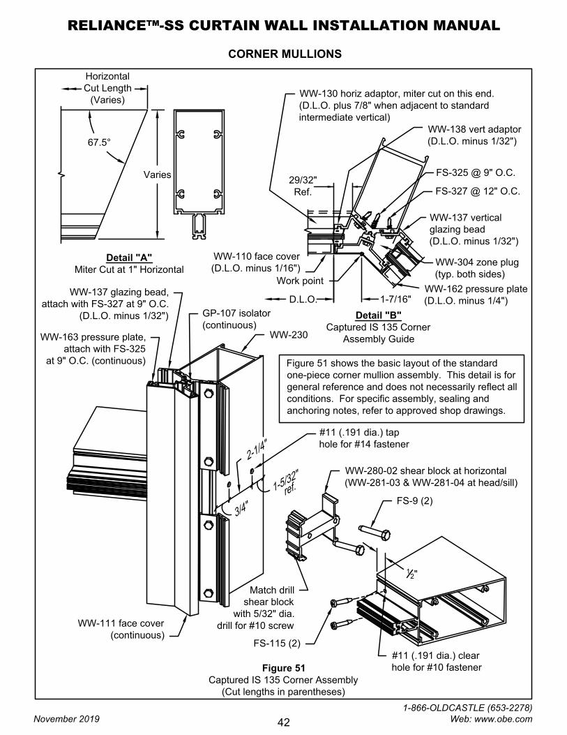
Figure 51
Captured IS 135 Corner Assembly
(Cut lengths in parentheses)
1
2
"
WW-230
WW-280-02 shear block at horizontal
(WW-281-03 & WW-281-04 at head/sill)
FS-9 (2)
FS-115 (2)
WW-111 face cover
(continuous)
WW-163 pressure plate,
attach with FS-325
at 9" O.C. (continuous)
GP-107 isolator
(continuous)
WW-137 glazing bead,
attach with FS-327 at 9" O.C.
(D.L.O. minus 1/32")
WW-138 vert adaptor
(D.L.O. minus 1/32")
WW-130 horiz adaptor, miter cut on this end.
(D.L.O. plus 7/8" when adjacent to standard
intermediate vertical)
Detail "B"
Captured IS 135 Corner
Assembly Guide
Match drill
shear block
with 5/32" dia.
drill for #10 screw
Work point
WW-137 vertical
glazing bead
(D.L.O. minus 1/32")
1-7/16"
29/32"
Ref.
FS-325 @ 9" O.C.
WW-304 zone plug
(typ. both sides)
3
/
4
"
2
-
1
/
4
"
1
-
5
/
3
2
"
r
e
f
.
#11 (.191 dia.) tap
hole for #14 fastener
#11 (.191 dia.) clear
hole for #10 fastener
FS-327 @ 12" O.C.
67.5°
Varies
Detail "A"
Miter Cut at 1" Horizontal
Figure 51 shows the basic layout of the standard
one-piece corner mullion assembly. This detail is for
general reference and does not necessarily reflect all
conditions. For specific assembly, sealing and
anchoring notes, refer to approved shop drawings.
Horizontal
Cut Length
(Varies)
WW-162 pressure plate
(D.L.O. minus 1/4")
WW-110 face cover
(D.L.O. minus 1/16")
D.L.O.
CORNER MULLIONS
RELIANCE™-SS CURTAIN WALL INSTALLATION MANUAL
November 2019
1-866-OLDCASTLE (653-2278) Web: www.obe.com
42
WW-312 zone plug. Seal sides
that contact horizontal and
vertical. Seal face of plug prior
to installing pressure plate.
GP-105 spacer gasket
(D.L.O. plus 1")
Detail "B"
SSG OS 90 Corner
Assembly Guide
Work point
3-3/4"
D.L.O.
WW-136
Vertical adaptor
(D.L.O. minus 1/32")
WW-130
Horizontal adaptor
(D.L.O. plus 3/4")
WW-110 face
(D.L.O. plus 3-3/4")
WW-116 face
(D.L.O. plus 1")
GP-107 isolator
(D.L.O. plus 1")
WW-162
pressure plate
(D.L.O. plus 3-1/4")
GP-107 isolator
(D.L.O. plus 1-1/4"
-stops at zone plug)
WW-169
mullion adaptor
(D.L.O. plus 1")
Detail "A"
Miter Cut at 1" Horizontal
Varies
Cut length =
D.L.O. plus 1-9/32"
(see DETAIL "B")
45°
Vertical face
Vertical mullion adaptor
Horizontal face
(pressure plate
behind not shown
for clarity)
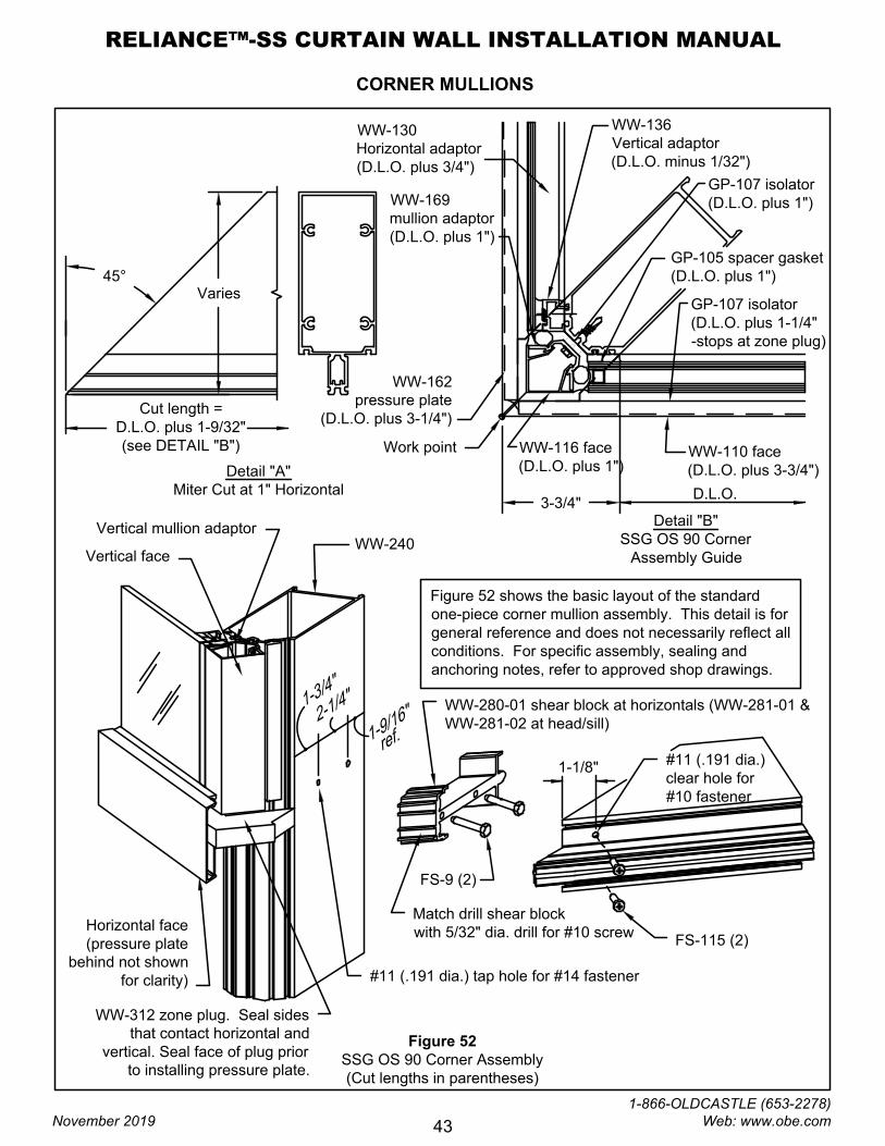
Figure 52
SSG OS 90 Corner Assembly
(Cut lengths in parentheses)
WW-280-01 shear block at horizontals (WW-281-01 &
WW-281-02 at head/sill)
FS-9 (2)
1
-
3
/
4
"
2
-
1
/
4
"
1
-
9
/
1
6
"
r
e
f
.
FS-115 (2)
1-1/8"
#11 (.191 dia.)
clear hole for
#10 fastener
Figure 52 shows the basic layout of the standard
one-piece corner mullion assembly. This detail is for
general reference and does not necessarily reflect all
conditions. For specific assembly, sealing and
anchoring notes, refer to approved shop drawings.
Match drill shear block
with 5/32" dia. drill for #10 screw
WW-240
#11 (.191 dia.) tap hole for #14 fastener
CORNER MULLIONS
RELIANCE™-SS CURTAIN WALL INSTALLATION MANUAL
November 2019
1-866-OLDCASTLE (653-2278) Web: www.obe.com
43
Detail "A"
Miter Cut at 1" Horizontal
Varies
Horizontal cut length
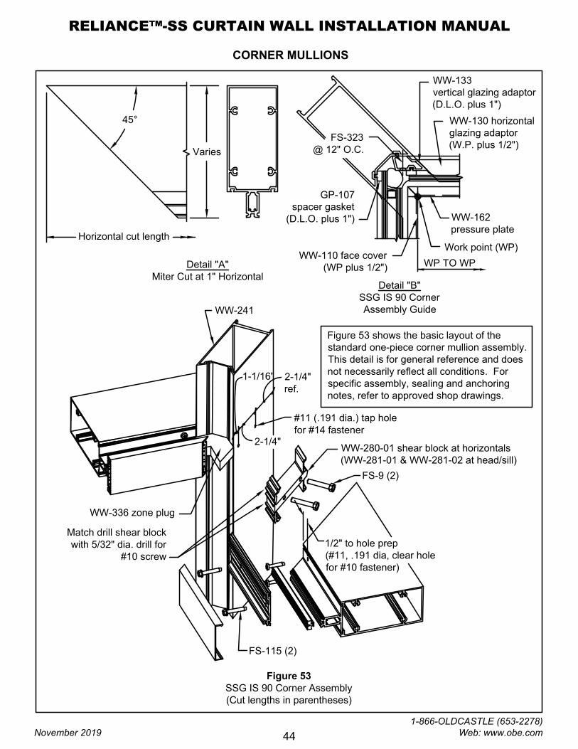
Figure 53
SSG IS 90 Corner Assembly
(Cut lengths in parentheses)
WP TO WP
45°
Detail "B"
SSG IS 90 Corner
Assembly Guide
WW-133
vertical glazing adaptor
(D.L.O. plus 1")
GP-107
spacer gasket
(D.L.O. plus 1")
WW-162
pressure plate
WW-110 face cover
(WP plus 1/2")
Figure 53 shows the basic layout of the
standard one-piece corner mullion assembly.
This detail is for general reference and does
not necessarily reflect all conditions. For
specific assembly, sealing and anchoring
notes, refer to approved shop drawings.
WW-130 horizontal
glazing adaptor
(W.P. plus 1/2")
Work point (WP)
FS-323
@ 12" O.C.
WW-241
WW-280-01 shear block at horizontals
(WW-281-01 & WW-281-02 at head/sill)
FS-9 (2)
FS-115 (2)
Match drill shear block
with 5/32" dia. drill for
#10 screw
1/2" to hole prep
(#11, .191 dia, clear hole
for #10 fastener)
#11 (.191 dia.) tap hole
for #14 fastener
WW-336 zone plug
CORNER MULLIONS
1-1/16"2-1/4"
ref.
2-1/4"
RELIANCE™-SS CURTAIN WALL INSTALLATION MANUAL
November 2019
1-866-OLDCASTLE (653-2278) Web: www.obe.com
44
Varies
67.5°
GP-105 spacer gasket
(D.L.O. plus 1")
WW-135 vertical
glazing adaptor
(D.L.O. plus 1")
Work point
2-3/16"
D.L.O.
WW-114 face cover
(D.L.O. plus 1")
WW-168 mullion adaptor
(D.L.O. plus 1")
2-3/16"
D.L.O.
WW-130 horizontal
glazing adaptor
(D.L.O. minus 1/32")
Cut length =
D.L.O. plus 1/2"
FS-115 (2)
WW-280-02 shear block at horizontals
(WW-281-03 & WW-281-04 at head/sill)
FS-9 (2)
#11 (.191 dia.)
tap hole for
#14 fastener
#11 (.191 dia.)
clear hole for #10 fastener
3
/4
"
1
-
3
/
1
6
"
2
-
1
/
4
"
2
3
/
3
2
"
r
e
f
.
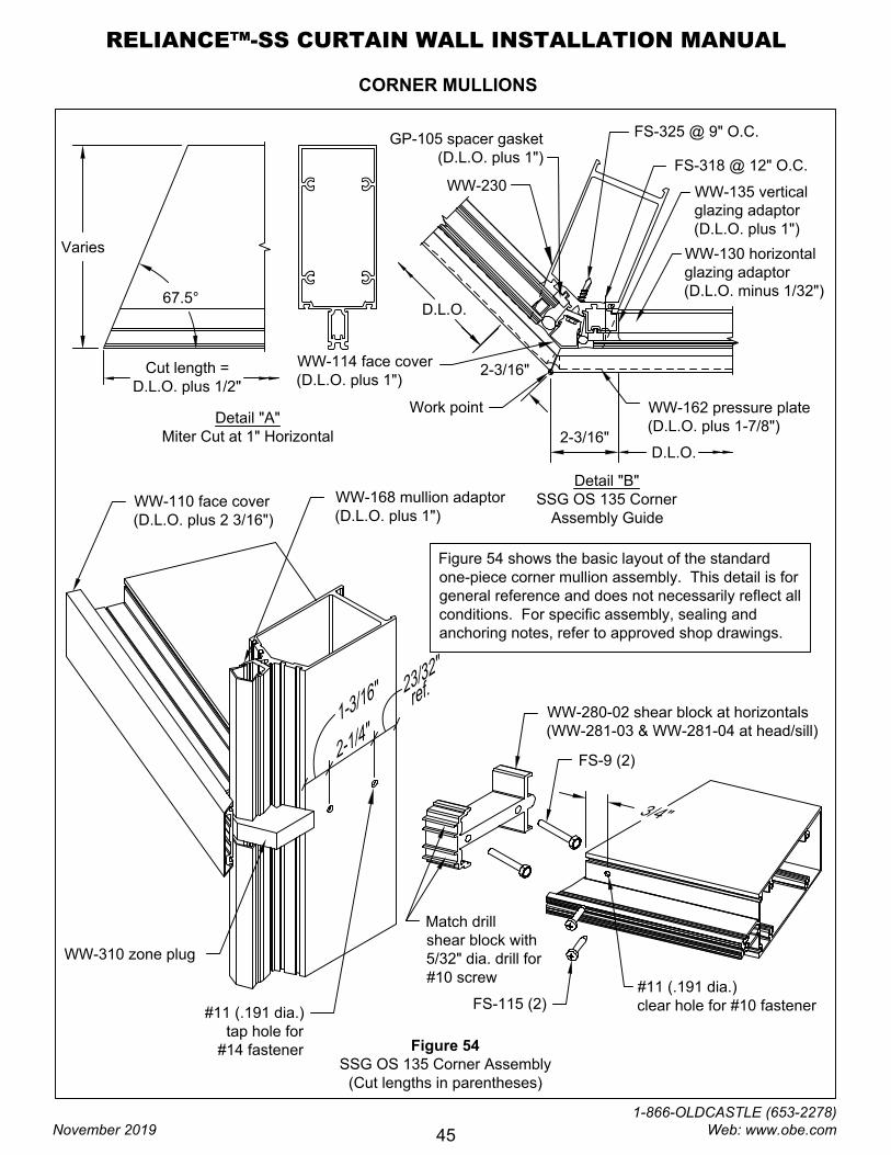
Figure 54 shows the basic layout of the standard
one-piece corner mullion assembly. This detail is for
general reference and does not necessarily reflect all
conditions. For specific assembly, sealing and
anchoring notes, refer to approved shop drawings.
Detail "A"
Miter Cut at 1" Horizontal
Detail "B"
SSG OS 135 Corner
Assembly Guide
WW-162 pressure plate
(D.L.O. plus 1-7/8")
WW-110 face cover
(D.L.O. plus 2 3/16")
FS-325 @ 9" O.C.
Match drill
shear block with
5/32" dia. drill for
#10 screw
FS-318 @ 12" O.C.
WW-310 zone plug
Figure 54
SSG OS 135 Corner Assembly
(Cut lengths in parentheses)
CORNER MULLIONS
WW-230
RELIANCE™-SS CURTAIN WALL INSTALLATION MANUAL
November 2019
1-866-OLDCASTLE (653-2278) Web: www.obe.com
45

PARTS LIST
WW-446
WW-447
WW-448
WW-443
WW-441
WW-444
Head
Sill
Head & Sill Cover
Jamb
Captured Vertical -
Right
SSG Vertical -
Left
4" BACKMEMBERS
6" SYSTEM DEPTH 7 1/4" SYSTEM DEPTH
5 1/4" BACKMEMBERS - cont'd
Captured Vertical -
Left
WW-440
WW-445
SSG Vertical -
Right
135° SSG Outside Corner
Face Cap
7 1/4" & 6"
WW-132
WW-116
WW-115
WW-114
90° Outside Corner
Mullion Adaptor
7 1/4" & 6"
90° SSG Outside Corner
Face Cap
7 1/4" & 6"
90° Outside Corner
Face Cap
7 1/4" & 6" (2 Per Corner)
WW-240
WW-113
WW-112
WW-111
WW-241
WW-230
90°Corner Mullion
OS-Captured & SSG
IS-Captured
7 1/4" & 6"
135° Outside Corner
Face Cap
7 1/4" & 6" (2 Per Corner)
90° Inside Corner
Face Cap
7 1/4" & 6"
135° Inside Corner
Face Cap
7 1/4" & 6"
90° Corner Mullion
IS-SSG
7 1/4" & 6"
135° Corner Mullion
Captured & SSG
7 1/4" & 6"
90° Inside SSG Corner
1/4" Adaptor
7 1/4" & 6"
WW-133
135° Inside Corner
1" Glazing Bead
7 1/4" & 6"
WW-134
90° Inside Corner
Pressure Plate
7 1/4" & 6"
135° SSG Outside Corner
1/4" Adaptor
7 1/4" & 6"
WW-136
WW-137
WW-138
WW-139
WW-140
WW-163
WW-164
WW-135
90° SSG Outside Corner
1/4" Adaptor
7 1/4" & 6"
135° Inside Corner
1/4" Adaptor
7 1/4" & 6"
90° Inside Corner
1" Glazing Bead
7 1/4" & 6"
90° Inside Corner
1/4" Adaptor
7 1/4" & 6"
135° Inside Corner
Pressure Plate
7 1/4" & 6"
135° Outside Corner
Pressure Plate
7 1/4" & 6"
CORNER MULLIONS
WW-442
Horizontal
Captured Vertical -
Right
SSG Vertical -
Left
SSG Vertical -
Right
Horizontal
WW-541
WW-544
WW-545
WW-542
7 1/4" SYSTEM DEPTH
5 1/4" BACKMEMBERS
Head
Sill
Head & Sill Cover
Jamb
Captured Vertical -
Left
WW-546
WW-547
WW-548
WW-543
WW-540
& ACCESSORIES
CORNER MULLIONS
& ACCESSORIES - cont'd
WW-221
WW-220
CW-823
WW-169
WW-168
135° Outside SSG Corner
Pressure Plate
7 1/4" & 6"
90° Outside SSG Corner
Pressure Plate
7 1/4" & 6"
90° Corner Mullion
Snap-In Back Trim
6"
90° Corner Mullion
Snap-In Back Trim
7 1/4"
135° Corner Mullion
Snap-In Back Trim
7 1/4"
RELIANCE™-SS CURTAIN WALL INSTALLATION MANUAL
November 2019
1-866-OLDCASTLE (653-2278) Web: www.obe.com
46
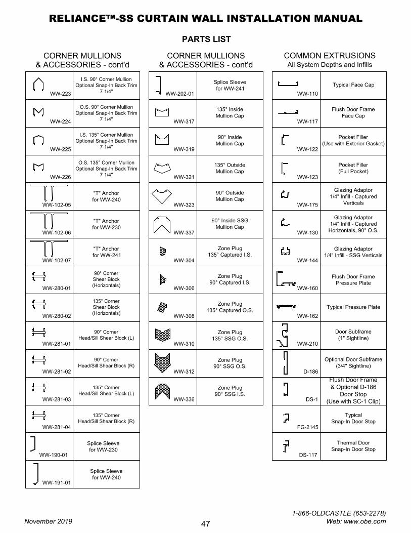
PARTS LIST
90° Corner
Shear Block
(Horizontals)
WW-190-01
WW-280-02
WW-280-01
WW-102-07
WW-102-06
WW-102-05
Splice Sleeve
for WW-230
"T" Anchor
for WW-241
"T" Anchor
for WW-230
"T" Anchor
for WW-240
Splice Sleeve
for WW-241
Splice Sleeve
for WW-240
WW-191-01
WW-202-01
I.S. 90° Corner Mullion
Optional Snap-In Back Trim
7 1/4"
WW-223
WW-224
WW-225
WW-226
90° Inside SSG
Mullion Cap
90° Outside
Mullion Cap
135° Outside
Mullion Cap
WW-337
WW-323
WW-321
90° Inside
Mullion Cap
135° Inside
Mullion Cap
WW-319
WW-317
WW-304
Zone Plug
135° Captured I.S.
WW-306
WW-308
WW-310
WW-312
WW-336
Zone Plug
90° Captured I.S.
Zone Plug
135° SSG O.S.
Zone Plug
135° Captured O.S.
WW-144
WW-130
WW-123
WW-122
WW-117
WW-110
Pocket Filler
(Full Pocket)
Pocket Filler
(Use with Exterior Gasket)
Flush Door Frame
Face Cap
Typical Face Cap
WW-210
WW-162
WW-160
Door Subframe
(1" Sightline)
Typical Pressure Plate
Flush Door Frame
Pressure Plate
Optional Door Subframe
(3/4" Sightline)
D-186
Flush Door Frame
& Optional D-186
Door Stop
(Use with SC-1 Clip)
DS-1
DS-117
FG-2145
Typical
Snap-In Door Stop
CORNER MULLIONS
& ACCESSORIES - cont'd
90° Corner
Head/Sill Shear Block (L)
WW-281-01
WW-281-02
WW-281-03
WW-281-04
CORNER MULLIONS
& ACCESSORIES - cont'dAll System Depths and Infills
COMMON EXTRUSIONS
WW-175
Glazing Adaptor
1/4" Infill - Captured
Verticals
O.S. 90° Corner Mullion
Optional Snap-In Back Trim
7 1/4"
I.S. 135° Corner Mullion
Optional Snap-In Back Trim
7 1/4"
O.S. 135° Corner Mullion
Optional Snap-In Back Trim
7 1/4"
135° Corner
Shear Block
(Horizontals)
90° Corner
Head/Sill Shear Block (R)
135° Corner
Head/Sill Shear Block (L)
135° Corner
Head/Sill Shear Block (R)
Zone Plug
90° SSG O.S.
Zone Plug
90° SSG I.S.
Glazing Adaptor
1/4" Infill - Captured
Horizontals, 90° O.S.
Glazing Adaptor
1/4" Infill - SSG Verticals
Thermal Door
Snap-In Door Stop
RELIANCE™-SS CURTAIN WALL INSTALLATION MANUAL
November 2019
1-866-OLDCASTLE (653-2278) Web: www.obe.com
47
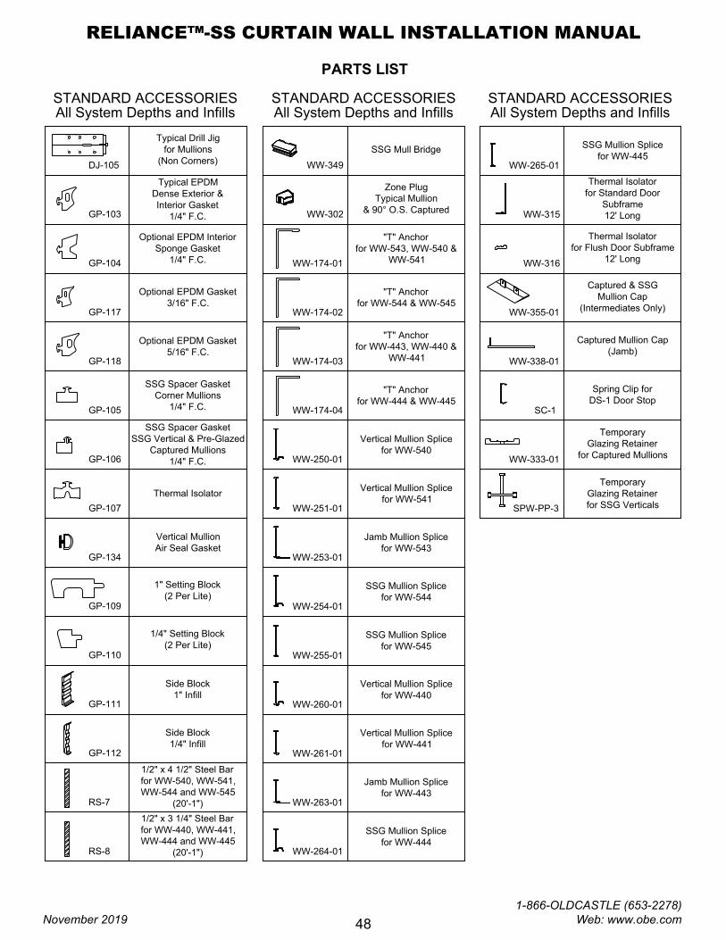
PARTS LIST
GP-105
GP-104
SSG Spacer Gasket
Corner Mullions
1/4" F.C.
Optional EPDM Interior
Sponge Gasket
1/4" F.C.
Thermal Isolator
SSG Spacer Gasket
SSG Vertical & Pre-Glazed
Captured Mullions
1/4" F.C.
GP-106
GP-107
RS-8
RS-7
1/2" x 3 1/4" Steel Bar
for WW-440, WW-441,
WW-444 and WW-445
(20'-1")
1/2" x 4 1/2" Steel Bar
for WW-540, WW-541,
WW-544 and WW-545
(20'-1")
GP-112
GP-111
Side Block
1/4" Infill
Side Block
1" Infill
WW-174-04
WW-174-03
STANDARD ACCESSORIES
All System Depths and Infills
"T" Anchor
for WW-544 & WW-545
Zone Plug
Typical Mullion
& 90° O.S. Captured
"T" Anchor
for WW-543, WW-540 &
WW-541
WW-174-02
WW-174-01
WW-302
SSG Mull Bridge
WW-349
Thermal Isolator
for Flush Door Subframe
12' Long
Thermal Isolator
for Standard Door
Subframe
12' Long
WW-316
WW-315
Vertical Mullion Splice
for WW-541
Vertical Mullion Splice
for WW-540
WW-250-01
WW-251-01
GP-110
GP-109
1/4" Setting Block
(2 Per Lite)
1" Setting Block
(2 Per Lite)
GP-117
Optional EPDM Gasket
3/16" F.C.
GP-118
Temporary
Glazing Retainer
for SSG Verticals
Temporary
Glazing Retainer
for Captured Mullions
SPW-PP-3
WW-333-01
Captured Mullion Cap
(Jamb)
WW-338-01
Spring Clip for
DS-1 Door Stop
SC-1
STANDARD ACCESSORIES
All System Depths and Infills
STANDARD ACCESSORIES
All System Depths and Infills
Vertical Mullion
Air Seal Gasket
GP-134
"T" Anchor
for WW-443, WW-440 &
WW-441
"T" Anchor
for WW-444 & WW-445
Captured & SSG
Mullion Cap
(Intermediates Only)
WW-355-01
Jamb Mullion Splice
for WW-543
SSG Mullion Splice
for WW-544
SSG Mullion Splice
for WW-545
WW-253-01
WW-254-01
WW-255-01
WW-260-01
WW-261-01
WW-263-01
WW-264-01
WW-265-01
Vertical Mullion Splice
for WW-441
Vertical Mullion Splice
for WW-440
Jamb Mullion Splice
for WW-443
SSG Mullion Splice
for WW-444
SSG Mullion Splice
for WW-445
Optional EPDM Gasket
5/16" F.C.
GP-103
DJ-105
Typical EPDM
Dense Exterior &
Interior Gasket
1/4" F.C.
Typical Drill Jig
for Mullions
(Non Corners)
RELIANCE-SS CURTAIN WALL DJ-105
B
A
B
A
C
C
RELIANCE™-SS CURTAIN WALL INSTALLATION MANUAL
November 2019
1-866-OLDCASTLE (653-2278) Web: www.obe.com
48
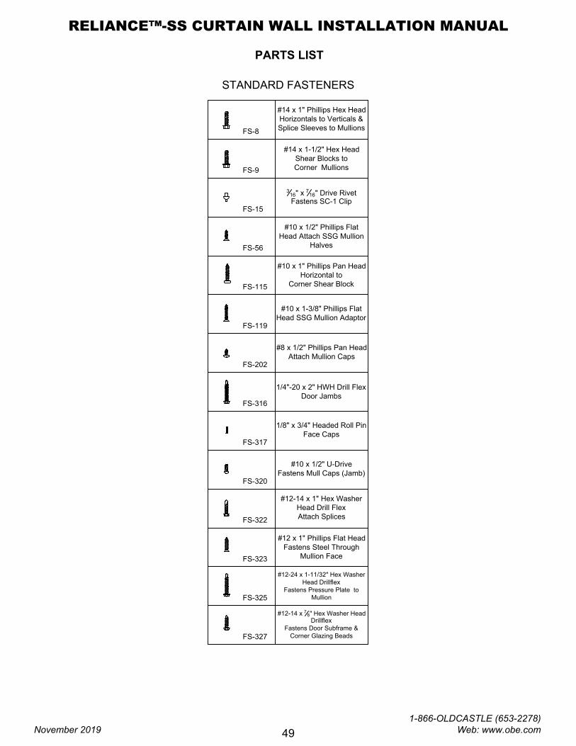
PARTS LIST
#12 x 1" Phillips Flat Head
Fastens Steel Through
Mullion Face
FS-323
FS-325
FS-327
#12-14 x
7
8
" Hex Washer Head
Drillflex
Fastens Door Subframe &
Corner Glazing Beads
#12-24 x 1-11/32" Hex Washer
Head Drillflex
Fastens Pressure Plate to
Mullion
#10 x 1/2" U-Drive
Fastens Mull Caps (Jamb)
FS-320
3
16
" x
7
16
" Drive Rivet
Fastens SC-1 Clip
FS-15
#14 x 1" Phillips Hex Head
Horizontals to Verticals &
Splice Sleeves to Mullions
FS-8
STANDARD FASTENERS
#10 x 1/2" Phillips Flat
Head Attach SSG Mullion
Halves
FS-56
#10 x 1-3/8" Phillips Flat
Head SSG Mullion Adaptor
FS-119
FS-202
FS-322
#8 x 1/2" Phillips Pan Head
Attach Mullion Caps
#12-14 x 1" Hex Washer
Head Drill Flex
Attach Splices
#14 x 1-1/2" Hex Head
Shear Blocks to
Corner Mullions
FS-9
#10 x 1" Phillips Pan Head
Horizontal to
Corner Shear Block
FS-115
1/8" x 3/4" Headed Roll Pin
Face Caps
FS-317
1/4"-20 x 2" HWH Drill Flex
Door Jambs
FS-316
RELIANCE™-SS CURTAIN WALL INSTALLATION MANUAL
November 2019
1-866-OLDCASTLE (653-2278) Web: www.obe.com
49