remote access architecture:1 - upnp
TRANSCRIPT
Remote Access Architecture:1 For UPnP™ Version 1.0 Status: Standardized DCP Date: September 30, 2009 Document Version: 1.0 Service Template Version: 2.00
This Standardized DCP has been adopted as a Standardized DCP by the Steering Committee of the UPnP™ Forum, pursuant to Section 2.1(c)(ii) of the UPnP™ Forum Membership Agreement. UPnP™ Forum Members have rights and licenses defined by Section 3 of the UPnP™ Forum Membership Agreement to use and reproduce the Standardized DCP in UPnP™ Compliant Devices. All such use is subject to all of the provisions of the UPnP™ Forum Membership Agreement.
THE UPNP™ FORUM TAKES NO POSITION AS TO WHETHER ANY INTELLECTUAL PROPERTY RIGHTS EXIST IN THE STANDARDIZED DCPS. THE STANDARDIZED DCPS ARE PROVIDED "AS IS" AND "WITH ALL FAULTS". THE UPNP™ FORUM MAKES NO WARRANTIES, EXPRESS, IMPLIED, STATUTORY, OR OTHERWISE WITH RESPECT TO THE STANDARDIZED DCPS, INCLUDING BUT NOT LIMITED TO ALL IMPLIED WARRANTIES OF MERCHANTABILITY, NON-INFRINGEMENT AND FITNESS FOR A PARTICULAR PURPOSE, OF REASONABLE CARE OR WORKMANLIKE EFFORT, OR RESULTS OR OF LACK OF NEGLIGENCE. Copyright © 2009 UPnPTM Forum. All rights Reserved. Authors Company
Bill Russell Canon
Tom Lawrence Canon
Bich Nguyen (Co-chair) Cisco
Mark Baugher Cisco
Sridhar Ramaswamy Cisco
Ayodele Damola Ericsson
Bryan Roe Intel
Gunner Danneels Intel
Ally (Yu-kyoung) Song LGE
Alexander Kokhanyuk Motorola
Architecture:1 – Document Version 1.0 2
Copyright © 2009 UPnPTM Forum. All rights Reserved.
Authors Company
Jim Morikuni Motorola
Vlad Stirbu Nokia
Cathy Chan Nokia
Jan Brands NXP
Marco Kuystermans NXP
Daniel Meirsman Philips
Suresh Gangadharan Philips
Jeffrey Kang Philips
Wouter van der Beek Philips
Shrikant Kanaparti Samsung
Se-Hee Han Samsung
Mahfuzur Rahman (Co-chair) Samsung
Sanjeev Verma Samsung
Sander Smith Sericon Technology
Bruce Fairman Sony
Jack Manbeck Texas Instruments
Rami Kohanim Universal Devices UPnP Forum in no way guarantees the accuracy or completeness of this author list and in no way implies any rights for or support from those members listed. This list is not the specifications’ contributor list that is kept on the UPnP Forum’s website.
Architecture:1 – Document Version 1.0 3
Copyright © 2009 UPnPTM Forum. All rights Reserved.
Contents Contents..........................................................................................................................................................3 List of Tables..................................................................................................................................................5 List of Figures ................................................................................................................................................6 1 Overview and Scope...............................................................................................................................7
1.1 Notation.............................................................................................................................................7 1.2 References.........................................................................................................................................8
1.2.1 Informative References ..............................................................................................................8 1.3 Terms and Abbreviations ..................................................................................................................9
1.3.1 Abbreviations.............................................................................................................................9 1.3.2 Terms .......................................................................................................................................10
2 Introduction ..........................................................................................................................................12 3 Operational Considerations ................................................................................................................13
3.1 Remote Access Environment ..........................................................................................................13 3.2 Access Networks.............................................................................................................................13
3.2.1 IPv4 Addressing and NAT issues ............................................................................................14 3.2.2 IPv6 Addressing.......................................................................................................................15
3.3 Home Network Environment ..........................................................................................................15 3.3.1 IPv4 Support in Home Routers ................................................................................................15 3.3.2 IPv6 Support in Home Routers ................................................................................................15
3.4 Support Services in the Public Network .........................................................................................15 3.4.1 Server Name Resolution ..........................................................................................................15 3.4.2 Detecting NAT and NAT Type on Server Side .......................................................................16
4 Remote Access Reference Architecture..............................................................................................17 4.1 Remote Access Architecture Paradigm...........................................................................................17 4.2 Remote Access Components Overview ..........................................................................................17 4.3 Remote Access Phases Overview ...................................................................................................19
4.3.1 Setup Services..........................................................................................................................19 4.3.2 Operational Services ................................................................................................................19 4.3.3 Management Service................................................................................................................19
4.4 Remote Access Functionalities .......................................................................................................20 4.4.1 Inbound Connection Configuration .........................................................................................20 4.4.2 Remote Access Discovery Agent.............................................................................................21 4.4.3 Remote Access Transport Agent..............................................................................................22
5 Interaction Model.................................................................................................................................24 5.1 UPnP RA Setup...............................................................................................................................24 5.2 Configure the RAC for Remote Access to Home Network ............................................................24 5.3 Access Home Network Remotely from RAC over the Internet ......................................................25 5.4 UPnP RA Connection Use ..............................................................................................................25 5.5 RADA Synchronization Process .....................................................................................................26 5.6 RADA Heartbeat.............................................................................................................................27
Architecture:1 – Document Version 1.0 4
Copyright © 2009 UPnPTM Forum. All rights Reserved.
5.7 RADA Communication Time-out ...................................................................................................27 5.8 RADA Administrative Shutdown ...................................................................................................27
Appendix A. Deployment Scenarios .....................................................................................................29 A.1 Intended Deployment Scenarios .....................................................................................................30
A.1.1 Remote Access Server in Residential Gateway .......................................................................30 A.1.2 Remote Access Server in a 3rd Party Device...........................................................................30 A.1.3 Remote Access Server Hosted by a 3rd Party in the Internet ..................................................30
Architecture:1 – Document Version 1.0 5
Copyright © 2009 UPnPTM Forum. All rights Reserved.
List of Tables Table 1-1: Abbreviations......................................................................................................................9
Architecture:1 – Document Version 1.0 6
Copyright © 2009 UPnPTM Forum. All rights Reserved.
List of Figures Figure 2-1: UPnP Remote Access. ......................................................................................................12 Figure 3-1: Remote Access Environment. ...........................................................................................13 Figure 3-2: Access Networks. .............................................................................................................14 Figure 4-1: Remote Access Architecture Paradigm.............................................................................17 Figure 4-2: Remote Access Components Overview............................................................................18 Figure 4-3: Typical STUN Configuration in Home Networks ............................................................21 Figure 4-4: Discovery Information Aggregation .................................................................................21 Figure 4-5: Discovery Synchronization...............................................................................................22 Figure 5-1: Remote Access Setup........................................................................................................24 Figure 5-2: Configure the RAC for Remote Access to Home Network ..............................................25 Figure 5-3: Access Home Network Remotely from RAC over the Internet........................................25 Figure 5-4: UPnP RA Connection Use................................................................................................26 Figure 5-5: RADA Synchronization Process.......................................................................................26 Figure 5-6: RADA Heartbeat ..............................................................................................................27 Figure 5-7: RADA Communication Time-out.....................................................................................27 Figure 5-8: RADA Administrative Shutdown.....................................................................................28
Architecture:1 – Document Version 1.0 7
Copyright © 2009 UPnPTM Forum. All rights Reserved.
1 Overview and Scope This document describes an architecture that provides the infrastructure that allows generic UPnP devices, services and control points deployed in remote physical devices to interact with the corresponding UPnP devices, services and control points physically attached to the home network. The mechanisms defined in this architecture will allow to extend the home network so that it will logically include the remote devices so that all devices will be able to communicate among themselves using the UPnP Forum defined mechanisms, e.g. UDA. The desired behavior of the interactions between the remote device and home devices is envisioned to be similar with the one expected as if all devices are located in the same local area network.
In order to accommodate the above mentioned goals, the Remote Access Architecture will provide means to connect the two segments of the extended home network using established mechanisms. The architecture recognizes that there might be several possible alternative models to “bridge” the two segments and will provide an interface that will allow them to be plugged, while enforcing the same overall behavior of the whole system regardless of the model used.
The architecture does not describes any interfaces to “service” gateways that will enable non-UPnP entities to interact with the UPnP devices, services and control points physically attached to the home network.
1.1 Notation • In this document, features are described as Required, Recommended, or Optional as follows:
The key words “MUST,” “MUST NOT,” “REQUIRED,” “SHALL,” “SHALL NOT,” “SHOULD,” “SHOULD NOT,” “RECOMMENDED,” “MAY,” and “OPTIONAL” in this specification are to be interpreted as described in [RFC 2119].
In addition, the following keywords are used in this specification:
PROHIBITED – The definition or behavior is an absolute prohibition of this specification. Opposite of REQUIRED.
CONDITIONALLY REQUIRED – The definition or behavior depends on a condition. If the specified condition is met, then the definition or behavior is REQUIRED, otherwise it is PROHIBITED.
CONDITIONALLY OPTIONAL – The definition or behavior depends on a condition. If the specified condition is met, then the definition or behavior is OPTIONAL, otherwise it is PROHIBITED.
These keywords are thus capitalized when used to unambiguously specify requirements over protocol and application features and behavior that affect the interoperability and security of implementations. When these words are not capitalized, they are meant in their natural-language sense.
• Strings that are to be taken literally are enclosed in “double quotes”.
• Words that are emphasized are printed in italic.
• Keywords that are defined by the UPnP Working Committee are printed using the forum character style.
• Keywords that are defined by the UPnP Device Architecture are printed using the arch character style.
• A double colon delimiter, “::”, signifies a hierarchical parent-child (parent::child) relationship between the two objects separated by the double colon. This delimiter is used in multiple contexts, for example: Service::Action(), Action()::Argument, parentProperty::childProperty.

Architecture:1 – Document Version 1.0 8
Copyright © 2009 UPnPTM Forum. All rights Reserved.
1.2 References
1.2.1 Informative References This section lists the informative references that are provided as information in helping understand this specification:
[DEVICE] – UPnP Device Architecture, version 1.0. Available at: http://www.upnp.org/specs/arch/UPnP-arch-DeviceArchitecture-v1.0-20080424.pdf. Latest version available at: http://www.upnp.org/specs/arch/UPnP-arch-DeviceArchitecture-v1.0.pdf.
[DEVICE-IPv6] – UPnP Device Architecture, version 1.0., Annex A – IP Version 6 Support. Available at: http://www.upnp.org/resources/documents/AnnexA-IPv6_000.pdf
[ICC] – InboundConnectionConfig:1, UPnP Forum, Available at: http://www.upnp.org/specs/ra/UPnP-ra-InboundConnectionConfig-v1-Service-20090930.pdf. Latest version available at: http://www.upnp.org/specs/ra/UPnP-ra-InboundConnectionConfig-v1-Service.pdf.
[RAClient] – RAClient:1, UPnP Forum, Available at: http://www.upnp.org/specs/ra/UPnP-ra-RAClient-v1-Device-20090930.pdf. Latest version available at: http://www.upnp.org/specs/ra/UPnP-ra-RAClient-v1-Device.pdf.
[RADAConfig] – RADAConfig:1, UPnP Forum, Available at: http://www.upnp.org/specs/ra/UPnP-ra-RADAConfig-v1-Service-20090930.pdf. Latest version available at: http://www.upnp.org/specs/ra/UPnP-ra-RADAConfig-v1-Service.pdf.
[RADASync] – RADASync:1, UPnP Forum, Available at: http://www.upnp.org/specs/ra/UPnP-ra-RADASync-v1-Service-20090930.pdf. Latest version available at: http://www.upnp.org/specs/ra/UPnP-ra-RADASync-v1-Service.pdf.
[RADiscoveryAgent] – RADiscoveryAgent:1, UPnP Forum, Available at: http://www.upnp.org/specs/ra/UPnP-ra-RADiscoveryAgent-v1-Device-20090930.pdf. Latest version available at: http://www.upnp.org/specs/ra/UPnP-ra-RADiscoveryAgent-v1-Device.pdf.
[RAServer] – RAServer:1, UPnP Forum, Available at: http://www.upnp.org/specs/ra/UPnP-ra-RAServer-v1-Device-20090930.pdf. Latest version available at: http://www.upnp.org/specs/ra/UPnP-ra-RAServer-v1-Device.pdf.
[RATAConfig] – RATAConfig:1, UPnP Forum, Available at: http://www.upnp.org/specs/ra/UPnP-ra-RATAConfig-v1-Service-20090930.pdf. Latest version available at: http://www.upnp.org/specs/ra/UPnP-ra-RATAConfig-v1-Service.pdf.
[IGD] – InternetGatewayDevice:1, UPnP Forum, November, 2001 Available at: http://www.upnp.org/standardizeddcps/documents/UPnP_IGD_1.0.zip.
[RFC 1889] – IETF RFC 1889, RTP: A Transport Protocol for Real-Time Applications, H. Schulzrinne, S. Casner, R. Frederick, V. Jacobson, January 1996. Available at: http://www.ietf.org/rfc/rfc1889.txt.
[RFC 1918] – IETF RFC 1918, Address Allocation for Private Internets, Y. Rekhter, et. Al, February 1996 Available at: http://www.ietf.org/rfc/rfc1918.txt
[RFC 2119] – IETF RFC 2119, Key words for use in RFCs to Indicate Requirement Levels, S. Bradner, March 1997. Available at: http://www.ietf.org/rfcs/rfc2119.txt.
[RFC 2131] – IETF RFC 2131, Dynamic Host Configuration Protocol, R. Droms, March 1997 Available at: http://www.ietf.org/rfc/rfc2131.txt
Architecture:1 – Document Version 1.0 9
Copyright © 2009 UPnPTM Forum. All rights Reserved.
[RFC 2516] – IETF RFC 2516, A Method for Transmitting PPP Over Ethernet (PPPoE), L. Mamakos, et. Al, February 1999 Available at: http://www.ietf.org/rfc/rfc2516.txt
[RFC 3056] – IETF RFC 3056, Connection of IPv6 Domains via IPv4 Clouds, B. Carpenter, K. Moore, February 2001 Available at: http://www.ietf.org/rfc/rfc3056.txt
[RFC 3489] – IETF RFC 3489, STUN - Simple Traversal of User Datagram Protocol (UDP) Through Network Address Translators (NATs), J. Rosenberg, et. Al, March 2003 Available at: http://www.ietf.org/rfc/rfc3489.txt
[RFC 3550] – IETF RFC 3550, RTP: A Transport Protocol for Real-Time Applications, H. Shulzrinne, et. Al, July 2003 Available at: http://www.ietf.org/rfc/rfc3550.txt
[RFC 4380] – IETF RFC 4380, Teredo: Tunneling IPv6 over UDP through Network Address Translations (NATs), C. Huitema, February 2006 Available at: http://www.ietf.org/rfc/rfc4380.txt
[RFC 3986] – IETF RFC 3986, Uniform Resource Identifier (URI): Generic Syntax, Tim Berners-Lee, et. Al, January 2005. Available at: http://www.ietf.org/rfc/rfc3986.txt
1.3 Terms and Abbreviations
1.3.1 Abbreviations
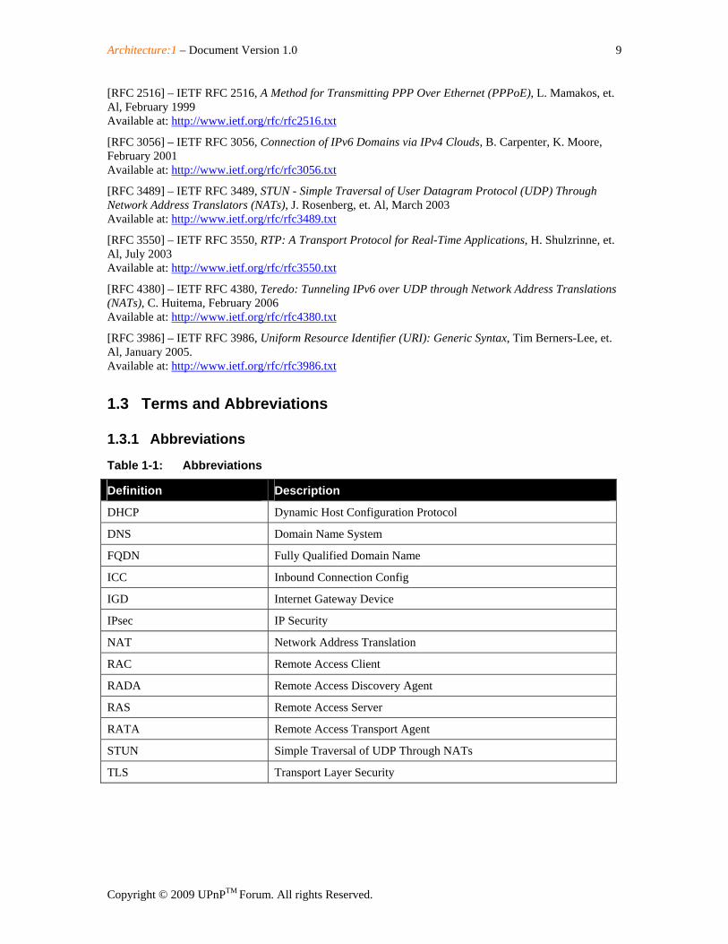
Table 1-1: Abbreviations
Definition Description
DHCP Dynamic Host Configuration Protocol
DNS Domain Name System
FQDN Fully Qualified Domain Name
ICC Inbound Connection Config
IGD Internet Gateway Device
IPsec IP Security
NAT Network Address Translation
RAC Remote Access Client
RADA Remote Access Discovery Agent
RAS Remote Access Server
RATA Remote Access Transport Agent
STUN Simple Traversal of UDP Through NATs
TLS Transport Layer Security
Architecture:1 – Document Version 1.0 10
Copyright © 2009 UPnPTM Forum. All rights Reserved.
1.3.2 Terms
1.3.2.1 Credentials The term credentials refer to certificates, shared secrets or other means of authentication used in the RATA context.
1.3.2.2 IPv6 Support in Transport Agents A Transport Agent is said to have IPv6 support if it allows the local and remote devices to interact according to the UPnP Device Architecture over IPv6 [DEVICE-IPv6].
1.3.2.3 Local Device A local device is a UPnP device that is attached to the physical network where the RADA is located.
1.3.2.4 Management Console The collection of control points that are used to setup, manage and monitor the operations related to Remote Access.
1.3.2.5 RADAListener The RADAListener is a logical support function of RADA and incorporates control point and device functionality for facilitating the SSDP offloading:
1.) The RADAListener establishes the initial state of its local network by performing an M-SEARCH to detect all devices on the local network and notifies the RADA of those devices.
2.) The RADAListener monitors the local SSDP traffic and notifies the RADA when devices are joining and leaving the UPnP network as described in the UPnP Device Architecture.
1.3.2.6 RADARelay The RADARelay is a logical support function of RADA and incorporates control point and device functionality for facilitating the SSDP offloading:
1.) For each device in the remote synchronization tree of the RADA, the RADARelay will send periodic SSDP announcements (e.g. ssdp:alive) onto the local network according the UPnP Device Architecture.
2.) Whenever a device is removed from the remote synchronization tree, the RADARelay will send an SSDP expiration (e.g. ssdp:byebye) onto the local network according the UPnP Device Architecture.
3.) Whenever a RADARelay receives an SSDP Search request (e.g. ssdp M-SEARCH) for a device or service that is contained in the remote synchronization tree, it will answer the search request on behalf of the device in the remote synchronization tree according the UPnP Device Architecture.
4.) When the remote connection is broken, the RADARelay will send an SSDP expiration (i.e. ssdp:byebye) on the local network for each remote device.
1.3.2.7 Remote Access Client The Remote Access Client (RAC) is the peer physical device that is not part of the physical home network. The RAC is exposing only the UPnP devices and services that are embedded in the physical device.
Architecture:1 – Document Version 1.0 11
Copyright © 2009 UPnPTM Forum. All rights Reserved.
1.3.2.8 Remote Access Network Interface The RA network interface is the network interface that is created by the Remote Access Transport Agent. The settings for this interface are contained in a RATA profile.
1.3.2.9 Remote Access Server The Remote Access Server (RAS) is the peer physical device located in the home network. RAS is exposing to the RAC the UPnP devices and services available in the physical home network as well as any embedded in the physical RAS device. The Remote Access Server can be the residential router, a personal computer or any 3rd party dedicated device.
1.3.2.10 Remote Access Transport Agent Profile A RATA profile is a configured RATA connection ready to be used by either accepting connections on the RAS side or to initiate connections on the RAC side.
1.3.2.11 Remote Device A remote device is a UPnP device that is not attached to the physical network where the RADA is located.
Architecture:1 – Document Version 1.0 12
Copyright © 2009 UPnPTM Forum. All rights Reserved.
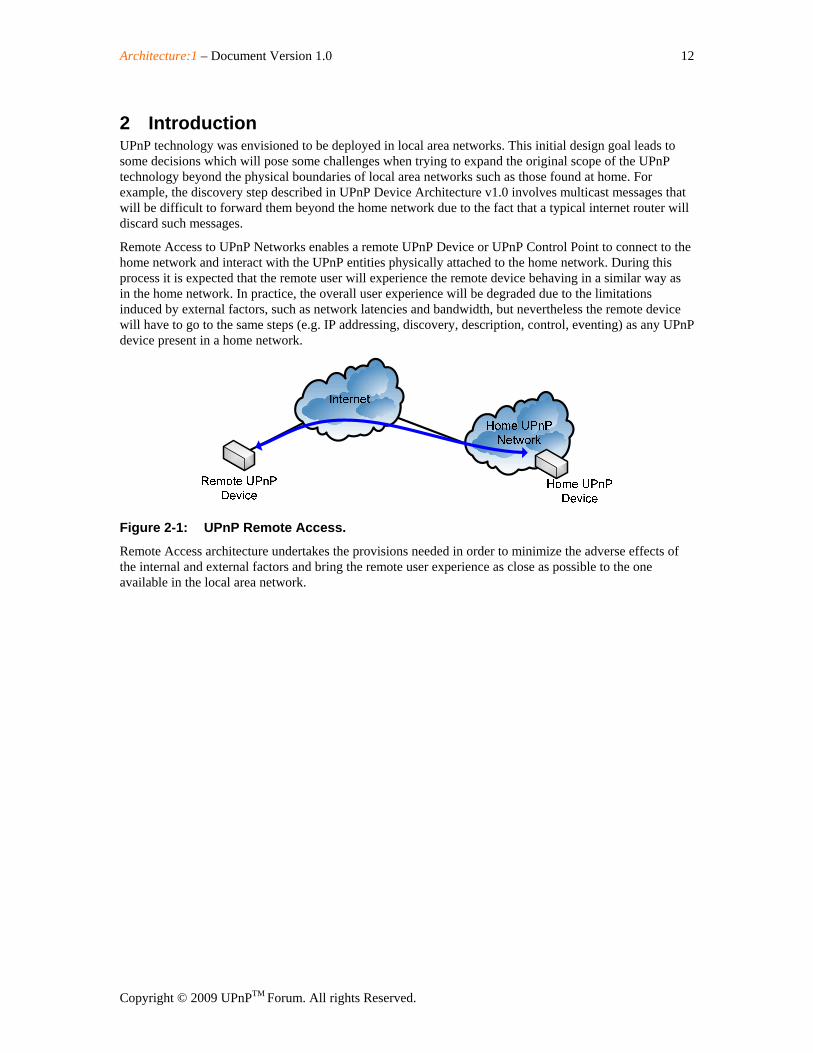
2 Introduction UPnP technology was envisioned to be deployed in local area networks. This initial design goal leads to some decisions which will pose some challenges when trying to expand the original scope of the UPnP technology beyond the physical boundaries of local area networks such as those found at home. For example, the discovery step described in UPnP Device Architecture v1.0 involves multicast messages that will be difficult to forward them beyond the home network due to the fact that a typical internet router will discard such messages.
Remote Access to UPnP Networks enables a remote UPnP Device or UPnP Control Point to connect to the home network and interact with the UPnP entities physically attached to the home network. During this process it is expected that the remote user will experience the remote device behaving in a similar way as in the home network. In practice, the overall user experience will be degraded due to the limitations induced by external factors, such as network latencies and bandwidth, but nevertheless the remote device will have to go to the same steps (e.g. IP addressing, discovery, description, control, eventing) as any UPnP device present in a home network.
Figure 2-1: UPnP Remote Access.
Remote Access architecture undertakes the provisions needed in order to minimize the adverse effects of the internal and external factors and bring the remote user experience as close as possible to the one available in the local area network.
Architecture:1 – Document Version 1.0 13
Copyright © 2009 UPnPTM Forum. All rights Reserved.
3 Operational Considerations
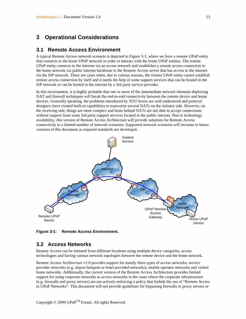
3.1 Remote Access Environment A typical Remote Access network scenario is depicted in Figure 3-1, where we have a remote UPnP entity that connects to the home UPnP network in order to interact with the home UPnP entities. The remote UPnP entity connects to the internet via an access network and establishes a remote access connection to the home network via public internet backbone to the Remote Access server that has access to the internet via the ISP network. There are cases when, due to various reasons, the remote UPnP entity cannot establish remote access connection by itself and it needs the help of some support services that can be hosted in the ISP network or can be hosted in the internet by a 3rd party service provider.
In this environment, it is highly probable that one or more of the intermediate network elements deploying NAT and firewall techniques will break the end-to-end connectivity between the remote device and home devices. Generally speaking, the problems introduced by NAT boxes are well understood and protocol designers have created built-in capabilities to transverse several NATs on the initiator side. However, on the receiving side, things are more complex and hosts behind NATs are not able to accept connections without support from some 3rd party support services located in the public internet. Due to technology availability, this version of Remote Access Architecture will provide solutions for Remote Access connectivity to a limited number of network scenarios. Supported network scenarios will increase in future versions of this document as required standards are developed.
AccessNetwork
ISP
Internet
HomeNetwork
Remote UPnPDevice
SupportServers
Home UPnPDevice
UPnP RemoteAccess
Gateway
Figure 3-1: Remote Access Environment.
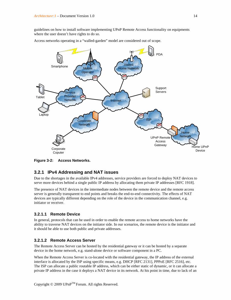
3.2 Access Networks Remote Access can be initiated from different locations using multiple device categories, access technologies and having various network topologies between the remote device and the home network.
Remote Access Architecture v1.0 provides support for mainly three types of access networks: service provider networks (e.g. airport hotspots or hotel provided networks), mobile operator networks and visited home networks. Additionally, the current version of the Remote Access Architecture provides limited support for using corporate networks as access networks in the cases where the corporate infrastructure (e.g. firewalls and proxy servers) are not actively enforcing a policy that forbids the use of “Remote Access to UPnP Networks”. This document will not provide guidelines for bypassing firewalls or proxy servers or
Architecture:1 – Document Version 1.0 14
Copyright © 2009 UPnPTM Forum. All rights Reserved.
guidelines on how to install software implementing UPnP Remote Access functionality on equipments where the user doesn’t have rights to do so.
Access networks operating in a “walled-garden” model are considered out of scope.
VisitedHome NetworkMobile
Operator
ServiceProviderNetwork
CorporateNetwork
ISP
Internet
HomeNetwork
SupportServers
Home UPnPDevice
UPnP RemoteAccess
Gateway
Laptop
Tablet
CorporateCoputer
Smartphone
PDA
Figure 3-2: Access Networks.
3.2.1 IPv4 Addressing and NAT issues Due to the shortages in the available IPv4 addresses, service providers are forced to deploy NAT devices to serve more devices behind a single public IP address by allocating them private IP addresses [RFC 1918].
The presence of NAT devices in the intermediate nodes between the remote device and the remote access server is generally transparent to end points and breaks the end-to-end connectivity. The effects of NAT devices are typically different depending on the role of the device in the communication channel, e.g. initiator or receiver.
3.2.1.1 Remote Device In general, protocols that can be used in order to enable the remote access to home networks have the ability to traverse NAT devices on the initiator side. In our scenarios, the remote device is the initiator and it should be able to use both public and private addresses.
3.2.1.2 Remote Access Server The Remote Access Server can be hosted by the residential gateway or it can be hosted by a separate device in the home network, e.g. stand-alone device or software component in a PC.
When the Remote Access Server is co-located with the residential gateway, the IP address of the external interface is allocated by the ISP using specific means, e.g. DHCP [RFC 2131], PPPoE [RFC 2516], etc. The ISP can allocate a public routable IP address, which can be either static of dynamic, or it can allocate a private IP address in the case it deploys a NAT device in its network. At his point in time, due to lack of an
Architecture:1 – Document Version 1.0 15
Copyright © 2009 UPnPTM Forum. All rights Reserved.
established standard mechanism to traverse the NAT boxes deployed in the ISP network, Remote Access Architecture v1.0 will support only the scenarios where the external interface of the residential gateway has a public routable IP address.
The other alternative is to have the Remote Access Server deployed in a stand alone device or in a PC. In this scenario the Remote Access Server acquires an IP address from the DHCP server located in the residential gateway. For this option to work, following requirements have been identified:
• Ability to add a UPnP device routing entry into the residential gateway is necessary (ideally using IGD from the RAS)
• RAS needs to support routing functionality
This version of the specification does not specify these mechanisms, which will be specified in the next version of the specifications.
Mechanisms to detect NAT presence in the ISP network and to inform the user about this situation are described in Section 4.4.1.2.
3.2.2 IPv6 Addressing If an access network provides native IPv6 connectivity, the Remote Access Client may use it depending on IPv6 support available in the home network. The Remote Access client may use IPv6 even if the access network is providing only IPv4 connectivity, via some generic IPv4-IPv6 transition mechnanisms, e.g. 6to4 [RFC 3056] or Teredo [RFC 4380].
3.3 Home Network Environment
3.3.1 IPv4 Support in Home Routers The Remote Access Architecture supports home networks having IPv4 connectivity. The home router may provide public or private IPv4 addresses to the home devices.
3.3.2 IPv6 Support in Home Routers The Remote Access Architecture supports home networks having IPv6 connectivity. The home router should provide 6to4 or native IPv6 addresses to the home devices.
3.4 Support Services in the Public Network
3.4.1 Server Name Resolution Dynamic DNS is a system for allowing an Internet domain name to be assigned to a varying IP address. This makes it possible for other sites on the Internet to establish connections to a machine having dynamic IP address (e.g. a cable or DSL service where the IP address of the modem is changed by the ISP occasionally), without needing to track the IP addresses themselves.
To implement dynamic DNS it is necessary to set a maximum caching time of the domain to an unusually short period (typically a few minutes). This prevents other sites on the Internet from retaining the old address in their cache, so that they will typically contact the name server of the domain for each new connection.
The use of the DNS is recommended, regardless if the IP address is static or dynamic, as IPv4/IPv6 addresses are too long to be typed by a user on a regular basis.
Architecture:1 – Document Version 1.0 16
Copyright © 2009 UPnPTM Forum. All rights Reserved.
3.4.2 Detecting NAT and NAT Type on Server Side A typical consumer is not aware if his ISP is deploying NAT boxes into its network or not. So, in order to determine if its network setup supports the Remote Access feature a mechanisms is needed to determine the presence of NAT boxes in the ISP network.
STUN [RFC 3489] is a network protocol allowing clients behind NAT (or multiple NATs) to find out its public address, the type of NAT it is behind and the internet side port associated by the NAT with a particular local port.
The STUN client embedded in the Remote Access Server sends a request to a STUN server. The server then reports back to the STUN client what the public IP address of the NAT router is, and what port was opened by the NAT to allow incoming traffic back in to the network. The response also allows the STUN client to determine what type of NAT is in use, as different types of NATs handle incoming UDP packets differently. It will work with three of four main types: full cone NAT, restricted cone NAT, and port restricted cone NAT. It will not work with symmetric NAT (also known as bi-directional NAT).
Remote Access Architecture v1.0 is using STUN to detect only the existence of the NAT in the ISP network and to inform the user that remote access connection cannot be established due to the ISP’s NAT boxes.
Remote Access will add support for traversing NAT devices in the ISP network in future releases as standard mechanisms to traverse symmetric NAT mature.
Architecture:1 – Document Version 1.0 17
Copyright © 2009 UPnPTM Forum. All rights Reserved.
4 Remote Access Reference Architecture
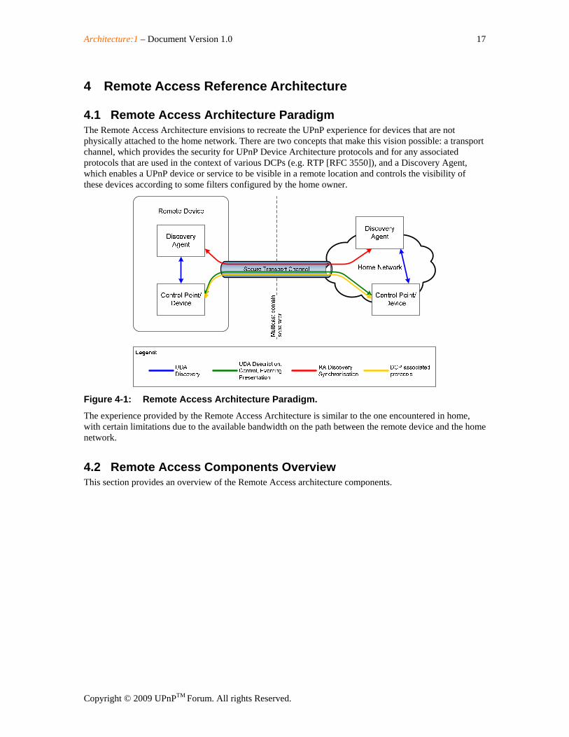
4.1 Remote Access Architecture Paradigm The Remote Access Architecture envisions to recreate the UPnP experience for devices that are not physically attached to the home network. There are two concepts that make this vision possible: a transport channel, which provides the security for UPnP Device Architecture protocols and for any associated protocols that are used in the context of various DCPs (e.g. RTP [RFC 3550]), and a Discovery Agent, which enables a UPnP device or service to be visible in a remote location and controls the visibility of these devices according to some filters configured by the home owner.
Figure 4-1: Remote Access Architecture Paradigm.
The experience provided by the Remote Access Architecture is similar to the one encountered in home, with certain limitations due to the available bandwidth on the path between the remote device and the home network.
4.2 Remote Access Components Overview This section provides an overview of the Remote Access architecture components.
Architecture:1 – Document Version 1.0 18
Copyright © 2009 UPnPTM Forum. All rights Reserved.
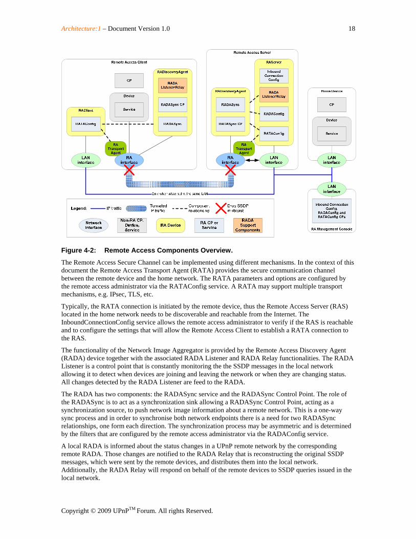
Figure 4-2: Remote Access Components Overview.
The Remote Access Secure Channel can be implemented using different mechanisms. In the context of this document the Remote Access Transport Agent (RATA) provides the secure communication channel between the remote device and the home network. The RATA parameters and options are configured by the remote access administrator via the RATAConfig service. A RATA may support multiple transport mechanisms, e.g. IPsec, TLS, etc.
Typically, the RATA connection is initiated by the remote device, thus the Remote Access Server (RAS) located in the home network needs to be discoverable and reachable from the Internet. The InboundConnectionConfig service allows the remote access administrator to verify if the RAS is reachable and to configure the settings that will allow the Remote Access Client to establish a RATA connection to the RAS.
The functionality of the Network Image Aggregator is provided by the Remote Access Discovery Agent (RADA) device together with the associated RADA Listener and RADA Relay functionalities. The RADA Listener is a control point that is constantly monitoring the the SSDP messages in the local network allowing it to detect when devices are joining and leaving the network or when they are changing status. All changes detected by the RADA Listener are feed to the RADA.
The RADA has two components: the RADASync service and the RADASync Control Point. The role of the RADASync is to act as a synchronization sink allowing a RADASync Control Point, acting as a synchronization source, to push network image information about a remote network. This is a one-way sync process and in order to synchronise both network endpoints there is a need for two RADASync relationships, one form each direction. The synchronization process may be asymmetric and is determined by the filters that are configured by the remote access administrator via the RADAConfig service.
A local RADA is informed about the status changes in a UPnP remote network by the corresponding remote RADA. Those changes are notified to the RADA Relay that is reconstructing the original SSDP messages, which were sent by the remote devices, and distributes them into the local network. Additionally, the RADA Relay will respond on behalf of the remote devices to SSDP queries issued in the local network.
Architecture:1 – Document Version 1.0 19
Copyright © 2009 UPnPTM Forum. All rights Reserved.
The multicast domain separation is done by the the routing module that prevents the UPnP multicast traffic to travel inside the remote access secure channel provided by RATA.
4.3 Remote Access Phases Overview This section describes when and how the Remote Access components are used.
4.3.1 Setup Services Before an UPnP device can be used remotely, the user has to configure the Remote Access Server and the Remote Access Client devices so that they can establish a Remote Access Transport channel between them. This step is considered to be the Remote Access Setup phase and usually takes place while both Remote Access Client and Remote Access Server are in the home network.
The Remote Access Architecture allows using multiple out-of-band mechanisms to enable the Remote Access Transport. In the context of this document, the functionality required for establishing the communication channel using the Remote Access Transport will be named the Remote Access Transport Agent (RATA). A different RATA is required for each RAT mechanism.
The Remote Access Architecture will provide a common configuration interface (e.g. RATAConfig) that will allow the configuration of each RATA. The interface will be the same for both RAC and RAS.
Additionally, in order to enable the reachability of the RAS from the internet the RAA will provide a configuration interface that will enable inbound connections, e.g. InboundConnectionConfig.
4.3.2 Operational Services The Remote Access Usage phase takes place immediately after the remote device has successfully established a connectivity channel over the RAT. In this phase, the standard devices, services and control points embedded in the RAC can communicate using the mechanisms provided by the UPnP Device Architecture with the corresponding devices, services and control points physically attached to the home network.
In order to make this step possible, the RAA provides a Remote Access Discovery Agent (RADA), which has the role of “mirroring” the discovery messages from the home network to the remote device and vice-versa. Additionally, the RADA may apply some filters that will restrict the visibility of the home devices or service from the remote control points or vice-versa.
The RADAs located in the RAC and the RAS communicate with each other using a synchronization SCPD which allows them to push updates to each other.
RADA is kept is sync with the status of the local UPnP network by RADA Listener, a component that is constantly monitoring the advertisements in the network and is informing the RADA when devices are joining or leaving.
Another support function of the RADA is the RADA Relay that performs the task of responding to discovery queries on behalf of a remote device. Another function of the RADA is to notify local devices when remote devices are joining or leaving the remote network. In order to perform thise two tasks, the RADA Relay is constantly checking the information on remote devices maintained by the RADA.
4.3.3 Management Service The RAA defines a management interfaces that allow the configuration of the Access Control Lists (ACL) that will restrict the visibility of the home devices from the remote control points (e.g. RADAConfig).
Architecture:1 – Document Version 1.0 20
Copyright © 2009 UPnPTM Forum. All rights Reserved.
4.4 Remote Access Functionalities
4.4.1 Inbound Connection Configuration This component provides the features that enable the end user to determine if a Remote Access Server can be deployed in the home network by checking if the Remote Access Server is reachable from the Internet.
4.4.1.1 Server Naming The lack of available IPv4 addresses prevents ISPs to allocate an IP address to each WAN interface of the residential gateways. To overcome this problem, service providers are dynamically allocating public IP addresses only to those gateways that are connected to the internet. This behavior will make difficult for an end user to connect to his home network when the IP addresses are dynamically allocated. The DNS System provides a way to associate IP addresses with Fully Qualified Domain Names, which are easily remembered by humans comparing to number sequences. Dynamic DNS is a system for allowing an Internet domain name to be assigned to a varying IP address.
A dynamic DNS client is colocated with the RAS so that the DNS server is notified whenever the IP address of the RAS has changed in order to update the DNS records with the latest information. When the RAS is not collocated with the residential gateway it can find the public address of the gateway using Internet Gateway Device means.
4.4.1.2 NAT Detection Shortages in the available IPv4 address have lead to the deployment of Network Address Translators. While providing many benefits, NATs also come with many drawbacks. The most troublesome of those drawbacks is the fact that it breaks the end-to-end connectivity which in turns breaks many IP applications.
Therefore, in a consumer environment such as the one encountered in the home UPnP network, it is of paramount importance to detect the elements what will hinder the establishment of the Remote Access connection.
Simple Traversal of UDP through NAT (STUN) is a lightweight protocol that allows applications to discover the presence and types of NATs and firewalls between them and the public Internet. It also provides the ability for applications to determine the public IP addresses allocated to them by the NAT. STUN works with many existing NATs, and does not require any special behavior from them. As a result, it allows a wide variety of applications to work through existing NAT infrastructure.
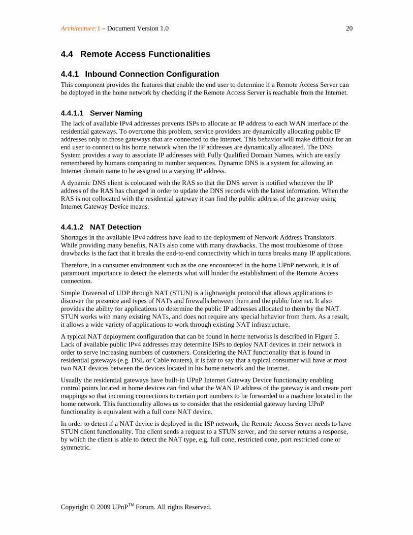
A typical NAT deployment configuration that can be found in home networks is described in Figure 5. Lack of available public IPv4 addresses may determine ISPs to deploy NAT devices in their network in order to serve increasing numbers of customers. Considering the NAT functionality that is found in residential gateways (e.g. DSL or Cable routers), it is fair to say that a typical consumer will have at most two NAT devices between the devices located in his home network and the Internet.
Usually the residential gateways have built-in UPnP Internet Gateway Device functionality enabling control points located in home devices can find what the WAN IP address of the gateway is and create port mappings so that incoming connections to certain port numbers to be forwarded to a machine located in the home network. This functionality allows us to consider that the residential gateway having UPnP functionality is equivalent with a full cone NAT device.
In order to detect if a NAT device is deployed in the ISP network, the Remote Access Server needs to have STUN client functionality. The client sends a request to a STUN server, and the server returns a response, by which the client is able to detect the NAT type, e.g. full cone, restricted cone, port restricted cone or symmetric.
Architecture:1 – Document Version 1.0 21
Copyright © 2009 UPnPTM Forum. All rights Reserved.
STUNServer
ISP NAT
Home NAT
Public Internet
ISP Private Network
Home Private Network
Remote Access GW(STUN Client)
Figure 4-3: Typical STUN Configuration in Home Networks
A simplified variation of this scenario is when the Remote Access Server is collocated with the residential gateway and the only NAT device of concern is the one potentially deployed in the ISP network.
A more restrictive scenario is typically found in apartment buildings which share the same internet connection for all users. In this scenario there might be an additional NAT device between the residential gateway and NAT deployed in the ISP network.
In the event of multiple NATs between the client and the Internet, the type that is discovered will be the type of the most restrictive NAT between the client and the Internet. The types of NAT, in order of restrictiveness, from most to least, are symmetric, port restricted cone, restricted cone, and full cone.
The current version of the Remote Access Architecture supports only full cone NAT between the Remote Access Server and the public Internet. Future versions of the Remote Access architecture will use the information collected through STUN to add support for traversing NAT devices in the ISP network, as standard mechanisms to traverse symmetric NAT mature.
4.4.2 Remote Access Discovery Agent
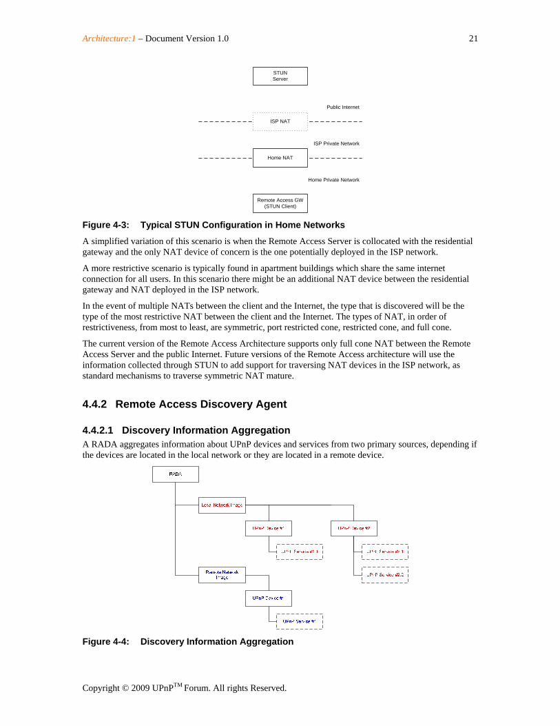
4.4.2.1 Discovery Information Aggregation A RADA aggregates information about UPnP devices and services from two primary sources, depending if the devices are located in the local network or they are located in a remote device.
Figure 4-4: Discovery Information Aggregation
Architecture:1 – Document Version 1.0 22
Copyright © 2009 UPnPTM Forum. All rights Reserved.
RADAListener, a support function of the RADA, is aggregating the devices and services available in the local network by constantly monitoring the SSDP announcements sent in the local network. The RADA Listener detects when devices are joining or leaving the network and notifies RADA about the changes, enabling the RADA to have an up-to-date image of the local UPnP network.
The RADA finds information about remote UPnP devices and services by synchronizing with remote RADA.
An RADA should keep the local and remote information separately. It might be possible that, in situations where multiple remote devices are connected to the same home network, the RADA keeps several branches of remote devices and services. The RADA should keep track of the identity of the remote entity for each remote branch.
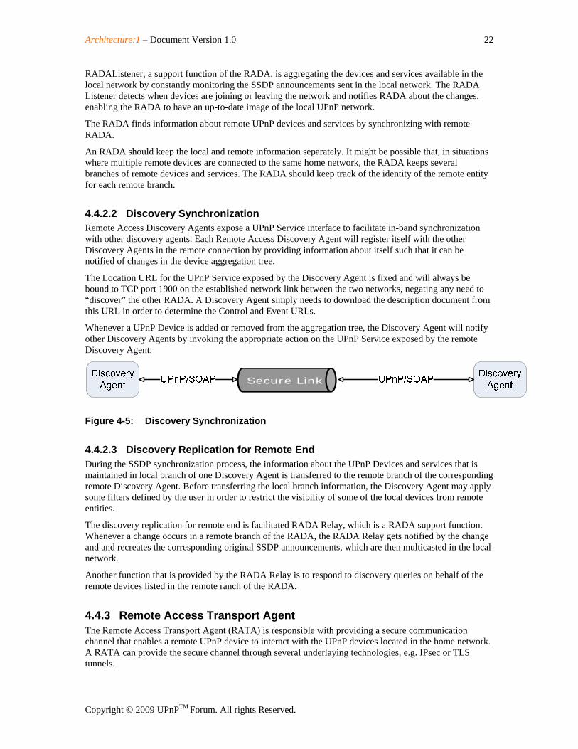
4.4.2.2 Discovery Synchronization Remote Access Discovery Agents expose a UPnP Service interface to facilitate in-band synchronization with other discovery agents. Each Remote Access Discovery Agent will register itself with the other Discovery Agents in the remote connection by providing information about itself such that it can be notified of changes in the device aggregation tree.
The Location URL for the UPnP Service exposed by the Discovery Agent is fixed and will always be bound to TCP port 1900 on the established network link between the two networks, negating any need to “discover” the other RADA. A Discovery Agent simply needs to download the description document from this URL in order to determine the Control and Event URLs.
Whenever a UPnP Device is added or removed from the aggregation tree, the Discovery Agent will notify other Discovery Agents by invoking the appropriate action on the UPnP Service exposed by the remote Discovery Agent.
Secure Link
Figure 4-5: Discovery Synchronization
4.4.2.3 Discovery Replication for Remote End During the SSDP synchronization process, the information about the UPnP Devices and services that is maintained in local branch of one Discovery Agent is transferred to the remote branch of the corresponding remote Discovery Agent. Before transferring the local branch information, the Discovery Agent may apply some filters defined by the user in order to restrict the visibility of some of the local devices from remote entities.
The discovery replication for remote end is facilitated RADA Relay, which is a RADA support function. Whenever a change occurs in a remote branch of the RADA, the RADA Relay gets notified by the change and and recreates the corresponding original SSDP announcements, which are then multicasted in the local network.
Another function that is provided by the RADA Relay is to respond to discovery queries on behalf of the remote devices listed in the remote ranch of the RADA.
4.4.3 Remote Access Transport Agent The Remote Access Transport Agent (RATA) is responsible with providing a secure communication channel that enables a remote UPnP device to interact with the UPnP devices located in the home network. A RATA can provide the secure channel through several underlaying technologies, e.g. IPsec or TLS tunnels.
Architecture:1 – Document Version 1.0 23
Copyright © 2009 UPnPTM Forum. All rights Reserved.
The two parties involved in the Remote Access agree on a common Remote Access transport mechanism with matching capabilities before a connection could be established. This is done by the management console. The Remote Access Architecture provides a configuration interface for the configuration of RATAs in the form of RATAConfig service.
Architecture:1 – Document Version 1.0 24
Copyright © 2009 UPnPTM Forum. All rights Reserved.
5 Interaction Model
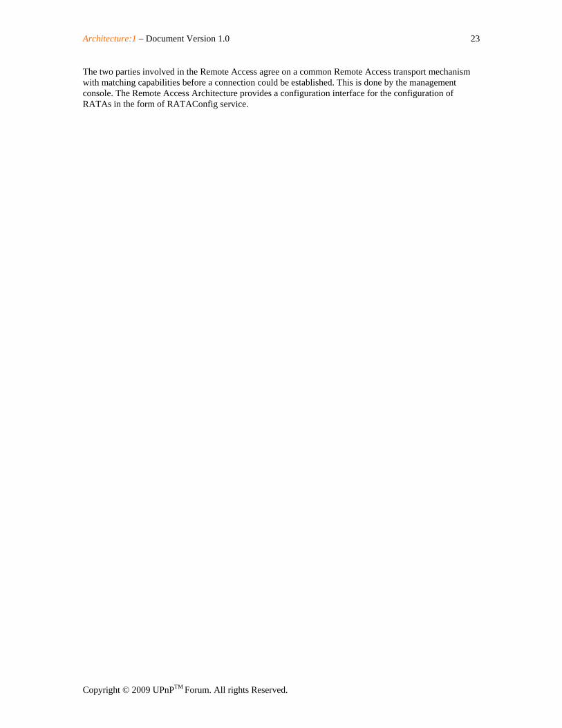
5.1 UPnP RA Setup
Figure 5-1: Remote Access Setup.
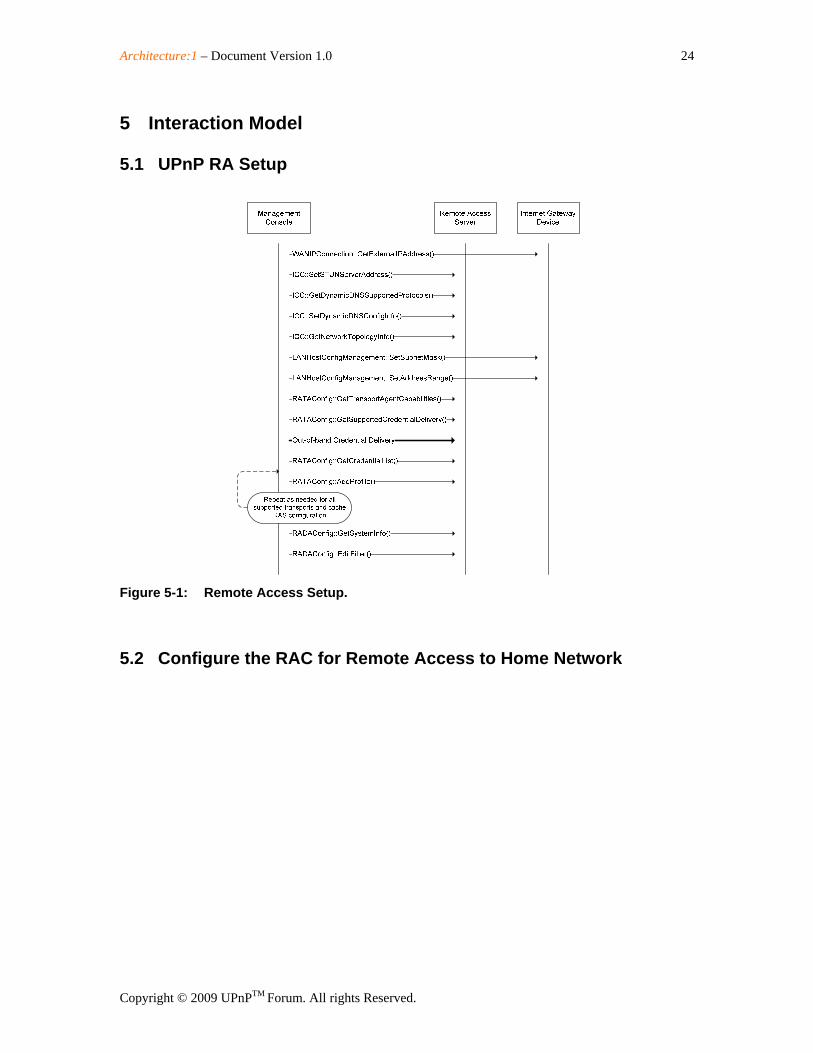
5.2 Configure the RAC for Remote Access to Home Network
Architecture:1 – Document Version 1.0 25
Copyright © 2009 UPnPTM Forum. All rights Reserved.
Figure 5-2: Configure the RAC for Remote Access to Home Network
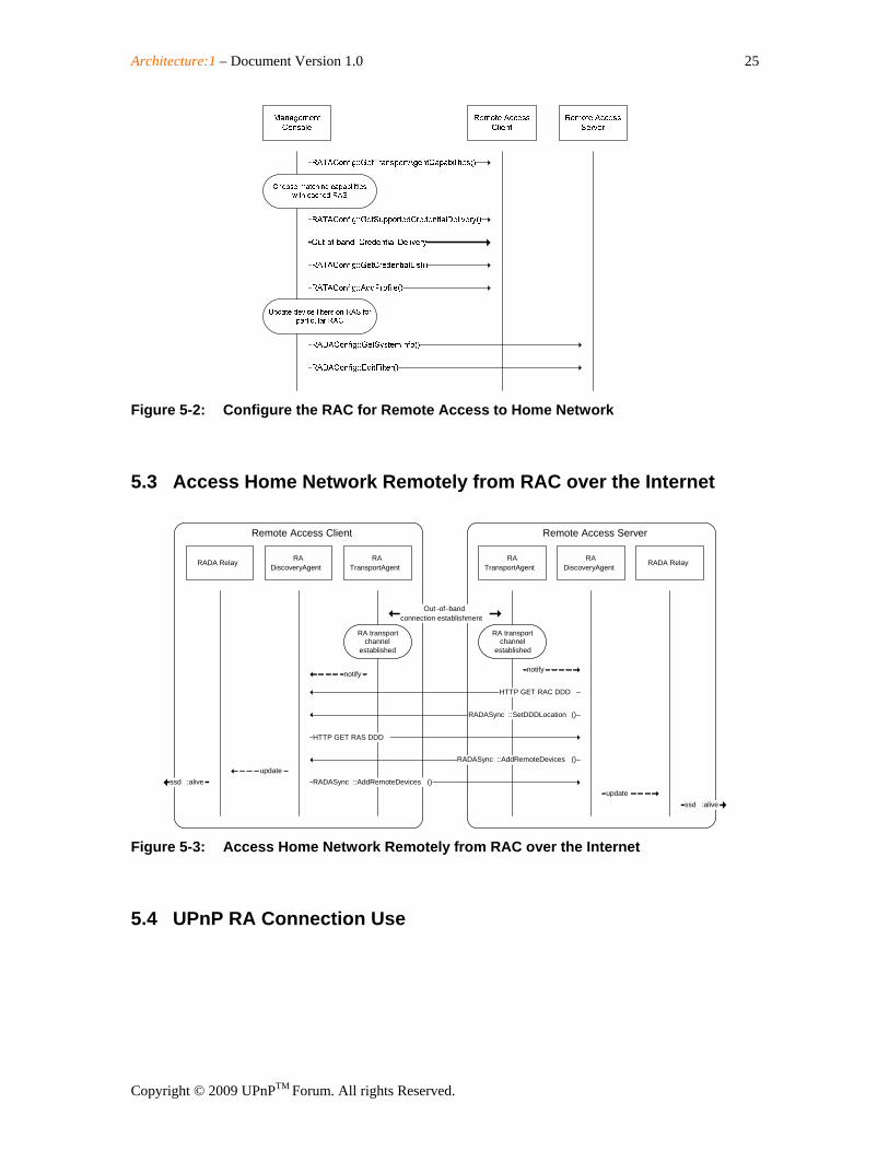
5.3 Access Home Network Remotely from RAC over the Internet
Figure 5-3: Access Home Network Remotely from RAC over the Internet
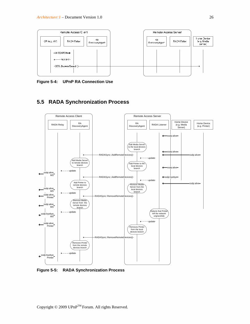
5.4 UPnP RA Connection Use
Remote Access Client Remote Access Server
HTTP GET RAS DDD
RADiscoveryAgent
RA DiscoveryAgent
RADASync ::SetDDDLocation ()
HTTP GET RAC DDD
RADASync ::AddRemoteDevices ()
RADASync :: AddRemoteDevices ()
RADA Relay RADA Relay
ssd : aliveupdate
update ssd : alive
RA transport channel
established
Out -of-bandconnection establishment
RATransportAgent
RATransportAgent
RA transport channel
established
notifynotify
Architecture:1 – Document Version 1.0 26
Copyright © 2009 UPnPTM Forum. All rights Reserved.
Figure 5-4: UPnP RA Connection Use
5.5 RADA Synchronization Process
Remote Access ServerRemote Access Client
RA DiscoveryAgent
RA DiscoveryAgent
RADASync::AddRemoteDevices()
RADA Relay RADA Listener
update
ssdp:aliveMS
Add Media Server to remote devices
branch
Add Media Server to the local devices
branch
Home Device(e.g. Media
Server)
ssdp:alive
update
Home Device(e.g. Printer)
ssdp:alive
Add Printer to the local devices
branch
RADASync::AddRemoteDevices()
Add Printer to remote devices
branch
updatessdp:alive
Printer
ssdp:byebyeupdate
Remove Media Server from the
local devices branch
ssdp:alive
ssdp:alive
ssdp:aliveMS
RADASync::RemoveRemoteDevices()
Remove Media Server from the remote devices
branch
update
ssdp:aliveMS
ssdp:byebyeMS
ssdp:alive
Detects that Printer left the network
ungracefully
update
Removes Printer from the local
devices branch
RADASync::RemoveRemoteDevices()
Removes Printer from the remote devices branch
update
ssdp:alivePrinter
ssdp:byebyePrinter
Figure 5-5: RADA Synchronization Process
Architecture:1 – Document Version 1.0 27
Copyright © 2009 UPnPTM Forum. All rights Reserved.
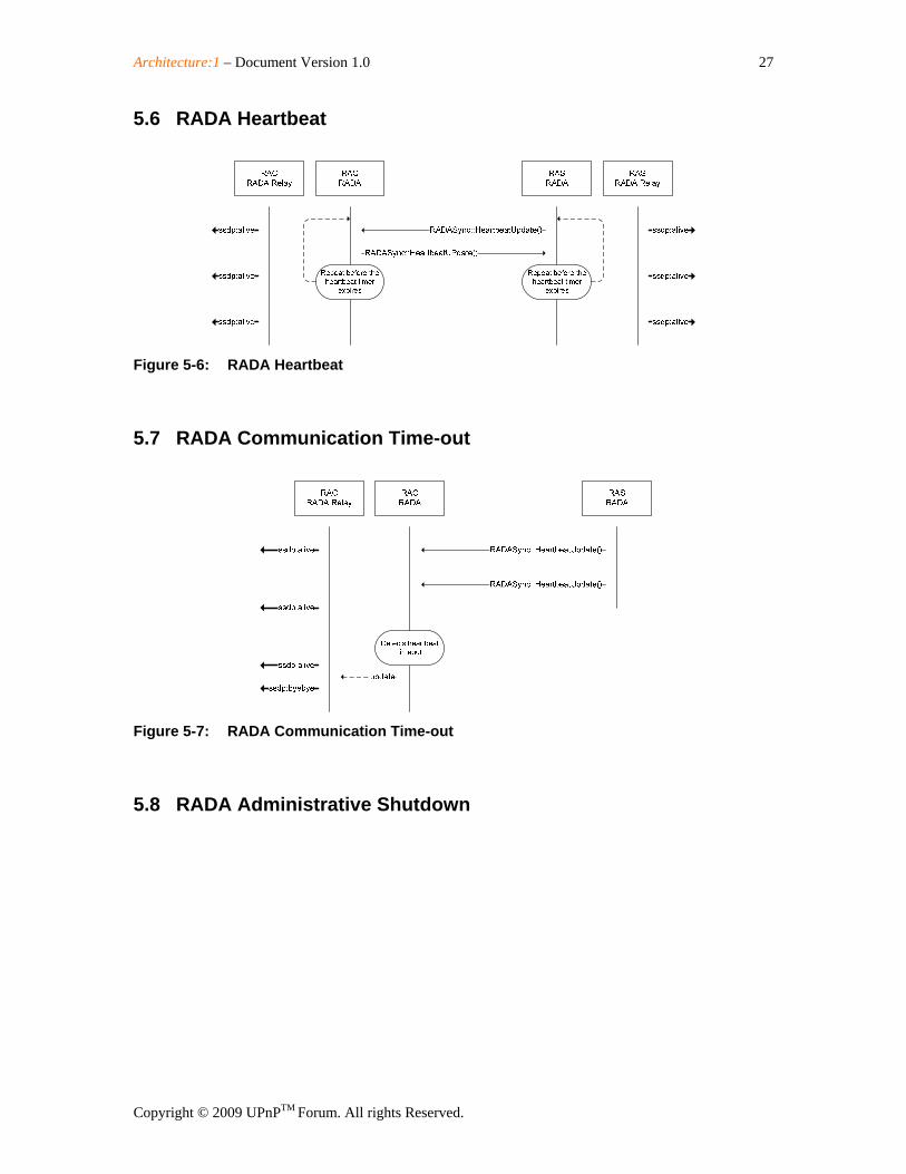
5.6 RADA Heartbeat
Figure 5-6: RADA Heartbeat
5.7 RADA Communication Time-out
Figure 5-7: RADA Communication Time-out
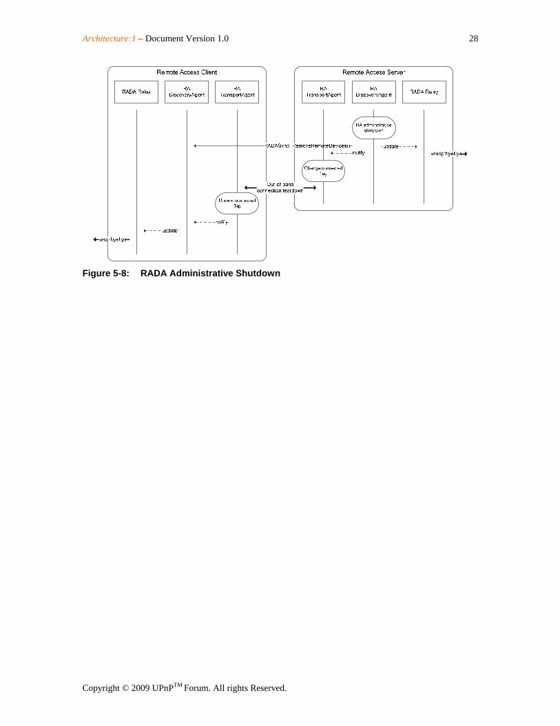
5.8 RADA Administrative Shutdown
Architecture:1 – Document Version 1.0 28
Copyright © 2009 UPnPTM Forum. All rights Reserved.
Figure 5-8: RADA Administrative Shutdown
Architecture:1 – Document Version 1.0 29
Copyright © 2009 UPnPTM Forum. All rights Reserved.
Appendix A. Deployment Scenarios
Architecture:1 – Document Version 1.0 30
Copyright © 2009 UPnPTM Forum. All rights Reserved.
A.1 Intended Deployment Scenarios
A.1.1 Remote Access Server in Residential Gateway In this (defacto) deployment scenario, the Remote Access Server is located in the Residential Gateway together with the Internet Gateway Device. This setup is the simplest as it provides for the RAS direct access to the hardware WAN interface of the residential gateway.
A.1.2 Remote Access Server in a 3rd Party Device In this (possible) deployment scenario, the Remote Access Server is located in a PC or in a standalone device other than the residential gateway. Comparing to the previous setup, the RAS has to take some actions to ensure that it is reachable from the internet and that the Remote Access transport can traverse the NAT deployed in the residential gateway. Additional considerations for this deployment scenario has been discussed in Section 3.2.1.2.
A.1.3 Remote Access Server Hosted by a 3rd Party in the Internet In this (potential) deployment scenario, the Remote Access Server is hosted in the ISP network or by a 3rd party provider in the internet. Typically, the RAS functionality is bundled with the other support services, e.g. DynDNS and STUN, and offered as a single service.