remote communication and control
TRANSCRIPT
SMP 300 Series • Remote Communication and Control 96
Remote Communication and Control
This section describes Simple Instruction Set (SIS) command programming and control of the SMP 300 Series, including:
• Connection Options
• Host-to-device Communications
• Using the Command and Response Tables
• Command and Response Tables
Connection OptionsThe SMP 300 Series can be configured and controlled using SIS commands or embedded web pages. Configure and control the SMP 300 Series remotely via a host computer or other device (such as a control system) by connecting to the rear panel RS-232 port, LAN port, or the front panel USB Config port of the SMP device.
RS-232 PortThe SMP 300 Series has a rear panel serial port (see figure 4, E on page 14) that can be connected to a host device such as a computer running a HyperTerminal utility, or the Extron DataViewer utility. The port makes serial control of the SMP possible. Use the protocol information listed above to make the connection Host-to-device Communications on page 98.
RS-232 protocol defaults:• 9600 baud • no parity • 1 stop bit• 8 data bits • no flow control
Front Panel Configuration PortThe mini B USB port is located on the front panel (see figure 8, B on page 20). Connect to a host computer for configuration using SIS commands with DataViewer, available at www.extron.com. To connect the SMP 300 Series to a host computer, download the USB driver, follow the on-screen instructions, and configure the SMP as required.
NOTE: If an Extron USB device has never been connected to the host computer, prior to connecting the SMP 300 Series config (USB) port for the first time, you must install and activate the USB driver. The simplest way to do this is to install Dataviewer (see DataViewer on page 128).

SMP 300 Series • Remote Communication and Control 97
Ethernet (LAN) PortThe rear panel LAN connector (see figure 4, Q on page 14) on the device can be connected to an Ethernet LAN or WAN. Communication between the device and the control system or PC is via Telnet (a TCP socket using port 23). The Telnet port can be changed, if necessary, via SIS or using the SMP 300 Series web UI. This connection makes SIS control of the device possible using a control system or PC connected to the same LAN or WAN.
LAN port defaults:DHCP: off
SMP 300 Series IP address: 192.168.254.254Subnet mask: 255.255.0.0Gateway IP address: 0.0.0.0
Ethernet ConnectionThe Ethernet cable can be terminated as a straight-through cable or a crossover cable and must be properly terminated for your application.
• Crossover cable — Direct connection between the computer and the SMP.
• Patch (straight) cable — Connection of the SMP to an Ethernet LAN.
12345678
RJ-45Connector
Insert TwistedPair Wires
Pins:
A cable that is wired as TIA/EIA T568A at one end and T568B at the other (Tx and Rx pairs reversed) is a "crossover" cable.
A cable wired the same at both ends is called a "straight-through" cable because no pin/pair assignments are swapped.
T568B T568A T568B T568B
Straight-through Cable(for connection to a switch, hub, or router)
End 1 End 2 Pin Wire Color Pin Wire Color
1 white-orange 1 white-orange 2 orange 2 orange 3 white-green 3 white-green 4 blue 4 blue 5 white-blue 5 white-blue 6 green 6 green 7 white-brown 7 white-brown 8 brown 8 brown
Crossover Cable(for direct connection to a PC)
End 1 End 2 Pin Wire Color Pin Wire Color
1 white-orange 1 white-green 2 orange 2 green 3 white-green 3 white-orange 4 blue 4 blue 5 white-blue 5 white-blue 6 green 6 orange 7 white-brown 7 white-brown 8 brown 8 brown
Figure 84. RJ-45 Ethernet Connector Pin Assignments
To establish a network connection to the SMP:
1. Open a TCP socket to port 23 using the SMP 300 Series IP address.
NOTE: If the local system administrators have not changed the value, the factory-specified default, 192.168.254.254, is the correct value for this field.
2. The SMP responds with a copyright message including the name of the product, firmware version, part number, and the current date and time.
a. If the SMP is not password-protected, the device is ready to accept SIS commands immediately after it sends the copyright message.
b. If the SMP is password-protected, a password prompt appears below the copyright message. Proceed to step 3.
3. If the device is password protected, enter the appropriate administrator or user password.
a. If the password is accepted, the device responds with Login User or Login Administrator.
b. If the password is not accepted, the Password prompt reappears.
NOTE: SSH connections may add an extra carriage return in the final terminator SIS responses, for example, standard is X1!] and SSH is X1!]].
figure 84

SMP 300 Series • Remote Communication and Control 98
Connection TimeoutsThe Ethernet link times out after a designated period of time with no communication. By default, this timeout value is 5 minutes, but the value can be changed.
NOTE: Extron recommends leaving the default timeout at 5 minutes and periodically issuing the Query (Q) command to keep the connection active. If there are long idle periods, disconnect the socket and reopen the connection when another command must be sent.
Verbose ModeTelnet connections can be used to monitor for changes that occur, such as SIS commands from other Telnet sockets or serial port changes. For a Telnet session to receive change notices, the Telnet session must be in verbose mode 1 or 3. In verbose mode 1 or 3, the Telnet socket reports changes in messages that resemble SIS command responses. Front panel changes are also sent to users who are in verbose mode.
Host-to-device CommunicationsSIS commands consist of one or more characters per command field. They do not require special characters to begin or end the command sequence. Each response to an SIS command ends with a carriage return and a line feed (CR/LF = ]), which signals the end of the response character string. A string is one or more characters.
SMP 300 Series-initiated MessagesThe SMP 300 Series initiates messages under specific conditions. No response is required from the host. The SMP 300 Series initiated messages are listed here.
]© Copyright 2014-2017, Extron Electronics, SMP 351, Vn.nn, 60– 1324-01]
Day, DD MMM YYYY HH:MM:SS]or
]© Copyright 2014-2017, Extron Electronics, SMP 351 3G-SDI, Vn.nn, 60– 1324-02]
Day, DD MMM YYYY HH:MM:SS]or
]© Copyright 2014-2017, Extron Electronics, SMP 352, Vn.nn, 60–1634-11]
Day, DD MMM YYYY HH:MM:SS]
or
]© Copyright 2014-2017, Extron Electronics, SMP 352 3G-SDI, Vn.nn, 60–1634-12]
Day, DD MMM YYYY HH:MM:SS]
Vn.nn is the firmware version number.
The SMP sends the copyright messages under the following circumstances:
• If the SMP is off and an RS-232 connection is already set up (the PC is cabled to the SMP and a serial communication program such as HyperTerminal is open), the connected unit sends these messages via RS-232 when first powered on.
• If the SMP is on, it sends the copyright messages when a Telnet connection to the SMP is first opened. The day of the week, date, and time are shown when the SMP is connected via Telnet, but not via RS-232. If using a Telnet connection, the copyright message, date, and time may be followed by a password prompt.

SMP 300 Series • Remote Communication and Control 99
Password InformationThe ]Password: prompt requires a password (administrator level or user level) followed by a carriage return. The prompt is repeated if the correct password is not entered.
If the correct password is entered, the unit responds with ] Login Administrator ] or ] Login User ], depending on the password entered. If passwords are the same for both administrator and user, the unit defaults to administrator privileges.
Error ResponsesWhen the SMP is unable to execute the command, it returns an error response to the host. The error response codes and their descriptions are as follows:
E10 – Unrecognized command E18 – System timed out
E12 – Invalid port number E22 – Busy
E13 – Invalid parameter (number is out of range)
E24 – Privilege violation
E14 – Not valid for this configuration E26 – Maximum connections exceeded
E17 – Invalid command for signal type E28 – Bad file name or file not found
Using the Command and Response TablesThe Command and Response Tables on page 104. Symbols used in the table represent variables in the command and response fields. Command and response examples are shown throughout the table. The SIS commands are not case sensitive. The ASCII to Hex conversion table below is for use with the command and response table.
ASCII to Hex Conversion Table
•
Space
Figure 85. ASCII to Hex Conversion
figure 85

SMP 300 Series • Remote Communication and Control 100
Symbol definitions] = CR/LF (carriage return/line feed)
} or ¦ = Carriage return or pipe symbol (no line feed, hex 0D)
• = SpaceE or W = Escape
X! = Inputs 1 to 4 (1 to 5 for SDI models)X* = Status
0 = Offline 1 = Live
X( = 0 = Disabled/unassigned/off/unmuted (default) 1 = Enabled/assigned/on/muted
X1) = Configuration type 0 = IP Config (ip.cfg) 2 = Box specific parameters (box.cfg)
X1! = Firmware version numberX1@ = Device name (63 characters, max)
Must comply with internet host name standards.
X1# = Day, date, and time (Day,•MM•DD•YY-HH:MM:SS)
X1$ = Time zone acronym (2 to 6 letters)X1% = Greenwich Mean Time (GMT) offset value:
-12:00 to 14:00. Represents hours and minutes (HH:MM) offset from GMT including the time zone name.
X1^ = IP address in dotted decimal notation (xxx.xxx.xxx.xxx) Default IP address: 192.168.254.254 (no padding) Default gateway IP address: 0.0.0.0 Default DNS server IP address: 0.0.0.0
X1& = Subnet mask Default: 255.255.0.0 (no padding)
X1* = Hardware MAC address (00-05-A6-NN-NN-NN)
X1( Time in tens of milliseconds to wait for characters coming into a serial port before terminating (min = 0, max = 32767 and, default = 10 = 100 ms). The response is returned with leading zeros.
X2) Time in tens of milliseconds to wait between characters coming into a serial port before terminating (min = 0, max = 32767, and default = 2 = 20 ms). The response is returned with leading zeros. Commands using both X1& and X2) must have both values = 0 or both set to non-zero.
X2! = Parameter to set either Length of message to receive or Delimiter value. L=#=byte count (min = 0, max = 32767, default = 0L = 0 byte count).
D = Decimal value for ASCII character. (min = 0, max = 00255, default = 00000L). Value is placed prior to parameter: 3 byte length = 3L and ASCII 0A delimiter is 10D. The parameter is case sensitive, and must use capital D or capital L. The response is returned with leading zeros.
X2@ = Priority status for receiving timeouts — 0 = Use Send data string command parameters (if they exist) (default). 1 = Use Configure receive timeout command parameters instead.
X2# = Verbose mode 0 = Clear/none (default for Telnet
connections)1 = Verbose mode (default for USB and
RS-232 host control)2 = Tagged responses for queries3 = Verbose mode and tagged responses
for queriesX2% = RS-232 baud rate (9600 [default], 19200,
38400, 57600, 115200)X2^ = RS-232 parity — single letter:
Odd, Even, None (default), Mark, SpaceX2& = RS-232 data bits — 7, 8 (default)X2* = RS-232 stop bits — 1 (default), 2X3) = Audio format
0 = Disable audio 1 = Analog (default of input 3) 2 = PLCM 2 CH (default)
X3# = Password — Maximum length 128 characters. All alpha-numeric characters permitted except |, and "space".
X4) = Encode profile 1 = Base 2 = Main 3 = High
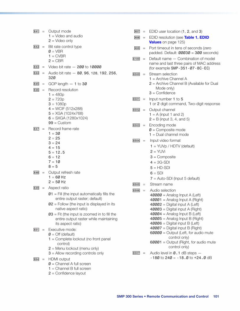
SMP 300 Series • Remote Communication and Control 101
X4! = Output mode 1 = Video and audio 2 = Video only
X4@ = Bit rate control type 0 = VBR 1 = CVBR 2 = CBR
X4# = Video bit rate — 200 to 10000X4$ = Audio bit rate — 80, 96, 128, 192, 256,
320X4% = GOP length — 1 to 30X4^ = Record resolution
1 = 480p 2 = 720p 3 = 1080p 4 = WCIF (512x288) 5 = XGA (1024x768) 6 = SXGA (1280x1024) 99 = Custom
X4& = Record frame rate 1 = 30 2 = 25 3 = 24 4 = 15 5 = 12.5 6 = 12 7 = 10 8 = 5
X4* = Output refresh rate 1 = 60 Hz 2 = 50 Hz
X4( = Aspect ratio
01 = Fill (the input automatically fills the entire output raster; default)
02 = Follow (the input is displayed in its native aspect ratio)
03 = Fit (the input is zoomed in to fill the entire output raster while maintaining its aspect ratio)
X5! = Executive mode: 0 = Off (default) 1 = Complete lockout (no front panel control) 2 = Menu lockout (menu only) 3 = Allow recording controls only
X6$ = HDMI output 0 = Channel A full screen 1 = Channel B full screen 2 = Confidence layout
X6& = EDID user location (1, 2, and 3)X6* = EDID resolution (see Table 1. EDID
Values on page 125)X6( = Port timeout in tens of seconds (zero
padded. Default: 00030 = 300 seconds)X10) = Default name — Combination of model
name and last three pairs of MAC address (for example SMP-351-07-8C-EC)
X50) = Stream selection 1 = Archive Channel A 2 = Archive Channel B (Available for Dual Mode only) 3 = Confidence
X50! = Input number 1 to 5 1 or 2 digit command, Two-digit response
X50@ = Output channel 1 = A (input 1 and 2) 2 = B (input 3, 4, and 5)
X50# = Encoding mode 0 = Composite mode 1 = Dual channel mode
X50$ = Input video format1 = YUVp / HDTV (default)2 = YUVi 3 = Composite4 = 3G-SDI5 = HD-SDI 6 = SDI7 = Auto-SDI (Input 5 default)
X50% = Stream nameX50^ = Audio selection
40000 = Analog Input A (Left) 40001 = Analog Input A (Right) 40002 = Digital input A (Left) 40003 = Digital input A (Right) 40004 = Analog Input B (Left) 40005 = Analog Input B (Right) 40006 = Digital input B (Left) 40007 = Digital input B (Right) 60000 = Output (Left, for audio mute control only) 60001 = Output (Right, for audio mute control only)
X50& = Audio level in 0.1 dB steps — -180 to 240 = -18.0 to +24.0 dB
SMP 300 Series • Remote Communication and Control 102
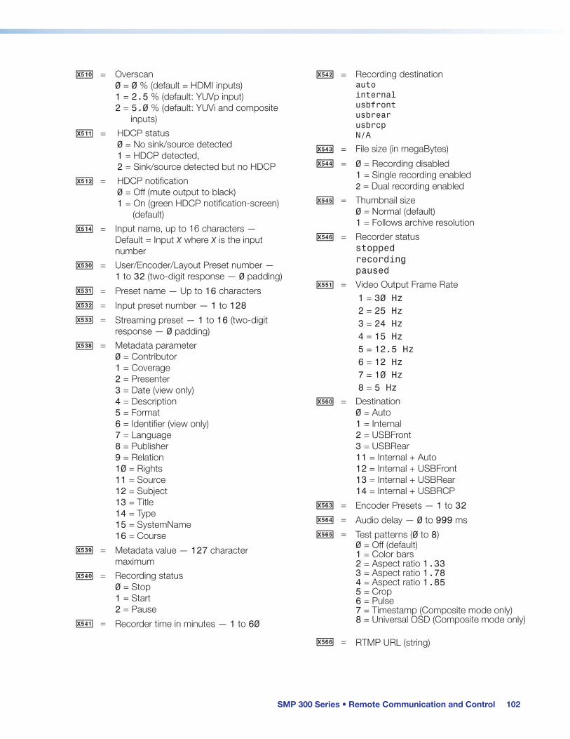
X51) = Overscan 0 = 0 % (default = HDMI inputs) 1 = 2.5 % (default: YUVp input) 2 = 5.0 % (default: YUVi and composite inputs)
X51! = HDCP status 0 = No sink/source detected 1 = HDCP detected, 2 = Sink/source detected but no HDCP
X51@ = HDCP notification 0 = Off (mute output to black) 1 = On (green HDCP notification-screen) (default)
X51$ = Input name, up to 16 characters — Default = Input X where X is the input number
X53) = User/Encoder/Layout Preset number — 1 to 32 (two-digit response — 0 padding)
X53! = Preset name — Up to 16 charactersX53@ = Input preset number — 1 to 128X53# = Streaming preset — 1 to 16 (two-digit
response — 0 padding)X53* = Metadata parameter
0 = Contributor 1 = Coverage 2 = Presenter 3 = Date (view only) 4 = Description 5 = Format 6 = Identifier (view only) 7 = Language 8 = Publisher 9 = Relation 10 = Rights 11 = Source 12 = Subject 13 = Title 14 = Type 15 = SystemName 16 = Course
X53( = Metadata value — 127 character maximum
X54) = Recording status 0 = Stop 1 = Start 2 = Pause
X54! = Recorder time in minutes — 1 to 60
X54@ = Recording destinationauto internal usbfront usbrear usbrcp N/A
X54# = File size (in megaBytes)X54$ = 0 = Recording disabled
1 = Single recording enabled2 = Dual recording enabled
X54% = Thumbnail size 0 = Normal (default)1 = Follows archive resolution
X54^ = Recorder status stopped recording paused
X55! = Video Output Frame Rate1 = 30 Hz2 = 25 Hz3 = 24 Hz4 = 15 Hz5 = 12.5 Hz6 = 12 Hz7 = 10 Hz8 = 5 Hz
X56) = Destination 0 = Auto 1 = Internal 2 = USBFront 3 = USBRear 11 = Internal + Auto 12 = Internal + USBFront 13 = Internal + USBRear 14 = Internal + USBRCP
X56# = Encoder Presets — 1 to 32X56$ = Audio delay — 0 to 999 msX56% = Test patterns (0 to 8)
0 = Off (default) 1 = Color bars 2 = Aspect ratio 1.33 3 = Aspect ratio 1.78 4 = Aspect ratio 1.85 5 = Crop 6 = Pulse 7 = Timestamp (Composite mode only) 8 = Universal OSD (Composite mode only)
X56^ = RTMP URL (string)

SMP 300 Series • Remote Communication and Control 103
X56& = Audio output 1 = Channel A only (Dual mono disable only) 2 = Channel B only (Dual mono disable only) 3 = Channel A + Channel B (Dual mono disable only) 4 = Channel A + Channel B dual mono (Dual mono enabled only) 5 = Channel A dual mono + Channel B (Dual mono enabled only)
X58! = Front panel audio level indication -1500 to 0 Full bars = 0 No bars = <-600 Format: left*right Example: -58*-63
X58@ = Recording mode 0 = Channel A disabled 1 = Single Recording in Composite mode 2 = Internal + Secondary Recording in Composite mode
X59! = USB Storage 0 = All USB storage 2 = USBFront 3 = USBRear 4 = USBRCP
X59@ = Valid DB_ID number (integer)X60# = Pixel phase adjustment — 0 to 63
(default = 32)X60$ = Horizontal and vertical start — 0 to 255
(default = 128)X60% = Total pixels — Up to + 512 of the default
value for the detected rateX60^ = Active lines — Up to + 256 of the default
value for the detected resolution (range varies based on input resolution)
X60& = Active pixels — Up to + 512 of the default value for the detected resolution (range varies based on input resolution)
X60* = Picture adjust — 0 to 127 Default = 64
X60( = Horizontal centering — Varies based on archive resolution
X61! = Vertical centering — Varies based on archive resolution
X61@ = Horizontal size — 120 to 4096X61# = Vertical size — 64 to 4096X62! = SNMP contact name text, up to 64
characters (default = Not Specified)X62@ = SNMP location, up to 64 characters
(default = Not Specified)
X62# = SNMP public community string, up to 64 characters (default = public)
X62$ = SNMP private community string, up to 64 characters (default = private)
NOTE: SNMP names and community strings can be up to 64 alphanumeric characters including hyphens, underscores and periods.
SMP 300 Series • Remote Communication and Control 104
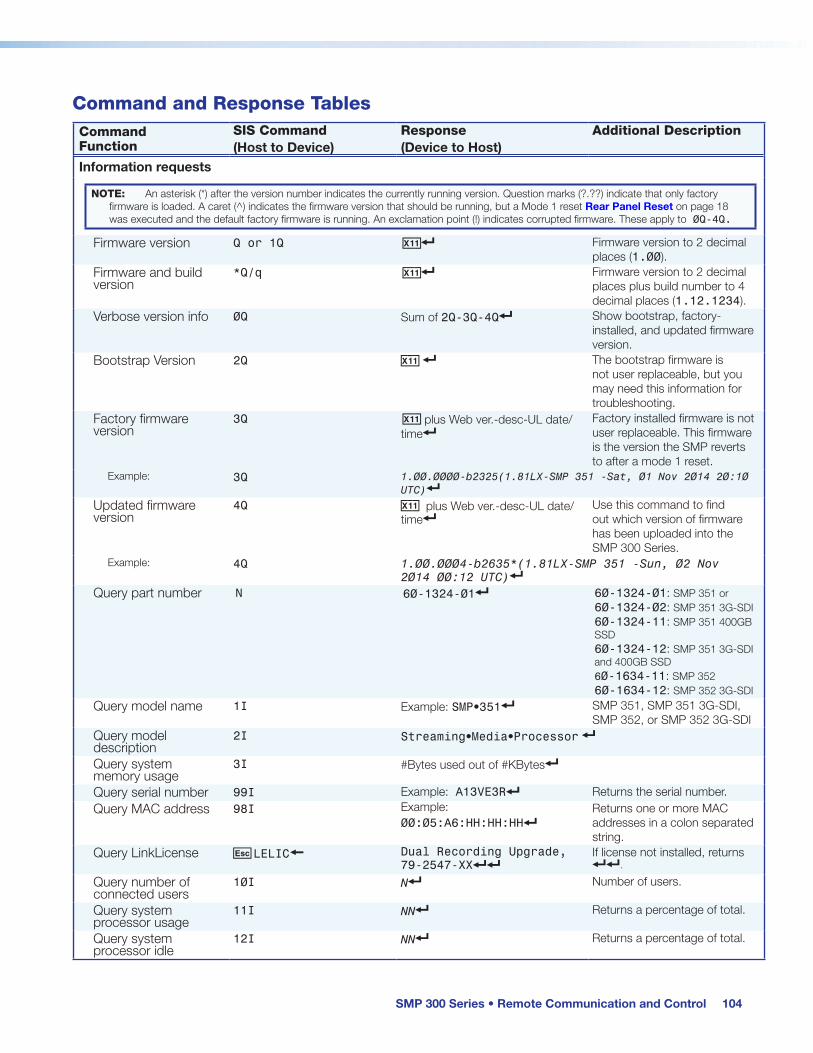
Command and Response TablesCommand Function
SIS Command(Host to Device)
Response(Device to Host)
Additional Description
Information requests
NOTE: An asterisk (*) after the version number indicates the currently running version. Question marks (?.??) indicate that only factory firmware is loaded. A caret (^) indicates the firmware version that should be running, but a Mode 1 reset Rear Panel Reset on page 18 was executed and the default factory firmware is running. An exclamation point (!) indicates corrupted firmware. These apply to 0Q-4Q.
Firmware version Q or 1Q X1!] Firmware version to 2 decimal places (1.00).
Firmware and build version
*Q/q X1!] Firmware version to 2 decimal places plus build number to 4 decimal places (1.12.1234).
Verbose version info 0Q Sum of 2Q-3Q-4Q] Show bootstrap, factory-installed, and updated firmware version.
Bootstrap Version 2Q X1! ] The bootstrap firmware is not user replaceable, but you may need this information for troubleshooting.
Factory firmware version
3Q X1! plus Web ver.-desc-UL date/time]
Factory installed firmware is not user replaceable. This firmware is the version the SMP reverts to after a mode 1 reset.
Example: 3Q 1.00.0000-b2325(1.81LX-SMP 351 -Sat, 01 Nov 2014 20:10 UTC)]
Updated firmware version
4Q X1! plus Web ver.-desc-UL date/time]
Use this command to find out which version of firmware has been uploaded into the SMP 300 Series.
Example: 4Q 1.00.0004-b2635*(1.81LX-SMP 351 -Sun, 02 Nov 2014 00:12 UTC)]
Query part number N 60-1324-01] 60-1324-01: SMP 351 or 60-1324-02: SMP 351 3G-SDI 60-1324-11: SMP 351 400GB SSD 60-1324-12: SMP 351 3G-SDI and 400GB SSD 60-1634-11: SMP 352 60-1634-12: SMP 352 3G-SDI
Query model name 1I Example: SMP•351] SMP 351, SMP 351 3G-SDI, SMP 352, or SMP 352 3G-SDI
Query model description
2I Streaming•Media•Processor ]
Query system memory usage
3I #Bytes used out of #KBytes]
Query serial number 99I Example: A13VE3R] Returns the serial number.Query MAC address 98I Example:
00:05:A6:HH:HH:HH]Returns one or more MAC addresses in a colon separated string.
Query LinkLicense E LELIC} Dual Recording Upgrade, 79-2547-XX]]
If license not installed, returns ]].
Query number of connected users
10I N] Number of users.
Query system processor usage
11I NN] Returns a percentage of total.
Query system processor idle
12I NN] Returns a percentage of total.
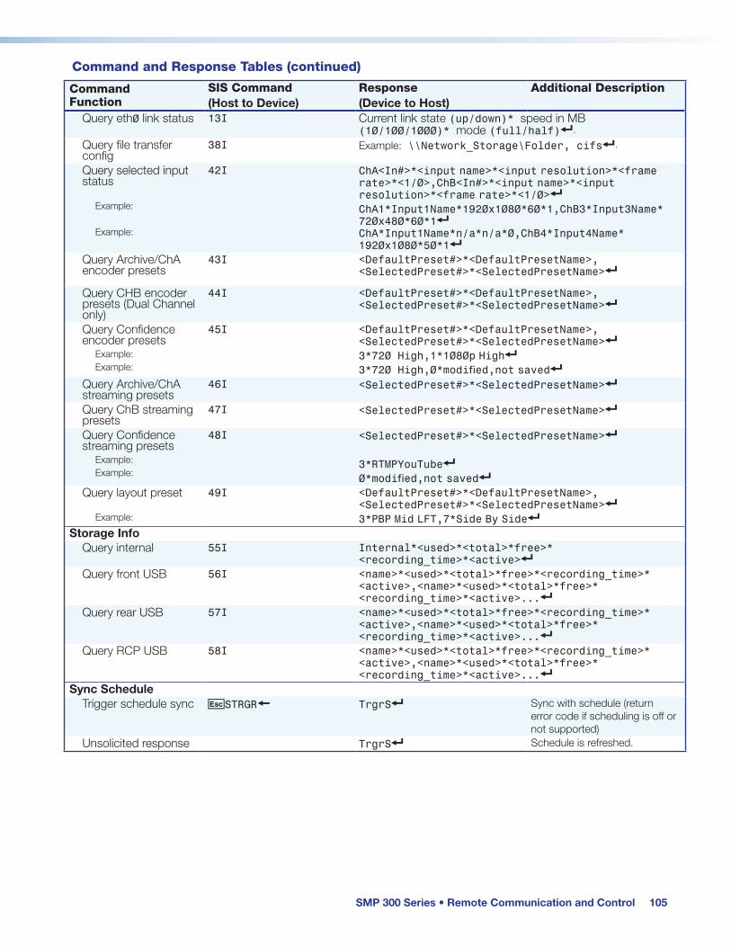
SMP 300 Series • Remote Communication and Control 105
Command and Response Tables (continued)
Command Function
SIS Command(Host to Device)
Response(Device to Host)
Additional Description
Query eth0 link status 13I Current link state (up/down)* speed in MB (10/100/1000)* mode (full/half)].
Query file transfer config
38I Example: \\Network_Storage\Folder, cifs].
Query selected input status
Example:
Example:
42I ChA<In#>*<input name>*<input resolution>*<frame rate>*<1/0>,ChB<In#>*<input name>*<input resolution>*<frame rate>*<1/0>]ChA1*Input1Name*1920x1080*60*1,ChB3*Input3Name* 720x480*60*1] ChA*Input1Name*n/a*n/a*0,ChB4*Input4Name* 1920x1080*50*1]
Query Archive/ChA encoder presets
43I <DefaultPreset#>*<DefaultPresetName>, <SelectedPreset#>*<SelectedPresetName>]
Query CHB encoder presets (Dual Channel only)
44I <DefaultPreset#>*<DefaultPresetName>, <SelectedPreset#>*<SelectedPresetName>]
Query Confidence encoder presets
Example:Example:
45I <DefaultPreset#>*<DefaultPresetName>, <SelectedPreset#>*<SelectedPresetName>]3*720 High,1*1080p High]
ig o ifi not saved]Query Archive/ChA streaming presets
46I <SelectedPreset#>*<SelectedPresetName>]
Query ChB streaming presets
47I <SelectedPreset#>*<SelectedPresetName>]
Query Confidence streaming presets
Example:Example:
48I <SelectedPreset#>*<SelectedPresetName>]
3*RTMPYouTube]o ifi not saved]
Query layout preset
Example:
49I <DefaultPreset#>*<DefaultPresetName>, <SelectedPreset#>*<SelectedPresetName>]3*PBP Mid LFT,7*Side By Side]
Storage InfoQuery internal 55I Internal*<used>*<total>*free>*
<recording_time>*<active>]Query front USB 56I <name>*<used>*<total>*free>*<recording_time>*
<active>,<name>*<used>*<total>*free>* <recording_time>*<active>...]
Query rear USB 57I <name>*<used>*<total>*free>*<recording_time>* <active>,<name>*<used>*<total>*free>* <recording_time>*<active>...]
Query RCP USB 58I <name>*<used>*<total>*free>*<recording_time>* <active>,<name>*<used>*<total>*free>* <recording_time>*<active>...]
Sync ScheduleTrigger schedule sync ESTRGR} TrgrS] Sync with schedule (return
error code if scheduling is off or not supported)
Unsolicited response TrgrS] Schedule is refreshed.

SMP 300 Series • Remote Communication and Control 106
Command Function
SIS Command(Host to Device)
Response(Device to Host)
Additional Description
Clear active alarms ECALRM} Alrm C] Clear all active alarms.View active alarms 39I [name:alarm_name],[level:alarm_level]...]]
If no active alarms: None active]Set unit name E X1@ CN } Ipn X1@ ]Set unit name to default
E • CN} Ipn X10) ]
View unit name E CN } X1@ ]
View Telnet connections
E CC} N]
Icc N]
N = Number of active IP connections. Verbose mode 2/3
Set verbose mode E X2# CV} Vrb X2#]
View verbose mode E CV} X2#]
NOTE: If tagged responses is enabled, all read commands return the data, the same as setting the value does.
System CommandsBackup/Restore
Save configuration E 1* X1) XF} Cfg1* X1) ] Save configuration to file location (/nortxe-backup).
Restore configuration E 0* X1) XF} Cfg0* X1) ] Load configuration from file location (/nortxe-backup).
ResetsReboot system E 1BOOT} Boot1] Complete system reboot.
Restart the network E 2BOOT} Boot2]
Reset flash E ZFFF} Zpf] Reset flash memory (excludes recording files).
System reset (factory defaults)
E ZXXX} Zpx] Resets device to default and deletes recorded files.
Reset all device settings and delete recording files
E ZY} Zpy] Reset to default except IP address, delete all user and recorded files
NOTE: This reset excludes IP settings such as IP address, subnet mask, gateway IP address, unit name, DHCP setting and port mapping (Telnet/web/direct access) in order to preserve communication with the device.
Absolute reset E ZQQQ} Zpq] Same as System Reset, plus returns the IP address and subnet mask to defaults.
Front panel lock (executive mode)Set Executive mode X5! X Exe X5!]
View Executive mode X X5!]
Command and Response Tables (continued)
NOTES: X1) = Configuration type 0 = IP config (ip.cfg); 2 = Box specific parameters (box.cfg) X1@ = Unit name Unit name is a text string of up to 63 characters drawn from the alphabet (A-Z), digits (0-9), and the minus sign/hyphen (-). The first character must be an alpha character. The last character must not be a minus. X2# = Verbose mode 0 = Clear/none (default for Telnet connections) 1 = Verbose mode (default for USB and RS-232 host control) 2 = Tagged responses for queries 3 = Verbose mode and tagged responses for queries (Example: command: E CV} Response: Vrb3 ]) X5! = Executive mode 0 = Off; 1 = Complete lockout (no front panel control); 2 = Menu lockout 3 = Allow recording controls only X10) = Default name Combination of model name and last three pairs of MAC address (Example: SMP-351-07-8C-EC)
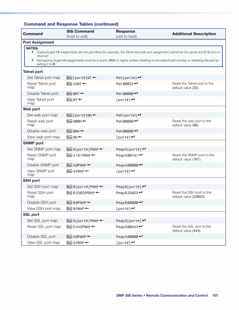
SMP 300 Series • Remote Communication and Control 107
CommandSIS Command(host to unit)
Response(unit to host)
Additional Description
Port AssignmentNOTES:
• Duplicate port# assignments are not permitted (for example, the Telnet and web port assignment cannot be the same) and E13 error is returned.
• Remapping of port# assignments must be to ports 1024 or higher (unless resetting to the default port number or disabling the port by setting it to 0).
Telnet portSet Telnet port map E [port#]MT } Pmt[port#]]
Reset Telnet port map
E 23MT } Pmt 00023 ] Reset the Telnet port to the default value (23).
Disable Telnet port E 0MT } Pmt 00000 ]
View Telnet port map
E MT } [port#]]
Web portSet web port map E [port#]MH } Pmh[port#]]
Reset web port map
E 80MH } Pmh 00080 ] Reset the web port to the default value (80).
Disable web port E 0MH } Pmh 00000 ]
View web port map E MH } [port#]]
SNMP portSet SNMP port map E A[port#]PMAP } Pmap A[port#]]
Reset SNMP port map
E A 161PMAP } Pmap A 00161 ] Reset the SNMP port to the default value (161).
Disable SNMP port E A 0PMAP } Pmap A 00000 ]
View SNMP port map
E A PMAP } [port#]]
SSH portSet SSH port map E B[port#]PMAP } Pmap B[port#]]
Reset SSH port map
E B 22023PMAP } Pmap B 22023 ] Reset the SSH port to the default value (22023).
Disable SSH port E B 0PMAP } Pmap B 00000 ]
View SSH port map E B PMAP } [port#]]
SSL portSet SSL port map E S[port#]PMAP } Pmap S[port#]]
Reset SSL port map E S 443PMAP } Pmap S 00443 ] Reset the SSL port to the default value (443).
Disable SSL port E S 0PMAP } Pmap S 00000 ]
View SSL port map E S PMAP } [port#]]
Command and Response Tables (continued)

SMP 300 Series • Remote Communication and Control 108
Command and Response Tables (continued)
CommandASCII Command(host to unit)
Response(unit to host)
Additional Description
SNMP (Simple Network Management Protocol)SNMP unit contact
Set unit contact E C X62! SNMP} SnmpC* X62!] Sets the unit contact to X62!.
Set unit contact to default
E C • SNMP} SnmpC*Not•Specified] Sets the unit contact to the default setting.
View unit contact E CSNMP} X62!] View the unit contact.
SNMP unit locationSet unit location E L X62@ SNMP} Snmp L* X62@] Sets the unit location to X62@.
Set unit location to default
E L•SNMP} SnmpL*Not•Specified] Sets the unit location to the default setting.
View unit location E LSNMP } X62@] View the unit location.
SNMP community stringsSet public community string
E P X62#SNMP} SnmpP* X62#] Sets public community string to X62#.
Set public community string to default
E P•SNMP} SnmpP*public] Sets community string to the default.
View public community string
E PSNMP} X62#] View the public community string.
Set private community string
E X X62$SNMP} SnmpX* X62$] Sets private community string to X62$.
Set private community string to default
E X•SNMP} SnmpX*private ] Sets private community string to the default setting.
View private community string
E XSNMP} X62$] View the private community string.
NOTE: Community strings are referred to as passwords in the web-based user interface.
SNMP access enableEnable SNMP access
E E1SNMP } SnmpE*1] Enable SNMP access.
Disable SNMP access
E E0SNMP } SnmpE*0] Disable SNMP access.
View SNMP state E ESNMP } X62) ] View the SNMP access setting.
NOTES: X62) = 0 = Off or disable (default), 1 = On or enable X62! = SNMP contact name text, up to 64 alphanumeric characters, hyphens, underscores and period (default = Not Specified). X62@ = SNMP location, up to 64 alphanumeric characters, hyphens, underscores and period. (default = Not Specified) X62# = SNMP public community string, up to 64 alphanumeric characters, hyphens, underscores and period. (default = public) X62$ = SNMP private community string, up to 64 alphanumeric characters, hyphens, underscores and period. (default = private)

SMP 300 Series • Remote Communication and Control 109
Command and Response Tables (continued)
CommandASCII Command(host to unit)
Response(unit to host)
Additional Description
IP Setup CommandsSet date / time E MM/DD/YY-
HH:MM:SS CT }Ipt • X1# ] Set the date and time.
View date / time E CT } X1# ] View the date and time.
Set time zoneExample:
E X1$ * TZON }E PST * TZON }
Tzon • X1$ * X1% ]Tzon • PST*(UTC-08:00/UTC-07:00)• a ifi i ]
View time zoneExample:
E TZON } X1$* X1% ]PST*(UTC-08:00/UTC-07:00) • a ifi i ]
Verbose mode 2/3 response adds Tzon • to beginning of string
View all time zones E * TZON } X1$* X1% ]... X1$* X1% ]]
Repeats for all time zones Verbose mode 2/3 adds Tzon • to beginning of string
Set DHCP on E 1DH } Idh1 ] Sets DHCP to on.
Set DHCP off E 0DH } Idh0 ] Sets DHCP to off.
View DHCP mode E DH } X( ] 0=DHCP off (default) 1=DHCP on.
Set IP address, subnet mask, gateway
E1*X1^*X1&*X1^ CISG} Cisg1*IP/subnet bits*gateway]
NOTE: The CISG command resets the network immediately without the need for a BOOT command.
View IP address, subnet mask, gateway
E 1CISG }Example:
IP/subnet bits*gateway ]192.168.254.254/16*0.0.0.0]
Set IP address E X1^ CI } Ipi • X1^ ]
View IP address E CI } X1^ ]
View hardware MAC address
E CH } X1* ] Iph • X1* ]
View the hardware MAC address of the unit. In verbose mode 2/3
Set subnet mask E X1& CS } Ips • X1& ]
View subnet mask E CS } X1& ]
Set gateway IP address
E X1^ CG } Ipg • X1^ ] Set the gateway IP address.
View gateway IP address
E CG } X1^ ] View the gateway IP address.
NOTES: X( = On/off 0 = Disabled/unassigned/off/unmuted (default), 1 = Enabled/assigned/on/muted X1# = Local date/time Set: MM/DD/YY-HH:MM:SS Read: day of week, date, month, year HH:MM:SS (for instance; Fri, 21 Jun 2002 10:54:00) X1$ = Time zone Acronym (2 to 6 letters) Example: PST for Pacific Standard Time X1% = Time zone offset GMT offset value (– 12:00 to 14:00) representing hours and minutes (HH:MM) local time is offset from GMT time and includes the time zone name. Example: PST*(UTC-08:00) Pacific Time X1^ = IP Address Default IP address: 192.168.254.254 Default Gateway: 0.0.0.0 Default DNS: 0.0.0.0 X1& = Subnet Mask Default: 255.255.0.0 X1* = Hardware MAC address 00-05-A6-xx-xx-xx

SMP 300 Series • Remote Communication and Control 110
Command and Response Tables (continued)
CommandASCII Command(host to unit)
Response(unit to host)
Additional Description
Set DNS server IP address
E X1^ DI } Ipd • X1^ ] Set the DNS server IP address (default: 0.0.0.0).
View DNS server IP address
E DI } X1^ ] View the DNS server IP address.
Set current port timeout
E 0 * X6( TC } Pti 0 * X6( ]
View current port timeout
E 0 TC } X6( ]
Set global IP port timeout
E 1* X6( TC} Pti1 * X6( ]
View global IP port timeout
E 1 TC} X6( ]
RS-232 PortConfigure serial port parameters
E1*X2%,X2^,X2&,X2* CP} Cpn 01•Ccp X2%, X2^, X2&, X2*]
Reset serial port E 1*9600,n,8,1CP } Cpn 01•Ccp X2%, X2^, X2&, X2*]
View serial port settings
E 1CP } X2%, X2^, X2&, X2* ]
Set serial port receive timeout
E1*X1(*X2)*X2@*X2! CE} Cpn01•CceX1(,X2),X2@,X2! ]
View serial port receive timeout
E 1CE } X1(,X2),X2@,X2! ]
NOTES: X1^ = IP Address Default IP address: 192.168.254.254 Default Gateway: 0.0.0.0 Default DNS: 0.0.0.0 X1( = Port timeout Time in tens of milliseconds to wait for characters coming into a serial port before terminating (min=0, max=32767, default: 10 = 100 ms). The response is returned with leading zeros. X2) = Intercharacter timeout Time in tens of milliseconds to wait between characters coming into a serial port before terminating (min=0, max=32767. Default: 2 = 20 ms). The response is returned with leading zeros. Commands using both X1( and X2) must have both values = 0 or both set to non-zero. X2! = Primary port status Parameter to set either the Length of message to receive, or the Delimiter value. L=#=byte count (min=0, max=32767. Default=0L=0 byte count). D = decimal value for ASCII character. (min=0, max=00255. Default=00000L). Value is placed prior to parameter: 3 byte length = “3L” and ASCII 0A delimiter is “10D”. The parameter is case sensitive, must use capital D or capital L. The response is returned with leading zeros. X2@ = Length delimiter Priority status for receiving timeouts: 0 = Use Send data string command parameters when available. 1 = Use Configure receive timeout command parameters (default = 0). X2% = RS-232 baud rate 9600 (default), 19200, 38400, 57600, 115200 bps X2^ = RS-232 parity Odd, Even, None (default), Mark, Space X2& = RS-232 data bits 7, 8 (default) X2* = RS-232 stop bits 1 (default), 2 X6( = Port timeout In tens of seconds, zero padded (default: 00030 = 300 seconds)

SMP 300 Series • Remote Communication and Control 111
Command and Response Tables (continued)
CommandASCII Command(host to unit)
Response(unit to host)
Additional Description
Password and Security Settings
Set administrator password
E X3#CA} Ipa• X3#] X3# = Up to 128 alpha-numeric characters
View administrator password
E CA} ****] If no password is set, the response is ] (no ****).
Reset (clear) administrator password
E •CA} Ipa•]
Set user password E X3#CU} Ipu• X3#] X3# = Up to 128 alpha-numeric characters.
View user password
E CU} ****] If no password is set, the response is ] (no ****).
Reset (clear) user password
E •CU} Ipu•]
View session security level
E CK} n ] Security level of connection 11 = User, 12 = Administrator
File CommandsChange directory E path/directory/CJ} Dirl path/directory/]
Return to root directory
E /CJ} Dirl/]
Up one directory E ../CJ} Dirl path/directory/]
View current directory
E CJ} path/directory/]
Erase current directory and included files
E /EF } Ddl] Also deletes files inside directory
Erase current directory and sub-directories
E //EF } Ddl]
List files from current directory and below
E LF } path/filename•date/time•length] path/filename•date/time•length] path/filename•date/time•length] ... space_remaining•Bytes Left]]
filename/date/time/bytes left
Input SelectionSelect input X50!* X50@! In X50!*X50@] Switches channel X50@ to input
X50!.
View selected input
X50@! X50!] View the input source X50! for channel X50@.
Set input 3 format 3* X50$\ Typ 03*X50$]
View input 3 format 3\ X50$]
Set input name E X50!,X51$ NI} Nmi X50!,X51$] Set the input source X50! name to X51$.
View input name E X50! NI} X51$]
View input selection/channel
32I ChA X50!*ChB X50!]
NOTES: X3# = Password Maximum length 12 characters. All alpha-numeric characters and ASCII symbols permitted except |, and ”space” X50! = Input number 1 to 5 X50@ = Output channel 1 = A (Input 1 and 2), 2 = B (Input 3, 4, and 5) X50$ = Input video format 1 to 3 X51$ = Input name Name (up to 16 characters) Default is "Input X" where "X" is the input number

SMP 300 Series • Remote Communication and Control 112
CommandASCII Command(host to unit)
Response(unit to host)
Additional Description
Input video aspect ratio Set to fill E X50!*1ASPR} Aspr X50!*01] Sets input X50! to fill.
Set to follow E X50!*2ASPR} Aspr X50!*02] Sets input X50! to follow.
Set to fit (zoom) E X50!*3ASPR} Aspr X50!*03] Sets input X50! to fit.
View aspect setting
E X50!ASPR} X4(]
Auto-Image and memoryEnable/disable Auto-Image per input
X50!*X(A Img X50!*X(]
View Auto-Image X50!*A X(]
Performs Auto-Image to current output
X50@ A Img X50@] Performs Auto-Image to the current input selection of output X50@.
Set Auto Memory on
E 1AMEM} Amem1]
Set Auto Memory off
E 0AMEM} Amem0]
View Auto Memory E AMEM} X(]
AudioView front panel audio level indicators
Example:
34I X58!*X58!] -58*-63 ]
left*rightVerbose 2/3 mode adds: Inf34*
RecordingStop recording E Y0 RCDR} RcdrY0 ]
Start recording E Y1 RCDR} RcdrY1 ]
Pause recording E Y2 RCDR} RcdrY2 ]
View record status E Y RCDR} X54)]
Extend record time E E X54! RCDR} RcdrE X54! ] For scheduled recordings only, extend by X54! minutes.
Add chapter marker
E B RCDR} RcdrB]
Execute swap % Tke] Swap channel A and channel B positions.
Recording status (secondary recording disabled)
I <ChA X50! * ChB X50!> * <X54^>*<free space in KBytes> * <time record> * <time remain>]
Recording status (secondary recording enabled)
I <ChA X50! * ChB X50!>*<X54^>*<internal*secondary destination> * <internal free space*external free space> * <time record>*<time remain_internal*time external>]
Command and Response Tables (continued)
NOTES: X( = On/off 0 = Disabled/unassigned/off/unmuted (default), 1 = Enabled/assigned/on/muted X4( = Aspect ratio See X4( on page 101 X50! = Input number 1 to 5 X50@ = Output channel 1 = A (Input 1 and 2), 2 = B (Input 3, 4, and 5) X54) = Recording status 0 = Stop, 1 = Record, 2 = Pause X54! = Time MM (0 to 60 minutes) X54^ = Recorder status stopped, usbfront, usbrear, usbrcp, N/A X58! = Front panel audio level left*right (see page 103)

SMP 300 Series • Remote Communication and Control 113
Command and Response Tables (continued)
CommandASCII Command(host to unit)
Response(unit to host)
Additional Description
View recording duration/elapsed time of recording
35I HH:MM:SS] Verbose 2/3 mode adds: Inf35*Displays 00:00:00 when not recording
View record time remaining (secondary recording disabled)
36I X54@ • HH:MM:SS] Verbose 2/3 mode adds: Inf36*00:00:00 when not recording
View record time remaining (secondary recording enabled)
36I internal •HH:MM:SS* X54@ •HH:MM:SS]
Verbose 2/3 mode: Inf36*HH:MM:SS00:00:00 when not recording
View record destination (secondary recording enabled)
37I internal * X54@ ] Verbose 2/3 mode adds: Inf37*
View record destination (secondary record disabled)
37I X54@ ]
Set record Destination
E D X56) RCDR} RcdrDX56) ] Select record destination for recording(s).
View record destination
E D RCDR} X54@] View recording destination for next recording,
Audio-only recordingEnable audio-only recording
E A1 * 1RCDR} RcdrA1 *1]
Disable audio-only recording
E A1 * 0RCDR} RcdrA1 *0 ]
View status E A1RCDR} X( ]
RCP 101 executive modeExecutive mode on 99 * 1X Exe99*1]
Executive mode off 99 * 0X Exe99 *0 ]
Query status 99 * X X( ]
SMP recording folder shared on SMDEnable folder share
E E1 * 1SHRF} ShrfE1*1] Allow SMP Recording folder share.
Disable folder share
E E1 * 0SHRF} ShrfE1 *0 ] Disable SMP Recording folder share.
Query folder share setting
E E1SHRF} X( ] View folder share status.
Query path E P1SHRF} <SMP IP>:/var/uf/recordings ] Shrfp1*<SMP IP>:/var/uf/recordings ]
View folder path. Verbose mode 2/3
NOTES: X( = On/off 0 = Disabled/unassigned/off/unmuted (default), 1 = Enabled/assigned/on/muted X54@ = Recording destination auto, internal, usbfront, usbrear, usbrcp, N/A X56) = Destination 0 = Auto, 1 = Internal, 2 = USBFront, 3 = USBRear, 11 = Internal + Auto 12 = Internal + USBFront, 13 = Internal + USBRear, 14 = Internal + USBRCP

SMP 300 Series • Remote Communication and Control 114
Command and Response Tables (continued)
CommandASCII Command(host to unit)
Response(unit to host)
Additional Description
Metadata commands (For composite mode only)Set output metadata
E M X53* * X53( RCDR} RcdrM X53* * X53( ]
Example: E M2*ProfessorXRCDR} RcdrM2*ProfessorX]
Query output metadata
E M X53* RCDR} X53( ]
Example: E M2 RCDR} ProfessorX]
PresetsUser presets
Recall user preset 1* X50@* X53). 1Rpr X50@* X53)] Set channel X50@ to preset number X53).
Save user preset 1* X50@* X53), 1Spr X50@* X53)]
Set user name E 1* X53) , X53! PNAM } Pnam1* X53) , X53!] Set preset number X53) to name X53!.
Query user name E 1* X53) PNAM } X53!]
Query user presets 52* X50! # X(1 X(2 X(3... X(16] PreU X50!* X(1 X(2 X(3... X(16]
Verbose mode 2/3
Input presetsRecall preset 2* X50!* X53@ . 2Rpr X50!* X53@]
Save preset 2* X50!* X53@ , 2Spr X50!* X53@]
Set preset name E 2* X53@ ,X53! PNAM } Pnam2* X53@ , X53!]
View preset name E 2* X53@ PNAM } X53!]
Delete input preset E X2* X53@ PRST } PrstX2*X53@]
Query input presets
51# X(1 X(2 X(3... X(128] PreIX(1 X(2 X(3... X(128]
Verbose mode 2/3.
Layout presets (for composite mode only)Save layout preset 7 * X53), 7Spr X53)] Save layout preset to X53).
Recall layout preset
7* X53). 7Rpr X53)] Recall layout preset X53)including input selections.
Recall layout preset
8* X53). 8Rpr X53)] Recall layout preset X53) without input selections.
Set preset name E 7* X53) ,X53! PNAM } Pnam7* X53) , X53!] Set X53) to X53!.
Query preset name E 7* X53) PNAM } X53!]
Reset layout preset to defaults
E X7 * X53) PRST } PrstX7* X53)] Reset X53) to defaults
NOTES: X( = On/off 0 = Disabled/unassigned/off/unmuted (default), 1 = Enabled/assigned/on/muted X50! = Input number 1 to 5 X50@ = Output channel 1 = Channel A, 2 = Channel B X53) = User/Encoder/Layout Preset Number 1 to 32 X53! = Preset Name Up to 16 characters X53@ = Input preset number 1 to 128 X53* = Metadata parameter 0 = Contributor, 1 = Coverage, 2 = Presenter, 3 = Date (view only), 4 = Description 5 = Format, 6 = Identifier (view only), 7 = Language, 8 = Publisher, 9 = Relation 10 = Rights, 11 = Source, 12 = Subject, 13 = Title, 14 = Type, 15 = SystemName 16 = Course X53( = Metadata value Up to 127 alpha-numeric characters. All metadata values are cleared to be ready for the next data cannot be updated once the recording starts. New metadata is applied to the next recording.

SMP 300 Series • Remote Communication and Control 115
NOTES: X50) = Streaming Encoder 1 = Archive Channel A, 2 = Archive Channel B (Available for Dual Channel only) 3 = Confidence Channel A X50% = Stream name Up to 16 characters X51$ = Encoder/Streaming preset name Up to 16 characters X53) = Streaming presets 1 to 32 (two digit response — 0 padding) X56# = Encoder presets 1 to 32
CommandASCII Command(host to unit)
Response(unit to host)
Additional Description
Recall layout preset (for confidence in Dual Channel mode only)Recall layout preset
9 * 3* X53). 9Rpr3 *X53)] Recall layout preset to X53) to confidence encoder in dual channel mode.
Encoder presetsRecall preset 4*X50) * X56# . 4Rpr X50) * X56#] Recalls Encoder preset X56# for
X50)
Save preset 4* X50) * X56# , 4Spr X50) * X56#] Saves Encoder preset X56# for selected channel
Set preset name E 4* X56# ,X51$ PNAM } Pnam4* X56# , X51$] Set encoder preset number X56# to name X51$.
View encoder preset name
E 4* X56# PNAM } X51$] View the name of Encoder preset X56#
Reset encoder preset to default
E X4* X56# PRST } PrstX4*X56#] Clears Encoder preset X56#, and sets Encoder preset name to [unassigned]
Stream nameSet stream name E N X50) * X50% STRC } StrcN X50) * X50%]
View stream name E N X50) STRC } X50%] StrcN X50) *X50%]
Verbose mode 2/3.
Streaming presetsRecall preset 3*X50) * X53) . 3Rpr X50) * X53)] Recalls Streaming preset X53)
for X50)
Save preset 3* X50) * X53) , 3Spr X50) * X53)] Saves Streaming preset X53) for selected channel
Set preset name E 3* X53) ,X51$ PNAM } Pnam3* X53) , X51$] Set encoder preset number X53) to name X51$.
View preset name E 3* X53) PNAM } X51$] View the name of Streaming preset X53)
Delete or clear preset
E X3* X53) PRST } PrstX3*X53)] Clears preset X53), and sets Streaming preset name to [unassigned]

SMP 300 Series • Remote Communication and Control 116
CommandASCII Command(host to unit)
Response(unit to host)
Additional Description
Input adjustments (Input 3 only)Pixel phase
Set pixel phase E 3*X60# PHAS} Phas03*X60#] Set input 3 to pixel phase X60#
Increment pixel phase value
E 3+PHAS} Phas03*X60#] Increment pixel phase of input 3
Decrement pixel phase value
E 3-PHAS} Phas03*X60#] Decrement pixel phase of input 3
View value E 3 PHAS} X60#] View pixel phase X60# of input 3
Total pixelsSet total pixels value
E 3*X60% TPIX} Tpix 03*X60%] Set total pixels (per line) for input 3 to X60%.
Increment total pixels value
E 3+TPIX} Tpix 03*X60%] Increment the total pixels X60% for input 3 by one pixel.
Decrement total pixels value
E 3-TPIX} Tpix 03*X60%] Decrement the total pixels X60% for input 3 by one pixel.
View total pixels E 3 TPIX} X60%] View total pixels for input 3.
Horizontal startSet horizontal start E 3*X60$ HSRT} Hsrt 03*X60$] Set the horizontal start value for
input 3 to X60$.
Increment horizontal start
E 3+HSRT} Hsrt 03*X60$] Increment the horizontal start value X60$ for input 3 by one pixel.
Decrement horizontal start
E 3-HSRT} Hsrt 03*X60$] Decrement the horizontal start value X60$ for input 3 by one pixel.
View horizontal start
E 3 HSRT} X60$] View the horizontal start value X60$ of input 3.
Vertical startSet vertical start E 3*X60$ VSRT} Vsrt 03*X60$] Set the vertical start value of
input 3 to X60$.
Increment vertical start value
E 3+VSRT} Vsrt 03*X60$] Increment the vertical start value X60$ for input 3 by one pixel.
Decrement vertical start value
E 3-VSRT} Vsrt 03*X60$] Decrement the vertical start value X60$ for input 3 by one pixel.
View vertical start E 3 VSRT} X60$] View the vertical start value X60$ of input 3.
Command and Response Tables (continued)
NOTES: X60# = Pixel phase 0 to 63 (default: 32) X60% = Total pixels Up to +512 of the default value for the detected range X60$ = Horizontal and vertical start 0 to 255 (default: 128)

SMP 300 Series • Remote Communication and Control 117
Command and Response Tables (continued)
CommandASCII Command(host to unit)
Response(unit to host)
Additional Description
Active pixelsSet active pixels E 3*X60& APIX} Apix03*X60&] Set the active pixels per line for
input 3 to X60&.
Increment active pixels
E 3+APIX} Apix03*X60&] Increment the active pixels X60& for input 3 by one pixel.
Decrement active pixels
E 3-APIX} Apix03*X60&] Decrement the active pixels X60& for input 3 by one pixel.
View active pixels E 3 APIX} X60&] View the active pixels value X60& of input 3.
Active linesSet active lines E 3*X60^ ALIN} Alin03*X60^] Set active lines for input 3 to
X60^.
Increment active lines
E 3+ALIN} Alin03*X60^] Increment the active lines X60^ for input 3 by one pixel.
Decrement active lines
E 3-ALIN} Alin03*X60^] Decrement the active lines X60^ for input 3 by one pixel.
View active lines E 3 ALIN} X60^] View the active lines value X60^ of input 3.
Picture adjustmentsColor (NTSC and PAL inputs only)
Specify a value E X50@ *X60*COLR } Colr X50@ *X60*] Sets color level to X60*.
Increment value E X50@ + COLR } Colr X50@*X60* ] Increments color level.
Decrement value E X50@ C } Colr X50@*X60* ] Decrements color level.
View E X50@ COLR } X60* ] View current setting.
Tint (NTSC input only)Specify a value E X50@ *X60* TINT } Tint X50@ *X60* ] Sets tint level to X60*.
Increment value E X50@ + TINT } Tint X50@ *X60* ] Increments tint level.
Decrement value E X50@ } Tint X50@ *X60* ] Decrements tint level.
View E X50@ TINT } X60* ] View current setting.
ContrastSpecify a value E X50@ *X60* CONT } Cont X50@ *X60* ] Sets contrast level to X60*.
Increment value E X50@ + CONT } Cont X50@ *X60* ] Increments contrast level.
Decrement value E X50@ C } Cont X50@ *X60* ] Decrements contrast level.
View E X50@ CONT } X60* ] View current setting.
BrightnessSpecify a value E X50@ *X60* BRIT } Brit X50@ *X60* ] Sets brightness level X60*.
Increment value E X50@ + BRIT } Brit X50@ *X60* ] Increments brightness level.
Decrement value E X50@ } Brit X50@ *X60*] Decrements brightness level.
View E X50@ BRIT } X60* ] View current setting.
NOTES: X50@ = Output channel 01 = A, 02 = B X60^ = Active lines Up to +256 of the default value for the detected resolution X60& = Active pixels Up to +512 of the default value for the detected resolution X60* = Picture adjust 000 to 127, default: 064 (3-digit response)
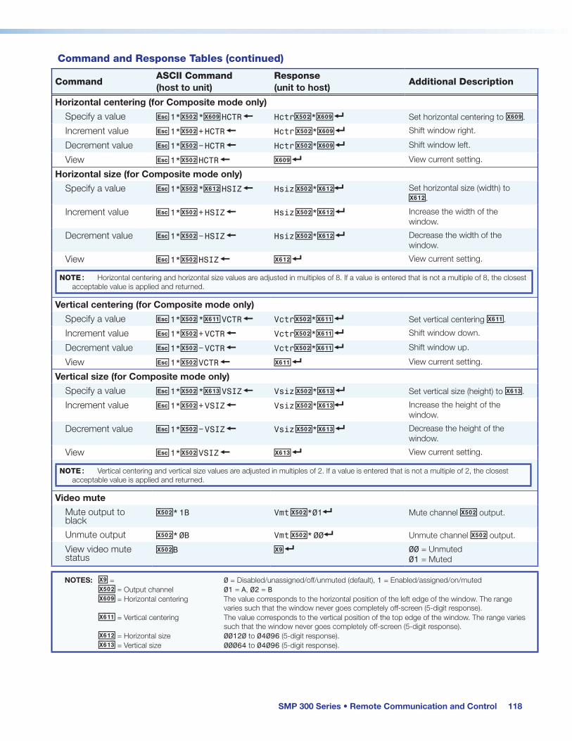
SMP 300 Series • Remote Communication and Control 118
CommandASCII Command(host to unit)
Response(unit to host)
Additional Description
Horizontal centering (for Composite mode only)Specify a value E 1*X50@ *X60( HCTR } HctrX50@*X60( ] Set horizontal centering to X60(.
Increment value E 1*X50@ + HCTR } Hctr X50@*X60( ] Shift window right.
Decrement value E 1*X50@ C } Hctr X50@*X60( ] Shift window left.
View E 1*X50@ HCTR } X60( ] View current setting.
Horizontal size (for Composite mode only)Specify a value E 1*X50@ *X61@ HSIZ } Hsiz X50@*X61@] Set horizontal size (width) to
X61@.
Increment value E 1*X50@ + HSIZ } Hsiz X50@*X61@ ] Increase the width of the window.
Decrement value E 1*X50@ } Hsiz X50@*X61@ ] Decrease the width of the window.
View E 1*X50@ HSIZ } X61@ ] View current setting.
NOTE: Horizontal centering and horizontal size values are adjusted in multiples of 8. If a value is entered that is not a multiple of 8, the closest acceptable value is applied and returned.
Vertical centering (for Composite mode only)Specify a value E 1*X50@ *X61! VCTR } VctrX50@*X61! ] Set vertical centering X61!.
Increment value E 1*X50@ + VCTR } VctrX50@*X61! ] Shift window down.
Decrement value E 1*X50@ C } VctrX50@*X61! ] Shift window up.
View E 1*X50@ VCTR } X61! ] View current setting.
Vertical size (for Composite mode only)Specify a value E 1*X50@ *X61# VSIZ } Vsiz X50@*X61# ] Set vertical size (height) to X61#.
Increment value E 1*X50@ + VSIZ } Vsiz X50@*X61#] Increase the height of the window.
Decrement value E 1*X50@ } Vsiz X50@*X61# ] Decrease the height of the window.
View E 1*X50@ VSIZ } X61# ] View current setting.
NOTE: Vertical centering and vertical size values are adjusted in multiples of 2. If a value is entered that is not a multiple of 2, the closest acceptable value is applied and returned.
Video muteMute output to black
X50@* 1B Vmt X50@*01] Mute channel X50@ output.
Unmute output X50@* 0B Vmt X50@* 00] Unmute channel X50@ output.
View video mute status
X50@B X( ] 00 = Unmuted 01 = Muted
Command and Response Tables (continued)
NOTES: X( = 0 = Disabled/unassigned/off/unmuted (default), 1 = Enabled/assigned/on/muted X50@ = Output channel 01 = A, 02 = B X60( = Horizontal centering The value corresponds to the horizontal position of the left edge of the window. The range varies such that the window never goes completely off-screen (5-digit response). X61! = Vertical centering The value corresponds to the vertical position of the top edge of the window. The range varies such that the window never goes completely off-screen (5-digit response). X61@ = Horizontal size 00120 to 04096 (5-digit response). X61# = Vertical size 00064 to 04096 (5-digit response).

SMP 300 Series • Remote Communication and Control 119
CommandASCII Command(host to unit)
Response(unit to host)
Additional Description
Encoder Settings (Archive Encode and Recording)Stream enable/disable
Stream enable E X50)*X( STRC } StrcX50)*X(] Enable or disable each stream.
View stream status E X50)STRC } X(]
RTMP (primary) destination URLSet RTMP URL EU1*X50)*X56^RTMP} RtmpU1*X50)*X56^] Enter primary publish URL X50).
View RTMP URL EU1*X50)RTMP} X56^] View primary publish URL X50).
RTMP (backup) destination URLSet RTMP URL EU2*X50)*X56^RTMP} RtmpU2*X50)*X56^] Enter backup publish URL X50).
View RTMP URL EU2*X50)RTMP} X56^] View backup publish URL X50).
RTMP stream enable/disableEnable RTMP push stream
EEX50)*X(RTMP} RtmpEX50)*X(] Enable or disable RTMP push stream X50).
View RTMP push stream
EEX50)RTMP} X(] View status of RTMP push stream X50).
RTMP stream statusQuery primary RTMP Status
E S1*X50) RTMP} X*] RtmpS1*X50) *X*]
Sync with schedule (return error code if scheduling is off or not supported). Verbose mode 2/3.
Query backup RTMP Status
E S2*X50) RTMP} X*] RtmpS2*X50) *X*]
Schedule is refreshed. Verbose mode 2/3.
Enable/disable single/secondary recording (Composite mode)Single recording enable
E X1*1RCDR } Rcdr X1*1] Enable single recording (internal or external).
Secondary recording enable
E X1*2RCDR } Rcdr X1*2] Enable secondary recording (internal or external).
Recording disable E X1*0 RCDR } Rcdr X1*0] Disable recording.
View record status E X1RCDR } X58@ ] View status.
Enable/disable archive recording (Dual Channel mode)Set archive channel A
E X1* X(RCDR } Rcdr X1*X(] Set archive channel A.
View channel A record status
E X1RCDR } X(] View channel A record status.
Set archive channel B
E X2* X(RCDR } Rcdr X2*X(] Set archive channel B.
View ch B record status
E X2RCDR } X(] View channel B record status.
Command and Response Tables (continued)
NOTES: X* = Status 0 = Offline; 1 = Live X( = 0 = Disabled/unassigned/off/unmuted (default), 1 = Enabled/assigned/on/muted X50) = Stream selection 1 = Archive Channlel A, 2 = Archive Channel B (Available for Dual Channel mode only) 3 = Confidence Channel A X56^ = RTMP URL (string) X58@ = Recording mode 0 = Channel A disabled, 1 = Single Recording in Composite mode 2 = Internal + Secondary Recording in Composite mode

SMP 300 Series • Remote Communication and Control 120
CommandASCII Command(host to unit)
Response(unit to host)
Additional Description
Encoder profileSet profile E X50)* X4) EPRO } EproX50)* X4) ] Set encode profile to X4).
View profile E X50) EPRO } X4) ] View encode profile X4).
Set output mode E1*X4! SMOD } Smod1* X4! ] Set output mode to X4!.
View output mode E1 SMOD } X4!] View output mode X4!.
Composite/Dual Channel encoder modeSet archive encoding mode
E 1* X50# ENCM } Encm 1*X50#] Select encoding mode for Archive.
View selected encoding mode
E 1ENCM } X50#] View encoding mode for Archive.
HDMI video muteEnable blanking 99* 1B Vmt99*1] Blanks HDMI video output.
Disable blanking 99* 0B Vmt99*0 ] Displays HDMI video output.
View status 99B X( ] View the video mute status.
HDMI audio muteMute HDMI audio 99* 1Z Amt99*1] Mute HDMI audio output.
Unmute HDMI audio
99* 0Z Amt99*0 ] Unmute HDMI audio output.
View status 99Z X( ] View the audio mute status.
Dual Channel HDMI outputSet HDMI output E X6$ OMOD } Omod X6$] Set HDMI output to X6$.
Query HDMI output E OMOD } X6$ ]
Bit rate controlSet bit rate control type
E X50)* X4@ BRCT } BrctX50)* X4@ ] Set bit rate control type to X4@.
View bit rate control type
E X50)BRCT } X4@ ]
Video bit rateSet video bit rate E VX50)* X4# BITR } BitrVX50)* X4# ] Set video bit rate to X4#.
View video bit rate E VX50)BITR } X4# ]
Audio bit rateSet audio bit rate E AX50)* X4$ BITR } BitrAX50)* X4$ ] Set audio bit rate to X4$.
View audio bit rate E AX50)BITR } X4$ ]
Command and Response Tables (continued)
NOTES: X( = On/Off 0 = Disabled/unassigned/off/unmuted (default), 1 = Enabled/assigned/on/muted X4) = Encode profile 1 = Base, 2 = Main, 3 = High X4! = Output mode 1 = Video and audio, 2 = Video only X4@ = Bit rate control type 0 = VBR, 1 = CVBR, 2 = CBR X4# = Video bit rate 00200 to 10000 (5-digit response) X4$ = Audio bit rate 80, 96, 128, 192, 256, 320 X6$ = HDMI output 0 = ChA full screen, 1 = ChB full screen, 2 = Confidence layout X50) = Stream selection 1 = Archive Channel A, 2 = Archive Channel B (Available for Dual Channel mode only) 3 = Confidence Channel A X50# = Encoding mode 0 = Composite mode, 1 = Dual Channel mode

SMP 300 Series • Remote Communication and Control 121
CommandASCII Command(host to unit)
Response(unit to host)
Additional Description
Group of pictures (GOP) lengthSet GOP length E X50)* X4% GOPL } Gopl X50)* X4% ] Set GOP length to X4%.
View GOP length E X50) GOPL } X4% ]
Record resolution and frame rateSet record resolution
E X50)* X4^ VRES } Vres X50)* X4^ ]
View record resolution
E X50) VRES } X4^ ]
Set record frame rate
E X50)* X4& VFRM } Vfrm X50)* X4& ]
View record frame rate
E X50) VFRM } X4& ]
View record resolution and frame rate (For composite mode only)
33I Horz resolution x Vert resolution*Frame rate ]Example: 1280x 720*30 ]
View current recording information (For composite mode only)
1*I <ChA X50@*ChB X50!>*<X4^>* <X4&>*<X54#>*<X4#>]
Verbose mode 2/3 adds Inf*.
Recording thumbnail sizeSet thumbnail size E T X54% RCDR } RcdrT X54% ]
View recording thumbnail size
E TRCDR } X54% ]
Preview output refresh rateSet preview output refresh rate
E X4* RATE } Rate X4* ]
View output refresh rate
E RATE } X4* ]
Command and Response Tables (continued)
NOTES: X4# = Video bit rate 00200 to 10000 (5-digit response) X4% = GOP length 1 to 30 X4^ = Record resolution 480p, 720p, 1080p, 512x288, 1024x768, 1280x1024, Custom X4& = Record frame rate 1 = 30, 2 = 25, 3 = 24, 4 = 15, 5 = 12.5, 6 = 12, 7 = 10, 8 = 5 X4* = Output refresh rate 1 = 60 Hz (default), 2 = 50 Hz X50) = Stream selection 1 = Archive Channel A, 2 = Archive Channel B (Available for Dual Channel mode only) 3 = Confidence Channel A X50! = Input number 1 to 5 X50@ = Output channel 1 = A, 2 = B X54# = File size File size in MB X54% = Thumbnail size 0 = Normal (default), 1 = Follows archive resolution

SMP 300 Series • Remote Communication and Control 122
CommandASCII Command(host to unit)
Response(unit to host)
Additional Description
Advanced ConfigurationOverscan mode
Set overscan mode
E X50$* X51) OSCN} Oscn X50$* X51)] Sets input type X50$ to overscan mode X51).
View overscan mode
E X50$ OSCN} X51)] View the current overscan X51) for input type X50$.
Test patternSet test pattern E X56% TEST} TestX56%]
View test pattern E TEST} X56%]
HDCP settings (HDMI Inputs only)View input HDCP status
EI X50! HDCP} X51!]
Set input HDCP authorization on
EE1* X50! HDCP} HdcpE X50!*1] Turn HDCP authorized device on for input X50!
Set input HDCP authorization off
EE0* X50! HDCP} HdcpE X50!*0] Turn HDCP authorized device off for input X50! (default)
View input HDCP authorization
EE X50! HDCP} X(]
Enable HDCP notification
EN1HDCP} HdcpN1] Enable green screen HDCP notification (default)
Disable HDCP notification
EN0HDCP} HdcpN0] Disable green screen HDCP notification
View HDCP notification
ENHDCP} X51@]
Background image (for composite mode only)Select background filename
E filenameRF} Imr filename]
View background filename
E RF} "filename"]
Mute background image
E 0RF} Imr0]
Command and Response Tables (continued)
NOTES: X( = On/off 0 = Disabled/unassigned/off/unmuted (default), 1 = Enabled/assigned/on/muted X50! = Input number 1 to 5 X50$ = Input video format 1 = YUVp/HDTV (default), 2 = YUVi, 3 = Composite X51) = Overscan 0 = 0% (default: HDMI inputs), 1 = 2.5% (default: YUVp input) 3 = 5.0% (default: YUVi and composite inputs) X51! = HDCP status 0 = No sink/source detected, 1 = HDCP detected, 2 = Sink/source detected but no HDCP X51@ = HDCP notification 0 = Off (mute output to black), 1 = On (green HDCP notification-screen, default) X56% = Test patterns 0 = Off (default), 1 = Color bars, 2 = Aspect ratio 1.33, 3 = Aspect ratio 1.78, 4 = Aspect ratio 1.85, 5 = Crop, 6 = Pulse, 7 = Timestamp (For composite mode only) 8 = Universal OSD (For composite mode only)

SMP 300 Series • Remote Communication and Control 123
Command and Response Tables (continued)
CommandASCII Command(host to unit)
Response(unit to host)
Additional Description
AudioAudio input format
Set audio format E I X!* X3) AFMT } Afmt X!* X3) ]
View E I X! AFMT } X3) ]
Audio delay NOTE: Set the audio delay to zero to disable it.
Set audio delay E 1* X56$ ADLY } Adly1* X56$ ]
View E 1 ADLY } X56$ ] View audio delay value.
Audio muteMute audio channel
E M X50^*1AU} DsM X50^*1] Mute audio channel X50^.
Unmute audio channel
E M X50^*0AU} DsM X50^*0] Unmute audio channel X50^.
View audio channel mute status
E M X50^ AU} X(] 0 = Off (unmuted) 1 = On (muted)
NOTE: The audio output mute setting applies to the stream, recording, and.
Audio levelSet input audio level
E G X50^*X50& AU} DsG X50^* X50&] Set audio input channel X50^ to level X50&.
Example: E G 40000*100AU} DsG40000*100] Set analog audio input A (left) to +10 dB
View input audio level
E G X50^ AU} X50&] View input audio channel X50^ level X50&.
Example: E G 40000AU} 100] Analog audio input A (left) is set to +10 dB
NOTES: X! = Audio input 1 to 4, 1 to 5 for SDI models X( = 0 = Disabled/unassigned/off/unmuted (default), 1 = Enabled/assigned/on/muted X3) = Audio format 0 = Disable audio, 1 = Analog (default for input 3), 2 = PLCM 2 CH (default) X50^ = Audio selection 40000 = Analog Input A (Left), 40001 = Analog Input A (Right), 40002 = Digital input A (Left) 40003 = Digital input A (Right), 40004 = Analog Input B (Left), 40005 = Analog Input B (Right) 40006 = Digital input B (Left), 40007 = Digital input B (Right), 60000 = Output (Left, for audio mute control only), 60001 = Output (Right, for audio mute control only) X50& = Audio level Audio level in 0.1 dB steps (-180 to 240 = -18.0 to +24.0 dB) X56$ = Audio delay 000 to 999 ms (default 0 ms, 3-digit response)

SMP 300 Series • Remote Communication and Control 124
CommandASCII Command(host to unit)
Response(unit to host)
Additional Description
Safely eject USB storageEject USB storage E X59!USBE} USBE X59!]
Delete recording event and files by DB_IDDelete recording event and file
E Z X59@RCDR} RcdrZ X59@]
EDID MinderAssign EDID to specific input
E A X50!*X6* EDID } EdidA X50!*X6* ] X50! = Video inputs 1, 2, and 4 X6* = See Table 1. EDID Values on the next page
View EDID assignment
E A X50! EDID } X6* ]
Import EDID to user location
E I X6&, fi naEDID}
EdidI X6&] Import a 128 or 256-Byte binary EDID file to the user loaded EDID location [1 to 3].
Export EDID in binary format
E E X6* fi naEDID}
EdidEX6* ] Export a 128 or 256-Byte binary EDID file from EDID location X6*. [filename] can optionally carry a full path name. The EDID file is a .bin file, carrying 128 or 256 bytes of binary data.
NOTES: X( = 0 = Disabled/unassigned/off/unmuted (default), 1 = Enabled/assigned/on/muted X6& = EDID User loaded slots 1, 2, and 3 X6* = EDID number See Table 1. EDID Values on the next page X50! = Input number 1 to 5 X50^ = Audio selection 40000 = Analog Input A (Left), 40001 = Analog Input A (Right), 40002 = Digital input A (Left) 40003 = Digital input A (Right), 40004 = Analog Input B (Left), 40005 = Analog Input B (Right) 40006 = Digital input B (Left), 40007 = Digital input B (Right), 60000 = Output (Left, for audio mute control only), 60001 = Output (Right, for audio mute control only) X50& = Audio level Audio level in 0.1 dB steps (-180 to 240 = -18.0 to +24.0 dB) X59! = Eject USB storage 0 = All USB storage, 2 = USBFront, 3 = USBRear, 4 = USBRCP X59@ = Delete recording by DB_ID Valid DB_ID number (integer)

SMP 300 Series • Remote Communication and Control 125
Table 1. EDID Values
X6* Resolution Refresh Rate Type Video Format Audio
1 800 x 600 60 Hz PC DVI N/A
2 1024 x 768 60 Hz PC DVI N/A
3 1280 x 720 60 Hz PC DVI N/A
4 1280 x 768 60 Hz PC DVI N/A
5 1280 x 800 60 Hz PC DVI N/A
6 1280 x 1024 60 Hz PC DVI N/A
7 1360 x 768 60 Hz PC DVI N/A
8 1366 x 768 60 Hz PC DVI N/A
9 1400 x 1050 60 Hz PC DVI N/A
10 1440 x 900 60 Hz PC DVI N/A
11 1600 x 900 60 Hz PC DVI N/A
12 1600 x 1200 60 Hz PC DVI N/A
13 1680 x 1050 60 Hz PC DVI N/A
14 1920 x 1080 60 Hz PC DVI N/A
15 1920 x 1200 60 Hz PC DVI N/A
16 800 x 600 60 Hz PC HDMI 2-Ch
17 1024 x 768 60 Hz PC HDMI 2-Ch
18 1280 x 768 60 Hz PC HDMI 2-Ch
19 1280 x 800 60 Hz PC HDMI 2-Ch
20 1280 x 1024 60 Hz PC HDMI 2-Ch
21 1360 x 768 60 Hz PC HDMI 2-Ch
22 1366 x 768 60 Hz PC HDMI 2-Ch
23 1400 x 1050 60 Hz PC HDMI 2-Ch
24 1440 x 900 60 Hz PC HDMI 2-Ch
25 1600 x 900 60 Hz PC HDMI 2-Ch
26 1600 x 1200 60 Hz PC HDMI 2-Ch
27 1680 x 1050 60 Hz PC HDMI 2-Ch
28 1920 x 1200 60 Hz PC HDMI 2-Ch
29 480p 60 Hz HDTV HDMI 2-Ch
30 576p 50 Hz HDTV HDMI 2-Ch
31 720p 50 Hz HDTV HDMI 2-Ch
32* 720p 60 Hz HDTV HDMI 2-Ch
33 1080i 50 Hz HDTV HDMI 2-Ch
34 1080i 60 Hz HDTV HDMI 2-Ch
35 1080p 25 Hz HDTV HDMI 2-Ch
36 1080p 50 Hz HDTV HDMI 2-Ch
37 1080p 24 Hz HDTV HDMI 2-Ch
38 1080p 60 Hz HDTV HDMI 2-Ch
39 User Loaded Slot 1
40 User Loaded Slot 2
41 User Loaded Slot 3 * Default