remote office 911x series - smoe.orgdocs.smoe.org/nortel/€¦ · remote office 911x series...
TRANSCRIPT

Remote Office 911x Series Installation and Administration Guide
Product release 1.3 Standard 1.1 October 2001
555-8421-220


Remote Office 911x SeriesInstallation and Administration Guide
Product release: 1.3Publication number: 555-8421-220Document release: Standard 1.1Date: October 2001
Copyright © 2001 Nortel Networks, All Rights Reserved.
Printed in Canada.
All information contained in this document is subject to change without notice. Nortel Networks reserves the right to make changes to equipment design or program components, as progress in engineering, manufacturing methods, or other circumstances may warrant.
*Nortel Networks, the Nortel Networks logo, the Globemark, and Unified Networks, Meridian 1, MSL-100, and Succession Communication Server for Enterprise 1000 are trademarks of Nortel Networks.
MICROSOFT, MS-DOS, WINDOWS, and WINDOWS NT are trademarks of Microsoft Corporation.


October 2001 Publication history
Publication history
October 2001 This is the Standard 1.1 issue of the Remote Office 911x Series Installation and Administration Guide (NTP 555-8421-220). This document provides product descriptions, planning, installation, configuration, administration, and troubleshooting information for the Remote Office Product release 1.3 of the Remote Office 911x series unit.
Remote Office 911x Series Installation and Administration Guide v

Publication history Standard 1.1
vi Remote Office 911x Series Installation and Administration Guide

Contents
About this document xvAbout this guide . . . . . . . . . . . . . . . . . . . . . . . . . . . . . . . . . . . . . . . . . . . . . . . xvi
How to use this guide . . . . . . . . . . . . . . . . . . . . . . . . . . . . . . . . . . . . . . xviProduct overview . . . . . . . . . . . . . . . . . . . . . . . . . . . . . . . . . . . . . . . . . . . . . xviiSkills you need . . . . . . . . . . . . . . . . . . . . . . . . . . . . . . . . . . . . . . . . . . . . . . . xviii
Nortel Networks product knowledge . . . . . . . . . . . . . . . . . . . . . . . . . xviiiTelecommunications knowledge. . . . . . . . . . . . . . . . . . . . . . . . . . . . . xviiiData networking knowledge. . . . . . . . . . . . . . . . . . . . . . . . . . . . . . . . . xix
Conventions used in this guide . . . . . . . . . . . . . . . . . . . . . . . . . . . . . . . . . . . . xxPrecautionary messages. . . . . . . . . . . . . . . . . . . . . . . . . . . . . . . . . . . . xxInstructions for selecting menu options . . . . . . . . . . . . . . . . . . . . . . . . xxInstructions for displaying property sheets . . . . . . . . . . . . . . . . . . . . . xxPBX terminology . . . . . . . . . . . . . . . . . . . . . . . . . . . . . . . . . . . . . . . . . xxi
Related information products . . . . . . . . . . . . . . . . . . . . . . . . . . . . . . . . . . . . xxiiPrinted documents . . . . . . . . . . . . . . . . . . . . . . . . . . . . . . . . . . . . . . . xxiiCD-ROM . . . . . . . . . . . . . . . . . . . . . . . . . . . . . . . . . . . . . . . . . . . . . . xxiii
1 Remote Office 911x series description 1Product Introduction . . . . . . . . . . . . . . . . . . . . . . . . . . . . . . . . . . . . . . . . . . . . . 2
Remote Office 9110 circuit card. . . . . . . . . . . . . . . . . . . . . . . . . . . . . . . 2Remote Office 9115 unit . . . . . . . . . . . . . . . . . . . . . . . . . . . . . . . . . . . . . 3Reach Line Card . . . . . . . . . . . . . . . . . . . . . . . . . . . . . . . . . . . . . . . . . . 3Voice over IP technology . . . . . . . . . . . . . . . . . . . . . . . . . . . . . . . . . . . . 3Configuration - Device and Software . . . . . . . . . . . . . . . . . . . . . . . . . . 4
Hardware description . . . . . . . . . . . . . . . . . . . . . . . . . . . . . . . . . . . . . . . . . . . . 5Remote Office 911x series unit LEDs. . . . . . . . . . . . . . . . . . . . . . . . . . . 5Remote Office 911x series unit LED display diagrams . . . . . . . . . . . . . 6Remote Office 9110 circuit card. . . . . . . . . . . . . . . . . . . . . . . . . . . . . . . 7Remote Office 9115 unit . . . . . . . . . . . . . . . . . . . . . . . . . . . . . . . . . . . . . 7Universal power supply support - Remote Office 9110 circuit card . . . 8Universal power supply support - Remote Office 9115 unit . . . . . . . . . 9Internet Access Device description . . . . . . . . . . . . . . . . . . . . . . . . . . . 10
Remote Office 911x Series Installation and Administration Guide vii

Contents Standard 1.1
Connection options . . . . . . . . . . . . . . . . . . . . . . . . . . . . . . . . . . . . . . . . . . . . . 1110BaseT Ethernet interface . . . . . . . . . . . . . . . . . . . . . . . . . . . . . . . . . 11PSTN connection . . . . . . . . . . . . . . . . . . . . . . . . . . . . . . . . . . . . . . . . . 11Quality of Service Transitioning Technology. . . . . . . . . . . . . . . . . . . . 11
How Remote Office 911x series units work. . . . . . . . . . . . . . . . . . . . . . . . . . 12Outgoing call process . . . . . . . . . . . . . . . . . . . . . . . . . . . . . . . . . . . . . 13Incoming call process . . . . . . . . . . . . . . . . . . . . . . . . . . . . . . . . . . . . . 13Host-controlled call mode . . . . . . . . . . . . . . . . . . . . . . . . . . . . . . . . . . 13Locally controlled call mode . . . . . . . . . . . . . . . . . . . . . . . . . . . . . . . . 13Quality of Service Transitioning Technology. . . . . . . . . . . . . . . . . . . . 14Call scenario 1: host-controlled—corporate internal call . . . . . . . . . 15Call scenario 2: host-controlled—corporate external call . . . . . . . . . 17Call scenario 3: locally controlled mode—local call . . . . . . . . . . . . . 19
System security . . . . . . . . . . . . . . . . . . . . . . . . . . . . . . . . . . . . . . . . . . . . . . . . 21No security . . . . . . . . . . . . . . . . . . . . . . . . . . . . . . . . . . . . . . . . . . . . . . 21Security identifier. . . . . . . . . . . . . . . . . . . . . . . . . . . . . . . . . . . . . . . . . 21
Telephones . . . . . . . . . . . . . . . . . . . . . . . . . . . . . . . . . . . . . . . . . . . . . . . . . . . 22Supported digital telephones . . . . . . . . . . . . . . . . . . . . . . . . . . . . . . . . 22Required footstand for Remote Office 9110 units . . . . . . . . . . . . . . . . 22Supported telephone modules . . . . . . . . . . . . . . . . . . . . . . . . . . . . . . . 22Supported telephone features. . . . . . . . . . . . . . . . . . . . . . . . . . . . . . . . 23Computer telephony integration applications . . . . . . . . . . . . . . . . . . . 23Automatic Call Distribution (ACD) applications . . . . . . . . . . . . . . . . 24
Voice over IP . . . . . . . . . . . . . . . . . . . . . . . . . . . . . . . . . . . . . . . . . . . . . . . . . 25How QoS transitioning technology works . . . . . . . . . . . . . . . . . . . . . . 25
Call timers (permanent and call on demand) . . . . . . . . . . . . . . . . . . . . . . . . . 26Minimum call duration timer . . . . . . . . . . . . . . . . . . . . . . . . . . . . . . . . 26Idle timer . . . . . . . . . . . . . . . . . . . . . . . . . . . . . . . . . . . . . . . . . . . . . . . 26How the timers work to control PSTN costs . . . . . . . . . . . . . . . . . . . . 27
Local calling . . . . . . . . . . . . . . . . . . . . . . . . . . . . . . . . . . . . . . . . . . . . . . . . . . 28Local calls through PSTN . . . . . . . . . . . . . . . . . . . . . . . . . . . . . . . . . . 28Supported telephone features. . . . . . . . . . . . . . . . . . . . . . . . . . . . . . . . 28
Online/Offline Table. . . . . . . . . . . . . . . . . . . . . . . . . . . . . . . . . . . . . . . . . . . . 29Emergency service number. . . . . . . . . . . . . . . . . . . . . . . . . . . . . . . . . . . . . . . 30Configuration Manager. . . . . . . . . . . . . . . . . . . . . . . . . . . . . . . . . . . . . . . . . . 31Power requirements . . . . . . . . . . . . . . . . . . . . . . . . . . . . . . . . . . . . . . . . . . . . 32
Input specifications . . . . . . . . . . . . . . . . . . . . . . . . . . . . . . . . . . . . . . . 32Output specifications . . . . . . . . . . . . . . . . . . . . . . . . . . . . . . . . . . . . . . 32
viii Remote Office 911x Series Installation and Administration Guide

October 2001 Contents
2 Planning for installation 33Physical environment . . . . . . . . . . . . . . . . . . . . . . . . . . . . . . . . . . . . . . . . . . . 34
Space . . . . . . . . . . . . . . . . . . . . . . . . . . . . . . . . . . . . . . . . . . . . . . . . . . 34Temperature . . . . . . . . . . . . . . . . . . . . . . . . . . . . . . . . . . . . . . . . . . . . . 34Mounting options . . . . . . . . . . . . . . . . . . . . . . . . . . . . . . . . . . . . . . . . . 36Cables included with the Remote Office 9110 circuit card . . . . . . . . . 36Cables included with the Remote Office 9115 unit . . . . . . . . . . . . . . . 36Cables you must supply yourself . . . . . . . . . . . . . . . . . . . . . . . . . . . . . 36
Administration PC . . . . . . . . . . . . . . . . . . . . . . . . . . . . . . . . . . . . . . . . . . . . . 37Connection options . . . . . . . . . . . . . . . . . . . . . . . . . . . . . . . . . . . . . . . 37Ethernet connection . . . . . . . . . . . . . . . . . . . . . . . . . . . . . . . . . . . . . . . 37Administering multiple nodes in the network. . . . . . . . . . . . . . . . . . . . 38Windows PC requirements . . . . . . . . . . . . . . . . . . . . . . . . . . . . . . . . . . 38
Network considerations . . . . . . . . . . . . . . . . . . . . . . . . . . . . . . . . . . . . . . . . . 40IP addressing and routing . . . . . . . . . . . . . . . . . . . . . . . . . . . . . . . . . . 40Determining DHCP Assigned IP Addresses . . . . . . . . . . . . . . . . . . . . 40Quality of Service. . . . . . . . . . . . . . . . . . . . . . . . . . . . . . . . . . . . . . . . . 41
Deployment. . . . . . . . . . . . . . . . . . . . . . . . . . . . . . . . . . . . . . . . . . . . . . . . . . . 42Transport media . . . . . . . . . . . . . . . . . . . . . . . . . . . . . . . . . . . . . . . . . . 42Network Address Translation. . . . . . . . . . . . . . . . . . . . . . . . . . . . . . . . 42IP deployment . . . . . . . . . . . . . . . . . . . . . . . . . . . . . . . . . . . . . . . . . . . 43PSTN deployment. . . . . . . . . . . . . . . . . . . . . . . . . . . . . . . . . . . . . . . . . 44QoS transition . . . . . . . . . . . . . . . . . . . . . . . . . . . . . . . . . . . . . . . . . . . 44Local PSTN connection . . . . . . . . . . . . . . . . . . . . . . . . . . . . . . . . . . . . 45Sharing a PSTN line. . . . . . . . . . . . . . . . . . . . . . . . . . . . . . . . . . . . . . . 47
3 Installing the Remote Office 911x series unit 49Preparing for installation . . . . . . . . . . . . . . . . . . . . . . . . . . . . . . . . . . . . . . . . 50
General Safety . . . . . . . . . . . . . . . . . . . . . . . . . . . . . . . . . . . . . . . . . . . 50Required hardware and software tools . . . . . . . . . . . . . . . . . . . . . . . . 51Unpacking and inspecting the equipment . . . . . . . . . . . . . . . . . . . . . . 51
Installing the Remote Office 9110 circuit card. . . . . . . . . . . . . . . . . . . . . . . . 52Removing the footstand of the digital telephone . . . . . . . . . . . . . . . . . 52Inserting the Remote Office 9110 circuit card . . . . . . . . . . . . . . . . . . . 53Installing ferrite beads . . . . . . . . . . . . . . . . . . . . . . . . . . . . . . . . . . . . . 55Connecting the Remote Office 9110 circuit card . . . . . . . . . . . . . . . . . 56Powering up the Remote Office 9110 circuit card . . . . . . . . . . . . . . . . 57
Remote Office 911x Series Installation and Administration Guide ix

Contents Standard 1.1
Installing the Remote Office 9115 unit. . . . . . . . . . . . . . . . . . . . . . . . . . . . . . 58Installing the Remote Office 9115 unit on a desk. . . . . . . . . . . . . . . . . 58Installing the Remote Office 9115 unit on the wall . . . . . . . . . . . . . . . 58Connecting the Remote Office 9115 unit . . . . . . . . . . . . . . . . . . . . . . . 60Connecting the Remote Office 9115 unit to the network . . . . . . . . . . . 61Powering up the Remote Office 9115 unit . . . . . . . . . . . . . . . . . . . . . . 62
4 Configuring the 911x unit using the telephone menu 65Before you begin. . . . . . . . . . . . . . . . . . . . . . . . . . . . . . . . . . . . . . . . . . . . . . . 66
Information you need to know before configuring. . . . . . . . . . . . . . . . 66Accessing the telephone menu . . . . . . . . . . . . . . . . . . . . . . . . . . . . . . . 67Telephone menu key function . . . . . . . . . . . . . . . . . . . . . . . . . . . . . . . . 67Backing up while in the telephone menu . . . . . . . . . . . . . . . . . . . . . . . 68Exiting the system using the Release key . . . . . . . . . . . . . . . . . . . . . . . 68
Running the telephone menu script . . . . . . . . . . . . . . . . . . . . . . . . . . . . . . . . 69
5 Changing configuration settings using Configuration Manager 97
Before you begin. . . . . . . . . . . . . . . . . . . . . . . . . . . . . . . . . . . . . . . . . . . . . . . 98Remote Office 911x series unit system configuration . . . . . . . . . . . . . . . . . . 99
Configuring the system settings . . . . . . . . . . . . . . . . . . . . . . . . . . . . . 100Remote Office 911x System Configuration field descriptions . . . . . . 101
IP configuration . . . . . . . . . . . . . . . . . . . . . . . . . . . . . . . . . . . . . . . . . . . . . . 104Configuring IP information . . . . . . . . . . . . . . . . . . . . . . . . . . . . . . . . 105IP Configuration field descriptions . . . . . . . . . . . . . . . . . . . . . . . . . . 106
RLC connection configuration . . . . . . . . . . . . . . . . . . . . . . . . . . . . . . . . . . . 107Configuring the RLC connection information . . . . . . . . . . . . . . . . . . 108RLC Connection configuration field descriptions . . . . . . . . . . . . . . . 109
6 Using the digital telephone 111Modes of operation . . . . . . . . . . . . . . . . . . . . . . . . . . . . . . . . . . . . . . . . . . . . 112
Host-controlled mode. . . . . . . . . . . . . . . . . . . . . . . . . . . . . . . . . . . . . 112Locally controlled mode. . . . . . . . . . . . . . . . . . . . . . . . . . . . . . . . . . . 112Relationship between host-controlled and locally controlled modes. 113Online mode . . . . . . . . . . . . . . . . . . . . . . . . . . . . . . . . . . . . . . . . . . . . 113Offline mode. . . . . . . . . . . . . . . . . . . . . . . . . . . . . . . . . . . . . . . . . . . . 113Why offline mode is important . . . . . . . . . . . . . . . . . . . . . . . . . . . . . . 114What controls the online and offline modes . . . . . . . . . . . . . . . . . . . . 114
x Remote Office 911x Series Installation and Administration Guide

October 2001 Contents
Placing and receiving calls . . . . . . . . . . . . . . . . . . . . . . . . . . . . . . . . . . . . . . 115Receiving incoming calls . . . . . . . . . . . . . . . . . . . . . . . . . . . . . . . . . . 115Methods for placing outgoing calls . . . . . . . . . . . . . . . . . . . . . . . . . . 115Placing a host-controlled call . . . . . . . . . . . . . . . . . . . . . . . . . . . . . . 116Placing an outgoing locally controlled call. . . . . . . . . . . . . . . . . . . . 117To call another station at your site—locally controlled mode . . . . . . 117To call another station at your site—host-controlled mode . . . . . . . . 117
Indicator updates. . . . . . . . . . . . . . . . . . . . . . . . . . . . . . . . . . . . . . . . . . . . . . 118Host-controlled indicator updates . . . . . . . . . . . . . . . . . . . . . . . . . . . 118Locally controlled indicator updates . . . . . . . . . . . . . . . . . . . . . . . . . 118PSTN line usage and the local calling indicator . . . . . . . . . . . . . . . . 119
Display messages . . . . . . . . . . . . . . . . . . . . . . . . . . . . . . . . . . . . . . . . . . . . . 120Message descriptions . . . . . . . . . . . . . . . . . . . . . . . . . . . . . . . . . . . . . 120
Telephone features operation . . . . . . . . . . . . . . . . . . . . . . . . . . . . . . . . . . . . 122Emergency service calls . . . . . . . . . . . . . . . . . . . . . . . . . . . . . . . . . . . 122Hold . . . . . . . . . . . . . . . . . . . . . . . . . . . . . . . . . . . . . . . . . . . . . . . . . . 122Call Waiting . . . . . . . . . . . . . . . . . . . . . . . . . . . . . . . . . . . . . . . . . . . . 123Call Transfer . . . . . . . . . . . . . . . . . . . . . . . . . . . . . . . . . . . . . . . . . . . 124Conference . . . . . . . . . . . . . . . . . . . . . . . . . . . . . . . . . . . . . . . . . . . . . 124Call Forward . . . . . . . . . . . . . . . . . . . . . . . . . . . . . . . . . . . . . . . . . . . 124
Going online and offline . . . . . . . . . . . . . . . . . . . . . . . . . . . . . . . . . . . . . . . . 125Using the SPRE code to place your unit in online mode . . . . . . . . . . 125Using the SPRE code to place your unit in offline mode . . . . . . . . . . 125Overriding an automatic offline event from the host PBX. . . . . . . . . 126On-Demand and Permanent Allocation to Remote Office 911x series units . . . . . . . . . . . . . . . . . . . . . . . . . . . . . . . . . . . . . . . . . 126
7 Administration 127Changing the administration password. . . . . . . . . . . . . . . . . . . . . . . . . . . . . 128
Changing the Configuration Manager password . . . . . . . . . . . . . . . 128Changing the Remote Office 911x series unit’s password . . . . . . . . . 129
Creating a backup configuration file . . . . . . . . . . . . . . . . . . . . . . . . . . . . . . 130Storing backup configuration files. . . . . . . . . . . . . . . . . . . . . . . . . . . 130Creating the backup file . . . . . . . . . . . . . . . . . . . . . . . . . . . . . . . . . . . 131
Restoring the configuration . . . . . . . . . . . . . . . . . . . . . . . . . . . . . . . . . . . . . 133Before you begin . . . . . . . . . . . . . . . . . . . . . . . . . . . . . . . . . . . . . . . . 133Uploading a configuration file over the IP network . . . . . . . . . . . . . 134
Remote Office 911x Series Installation and Administration Guide xi

Contents Standard 1.1
Display logs . . . . . . . . . . . . . . . . . . . . . . . . . . . . . . . . . . . . . . . . . . . . . . . . . 138Viewing display logs. . . . . . . . . . . . . . . . . . . . . . . . . . . . . . . . . . . . . . 138Printing the display logs to a file . . . . . . . . . . . . . . . . . . . . . . . . . . . . 139Changing the number of display logs retained by the Remote Office 911x series unit . . . . . . . . . . . . . . . . . . . . . . . . . . . . . . 140Clear logs. . . . . . . . . . . . . . . . . . . . . . . . . . . . . . . . . . . . . . . . . . . . . . 141
Statistics screens . . . . . . . . . . . . . . . . . . . . . . . . . . . . . . . . . . . . . . . . . . . . . . 142Trunk Connection Statistics . . . . . . . . . . . . . . . . . . . . . . . . . . . . . . . . 142Bandwidth Connection Statistics . . . . . . . . . . . . . . . . . . . . . . . . . . . . 145Caller Information Statistics . . . . . . . . . . . . . . . . . . . . . . . . . . . . . . . 148Digital Signal Processor (DSP) Statistics . . . . . . . . . . . . . . . . . . . . . 151Ethernet Interface Statistics . . . . . . . . . . . . . . . . . . . . . . . . . . . . . . . . 155Network Statistics. . . . . . . . . . . . . . . . . . . . . . . . . . . . . . . . . . . . . . . . 159
Verifying the firmware and software version . . . . . . . . . . . . . . . . . . . . . . . . 162Verifying the software version . . . . . . . . . . . . . . . . . . . . . . . . . . . . . . 162Verifying the firmware version . . . . . . . . . . . . . . . . . . . . . . . . . . . . . . 163Determining the current firmware and software versions . . . . . . . . . 163
Obtaining the latest upgrade file . . . . . . . . . . . . . . . . . . . . . . . . . . . . . . . . . . 164Types of upgrades. . . . . . . . . . . . . . . . . . . . . . . . . . . . . . . . . . . . . . . . 164Downloading the upgrade file . . . . . . . . . . . . . . . . . . . . . . . . . . . . . . 164
Extracting upgrade files from the download file . . . . . . . . . . . . . . . . . . . . . 165Performing the extraction using Windows . . . . . . . . . . . . . . . . . . . . . 165
Performing a firmware upgrade . . . . . . . . . . . . . . . . . . . . . . . . . . . . . . . . . . 167When to perform a firmware upgrade . . . . . . . . . . . . . . . . . . . . . . . . 167About firmware upgrades and configuration files . . . . . . . . . . . . . . . 167Before you begin . . . . . . . . . . . . . . . . . . . . . . . . . . . . . . . . . . . . . . . . 167Upgrading the Remote Office 911x series unit firmware. . . . . . . . . . 168
Restarting the system . . . . . . . . . . . . . . . . . . . . . . . . . . . . . . . . . . . . . . . . . . 170To restart the unit . . . . . . . . . . . . . . . . . . . . . . . . . . . . . . . . . . . . . . . . 170
Performing a software upgrade. . . . . . . . . . . . . . . . . . . . . . . . . . . . . . . . . . . 171Upgrading the Configuration Manager software . . . . . . . . . . . . . . . 171
8 Troubleshooting 173Before you begin. . . . . . . . . . . . . . . . . . . . . . . . . . . . . . . . . . . . . . . . . . . . . . 174
Identifying why a problem occurred . . . . . . . . . . . . . . . . . . . . . . . . . 174Remote Office 911x series unit LEDs . . . . . . . . . . . . . . . . . . . . . . . . . . . . . 176Digital telephone. . . . . . . . . . . . . . . . . . . . . . . . . . . . . . . . . . . . . . . . . . . . . . 177
Symptom descriptions . . . . . . . . . . . . . . . . . . . . . . . . . . . . . . . . . . . . 177Network connectivity . . . . . . . . . . . . . . . . . . . . . . . . . . . . . . . . . . . . . . . . . . 184
System descriptions . . . . . . . . . . . . . . . . . . . . . . . . . . . . . . . . . . . . . . 184
xii Remote Office 911x Series Installation and Administration Guide

October 2001 Contents
Software problems . . . . . . . . . . . . . . . . . . . . . . . . . . . . . . . . . . . . . . . . . . . . 187Symptom descriptions . . . . . . . . . . . . . . . . . . . . . . . . . . . . . . . . . . . . 187Display Logs definitions. . . . . . . . . . . . . . . . . . . . . . . . . . . . . . . . . . . 187
Using Configuration Manager’s PING. . . . . . . . . . . . . . . . . . . . . . . . . . . . . 188Performing a Configuration Manager PING. . . . . . . . . . . . . . . . . . . 188Unsuccessful PING options . . . . . . . . . . . . . . . . . . . . . . . . . . . . . . . . 190
Recovering from a catastrophic failure. . . . . . . . . . . . . . . . . . . . . . . . . . . . . 191Repair and warranty information . . . . . . . . . . . . . . . . . . . . . . . . . . . . . . . . . 192
Canada . . . . . . . . . . . . . . . . . . . . . . . . . . . . . . . . . . . . . . . . . . . . . . . . 192United States . . . . . . . . . . . . . . . . . . . . . . . . . . . . . . . . . . . . . . . . . . . 192Europe . . . . . . . . . . . . . . . . . . . . . . . . . . . . . . . . . . . . . . . . . . . . . . . . 192Asia/Pacific . . . . . . . . . . . . . . . . . . . . . . . . . . . . . . . . . . . . . . . . . . . . 193CALA . . . . . . . . . . . . . . . . . . . . . . . . . . . . . . . . . . . . . . . . . . . . . . . . . 193
A Planning forms 195Remote Office 911x series Network Connections . . . . . . . . . . . . . . . . . . . . 196Remote Office 911x series Configuration Information—Dialing Plans . . . 198Remote Office 911x series telephone menu— Configuration Values . . . . . 199
B Connection pin-out tables 201RJ-45 ethernet connector . . . . . . . . . . . . . . . . . . . . . . . . . . . . . . . . . . . . . . . 202RJ-11 Analog telephone line connector . . . . . . . . . . . . . . . . . . . . . . . . . . . . 203Admin (serial) connector pin-out table . . . . . . . . . . . . . . . . . . . . . . . . . . . . . 204Power connector pin-out table . . . . . . . . . . . . . . . . . . . . . . . . . . . . . . . . . . . 205
C Equipment attachment notices 207Industry Canada . . . . . . . . . . . . . . . . . . . . . . . . . . . . . . . . . . . . . . . . . . . . . . 208Ringer Equivalence Number. . . . . . . . . . . . . . . . . . . . . . . . . . . . . . . . . . . . . 209
D Safety and regulatory information 211International safety compliance . . . . . . . . . . . . . . . . . . . . . . . . . . . . . . . . . . 212
Underwriters Laboratory (UL) . . . . . . . . . . . . . . . . . . . . . . . . . . . . . 212Canadian Standards Association (CSA) . . . . . . . . . . . . . . . . . . . . . . 212Europe . . . . . . . . . . . . . . . . . . . . . . . . . . . . . . . . . . . . . . . . . . . . . . . . 212Australia. . . . . . . . . . . . . . . . . . . . . . . . . . . . . . . . . . . . . . . . . . . . . . . 212Other Countries Deviations Assessed . . . . . . . . . . . . . . . . . . . . . . . . 212
Electromagnetic compatibility . . . . . . . . . . . . . . . . . . . . . . . . . . . . . . . . . . . 213Electromagnetic immunity . . . . . . . . . . . . . . . . . . . . . . . . . . . . . . . . . . . . . . 214Electrostatic discharge . . . . . . . . . . . . . . . . . . . . . . . . . . . . . . . . . . . . . . . . . 215
Remote Office 911x Series Installation and Administration Guide xiii

Contents Standard 1.1
FCC requirements . . . . . . . . . . . . . . . . . . . . . . . . . . . . . . . . . . . . . . . . . . . . . 216Part 68 . . . . . . . . . . . . . . . . . . . . . . . . . . . . . . . . . . . . . . . . . . . . . . . . 216Telephone network plug and jack. . . . . . . . . . . . . . . . . . . . . . . . . . . . 217Ringer Equivalence Number . . . . . . . . . . . . . . . . . . . . . . . . . . . . . . . 217Equipment harmful to the telephone network . . . . . . . . . . . . . . . . . . 217Party lines . . . . . . . . . . . . . . . . . . . . . . . . . . . . . . . . . . . . . . . . . . . . . 217
Fields index 249
Index 253
xiv Remote Office 911x Series Installation and Administration Guide
PrefaceAbout this document
In this prefaceAbout this guide xvi
Product overview xvii
Skills you need xviii
Conventions used in this guide xx
Related information products xxii
Remote Office 911x Series Installation and Administration Guide xv
About this document Standard 1.1
About this guide
The Remote Office 911x Series Installation and Administration Guide (NTP 555-8421-220) is for telecom and data network managers and administrators who plan, install, and manage corporate telecommunications and data networks. This guide contains the following information:
! detailed descriptions of the Remote Office 911x series units ! procedures necessary to install, configure, and manage Remote Office 911x
series units in a remote or branch office! suggested troubleshooting procedures for addressing possible problems
This guide assumes that you are familiar with the following:
! basic telecommunications terminology! basic networking terminology! PC terminology and operation (specifically, Windows 95, Windows 98, or
Windows NT 4.0)! Nortel Networks PBX terminology, functionality, and administration
How to use this guide
This guide provides step by step procedures for installing, configuring, and managing the Remote Office 911x series unit as a part of your remote services network. Review this guide before beginning Remote Office 911x series unit installation and configuration.
When you are ready to begin, follow the steps for planning, installing, and configuring your hardware in the order that they are presented in this guide. This helps you to achieve a successful, trouble-free installation.
xvi Remote Office 911x Series Installation and Administration Guide

October 2001 About this document
Product overview
Nortel Networks proudly presents the Remote Office 911x series of remote telecommunications and data networking equipment. The Remote Office 911x Series Installation and Administration Guide (NTP 555-8421-220) provides information on configuring and maintaining your Remote Office 911x series unit.
The Remote Office 911x series unit allows your remote site to access a Reach Line Card (RLC) installed in the host PBX. A properly completed installation supplies your remote location with the full functionality of your host PBX and a connection to the corporate data network.
To identify and locate documentation for the other elements of your Remote Office network, refer to “Related information products” on page xxii.
Remote Office 911x Series Installation and Administration Guide xvii

About this document Standard 1.1
Skills you need
Knowledge of, or experience with, the following PC concepts as appropriate to your network is helpful when administering a Remote Office 911x series unit:
! Microsoft Windows! software installation! network configuration
Nortel Networks product knowledge
Knowledge of, or experience with, the following Nortel Networks products and concepts:
! basic administration of a Meridian 1, MSL-100, or Succession Communication Server for Enterprise 1000 PBX (telephone set and XDLC configuration)
! characteristics and principles of XDLC operation! PBX data calls
Telecommunications knowledge
Knowledge of, or experience with, the following aspects of telecommunications:
! digital telephone set configuration! ISDN PRI configuration! trunk configuration! PBX configuration! PBX maintenance (SDI operation)! knowledge of RS-232 signaling
xviii Remote Office 911x Series Installation and Administration Guide

October 2001 About this document
Data networking knowledge
Knowledge of, or experience with, the following aspects of data networking:
! data link (Layer 2 of the OSI model)— IP protocol— routing
! network (Layer 3 of the OSI model)— addressing— traffic analysis and provisioning— configuration
! Voice over IP concepts
Remote Office 911x Series Installation and Administration Guide xix

About this document Standard 1.1
Conventions used in this guide
This section describes the symbols and text conventions used in this guide.
Precautionary messages
Note: A “Note” describes the secondary results of procedures or commands, or special conditions where you must use a procedure or command.
Instructions for selecting menu options
To simplify the instructions for selecting menu options, this guide abbreviates the selection path. For example, if you must choose Telnet from the Logon Unit menu, under the Connect menu, this guide uses the following style:
From the menu, choose Connect ➝ Logon Unit ➝ Telnet.
Instructions for displaying property sheets
To simplify the procedures for accessing property sheets throughout this guide, the instructions for displaying a particular property sheet are summarized in a “Getting there” statement.
The procedure for displaying the screen that you need depends on if you are:
! performing an online configuration (connected to a node by Telnet)! performing an offline configuration (not connected to a node)
ATTENTION! Provides information essential to the completion of a task.
.
CAUTION
Risk of data loss or equipment damageCautions you against unsafe practices or potential hazards, such as equipment damage, service interruption, or loss of data.
xx Remote Office 911x Series Installation and Administration Guide

October 2001 About this document
Example
Getting there 911x ➝ Configuration Manager ➝ IP Configuration
The long instruction for this example is shown below.
1 Do the following:
2 In the left pane, click on the plus sign (+) beside Configuration Manager to expand the node list.
3 Click on IP Configuration.
Result: The IP Configuration property sheet for the Remote Office 911x series unit displays in the right pane.
PBX terminology
Throughout this guide, the term “host PBX” refers to any of the following Nortel Networks PBX platforms:
! Meridian 1! MSL-100! Succession Communication Server for Enterprise 1000
IF THEN
you are performing an offline configuration
select the device type as described in “Selecting the device type for offline configuration” on page 125.
you are performing an online configuration
connect to, and then log on to the node as described in “Logging on to a unit” on page 126.
Remote Office 911x Series Installation and Administration Guide xxi

About this document Standard 1.1
Related information products
This section lists sources for additional information related to the Remote Office 911x series unit. You can order printed documentation and the CD-ROM from your Nortel Networks distributor.
You can also download the documentation in Portable Document Format (PDF) from the Nortel Networks website. To locate these documents, click on the Customer Support, Documentation, and North America links at the following website:
www.nortelnetworks.com
Note: The information available on the website may supersede the information provided on the CD-ROM.
For further details, refer to Remote Office and RLC Release Notes (NTP 555-8421-102).
Printed documents
The following documents provide additional information on Remote Office 911x series units and other elements of a Remote Office system:
Remote Office Network Engineering Guidelines (NTP 555-8421-103)The Engineering Guidelines, written for the installer/administrator, describe how a Remote Office system integrates with existing telecommunications and data networks. This document helps you to ensure that your networks are prepared for Remote Office.
Remote Office and RLC Release Notes (NTP 555-8421-102)The Release Notes, written for the installer/administrator, describe the features and known problems for the Reach Line Card (RLC), the Remote Office 9150 unit, Remote Office 911x series units, and Meridian Digital Telephone IP Adapter units.
xxii Remote Office 911x Series Installation and Administration Guide

October 2001 About this document
Reach Line Card Installation and Administration Guide (NTP 555-8421-210)The Reach Line Card Installation and Administration Guide, written for the installer/administrator, describes how to install, configure, and manage the Reach Line Card on the host PBX.
Remote Office 9150 Installation and Administration Guide (NTP 555-8421-215)The Remote Office 9150 Installation and Administration Guide, written for the installer/administrator, describes how to install, configure, and manage the Remote Office 9150 unit.
Meridian Digital Telephone IP Adapter Installation and Administration Guide (NTP 555-8421-211)The Meridian Digital Telephone IP Adapter Installation and Administration Guide, written for the installer/administrator, describes how to install, configure, and manage Meridian Digital Telephone IP Adapter units.
CD-ROMA Remote Office Product CD-ROM is available containing the documentation in Portable Document Format (PDF), firmware, and Configuration Manager software.
Remote Office 911x Series Installation and Administration Guide xxiii

About this document Standard 1.1
xxiv Remote Office 911x Series Installation and Administration Guide

C h a p t e r 1
Remote Office 911x series description
In this chapter Product Introduction 2
Hardware description 5
Connection options 11
How Remote Office 911x series units work 12
System security 21
Telephones 22
Voice over IP 25
Call timers (permanent and call on demand) 26
Local calling 28
Online/Offline Table 29
Emergency service number 30
Configuration Manager 31
Power requirements 32
Remote Office 911x Series Installation and Administration Guide 1

Remote Office 911x series description Standard 1.1
Product Introduction
Remote Office 911x series units provide full-featured host Private Branch Exchange (PBX) services to single users in small remote offices or home offices.
Remote Office 911x series units require each of the following components:
! a Remote Office 911x series unit! a Reach Line Card (RLC)! a 10BaseT Ethernet interface to an Internet Access Device (IAD)! an analog interface to an analog telephone line (if using QoS Transitioning
Technology)
This section provides a brief description of each component used to provide Remote Office 911x series functionality.
Remote Office 9110 circuit card
The Remote Office 9110 circuit card fits in the base of a Meridian digital telephone set. The circuit card relays voice and signaling information between the digital telephone connected at your office and the RLC installed on the host PBX using one or both of the following options:
! Internet Protocol (IP) network! Public Switched Telephone Network (PSTN)
Refer to the following chapters for additional information:
! Chapter 3, “Installing the Remote Office 911x series unit”! Chapter 4, “Configuring the 911x unit using the telephone menu”, or
Chapter 5, “Changing configuration settings using Configuration Manager”
2 Remote Office 911x Series Installation and Administration Guide

October 2001 Remote Office 911x series description
Remote Office 9115 unit
The Remote Office 9115 unit connects to the telephone set line cord of the digital telephone with a standard RJ-11 connector. The unit relays voice and signaling information between your digital telephone at a remote location and the RLC installed in the host PBX over the IP network. The voice and signaling information travels over one or both of the following transport media:
! IP network! PSTN
Refer to the following chapters for additional information:
! Chapter 3, “Installing the Remote Office 911x series unit”! Chapter 4, “Configuring the 911x unit using the telephone menu”, or
Chapter 5, “Changing configuration settings using Configuration Manager”
Reach Line Card
The Reach Line Card (RLC), installed in the host PBX, provides service for up to 16 ports on a single-slot card or 32 ports on a double-slot card. The RLC emulates a standard digital line card (XDLC), providing PBX functionality for telephones at remote locations (including sites using the Remote Office 911x series unit).
The RLC relays voice and signaling information between the remote digital telephone and the host PBX. Like the Remote Office 911x series unit, the RLC can route calls over the IP network, the PSTN, or both when using the QoS Transitioning Technology feature.
For a more detailed description, refer to the Reach Line Card Installation and Administration Guide (NTP 555-8421-210).
Voice over IP technology
The Remote Office 911x series unit uses Nortel Networks proprietary Voice over IP technology to send voice and data signals between your office and the host PBX through the existing IP data network.
Remote Office 911x Series Installation and Administration Guide 3

Remote Office 911x series description Standard 1.1
The Remote Office 911x series unit can also use the PSTN to route calls if:
! the voice QoS degrades below user-configured thresholdsYou can configure Nortel Networks’ patented QoS Transitioning Technology to automatically transition calls to the PSTN when the voice QoS degrades below a threshold you have chosen. Calls transition back to the IP network when the QoS returns to an acceptable level.
! you are not yet ready to use the IP network to send voice callsYou can configure the Remote Office 911x series unit to use only the PSTN connection, and implement IP network functionality when you are ready. If you choose to use only the PSTN connection, you must set up a permanent connection to the PSTN. Otherwise, be prepared to wait approximately 8 to 10 seconds for dial tone while modem training occurs. For more information on permanent and on-demand connections, refer to “RLC port configuration” in the Reach Line Card Installation and Administration Guide (NTP 555-8421-210).
Configuration - Device and Software
To make the Remote Office 911x seriesunit operational, some configuration is required. You can use the following tools to configure the Remote Office 911x series unit:
! telephone menuYou must use the telephone menu to configure the Remote Office 911x series unit initially.For detailed instructions on using the telephone menu, refer to Chapter 4, “Configuring the 911x unit using the telephone menu”.
! Configuration Manager Configuration Manager is a Windows-based application for accessing the Remote Office 911x series unit configuration settings. Once you have configured the Remote Office 911x series unit, you can use Configuration Manager to make configuration changes and perform ongoing administration.For more details, refer to Chapter 5, “Changing configuration settings using Configuration Manager”, and Chapter 7, “Administration”.
4 Remote Office 911x Series Installation and Administration Guide

October 2001 Remote Office 911x series description
Hardware description
This section describes the LED displays, power supply, cables, connectors, and Internet Access Devices (IAD) for the Remote Office 911x series units.
Remote Office 911x series unit LEDs
The operational status of the Remote Office 911x series unit is indicated by LEDs mounted on the following:
! telephone set footstand for the Remote Office 9110 circuit card! front panel of the Remote Office 9115 unit
LED Type LED Name Description
Power On When lit, this LED indicates that power is present.
IP network TX When flashing, this LED indicates that data is being transmitted over the Ethernet network.
RX When flashing, this LED indicates that data is being presented to the Remote Office 911x series unit over the Ethernet network.
Remote Office 911x Series Installation and Administration Guide 5

Remote Office 911x series description Standard 1.1
Remote Office 911x series unit LED display diagrams
G016
Remote Office 9110
PowerLED
RxLED
TxLED
G101489
Remote Office 9115
Front viewLEDs
Power TX RX
6 Remote Office 911x Series Installation and Administration Guide

October 2001 Remote Office 911x series description
Remote Office 9110 circuit cardThe Remote Office 9110 circuit card provides the connections listed below:
! a female RJ-45 connector (labeled ETHERNET) for a 10BaseT Ethernet connection to an Internet Access Device
! a female RJ-11 connector (labeled LINE) for an analog connection to the PSTN
! a male RJ-11 connector on an approximately six-inch TCM cable for the connection between the circuit card and the digital telephone.
Remote Office 9115 unitThe Remote Office 9115 unit provides the connections listed below:
! a female RJ-45 connector (labeled ETHERNET) for a 10BaseT Ethernet connection to an Internet Access Device
! a female RJ-11 connector (labeled LINE) for an analog connection to the PSTN
! a female RJ-11 connector (labeled D PHONE) for a connection to the digital telephone
! a DB-9 connector (labeled ADMIN) provides an RS-232 connection to the serial port of a PCNote: The ADMIN port on the Remote Office 9115 unit is for field service use only.
Remote Office 911x Series Installation and Administration Guide 7

Remote Office 911x series description Standard 1.1
Universal power supply support - Remote Office 9110 circuit card
The Remote Office 9110 circuit card requires a .5A/24V power supply. To order the power supply from your Nortel Networks distributor, request part number NTDR91xx. (The “xx” represents the vintage and can vary.) The design of this power supply, shown in the following illustration, accommodates North American, British (U.K.), and European standards.
G017
Remote Office 9110
Power supplyTo walloutlet
Power cable
Remote Office 9110cable
8 Remote Office 911x Series Installation and Administration Guide

October 2001 Remote Office 911x series description
Universal power supply support - Remote Office 9115 unit
The Remote Office 9115 unit requires a .5A/24V power supply. To order the power supply from your Nortel Networks distributor, request part number NTDR91xx. (The “xx” represents the vintage and can vary.) The design of this power supply, shown in the following illustration, accommodates North American, British (U.K.), and European standards.
G101532
Remote Office 9115
Power supplyTo walloutlet
Power cable
Remote Office 9115 cable
Remote Office 911x Series Installation and Administration Guide 9

Remote Office 911x series description Standard 1.1
Internet Access Device description
If you are using a 10BaseT Ethernet LAN at the remote site, you can connect the Remote Office 911x series unit to any high-speed Internet Access device. The following are some commonly-used devices:
! ISDN Basic Rate Interface (BRI) routerA BRI router is designed to send voice and data traffic across an ISDN line.
! digital subscriber line (xDSL) modemAn xDSL modem transmits digital information at high bandwidth on existing phone lines. The xDSL modem can send and receive data at a rate of 512 Kbps to 6 Mbps. An example, is the 1-meg modem.
! cable modemA cable modem is used on cable TV lines so that customers can dial up to their Internet service providers over a cable line, instead of a telephone line.
Refer to the Remote Office Network Engineering Guidelines (NTP 555-8421-103) for detailed information on the interaction of the Remote Office 911x series unit with the IP Network.
10 Remote Office 911x Series Installation and Administration Guide

October 2001 Remote Office 911x series description
Connection options
Communications between the Remote Office 911x series unit in your office and the host PBX takes place using 10BaseT Ethernet interface to an Internet Access Device (IAD) on a corporate wide area network (WAN) or an analog connection, or both. This section provides a description of each of these connections.
10BaseT Ethernet interface
The Remote Office 911x series unit uses Nortel Networks proprietary Voice over IP (VoIP) technology over the IP network to the host PBX. Voice data is forwarded as UDP/IP packets and the signalling data as TCP/IP packets. You can connect the Ethernet interface to an Internet Access Device such as a BRI router, an xDSL modem, or cable modem. For more information, refer to the “Internet Access Device description” on page 10.
PSTN connection
The Remote Office 911x series unit includes a built-in V32.bis modem. If you do not have a data connection to the host site, you can connect the Remote Office 911x series unit to the PSTN. The Remote Office 911x series unit transmits both voice and signaling data to the host site over the PSTN.
Note: The Remote Office 911x series units do not support DSL analog lines.
Quality of Service Transitioning Technology
If you connect to both the PSTN and IP network, then you can use the QoS Transitioning Technology to reroute calls from the IP network to the PSTN connection if the QoS on the IP network degrades. When the QoS returns to normal, the QoS Transitioning Technology automatically moves the calls back to the IP network.
The Remote Office 911x series unit and the RLC monitor the QoS on the IP network. If the QoS falls below user-configured acceptable thresholds, calls are dynamically and transparently switched to the analog lines. Refer to “Quality of Service Transitioning Technology” on page 14 for additional details.
Remote Office 911x Series Installation and Administration Guide 11

Remote Office 911x series description Standard 1.1
How Remote Office 911x series units work
There are two major components to the Remote Office 911x series units. They are:
1. the Remote Office 9110 circuit card or Remote Office 9115 unit located at the remote office
2. the RLC located on the host PBX
These two components, along with the connection options described on page 11, extend the host PBX services to a remote office user.
PSTN and IP network diagram
G018
Host PBXEthernet
InternetAccessDevice
ISDN PRI (T1)
Analog
PSTN
Internet CorporateWAN
ReachLine Card
Remote Office 9115 Remote Office 9110OR
Digital telephone
12 Remote Office 911x Series Installation and Administration Guide

October 2001 Remote Office 911x series description
Outgoing call process
To place outgoing calls, users can either pick up the handset on the telephone or press a line key. There are two types of line keys:
! host calling key Use this key to place a call through the host PBX.
! local calling keyUse this key to place calls through the local PSTN. You can define one local calling key on each digital telephone.
For a detailed description of the outgoing call process, refer to the sample illustrations beginning on page 15.
Incoming call process
When someone places a call through the host PBX to a Remote Office 911x series unit, the RLC connects to the remote unit. The host PBX then completes the call normally. If the RLC cannot establish a connection, the call rings until the host PBX forwards the call to voice mail. Refer to Chapter 6, “Using the digital telephone”, for a more detailed description of the incoming call process.
When someone places a call through the PSTN to a Remote Office 911x series unit user, a connection is made from the central office to the Remote Office 911x series unit.
Host-controlled call mode
When you place a call to someone at the host site, or when someone from the host site calls you, the call is in host-controlled call mode. Calls in host-controlled mode are routed through the host PBX. Refer to the sample illustrations beginning on page 15.
Locally controlled call mode
When you place a call from a local calling key, the call is in locally controlled mode. Calls that are initiated from the local calling key are routed through the local PSTN. Refer to the sample illustrations beginning on page 15.
Remote Office 911x Series Installation and Administration Guide 13

Remote Office 911x series description Standard 1.1
After you press the local calling key, dial tone can take 2–5 seconds to appear if signaling is over the PSTN. If dial tone does not appear, press the Release key and the press the local calling key again.
Quality of Service Transitioning Technology
You can configure the Remote Office 911x series unit to automatically route voice traffic away from the IP network connection to the analog PSTN connection when the QoS on the IP network falls below a threshold. Refer to the Description chapter of the Remote Office Network Engineering Guidelines (NTP 555-8421-103) for a detailed discussion.
14 Remote Office 911x Series Installation and Administration Guide

October 2001 Remote Office 911x series description
Call scenario 1: host-controlled—corporate internal call
The following diagram shows how a call is routed when placing a host- controlled call over the PSTN or IP network to the corporate office:
G019
Host-controlled call (corporate internal call)
Host location
Host stations
Analog
ISDN PRI
PSTN
HostPBX
RLC
1 2
Voice over IP callPSTN call
1
2
3
B
C
Remote site
Remote Office 9115series unit
Remote Office 9110series unitOR
Digital telephone
A
Ethernet
InternetCorporateWAN
InternetAccessDevice
G019
Host-controlled call (corporate internal call)
Host location
Host stations
Analog
ISDN PRI
PSTN
HostPBX
RLC
1 2
Voice over IP callPSTN call
1
2
3
B
C
Remote site
Remote Office 9115series unit
Remote Office 9110series unitOR
Digital telephone
A
Ethernet
InternetCorporateWAN
InternetAccessDevice
Remote Office 911x Series Installation and Administration Guide 15

Remote Office 911x series description Standard 1.1
The network that routes the host-controlled call is transparent to the user, and the dialing requirement is the same for both networks. Calls work the same in reverse, from the host PBX site to the Remote Office 911x series unit site.
Voice over IP network call1 The Remote Office 911x series user lifts the handset (item A).
Result: The Remote Office 911x series user hears a dial tone. This indicates a successful connection to the RLC over the IP network (item B).
2 The Remote Office 911x series user dials a telephone number, such as the extension number of host station 1.
Result: The Remote Office 911x series unit sends the dialed digits as packets through the IP network to the Ethernet network or Corporate WAN to the RLC. The RLC converts the packets to the format required by the host PBX.
3 The host PBX then converts the data to voice and routes the call to host station 1 (item C).
PSTN call
1 The Remote Office 911x series user lifts the handset.
Result: The Remote Office 911x series user hears a dial tone. This indicates a successful connection to the RLC over the PSTN (item 1).
2 The Remote Office 911x series user dials a telephone number, such as the extension number of host station 2.
Result: The Remote Office 911x unit sends the dialed digits across the PSTN through the host PBX (item 2) to host station 2 (item 3).
Note: Item notations in parentheses refer to circled markers in the diagram on page 15.
16 Remote Office 911x Series Installation and Administration Guide

October 2001 Remote Office 911x series description
Call scenario 2: host-controlled—corporate external call
The following diagram shows how a call is routed when placing a host- controlled call to a party outside the organization using a Remote Office 911x series unit. The call can be made over the PSTN or IP networks.
The network that is used to route the host-controlled call is transparent to the user, and the dialing requirement is the same for both. Calls work the same in reverse, from the host PBX site to the Remote Office 911x series unit site.
G020
Host location
1
Analog
2
PSTN
1
C
3
4
Host-controlled call (corporate external call)
ISDN PRI
HostPBX
RLC
Voice over IP callPSTN call
2
D
A
B
Hoststations
Ethernet
InternetCorporateWAN
Remote siteRemote Office 9115
series unitRemote Office 9110
series unitOR
Digital telephone
InternetAccessDevice
Remote Office 911x Series Installation and Administration Guide 17

Remote Office 911x series description Standard 1.1
Voice over IP network call1 The Remote Office 911x series user lifts the handset (item A).
Result: The Remote Office 911x series user hears a dial tone. This indicates a successful connection to the RLC over the IP network and the corporate WAN (item B).
2 The Remote Office 911x series user dials the external telephone number.
Result: The Remote Office 911x series unit sends the dialed digits as packets across the Ethernet network. The packets go through the IP network and the corporate WAN, to the RLC. The RLC converts the packets to the format required by the host PBX. The host PBX then converts the data to voice and routes the call through the PSTN to the called party (items C & D).
PSTN call1 The Remote Office 911x series user lifts the handset (item 1).
Result: The Remote Office 911x series user hears a dial tone. This indicates a successful connection to the host PBX over the PSTN (item 2).
2 The Remote Office 911x series user dials the external telephone number.
Result: The Remote Office 911x series unit sends the dialed digits across an analog line through the PSTN, through the host PBX to the called party (items 3 & 4).
Note: Item notations in parentheses refer to circled markers in the diagram on page 17.
18 Remote Office 911x Series Installation and Administration Guide

October 2001 Remote Office 911x series description
Call scenario 3: locally controlled mode—local call
The diagram below shows how a call is routed when placing a call within your local area using either the Remote Office 9110 circuit card or the Remote Office 9115 unit.
G021
Host location
1
Analog
2
PSTN
Locally controlled call
ISDN PRI
Hoststations
HostPBX
RLC
PSTN call
Voice overIP call
1
2
Ethernet
InternetCorporateWAN
Remote siteRemote Office 9115
series unitRemote Office 9110
series unitOR
Digital telephone
InternetAccessDevice
G021
Host location
1
Analog
2
PSTN
Locally controlled call
ISDN PRI
Hoststations
HostPBX
RLC
PSTN call
Voice overIP call
1
2
Ethernet
InternetCorporateWAN
Remote siteRemote Office 9115
series unitRemote Office 9110
series unitOR
Digital telephone
InternetAccessDevice
Remote Office 911x Series Installation and Administration Guide 19

Remote Office 911x series description Standard 1.1
The network that is used to route the host-controlled call is transparent to the user, and the dialing requirement is the same for both. Calls work the same in reverse, from the host PBX site to the Remote Office 911x series unit site.
Local call1 Remote Office 911x series users initiate local calls differently, according to
whether the Remote Office 911x series unit is online or offline. The following table describes the required actions:
Result: The Remote Office 911x series 911x user hears a PSTN dial tone from the Central Office (item 1).
2 The Remote Office 911x series 911x user dials the external telephone number.
3 The dialed digits travel across the PSTN to the called party (item 2).
Note: Item notations in parentheses refer to circled markers in the diagram on page 19.
IF the Remote Office 911x series unit is
THEN, to place a local call, the Remote Office 911x series user
online, or connected to the host PBX, presses the local calling key
offline, or not connected to the host PBX,
lifts the handset.
20 Remote Office 911x Series Installation and Administration Guide

October 2001 Remote Office 911x series description
System security
There are two levels of security that you can set to control access from Remote Office 911x series units to the RLC on the host PBX. This section describes these security levels and how you can manage them using Configuration Manager.
No security
When no security measures are used, the RLC accepts incoming calls from all Remote Office 911x series units.
Use this level with caution as it exposes the RLC to unauthorized use. For example, No security allows a user from an unauthorized remote site can accidentally, or intentionally, connect to the RLC. With this connection made, the unauthorized user can now place long distance phone calls through the RLC and the host PBX.
Security identifier
You can use security identifier authentication over the PSTN or IP network. When you choose the security identifier level of security, the Remote Office 911x series automatically sends its configured security identifier (password) for each connection request. The RLC compares the identifier configured to the RLC port with the identifier assigned to the Remote Office 911x series. If the identifiers match, then the RLC grants the requested connection.
If the identifiers do not match, then the RLC records an event in the Remote Office 911x series system log. You can view the system log in Configuration Manager. The telephone displays HOSTLESS MODE, indicating that communications with the host PBX are down.
Remote Office 911x Series Installation and Administration Guide 21

Remote Office 911x series description Standard 1.1
Telephones
This section lists the telephones, features, and modules supported by the Remote Office 911x series unit.
Supported digital telephones
Remote Office 911x series units support the following digital telephone sets with display:
M2008D M2616D M3820 M3904
M2008HFD M2616CT M3902 M3905
M2216D M3310 M3903
Your digital telephone must have a one or two-line display in order to configure the Remote Office 911x series unit with the telephone display menu.
Required footstand for Remote Office 9110 units
The Remote Office 9110 unit installs in the footstand of the Meridian Digital Telephone. The required ATA/MCA footstand is standard on Meridian Modular Telephones (M2000 series) with a date code of May 6, 1998 or later. Contact your Nortel Networks distributor to obtain the required footstand if your telephone has an earlier date code.
Supported telephone modules
Remote Office 911x series units support the following telephone modules:
! add-on modules to add more keys to the digital telephone! application modules to provide more functionality to the digital telephone
22 Remote Office 911x Series Installation and Administration Guide

October 2001 Remote Office 911x series description
Note: Remote Office 9110 units do not support Meridian Communication Adapters (MCAs). Remote Office 9115 units support Meridian Communication Adapters (MCAs) to allow computer telephony integration (CTI) control of digital telephones operating in transparent mode. Remote Office 911x series units do not support Analog Telephone Adapters (ATAs).
Supported telephone features
The Remote Office 911x series units support all features provided by the host PBX for host-controlled calls. The following are some examples:
! ACD features! call forward! conference! call waiting ! hold! transfer (The analog port does not support transfer.)
Note: Dial tone for conference and transfer can be very rough. A stutter can be heard during a remote dial tone. This is a normal occurrence and is caused by the DSP activating a dial tone relay.
Refer to Chapter 6, “Using the digital telephone”, for a detailed description of the features listed above.
Computer telephony integration applications
You can use the following two types of computer telephony integration (CTI) applications:
1. first-party CTI applications that use the Symposium Desktop Telephone Application Programming Interface (TAPI) Service Provider
2. third-party CTI applications that use Symposium TAPI Service Provider for M1
You can use both types with the Remote Office 911x series unit.
Remote Office 911x Series Installation and Administration Guide 23

Remote Office 911x series description Standard 1.1
Automatic Call Distribution (ACD) applications
The Remote Office 911x series supports all Nortel Networks Automatic Call Distribution (ACD) applications.
24 Remote Office 911x Series Installation and Administration Guide

October 2001 Remote Office 911x series description
Voice over IP
You can configure the Remote Office 911x series unit to use the following Voice over IP (VoIP) features:
! converting analog voice into digital data for transmission as voice packets over your IP network
! automatically switching from the IP network to the analog connection when the voice Quality of Service (QoS) on the IP network deteriorates below an acceptable level
Configure the latter VoIP feature on the RLC. For detailed instructions on configuring the thresholds, refer to the Reach Line Card Installation and Administration Guide (NTP 555-8421-210).
How QoS transitioning technology worksThe Remote Office 911x series unit and the RLC continually monitor activity on the data link between the two. When the QoS on the network falls below the user-configured level, the RLC transitions calls from the IP network to the PSTN. After the RLC transitions the calls, both ends continue monitoring data link activity. In this way, they determine the appropriate time to restore voice traffic to the IP network.
Note: Voice quality can degrade during transition from the IP network to the PSTN and during recovery to the IP network.
Remote Office 911x Series Installation and Administration Guide 25

Remote Office 911x series description Standard 1.1
Call timers (permanent and call on demand)
The Remote Office 911x series supports both permanent and call on demand PSTN connections. A permanent connection means that the connection between the remote digital telephone and the host PBX remains connected at all times. A call on demand connection means that the RLC or Remote Office 911x series unit establishes a connection only when it requires a connection to the host PBX. Call on demand connections allow you to configure minimum call duration and idle timers. These timers help to reduce PSTN charges.
Minimum call duration timer
Many PSTN tariffs specify a minimum length of time that you incur a charge when you establish the connection, regardless of the call duration. This charge results in the minimum call charges listed on long-distance telephone bills.
The minimum call duration timer applies to PSTN mode only. This timer specifies the minimum length of time that each PSTN call to the host PBX remains connected, regardless of telephone activity or inactivity. Configure the timer on the RLC to drop the connection just before an additional charge period begins. For example, with the timer set to 59 seconds and a call lasting only 20 seconds, the PSTN connection drops 39 seconds after you hang up.
If someone places another call to the host PBX before the timer expires, the timer resets to track the last call established. When the timer drops the connection, reestablishing an analog, host-controlled connection takes approximately 8 to 10 seconds while modem training takes place.
Idle timer
The idle timer defines the maximum length of time that a PSTN connection remains idle before it closes. Idle means that a voice connection does not exist, and no telephone buttons are pressed.
26 Remote Office 911x Series Installation and Administration Guide

October 2001 Remote Office 911x series description
For example, if you set the RLC idle timer to 60 seconds, the PSTN call remains connected for 60 seconds after you hang up. As with the minimum call duration timer, reestablishing an analog, host-controlled connection after the connection drops takes approximately 8 to 10 seconds while modem training takes place.
How the timers work to control PSTN costs
The minimum call duration and idle timers work together to control PSTN charges. The following examples describe what happens when the minimum call duration timer is set to 59 seconds and the idle timer is set to 60 seconds.
Example 1If the call lasts for 20 seconds and no other calls are made, the PSTN connection drops when the minimum call duration timer reaches 59 seconds. The minimum call duration timer expires before the idle timer.
Example 2If the call lasts for 65 seconds and no other calls are made, the PSTN connection drops after another 60 seconds has passed without activity. Since the PSTN call exceeded 59 seconds, the minimum call duration timer no longer applies. The idle timer is used, in this case, to prevent further PSTN charges.
Remote Office 911x Series Installation and Administration Guide 27

Remote Office 911x series description Standard 1.1
Local calling
The Remote Office 911x series unit allow you to place local calls using a designated local calling key. Refer to Chapter 6, “Using the digital telephone”, for a detailed description of the local calling key.
Local calls through PSTN
The Remote Office 911x series unit allows you to place outgoing and receive incoming PSTN calls over the analog connection. When placing calls in the Hostless mode, you must press the DN key twice to get dial tone.
Refer to Chapter 6, “Using the digital telephone” for a detailed description of local calling.
Supported telephone features
The following telephone features are supported for locally controlled calls:
! call waiting! hold for calls that appear on local calling keys! release! hands-free! calling line identification (CLID) and calling party name display (CPND)
Note: The Conference and Call Forward features require a host PBX connection, and are therefore not supported in locally controlled mode. Remote Office 911x series units support call waiting, CLID, and CPND if you subscribe to these services offered by you service provider.
28 Remote Office 911x Series Installation and Administration Guide

October 2001 Remote Office 911x series description
Online/Offline Table
The Online/Offline Table allows you to ensure that potentially costly PSTN calls through the host PBX are disabled after business hours.
Configure the Online/Offline table on the RLC to schedule the following:
! the time that you want to make the PSTN connection to the host PBX available to the Remote Office 911x series site
Note: When the Remote Office 911x series unit is in offline mode, you cannot use it to place or receive calls through the host PBX over the PSTN or IP network.
! the time that you want the Remote Office 911x series unit to revert to normal telephone service
You can define up to eight entries per day, every day of the week for each Remote Office 911x series unit site. You can define each entry as online, offline, or undefined for each time period entered.
You can override the settings of the Online/Offline table if the table attempts to suspend access to the analog connection in the middle of a business call. You are alerted by a tone and a display message 30, 20, and 10 seconds before the connection is terminated. To override connection termination, you must enter the online SPRE (Special Prefix) code on the telephone.
You can configure an online/offline table for each remote site on the RLC. Refer to the Reach Line Card Installation and Administration Guide (NTP 555-8421-210) for configuration information.
Remote Office 911x Series Installation and Administration Guide 29

Remote Office 911x series description Standard 1.1
Emergency service number
This section describes the emergency service number feature supported by the Remote Office 911x series unit.
If your community has implemented an emergency service number (such as 911) to call the police, fire department, or ambulance, you can configure that number on the Remote Office 911x series unit. This allows you to dial the emergency number from any line key and be connected directly to the local emergency dispatch center.
When you configure the local emergency service number on the Remote Office 911x series unit, you prevent the call from being automatically routed through the host PBX. The host PBX could be in a different city than the remote unit. An emergency call that is routed through the host PBX can result in emergency support being dispatched to the wrong location.
ATTENTION! If you are using only the IP network to route calls, you must place emergency service calls on a telephone that is directly connected to a PSTN line. If you place an emergency service call from a station that is connected to a Remote Office 911x series unit that is using only the IP network to route calls, the RLC routes the call through the host PBX. (The host PBX could be in a different city.)
30 Remote Office 911x Series Installation and Administration Guide

October 2001 Remote Office 911x series description
Configuration Manager
After the initial configuration is complete, you can use Configuration Manager administration software to make configuration changes and administer the Remote Office 911x series unit. Refer to Chapter 5, “Changing configuration settings using Configuration Manager”. The software is a Windows-based application that is installed on your PC.
Administration tasks include the following:
! viewing the system status ! performing upgrades, backups, or restores! making configuration changes! changing the administration password
Note: You must use the telephone set menu to configure the Remote Office 911x series unit for the first time. Refer to “Before you begin” on page 66 for a detailed telephone menu description.
Remote Office 911x Series Installation and Administration Guide 31

Remote Office 911x series description Standard 1.1
Power requirements
This section lists characteristics of the recommended power supplies for the Remote Office 911x series units.
Input specifications
Input specifications for the Remote Office 911x series units are as follows:
Output specifications
Output specifications for the Remote Office 911x series units are as follows:
Characteristic Rating
voltage 90 - 264 VAC
frequency 47 - 63 Hz
current 0.4A maximum
Characteristic Rating
voltage 24 VDC +/-5%
current 0.62A maximum
power 15W maximum
32 Remote Office 911x Series Installation and Administration Guide

C h a p t e r 2
Planning for installation
In this chapter Physical environment 34
Administration PC 37
Network considerations 40
Deployment 42
Remote Office 911x Series Installation and Administration Guide 33

Planning for installation Standard 1.1
Physical environment
This section provides the space, temperature, cabling, and mounting information you need to know before you install Remote Office 911x series units.
Space
Insert the Remote Office 9110 circuit card into the base of a digital telephone set. The dimensions for the circuit card are as follows:
! 16.5 cm (6.5 inches) wide! 8.8 cm (3.5 inches) deep
Place the Remote Office 9115 unit on a desk, or mount it on the wall. The dimensions for the unit are as follows:
! 18.2 cm (7.2 inches) wide! 9.9 cm (3.9 inches) deep
Temperature
The table on the following page describes the temperature and humidity conditions that the Remote Office 911x series unit can withstand without any performance degradation or damage.
34 Remote Office 911x Series Installation and Administration Guide

October 2001 Planning for installation
Specification Minimum Maximum
Normal operation
Recommended:! Temperature! Relative humidity
! 0°C (32°F)! 10%
! 65°C (149°F)! 95% (non-condensing)
Absolute:! Temperature! Relative humidity
! 0°C (32°F)! 5%
! 70°C (158°F)! 95% (non-condensing)
Short term (less than 72 hours): 0°C (32°F) 70°C (158°F)
Rate of change 0°C (32°F) to 60°C (140°F) per 3 minutes
Storage
Recommended temperature -50°C (-58°F) 70°C (158°F)
Relative humidity 5% 95% RH (non-condensing)
Temperature shock
In three minutes -50°C (-58°F) 25°C (77°F)
In three minutes 70°C (158°F) 25°C (77°F)
Non-condensing -40°C (-40°F) 70°C (158°F)
Power consumption
VoltageCurrent
24VDC
0.62A
Remote Office 911x Series Installation and Administration Guide 35

Planning for installation Standard 1.1
Mounting options
Place the Remote Office 9115 unit on a desk, or mount the unit on the wall. If mounting on the wall, make sure that the chosen location allows you to easily view the LEDs on the front panel.
Cables included with the Remote Office 9110 circuit card
The Remote Office 9110 package includes a power cord and power supply.
Cables included with the Remote Office 9115 unit
The Remote Office 9115 package includes the following cables:
! 1.83 meter (6-foot) RJ-11 telephone cord! a power cord and power supply
Cables you must supply yourself
The following cables used to establish the network connections are industry- standard cables and are not provided in the Remote Office 9115 package.
! Ethernet cable (CAT 5)! telephone cable! serial cable for the Remote Office 9115 unit
You must obtain these cables from your local cable supplier.
ATTENTION! Installation on the wall must be completed using standard telephony installation practices.
36 Remote Office 911x Series Installation and Administration Guide

October 2001 Planning for installation
Administration PC
This section describes the way that you can connect an administration terminal to the Remote Office 911x series unit. It also describes the hardware and software requirements for using the Configuration Manager administration software.
Connection options
The Remote Office 911x series system includes the Configuration Manager software that enables you to configure, administer, and upgrade the Remote Office 911x series unit. You can connect to Remote Office 911x series unit with Telnet to use Configuration Manager, or using the digital telephone set menu.
You can access Configuration Manager using a 10BaseT Ethernet connection for ongoing administration and upgrade of Remote Office 911x series units.
Note: Use the telephone set menu for first-time configuration of Remote Office 911x series units.
Ethernet connection
Once you configure the Remote Office 911x series unit with its IP interface information, the following can occur:
! You can establish communication between the Remote Office 911x series unit and the RLC (that is, calls can be routed over the data link between the two).
! You can administer the Remote Office 911x series unit over the data link between the unit and the RLC. For more information, refer to “Administering multiple nodes in the network,” on page 38.
Remote Office 911x Series Installation and Administration Guide 37

Planning for installation Standard 1.1
Administering multiple nodes in the network
If you are responsible for administering one or more Remote Office 911x series units and the RLC on the host PBX, you can access them and the RLC from anywhere on the network.
Note: You do not have to install separate administration PCs for the RLC and the Remote Office 911x series unit(s). You can use one administration PC to administer all units in the Remote Office network.
Windows PC requirements
To use Configuration Manager, the administration PC must have the following characteristics:
! IBM-compatible! Windows 95, Windows 98, or Windows Workstation NT 4.0 with the
Microsoft Transmission Control Protocol/Internet Protocol (TCP/IP) networking component installed
! CD-ROM drive! a pointing device (mouse)! 32 Mbytes of RAM for Windows 95 and 98, or 64 Mbytes of RAM for
Windows Workstation NT! 48 Mbytes of available storage for Windows 95 and 98, or 64 Mbytes of
available storage for Windows Workstation NT
TFTP serverA Trivial File Transfer Protocol (TFTP) server is required for performing firmware upgrades and configuration uploads. You can use any TFTP server application. TFTP server applications are available from the Internet.
38 Remote Office 911x Series Installation and Administration Guide

October 2001 Planning for installation
Year 2000 complianceThe Remote Office 911x series unit and Configuration Manager software are Year 2000 compliant. However, you must ensure that the administration PC is Year 2000 compliant by verifying that the Windows operating system is shown in this table:
Operating system Year 2000 compliance requirement
Windows Workstation NT 4.0 Service Pack 5 or higher
Windows 95 Version 95b
Windows 98 OK as is
Remote Office 911x Series Installation and Administration Guide 39

Planning for installation Standard 1.1
Network considerations
Refer to the Remote Office Network Engineering Guidelines(NTP 555-8421-103) for detailed information on planning and preparing your network for the addition of Remote Office units. The Remote Office 911x seriesunit communicates with the host PBX using either the PSTN and/or IP networks. To use the Remote Office 911x series unit in these networks, you must consider the issues described in this section.
IP addressing and routing
To place and receive calls over the IP network, you must:
! physically connect the Remote Office 911x series unit to the IP network! assign a unique IP address and a subnet mask to the Remote Office 911x
series unit, unless using Dynamic Host Configuration Protocol (DHCP)Note: Similarly, you must assign a subnet mask, gateway, and unique IP address to the RLC on the host PBX.
! have the ability to send and receive traffic to and from the RLC on the host PBX
Determining DHCP Assigned IP Addresses
If you use DHCP at the remote location, determine the Remote Office Unit's IP address by checking the Network statistics for the RLC through Configuration Manager. Log onto Configuration Manager, choose the RLC as the Device Type, and then access Alarms/Stats/Logs ➝ Network Statistics. Enter the Unit ID of the Remote Office unit that you want to review the statistics for. The DHCP assigned IP address displays at the top of the window.
Note: If you are using a Network Address Translation (NAT) router at the remote location, the IP address provided is a NAT address. To access the Remote Office unit using Telnet, ensure that the NAT router allows Telnet access to TCP port 23, and for upgrades, TCP port 69.
40 Remote Office 911x Series Installation and Administration Guide

October 2001 Planning for installation
Network diagramThe following diagram shows the Remote Office 911x series unit’s position in an IP network.
Quality of Service
The data path from the Remote Office 911x series unit to the RLC must be capable of handling voice traffic, with little or no congestion and few delays. If the network is congested or subjected to many delays, voice QoS deteriorates.
For more information regarding QoS Transitioning Technology, refer to the Remote Office Network Engineering Guidelines (NTP 555-8421-103).
Router
10.2.1.310.3.1.3
G101520
Remote Office 9115
Remote Office 9110
MIGRLC
CorporateWAN
Managementport (optional)
Host PBX
Ethernet network
Router
10.3.1.1
10.3.1.2
10.2.1.1
Internalnetwork
10.2.1.10 10.4.1.2
10.1.1.6 10.1.1.5
10.1.1.4
10.1.1.1
Data modem
Data modem
10.1.1.2 10.1.1.3
User'sPC
User'sPCRouter
10.2.1.310.3.1.3
G101520rev
Remote Office 9115 unit
Remote Office 9110circuit card
RLC
CorporateWAN
Managementport (optional)
Host PBX
Ethernet network
Router
10.3.1.1
10.3.1.2
10.2.1.1
Internalnetwork
10.2.1.10 10.4.1.2
10.1.1.6 10.1.1.5
10.1.1.4
10.1.1.1
Data modem
Data modem
10.1.1.2 10.1.1.3
User'sPC
User'sPC
Remote Office 911x Series Installation and Administration Guide 41

Planning for installation Standard 1.1
Deployment
This section presents the Remote Office 911x series unit deployment models (options) that are supported by Nortel Networks.
Transport media
You can configure the Remote Office 911x series unit on the RLC to use the following transport media:
! the IP network (IP only)! the PSTN (PSTN only)! both networks (enabling your system to perform QoS transitions)
For further details on this configuration, refer to Priority under Remote Port Configuration in the Reach Line Card Installation and Administration Guide (NTP 555-8421-210).
Network Address Translation
Some network routers run the Network Address Translation (NAT) protocol that allows multiple devices in the IP network to share the same broadband IP address. An alternative to running the NAT protocol is to have the network administrator provide each device with its own broadband IP address.
Remote Office 911x series units support NAT functionality, if this functionality is enabled on your network. You can only connect a single Remote Office 911x series unit behind a NAT router. You can connect multiple Remote Office 911x series units behind a PNAT router. A PNAT router is a port number and network address translation router. If you are not sure whether yours is a NAT router or a PNAT router, check with your vendor.
You must configure your Remote Office 911x series unit for IP permanent allocation if it is connected behind a NAT router. You can assign a static IP address to your Remote Office 911x series unit, or you can use DHCP to obtain its IP address.
42 Remote Office 911x Series Installation and Administration Guide

October 2001 Planning for installation
IP deploymentBefore deploying your Remote Office 911x series unit with IP capability, ensure that you engineer the IP network properly. You can configure a permanent (Model 1) or on-demand (Model 2) IP connection. The following guidelines describe requirements, conditions, and characteristics of each supported IP deployment option:
Model 1: IP permanentIf using DSL or a cable modem, configure an IP permanent connection.
! The Remote Office 911x series unit re-establishes its TCP/IP signaling session to the RLC once per minute.
! The Remote Office 911x series unit supports both static IP and, through DHCP, dynamic IP addressing
! Do not configure a remote IP address on the RLC.! One virtual private network (VPN) supports multiple Remote Office 911x
series units.! One Network Address Translation (NAT) router supports only one Remote
Office 911x series unit.! One Port number and Network Address Translation (PNAT) router supports
multiple Remote Office 911x series units.! The RLC requires an IP address that the Remote Office 911x series unit can
access.
Model 2: IP on-demandIf your BRI routers incur toll charges, configure an IP on-demand connection.
! TCP/IP signaling sessions between the RLC and the Remote Office 911x series unit close when calls end.
! Configure a static IP address for the Remote Office 911x series unit on the RLC for best service.
! IP on-demand configuration supports VPNs.! IP on-demand configuration does not support NAT or PNAT routers.! Both the RLC and Remote Office 911x series unit require IP addresses that
are accessible from the other unit.
Remote Office 911x Series Installation and Administration Guide 43

Planning for installation Standard 1.1
PSTN deployment
Deploy your Remote Office 911x series unit with PSTN only access if you are not ready to implement VoIP at the remote location. The following guidelines describe the requirements, conditions, and characteristics of each supported PSTN deployment option:
Model 3: PSTN permanent If toll charges and B-channel usage at the host PBX are not an issue, configure a PSTN permanent connection. This deployment option provides the highest quality service.
! The PSTN link stays up after PBX calls are complete! Configure PSTN # of remote on RLC! Does not support call waiting even if cancel call waiting is entered on the
Remote Office 911x series unit. Cancel call waiting only works for calls originated by the Remote Office 911x series unit, but calls can originate from the RLC after recovery from the PSTN network service outage
Model 4: PSTN on-demandIf either toll charges or B-channel usage at the host PBX is an issue, configure a PSTN on-demand connection. This deployment option provides the best economy.
! 12-20 second connect time for new calls if PSTN link is down! PSTN link closes after PBX calls complete! configure the PSTN # of the Remote Office 911x series unit on the RLC! does not support call waiting even if cancel call waiting is entered on the
Remote Office 911x series unit
QoS transition
Deploy your Remote Office 911x series unit with a QoS transition connection to take advantage of the best of both worlds. The IP network is the preferred medium. However, sometimes the voice QoS on the IP network can deteriorate. When this happens, the RLC maintains acceptable voice QoS for QoS transition connections. The RLC does this by transitioning calls to the more stable PSTN network until QoS on the IP network returns to acceptable levels.
44 Remote Office 911x Series Installation and Administration Guide

October 2001 Planning for installation
For information on configuring QoS Transition Technology, refer to the Reach Line Card Installation and Administration Guide (NTP 555-8421-210).
The following are characteristics of QoS Transitioning Technology:
! QoS drops below 12-20 second transition time during which call stays on the IP with IP QoS
! voice traffic returns to IP when QoS returns to within acceptable limits! voice call ends and QoS is still bad, the PSTN link remains up! Remote Office units only test IP QoS during active voice calls! does not support call waiting even if cancel call waiting is entered at the
Remote Office 911x series unit
Model 5: IP Permanent, PSTN PermanentConfigure PSTN Permanent to keep PSTN link up while IP QoS is bad. (Best service)
! You must configure the PSTN number of the remote unit on the RLC.
Local PSTN connection
Outbound Local CallsBe aware of the following characteristics of outbound local calls:
! when the PSTN line is not in use (Local Key Indicator is off), you can press the Local key to place a local call
Note: Placing a local call prevents QoS transitions by tying up the line.
! when the modem is in use for transport to the RLC, the Local key is lit! You can override the PSTN link to make an outbound local call. When you
press the Local calling key, the Remote Office 911x series unit disconnects the current call and presents a dial tone.
Emergency Service Calls! The Remote Office 911x series unit can re-route emergency (911 in North
America) calls made from the digital telephone keys to the analog port.! This places the call to emergency personnel in the city of the remote
location instead of the corporate office.
Remote Office 911x Series Installation and Administration Guide 45

Planning for installation Standard 1.1
! You must configure the Emergency Code on the Remote Office 911x series unit (911 in North America).
! If the user presses a line key and dials the Emergency Code, the Remote Office 911x series unit opens a PSTN connection and dials the Emergency Code.
Inbound Local Calls and RLC Calls! The Remote Office 911x series unit treats inbound RLC calls and local calls
differently, as follows:— The Remote Office 911x series unit presents inbound local calls on the
local calling key. — The Remote Office 911x series unit answers inbound RLC calls with the
internal modem ! The Remote Office 911x series unit does not differentiate between inbound
RLC calls and inbound local calls based upon CLASS or Distinctive Ring.
Models 1 and 2 - IP only ! All inbound calls to PSTN line appear on local keys.
Model 3 - PSTN permanent! Inbound PSTN calls ring the local calling key when the Remote Office
911x series unit is offline.! Inbound PSTN callers hear a busy signal when the Remote Office 911x
series unit is online.
Model 4 - PSTN on-demand! Inbound PSTN calls ring the local calling key when the Remote Office
911x series unit is offline.! Inbound PSTN callers hear a busy signal when the Remote Office 911x
series unit is online and the PSTN link is available.! The modem answers inbound PSTN calls the when Remote Office 911x
series unit is online and the PSTN link is unavailable.
Note: Nortel Networks does not recommend the Model 4 configuration due to the delays in establishing bandwidth. In addition, a PSTN caller can hear a burst of modem tones if calling the analog line when it is idle in the online mode.
46 Remote Office 911x Series Installation and Administration Guide

October 2001 Planning for installation
Model 5 - IP permanent/PSTN permanent! Inbound PSTN calls ring the local calling key when IP QoS is good.! Inbound PSTN callers receive a busy signal when IP QoS is bad and the
PSTN modem link is up! The Remote Office 911x series unit always initiates QoS Transition. This
allows the Remote Office 911x series unit to treat incoming PSTN calls as local calls when TCP/IP is available.
! If TCP/IP is unavailable, the Remote Office 911x series unit answers incoming PSTN calls with the modem.
Sharing a PSTN line
Note: Nortel Networks strongly recommends against sharing a PSTN line with other devices if you intend to take advantage of QoS Transitioning Technology.
If you chose to deploy the Remote Office 911x series unit on a shared PSTN connection, such as your home PSTN connection, the following conditions apply:
! inbound calls— The additional devices ring at the same time that the Remote Office
911x series unit presents calls on the local call key.— The Remote Office 911x series unit answers calls with its modem in the
manner described in the previous “Inbound Local Calls and RLC Calls” section.
! RLC can call shared PSTN number— To prevent the RLC from calling the shared line, do not configure the
remote PSTN number into the RLC. This results in longer recovery from PSTN outages because the RLC cannot establish the PSTN link.
Remote Office 911x Series Installation and Administration Guide 47

Planning for installation Standard 1.1
48 Remote Office 911x Series Installation and Administration Guide

C h a p t e r 3
Installing the Remote Office 911x series unit
In this chapter Preparing for installation 50
Installing the Remote Office 9110 circuit card 52
Installing the Remote Office 9115 unit 58
Remote Office 911x Series Installation and Administration Guide 49

Installing the Remote Office 911x series unit Standard 1.1
Preparing for installation
This section shows you how to prepare for the installation of the Remote Office 911x series unit.
General Safety
The following is a list of general safety measures that should be considered when installing the Remote Office 911x series unit.
! Do not ignore the warnings, in the guide, about the risks related to installing and handling hardware. For a description of the types of warnings this guide provides, refer to “Conventions used in this guide” on page xx in the Preface.
! Follow these safety precautions at all times to avoid damage or injury:— Plug the Remote Office 911x series unit into a properly grounded power
source to reduce the possibility of electric shock and damage to the unit or network.
— Ensure that nothing rests on connection cables, and that cables cannot be tripped over or stepped on.
! Protect the equipment against Electrostatic discharge (ESD). ESD affects the performance and decreases the useful life of system components. ESD can seriously damage component parts such as circuit cards. Implement the following precautions that are recommended by computer and telephone equipment manufacturers:— Remove items that generate static charge from the installation site.— Use antistatic spray if the site is carpeted.— Ground yourself before handling any equipment.
50 Remote Office 911x Series Installation and Administration Guide

October 2001 Installing the Remote Office 911x series unit
Required hardware and software toolsThe following is a list of required hardware and software installation tools:! an antistatic ESD wrist strap (recommended)! a Phillips-head screwdriver and two number eight wood screws (if you
want to mount the Remote Office 9115 unit on the wall)! the Configuration Manager software installed on the administration PC (to
make configuration changes or administer the Remote Office 911x series unit). You can download the software by clicking on the Customer Support and Software Distribution links at the following website:www.nortelnetworks.com
! a TFTP server application installed on the PC (required for performing firmware upgrades)If you do not have a TFTP server currently installed on the administration PC, you can obtain one from the Internet.
Unpacking and inspecting the equipmentBefore you install the Remote Office 911x series unit, ensure that the following package contents are all present and are not damaged:! one Remote Office 9110 or Remote Office 9115! one power cord and power supply for each Remote Office 911x series unit! one six-foot RJ-11 telephone cable for each Remote Office 9115 unit! one installation kit for each Remote Office 9110 circuit card. Each
installation kit includes the following:— two ferrite beads— one overlay— two mounting screws (used to attach the circuit card to the foot stand)
! the Remote Office and RLC Release Notes (NTP 555-8421-102)! the Remote Office 911x Series Quick Start Guide
Remote Office 911x Series Installation and Administration Guide 51

Installing the Remote Office 911x series unit Standard 1.1
Installing the Remote Office 9110 circuit card
Before you can install the Remote Office 9110 circuit card, you must first remove the footstand of the digital telephone. For more information about supported telephone footstands, refer to “Required footstand for Remote Office 9110 units” on page 22.
Note: You can only add the Remote Office 9110 circuit card to digital telephones that have an ATA/MCA footstand. To obtain an ATA/MCA footstand, contact your Nortel Networks distributor.
Removing the footstand of the digital telephone
To remove the footstand of the digital telephone, complete the following procedure:
1 Disconnect the telephone-side connection of the RJ-11 TCM telephone cable. The other end of this cable connects to the wall jack.
2 Place the telephone on a flat surface with the keypad facing downward.
Note: Ensure that you are grounded with an approved ESD strap.
52 Remote Office 911x Series Installation and Administration Guide

October 2001 Installing the Remote Office 911x series unit
3 Unscrew and remove the footstand of the digital telephone.
Note: Refer to “A” in the following diagram.
4 Punch out the front panels in the footstand of the telephone to make the connections accessible when you install the Remote Office 9110 circuit card.
Note: Refer to “B” in the preceding diagram.
Inserting the Remote Office 9110 circuit card
To insert the Remote Office 9110 circuit card into your digital telephone, complete the following procedure:
1 Remove the Remote Office 9110 circuit card from the antistatic bag.
2 Insert the leading edge of the Remote Office 9110 circuit card under the two brackets on the footstand.
Note: Refer to “C” in the following diagram for the location of the brackets.
G101492
A
B
Remote Office 911x Series Installation and Administration Guide 53

Installing the Remote Office 911x series unit Standard 1.1
3 Use both hands to push forward until the circuit card snaps into place under the brackets.
Note: Two holes on either side of the circuit card should now be aligned with the corresponding holes on the footstand.
4 Attach the Remote Office 9110 circuit card to the footstand with the screws supplied in the Installation Kit.
Note: Refer to “D” in the diagram on page 54.
5 Plug the male RJ-11 connector on the loose end of the Meridian Line Cord attached to the Remote Office 9110 unit into the jack on the telephone.
6 Re-attach the footstand to the bottom of the telephone.
7 Apply the overlay identifying the power connection, the jack for an analog line connection for PSTN functionality, and the jack connecting your Ethernet for IP network connectivity.
G101493
C
9110 card
D
54 Remote Office 911x Series Installation and Administration Guide

October 2001 Installing the Remote Office 911x series unit
Installing ferrite beads
The Remote Office 9110 circuit card installation kit contains two ferrite beads. Ferrite beads protect the Ethernet and power supply cable from electromagnetic interference (EMI). The two heavy pieces of ferrite come in a plastic-hinged cover that forms a block and has a hole in the middle for the cable to pass through. You must install the ferrite bead close to the plug that connects to the Remote Office 9110 circuit card.
To install the ferrite beads for both the Ethernet cable and the power supply cable:
1 Open the plastic latch at the side of the ferrite bead.
2 Lay a cable across the middle of the ferrite bead.
The ferrite bead must be close to the cable connector.
3 Loop the cable tightly around the ferrite bead.
There must 2 loops of Ethernet cable around the ferrite bead (the Ethernet cable lays across the ferrite bead 3 times).
There must be 3 loops of power supply cable around the ferrite bead (the power supply cable lays across the ferrite bead 4 times).
4 Close and latch the ferrite bead.
Note: You may need to adjust the cable loops to make them as tight as possible.
Remote Office 911x Series Installation and Administration Guide 55

Installing the Remote Office 911x series unit Standard 1.1
Connecting the Remote Office 9110 circuit card
Ensure that you have obtained the following telephone and Ethernet cables for your network:
! Telephone cable with standard connectors for the PSTN lineOne end of the RJ-11 telephone cable connects to the Remote Office 9110 unit and the other end connects to the telephone line.
! Ethernet cableIf you are connecting the Remote Office 9110 circuit card to a hub, you need a standard CAT5 unshielded twisted-pair (UTP) straight-through Ethernet cable. The cable should be no longer than 100 meters (325 feet).
Note: These cables are not supplied in the Remote Office 9110 package.
G101482
Remote Office 9110series unit
G101482
Remote Office 9110series unit
56 Remote Office 911x Series Installation and Administration Guide

October 2001 Installing the Remote Office 911x series unit
Complete the following procedure:
1 If you want to route calls over the IP network or administer the Remote Office 9110 circuit card with Configuration Manager, connect the circuit card to the Ethernet network by making the following connections:
a. Connect one end of the RJ-45 Ethernet cable to the ETHERNET connector on the Remote Office 9110 circuit card.
b. Connect the other end to either an Ethernet hub or network router.
2 Connect the Remote Office 9110 circuit card to the power source as follows:
a. Connect the appropriate cord on the power transformer to the power connector on the Remote Office 9110 circuit card.
b. Plug the power connector into an uninterruptible power supply (UPS) or wall outlet.
Powering up the Remote Office 9110 circuit card
As soon as you connect the Remote Office 9110 circuit card to the power source, the circuit card begins to power up.
During power-up, the Remote Office 9110 circuit card performs a self-test. The power LED flashes three times to verify all critical functionality.
If the Remote Office 9110 circuit card completes a successful self-test, the telephone display shows one of the following messages:
! A time and date, if connected to a PBX.! HOSTLESS MODE, if not connected to a PBX.
Note: The ETHERNET TX and RX LEDs flash only in response to transmit and receive activity.
Remote Office 911x Series Installation and Administration Guide 57

Installing the Remote Office 911x series unit Standard 1.1
Installing the Remote Office 9115 unit
You can install the Remote Office 9115 unit on a desk or on the wall. The unit has the following dimensions:
! 18.2 cm (7.2 inches) wide! 9.9 cm (3.9 inches) deep! 2.544 cm (1 inch) high
Note: If you want to mount the Remote Office 9115 unit on the wall, you must provide your own mounting hardware.
Installing the Remote Office 9115 unit on a desk
To install the Remote Office 9115 unit on a desk, complete the following procedure:
1 Turn the Remote Office 9115 unit upside down.
2 Affix the rubber feet to the bottom of the Remote Office 9115 unit.
Note: Ensure the rubber feet are securely fastened.3 Place the Remote Office 9115 unit in the desired location.
Installing the Remote Office 9115 unit on the wall
You need the following tools:
! a tape measure! a screwdriver! two long screws (to ensure the unit is securely mounted)
Note: Do not affix the rubber feet to the bottom of the Remote Office 9115 unit. Otherwise, the unit cannot be mounted flush against the wall.
Ensure that your chosen location meets the following criteria:
! The LEDs on the front panel must be easily viewed.
58 Remote Office 911x Series Installation and Administration Guide

October 2001 Installing the Remote Office 911x series unit
! There must be enough space to accommodate the cables when they are connected to the Remote Office 9115 unit.
Refer to the following diagram.
G023
Remote Office 911x Series Installation and Administration Guide 59

Installing the Remote Office 911x series unit Standard 1.1
Complete the following procedure:
1 Choose the location on the wall where you want to mount the Remote Office 9115 unit.
2 Use the pre-drilled screw slots on the bottom of the Remote Office 9115 unit as a guide to measure and mark the location on the wall for each mounting screw.
The measurements between the screw slots are as follows:
! from front to back panels: 2.54 cm (1 in.)
! from side to side: 15.8 cm (6.25 in.)
3 Mount the screws.
Note: Do not screw the screws all the way in. The heads should be screwed to about 5 mm (1/8 inch) from the wall.
4 Mount the Remote Office 9115 unit on the screws, then gently pull it down so the screws slide into the narrow portion of the screw slots.
Note: Do not let go yet.
5 Make sure that the Remote Office 9115 unit is securely mounted.
Connecting the Remote Office 9115 unit
Obtain the following cables for your network. These cables are not supplied.
! one standard telephone cableThis cable, with RJ-11 plugs on each end, connects the Remote Office 9115 unit to the analog telephone outlet or data modem, if your data modem provides analog line functionality.
Note: Locate digital telephones no farther than 1230.7 meters (4000 feet) from the Remote Office 9115 unit. Locate the Remote Office 9115 unit no farther than 307.7 meters (1000 feet) from the telephone outlet.
.
WARNING
Risk of equipment damageEnsure that you fasten the Remote Office 9115 unit securely to the wall. Falls can damage the unit.
60 Remote Office 911x Series Installation and Administration Guide

October 2001 Installing the Remote Office 911x series unit
! Ethernet cableIf you are connecting the Remote Office 9115 unit to a hub, you need a standard CAT5 unshielded twisted-pair (UTP), straight-through Ethernet cable. Ensure that this cable is no longer than 100 meters (325 feet) in length.
The following diagram shows the connections on the back panel of the Remote Office 9115 unit.
Connecting the Remote Office 9115 unit to the network
To connect the Remote Office 9115 unit to the network, complete the following procedure:
.
WARNING
Risk of equipment damageTo prevent damage to the Remote Office 9115 unit, ensure that the power source to the unit is turned off until you complete all connections.
G101490
Remote Office 9115
Rear viewconnectors
Power Analogline
Ethernet ADMIN Digitalphone
Remote Office 911x Series Installation and Administration Guide 61

Installing the Remote Office 911x series unit Standard 1.1
1 If you want to route calls over the IP network, or administer the Remote Office 9115 unit using the IP network, add the unit to your Ethernet network by making the following connections:
a. Connect one end of the Ethernet cable to the ETHERNET connector on the Remote Office 9115 unit.
b. Connect the other end to either an Ethernet hub or a network router.
2 Connect the Remote Office 9115 unit to the power source as follows:
a. Connect the appropriate plug on the power transformer to the power connector on the Remote Office 9115 unit.
b. Plug the power connector into an uninterruptible power supply (UPS) or wall outlet.
3 Connect the Remote Office 9115 unit to the digital telephone as follows:
a. Connect one plug of the telephone cable supplied with the Remote Office 9115 unit to the jack marked DIGITAL PHONE on the rear panel of the Remote Office 9115 unit.
b. Plug the other end of this cable to the jack on the digital telephone.
4 Connect the Remote Office 9115 unit to the telephone line as follows:
a. Connect one end of the telephone cable that you supplied to the jack marked ANALOG LINE on the rear panel of the Remote Office 9115 unit.
b. Connect the other end of this cable to a telephone wall jack leading to the PSTN (if using an analog connection only), or the data modem if it provides analog line functionality and if using an IP network and analog connection.
Powering up the Remote Office 9115 unit
As soon as you connect the Remote Office 9115 unit to the power source, the unit begins to power up.
During power-up, the Remote Office 9115 unit performs a self-test. The power LED flashes three times to verify all critical functionality, including:
! RAM memory test! flash checksum validation
62 Remote Office 911x Series Installation and Administration Guide

October 2001 Installing the Remote Office 911x series unit
If the Remote Office 9115 unit completes a successful self-test, the telephone display shows one of the following messages:
! A time and date, if connected to a PBX.! HOSTLESS MODE, if not connected to a PBX.
Note: The ETHERNET TX and RX LEDs flash only in response to transmit and receive activity.
G101489
Remote Office 9115
Front viewLEDs
Power TX RX
Remote Office 911x Series Installation and Administration Guide 63

Installing the Remote Office 911x series unit Standard 1.1
64 Remote Office 911x Series Installation and Administration Guide

C h a p t e r 4
Configuring the 911x unit using the telephone menu
In this chapter Before you begin 66
Running the telephone menu script 69
Remote Office 911x Series Installation and Administration Guide 65

Configuring the 911x unit using the telephone menu Standard 1.1
Before you begin
To complete initial configuration of the Remote Office 911x series unit, you must use the telephone menu. After initial configuration, you can use Configuration Manager for changes, administration, and firmware upgrades. For a more detailed description of Configuration Manager, refer to the Reach Line Card Installation and Administration Guide (NTP 555-8421-210).
Note: You cannot access the telephone menu and Configuration Manager at the same time. You must use one or the other. If you want to use Configuration Manager to configure the Remote Office 911x series unit, refer to Chapter 5, “Changing configuration settings using Configuration Manager”.
Information you need to know before configuring
Before you start configuring the Remote Office 911x series unit, you should have the following information available:
! the unit ID for the Remote Office 911x series unit! a local emergency number, such as 911! the online and offline SPRE codes! the registration and deregistration SPRE codes! an IP address, including subnet mask and the IP address of the IP Gateway,
if applicable
The network administrator can provide the above information to the end-user by filling out and delivering the Telephone Menu - Configuration Values form in Appendix A, “Planning forms”.
66 Remote Office 911x Series Installation and Administration Guide

October 2001 Configuring the 911x unit using the telephone menu
Accessing the telephone menu
You can access the telephone menu by quickly pressing the Release key four times within a three second time span. Refer to “Running the telephone menu script” on page 69.
Telephone menu key function
Key name Key label 911x telephone menu key function
DIGIT 1, 2, 3, 4, 5, 6, 7, 8, 9, 0 user name/password entry, numeric entry
ALPHA 2, 3, 4, 5, 6, 7, 8, 9 user name/password entry
YES 1 request menu, enable feature
NO 2 skip menu, disable feature
RELEASE Rls, R, Goodbye (depending on your telephone set)
enter configuration mode, return to previous menu, exit system
ENTER Hold accept selection, move to next menu prompt
PERIOD * period (.), delimiter for IP addresses
BACKSPACE # backspace with delete
Remote Office 911x Series Installation and Administration Guide 67

Configuring the 911x unit using the telephone menu Standard 1.1
Backing up while in the telephone menu
If, at any time while working with the telephone set menu, you make a mistake, you can return to the previous level in the menu system by pressing the Release (Rls, R, or Goodbye depending on your telephone set) key once.
Exiting the system using the Release key
To exit the system at any time using the release key, complete the following procedure:
1 Press the Release key to move up in the menu one level at a time until you reach the top level.
Note: The Confirm Exit? message indicates that you have reached the top level of the menu.
2 The telephone display asks you to confirm your request to exit the configuration menu, similar to the following:
Confirm Exit?[1-Yes 2-No]
Note: If you exit the system without saving any changes you have made, your changes will stay in active memory until the next system restart/reboot. After this, your changes are lost.
IF you wish to THEN do the following:
continue working, a. Press 2.b. Press the Hold key.
Result: The telephone display continues, as though you had entered a “No” response to the most recent option you had on the menu.
stop working with the telephone menu,
a. Press 1.b. Press the Hold key.
Result: The following screen confirms that you have left Remote Office configuration.You are logged out.
68 Remote Office 911x Series Installation and Administration Guide

October 2001 Configuring the 911x unit using the telephone menu
Running the telephone menu script
After installing and powering up the Remote Office 911x series unit, complete the following procedure:
1 Press the release key four times within three seconds to access the telephone menu.
Result: The telephone display prompts you for a user name, similar to the following:
Enter User NamePress the Rls key to exit.
2 Enter the digits 48378 (GUEST) and then press the Hold key.
Result: The telephone display prompts you for a password, similar to the following:
Enter PasswordPress the Rls key to exit.
3 Enter the digits 48378123 (GUEST123), the default password, or the current password if you have customized the password and then press the Hold key.
Result: The telephone display asks if you want to display shows:
Display Local IP?[1-Yes 2-No]
Remote Office 911x Series Installation and Administration Guide 69

Configuring the 911x unit using the telephone menu Standard 1.1
IF you want to THEN do the following:
display read-only IP parameters,
a. Press 1.b. Press the Hold key.
Result: The telephone display shows the remote site’s current IP address, similar to the following:IP Address192.168.142.102
c. Press the Hold key.Result: The telephone display shows the remote site’s current IP subnet mask, similar to the following:IP Subnet Mask255.255.255.0
d. Press the Hold key.Result: The telephone display shows the remote site’s current IP gateway, similar to the following:IP Gateway192.168.142.254
e. Press the Hold key.f. Proceed to step 4 on page 71.
not display IP parameters,
a. Press 2.b. Press the Hold key.
70 Remote Office 911x Series Installation and Administration Guide

October 2001 Configuring the 911x unit using the telephone menu
4 The telephone display asks if you want to restore default values, similar to the following:
Restore Default Values?[1-Yes 2-No]
IF you want to THEN do the following:
retain current configuration settings for this Remote Office 911x series unit,
a. Press 2.b. Press the Hold key.c. Proceed to step 5 on page 72.
revert Remote Office 911x series unit configuration settings to their factory-set default values,
a. Press 1.b. Press the Hold key.
Result: The telephone display asks you to confirm your decision, similar to the following:Confirm?[1-Yes 2- No]
c. Press 1 to confirm your decision, or press 2 to retain current settings.
d. Press the Hold key.
Remote Office 911x Series Installation and Administration Guide 71

Configuring the 911x unit using the telephone menu Standard 1.1
5 The telephone display asks if you want to modify the unit ID of the Remote Office 911x series unit, similar to the following:
Modify Unit ID?[1-Yes 2-No]
IF you want to THEN do the following:
modify the Unit ID of the Remote Office 911x series unit,
a. Press 1.b. Press the Hold key.
Result: The telephone display prompts you for the new Unit ID and displays the current Unit ID, similar to the following:Enter Unit ID of 911x1
c. Press the digit(s) of the new Unit ID.d. Press the Hold key.e. Proceed to step 6 on page 73.
retain current Unit ID of the Remote Office 911x series unit,
a. Press 2.b. Press the Hold key.
72 Remote Office 911x Series Installation and Administration Guide

October 2001 Configuring the 911x unit using the telephone menu
6 The telephone display asks if you want to modify the Remote Office 911x series unit’s setting for the difference in the time at the local site and the remote site, similar to the following:
Modify Time Offset?[1-Yes 2 - No]
Note: The Remote Office 911x series unit derives the time on its telephone display from the time maintained by the host PBX. The time offset is the number of minutes that the Remote Office 911x series unit must add to, or subtract from the host-site time (to account for different time zones, for example) to calculate the remote-site time.
IF you want to THEN do the following:
modify the Remote Office 911x series unit’s current time offset between the host site and the remote site,
a. Press 1.b. Press the Hold key.
Result: The telephone display prompts you to indicate if the time at the remote site is later or earlier than the time at the host site, similar to the following:Enter Sign [1-Add 2 -Sub]
c. Press 1 if the time at the remote site is later than the time at the host site. This is the case when the remote site is located east of the host site.
d. Press 2 if the time at the remote site is earlier than the time at the host site. This is the case when the remote site is located west of the host site.
e. Press the Hold key.Result: The telephone display prompts you for the number of minutes in the time offset. The telephone display also shows the current time offset, similar to the following:Enter Offset in Minutes0
f. Enter the number of minutes of the time offset. For example, if the time offset is 2 hours, press 1, 2, and 0 (for 120 minutes).
g. Press the Hold key.h. Proceed to step 8 on page 75.
Remote Office 911x Series Installation and Administration Guide 73

Configuring the 911x unit using the telephone menu Standard 1.1
7 The telephone display asks if you want to modify the emergency code, similar to the following:
Modify Emergency Code?[1-Yes 2-No]
retain the current time offset between the PBX at the host site and the Remote Office 911x series unit at the remote site,
a. Press 2.b. Press the Hold key.
IF you want to THEN do the following:
modify the current setting for the number that you must dial to obtain a local trunk using Remote Office 911x series line keys not configured as local calling keys,
a. Press 1.b. Press the Hold key.
Result: The telephone display prompts you for a new emergency code. The telephone display also shows the current emergency code, similar to the following:Enter Emergency Code911
c. Press the digit(s) of the new emergency code.d. Press the Hold key. e. Proceed to step 8 on page 75.
retain the current emergency code,
a. Press 2.b. Press the Hold key.
IF you want to THEN do the following:
74 Remote Office 911x Series Installation and Administration Guide

October 2001 Configuring the 911x unit using the telephone menu
8 The telephone display asks if you want to modify the SPRE code that you must dial to go online manually, similar to the following:
Modify Online SPRE?[1-Yes 2-No]
IF you want to THEN do the following:
modify the number that you must dial to go online with the Remote Office 911x series unit in the absence of an online command in the Online/Offline Table,
a. Press 1.b. Press the Hold key.
Result: The telephone display prompts you for a new online SPRE code. The telephone display also shows the current online SPRE code, similar to the following:Enter Online SPRE#99
c. Press the digits of the new online SPRE code.
Note: All SPRE codes begin with a pound sign (#). It is not necessary to press the # key when modifying a SPRE code. However, when you actually use a SPRE code, you must press the # key for the host PBX to recognize the digits as a SPRE code.
d. Press the Hold key. e. Proceed to step 9 on page 76.
retain the current online SPRE code,
a. Press 2.b. Press the Hold key.
Remote Office 911x Series Installation and Administration Guide 75

Configuring the 911x unit using the telephone menu Standard 1.1
9 The telephone display asks if you want to modify the SPRE code that you must dial to go offline manually, similar to the following:
Modify Offline SPRE?[1-Yes 2-No]
IF you want to THEN do the following:
modify the number that you must dial to go offline with the Remote Office 911x series unit in the absence of an offline command in the Online/Offline Table,
a. Press 1.b. Press the Hold key.
Result: The telephone display prompts you for a new offline SPRE code. The telephone display also shows the current offline SPRE code, similar to the following:Enter Offline SPRE#98
c. Press the digits of the new offline SPRE code.
Note: Refer to the Note on page 75 for information on pound signs (#) in SPRE codes.
d. Press the Hold key.e. Proceed to step 10 on page 77.
retain the current offline SPRE code,
a. Press 2.b. Press the Hold key.
76 Remote Office 911x Series Installation and Administration Guide

October 2001 Configuring the 911x unit using the telephone menu
10 The telephone display asks if you want to modify the SPRE code that you must dial to register for, or begin a work session, the registration SPRE code, similar to the following:
Modify Reg. SPRE?[1-Yes 2-No]
IF you want to THEN do the following:
modify the number that you must dial to begin a work session (in an ACD environment, for example),
a. Press 1.b. Press the Hold key.
Result: The telephone display prompts you for a new registration SPRE code. The telephone display also shows the current registration SPRE code, similar to the following:Enter Reg. SPRE Code#97
c. Press the digits of the new registration SPRE code.
Note: Refer to the Note on page 75 for information on pound signs (#) in SPRE codes.
d. Press the Hold key.e. Proceed to step 11 on page 78.
retain the current registration SPRE code,
a. Press 2.b. Press the Hold key.
Remote Office 911x Series Installation and Administration Guide 77

Configuring the 911x unit using the telephone menu Standard 1.1
11 The telephone display asks if you want to modify the SPRE code that you must dial to deregister from, or end a work session, the Deregistration SPRE code, similar to the following:
Modify Dereg. SPRE?[1-Yes 2-No]
IF you want to THEN do the following:
modify the number that you must dial to end a work session (in an ACD environment, for example),
a. Press 1.b. Press the Hold key.
Result: The telephone display prompts you to enter a new deregistration SPRE code. The telephone display also shows the current deregistration SPRE code, similar to the following:Enter Dereg. SPRE Code#96
c. Press the digits of the new deregistration SPRE code.
Note: Refer to the Note on page 75 for information on pound signs (#) in SPRE codes.
d. Press the Hold key.e. Proceed to step 12 on page 79.
retain the current deregistration SPRE code,
a. Press 2.b. Press the Hold key.
78 Remote Office 911x Series Installation and Administration Guide

October 2001 Configuring the 911x unit using the telephone menu
12 The telephone display asks if you want to modify the IP parameters, similar to the following:
Modify IP Parameters?[1-Yes 2-No]
IF you want to THEN do the following:
retain the current IP parameters configured for this Remote Office 911x series unit,
a. Press 2.b. Press the Hold key.c. Proceed to step 13 on page 82.
modify the IP parameters configured for this Remote Office 911x series unit,
a. Press 1.b. Press the Hold key.
Result: The telephone display asks if you want to enable Dynamic Host Configuration Protocol (DHCP), similar to the following:Enable DHCP?[1-Yes 2-No]
allow a DHCP server to dynamically assign an IP address to this Remote Office 911x series unit each time someone logs on with this unit,
a. Press 1.b. Press the Hold key.c. Proceed to Enable DiffServ? [1-Yes 2-No] on page
81.
Note: Refer to the Reach Line Card Installation and Administration Guide (NTP 555-8421-210) for more information on DiffServ Codepoint and 802.1p mapping.
Remote Office 911x Series Installation and Administration Guide 79

Configuring the 911x unit using the telephone menu Standard 1.1
manually enter static IP information for this Remote Office 911x series unit,
a. Press 2.b. Press the Hold key.
Result: The telephone display prompts you for the Remote Office 911x series unit’s new, permanent IP address. The telephone display also shows the current setting, similar to the following:Enter IP Address0.0.0.0
c. Press the digits of the Remote Office 911x series unit’s permanent IP address. Use the * key for the IP address delimiter. (Refer to the table on page 67.)
d. Press the Hold key.Result: The telephone display prompts you for the Remote Office 911x series unit’s new, permanent IP subnet mask. The telephone display also shows the current setting, similar to the following:Enter IP Subnet Mask255.0.0.0
e. Press the digits of the Remote Office 911x series unit’s permanent IP subnet mask.
f. Press the Hold key.Result: The telephone display asks if you want to modify the Remote Office 911x series unit’s IP gateway, similar to the following:Modify IP Gateway?[1-Yes 2-No]
Note: Assigning static IP addressing to a Remote Office 911x series unit allows you to use the address information to identify the unit on the IP network. This makes the unit more accessible for online administration and maintenance.
IF you want to THEN do the following:
80 Remote Office 911x Series Installation and Administration Guide

October 2001 Configuring the 911x unit using the telephone menu
manually enter static IP information for this Remote Office 911x series unit, (continued)
g. Press 2 and proceed to Enable DiffServ? [1-Yes 2-No], below, to leave the Remote Office 911x series unit’s IP gateway as it is.Press 1 to modify the Remote Office 911x series unit’s IP gateway.
h. Press the Hold key.Result: The telephone display prompts you for the Remote Office 911x series unit’s new, permanent IP gateway. The telephone display also shows the current setting, similar to the following:Enter IP Gateway0.0.0.0
i. Press the digits of the Remote Office 911x series unit’s permanent IP gateway. Use the * key for the IP address delimiter. (Refer to the table on page 67.)
j. Press the Hold key.Result: The telephone display asks if you want to enable DiffServ, similar to the following:Enable DiffServ?[1-Yes 2-No]
enable prioritizing of voice packets in the IP header (DiffServ),
a. Press 1.b. Press the Hold key.c. Proceed to Enable 802.1p Mapping? [1-Yes 2-No]
on page 81.
Note: Refer to the Reach Line Card Installation and Administration Guide for information on DiffServ Codepoint and 802.1p mapping.
not enable prioritizing of voice packets in the IP header,
a. Press 2.b. Press the Hold key.
Result: The telephone display asks if you want to enable 802.1p mapping, similar to the following:Enable 802.1p Mapping?[1-Yes 2-No]
IF you want to THEN do the following:
Remote Office 911x Series Installation and Administration Guide 81

Configuring the 911x unit using the telephone menu Standard 1.1
13 The telephone display asks if you want to modify RLC Parameters, similar to the following:
Modify RLC Parameters?[1-Yes 2-No]
enable prioritizing of voice packets in the IEEE Media Access Control layer (802.1p),
a. Press 1.b. Press the Hold key.c. Proceed to step 13, below.
not enable prioritizing of voice packets in the IEEE Media Access Control layer,
a. Press 2.b. Press the Hold key.
IF you want to THEN do the following:
retain the current RLC settings,
a. Press 2.b. Press the Hold key.c. Proceed to step 18 on page 92.
IF you want to THEN do the following:
82 Remote Office 911x Series Installation and Administration Guide

October 2001 Configuring the 911x unit using the telephone menu
modify the current RLC settings, (continued)
a. Press 1.b. Press the Hold key.
Result: The telephone display prompts you to enter the RLC port number that you want to process this Remote Office 911x series unit’s traffic. The telephone display also shows the RLC port number currently configured to handle this traffic, similar to the following:Enter Port # of RLC7
c. Press the digit(s) of the new port number.d. Press the Hold key.
Result: The telephone display prompts you to enter the security level that you want to assign to this Remote Office 911x series unit. The telephone display also shows the current security level, similar to the following:Enter Security Level1
allow unrestricted access to the Remote Office 911x series unit and the RLC,
a. Press 1 to select No security.b. Press the Hold key.c. Proceed to Enable IP? [1-Yes 2-No] on page 84.
IF you want to THEN do the following:
Remote Office 911x Series Installation and Administration Guide 83

Configuring the 911x unit using the telephone menu Standard 1.1
restrict access to the Remote Office 911x series unit according to a ten digit security code maintained by the security ID of the qualified callers,
a. Press 2 to select Provisioned Security.b. Press the Hold key.
Result: The telephone display prompts you for the RLC’s Inbound Security ID, similar to the following:Inbound Security ID
c. Enter the Remote Office 911x series unit’s 10-digit inbound security ID.
d. Press the Hold key.Result: The telephone display prompts you for the RLC’s outbound security ID, similar to the following:Outbound Security ID
e. Enter the Remote Office 911x series unit’s 10-digit outbound security ID.
f. Press the Hold key.Result: The telephone display asks if you want to enable the IP connection to the RLC from this Remote Office 911x series unit, similar to the following:Enable IP?[1-Yes 2-No]
IF you want to THEN do the following:
84 Remote Office 911x Series Installation and Administration Guide

October 2001 Configuring the 911x unit using the telephone menu
enable IP connection to the RLC from this Remote Office 911x series unit,
a. Press 1.b. Press the Hold key.
Result: The telephone display prompts you to enter an IP address for the RLC and shows the current value it has for this address, similar to the following:Enter RLC IP Address192.68.243.254
c. Press the digits of the new RLC IP address.d. Press the Hold key.
Result: The telephone display prompts you for the IP Signaling setting for this Remote Office 911x series unit and displays the current setting, similar to the following:IP Signaling1-Permanent 2-OnDemand:2
e. Choose from the options presented.f. Press the Hold key.g. Proceed to step 14 Enable PSTN to RLC? [1-Yes 2-
No], below.
disable IP connection to the RLC from this Remote Office 911x series unit,
a. Press 2.b. Press the Hold key.
Result: The telephone display asks if you want to enable PSTN calling to this Remote Office 911x series unit, similar to the following:Enable PSTN to RLC?[1-Yes 2-No]
IF you want to THEN do the following:
Remote Office 911x Series Installation and Administration Guide 85

Configuring the 911x unit using the telephone menu Standard 1.1
14 The telephone display asks if you want to modify the local calling settings on this Remote Office 911x series unit, similar to the following:
Modify Local Calling?[1-Yes 2-No]
enable PSTN connection to the RLC from this Remote Office 911x series unit,
a. Press 1.b. Press the Hold key.
Result: The telephone display asks you to enter a PSTN Number for the RLC and shows the current setting for this number (NC = not configured), similar to the following:Enter RLC PSTN NumberNC
c. Press the digits of the new PSTN number.d. Press the Hold key.e. Proceed to step 14 on page 86.
disable PSTN connection to the RLC from this Remote Office 911x series unit,
a. Press 2.b. Press the Hold key.
IF you want to THEN do the following:
retain the current settings that dictate the way this Remote Office 911x series unit places PSTN calls that are not controlled by the host PBX,
a. Press 2.b. Press the Hold key.c. Proceed to step on page 88.
IF you want to THEN do the following:
86 Remote Office 911x Series Installation and Administration Guide

October 2001 Configuring the 911x unit using the telephone menu
change settings that dictate the way this Remote Office 911x series unit places PSTN calls that are not controlled by the host PBX,
a. Press 1.b. Press the Hold key.
Result: The telephone display asks if you want to enable this Remote Office 911x series unit to place calls without involving the host PBX, similar to the following:Enable Local Calling?[1-Yes 2-No]
not enable this Remote Office 911x series unit to place calls that are not controlled by the host PBX,
a. Press 2.b. Press the Hold key.c. Proceed to step on page 88.
enable this Remote Office 911x series unit to place calls that are not controlled by the host PBX,
a. Press 1.b. Press the Hold key.
Result: The telephone display asks if you want to enable Auto-hold, similar to the following:Enable Auto-Hold?[1-Yes 2-No]
enable users of this Remote Office 911x series unit to put an active call on hold without pressing the Hold key by pressing the Local calling key to answer a local call,
a. Press 1.b. Press the Hold key.
Result: The telephone display prompts you for the key position of the Local calling key. The telephone display also shows the current key position for the Local calling key, similar to the following:Enter Key Position5
c. Press the digit of the new Local calling key position.d. Press the Hold key.
IF you want to THEN do the following:
Remote Office 911x Series Installation and Administration Guide 87

Configuring the 911x unit using the telephone menu Standard 1.1
15 The telephone display asks if you want to modify the current analog localization setting for this Remote Office 911x series unit, similar to the following:
Modify Localization?[1-Yes 2-No]
modify the DN of the Local calling key (to replace the value obtained through DN Discovery)
a. The telephone display prompts you for the DN of the Local calling key. The telephone display also shows the current Local DN on this Remote Office 911x series unit, similar to the following:Enter Local DN3000
b. Press the digits of the new Local DN.c. Press the Hold key.d. Proceed to step on page 88.
not enable users of this Remote Office 911x series unit to put an active call on hold without pressing the Hold key by pressing the Local calling key to answer a local call,
a. Press 2.b. Press the Hold key.
IF you want to THEN do the following:
88 Remote Office 911x Series Installation and Administration Guide

October 2001 Configuring the 911x unit using the telephone menu
16 The telephone display asks if you want to modify the current modem tones setting for this Remote Office 911x series unit, similar to the following:
Modify Modem Tones?[1-Yes 2-No]
IF you want to THEN do the following:
modify the line characteristics of PSTN connections in your particular location,
a. Press 1.b. Press the Hold key.
Result: The telephone display asks you to enter the analog localization setting. The telephone display also shows the current setting, similar to the following:Analog Localization0-FCC 1-CTR21 2-Custom:1
c. Choose from the options presented.d. Press the Hold key.e. Proceed to step on page 89.
retain the current localization settings for this Remote Office 911x series unit,
a. Press 2.b. Press the Hold key.
Remote Office 911x Series Installation and Administration Guide 89

Configuring the 911x unit using the telephone menu Standard 1.1
IF you want to THEN do the following:
hear audible modem tones produced when the modem makes its dial up connection,
a. Press 1.b. Press the Hold key.
Result: The telephone display prompts you to enable or disable modem tones, similar to the following:Play Modem Tones1-Enable 2-Disable
c. Choose from the options presented.d. Press the Hold key.e. Proceed to step 18 on page 92.
not hear the modem tones
a. Press 2.b. Press the Hold key.
90 Remote Office 911x Series Installation and Administration Guide

October 2001 Configuring the 911x unit using the telephone menu
17 The telephone display asks if you want to configure the type of telephone set attached to this Remote Office 911x series unit, similar to the following:
Configure Set Type?[1-Yes 2-No]
IF you want to THEN do the following:
modify the current telephone set type configuration for this Remote Office 911x series unit,
a. Press 1.b. Press the Hold key.
Result: The telephone display asks what type of telephone set is connected to the Remote Office 911x series unit, similar to the following:Is this a M2006?[1-Yes 2-No]
c. If the telephone display does not show the model of your telephone set, press 2.
d. Press the Hold key.
Note: The telephone display repeats this question until it receives an affirmative answer with the following set types: M2008, M2216, M2616, M2616CT, M3310, M3820, M3902, M3903, M3904, M3905, or OTHER. Choose OTHER if you are using a Nortel Networks digital telephone set with a display that is not included in the preceding list.
e. When the telephone display shows the model of your telephone set, press 1 and the Hold key.Result: The telephone display asks you to confirm your identification of your telephone set type, similar to the following:Are you sure?M2616?-[1-Yes 2-No]
Remote Office 911x Series Installation and Administration Guide 91

Configuring the 911x unit using the telephone menu Standard 1.1
18 The telephone display asks if you want to save the configuration you have just entered, similar to the following:
Save Configuration?[1-Yes 2-No]
modify the current telephone set type configuration for this Remote Office 911x series unit, (continued)
f. If this is not the correct model number of your telephone set, press 2 and return to step e, above.
g. If this is the correct model number of your telephone set, press 1.
h. Press the Hold key.i. Proceed to step 18, below.
not modify the current telephone set type configuration for this Remote Office 911x series unit,
a. Press 1.b. Press the Hold key.
IF you want to THEN do the following:
discard your most recent configuration changes,
a. Press 2.b. Press the Hold key.
Result: The telephone display asks if you want to reboot the Remote Office 911x series unit, similar to the following:Reboot Unit?[1-Yes 2-No]
c. Proceed to step 19 on page 93.
IF you want to THEN do the following:
92 Remote Office 911x Series Installation and Administration Guide

October 2001 Configuring the 911x unit using the telephone menu
Note: Do not interrupt the power to the Remote Office 911x series unit during the save process.
19 The telephone display asks if you want to reboot the Remote Office 911x series unit, similar to the following:
Reboot Unit?[1-Yes 2-No]
retain your most recent configuration changes,
a. Press 1.b. Press the Hold key.
Result: The telephone display asks you to confirm your instruction to overwrite current configuration settings with your latest configuration changes, similar to the following:Confirm?[1-Yes 2-No]
revert to the previous configuration settings,
a. Press 2.b. Proceed to step 19, below.
keep your most recent configuration changes as system settings,
a. Press 1.b. Proceed to step 19, below.
IF you want to THEN do the following:
not reboot the Remote Office 911x series unit,
a. Press 2.b. Press the Hold key.
Result: Return to Display Local IP? [1-Yes 2-No] on page 69.
IF you want to THEN do the following:
Remote Office 911x Series Installation and Administration Guide 93
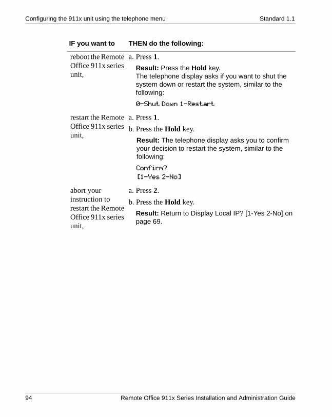
Configuring the 911x unit using the telephone menu Standard 1.1
reboot the Remote Office 911x series unit,
a. Press 1.Result: Press the Hold key.The telephone display asks if you want to shut the system down or restart the system, similar to the following:0-Shut Down 1-Restart
restart the Remote Office 911x series unit,
a. Press 1.b. Press the Hold key.
Result: The telephone display asks you to confirm your decision to restart the system, similar to the following:Confirm?[1-Yes 2-No]
abort your instruction to restart the Remote Office 911x series unit,
a. Press 2.b. Press the Hold key.
Result: Return to Display Local IP? [1-Yes 2-No] on page 69.
IF you want to THEN do the following:
94 Remote Office 911x Series Installation and Administration Guide

October 2001 Configuring the 911x unit using the telephone menu
confirm your instruction to restart the Remote Office 911x series unit,
a. Press 1 to restart the Remote Office 911x series unit.b. Press the Hold key.
Result: The telephone display informs you that it is restarting the system, similar to the following:Restarting the SystemPlease Wait...
c. When the system restarts, the telephone display returns to its normal state, showing the time and date, similar to the following:JAN 01 12:13 P
d. If the telephone is connected to a PBX, it is ready to send and receive telephone calls as normal.
e. If the telephone is not connected to a PBX, the telephone display shows a message similar to the following:
HOSTLESS MODE
shut down the Remote Office 911x series unit, thereby disabling all functionality on the unit,
a. Press 0.b. Press the Hold key.
Result: The telephone display asks you to confirm your instruction to shut down the Remote Office 911x series unit, similar to the following:Confirm?[1-Yes 2-No]
Note: Only choose the shut down option when you have physical access to the remote unit. You must be able to disconnect then reconnect power to the Remote Office 911x series unit to be able to access the unit again.
IF you want to THEN do the following:
Remote Office 911x Series Installation and Administration Guide 95

Configuring the 911x unit using the telephone menu Standard 1.1
abort your instruction to shut down the Remote Office 911x series unit,
a. Press 2.b. Press the Hold key.
Result: Return to Display Local IP? [1-Yes 2-No] on page 69.
confirm your instruction to shut down the Remote Office 911x series unit,
a. Press 1.b. Press the Hold key.
Result: The telephone display prompts you to turn off the Remote Office 911x series unit, similar to the following:Please remove SystemPower.
IF you want to THEN do the following:
96 Remote Office 911x Series Installation and Administration Guide

C h a p t e r 5
Changing configuration settings using Configuration Manager
In this chapter Before you begin 98
Remote Office 911x series unit system configuration 99
IP configuration 104
RLC connection configuration 107
Remote Office 911x Series Installation and Administration Guide 97

Changing configuration settings using Configuration Manager Standard 1.1
Before you begin
This section describes the configuration settings that apply to Remote Office 911x series units. If you need remote serial access to Configuration Manager, use a remote management software application.
Note: Nortel Networks recommends that you use the telephone menu set to perform the initial configuration for the Remote Office 911x series unit. Refer to Chapter 4, “Configuring the 911x unit using the telephone menu.” Once configured, you can then use the Configuration Manager for changes, administration, and firmware upgrades. For a more detailed description of Configuration Manager, refer to the Reach Line Card Installation and Administration Guide (NTP 555-8421-210).
98 Remote Office 911x Series Installation and Administration Guide

October 2001 Changing configuration settings using Configuration Manager
Remote Office 911x series unit system configuration
This section describes the settings that apply to the Remote Office 911x series unit system.
Getting there 911x ➝ Configuration Manager ➝ 911x System Configuration
Remote Office 911x series unit System Configuration property sheet
Remote Office 911x Series Installation and Administration Guide 99

Changing configuration settings using Configuration Manager Standard 1.1
Configuring the system settings
To configure the system settings, complete the following procedure:
1 Complete the fields as described in the “Remote Office 911x System Configuration field descriptions”, on page 101.
2 Click on the OK button to save the information in the temporary work file.
3 Click on the Send button to update the Remote Office 911x series unit with the new information.
IF you are THEN
logged on to the Remote Office 911x series unit,
the changes are written into the Remote Office 911x series unit’s buffer.To save the changes in flash memory, choose Upload/Download › Save to Flash from the Menu Bar.
not logged on to the Remote Office 911x series unit,
the Confirmation Manager dialog box displays, similar to the following:
Do one of the following:a. Log on to the Remote Office 911x series
unit and then click on the Send button.
b. Save the changes to a file on your administration PC using the File -›Save As command.
100 Remote Office 911x Series Installation and Administration Guide

October 2001 Changing configuration settings using Configuration Manager
Remote Office 911x System Configuration field descriptions
Field Description
Unit ID Assign a number between 1 and 20 to the Remote Office 911x series unit that you are configuring. This number:! must be different from numbers assigned to other units
connected to the same RLC! must be consistent with the configuration on the RLC
for this unit ID
Node Name Enter your site name. The node name identifies this Remote Office 911x series unit in the remote network.
DSP Gain Select the number of decibels (dB) that you want to add to, or subtract from, the strength of the incoming signal before the DSP processes it. Valid options are: 9, 6, 3, 0, -3, -6, -9, -12, and -15.
Note: Change this setting at the remote site to address a problem with signal strength at the host site.
Time Offset Click on the up or down arrows to change the time zone difference from the host PBX.
Note: The time can be changed in 15-minute intervals only.
Emergency Activation Code
If you are using the PSTN to route calls, then enter the number your community dials to reach an emergency service.If you are using only the IP network to route calls, leave this field blank.
Remote Office 911x Series Installation and Administration Guide 101

Changing configuration settings using Configuration Manager Standard 1.1
SPRE Codes: Online Enter the SPRE code (maximum seven digits) that is used to place your site into online mode, or accept the default. The default is #99.
Note: The SPRE code is automatically prefixed with the pound sign. This means users must dial # before the SPRE code when going into online mode.
SPRE Codes: Offline Enter the SPRE code (maximum seven digits) that is used to put your site into offline mode, or accept the default code. The default is #98.
Note: The SPRE code is automatically prefixed with the pound sign. This means users must dial # before the SPRE code when going into offline mode.
SPRE Codes: Registration Enter the SPRE code (maximum seven digits) that engages the user’s telephone with a multi-user or dynamic port, or accept the default code. The default is #97.
Note: The SPRE code is automatically prefixed with a pound sign (#). This means users must dial # before the SPRE code when registering for a port.
SPRE Codes: DeRegistration
Enter the SPRE code (maximum seven digits) that disengages the user from a multi-user or dynamic port, or accept the default code. The default is #96.
Note: The SPRE code is automatically prefixed with a pound (#) sign. This means users must dial # before the SPRE code when disengaging from a port.
Local Call: Status Click on the Enable option button, if you want to place local calls over the PSTN.Click on the Disable option button, if you do not want to place local calls over the PSTN.
Field Description
102 Remote Office 911x Series Installation and Administration Guide

October 2001 Changing configuration settings using Configuration Manager
Local Call: Local Calling Key Position
Select the key you want to use for the local call key. Be sure that the key you choose as the Local Calling Key at the remote site does not conflict with PBX key assignments.
Local Call: Autohold Click on the Enable option button if you want to be able to switch between local and remote calling keys without losing an active call.Click on the Disable option button if you want to disconnect active calls when you access another call without pressing the Hold key first.
Local DN Enter the DN of the local calling key.
Analog Localization Select one of three options from the drop down list box to modify the localization setting for this unit. Valid options: FCC, CTR21, and Custom.
Modem Tones Click on the Enable option button to activate modem tones on the telephone.Click on the Disable option button to deactivate modem tonesIf you are using only the IP network to route calls, leave this field blank.
Phone Type Select the type of digital telephone that the Remote Office 911x series unit attaches to, using the drop down list box. Valid options are: M2008, M2216, M2616, M2616CT, M3310, M3820, M3902, M3903, M3904, M3905, and OTHER.
Addon Module Type Select the type of addon module attached to the Remote Office 911x series unit’s telephone, if the telephone is an M3904 or M3905 telephone. Valid options are: DBA, KBA, and Not Configured.
Field Description
Remote Office 911x Series Installation and Administration Guide 103

Changing configuration settings using Configuration Manager Standard 1.1
IP configuration
This section explains how to change the IP address, subnet mask, and default gateway for the Remote Office 911x series unit.
Getting there 911x ➝ Configuration Manager ➝ IP Configuration
IP Configuration property sheet
104 Remote Office 911x Series Installation and Administration Guide

October 2001 Changing configuration settings using Configuration Manager
Configuring IP information
To change the IP information, complete the following procedure:
1 Complete the fields of the IP Configuration property sheet as described in “IP Configuration field descriptions”, on page 106.
2 Click on the OK button to save the information in the temporary work file.
3 Click on the Send button to update the Remote Office 911x series unit with the new information.
4 Restart the Remote Office 911x series unit.
Note: To restart a Remote Office 911x series unit, use the procedure found under “Restarting the system”, on page 170.
IF you are THEN
logged on to the Remote Office 911x series unit,
the changes are written into the Remote Office 911x series unit’s buffer.To save the changes in flash memory, choose Upload/Download › Save to Flash from the Menu Bar.
not logged on to the Remote Office 911x series unit,
the Configuration Manager dialog box displays, similar to the following:
Do one of the following:a. Log on to the Remote Office 911x series
unit, then click on the Send button again.
b. Save the changes to a file on your administration PC.
Remote Office 911x Series Installation and Administration Guide 105

Changing configuration settings using Configuration Manager Standard 1.1
IP Configuration field descriptions
Field Description
Automatic DHCP Configuration
! Click on the Obtain IP Address from Server option button to allow the Remote Office 911x series unit to use an IP address dynamically assigned by a DHCP server on the IP network.Result: Configuration Manager disables the IP Address, IP Network Mask, and IP Gateway fields.
! Click on the Configure IP Address option button to manually configure a static IP address for the Remote Office 911x series unit.Result: Configuration Manager enables the IP Address, IP Network Mask, and IP Gateway fields.
Address Information—IP Address, IP Network Mask, IP Gateway
If you clicked on the Configure IP Address option button, enter the IP address, IP network mask, and IP gateway in the appropriate fields.
DiffServ CodePoint ! Click on the Enable option button if you want to allow DiffServ prioritizing in the IP header.
! Click on the Disable option button if you do not want to allow DiffServ prioritizing.
802.1p Mapping ! Click on the Enable option button, if you want to allow 802.1p prioritizing in the IEEE Media Access Control layer.
! Click on the Disable option button, if you do not want to allow 802.1p prioritizing.
106 Remote Office 911x Series Installation and Administration Guide

October 2001 Changing configuration settings using Configuration Manager
RLC connection configuration
This section shows you how to change the RLC connection information needed by the Remote Office 911x series unit to establish connections with the RLC on the host PBX.
Getting there 911x ➝ Configuration Manager ➝ RLC Connection Configuration
RLC Connection Configuration property sheet
Remote Office 911x Series Installation and Administration Guide 107

Changing configuration settings using Configuration Manager Standard 1.1
Configuring the RLC connection information
To change the RLC connection information, complete the following procedure:
1 Complete the fields of the RLC Connection property sheet as described in “RLC Connection configuration field descriptions” on page 109.
2 Click on the OK button to save the information in the temporary work file.
3 Click on the Send button to update the Remote Office 911x series unit with the new information.
IF you are THEN
logged on to the Remote Office 911x series unit,
the changes are written into the Remote Office 911x series unit’s buffer.To save the changes in flash memory, choose Upload/Download › Save to Flash.
not logged on to the Remote Office 911x series unit,
the Configuration Manager dialog box displays, similar to the following:
Do one of the following:a. Log on to the Remote Office 911x series
unit, then click on the Send button again.
b. Save the changes to a file on your administration PC.
108 Remote Office 911x Series Installation and Administration Guide

October 2001 Changing configuration settings using Configuration Manager
RLC Connection configuration field descriptions
Field Description
Unit ID The RLC’s non-configurable unit ID of 254.
RLC Port Number Enter the RLC voice port number designated for the Remote Office 911x series unit on the RLC Remote connection configuration property sheet.
IP Connection Click on the Enable option button, if you want to route calls over your IP network.Click on the Disable option button, if you do not want to route calls over your IP network.
IP Connection: IP Address Enter the RLC’s IP address. The Remote Office 911x series unit uses this IP address to connect to the RLC over the IP network.
IP Connection: IP Signaling
Click on the Permanent option button to configure this port’s IP connection to be up at all times.Click on the On Demand option button to configure this port’s IP connection to be up only when needed.Refer to “Deployment”, on page 42 for help in determining which setting to configure.
PSTN Connection Click on the Enable option button, if you want to route calls over PSTN.Click on the Disable option button, if you do not want to route calls over PSTN.
Remote Office 911x Series Installation and Administration Guide 109

Changing configuration settings using Configuration Manager Standard 1.1
PSTN Connection: PSTN Number to Connect to RLC
If you enabled the PSTN connection, enter the telephone number used to connect to the RLC.The telephone number can contain the following digits and characters: 0 through 9, #, *, comma (,), period (.), and dash (-).! caller ID separator: “.” (period)! caller ID separator and 1/2 second delay: “,” (comma)! null separator: “-” (dash)
Security Level Select No Security from the drop down list box if you do not want the RLC to perform a security check. Select Provision ID from the drop down list box to require the RLC to perform a security check every time a user tries to log on to a remote unit. This action enables the Security ID fields.
Security ID: Outbound Security ID
Enter the 10-digit Remote Office 911x series unit security identifier.
Security ID: Inbound Security ID
Enter the 10-digit RLC security identifier.
Field Description
110 Remote Office 911x Series Installation and Administration Guide

C h a p t e r 6
Using the digital telephone
In this chapter Modes of operation 112
Placing and receiving calls 115
Indicator updates 118
Display messages 120
Telephone features operation 122
Going online and offline 125
Remote Office 911x Series Installation and Administration Guide 111

Using the digital telephone Standard 1.1
Modes of operation
Digital telephones at your Remote Office 911x series unit site can operate in the following modes:
! host-controlled ! locally controlled ! online to host PBX ! offline from host PBX
Host-controlled mode
Host-controlled mode means that the host PBX controls the following:
! some display messages that appear on your telephone! indicator updates such as the message waiting indicator! calls that you receive from or place to someone at the host PBX site
In host-controlled mode, a voice path is established to the host PBX and signaling messages are passed between the host PBX and the Remote Office 911x series unit.
Locally controlled mode
Locally controlled mode means that calls are placed or received through your local telephone service provider.
112 Remote Office 911x Series Installation and Administration Guide

October 2001 Using the digital telephone
Relationship between host-controlled and locally controlled modes
Both the host-controlled and locally controlled modes can be used at the same time. When placing or receiving calls, the call modes are controlled by the following telephone keys:
! host calling key (also known as the primary DN key)! local calling key (may sometimes be referred to as the secondary DN key)
Host calling keyThe host calling key is the main key used to place and receive calls. For example, if someone from Finance at the Head Office calls you, the call rings on this key. Similarly, if you need to call someone in Payroll at the Head Office, you place the call using this key.
Local calling keyThe local calling key is the key used to place and receive local calls. For example, you use this key if you want to call one of your local customers. Your telephone has one local calling key.
Note: Ensure that the local calling key is not configured on the host PBX. Local configurations override host PBX settings for the same key.
Online mode
When in online mode, calls initiated on the host calling key are directed through the host PBX. The display on your digital telephone set shows Online Mode.
Offline mode
When in offline mode, you cannot place or receive calls through the host PBX over either the PSTN or IP network. You can only place or receive calls through your local telephone service provider if your station has been granted locally controlled call capability. The display on all digital telephone sets show Offline Mode.
Remote Office 911x Series Installation and Administration Guide 113

Using the digital telephone Standard 1.1
Why offline mode is important
Your organization is concerned about telephone costs and, as such, wants to ensure that the PSTN line at your site is used for host-controlled calls during business hours only. This is especially important when the PSTN connection between the host PBX and your site is defined as permanent (always on) rather than on demand. A permanent PSTN connection means the line remains active all the time and incurs charges unless it is put into offline mode.
What controls the online and offline modes
The online and offline modes can be controlled by one or both of the following:
! online/offline schedule configured for your site on the RLC at the host PBX! special prefix (SPRE) codes configured on the Remote Office 911x series
unit at your site
For more information, refer to “SPRE Codes: Online” on page 102 and “SPRE Codes: Offline” on page 102.
114 Remote Office 911x Series Installation and Administration Guide

October 2001 Using the digital telephone
Placing and receiving calls
The way that you place outgoing calls depends on the calling key that you use. The calling key that you receive calls on depends upon where the call originates.
Receiving incoming calls
A Remote Office 911x series unit receives incoming calls according to the following conditions:
! When the remote unit is offline, you can receive locally controlled incoming calls.
! When the remote unit is configured as IP-only at the RLC and the PSTN is disabled in the RLC detail configuration, you can receive locally controlled incoming calls.
! When both PSTN and IP modes are configured with permanent allocation, you cannot receive locally controlled calls.Refer to “Priority” in the Reach Line Card Installation and Administration Guide (NTP 555-8421-210) for more information.
Refer to “Deployment” on page 42 for more information.
Note: If an incoming call is not answered within a specified number of rings, the RLC transfers the call to a bridge port. The RLC then places a call through the host PBX to a DN defined for the user. This DN may be assigned the user’s voice mail, or may be a redirection to another DN.
Methods for placing outgoing calls
You can place an outbound call from a Remote Office 911x series unit station in one of the following ways:
! method 1: Lift the telephone handset.This method automatically initiates a host-controlled call.Note: If you then press the local calling key, the call moves to locally controlled mode, and the host PBX connection is released.
! method 2: Press a calling key.
Remote Office 911x Series Installation and Administration Guide 115

Using the digital telephone Standard 1.1
Pressing a host calling key initiates a host-controlled call. Pressing the local calling key, initiates a locally controlled call.
Placing a host-controlled call
To place a host-controlled call, complete the following procedure:
1 Lift the telephone handset or press the host calling key.
Result: You hear a dial tone over a connection with the host PBX.
Note: If a connection to the host PBX cannot be established within a time-out period or no resources are available to carry the call, you hear a reorder dial tone (fast busy signal), and one of the following messages appears on the telephone display:
! Release and Try Again
! Bandwidth Limit
! DSP Limit
Bandwidth limit indicates that there was not enough bandwidth available in the system to complete the requested task.
DSP limit indicates that there were not enough available DSP resources in the system to complete the requested task.
2 Dial the number of the party you want to call.
Result: The host PBX receives and processes the dialed digits, and rings the called party.
116 Remote Office 911x Series Installation and Administration Guide

October 2001 Using the digital telephone
Placing an outgoing locally controlled call
To place an outgoing locally controlled call, complete the following procedure:
1 Lift the telephone handset, then press the local calling key.
Result: A connection is established with the central office and you hear a dial tone.
2 Dial the number of the party you want to call.
Result: Your local telephone service provider receives and processes the dialed digits, and rings the called party.
To call another station at your site—locally controlled mode
If your site is equipped with multiple Remote Office 911x series units and you want to use the local calling key to place the call, dial the PSTN number (seven digits) of the person you want to call.
To call another station at your site—host-controlled mode
Station-to-station calls should be attempted through the host PBX to allow all stations configured as multiple appearance DNs (MADNs) to ring and provide access to voice mail, if the call is not answered.
If a connection cannot be established through the host PBX, you can use the local calling key to place the station-to-station call.
1 Lift the telephone handset or press the host calling key.
Result: A connection is established with the host PBX and you hear a dial tone. The indicator beside the host calling key lights up.
2 Dial the extension of the party you wish to reach.
Result: The host PBX receives and processes the dialed digits, and rings the station as well as any other stations that include the dialed DN as an MADN key.
Note: The MADN stations could be located at another site (such as the host PBX site). If the call is answered by a MADN station at another site, a voice path to the host PBX is established and the call proceeds.
Remote Office 911x Series Installation and Administration Guide 117

Using the digital telephone Standard 1.1
Indicator updates
Digital telephone indicators reflect the current status of the telephone. For example, they identify when calls are waiting, active, on hold, or (if your office has voice mail) that messages are waiting.
The host PBX updates indicators when a connection between the host PBX and Remote Office 911x series unit is active.
Host-controlled indicator updates
The host PBX automatically updates indicators for host-controlled features each time any of the following occur:
! the host PBX receives an incoming call from your site! the host PBX processes an outgoing call from your site! the host PBX sends a message waiting indicator (MWI) update
Note: When online with a permanent connection to the host PBX, a remote site receives constant telephone indicator updates.
Locally controlled indicator updates
The Remote Office 911x series unit updates the following indicators (that is, these indicator updates are locally controlled):
! host and local calling key indicatorsThe indicator lights up when you lift the handset, or when you press the line key.Note: The Remote Office 911x series unit passes key presses and the on- or off-hook status for the host calling key to the host PBX.
! handsfree! mute
118 Remote Office 911x Series Installation and Administration Guide

October 2001 Using the digital telephone
PSTN line usage and the local calling indicator
The following two instances of PSTN line usage cause the local calling indicator to remain lit solid:
! a remote call on the PSTN lineWhen there is a remote call on the local calling (PSTN) key, the local calling indicator stays lit, indicting that the line is active.
! a signaling connection over the PSTN lineWhen the RLC at the host site and the Remote Office 911x series unit at the remote site exchange information. This information, or signaling, travels over the PSTN line. When this happens, the local calling indicator stays lit, indicting that the line is active.
Remote Office 911x Series Installation and Administration Guide 119

Using the digital telephone Standard 1.1
Display messages
This section describes the messages that can appear on your digital telephone display.
Message descriptions
Message Description
Going Offline in 30 Secs
Going Offline in 20 Secs
Going Offline in 10 Secs
This message warns you that all digital telephones at this site are about to go offline in the number of seconds indicated.If any calls are active, they disconnect when the offline mode activates.To override, enter the online SPRE code.
Hostless Mode The connection to the host PBX cannot be established. The host PBX may be temporarily unavailable.You can still place local calls by using the local calling key.
Note: If Hostless Mode persists, contact your system administrator.
Logged In If this message appears on your station, your station participates in a multi-user or dynamic pool port on the RLC. Your station is logged on.
Note: This message only displays for approximately 10 seconds.
120 Remote Office 911x Series Installation and Administration Guide

October 2001 Using the digital telephone
Offline Mode This means you cannot place calls through the host PBX. Notes: ! If you need to place a call through the host PBX while
in offline mode, enter the online SPRE code. Refer to “SPRE Codes: Online” on page 102 for further details.
! The Offline Mode message is not persistent on the M3903 telephone display. This message sometimes does not appear for the entire Offline period.
Online Mode This means you can place and receive calls through the host PBX.
Port Already in Use If this message appears on your station, your station participates in a multi-user or dynamic pool port on the RLC.This message appears if the port that you are attempting to log on to is already being used by someone else.
Port Not Logged In If this message appears on your station, your station participates in a multi-user or dynamic pool port on the RLC. Your station is logged off.
Release and Try Again There are not enough DSP resources to process the call. Try again at a later time.
Note: Ensure to initiate calls from the appropriate calling key according to the following parameters:
! Use the host calling key to call someone at the host PBX site
! Use the local calling key to place a local PSTN call or to call another station at your site.
Bandwidth Limit There is not enough bandwidth to complete the requested action.
DSP Limit There were not enough DSP resources to complete the requested action.
Message Description
Remote Office 911x Series Installation and Administration Guide 121

Using the digital telephone Standard 1.1
Telephone features operation
This section describes how to use the following digital telephone features in host-controlled modes:
The conference, transfer, and call forward features are only supported for host-controlled calls.
Emergency service calls
The Remote Office 911x series unit allows you to program an emergency number (for example, 911). You can initiate an emergency service call with the programmed number on either the host calling key (primary DN key) or the local calling key.
If using the IP network to route calls, do not dial the emergency service number on a station connected to a Remote Office 911x series unit.
Hold
When you press the Hold key on a host-controlled call, the holding party receives the Hold treatment defined on the host PBX. For example, if the host PBX is configured to play music for the holding parties, then the holding party hears music. You can press the local calling key to place a new call.
When you are on a locally controlled call, you can automatically place that call on hold by pressing the host calling key. To do this, you must enable the Auto Hold feature on your station. Refer to “Local Call: Autohold” on page 103 for further details. If Auto Hold is not enabled, and you press the local calling key while a host-controlled call is active, that call is disconnected.
! call forward! call transfer! call waiting
! conference! emergency service calls! hold
122 Remote Office 911x Series Installation and Administration Guide

October 2001 Using the digital telephone
When you press the Hold key on a locally controlled call, the holding party hears silence. Since Remote Office 911x series units have only one local calling key, you cannot place another locally controlled call while the first call is on Hold. However, when you place a locally controlled call on Hold, you can still place a host-controlled call.
Call WaitingSince the Remote Office 911x series unit does not use host-controlled indicators and the locally controlled indicators are not defined on the host PBX, there are never any indicator conflicts when a call is presented to the station.
However, since the host PBX is not aware when locally controlled calls are active, the host PBX may try to present a call and ring your station while you are busy with a locally controlled call. The Remote Office 911x series unit always checks the status of your station before ringing it. If your station is busy with a call, the alert tone is sounded instead. For host-controlled calls routed over PSTN ensure that call waiting is disabled at the CO. If a call comes in when the remote unit has a call in a QoS transitioning situation, the incoming call waiting signal disrupts the connection. The call waiting signal drops the transitioned PSTN call.
How Call Waiting works in host-controlled modeIf you are busy with a host-controlled call, incoming calls are handled as follows:
! An incoming host-controlled call is directed to the call waiting key by the host PBX.
! An incoming locally controlled call flashes the local calling key indicator and sounds the alert tone.
How Call Waiting works in locally controlled modeIf you are busy with a locally controlled call, an incoming host-controlled call flashes the host calling key and sounds the alert tone.
! If you have enabled QoS Transitioning Technology, Nortel Networks recommends that you disable call waiting.
! Call waiting presents CLID and CPND information according to the options that your service provider offers and what you have subscribed to.
Remote Office 911x Series Installation and Administration Guide 123

Using the digital telephone Standard 1.1
Call Transfer
A call on the host calling key can be transferred. You can complete an announced or unannounced (blind) transfer. Refer to your telephone manual for the proper procedures on completing an unannounced transfer.
If a host-controlled call is to be transferred to a remote trunk from a remote station (remote trunk access digit dialed), the following occurs:
! Dialed digits are used to place a remote trunk call, but are not forwarded to the host PBX.
! A voice path is established between the remote trunk and a bridge port on the host line card.
! The number dialed to the host for the new call is the DN of that bridge port.
To transfer a call, complete the following procedure:
1 Press the Transfer key.
Result: The active call is placed on hold and you hear dial tone.
2 Dial the number that you want to transfer the call to.
3 Press the Transfer key again to complete the transfer.
Note: You can press the Transfer key while the call is still ringing, or after the called party answers.
Conference
The Conference feature is supported for host-controlled calls only. You cannot conference in someone who must be called through the local PSTN.
Call Forward
Call forward is supported for host-controlled calls only. Your station might be programmed to forward all calls, forward calls when your station is busy, or forward calls when you do not answer.
124 Remote Office 911x Series Installation and Administration Guide

October 2001 Using the digital telephone
Going online and offline
Your Remote Office 911x series unit site can operate in either online mode or offline mode. This is controlled by one or both of the following:
! SPRE codes to manually toggle between online and offline modes.! An online/offline schedule on the host PBX to automatically toggle your
site between online and offline modes.
For a description of the online and offline modes, refer to “Modes of operation” on page 112.
Using the SPRE code to place your unit in online mode
To use the SPRE code to place your unit in online mode, complete the following procedure:
1 Lift the telephone handset, or press the local calling key.
2 Press the pound (#) key followed by the online SPRE code.
Note: Contact your system administrator for the online SPRE code.Result: The connection to the host PBX is initiated and negotiated with the host PBX. During this negotiation period (up to five seconds), you cannot place host-controlled calls. When negotiation is completed and connection to the host PBX has been established, Online Mode appears on the telephone display and the system is ready to place and receive host calls.
Using the SPRE code to place your unit in offline mode
To use the SPRE code to place your unit in offline mode, complete the following procedure:
1 Dial the pound (#) key followed by the offline SPRE code.
Note: Contact your system administrator for the online SPRE code.Result: Offline Mode appears on the telephone display.
Remote Office 911x Series Installation and Administration Guide 125

Using the digital telephone Standard 1.1
Overriding an automatic offline event from the host PBX
If the host PBX attempts to process an offline event while you are on a host-controlled call, you are alerted by both an audible alert and a display message indicating that you are about to go offline in 30, 20, or 10 seconds. If you ignore this warning, your call disconnects.
To prevent your call from being disconnected, enter the online SPRE code. You can do this without putting your call on hold first. The online SPRE code cancels the offline event, leaving your telephone online until the next offline event occurs.
On-Demand and Permanent Allocation to Remote Office 911x series units
Nortel Networks recommends that you do not enable the On-Demand feature when configuring a PSTN port to the Remote Office 911x series unit. Doing so can cause the following to occur:
! The Remote Office 911x series unit can activate voice-mail prematurely (after one or two rings).
! The incoming host-controlled caller hears ringback.
Note: Incoming locally controlled callers may hear a busy signal or modem tones. Do not advertise this number for local calls.
For more information about on-demand and permanent allocation, refer to “Deployment” on page 42.
126 Remote Office 911x Series Installation and Administration Guide

C h a p t e r 7
Administration
In this chapter Changing the administration password 128
Creating a backup configuration file 130
Restoring the configuration 133
Display logs 138
Statistics screens 142
Verifying the firmware and software version 162
Obtaining the latest upgrade file 164
Extracting upgrade files from the download file 165
Performing a firmware upgrade 167
Restarting the system 170
Performing a software upgrade 171
Remote Office 911x Series Installation and Administration Guide 127

Administration Standard 1.1
Changing the administration password
Two layers of password security protect the Remote Office 911x series unit’s configuration. If you want to secure the Remote Office 911x series unit’s configuration, then change the following items:
! Configuration Manager passwordThis password prevents unauthorized users from performing offline configuration changes.
! Remote Office 911x series unit’s passwordThis password prevents unauthorized users from performing online changes of the configuration residing in the Remote Office 911x series unit’s flash memory.
Note: Make sure that you record the password and store it in a safe, secure location. If you forget or lose the password, contact your Nortel Networks customer support representative.
Getting there 911x ➝ Configuration Manager
Changing the Configuration Manager password
To change the Configuration Manager password, complete the following procedure:
1 From the Menu Bar, choose Connect ➝ Change Password ➝ Local.
Result: The Change Password dialog displays, similar to the following:
128 Remote Office 911x Series Installation and Administration Guide

October 2001 Administration
2 Complete the fields in the Change Password - Local dialog box.
3 Click on the OK button.
Changing the Remote Office 911x series unit’s password
To change the Remote Office 911x series unit’s password, complete the following procedure:
1 From the Menu Bar, choose Connect ➝ Change Password ➝ Node.
Result: The Change Password dialog box displays, similar to the following:
2 Complete the fields in the Change Password - Node dialog box.
3 Click on the OK button.
ATTENTION Do not change the Remote Office 911x series unit’s password until the system is up and working.
Remote Office 911x Series Installation and Administration Guide 129

Administration Standard 1.1
Creating a backup configuration file
Create a backup copy of the Remote Office 911x series unit’s configuration by downloading the configuration flash memory to a text file on your administration PC. Nortel Networks recommends that you create a backup of your configuration file whenever you make configuration changes or after you perform a firmware upgrade.
Storing backup configuration files
The Remote Office 911x series unit is an extension of the telecommunications and data network. It is extremely important that you keep a backup copy of the Remote Office 911x series unit’s configuration. If the Remote Office 911x series unit’s flash memory or configuration becomes corrupted or is lost, you can easily restore it.
Store the configuration file in a safe, secure location, such as on backup tape or other media that is stored offsite.
Nortel Networks recommends that you keep the backup files indefinitely.
Getting there 911x ➝ Configuration Manager
130 Remote Office 911x Series Installation and Administration Guide

October 2001 Administration
Creating the backup file
To create the backup file:
1 From the Menu Bar, choose Upload/Download ➝ Download Config.
Result: The Download Configuration dialog box displays, similar to the following:
2 Choose the mode you want to use for the file transfer according to the following table:
IF you wish to save the configuration file to THEN do the following:
the administration PC, Click on the Dump option button.
a different location on the IP network,
1 Click on the TFTP option button.Result: This enables the IP Address fields.
2 Enter the IP address of the PC that you want to save the configuration file on.
Remote Office 911x Series Installation and Administration Guide 131

Administration Standard 1.1
3 Click on the Browse button and navigate to the folder where you want to keep the configuration text file.
4 Enter a name for the file in the File name field.
Note: This configuration file becomes your backup file, so ensure the file name is meaningful. The file name’s extension must be .TXT.
5 Click on the Download button.
Result: The Download configuration dialog box closes, and the following message displays in the status bar at the bottom of the screen:
Downloading Config From Board
When the download is complete, the Downloaded Configuration Data dialog box displays, similar to the following:
6 Click on the OK button.
132 Remote Office 911x Series Installation and Administration Guide

October 2001 Administration
Restoring the configuration
Restore the Remote Office 911x series unit’s configuration in flash memory by uploading a configuration text file from your administration PC.
Perform the upload over the IP network using the TFTP protocol. You must have a TFTP server application running on your administration PC. The TFTP server’s base directory must point to the directory that contains the configuration file you want to upload.
Before you begin
Before you can upload the configuration file to the Remote Office 911x series unit, you must complete the following steps:
1 Start the TFTP server application.
2 Ensure the TFTP base directory points to the location of the configuration file.
Getting there 911x ➝ Configuration Manager
Remote Office 911x Series Installation and Administration Guide 133

Administration Standard 1.1
Uploading a configuration file over the IP network
To upload a configuration file over the IP network, complete the following procedure:
1 Navigate to the location of the configuration file.
2 From the Menu Bar, choose ➝ Upload/Download ➝ Upload Config.
Result: The Upload Configuration dialog box displays, similar to the following:.
3 Enter the IP address of the TFTP server in the IP Address fields.
Note: Since the TFTP server application is running on your administration PC, this is the IP address of that PC.
134 Remote Office 911x Series Installation and Administration Guide

October 2001 Administration
4 Click on the Browse button.
Result: The Open dialog box displays, similar to the following:
5 Ensure the Files of type list drop down box shows Text File (*.TXT)
6 Navigate to the folder containing the configuration file.
7 Select the file, then click on the Open button.
Result: The Upload Configuration dialog box displays with the file you selected shown in the File Name field.
Remote Office 911x Series Installation and Administration Guide 135

Administration Standard 1.1
8 Click on the Upload button.
Result: The middle of the Upload Configuration dialog box displays status messages relating to the upload. The following is an example.
.
CAUTION
Risk of incorrect operation due to partial configurationDo not interrupt the configuration upload. If you interrupt the configuration upload, this results in an incomplete configuration in the Remote Office 911x series unit’s database. If the configuration upload is interrupted, repeat this procedure immediately.
136 Remote Office 911x Series Installation and Administration Guide

October 2001 Administration
Note: Do not ignore error messages in Save to Flash process. If Save to Flash fails, retry uploading and saving to Flash. If the problem persists, check the file being uploaded and report the problem to Nortel Networks.
9 From the Upload Configuration dialog box, click on the Save to Flash button.
Result: The FLASH CONFIG dialog box displays, similar to the following:
10 Click on the Yes button.
Result: The following message displays in the status bar at the bottom of the screen:
Saving to Flash in Progress
When the save is finished, the following message displays in the middle of the Upload Configuration dialog box:
CONFIGURATION IS UPDATED INTO FLASH...
11 Click on the Close button.
12 Restart the RLC.
Note: For instructions, refer to “Restarting the system” on page 170.
IF the upload was THEN
successful, the following message displays:CONFIG UPLOAD SUCCESSFUL... USE SAVECFG TO UPDATE FLASH.
not successful, the following message displays in the middle of the Upload Configuration dialog box:CONFIG UPLOAD FAILED
For further instructions, refer to Chapter 8, “Troubleshooting”.
Remote Office 911x Series Installation and Administration Guide 137

Administration Standard 1.1
Display logs
The Remote Office 911x series unit keeps track of system performance through the maintenance of display logs. Each line, or display log, represents a separate action completed by the unit.
Use the display logs when troubleshooting system problems. Click on the Save Report button if you need to print the display logs to a text file. Refer to Configuration Manager Help for a complete listing of all display logs and the condition indicated by each.
Getting there 911x ➝ Configuration Manager
Viewing display logs
From the Menu Bar, choose Alarms/Stats/Logs ➝ Display Logs.
Result: The Remote Office 911x series unit lists the display logs it maintains in a window similar to the following. You can use the scroll bar to browse through the display logs.
138 Remote Office 911x Series Installation and Administration Guide

October 2001 Administration
Printing the display logs to a file
If you request technical support, your support representative can ask you to provide a copy of the display logs. To recreate the log in a file on your administration PC, use the following procedure:
1 After listing the display logs using the procedure explained under “Viewing display logs” on page 138, click on the Save Report button on the Display Logs window.
Result: The Save As dialog box displays, similar to the following:
2 Enter a name for the configuration in the File name field.
Result: Configuration Manager saves the display logs to a text file in the location indicated in the Save As dialog box.
Remote Office 911x Series Installation and Administration Guide 139

Administration Standard 1.1
Changing the number of display logs retained by the Remote Office 911x series unit
A Remote Office 911x series unit retains a maximum of 1000 display logs, each requiring one line of text. When the unit’s display logs reach 1000 lines, new display logs overwrite existing display logs on a first in, first out basis. If you want to change the number of display logs retained by the Remote Office 911x series unit, complete the following procedure:
1 From the Menu Bar, choose Alarms/Stats/Logs ➝ Resize Logs.
Result: The Resize Log dialog box displays, similar to the following:
Note: “Maximum logs” refers to the number of text lines, or messages, maintained by the Remote Office 911x series unit. The Remote Office 911x series unit currently retains a maximum of 1000 text lines.
2 Enter the maximum number of text lines you want maintained by the Remote Office 911x series unit in the Maximum Logs field.
3 Click on the OK button.
140 Remote Office 911x Series Installation and Administration Guide

October 2001 Administration
Clear logs
The Remote Office 911x series unit allows you to delete unneeded information by clearing the display logs. To discard or clear display logs that are no longer useful, complete the following procedure:
1 From the Menu Bar, choose Alarms/Stats/Logs ➝ Clear Logs.
Result: The CLEAR LOGS dialog box displays, similar to the following:
IF you select THEN
No, the Clear logs dialog box closes and the retained display logs remain as they are.
Yes, ! the Remote Office 911x series unit deletes its stored display logs.
! the LOGS cleared dialog box displays, similar to the following:
Click on the OK button.
Remote Office 911x Series Installation and Administration Guide 141

Administration Standard 1.1
Statistics screens
All statistics screens provided by the Alarms/Stats/Logs menu, function primarily to help you obtain information to provide to technical support personnel, upon request.
Getting there 911x ➝ Configuration Manager
Trunk Connection Statistics
Trunk Connection Statistics allow you to see the status of the active PSTN calls on the Remote Office 911x series unit. Use the Trunk Connection Statistics screen to determine if you need more trunk connections at your remote location.
142 Remote Office 911x Series Installation and Administration Guide

October 2001 Administration
Displaying the Trunk Connection Statistics screen
Choose Alarms/Stats/Logs ➝ Trunk Connection Statistics from the Menu Bar to display the Bandwidth Connection Statistics screen.
Result: Configuration Manager gathers statistics from the Remote Office 911x series unit and displays the Bandwidth Connection Statistics screen, similar to the example on page 142.
IF you want to THEN click
update the statistics with the latest information,
on the Refresh button.
create a text file containing these statistics,
on the Save to File button.
close the Trunk Connection Statistics screen,
on the Close button.
obtain descriptions of the statistics in the Trunk Connection Statistics screen,
on the Help button.
Remote Office 911x Series Installation and Administration Guide 143

Administration Standard 1.1
Trunk Connection Statistics field descriptionsThe following table describes the statistics on the Trunk Connection Statistics screen:
Statistic Description
Trunk Number RLC - Identifies the Network Port number used for the call. The third pair of numbers (the third item in the triplet) corresponds to the port on the RLC. 9150 - Identifies the ISDN BRI module and B-channel used for the call.911x - Identifies the only trunk available to the Remote Office 911x series unit with all zeroes.
Status Identifies the current status of the trunk. Valid options are: Active and Idle.
Call Type Identifies whether the call is a local call or a remote signaling call. Valid options are: Local and Signaling.
Remote ID Identifies the remote unit involved in the call.
Called Number Identifies the remote DN regardless of who initiated the call.
Start Time Identifies the time that the call began.
Close Time Identifies the time that the last call on this trunk ended.If the trunk is active, this statistic displays “NA”.
Duration Identifies the amount of time taken for the call.
144 Remote Office 911x Series Installation and Administration Guide

October 2001 Administration
Bandwidth Connection Statistics
Bandwidth Connection Statistics, similar to the following, allow you to see the amount of bandwidth that the logged-on Remote Office 911x series unit has available to it. Use the Bandwidth Connection Statistics to help you determine if you need to add more bandwidth on the PSTN or IP network connections.
To display the Bandwidth Connection Statistics screen, refer to “Displaying the Bandwidth Connection Statistics screen”, as follows. To obtain the definitions for the statistics presented on the Bandwidth Connection Statistics screen, refer to “Bandwidth Connection Statistics field descriptions” on page 147.
Remote Office 911x Series Installation and Administration Guide 145

Administration Standard 1.1
Displaying the Bandwidth Connection Statistics screen
Choose Alarms/Stats/Logs ➝ BW Connection Statistics from the Menu Bar to display the Bandwidth Connection Statistics screen.
Result: Configuration Manager gathers statistics from the Remote Office 911x series unit and displays the Bandwidth Connection Statistics screen, similar to the example on page 145.
IF you want to THEN click
update the statistics with the latest information,
on the Refresh button.
create a text file containing these statistics,
on the Save to File button.
close the Trunk Connection Statistics screen,
on the Close button.
obtain descriptions of the statistics in the Trunk Connection Statistics screen,
on the Help button.
146 Remote Office 911x Series Installation and Administration Guide

October 2001 Administration
Bandwidth Connection Statistics field descriptionsThe following table describes the statistics on the Bandwidth Connection Statistics screen:
Statistic Description
Remote Unit Number Identifies the remote unit that initiated the call.
Signaling Status Identifies whether a connection is up on this unit. Valid options are: Active and Idle.
No of Voice Calls on IP Identifies the number of calls in progress on this unit’s IP connection.
No of Voice Calls on PSTN Identifies the number of calls in progress on this unit’s PSTN connection.
Used IP BW Identifies the IP bandwidth in use on this unit.
Used Trunk BW Identifies the PSTN bandwidth in use on this unit.
Total Up Trunk BW Identifies the total PSTN bandwidth up and available to this unit.
IP QoS Status Identifies the quality of service level on this unit’s IP connection. Valid options are: Good and Bad.
Remote Office 911x Series Installation and Administration Guide 147

Administration Standard 1.1
Caller Information Statistics
Caller Information (Info) Statistics, similar to the following, allow you to see the type of call being made (IP or PSTN) and how often QoS transitions occur. Use the Caller Information Statistics to help you determine if the bandwidth used by the logged-on Remote Office 911x series unit.
To display the Caller Info Statistics screen, refer to “Displaying the Caller Info Statistics screen” on page 149. To obtain the definitions for the statistics presented on the Caller Info Statistics screen, refer to “Caller Info Statistics field descriptions” on page 150.
148 Remote Office 911x Series Installation and Administration Guide

October 2001 Administration
Displaying the Caller Info Statistics screen
Choose Alarms/Stats/Logs ➝ Caller Info Statistics from the Menu Bar to display the Caller Info Statistics screen.
Result: Configuration Manager gathers the statistics from the Remote Office 911x series unit and displays the Caller Info Statistics screen, similar to the example on page 148:
IF you want to THEN click
update the statistics with the latest information,
on the Refresh button.
create a text file containing these statistics,
on the Save to File button.
close the Trunk Connection Statistics screen,
on the Close button.
obtain descriptions of the statistics in the Trunk Connection Statistics screen,
on the Help button.
Remote Office 911x Series Installation and Administration Guide 149

Administration Standard 1.1
Caller Info Statistics field descriptionsThe following table describes the statistics on the Caller Info Statistics screen:
Statistic Description
Connection ID Identifies the serial number of this call through the lifetime of the logged on unit.
Remote ID Identifies the unit ID of the involved remote unit.
Current Media Identifies whether the call took place over the PSTN or IP network.
Type Identifies the type of call. Valid options are: Signaling, Voice, and Local.
Priority Identifies the priority setting of the involved trunk.Valid options are: PSTN Only, IP Only, High, and Normal.
Call BW Identifies the amount of bandwidth used by the call.
Start Time Identifies the time that the connection initiated.
Transitions to PSTN Identifies the number of times the RLC moved the call to the PSTN.
Transitions to IP Identifies the number of times the RLC moved the call to the IP network.
Last Transition to PSTN Identifies the last time the RLC moved the call from the IP network to the PSTN.
Last Transition to IP Identifies the last time the RLC moved the call from the PSTN to the IP network.
150 Remote Office 911x Series Installation and Administration Guide

October 2001 Administration
Digital Signal Processor (DSP) StatisticsDigital Signal Processor (DSP) Statistics, similar to the following, show information about the DSP devices on the logged-in Remote Office 911x series unit. Use this screen to determine the type of DSP on the unit and the functionality and performance of that DSP.
To display the DSP Statistics screen, refer to “Displaying the DSP Statistics screen” on page 152. To obtain the definitions for the statistics presented on the DSP Statistics screen, refer to “DSP Statistics field descriptions” on page 153.
Remote Office 911x Series Installation and Administration Guide 151

Administration Standard 1.1
Displaying the DSP Statistics screen
Choose Alarms/Stats/Logs ➝ DSP Statistics from the Menu Bar to display the DSP Statistics screen.
Result: Configuration Manager gathers statistics from the Remote Office 911x series unit and displays the DSP Statistics screen, similar to the example on page 151.
IF you want to THEN click
update the statistics with the latest information,
on the Refresh button.
create a text file containing these statistics,
on the Save to File button.
close the Trunk Connection Statistics screen,
on the Close button.
obtain descriptions of the statistics in the Trunk Connection Statistics screen,
on the Help button.
152 Remote Office 911x Series Installation and Administration Guide

October 2001 Administration
DSP Statistics field descriptionsThe following table describes the statistics on the DSP Statistics screen:
Statistic Description
Single Digit Device ID Identifies an internal sequence number for indexing this DSP device among all others on the RLC linked to the Remote Office 911x series unit.
Module Number Identifies this DSP Application Module’s module number on the RLC linked to the Remote Office 911x series unit. Valid options are: 0, 1, 2, 3, and 4.
Device Number Identifies the DSP device that processed the call.
In Service Identifies any voice channels operating on this DSP application module.
Total MIPS Identifies the total millions of instructions per second (MIPS) capacity for this DSP device.
Available Mips Identifies the millions of instructions per second (MIPS) currently available on this DSP device.
Total Channels Identifies the total channel capacity for this DSP device.
Total Voice Channels Identifies the total voice channel capacity for this DSP device.
Available Voice Channels Identifies the number of unused voice channels on this DSP device.
Total Modem Channels Identifies the number of channels on this DSP device that can transmit modem calls.
Remote Office 911x Series Installation and Administration Guide 153

Administration Standard 1.1
Available Modem Channels
Identifies the number of unused channels on this DSP that can transmit modem calls.
Total Flex Channels Identifies the number of channels on this DSP that can provide multiple functionalities.
Available Flex Channels Identifies the number of channels on this DSP currently available to provide multiple functionalities.
Total Tones Channels Identifies the number of channels on this DSP that can transmit tones.
Total Reserved Channels Identifies the number of special purpose channels on this DSP reserved for internal use.
Name Identifies the name of the DSP load, that is, the combination of DSP algorithms, on the DSP module.
Statistic Description
154 Remote Office 911x Series Installation and Administration Guide

October 2001 Administration
Ethernet Interface Statistics
Ethernet Interface Statistics, similar to the following, list information about the connection between the IP network and the Remote Office 911x series unit that is achieved over the unit’s Ethernet interface.
To display the Ethernet Interface Statistics screen, refer to “Displaying the Ethernet Interface Statistics screen” on page 156. To obtain the definitions for the statistics presented on the Ethernet Interface Statistics screen, refer to “Ethernet Interface Statistics field descriptions” on page 157.
Remote Office 911x Series Installation and Administration Guide 155

Administration Standard 1.1
Displaying the Ethernet Interface Statistics screen
Choose Alarms/Stats/Logs ➝ Ethernet Interface Statistics from the Menu Bar to display the Ethernet Interface Statistics screen.
Result: Configuration Manager gathers statistics from the Remote Office 911x series unit and displays the Ethernet Interface Statistics screen, similar to the example on page 155.
IF you want to THEN click
update the statistics with the latest information,
on the Refresh button.
create a text file containing these statistics,
on the Save to File button.
close the Trunk Connection Statistics screen,
on the Close button.
obtain descriptions of the statistics in the Trunk Connection Statistics screen,
on the Help button.
156 Remote Office 911x Series Installation and Administration Guide

October 2001 Administration
Ethernet Interface Statistics field descriptionsThe following table describes the statistics on the Ethernet Interface Statistics screen:
Statistic Description
Channel Identifies the Ethernet device that the statistics on that line apply to. Valid option is: 1
LAN Drv Identifies the LAN driver used by the call.
Admin Identifies the desired state of the port.
Oper Identifies the actual state of the port.
IfcType Identifies the interface type used by the call.
IfcNo Identifies the Ethernet interface used by the call. Valid options are: 0 (ELAN) and 1 (CLAN).
MTUlen Identifies the Maximum Transmission Unit for this interface.
Speed Identifies the data rate of this interface.
In - Octet Identifies the number of inbound bytes.
UPkts Identifies the number of inbound packets sent only to this recipient.
MPkts Identifies the number of inbound packets sent to multiple recipients.
Disc Identifies the number of packets discarded by the interface.
Err Identifies the number of error packets received by the interface.
Out - Octet Identifies the number of outbound bytes.
UPkts Identifies the number of outbound packets sent only to this recipient.
Remote Office 911x Series Installation and Administration Guide 157

Administration Standard 1.1
MPkts Identifies the number of outbound packets sent to multiple recipients.
Disc Identifies the number of outbound packets discarded by the interface due to resource problems.
Err Identifies the number of outbound packets discarded due to errors.
QLen Identifies the number of bytes in the interface’s outbound queue.
Statistic Description
158 Remote Office 911x Series Installation and Administration Guide

October 2001 Administration
Network Statistics
Network Statistics allow you to see the performance of the Remote Office 911x series unit in terms of the transmission and reception of frames and packets during the last 24 hours. Use this log to identify periods when other network activity can adversely affect Remote Office system performance.
To display the Network Statistics screen, refer to “Displaying the Network Statistics screen” on page 160. To obtain the definitions for the statistics presented on the Network Statistics screen, refer to “Network Statistics field descriptions” on page 161.
Remote Office 911x Series Installation and Administration Guide 159

Administration Standard 1.1
Displaying the Network Statistics screen
Choose Alarms/Stats/Logs ➝ Network Statistics from the Menu Bar to display the Network Statistics screen.
Result: Configuration Manager gathers statistics from the Remote Office 911x series unit and displays the Network Statistics screen, similar to the example on page 159.
IF you want to THEN click
update the statistics with the latest information,
on the Refresh button.
create a text file containing these statistics,
on the Save to File button.
close the Trunk Connection Statistics screen,
on the Close button.
obtain descriptions of the statistics in the Trunk Connection Statistics screen,
on the Help button.
160 Remote Office 911x Series Installation and Administration Guide

October 2001 Administration
Network Statistics field descriptionsThe following table describes the information on the Network Statistics screen:
Statistic Description
Hour Identifies the hour that the statistics on that line apply to. These numbers refer to the most recent 24 hours, such that “1” refers to one hour ago, “2” refers to two hours ago, and so on.
Tx Frames Identifies the number of frames transmitted in the given hour.
Rx Frames Identifies the number of frames received in the given hour.
Rx Error Identifies the number of frames received in the given hour with an error.
Rx Dropped Identifies the number of received frames that the Remote Office system dropped in the given hour.
Error % Identifies the percentage of frames received in the given hour with an error.
BroadCast Packet
Identifies the number of packets broadcast, or sent to all addresses on the network, by this unit in the given hour.
Tx UCastPkt Identifies the number of packets unicast, or sent to one specific address, by this unit in the given hour.
Tx DiscPkt Identifies the number of packets discarded by this unit in the given hour.
Rx MultiPkt Identifies the number of packets received by this unit that were sent to multiple addresses in the given hour.
Rx UCastPkt Identifies the number of packets received by this unit that were sent only to this unit in the given hour.
Rx DiscPkt Identifies the number of received packets that were discarded by this unit in the given hour.
Remote Office 911x Series Installation and Administration Guide 161

Administration Standard 1.1
Verifying the firmware and software version
This section describes how to determine the version of firmware and software currently installed.
Before you perform a firmware or software upgrade, you should determine what version is currently installed. This ensures that you do not replace the installed firmware or software with an older version.
Verifying the software version
To verify the software version on your Remote Office 911x series unit, complete the following procedure:
1 From the Menu Bar, choose Help ➝ About Configuration Manager.
Result: The About Configuration Manager dialog box displays, similar to the following:
2 Review the About Configuration Manager dialog box. This identifies the version of software installed on the unit.
3 Click on the OK button.
162 Remote Office 911x Series Installation and Administration Guide

October 2001 Administration
Verifying the firmware version
To verify the firmware version on your Remote Office 911x series unit, complete the following procedure:
1 From the Menu Bar, choose System Information ➝ System Data.
2 The System Configuration Details dialog box displays, similar to the following:
3 Review the Unit Version box. This identifies the version of firmware installed on the unit.
4 Click on the Close button.
Determining the current firmware and software versions
To determine what the current firmware and software versions are, refer to the Remote Office and RLC Release Notes (NTP 555-8421-102).
Remote Office 911x Series Installation and Administration Guide 163

Administration Standard 1.1
Obtaining the latest upgrade file
If you need to upgrade the firmware or software, you can obtain the latest upgrade files by clicking on the Customer Support and Software Distribution links at the following website:
www.nortelnetworks.com
Nortel Networks provides upgrade files in self-extracting executable files. You must extract the upgrade files before you can perform the upgrade.
Types of upgrades
There are two types of upgrades that can be performed for your Remote Office 911x series unit:
1. Configuration Manager software upgrade
You use the Configuration Manager software to configure or administer the Remote Office 911x series unit.
2. Remote Office 911x series unit firmware upgrades
The firmware contains the code necessary for operating the Remote Office 911x series unit.
Downloading the upgrade file
To download the upgrade file, complete the following procedure:
1 With your web browser, connect to the Nortel Networks website at:
www.nortelnetworks.com/remoteoffice2 Click Software and Documentation Distribution Center.3 Locate the software and firmware you need.4 Download the files into a temporary location on your PC.5 Double-click on the .exe file to extract the files into a temporary location on
your PC.6 Continue with “Extracting upgrade files from the download file” on page
165.
164 Remote Office 911x Series Installation and Administration Guide

October 2001 Administration
Extracting upgrade files from the download file
Before you perform an upgrade, ensure you have obtained the latest upgrade files from your Nortel Networks distributor. The upgrade files are enclosed in self-extracting executable files. You must extract the upgrade files before you can perform the upgrade.
Performing the extraction using Windows
To perform the extraction using Windows, complete the following procedure:
1 Navigate to the directory that contains the .exe file you received from Nortel Networks.
2 Double-click on the .exe file.
Result: The WinZip Self-Extractor dialog box displays, similar to the following:
3 Review the information presented and make changes as necessary.
Notes:
! Nortel Networks recommends that you extract the files into a temporary directory.
! If you specify a directory that does not exist, the WinZip Self-Extractor creates it.
Remote Office 911x Series Installation and Administration Guide 165

Administration Standard 1.1
4 Click on the Unzip button.
Result: The file extraction begins. A status bar shows the extraction progress. When completed, an “unzipped successfully” message displays, similar to the following:
5 Click on the OK button.
Result: The WinZip Self-Extractor dialog box reappears.
6 Click on the Close button.
166 Remote Office 911x Series Installation and Administration Guide

October 2001 Administration
Performing a firmware upgrade
This section describes how to perform a firmware upgrade on your Remote Office 911x series unit. You perform the upgrade over the IP network using the TFTP protocol.
You must have a TFTP server application running on the administration PC. The TFTP server’s base directory must point to the directory that contains the upgrade files.
When to perform a firmware upgrade
Perform a firmware upgrade if you have determined that you are using out-of-date firmware. For instructions on determining if you need to perform an upgrade, refer to “Verifying the firmware and software version” on page 162.
About firmware upgrades and configuration files
Each time you perform a firmware upgrade, the configuration database is also converted (if necessary) to a format that is compatible with the new firmware. Configuration settings are not affected by the conversion.
Nortel Networks recommends that, each time you perform a firmware upgrade, you create a backup copy of the converted configuration file, and store it in a safe secure location.
Before you begin
It is important to complete the procedures described under “Obtaining the latest upgrade file” on page 164 before performing a firmware upgrade. Then you must complete the following steps:
1 Start the TFTP server application.
2 Ensure the TFTP base directory reflects the directory where the firmware upgrade file you want to use resides.
Remote Office 911x Series Installation and Administration Guide 167

Administration Standard 1.1
Getting there 911x ➝ Configuration Manager
Upgrading the Remote Office 911x series unit firmware
To upgrade the Remote Office 911x series unit firmware, complete the following procedure:
1 From the Menu Bar, choose Upload/Download ➝ Upload S/W.
Result: The Software Upload dialog box displays, similar to the following:
Note: In the Module section, the Application option button is the default selection.
2 Enter the IP address of the TFTP server into the IP Address fields.
Note: Since the TFTP server application is running on your administration PC, this is the IP address of the administration PC.
168 Remote Office 911x Series Installation and Administration Guide

October 2001 Administration
3 Click on the Browse button.
Result: The Open dialog box displays, similar to the following:
4 Ensure the Files of type drop down box shows Upgrade Files (*.UPG).
5 Navigate to the folder where the firmware file is located.
6 Select the file, and then click on the Open button.
Example: For Remote Office 911x series unit firmware, select 911X.upg, and click on the Open button.
Result: The Software Upload dialog box reappears. The file you selected is shown in the Uploaded File box.
7 Click on the Upload button.
Wait until the file uploads completely before entering any other commands. The Log Report window displays a confirmation message when the upgrade is completed.
Note: Configuration Manager prompts you to restart the Remote Office 911x series unit after upgrading the firmware. To do this, follow the procedure on page 170.
Remote Office 911x Series Installation and Administration Guide 169

Administration Standard 1.1
Restarting the system
After a firmware upgrade or a configuration change, it is often necessary to restart the Remote Office 911x series unit. Use the following procedure to restart the unit using Configuration Manager.
Note: After you restart the system, wait 7–10 seconds before placing a call.
Getting there 911x ➝ Configuration Manager
To restart the unit1 From the Menu Bar, choose Connect ➝ System Reset ➝ Restart.
Result: The System Restart dialog box displays, similar to the following:
2 Click the Yes button.
Result: The Restarting the System. Please Wait.....progress bar displays indicating that Configuration Manager is restarting the system, similar to the following:
3 When the restart is complete, the system logs off the user.
Result: The Configuration Manager dialog box displays notifying you of the successful restart, similar to the following:
4 Configuration Manager then displays the User Authentication dialog box, so that you can resume Configuration Manager activities.
170 Remote Office 911x Series Installation and Administration Guide

October 2001 Administration
Performing a software upgrade
Perform a software upgrade if you have determined that you are using out-of-date software. For instructions on determining if you need to perform an upgrade, refer to “Verifying the firmware and software version” on page 162.
Upgrading the Configuration Manager software
To upgrade the Configuration Manager software, complete the following procedure:
1 Navigate to the directory that contains the upgrade files you extracted.
2 Double-click on the setup.exe file.
3 Follow the prompts on the screen.
Result: The InstallShield installs the software, overwriting the previous version.
ATTENTION Do not ignore any warning messages that the InstallShield displays about versions of files (such as DLL files) that already exist on your PC. If you overwrite these files, you may inadvertently cause other applications on your PC to stop working.
Remote Office 911x Series Installation and Administration Guide 171

Administration Standard 1.1
172 Remote Office 911x Series Installation and Administration Guide

C h a p t e r 8
Troubleshooting
In this chapter Before you begin 174
Remote Office 911x series unit LEDs 176
Digital telephone 177
Network connectivity 184
Software problems 187
Using Configuration Manager’s PING 188
Recovering from a catastrophic failure 191
Repair and warranty information 192
Remote Office 911x Series Installation and Administration Guide 173

Troubleshooting Standard 1.1
Before you begin
The questions listed in this section can help you determine the proper course of action for addressing your problem.
Identifying why a problem occurred
If you experience problems in setting up or running your Remote Office 911x series unit, identify the problem first, using the table provided below.
QuestionIF youanswered THEN do the following
Is this a new installation?
yes 1 Perform troubleshooting in the sequence presented in this chapter.
2 PING the unit to confirm that it is accessible on the network. Refer to “Using Configuration Manager’s PING,” on page 188.
no Answer the next question.
Did the Remote Office 911x series unit work, then suddenly stop working?
yes Answer the next question.
no 1 Perform troubleshooting in the sequence presented in this chapter.
2 PING the unit to confirm that it is accessible on the network. Refer to “Using Configuration Manager’s PING,” on page 188.
174 Remote Office 911x Series Installation and Administration Guide

October 2001 Troubleshooting
Did you modify the configuration or change any hardware components?
yes 1 Verify that changes were completed correctly.
2 Check the hardware components to ensure they are in working order.
3 Perform troubleshooting for the specific component.
no Contact your telecom or data network administrator. There may be a problem with the network.
QuestionIF youanswered THEN do the following
Remote Office 911x Series Installation and Administration Guide 175

Troubleshooting Standard 1.1
Remote Office 911x series unit LEDs
During the Remote Office 911x series unit power-up cycle, watch the front panel of the Remote Office 9115 unit, or the rear panel of the digital telephone housing the Remote Office 9110 circuit card. The LEDs should behave as follows:
! The Power LED should light up and remain lit.! The remaining LEDs flash whenever there is network activity.
If the LEDs do not display correctly:
! Ensure that the Remote Office 911x series unit is connected to a power source.
! If you are using an uninterruptible power supply (UPS), ensure the UPS is powered on.
! Verify that the AC power source is operational.
176 Remote Office 911x Series Installation and Administration Guide

October 2001 Troubleshooting
Digital telephone
This section identifies some problems that can occur on the digital telephone, and describes what to do to resolve them.
Symptom descriptions
If you are having trouble with digital telephones, perform troubleshooting as described in the following tables, according to whether this is a first-time installation.
Symptom What to do
There is no dial tone when pressing either the host calling or local calling keys and this is a first-time installation
1 Ensure that the Remote Office 911x series unit completed its power-up cycle successfully. If it did, the Status LED remains lit.
2 Verify the connections between the telephone network and the Remote Office 911x series unit.
3 Use Configuration Manager to verify that the following configuration is correct on the Remote Office 911x series unit, as appropriate:! IP information (Remote Office 911x
series unit’s IP address, subnet mask, and default gateway, as well as the RLC’s IP address, if using the IP network to route calls)
! the telephone number used to establish connections to the RLC, if using the PSTN to route calls
4 Verify the security IDs of both the Remote Office 911x series unit and the RLC, if a security ID is required to authenticate connection attempts.
Remote Office 911x Series Installation and Administration Guide 177

Troubleshooting Standard 1.1
There is no dial tone when pressing either the host calling or local calling keys and this is a first-time installation. (continued)
5 Use Configuration Manager to verify that the following configuration is correct on the Remote Office 911x series unit, as appropriate:! station configuration, to ensure that
the telephone you are using has the calling capabilities needed to complete the tests (that is, verify that the station is correctly configured as local only, remote only, or both local and remote)
Note: For instructions on using Configuration Manager, refer to Chapter 5, “Changing configuration settings using Configuration Manager”.
6 Work with the administrator at the host PBX site to ensure the following:! The RLC is enabled and working in
its PBX slot (restart the RLC, if necessary).
! The configuration of the IP address, telephone number, and security ID on the RLC port are correct (if these items are used).
! Both the telecom and data networks are routing voice calls as expected (that is, calls are not being blocked in any way).
Symptom What to do
178 Remote Office 911x Series Installation and Administration Guide

October 2001 Troubleshooting
IF Symptom THEN What to do
There is no dial tone when pressing either the host calling or local calling keys.
1 If you are trying to place a host-controlled call, check the IP network to ensure the following:! The IP network is not down.! Traffic is being routed between the
Remote Office 911x series unit and RLC on the host PBX.
2 If you are trying to place a host- or locally controlled call, ensure that the PSTN line is working. Ask your service provider to check this.
3 Contact your telecom administrator. There might be problems at the host PBX.
Lamps or indicators are not lit after completion of a Remote Office 911x series unit power cycle.
1 Check all cable connections to and from the Remote Office 911x series unit to ensure that they are all securely connected.
2 If this a first-time installation, check the telephone connections.
3 Ensure the PSTN line is working. Ask your service provider to check this.
4 Check the IP network and ensure that:! it is not down! traffic is being routed between the
Remote Office 911x series unit and RLC on the host PBX
5 PING the RLC from the Remote Office 911x series unit to verify IP network connectivity.
Lamps or indicators do not reflect the true status of the telephone.
It is possible that there is a synchronization error between the Remote Office 911x series unit and the host PBX. Contact your telecom network administrator.
Remote Office 911x Series Installation and Administration Guide 179

Troubleshooting Standard 1.1
The display is blank (that is, the time and date are not displayed).
1 Take the digital telephone handset off hook and dial the online SPRE code. The Remote Office 911x series unit attempts to connect to the host PBX. When the connection is established, the time and date appear.
2 Check the IP network and ensure that:! it is not down! traffic is being routed between the
Remote Office 911x series unit and RLC on the host PBX
3 PING the RLC from the Remote Office 911x series unit to verify IP network connectivity.
4 Ensure the PSTN line is working. Ask your service provider to check this.
5 Restart the RLC, wait one minute, and then restart the Remote Office 911x series unit.
6 Ensure that the RLC is enabled in its host PBX slot.In overlay 32 on the host PBX, check the status of the RLC, disable and enable it, or reseat it if necessary.
7 Contact your telecom administrator. There might be problems at the host PBX.
IF Symptom THEN What to do
180 Remote Office 911x Series Installation and Administration Guide

October 2001 Troubleshooting
There are noticeable gaps or poor quality when a voice call is active on the IP network.
Contact your network administrator to do the following:1 Check the Quality of Service
configuration on the RLC. Adjust the configuration, if required.! Lower the QoS threshold so that
transition occurs earlier.2 Conduct a traffic study on your voice
and IP network traffic patterns as described in the Remote Office Network Engineering Guidelines (NTP 555-8421-103). (This NTP is available from your Nortel Networks distributor.) It is possible that your IP network capacity cannot accommodate the additional voice data, especially during High Day Busy Hour (HDBH) periods. Make adjustments to your network as required.
Incoming calls are not being received from the host PBX.
1 Ensure your telephone is not on call forward.
2 Ensure that the Remote Office 911x series unit is not in offline mode by entering the online SPRE code at a digital telephone.
3 Ensure that the Remote Office 911x series unit is powered up. It cannot receive calls from the host PBX if it is not powered up.
4 The network administrator should ensure the RLC is correctly configured with your Remote Office 911x series unit’s IP address, telephone number, and security ID (if they are used).
IF Symptom THEN What to do
Remote Office 911x Series Installation and Administration Guide 181

Troubleshooting Standard 1.1
Incoming calls are not being received from the host PBX. (continued)
5 Ensure that the PSTN line is working, if it is being used to route host-controlled calls. Ask your service provider to check this.
6 The network administrator should check the IP network (if it is being used) and ensure that:! it is not down! traffic is being routed between the
Remote Office 911x series unit and RLC on the host PBX
7 The network administrator should PING the RLC from the Remote Office 911x series unit to verify IP network connectivity.
8 If the problem persists, contact your telecom administrator or Nortel Networks distributor.
Incoming calls are not being received from the PSTN.
1 Ensure your telephone is not on call forward.
2 Ensure the calling party has your correct telephone number.
3 Ensure the Remote Office 911x series unit is powered up. It cannot receive calls from the host PBX or the PSTN if it is not powered up.
4 Ensure the PSTN line is working. Ask your service provider to check this.
5 If the problem persists, contact your telecom administrator or Nortel Networks distributor.
IF Symptom THEN What to do
182 Remote Office 911x Series Installation and Administration Guide

October 2001 Troubleshooting
A call in progress was suddenly disconnected.
1 Does your telephone display “Offline Mode?” If so, enter the online SPRE code to go back online.
2 Contact your telecom and data network administrators. Perhaps network problems caused the call to disconnect.
IF Symptom THEN What to do
Remote Office 911x Series Installation and Administration Guide 183

Troubleshooting Standard 1.1
Network connectivity
This section identifies some problems that can occur on the data network, and describes what to do to resolve them.
System descriptions
If you are not able to establish or maintain data network connectivity, perform troubleshooting as described in the following table:
Symptom What to do
You cannot establish a connection from your administration PC to the Remote Office 911x series unit.
1 Ensure that you entered the IP address correctly when trying to establish the connection.
2 Ensure that you entered the logon ID and password correctly when trying to establish the connection.
3 Ensure the Remote Office 911x series unit’s IP address, network mask, and default gateway are correctly configured in the Remote Office 911x series unit.
4 PING the Remote Office 911x series unit to see if it responds. Refer to “Using Configuration Manager’s PING,” on page 188 for proper procedure.
5 PING the gateway to see if it responds.6 If the PING still does not work, contact
your data network administrator.
184 Remote Office 911x Series Installation and Administration Guide

October 2001 Troubleshooting
10060 TELNET CONNECTION FAILED appears when attempting to connect to the Remote Office 911x series unit.
The Remote Office 911x series unit cannot be reached on the IP network. 1 Check the configuration of network
devices and ensure that Remote Office 911x series unit can be reached.
2 Verify that the Ethernet cable is connected at both ends (Remote Office 911x series unit and Internet Access Device).
3 Check the Ethernet cable and ensure it is good.
4 Ensure the Remote Office 911x series unit is powered up.
5 Power the Remote Office 911x series unit off, then back on.
6 PING the Remote Office 911x series unit.
7 Contact your Nortel Networks distributor. There may be a hardware problem.
The Remote Office 911x series unit does not send or receive Ethernet traffic.
1 Ensure the Remote Office 911x series unit is powered up. The Remote Office 911x series unit cannot send or receive traffic if it is not powered up.
2 Check the Ethernet cable between the Remote Office 911x series unit and the network and ensure it is good.
3 Ensure the Ethernet cable is connected.4 If the Remote Office 911x series unit still
does not send or receive traffic, contact your data network administrator.
5 Data network administrator: Ensure other network devices are configured to allow traffic to and from the Remote Office 911x series unit.
Symptom What to do
Remote Office 911x Series Installation and Administration Guide 185

Troubleshooting Standard 1.1
An attempt to log out from the Remote Office 911x series unit does not work.
It is possible that communication has been lost between the administration PC and the Remote Office 911x series unit. Close the Configuration Manager, then restart it.
Symptom What to do
186 Remote Office 911x Series Installation and Administration Guide

October 2001 Troubleshooting
Software problems
This section identifies some problems that can occur with the Configuration Manager software, and describes what to do to resolve them.
Symptom descriptions
If you are not able to complete a task with the Configuration Manager, perform troubleshooting as described in the following table.
Display Logs definitions
You can locate Display Logs definitions in Configuration Manager Help.
Symptom What to do
10060 TELNET CONNECTION FAILED appears when attempting to connect to the Remote Office 911x series unit.
It is possible that communication has been lost between the administration PC and the Remote Office 911x series unit. Close the Configuration Manager, then restart it.
The Remote Office 911x series unit does not send or receive Ethernet traffic.
It is possible that communication has been lost between the administration PC and the node you were logged on to. Close the Configuration Manager, then restart it.
Remote Office 911x Series Installation and Administration Guide 187

Troubleshooting Standard 1.1
Using Configuration Manager’s PING
PING, or Packet InterNet Groper, is a protocol and program to test that a device is accessible on a network. This section explains how to use the PING option provided in the Configuration Manager to verify network connectivity. Use this test as a troubleshooting tool to determine if you can reach the RLC, another remote unit, or any other device on the network.
Getting there 911x ➝ Configuration Manager
Performing a Configuration Manager PING
To perform a Configuration Manager PING, complete the following procedure:
1 From the Menu Bar, choose Tests ➝ PING.
Result: The PING Test dialog box displays, similar to the following:
2 Enter the IP Address of the unit you want to PING in the IP Address field.
3 Enter the number of times you want to PING the unit in the Number of Cycles field (1 to 100).
188 Remote Office 911x Series Installation and Administration Guide

October 2001 Troubleshooting
4 Click on the OK button.
Result: The PING test window displays, showing the PING results. The following is an example of a successful PING.
The following is an example of an unsuccessful PING.
5 Click on the Close button.
Result: The PING test window closes.
Remote Office 911x Series Installation and Administration Guide 189

Troubleshooting Standard 1.1
Unsuccessful PING options
If the PING was unsuccessful, answer these questions:
1 Did you enter the IP address correctly?
2 Are the subnet mask and default gateway configured properly at your site? (Confirm this by checking the IP Configuration property sheets for the involved units.)
3 Are the subnet mask and default gateway configured properly at the site that you are PINGing? (Confirm with the site’s network administrator.)
4 Does the gateway respond to a PING?
If you are able to answer “Yes” to the questions above and the PING still does not work, the problem lies somewhere in the network between the involved sites.
190 Remote Office 911x Series Installation and Administration Guide

October 2001 Troubleshooting
Recovering from a catastrophic failure
Catastrophic failure is defined as a failure of the equipment to operate after review of all troubleshooting information and implementation of appropriate procedures.
Should your Remote Office 911x series unit fail to operate after thorough review of the troubleshooting information in this and related Guides, consult your Nortel Networks distributor for hardware replacement.
Remote Office 911x Series Installation and Administration Guide 191

Troubleshooting Standard 1.1
Repair and warranty information
The Remote Office 911x series unit contains no user-serviceable components. If the problem experienced with your Remote Office 911x series unit persists after you have used all the appropriate procedures in this chapter, refer to the following contact information for repair and warranty help, depending upon your location:
Canada
Nortel Networks Service Selection Center30 Norelco DriveWeston, ON M9L 2X6Canada
Telephone: 1-888-977-9444
United States
Nortel NetworksProduct Service Center640 Massman DriveNashville, TN 37210USA
Telephone: 1-800-251-1758
Europe
Nortel Networks (NI) Ltd.FAO: Irish Express Cargo (IEC)Raheen Industrial EstateRaheen, LimerickIreland
Telephone: +33 4 9296 1568Fax: +33 4 9296 1598
192 Remote Office 911x Series Installation and Administration Guide

October 2001 Troubleshooting
Asia/Pacific
Nortel Distribution Centerc/o ACCO Transport21 South St. Unit#2Rydalmere, NSW2116 Australia
CALA
Note: When you need warranty and repair service in Central American and Latin American countries, you must first get an RR (repair and return) number from your Nortel Networks distributor before shipping to the Nortel CALA Repair Center.
Nortel c/o Wesbell4019 S.W. 30th AvenueFort Lauderdale, FL 33312USANotify: Receiving DepartmentRR no.:
Telephone:Normal Service Hours (Monday to Friday 8:00 a.m. to 5:00 p.m. Central Time)1-954-851-8841After Normal Hours (weekends and holidays)1-888-594-8474
Remote Office 911x Series Installation and Administration Guide 193

Troubleshooting Standard 1.1
194 Remote Office 911x Series Installation and Administration Guide

A p p e n d i x A
Planning forms
In this appendix Remote Office 911x series Network Connections 196
Remote Office 911x series Configuration Information—Dialing Plans 198
Remote Office 911x series telephone menu— Configuration Values 199
Note: You can locate electronic Remote Office Planning forms on the Nortel Networks website at:
www.nortelnetworks.com
Remote Office 911x Series Installation and Administration Guide 195

Planning forms Standard 1.1
Remote Office 911x series Network Connections
Security level: No security
Provisioned security
Remote Office 911x series site identification
Node number: Node name:
IP address:
Subnet mask:
Default gateway:
If the security level is provisioned security, what is the Remote Office 911x series unit’s security identifier?
Inbound
Outbound
Connection to RLC information
IP address to reach the host PBX (for IP network):
Telephone number to reach host PBX (for analog network):
If security level is provisioned security, what is theRLC’s security code? Inbound
Outbound
196 Remote Office 911x Series Installation and Administration Guide

October 2001 Planning forms
Remote Office 911x Series Installation and Administration Guide 197

Planning forms Standard 1.1
Remote Office 911x series Configuration Information—Dialing Plans
Notes: ! The pound sign (#) is mandatory and is automatically preconfigured in Configuration Manager.
The pound sign prevents conflicts with the dialing plan on the host PBX.
Description Default code Your code (maximum of 3 digits)
Online SPRE code #99 #
Offline SPRE code #98 #
Registration SPRE code (for multi-user or dynamic pool ports only)
#97#
Deregistration SPRE code(for multi-user or dynamic pool ports only)
#96#
198 Remote Office 911x Series Installation and Administration Guide

October 2001 Planning forms
Remote Office 911x series telephone menu— Configuration Values
Use the values shown below to configure the Remote Office 911x series unit using the telephone menu.
Configuration Value Description Value
User Name GUEST (48378)
Password _________________________________
Unit ID (Remote Office 911x series unit) _________________________________
Time Offset _________________________________
Emergency Code _________________________________
Online SPRE Code _________________________________
Offline SPRE Code _________________________________
Registration SPRE Code _________________________________
Deregistration SPRE Code _________________________________
Enable DHCP Y / N (circle one)
IP Address _________________________________
IP Subnet Mask _________________________________
IP Gateway _________________________________
Enable Diffserve Y / N (circle one)
Enable 802.1p Mapping Y / N (circle one)
Port # (RLC) _________________________________
Remote Office 911x Series Installation and Administration Guide 199

Planning forms Standard 1.1
Configuration Value Description Value
Security Level (RLC) _________________________________
Enable IP (Voice over IP) Y / N (circle one)
RLC IP Address _________________________________
IP Signaling _________________________________
Enable PSTN to RLC _________________________________
RLC PSTN Number _________________________________
Enable Local Calling _________________________________
Enable Auto-Hold _________________________________
Key Position _________________________________
Local DN _________________________________
Localization _________________________________
Modem Tones _________________________________
Set Type _________________________________
200 Remote Office 911x Series Installation and Administration Guide

A p p e n d i x B
Connection pin-out tables
In this appendix RJ-45 ethernet connector 202
RJ-11 Analog telephone line connector 203
Admin (serial) connector pin-out table 204
Power connector pin-out table 205
Remote Office 911x Series Installation and Administration Guide 201
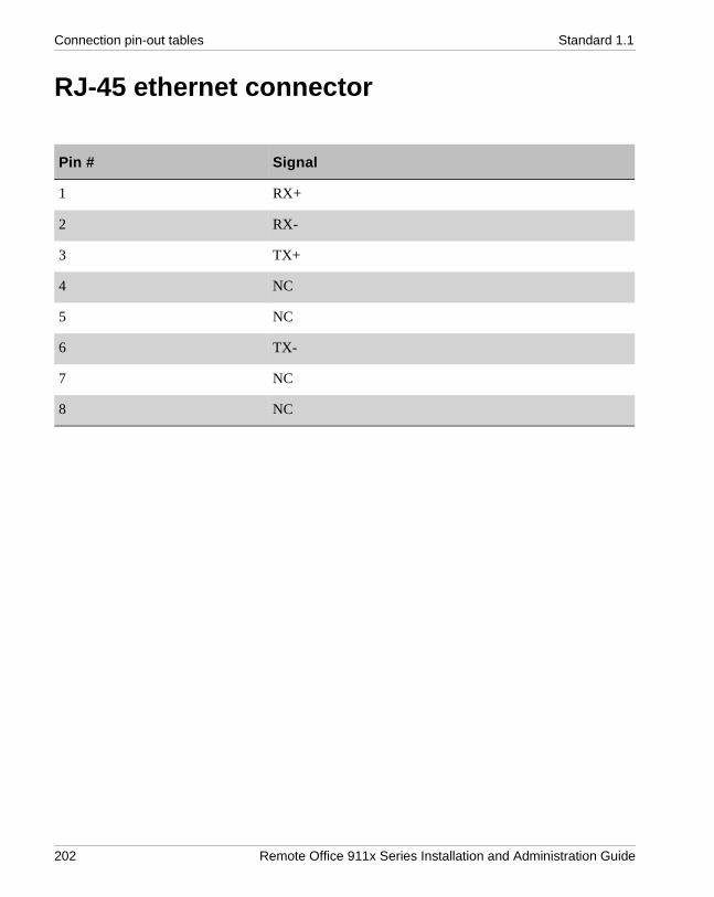
Connection pin-out tables Standard 1.1
RJ-45 ethernet connector
Pin # Signal
1 RX+
2 RX-
3 TX+
4 NC
5 NC
6 TX-
7 NC
8 NC
202 Remote Office 911x Series Installation and Administration Guide

October 2001 Connection pin-out tables
RJ-11 Analog telephone line connector
Pin # Signal
1 NC
2 NC
3 Tip
4 Ring
5 NC
6 NC
Remote Office 911x Series Installation and Administration Guide 203

Connection pin-out tables Standard 1.1
Admin (serial) connector pin-out table
Pin number Signal name I/O Description
1
2 MMI-RXD I MMI RS-232C Receive Data
3 MMI-TXD O MMI RS-232C Transmit Data
4
5 Ground I Logic Ground
6
7
8
9
204 Remote Office 911x Series Installation and Administration Guide
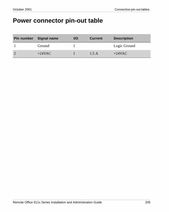
October 2001 Connection pin-out tables
Power connector pin-out table
Pin number Signal name I/O Current Description
1 Ground I Logic Ground
2 +24VAC I 1.5 A +24VAC
Remote Office 911x Series Installation and Administration Guide 205

Connection pin-out tables Standard 1.1
206 Remote Office 911x Series Installation and Administration Guide

A p p e n d i x C
Equipment attachment notices
In this appendix Industry Canada 208
Ringer Equivalence Number 209
Remote Office 911x Series Installation and Administration Guide 207

Equipment attachment notices Standard 1.1
Industry Canada
NOTICE: The Industry Canada label identifies certified equipment. This certification means only that the equipment meets telecommunications network protective, operational, and safety requirements as prescribed in the appropriate Terminal Equipment Technical Requirements document(s). The Department does not guarantee that the equipment operates to the user’s satisfaction.
Before installing this equipment, users should ensure that it is permissible to be connected to the facilities of the local telephone company. The equipment must also be installed using an acceptable method of connection. The customer should be aware that compliance with the above conditions may not prevent degradation of service in some situations.
Repairs to certified equipment should be coordinated by a representative designated by the supplier. Any repairs or alterations made by the user to this equipment, or equipment malfunctions may give the telecommunications company cause to request the user to disconnect the equipment.
Users should ensure for their own protection that the electrical ground connections of the power utility, telephone lines, and internal metallic water pipe system, if present, are connected. This precaution may be particularly important in rural areas.
Caution: Users should not attempt to make such connections themselves, but should contact the appropriate electric inspection authority, or electrician, as appropriate.
208 Remote Office 911x Series Installation and Administration Guide

October 2001 Equipment attachment notices
Ringer Equivalence Number
NOTICE: The Ringer Equivalence Number (REN) assigned to each terminal device provides an indication of the maximum number of terminals allowed to be connected to a telephone interface. The termination on an interface may consist of any combination of devices subject only to the requirement that the sum of the RENs of all devices does not exceed five (5).
For additional information, refer to “Ringer Equivalence Number” on page 217.
Remote Office 911x Series Installation and Administration Guide 209

Equipment attachment notices Standard 1.1
210 Remote Office 911x Series Installation and Administration Guide

A p p e n d i x D
Safety and regulatory information
In this appendix International safety compliance 212
Electromagnetic compatibility 213
Electromagnetic immunity 214
Electrostatic discharge 215
FCC requirements 216
Remote Office 911x Series Installation and Administration Guide 211

Safety and regulatory information Standard 1.1
International safety compliance
The Remote Office 911x series unit and the Remote Office system comply with international safety regulations as listed on this page.
Underwriters Laboratory (UL)
The Remote Office 911x series unit complies with and is listed under UL 1950, Third Edition, including revisions based on the Fourth Amendment to IEC 950, Second Edition.
Canadian Standards Association (CSA)
The Remote Office 911x series unit complies with and is listed under CSA C22.2, No. 950-95.
Europe
The Remote Office 911x series unit complies with and is listed under EN60950: 1992, incorporating amendments 1, 2, 3, 4 & 11.
Australia
The Remote Office 911x series unit complies with and is listed under TS001\AS 3260.
Other Countries Deviations Assessed
Refer to Nemko Test Report # 2000 29173.
212 Remote Office 911x Series Installation and Administration Guide

October 2001 Safety and regulatory information
Electromagnetic compatibility
The Remote Office 911x series unit does not interfere with operation of other licensed communications systems according to the standards set forth by Australia, the United States, and Canada.
The Remote Office 911x series unit does not adversely effect the compliance of the Meridian 1 system to:
! AS 3548 Class B (Australia)! Class A of FCC Part 15, Subpart J! CSPR B requirements.
The margin is at least 2 dB better than the specified limit.
Remote Office 911x Series Installation and Administration Guide 213

Safety and regulatory information Standard 1.1
Electromagnetic immunity
The Remote Office 911x series unit resists electromagnetic interference.
The Remote Office 911x series unit performs correctly when subjected to narrow band radiated fields in frequency range 500 kHz to 1 GHz (field strength up to 10 V/m, 1 kHz, 50% modulated AM signal) per IEC 1000-4-3.
214 Remote Office 911x Series Installation and Administration Guide

October 2001 Safety and regulatory information
Electrostatic discharge
The Remote Office 911x series unit is immune to electrostatic discharges typical for an office environment (carpeted floors, low humidity) according to the test method specified by IEC 1000-4-2.
No damage or malfunction occurs when the Remote Office 911x series unit is exposed to up to +/-8kV of direct discharge. An indirect discharge of up to +/-16 kV does not result in malfunction of the system (to adjacent equipment or connected cabling).
The requirements for both “closed door” and “open door” have been met.
Remote Office 911x Series Installation and Administration Guide 215

Safety and regulatory information Standard 1.1
FCC requirements
Information in the following paragraphs pertains to FCC-required information concerning equipment that is connected to the public switched telephone network (PSTN). These paragraphs describe where to locate details concerning the Remote Office 911x series unit’s compliance to FCC regulations, as well as these regulations’ effects on the use of the Remote Office 911x series unit.
Part 68
The Remote Office 911x series units comply with Part 68 of the FCC rules. A label on the underside of the enclosure contains, among other information, the FCC certification number and ringer equivalence number (REN) for the Remote Office 911x series unit. If requested, you must provide this information to the telephone company.
Class BThis equipment passes tests for compliance with the limits for a Class B digital device, pursuant to part 15 of the FCC Rules. These limits provide reasonable protection against harmful interference in a residential installation. This equipment generates, uses, and can radiate radio frequency energy. If not installed and used in accordance with the instructions, this equipment can cause harmful interference to radio communications. However, there is no guarantee against interference in a particular installation. You can determine whether this equipment causes harmful interference to radio or television reception by turning the equipment off and on. The user can try to correct the interference by one or more of the following measures:
! Reorient or relocate the receiving antenna.! Increase the separation between the equipment and the receiver.! Connect the equipment to an outlet on a circuit different from the outlet that
the receiver connects to when producing the interference.! Consult your Nortel Networks dealer or an experienced radio/TV
technician for help.
Note: Changes or modifications not expressly approved by Nortel Networks can void your right to operate Remote Office 911x series unit equipment.
216 Remote Office 911x Series Installation and Administration Guide

October 2001 Safety and regulatory information
Telephone network plug and jack
The Remote Office 911x series unit’s package contains an FCC-compliant telephone cord and modular plug. The Remote Office 911x series unit’s design calls for it to be connected to the telephone network or premises wiring using a Part 68-compliant modular jack. Refer to Chapter 3, “Installing the Remote Office 911x series unit,” for complete details on proper installation of the Remote Office 911x series unit.
Ringer Equivalence Number
The ringer equivalence number (REN) indicates the number of devices that a telephone line can accommodate. Excessive RENs on the telephone line can result in the devices’ not ringing in response to an incoming call. Typically, the sum of RENs should not exceed five (5.0). To be certain of the number of devices that may be connected to a line, as determined by the total RENs, contact the local telephone company.
This equipment complies with Part 68 of the FCC rules. The information for this equipment is as follows:
Ringer Equivalence: AC-REN - 0.1B and DC-REN - 2.2Grantee’s name: TelStrat, Int’l
Equipment harmful to the telephone network
If the Remote Office 911x series unit causes harm to the telephone network, the telephone company notifies the customer in advance that temporary discontinuance of service may be required. But, if advance notice isn’t practical, the telephone company notifies the customer as soon as possible. The customer also receives notification of their right to file a complaint with the FCC if the customer believes a complaint is necessary.
Party lines
Connection to party line service is subject to state tariffs. Contact the state public utility commission for information.
Remote Office 911x Series Installation and Administration Guide 217

Safety and regulatory information Standard 1.1
218 Remote Office 911x Series Installation and Administration Guide

Glossary
10BaseT Ethernet The Ethernet standard for baseband local area networks using twisted-pair cable carrying 10 megabits per second (Mbps) in a star topology.
A A-lawA companding technique used in encoding and decoding audio signals in 30-channel pulse code modulated (PCM) systems. A-law companding is the primary method used in Europe. See also Mu-law.
adapterHardware required to support a particular device. For example, network adapters provide a port for the network wire. Adapters can be expansion boards or part of the computer’s main circuitry.
administratorA user who is responsible for maintaining the RLC or its associated remote units.
agentA person who is responsible for handling customer calls.
analogThe type of signal used by most telephone connections. A modem converts a digital (computer) signal to analog, and vice versa, so that the signal can travel through telephone lines.
API See application program interface.
applicationA program that runs on a computer.
Remote Office 911x Series Installation and Administration Guide 219

Glossary Standard 1.1
application program interfaceA set of routines, protocols, and tools that programmers use to develop software applications. APIs simplify the development process by providing commonly used programming procedures.
Asynchronous Transfer ModeA network technology that uses start bits and stop bits (identifying the beginning and end of digital code) to facilitate data transfer. ATM equipment can transmit video, audio, and computer data over the same network, ensuring that no single type of data dominates the line.
ATM See Asynchronous Transfer Mode.
Automatic Call Distribution (ACD) applicationsA separate system or built-in feature of a PBX that equally distributes incoming calls to agents. As calls come in, they are placed into a queue (or a waiting line) for the next available agent. The RLC and its associated remote units support all of Nortel Networks’ ACD applications.
B bandwidthThe amount of data that the network can transmit, usually expressed in Mbytes per second.
baseboardSee motherboard.
Basic Input/Output SystemFlash ROM-based code that runs the Power-On Self-Test (POST) and bootstrap loader. BIOS contains low-level access routines for hardware that can be called from DOS.
basic rate interfaceAn ISDN subscriber service that uses two B (64Kbps) channels and one D (64 Kbps) channel to transmit voice, video, and data signals.
220 Remote Office 911x Series Installation and Administration Guide

October 2001 Glossary
BIOSSee Basic Input/Output System.
bitShort for binary digit, the smallest unit of information on a machine. A single bit can hold only one of two values: 0 or 1.
Boolean logicA logic system that enables a computer to use electricity to make complex decisions. The basic logic gates (And, Or, and Not) determine the flow of electricity through the computer’s circuitry and whether specific computing functions are carried out.
booleanA value that can only be true or false.
branch stationA Meridian Digital Telephone set located at the Remote Office 9110, 9115, or 9150 site.
BRISee basic rate interface.
bridgeA protocol-independent device that connects two LANs or two segments of the same LAN. Bridges are faster (and less versatile) than routers because they forward packets without analyzing and rerouting messages.
bridge portBridge ports are configured on the Remote Office 9150 unit and are used to connect branch office trunks through the host PBX to accommodate conference calls, remote station to remote station calls, and so on.
busA collection of wires that connects the microprocessor and main memory to internal computer components. All buses consist of an address bus that transfers data and a data bus that transfers information about where the data should go.
Remote Office 911x Series Installation and Administration Guide 221

Glossary Standard 1.1
In a network, the bus (also called the backbone) is the main cable that connects all devices on a LAN.
byteAbbreviation for binary term, a unit of storage capable of holding a single character. On almost all modern computers, a byte is equal to eight bits. Large amounts of memory are indicated in terms of kilobytes (1024 bytes), megabytes (1 048 576 bytes), and gigabytes (1 073 741 824 bytes).
C cacheA temporary storage area in computer memory.
call duration timerUsed in PSTN mode only, it specifies the minimum length of time that each call to the host PBX remains open, regardless of telephone activity (or lack thereof).
call on demandA call connection that is opened only when a connection to the host PBX is required. This is different from a permanent connection, that is open all the time.
call treatmentA method of handling applied to a call while it is waiting to be answered or serviced.
caller IDCaller ID is used on the RLC to identify the number of the caller requesting access to one of its ports. It is also used on remote units to authenticate incoming calls from the RLC.
calling line identificationAn optional service that identifies the telephone number of the caller. This information can then be used to route the call to the appropriate agent or skillset. The caller’s telephone number can also be displayed on a phoneset.
222 Remote Office 911x Series Installation and Administration Guide

October 2001 Glossary
cardA thin, rectangular plate that chips and other electronic components are placed on. Examples of cards include motherboards, expansion boards, daughterboards, controller boards, network interface cards, and video adapters.
central processing unitThis is the system unit that holds a PC’s essential components.
CBTSee computer-based training.
CD-ROM A type of optical disk capable of storing large amounts of data (up to 1 Gbyte), although the most common size is 630 Mbytes. A single CD-ROM has the storage capacity of 700 floppy disks and is particularly well-suited to information that requires large storage capacity.
chipThe small flake of silicon crystal that makes up the microprocessor. 2. A type of controller.
CLANSee customer local area network.
CLIDSee calling line identification.
clientThe part of a client/server architecture that runs on a personal computer or workstation and relies on a server to perform some operations. For example, an e-mail client is an application that enables you to send and receive e-mail.
CODSee call on demand.
Remote Office 911x Series Installation and Administration Guide 223

Glossary Standard 1.1
codecAn acronym for COder-DECoder. A device that codes analog signals into digital signals for transmission and decodes digital signals into analog signals for receiving.
COM or COMMCommunications port. This usually refers to the Logical Device name of PC serial ports as defined by DOS.
computer-based trainingA type of education that students learn by running special training programs on a computer. CBT is especially effective for training people to use computer applications, because the CBT program can be integrated with the applications.
Configuration ManagerThe software application used to configure and administer remote units and the RLC port that they are connected to.
controller boardA special type of expansion board that contains a controller for a peripheral device. When you attach new devices to a computer, such as a disk drive, often a controller board must also be added.
CPU See central processing unit.
CPU clockThe clock that regulates the execution of instructions inside a computer. See also real-time clock.
crashA serious computer failure whereby the computer stops working or a program closes unexpectedly. A crash indicates a hardware malfunction or a serious software bug.
customer local area networkThe LAN that your corporate services and resources connect to. The RLC and its associated remote units both connect to the CLAN.
224 Remote Office 911x Series Installation and Administration Guide

October 2001 Glossary
D daughterboardUsually used as a synonym for an expansion board, a daughterboard is any printed circuit board that connects directly or indirectly to a motherboard.
DB9 connectorA 9-pin connector labeled ADMIN that provides the RS-232 serial port interface. This serial port connection can be used to configure a Remote Office 9150 unit that is directly connected to a PC.
DB25 connectorThe DB25 connector on the RLC Multi-I/O cable–Enhanced is for future use.
DC See direct current.
DHCPSee dynamic host configuration protocol.
digital linear tapeA high-capacity 1/2-inch streaming tape cartridge format.
digital signal processorA special type of coprocessor that manipulates analog data, such as sound or photographs, that has been converted to digital form.
DIMMSee dual in-line memory module.
direct currentDC, the electrical power used by computers, comes from a single source (such as a battery) that provides a single voltage that stays at a constant level. AC, the power provided by utility companies, must be converted to DC before it can be used in computer systems.
directory number The number that identifies a phoneset on a switch. The directory number (DN) could be a local extension (local DN), a public network telephone number, or an automatic call distribution directory number (ACD-DN).
Remote Office 911x Series Installation and Administration Guide 225

Glossary Standard 1.1
DIP A type of protective packaging for silicon memory chips that provides a safe and convenient means of installing and removing the chip.
DIP switchA series of tiny switches built into circuit boards that enables you to configure a circuit board for a particular type of computer or application. DIP switches are always toggle switches. This means that they have two possible positions: on or off (or 1 or 0).
direct memory accessDMA speeds up system performance by moving blocks of memory around inside the computer (typically between I/O devices and memory). This process enables the microprocessor to spend its time performing other functions.
DLL See dynamic link library.
DLTSee digital linear tape.
DMASee direct memory access.
DNSee directory number.
driverA program that controls a device. Every device, whether it is a printer, disk drive, or keyboard, must have a driver program. A driver acts like a translator between the device and programs that use the device.
DSPSee digital signal processor.
dual in-line memory moduleThe protective packaging for microprocessor chips that provides a safe and convenient means of installing and removing the chip.
226 Remote Office 911x Series Installation and Administration Guide

October 2001 Glossary
dynamic host configuration protocolA protocol for dynamically assigning IP addresses to devices on a network.
dynamic link libraryA library of executable functions or data that can be used by a Windows application. Typically, a DLL provides one or more particular functions and a program accesses the functions by creating either a static or dynamic link to the DLL. A DLL can be used by several applications at the same time.
dynamic port poolA RLC feature that is similar to multiuser ports in that multiple stations can share ports on the RLC. However, users sharing ports from a dynamic pool are assigned to the first available port on the RLC.
E ECCSee error correction code.
ECP See extended capabilities port.
EEPROM See electronically erasable programmable read-only media.
EIDESee enhanced IDE.
EISA See extended industry standard architecture bus.
ELANSee embedded local area network.
electronically erasable programmable read-only mediaA memory chip that needs only a higher than normal voltage and current to erase its contents. An EEPROM chip can be erased and reprogrammed without taking it out of its socket. An EEPROM chip gives a computer and its peripherals a means of storing data without the need for a constant supply of electricity.
Remote Office 911x Series Installation and Administration Guide 227

Glossary Standard 1.1
electrostatic dischargeDischarge of a static charge on a surface or body through a conductive path to ground. Can be damaging to integrated circuits.
embedded local area networkThis is the network connection from the host PBX to the RLC. It is an Ethernet LAN that is segmented from the rest of the Ethernet network and enables signaling and administration access to the RLC. Nortel Networks recommends the following:
! IP traffic should not be routed between the main network and the ELAN.! An IP route should not be established between the two LANs.
Emergency Service NumberThe Remote Office 9150 unit allows you to program an emergency service number (such as 911).
EMIElectro-magnetic interference. Interference in signal transmission or reception caused by the radiation of electrical and magnetic fields.
enhanced IDE An IDE hard disk interface enhanced with hardware and firmware changes to support disks larger than 540 Mbytes, four disks instead of two, and faster transfer rates. See also IDE.
enhanced parallel portA parallel port standard for PCs that supports bidirectional communication between the PC and attached devices (such as a printer).
EPPSee enhanced parallel port.
error correction codeA scheme that can detect and fix single-bit memory errors without crashing the system. Also known as Error Detection and Correction (EDAC).
ESDSee electrostatic discharge.
228 Remote Office 911x Series Installation and Administration Guide

October 2001 Glossary
EthernetA widely used LAN protocol that uses a bus topology and supports data transfer rates of 10 Mbps.
eventAn occurrence or action on the RLC or remote unit, such as the sending or receiving of a message, the opening or closing of an application, or the reporting of an error. Some events are for information only, while others can indicate a problem.
expansion boardAny board that plugs in to one of the computer’s expansion slots. Expansion boards include controller boards, LAN cards, and video adapters.
expansion busEnables expansion boards to access the microprocessor and memory. See also bus.
expressionA building block of a script, used to test for conditions, perform calculations, or compare values within scripts. See also logical expression, mathematical expressions, and relational expression.
extended capabilities portA parallel-port standard for PCs that supports bidirectional communication between the PC and attached devices (such as a printer).
extended industry standard architecture busA 32-bit bus that accommodates ISA PC boards.
F first-level thresholdThe value that represents the lowest value of the normal range for a given field in a threshold class. The system tracks how often the value for the field falls below this value.
Remote Office 911x Series Installation and Administration Guide 229

Glossary Standard 1.1
G G.711G.711 is the international standard for encoding telephone audio on a 64 Kbps channel. It is a pulse code modulation (PCM) scheme operating at an 8 kHz sample rate, with 8 bits per sample. According to the Nyquist theorem, that states that a signal must be sampled at twice its highest frequency component, G.711 can encode frequencies between 0 and 4 kHz. Telcos can select between two different variants of G.711: A-law and mµ-law. A-law is the standard for international circuits.
G.726G.726 is a standard ADPCM algorithm specified by the International Telecommunication Union (ITU) for reducing the 64 kbps A-Law or mµ-law logarithmic data of a normal telephone line to 16, 24, 32, or 40 kbps.
G.729G.729 is a voice compression International Telecommunications Union (ITU) standard that can be used in a wide range of applications including wireless communications, digital satellite systems, packetized speech, and digital leased lines. G.729 provides 8 Kbps bandwidth for compressed speech at toll quality (equivalent to G.726 32 Kbps ADPCM under clean channel condition).
gatewayA device that functions as a node on two or more networks, forwarding packets from one network to addresses in the other networks. In a Remote Office context, the gateway is the device on the network that directs traffic to and from the Remote Office 9150 unit or RLC.
GbyteSee gigabyte.
general protection faultA computer condition that causes a Windows application to crash. GPFs usually occur when one application attempts to use memory assigned to another application.
gigabyte1 073 741 824 bytes. One Gbyte is equal to 1024 Mbytes.
230 Remote Office 911x Series Installation and Administration Guide

October 2001 Glossary
GPCPGeneral purpose computing platform
GPF See general protection fault.
graphical user interfaceThe information displayed on the monitor when a Windows application (or another non-command-based application) runs. A graphical user interface uses features such as pointers, icons, I-beams, and menus to make the program easier to use.
GUI See graphical user interface.
H handshakingA process involved in establishing a valid connection or signal between two pieces of hardware or communications software.
host call appearance keyAn assigned key on the telephone set at the remote site that is used to establish a connection with the host PBX or to receive incoming calls from the host PBX.
host-controlled call modeWhen a call is placed to someone at the host site, or when someone from the host site calls the remote site, the call is in host-controlled call mode. Calls in host-controlled mode are routed through the host PBX.
host stationA telephone set located at the host PBX site.
host trunkThe ISDN PRI or TI connection located at the host site. Host trunks are used to route calls from the host PBX to remote sites over the PSTN.
Remote Office 911x Series Installation and Administration Guide 231

Glossary Standard 1.1
hubA common connection point for all 10BaseT cables connected to a small network. A hub enables data to go from one device to another.
I iconA small picture that represents an object or program in a graphical user interface.
IDECommonly used to describe the AT attachment design, the dominant hard disk interface. IDE is a cost-effective interface technology for mass storage devices that the controller is integrated into the disk or CD-ROM drive in.
idle timerIdentifies the maximum length of time that an ISDN connection should remain idle before it can be closed. Idle means that a voice connection does not exist, and buttons are not being pressed on the digital telephone.
Industry Standard ArchitectureA 16-bit standard interface for add-in cards.
input/outputRefers to any operation, program, or device that enters data into a computer or extracts data from a computer.
integrated services digital networkA worldwide digital communication protocol that permits telephone networks to carry data, voice, and other source material. There are two kinds of ISDN lines—Primary Rate Interface (PRI) and Basic Rate Interface (BRI). See also BRI.
internet protocolThe protocol within TCP/IP that governs the breakup of data messages into packets, the routing of the packets from sender to destination network, and the reassembly of the packets into the original data messages at the destination.
I/O See input/output.
232 Remote Office 911x Series Installation and Administration Guide

October 2001 Glossary
IPSee internet protocol.
IP addressInternet Protocol address. An identifier for a computer or device on a TCP/IP network. Networks use the TCP/IP protocol to route messages based on the IP address of the destination. The format of an IP address is a 32-bit numeric address written as four numbers separated by periods. Each number can be 0–255. For example, 1.160.10.240 could be an IP address.
IPXInternetwork Packet Exchange. A networking protocol used by the Novell NetWare operating systems.
ISASee Industry Standard Architecture.
ISDNSee integrated services digital network.
J jumperA metal bridge that closes an electrical circuit. Typically, a jumper consists of a plastic plug that fits over a pair of protruding pins. Jumpers are sometimes used to configure expansion boards. By placing a jumper plug over a different set of pins, you can change a board’s parameters.
K KbyteSee kilobyte.
kilobyte1024 bytes. Roughly the amount of information in half a typewritten page.
L LANSee local area network.
Remote Office 911x Series Installation and Administration Guide 233
Glossary Standard 1.1
LCDLiquid crystal display. An alphanumeric display using liquid crystal sealed between two pieces of glass.
LEDLight emitting diode. A semiconductor diode that emits light when a current is passed through it.
local area networkA computer network that spans a relatively small area. Most LANs connect workstations and personal computers and are confined to a single building or group of buildings.
local callA call that originates at your site.
local call appearance keyAn assigned key on the telephone set at the remote site that is used to call another station at the branch office, or to place and receive calls through the local PSTN.
local stationA telephone set located at a remote site.
locally controlled call modeWhen you place a call from a specified local call appearance key, or your call is to another telephone at your branch site, you are in locally controlled call mode. Calls in locally controlled mode are routed through the local PSTN.
logical expressionA symbol used in scripts to test for different conditions. Logical expressions are AND, OR, and NOT. See also mathematical expressions and relational expression.
M M1Meridian 1 PBX
234 Remote Office 911x Series Installation and Administration Guide

October 2001 Glossary
MATMeridian Administration Tools. This is a Nortel Networks software application that is used to administer the Meridian 1 PBX.
mathematical expressionsThe expressions used in scripts to add, subtract, multiply, and divide values. Mathematical expressions are addition (+), subtraction (-), division (/), and multiplication (*). See also logical expression, relational expression.
MbyteSee megabyte.
megabyteA unit of measurement for data storage equal to 1 048 576 bytes.
megahertz One million cycles per second.
MHzSee megahertz.
RLCAn abbreviation for Reach Line Card. The RLC is installed on the host PBX and relays voice and signaling information from the digital telephones connected at a remote site to the host PBX.
motherboardThe principal board that has connectors for attaching devices to the bus. Typically, the motherboard contains the CPU, memory, and basic controllers for the system. On PCs, the motherboard is often called the system board.
MTBFMean time between failures.
Mu-lawA companding method for encoding and decoding audio signals in 24-channel pulse-code-modulated (PCM) systems. Mu-law is the method used in North America and Japan See also A-law.
Remote Office 911x Series Installation and Administration Guide 235

Glossary Standard 1.1
multiuser portsA Remote Office 9150 unit port feature that allows multiple stations to time-share a single port on the host PBX. All stations that use a multiuser port are always assigned to the same port number (TN) on the host PBX.
N NetBeuiSee NetBIOS enhanced user interface.
NetBIOSSee Network Basic Input Output System.
NetBIOS enhanced user interfaceAn enhanced version of the NetBIOS protocol used by network operating systems such as LAN Manager, LAN Server, Windows for Workgroups, Windows 95 and Windows NT.
Network Basic Input Output SystemAn application programming interface (API) that augments the DOS BIOS by adding special functions for local-area networks (LANs). Almost all LANs for PCs are based on the NetBIOS. Some LAN manufacturers have even extended it, adding additional network capabilities.
network interface card An expansion board that enables a PC to be connected to a local area network (LAN).
NICSee network interface card.
nodeA device connected to the network capable of connecting to other network devices. For example, the RLC and each remote unit are nodes on the network.
NPASee Number Plan Area.
236 Remote Office 911x Series Installation and Administration Guide

October 2001 Glossary
Number Plan AreaArea code
NVRAMNon-Volatile Random Access Memory. RAM that doesn’t lose its memory when you shut the electricity off to it.
O OA&MOperations, administration, and maintenance
object linking and embeddingA compound document standard that enables you to create objects with one application and then link or embed them in a second application.
ODBCSee Open Database Connectivity.
OEMOriginal Equipment Manufacturer. The maker of equipment marketed by another vendor, usually under the name of the reseller. The OEM may only manufacture certain components, or complete computers, that are then often configured with software and/or other hardware, by the reseller.
OLESee object linking and embedding.
online/offline tableThe online/offline table is configured on the RLC. It allows you to schedule times that the host PBX connection is made available to the remote site and the times all telephones at the remote site can use only the local telephone service.
The online/offline table is used for controlling ISDN BRI costs.
Open Database ConnectivityA Microsoft-defined database application program interface (API) standard.
Remote Office 911x Series Installation and Administration Guide 237

Glossary Standard 1.1
Open System InterconnectionA worldwide communications standard that defines a framework for implementing protocols in seven layers.
OSOperating Standard
OSISee Open System Interconnection.
P packetized voiceDigital signal processors (DSPs), located in the Remote Office 9150 unit and RLC, convert analog voice into digital data. The data is constructed as a UDP/IP voice packet for transmission over an IP network.
parityThe quality of being either odd or even. The fact that all numbers have parity is commonly used in data communications to ensure the validity of data.
parallel portA type of interface used to connect an external device such as a printer to a PC. Most personal computers have both a parallel port and at least one serial port.
PBXSee private branch exchange.
PCPersonal computer. A computer with an architecture that is compatible with the IBM PC.
peggingThe action of incrementing statistical counters to track system events.
pegging thresholdA threshold used to define a cut-off value for statistics such as short call and service level. Pegging thresholds are used in reports and historical statistics.
238 Remote Office 911x Series Installation and Administration Guide

October 2001 Glossary
personal directory numberA DN that an agent can be reached directly on, usually for private calls.
phonesetThe physical device, connected to the switch, calls are presented to.
PINGPacket Internet Groper. A protocol that can be used to test the Ethernet connection to devices on the network (such as the RLC and its associated remote units).
position IDA unique identifier for a phoneset, used by the switch to route calls to the phoneset.
POSTSee power-on self-test.
power-on self-test Initializes and performs rudimentary tests on baseboard hardware, including CPU, floating point unit, interrupts, memory, real-time clock, video, and auto-initializing PCI and EISA bus.
priority DNA user station can be configured as a priority DN. There are two levels of priority—high and normal. High priority level allows you to
! ensure a trunk is always available! use PSTN trunking for the host PBX connections! move the high priority DN first from the IP network to the PSTN
private branch exchangeA telephone switch, typically used by a business to service its internal telephone needs. A PBX usually offers more advanced features than are generally available on the public network. Users of the PBX share a certain number of outside lines for placing telephone calls external to the PBX.
Remote Office 911x Series Installation and Administration Guide 239

Glossary Standard 1.1
protocolA standard format used for communication between two devices. The protocol determines the type of error checking to be used, the data compression method (if any), how the sending device will indicate that it has finished sending a message, and how the receiving device will indicate that it has received a message.
PSTNSee public switched telephone network.
public switched telephone networkAny common carrier network that provides circuit switching between public users. The term is usually applied to the public telephone network.
Q QoS Transitioning TechnologyNortel Networks’ patented technology that can automatically switch calls from the IP network to the PSTN when the voice Quality of Service falls below a predetermined threshold, and back to the IP network when the Quality of Service returns to normal.
R RAMRandom Access Memory. This is the most common type of memory found in computers and other devices, such as printers. The term RAM is usually synonymous with main memory, the memory available to programs. For example, a computer with 8 Mbytes of RAM has approximately 8 million bytes of memory that programs can use.
RASRemote Access Server. A host on the local area network that is equipped with modems to enable users to connect to the network over telephone lines.
real-time clockA clock that keeps track of the time even when the computer is turned off. See also CPU clock.
240 Remote Office 911x Series Installation and Administration Guide

October 2001 Glossary
recorded announcement routeA resource installed on the switch that offers a recorded announcement to callers.
relational expressionAn expression used in scripts to test for different conditions. Relational expressions are less than (<), greater than (>), less than or equal (< =), greater than or equal (> =), and not equal (< >). See also logical expression and mathematical expressions.
Remote Access ServicesA feature built into Windows NT and Windows 95 that enables users to log in to an NT-based LAN using a modem, X.25 connection, or WAN link. Also known as Dial Up Networking.
remote stationA telephone set located at the Remote Office 9150 or Remote Office 911x series site.
remote trunkFrom the RLC’s point of view, remote trunks are the ISDN BRI connections between the PSTN and the remote unit located at the branch office site.
RJ-11 ConnectorA six-conductor modular jack that is typically wired for four conductors. The RJ-11 jack is the most common telephone jack in the entire world.
RJ-45 ConnectorAn eight position, eight conductor modular jack used for data transmission over a standard telephone wire. The RJ-45 jack provides the 10BaseT Ethernet connection.
ROMRead-Only Memory. This is the computer memory that data has been prerecorded on and cannot be removed from.
Remote Office 911x Series Installation and Administration Guide 241

Glossary Standard 1.1
routerA device that connects two LANs. Routers are similar to bridges but provide additional functionality, such as the ability to filter messages and forward them to different places based on various criteria.
RTCSee real-time clock.
S SCASee single connector architecture.
second-level thresholdThe value used in display thresholds that represents the highest value of the normal range for a given statistic.
security identifierThe remote unit sends the branch office security identifier (password) to the RLC for each connection request. The RLC matches the identifier configured for the RLC port. When it finds a match, it grants access to the port and allows the call to proceed.
sequenced packet exchangeA transport layer protocol (layer 4 of the OSI Model) used in Novell Netware networks. The SPX layer sits on top of the IPX layer (layer 3) and provides connection-oriented services between two nodes on the network. SPX is used primarily by client/server applications.
serial portA general-purpose interface that can be used for almost any type of device, including modems, mice, and printers (although most printers are connected to a parallel port). Most serial ports on personal computers conform to the RS-232C or RS-422 standards.
serverA computer or device on a network that manages network resources. Examples of servers include file servers, print servers, network servers, and database servers.
242 Remote Office 911x Series Installation and Administration Guide

October 2001 Glossary
serviceA process that adheres to a Windows NT structure and requirements. A service provides system functionality.
Service Control ManagerA Windows NT process that manages the different services on the PC.
service profile identifierWhen you order an ISDN line, your phone company provides you with a SPID for every phone number you have.
silence suppressionA feature that prevents packet transmission during periods when there is no voice data present.
SIMMSingle In-line Memory Module. Used on Macs and PCs. A form of chip packaging where leads (pins) are arranged in a single row protruding from the chip.
simple network management protocol A set of protocols for managing complex networks. SNMP works by sending messages, called protocol data units (PDUs), to different parts of a network and then analyzing the responses.
single connector architecture A method for supplying power and data lines in one connector on hard disks. Provides hot-swap capability.
single-user portsA RLC port that supports one remote station.
Small Computer System Interface A standard for connecting and controlling mass storage devices such as CD-ROMS, tape drives, and hard disks.
SNMPSee simple network management protocol.
Remote Office 911x Series Installation and Administration Guide 243

Glossary Standard 1.1
SPIDSee service profile identifier.
SPRE codeA Special Prefix code that is used to initiate use of a host PBX feature. In a Remote Office context, SPRE codes are used to
! toggle a remote site between online and offline modes! use the paging feature! switch an analog or ATA equipped station from host-controlled mode to
locally controlled mode so that local calls can be made! register a Remote Office 9150 unit for a multiuser or dynamic port
SPXSee sequenced packet exchange.
SRAMStatic Random Access Memory. A form of RAM that retains its data without the constant refreshing that DRAM requires.
stationA telephone or fax machine located at a remote site.
stop bitIn asynchronous communications, a bit that indicates a byte has just been transmitted. Every byte of data is preceded by a start bit and followed by a stop bit.
subnet maskA subnet mask is the part of the IP address used to represent a subnetwork within a network. A typical IP address might be 192.210.34.144. Each part of this address is made up of eight bits. The subnet mask identifies to the RLC or remote unit what portion of the IP address represents the network (and subnetwork) and what portion represents the host.
SVGASuper Video Graphics Adapter. An extension of the VGA video standard.
244 Remote Office 911x Series Installation and Administration Guide

October 2001 Glossary
switchIn a telecommunications network, a switch is the hardware that receives phone calls and provides connections to telephone sets. The switch allows a connection to be established as necessary and terminated when there is no longer a session to support it.
In networks, a device that filters and forwards packets between LAN segments. Switches operate at the data link layer (layer 2) of the OSI Reference Model and therefore support any packet protocol. LANs that use switches to join segments are called switched LANs or, in the case of Ethernet networks, switched Ethernet LANs.
switch resourceA device that is configured on the switch.
T TAPISee telephone application programming interface.
TCP/IPTransport Control Protocol/Internet Protocol. The communication protocol used to connect devices on the Internet. TCP/IP is the standard for transmitting data over networks.
telephone application programming interfaceA term that refers to the Windows Telephony API. TAPI is a changing (i.e. improving) set of functions supported by Windows that allow Windows applications to program telephone-line based devices such as single and multi-line phones (both digital and analog), modems and fax machines in a device-independent manner.
telephonyThe science of translating sound into electrical signals, transmitting them, and then converting them back to sound. The term is used frequently to refer to computer hardware and software that perform functions traditionally performed by telephone equipment.
TFTPSee trivial file transfer protocol.
Remote Office 911x Series Installation and Administration Guide 245

Glossary Standard 1.1
thresholdA value for a statistic that system handling of the statistic changes at.
threshold classA set of options that specifies how statistics are treated in reports and real-time displays. See also pegging threshold.
Token RingA PC network protocol developed by IBM. A Token Ring network is a type of computer network whereby all the computers are arranged schematically in a circle.
trivial file transfer protocolA simplified version of FTP that transfers files but does not provide password protection or user-directory capability. It is associated with the TCP/IP family of protocols. TFTP depends on the connectionless datagram delivery service, UDP.
trunkA communications link between a PBX and the public central office, or between PBXs. Various trunk types provide services such as Direct Inward Dialing (DID), ISDN, and central office connectivity.
trunk access digitsTrunk access digits are numbers that are used by the remote unit to determine the trunk to use when routing a call. For example, 9 is a common trunk access digit used to obtain an outside line.
trunk groupsA trunk group consists of one or more trunk lines that are logically grouped. You can configure up to eight trunk groups on the Remote Office 9150 unit.
trunk interface modulesUsed to route calls over the PSTN. The number of modules you must install on the Remote Office 9150 unit depends on the number of simultaneous calls you want in host-controlled or locally controlled mode.
246 Remote Office 911x Series Installation and Administration Guide

October 2001 Glossary
U uninterruptible power supplyA power supply that includes a battery to maintain power in the event of a power outage. Typically, a UPS keeps a computer running for several minutes after a power outage, enabling you to save data that is in RAM and to shut down the computer safely.
UPSSee uninterruptible power supply.
utilityA program that performs a specific task, usually related to managing system resources. Operating systems contain a number of utilities for managing disk drives, printers, and other devices.
V V.35An ITU-T standard describing a synchronous, physical layer protocol used for communications between a network access device and a packet network. V.35 is most commonly used in the United States and in Europe, and is recommended for speeds up to 48 Kbps. In practice, V.35 is used for synchronous transmission up to 2.048 Mbps.
V.35 interfaceA Frame Relay network technology used to carry the voice conversation and telephone set control signals over:
! a Frame Relay Access Device to send the voice and signal packets to the Remote Office 9150 unit via a Frame Relay Network
! a Channel Service Unit/Data Service Unit (CSU/DSU) to access a switched 56K line service
voice compressionPrior to transmission, the voice data is compressed; after transmission, the data is converted back to voice data at the destination. Voice compression means that voice consumes less bandwidth, leaving more bandwidth for data or other voice or fax communications.
Remote Office 911x Series Installation and Administration Guide 247

Glossary Standard 1.1
voice jitter attenuationA feature that removes the variable delays from the voice packets sent across the IP network, thus avoiding awkward-sounding speech.
Voice over Internet Protocol (VoIP)Technology that uses the IP data network to carry the voice conversation and telephone set control signals between a remote site and the host PBX.
W WANWide area network. A computer network that spans a relatively large geographical area. Typically, a WAN consists of two or more local area networks (LANs). The largest WAN in existence is the Internet.
248 Remote Office 911x Series Installation and Administration Guide

Fields index
Symbols802.1p Mapping 106
AAddon Module Type 103Address Information
IP Address 106IP Gateway 106IP Network Mask 106
Analog Localization 103Autohold 103Automatic DHCP Configuration 106Available Flex Channels 154Available MIPS 153Available Voice Channels 153, 154
BBandwidth (BW) Connection Statistics
IP QoS Status 147No of Voice Calls on IP 147No of Voice Calls on PSTN 147Remote Unit Number 147Signaling Status 147Total Up Trunk BW 147Used IP BW 147Used Trunk BW 147
BroadCast Packet 161Browse
Upload Configuration 135Browse (button)
Software Upload 169
CCall BW 150Call Type 144Called Number 144Caller Info Statistics
Call BW 150Connection ID 150Current Media 150Last Transition to IP 150Last Transition to PSTN 150Priority 150Remote ID 150Start Time 150Transitions to IP 150Transitions to PSTN 150Type 150
Close Time 144Connection ID 150Current Media 150
DDevice Number 153DiffServ CodePoint 106DSP Gain 101DSP Statistics
Total Voice Channels 153DSP statistics
Available Flex Channels 154Available MIPS 153Available Voice Channels 153, 154Device Number 153In Service 153Module Number 153Name 154Single Dig Dev ID 153
Remote Office 911x Series Installation and Administration Guide 249

Fields Index Standard 1.1
Total Channels 153Total Flex Channels 154Total MIPS 153Total Modem Channels 153Total Reserved Channels 154Total Tones Channels 154
Duration 144
EEmergency Activation Code 101Error % 161Ethernet Interface Statistics
UPkts 157
HHour 161
IIn Service 153Inbound Security ID 110IP Address 106
Software Upload 168Upload Configuration 134
IP Connection 109IP Address 109IP Signaling 109
IP Gateway 106IP Network Mask 106IP QoS Status 147
LLast Transition to IP 150Last Transition to PSTN 150Local Call
Autohold 103Local Calling Key Position 103
Status 102Local DN 103
MMessages 140Modem Tones 103Module Number 153
NName 154Network statistics
BroadCast Packet 161Error % 161Hour 161Rx DiscPkt 161Rx Dropped 161Rx Error 161Rx Frames 161Rx MultiPkt 161Rx UCastPkt 161Tx DiscPkt 161Tx Frames 161Tx UCastPkt 161
No of Voice Calls on IP 147No of Voice Calls on PSTN 147Node Name 101
OOutbound Security ID 110
PPhone Type 103Priority 150PSTN Connection 109
PSTN Number to Connect to RLC 110
250 Remote Office 911x SeriesInstallation and Administration Guide

October 2001 Fields Index
Rregistration 102Remote ID 144, 150Remote Unit Number 147Resize Logs
Messages 140RLC Port Number 109Rx DiscPkt 161Rx Dropped 161Rx Error 161Rx Frames 161Rx MultiPkt 161Rx UCastPkt 161
SSecurity ID
Inbound Security ID 110Outbound Security ID 110
Security Level 110Signaling Status 147Single Dig Dev ID 153SPRE Codes
DeRegistration 102Offline 102Online 102registration 102
Start Time 144, 150statistics
Bandwidth (BW) Connection StatisticsIP QoS Status 147No of Voice Calls on IP 147No of Voice Calls on PSTN 147Remote Unit Number 147Signaling Status 147Total Up Trunk BW 147Used IP BW 147Used Trunk BW 147
Caller Info StatisticsCall BW 150Connection ID 150
Current Media 150Last Transition to IP 150Last Transition to PSTN 150Priority 150Remote ID 150Start Time 150Transitions to IP 150Transitions to PSTN 150Type 150
Caller Info Statistics field descriptions 150DSP statistics
Available Flex Channels 154Available MIPS 153Available Voice Channels 153, 154Device Number 153In Service 153Module Number 153Name 154Single Dig Dev ID 153Total Channels 153Total Flex Channels 154Total MIPS 153Total Modem Channels 153Total Reserved Channels 154Total Tones Channels 154Total Voice Channels 153
Ethernet Interface StatisticsUPkts 157
Network statisticsBroadCast Packet 161Error % 161Hour 161Rx DiscPkt 161Rx Dropped 161Rx Error 161Rx Frames 161Rx MultiPkt 161Rx UCastPkt 161Tx DiscPkt 161Tx Frames 161Tx UCastPkt 161
Resize Logs
Remote Office 911x SeriesInstallation and Administration Guide 251

Fields Index Standard 1.1
Messages 140Trunk Connection Statistics
Call Type 144Called Number 144Close Time 144Duration 144Remote ID 144Start Time 144Status 144Trunk Number 144
Status 144
TTime Offset 101Total Channels 153Total Flex Channels 154Total MIPS 153Total Modem Channels 153Total Reserved Channels 154Total Tones Channels 154Total Up Trunk BW 147Total Voice Channels 153
Transitions to IP 150Transitions to PSTN 150Trunk Connection Statistics
Call Type 144Called Number 144Close Time 144Duration 144Remote ID 144Start Time 144Status 144Trunk Number 144
Trunk Number 144Tx DiscPkt 161Tx Frames 161Tx UCastPkt 161Type 150
UUnit ID 101, 109UPkts 157Used IP BW 147Used Trunk BW 147
252 Remote Office 911x SeriesInstallation and Administration Guide

Index
Numerics10BaseT Ethernet
connection options 11description 2
9110Refer to Remote Office 9110
9115Refer to Remote Office 9115
911xRefer to Remote Office 911x series
AACD features
featuresACD features 23
Admin 157Admin connector 204analog
connection options 11Automatic Call Distribution (ACD)
applications 24
Bbackup
creating a backup configuration file 131introduction 130restoring the configuration 133storing configuration files 130
bandwidthmeasuring with Bandwidth Connection
Statistics 145Bandwidth Connection Statistics screen 145bandwidth limit 116
display message 121
Ccable connections 7cable connectors
RJ-11 7RJ-45 7
cable modem 10cables
included 36not included 36
cablingcables included with the Remote Office 9110
unit 36cables you must supply 36
call forward 124call forward feature 23, 124call modes
host-controlled 13locally controlled 13
call timershow they work 27idle timer 26introduction 26minimum call duration timer 26
call transfer 124call waiting 23, 123
host-controlled mode 123locally controlled mode 123
call waiting featurefeatures
call waiting 23Caller Information Statistics
displaying 149Caller Information Statistics screen 148
QoS Transitioning Technology 148calls
call forward feature 124call transfer feature 124call waiting feature 123
Remote Office 911x Series Installation and Administration Guide 253

Index Standard 1.1
calling another station at your site 117conference feature 124display messages 120emergency service calls feature 122hold feature 122host-controlled indicator updates 118host-controlled mode 112incoming 13locally controlled indicator updates 118locally controlled mode 112methods for placing outgoing calls 115offline mode 113online mode 113online/offline modes
putting unit in online mode 125outgoing 13placing a host-controlled call 116
bandwidth limit 116DSP limit 116
placing a locally controlled call 117placing calls 115receiving calls 115
Canadian Standards AssociationCSA C22.2, No 950 212
Canadian Standards Association (CSA) 212Channel 157CLASS 46computer telephony integration applications 23conference 124conference feature 23, 124configuration
default valuesrestoring 70, 71
deregistration SPRE code 78emergency code 74IP information 69offline SPRE code 76online SPRE code 75registration SPRE code 77telephone menu 69
default password 69display local IP 69modify deregistration SPRE code 78modify emergency code 74modify offline SPRE code 76modify online SPRE code 75
modify registration SPRE code 77modify unit ID 72restore default values 70, 71time offset 73user name 69
time offset 73unit ID 72
Configuration ManagerHelp
Display Logs definitions 187configuring the unit using the telephone menu
accessing the telephone menu 67before you begin 69information you need 66running the telephone menu script 69telephone menu key function 67
configuring the unit with Configuration Manager
IP addressesconfiguring 104
RLC connection informationconfiguring 107
system settingsconfiguring 99field descriptions 101system identification information 98
connection options10BaseT Ethernet 11administration PC 37introduction 11PSTN 11Quality of Service transitioning technology 11
CSA C22.2, No. 950 212
DDB-9 connector
Remote Office 9115 7deployment
IP options 43on-demand 43permanent 43
local PSTN connectionemergency service calls 45inbound local calls and RLC calls 46
254 Remote Office 911x Series Installation and Administration Guide

October 2001 Index
CLASS 46distinctive ring 46
model 3 - PSTN permanent 46model 4 - PSTN on-demand 46model 5 - IP permanent/PSTN permanent
47models 1 and 2 - IP only 46outbound local calls 45
media 42NAT 42PNAT 42PSTN options 44
on-demand 44permanent 44
QoSIP permanent, PSTN permanent 45
QoS transition 44shared PSTN numbers
RLC calling shared PSTN number 47transport media
IP 42PSTN 42QoS Transitioning Technology 42
deployment optionsintroduction 42
deregistration 102SPRE code 78
digital telephonesdisplay messages
introduction 120message descriptions 120
going online and offlineintroduction 125overriding an automatic offline event 126using the SPRE code for online mode 125
indicator updateshost-controlled indicator updates 118introduction 118locally controlled indicator updates 118
modes of operationcontrolling online and offline modes 114host-controlled mode 112host-controlled vs locally controlled modes
113introduction 112locally controlled mode 112
offline mode 113online mode 113why offline is important 114
placing and receiving callscalling another station at your site 117introduction 115methods for placing outgoing calls 115placing host-controlled calls 116
supported sets 22telephone features
call forward 124conference 124introduction 122
troubleshooting 177Disc 157, 158Display Logs
definitions 187display messages
bandwidth limit 121going offline 120hostless mode 120offline mode 120online mode 121port already in use 121port not logged in 121release and try again 121
distinctive ring 46documents
related xxiiDSP
DSP Statistics screen 151DSP application modules
Hardware Statistics 151, 155DSP limit 116
display messagedisplay messages
DSP limit 121DSP Statistics screen 151
Eelectromagnetic compatibility 213
AS 3548 Class B (Australia) 213Class A of FCC Part 15, Subpart J 213CSPR B requirements 213
Remote Office 911x SeriesInstallation and Administration Guide 255

Index Standard 1.1
margin 213electromagnetic immunity 214electrostatic discharge 215emergency
service number description 30emergency calls
placing 122emergency code 74emergency service calls 45, 122emergency service calls feature 122EN90650 212equipment
equipment attachment notices 207equipment attachment notices 207
Industry Canada 208Ringer Equivalence Number 209
Err 157, 158Ethernet
Ethernet Interface Statistics screen 155Ethernet Interface Statistics
Admin 157Channel 157Disc 157, 158Err 157, 158Ifc Type 157IfcNo 157In - Octet 157LAN Drv 157MPkts 157, 158MTU Len 157Oper 157Out - Octet 157QLen 158Speed 157UPkts 157
Ethernet Interface Statistics screen 155extracting upgrade files from the download file
165
Ffeatures
call forward 23, 124call transfer 124call waiting 23, 123
host-controlled mode 123locally controlled mode 123
conference 23, 124hold 23transfer 23
firmwareextracting upgrade files 165upgrade
downloading files 164performing 167
Ggoing offline
display message 120
HHardware Statistics
introduction 151, 155Help
Display Logs definitions 187hold 23, 122hold feature 23host call appearance key
purpose 13host-controlled calls
placing 116bandwidth limit 116DSP limit 116
host-controlled modeindicator updates 118overview 112
hostless modedisplay message 120
Iidle timer 26, 27Ifc Type 157IfcNo 157In - Octet 157inbound local calls and RLC calls 46
CLASS 46
256 Remote Office 911x Series Installation and Administration Guide

October 2001 Index
distinctive ring 46incoming calls 13Industry Canada notice 208installation
9110 circuit cardpowering up 57
9110 unitconnecting 56removing the base of the digital telephone
529115 unit
powering up 62general safety 50unpacking and inspecting the equipment 51
international safety compliance 212Australia 212Canadian Standards Association 212EN90650 212Underwriters Laboratory (UL) 212
Internet Access Devicedescription 10
IP 42addressing and routing 40PSTN and IP network diagram 12remote unit 69
IP deployment 43IP on-demand 43IP permanent 43
IP on-demand 43IP permanent 43IP permanent, PSTN permanent 45ISDN Basic Rate Interface (BRI) router 10
LLAN Drv 157LEDs
description 5Remote Office 911x unit LED display
diagrams 6troubleshooting 176
local call appearance keypurpose 13
local callinglocal calls through PSTN 28
telephone featuressupported 28
local PSTN connectionemergency service calls 45inbound local calls and RLC calls 46
CLASS 46distinctive ring 46
model 3 - PSTN permanent 46model 4 - PSTN on-demand 46model 5 - IP permanent/PSTN permanent 47models 1 and 2 - IP only 46outbound local calls 45
locally controlled call mode 13calling another station 117indicator updates 118
locally controlled callsplacing 117
locally controlled modeoverview 112
logsclearing
introduction 141displaying
introduction 138viewing 138
Mmedia 42Meridian Communication Adapters (MCA) 23minimum call duration timer 26model 3 - PSTN permanent 46model 4 - PSTN on-demand 46model 5 - IP permanent/PSTN permanent 47models 1 and 2 - IP only 46mounting options
Remote Office 9115 36MPkts 157, 158MTU Len 157
NNAT 42network address translation (NAT) 42network considerations
Remote Office 911x SeriesInstallation and Administration Guide 257

Index Standard 1.1
introduction 40IP addressing and routing 40quality of service 41
no security 21notices
equipment attachment 207Industry Canada 208Ringer Equivalence Number 209
Ooffline 102offline mode
display message 120offline SPRE code 76online 102online mode
display message 121online SPRE code 75online/offline table
configuration 29how the table works 29introduction 29offline mode 113online mode 113why offline is important 114
Oper 157Out - Octet 157outbound local calls 45outgoing calls 13
Ppassword
Configuration Manager password 128default 69Remote Office 911x series password 128
PC administrationadministering multiple nodes 38connection options 37Ethernet connection 37
PC requirements 38PING
using 188pin-out tables
connectorAdmin 204Power 205
RJ11 Analog telephone line connector 203RJ-45 ethernet connector 202
placing calls 115host-controlled 116
bandwidth limit 116DSP limit 116
locally controlled 117PNAT 42port already in use
display message 121port not logged in
display message 121port number and network address translation
(PNAT) 42Power
connector 205power requirements
Remote Office 911x units 32preinstallation preparation
unpacking and inspection 51PSTN 42PSTN deployment 44
PSTN on-demand 44PSTN permanent 44
PSTN on-demand 44PSTN permanent 44
QQLen 158QoS deployment
IP permanent, PSTN permanent 45QoS Transitioning Technology 42, 44
Caller Information Statistics 148QoS Transitioning Technology deployment 44Quality of Service 42quality of service 44Quality of Service transitioning technology
connection option 11
258 Remote Office 911x Series Installation and Administration Guide

October 2001 Index
RReach Line Card (RLC)
description 3receiving calls 115registration
registration SPRE code 77related documents xxiirelease and try again
display message 121Remote Office 9110
cables included 36defined 2universal power supply 8
Remote Office 9115defined 3universal power supply 9
Remote Office 911x Seriesdeployment options 42network considerations 40using the digital telephone 111
Remote Office 911x series9115 module 3administering 127–171cables you must supply 36components 2configuring using the telephone menu 65defined 2how it works 12installing 50LEDs 176password 128physical environment 34
Remote Office 911x series cable connections 7Remote Office 911x unit
power requirements 32restoring
introduction 133uploading a configuration file 134
Ringer Equivalence Number notice 209RJ-11 connector 7routers
NAT routers 42PNAT routers 42
Ssafety and regulatory information 211
electromagnetic compatibility 213AS 3548 Class B (Australia) 213Class A of FCC Part 15, Subpart J 213CSPR B requirements 213margin 213
electromagnetic immunity 214electrostatic discharge 215international safety compliance 212
AustraliaTS001AS 3260 212
CSA C22.2, No. 950 212EN90650 212UL 1950 212
securityno security 21security identifier 21
security identifier 21shared PSTN numbers
calling from RLC 47software
upgradesperforming 171
Speed (statistic) 157SPRE code
deregistrationmodifying 78
offlinemodifying 76
onlinemodifying 75
registrationmodifying 77
SPRE codes 75–78deregistration 102offline 102online 102registration 102
statisticsBandwidth Connection Statistics screen 145Caller Information Statistics screen 148
QoS Transitioning Technology 148DSP Statistics screen 151Ethernet Interface Statistics
Remote Office 911x SeriesInstallation and Administration Guide 259

Index Standard 1.1
Admin 157Channel 157Disc 157, 158Err 157, 158Ifc Type 157IfcNo 157In - Octet 157LAN Drv 157MPkts 157, 158MTU Len 157Oper 157Out - Octet 157QLen 158Speed 157UPkts 157
Ethernet Interface Statistics screen 155
Ttelephone features
call forward 124conference 124emergency service calls 122hold 122introduction 122
telephone menu 69accessing 67default password 69IP 69
display local IP 69modify deregistration SPRE code 78modify emergency code 74modify offline SPRE code 76modify online SPRE code 75modify registration SPRE code 77modify unit ID 72password
default 69restore default values 70, 71time offset 73user name 69
telephonessupported digital telephones 22supported features 23supported telephone modules 22
TFTPand upgrades 167defined 38
time offset 73transfer 23transfer feature 23transport media 42
IP 42PSTN 42QoS Transitioning Technology 42
troubleshootingbefore you begin 174recovering from a catastrophic failure 191using PING 188
TS001AS 3260 212
UUL 1950 212Underwriters Laboratory (UL) 212
UL 1950 212unit ID
modifying 72universal power supply
Remote Office 9110 8Remote Office 9115 9
upgradesperforming 165
firmware upgrade 167obtaining the latest file 164software upgrade 171upgrades and configuration files 167verifying the firmware and software
versions 162when to perform 167
UPkts 157user name 69
VV32.bis modem 11Voice over IP
introduction 25
260 Remote Office 911x Series Installation and Administration Guide


Remote Office 911x SeriesInstallation and Administration Guide
Copyright © 2001 Nortel Networks, All Rights Reserved.
Printed in Canada.
All information contained in this document is subject to change without notice. Nortel Networks reserves the right to make changes to equipment design or program components, as progress in engineering, manufacturing methods, or other circumstances may warrant.
*Nortel Networks, the Nortel Networks logo, the Globemark, and Unified Networks, Meridian 1, MSL-100, and Succession Communication Server for Enterprise 1000 are trademarks of Nortel Networks.
MICROSOFT, MS-DOS, WINDOWS, and WINDOWS NT are trademarks of Microsoft Corporation.
Publication number: 555-8421-220Product release: 1.3Document release: Standard 1.1Date: October 2001