remote operations of laser guide star systems: gemini...
TRANSCRIPT
Remote Operations
of Laser Guide Star Systems:
Gemini Observatory.
CFHT Telescope from afar Conference March 1st 2011 1
Richard J Oram*a, Vincent Fesquetb, Robert Wymana , Celine D’Orgevilleb
a Gemini North Observatory, 670 North A’ohoku place, Hilo 96720 Hawaii; b Gemini Sur Observatory/AURA Inc, Casilla 603, La Serena, Chile

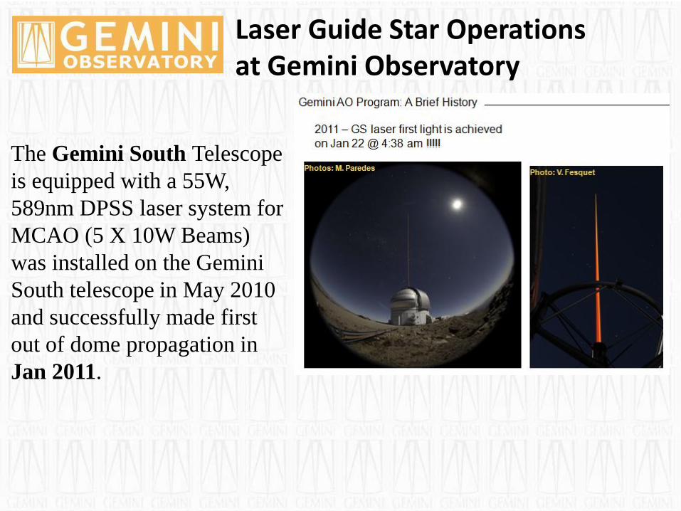
Laser Guide Star Operations at Gemini Observatory
The Gemini North Telescope
is equipped with a 14W, 589nm
DPSS laser and in conjunction
with ALTAIR has been
providing Laser Guide Star
Adaptive Optics (LGS AO)
regular science Queue
observations since February
2007.
Laser Guide Star Operations at Gemini Observatory
The Gemini South Telescope
is equipped with a 55W,
589nm DPSS laser system for
MCAO (5 X 10W Beams)
was installed on the Gemini
South telescope in May 2010
and successfully made first
out of dome propagation in
Jan 2011.
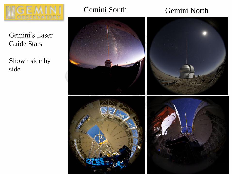
Gemini’s Laser
Guide Stars
Shown side by
side
Gemini South Gemini North
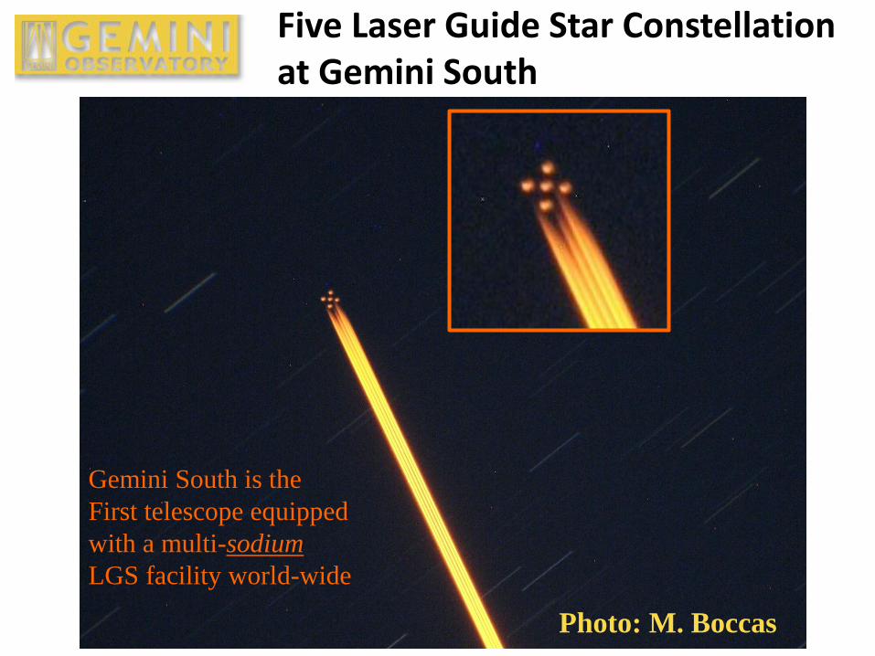
Photo: M. Boccas
Gemini South is the
First telescope equipped
with a multi-sodium
LGS facility world-wide
Five Laser Guide Star Constellation at Gemini South
Remote Laser Operations at Gemini
In this presentation, we comment on how Gemini Observatory
developed regular remote operation of the Laser Guide Star
Facility and high-power solid-state laser as routine normal
operations.
GN Laser Operation
•First out of dome propagation May 2005
•Regular science ops since February 2007
Fully remote operation of the LGSF from the Hilo base facility
HBF was initially trialed and then optimized and became the
standard operating procedure (SOP) for LGS operation in
December 2008 to present.
Show Video of LGS operations
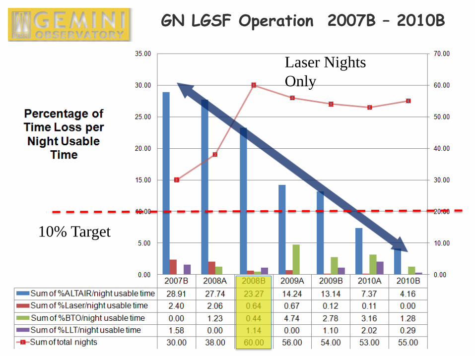
GN LGSF Operation 2007B – 2010B
10% Target
Laser Nights
Only
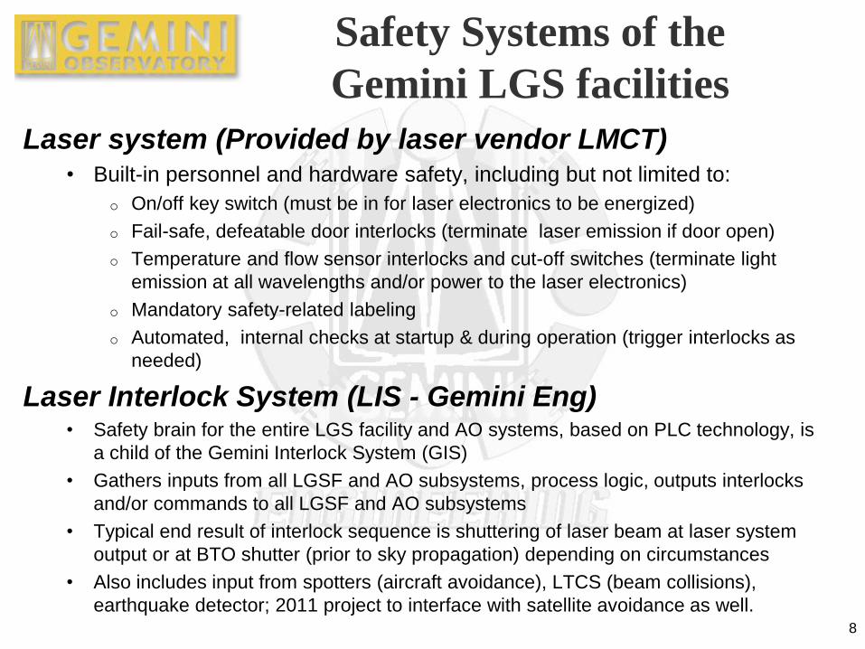
Safety Systems of the
Gemini LGS facilities
Laser system (Provided by laser vendor LMCT) • Built-in personnel and hardware safety, including but not limited to:
o On/off key switch (must be in for laser electronics to be energized)
o Fail-safe, defeatable door interlocks (terminate laser emission if door open)
o Temperature and flow sensor interlocks and cut-off switches (terminate light
emission at all wavelengths and/or power to the laser electronics)
o Mandatory safety-related labeling
o Automated, internal checks at startup & during operation (trigger interlocks as
needed)
Laser Interlock System (LIS - Gemini Eng) • Safety brain for the entire LGS facility and AO systems, based on PLC technology, is
a child of the Gemini Interlock System (GIS)
• Gathers inputs from all LGSF and AO subsystems, process logic, outputs interlocks
and/or commands to all LGSF and AO subsystems
• Typical end result of interlock sequence is shuttering of laser beam at laser system
output or at BTO shutter (prior to sky propagation) depending on circumstances
• Also includes input from spotters (aircraft avoidance), LTCS (beam collisions),
earthquake detector; 2011 project to interface with satellite avoidance as well. 8
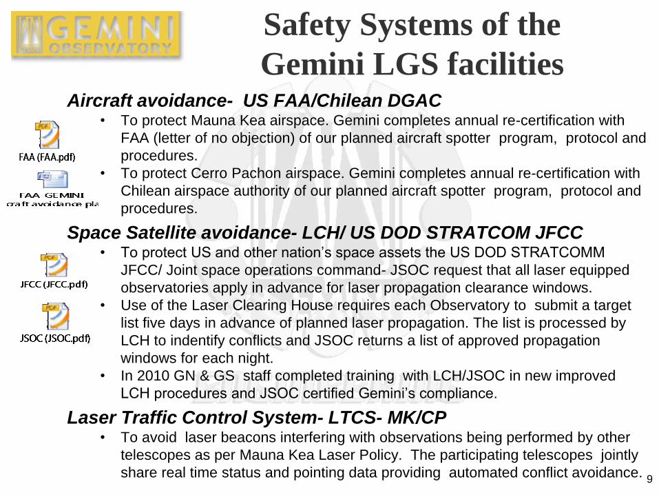
Safety Systems of the
Gemini LGS facilities Aircraft avoidance- US FAA/Chilean DGAC
• To protect Mauna Kea airspace. Gemini completes annual re-certification with
FAA (letter of no objection) of our planned aircraft spotter program, protocol and
procedures.
• To protect Cerro Pachon airspace. Gemini completes annual re-certification with
Chilean airspace authority of our planned aircraft spotter program, protocol and
procedures.
Space Satellite avoidance- LCH/ US DOD STRATCOM JFCC • To protect US and other nation’s space assets the US DOD STRATCOMM
JFCC/ Joint space operations command- JSOC request that all laser equipped
observatories apply in advance for laser propagation clearance windows.
• Use of the Laser Clearing House requires each Observatory to submit a target
list five days in advance of planned laser propagation. The list is processed by
LCH to indentify conflicts and JSOC returns a list of approved propagation
windows for each night.
• In 2010 GN & GS staff completed training with LCH/JSOC in new improved
LCH procedures and JSOC certified Gemini’s compliance.
Laser Traffic Control System- LTCS- MK/CP • To avoid laser beacons interfering with observations being performed by other
telescopes as per Mauna Kea Laser Policy. The participating telescopes jointly
share real time status and pointing data providing automated conflict avoidance. 9
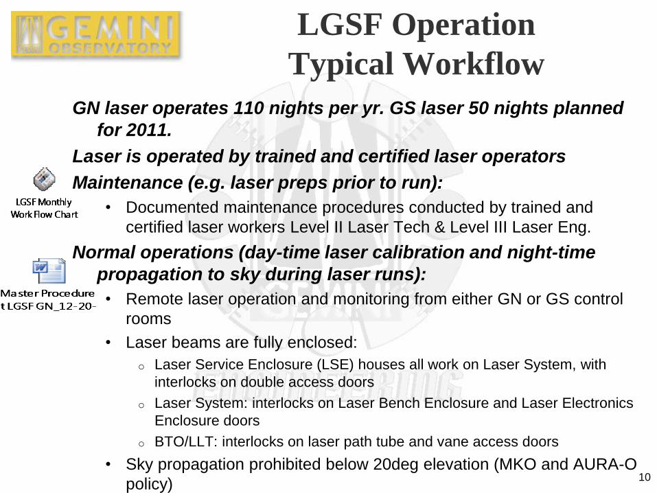
LGSF Operation
Typical Workflow
GN laser operates 110 nights per yr. GS laser 50 nights planned
for 2011.
Laser is operated by trained and certified laser operators
Maintenance (e.g. laser preps prior to run):
• Documented maintenance procedures conducted by trained and
certified laser workers Level II Laser Tech & Level III Laser Eng.
Normal operations (day-time laser calibration and night-time
propagation to sky during laser runs):
• Remote laser operation and monitoring from either GN or GS control
rooms
• Laser beams are fully enclosed:
o Laser Service Enclosure (LSE) houses all work on Laser System, with
interlocks on double access doors
o Laser System: interlocks on Laser Bench Enclosure and Laser Electronics
Enclosure doors
o BTO/LLT: interlocks on laser path tube and vane access doors
• Sky propagation prohibited below 20deg elevation (MKO and AURA-O
policy) 10
11
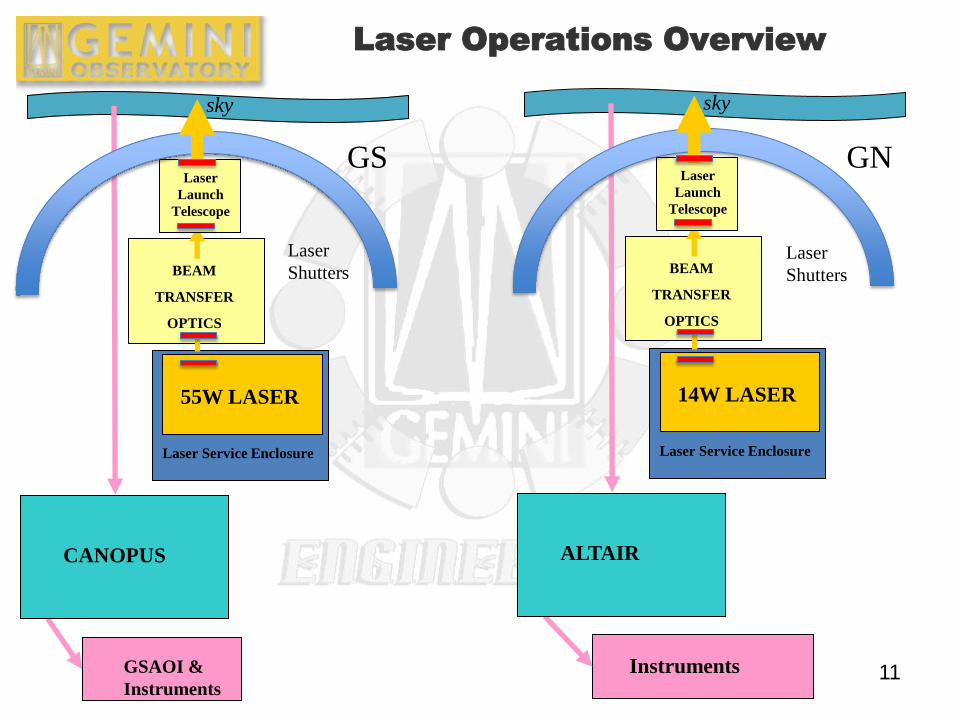
Laser Operations Overview
sky
GSAOI &
Instruments
Laser Service Enclosure
55W LASER
CANOPUS
BEAM
TRANSFER
OPTICS
Laser
Launch
Telescope
sky
Instruments
Laser Service Enclosure
14W LASER
ALTAIR
BEAM
TRANSFER
OPTICS
Laser
Launch
Telescope
Laser
Shutters Laser
Shutters
GS GN
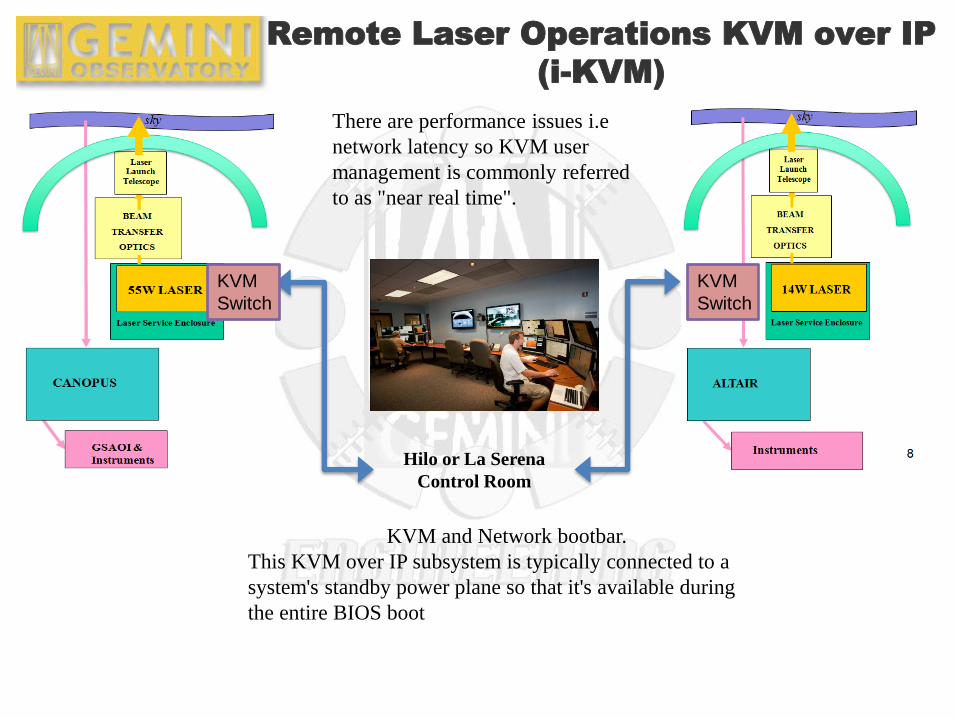
Remote Laser Operations KVM over IP
(i-KVM)
Hilo or La Serena
Control Room
There are performance issues i.e
network latency so KVM user
management is commonly referred
to as "near real time".
KVM
Switch
KVM
Switch
KVM and Network bootbar.
This KVM over IP subsystem is typically connected to a
system's standby power plane so that it's available during
the entire BIOS boot
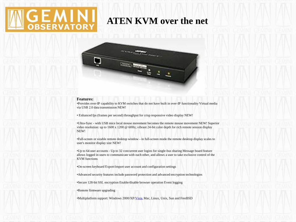
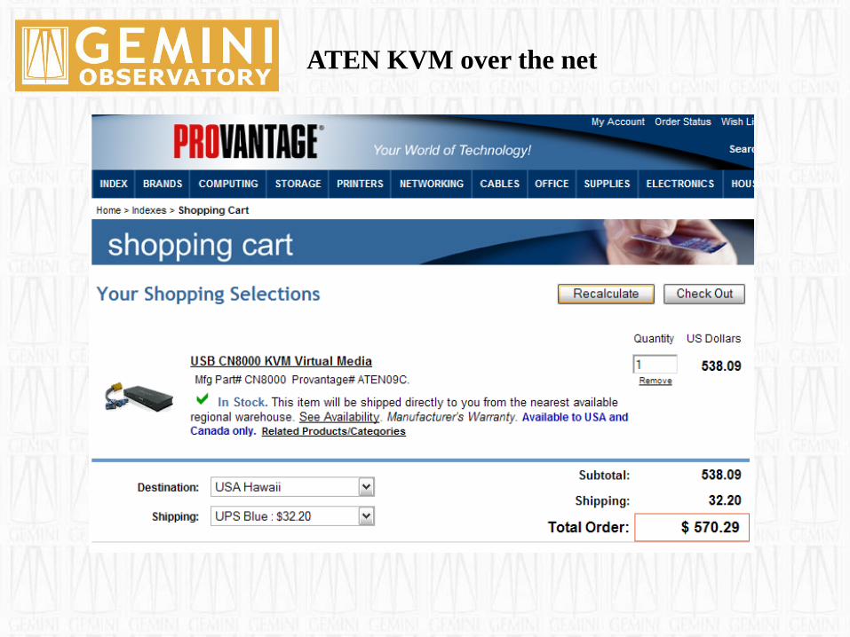
ATEN KVM over the net
Features: •Provides over-IP capability to KVM switches that do not have built in over-IP functionality Virtual media
via USB 2.0 data transmission NEW!
• Enhanced fps (frames per second) throughput for crisp responsive video display NEW!
•Ultra-Sync - with USB mice local mouse movement becomes the remote mouse movement NEW! Superior
video resolution: up to 1600 x 1200 @ 60Hz; vibrant 24-bit color depth for rich remote session display
NEW!
•Full-screen or sizable remote desktop window - in full-screen mode the remote desktop display scales to
user's monitor display size NEW!
•Up to 64 user accounts - Up to 32 concurrent user logins for single-bus sharing Message board feature
allows logged in users to communicate with each other, and allows a user to take exclusive control of the
KVM functions
•On-screen keyboard Export/import user account and configuration settings
•Advanced security features include password protection and advanced encryption technologies
•Secure 128-bit SSL encryption Enable/disable browser operation Event logging
•Remote firmware upgrading
•Multiplatform support: Windows 2000/XP/Vista, Mac, Linux, Unix, Sun and FreeBSD
ATEN KVM over the net
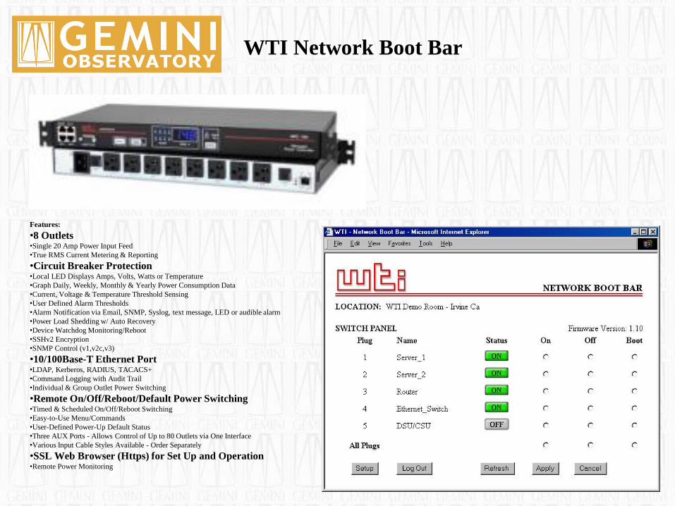
WTI Network Boot Bar
Features:
•8 Outlets •Single 20 Amp Power Input Feed
•True RMS Current Metering & Reporting
•Circuit Breaker Protection •Local LED Displays Amps, Volts, Watts or Temperature
•Graph Daily, Weekly, Monthly & Yearly Power Consumption Data
•Current, Voltage & Temperature Threshold Sensing
•User Defined Alarm Thresholds
•Alarm Notification via Email, SNMP, Syslog, text message, LED or audible alarm
•Power Load Shedding w/ Auto Recovery
•Device Watchdog Monitoring/Reboot
•SSHv2 Encryption
•SNMP Control (v1,v2c,v3)
•10/100Base-T Ethernet Port •LDAP, Kerberos, RADIUS, TACACS+
•Command Logging with Audit Trail
•Individual & Group Outlet Power Switching
•Remote On/Off/Reboot/Default Power Switching •Timed & Scheduled On/Off/Reboot Switching
•Easy-to-Use Menu/Commands
•User-Defined Power-Up Default Status
•Three AUX Ports - Allows Control of Up to 80 Outlets via One Interface
•Various Input Cable Styles Available - Order Separately
•SSL Web Browser (Https) for Set Up and Operation •Remote Power Monitoring

WTI Network Boot Bar
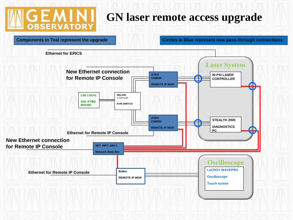
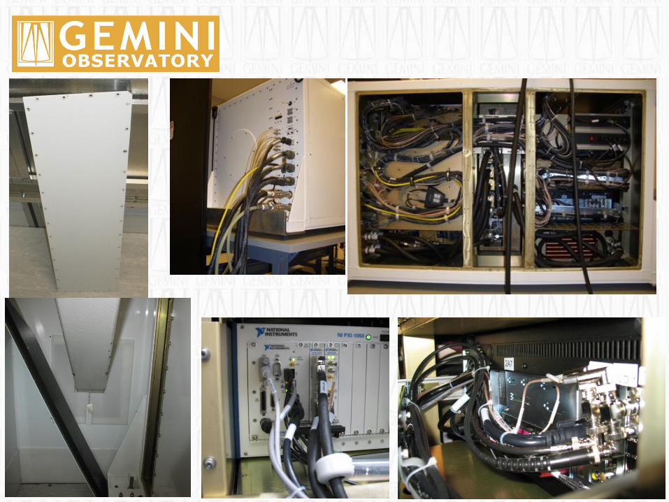
Laser System
GN laser remote access upgrade
Ethernet for EPICS
LSE LOCAL
GUI, KYBD,
MOUSE
BELKIN
F1DF102P
KVM SWITCH
New Ethernet connection
for Remote IP Console
Ethernet for Remote IP Console
Ethernet for Remote IP Console
ATEN
CN8000
REMOTE IP MGR
Belkin
REMOTE IP MGR
WTI MPC-18H-1
Network Boot Bar
STEALTH 2000
DIAGNOSTICS
PC
NI PXI LASER
CONTROLLER
Components in Teal represent the upgrade
Oscilloscope LeCROY WAVEPRO
Oscilloscope
Touch screen
Circles in Blue represent new pass-through connections
ATEN
CN8000
REMOTE IP MGR
New Ethernet connection
for Remote IP Console
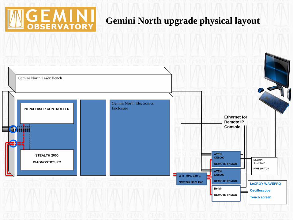
Gemini North upgrade physical layout
Gemini North Electronics
Enclosure
STEALTH 2000
DIAGNOSTICS PC
WTI MPC-18H-1
Network Boot Bar
LeCROY WAVEPRO
Oscilloscope
Touch screen
BELKIN
F1DF102P
KVM SWITCH
Ethernet for
Remote IP
Console
ATEN
CN8000
REMOTE IP MGR
ATEN
CN8000
REMOTE IP MGR
NI PXI LASER CONTROLLER
Gemini North Laser Bench
Belkin
REMOTE IP MGR
Okay, that’s how to set up
for remote operation
But,……
1) Is the laser system
reliable enough to be
operated remotely ?
2) Are we ready
to operate it ?
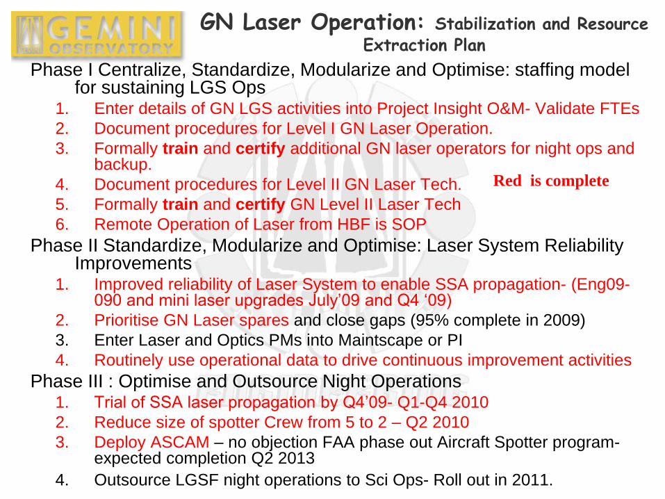
GN Laser Operation: Stabilization and Resource Extraction Plan
Phase I Centralize, Standardize, Modularize and Optimise: staffing model for sustaining LGS Ops
1. Enter details of GN LGS activities into Project Insight O&M- Validate FTEs
2. Document procedures for Level I GN Laser Operation.
3. Formally train and certify additional GN laser operators for night ops and backup.
4. Document procedures for Level II GN Laser Tech.
5. Formally train and certify GN Level II Laser Tech
6. Remote Operation of Laser from HBF is SOP
Phase II Standardize, Modularize and Optimise: Laser System Reliability Improvements
1. Improved reliability of Laser System to enable SSA propagation- (Eng09-090 and mini laser upgrades July’09 and Q4 ‘09)
2. Prioritise GN Laser spares and close gaps (95% complete in 2009)
3. Enter Laser and Optics PMs into Maintscape or PI
4. Routinely use operational data to drive continuous improvement activities
Phase III : Optimise and Outsource Night Operations 1. Trial of SSA laser propagation by Q4’09- Q1-Q4 2010
2. Reduce size of spotter Crew from 5 to 2 – Q2 2010
3. Deploy ASCAM – no objection FAA phase out Aircraft Spotter program- expected completion Q2 2013
4. Outsource LGSF night operations to Sci Ops- Roll out in 2011.
Red is complete
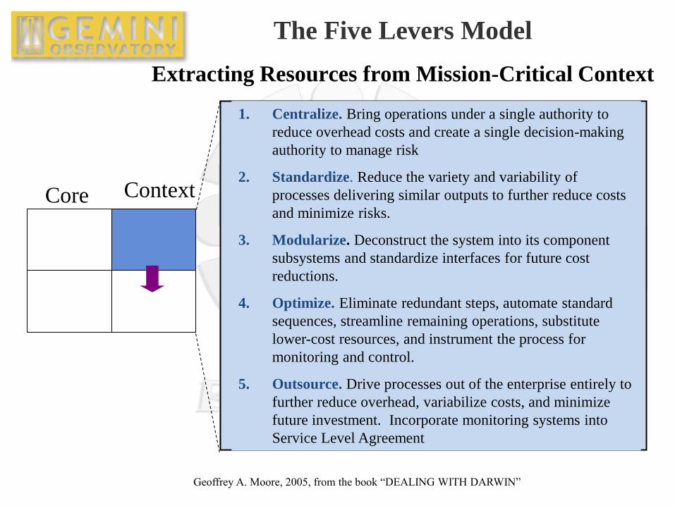
Core Context
The Five Levers Model
Extracting Resources from Mission-Critical Context
1. Centralize. Bring operations under a single authority to
reduce overhead costs and create a single decision-making
authority to manage risk
2. Standardize. Reduce the variety and variability of
processes delivering similar outputs to further reduce costs
and minimize risks.
3. Modularize. Deconstruct the system into its component
subsystems and standardize interfaces for future cost
reductions.
4. Optimize. Eliminate redundant steps, automate standard
sequences, streamline remaining operations, substitute
lower-cost resources, and instrument the process for
monitoring and control.
5. Outsource. Drive processes out of the enterprise entirely to
further reduce overhead, variabilize costs, and minimize
future investment. Incorporate monitoring systems into
Service Level Agreement
Geoffrey A. Moore, 2005, from the book “DEALING WITH DARWIN”
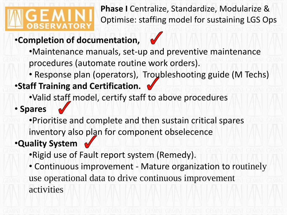
Phase I Centralize, Standardize, Modularize & Optimise: staffing model for sustaining LGS Ops
•Completion of documentation, •Maintenance manuals, set-up and preventive maintenance procedures (automate routine work orders). • Response plan (operators), Troubleshooting guide (M Techs)
•Staff Training and Certification. •Valid staff model, certify staff to above procedures
• Spares •Prioritise and complete and then sustain critical spares inventory also plan for component obselecence
•Quality System •Rigid use of Fault report system (Remedy). • Continuous improvement - Mature organization to routinely
use operational data to drive continuous improvement
activities
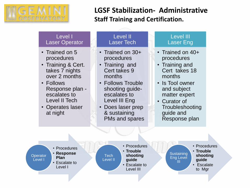
LGSF Stabilization- Administrative Staff Training and Certification.
Level I Laser Operator
• Trained on 5 procedures
• Training & Cert. takes 7 nights over 2 months
• Follows Response plan -escalates to Level II Tech
• Operates laser at night
Level II Laser Tech
• Trained on 30+ procedures
• Training and Cert takes 9 months
• Follows Trouble shooting guide- escalates to Level III Eng
• Does laser prep & sustaining PMs and spares
Level III Laser Eng
• Trained on 40+ procedures
• Training and Cert takes 18 months
• Is Tool owner and subject matter expert
• Curator of Troubleshooting guide and Response plan
• Procedures
• Response Plan
• Escalate to Level I
Operator Level I
• Procedures
• Trouble shooting guide
• Escalate to Level III
Tech Level II
• Procedures
• Trouble shooting guide
• Escalate to Mgr
Sustaining Eng Level
III
Phase II Standardize, Modularize & Optimise: Laser System Reliability Improvements
From an engineering perspective remote operation demands
stable, well characterized and base-lined equipment sets.
Stabilisation
In the effort to produce consistent, stable and controlled laser
parameters (power, wavelength and beam quality) we completed a
failure mode effect analysis (FMEA) of the laser system and sub
systems that initiated a campaign of prioritised hardware upgrades
and procedural improvements to the routine maintenance
operations.
We also did a separate FMEA on remote operation of the laser
and also continuous 24hr operation of the laser.
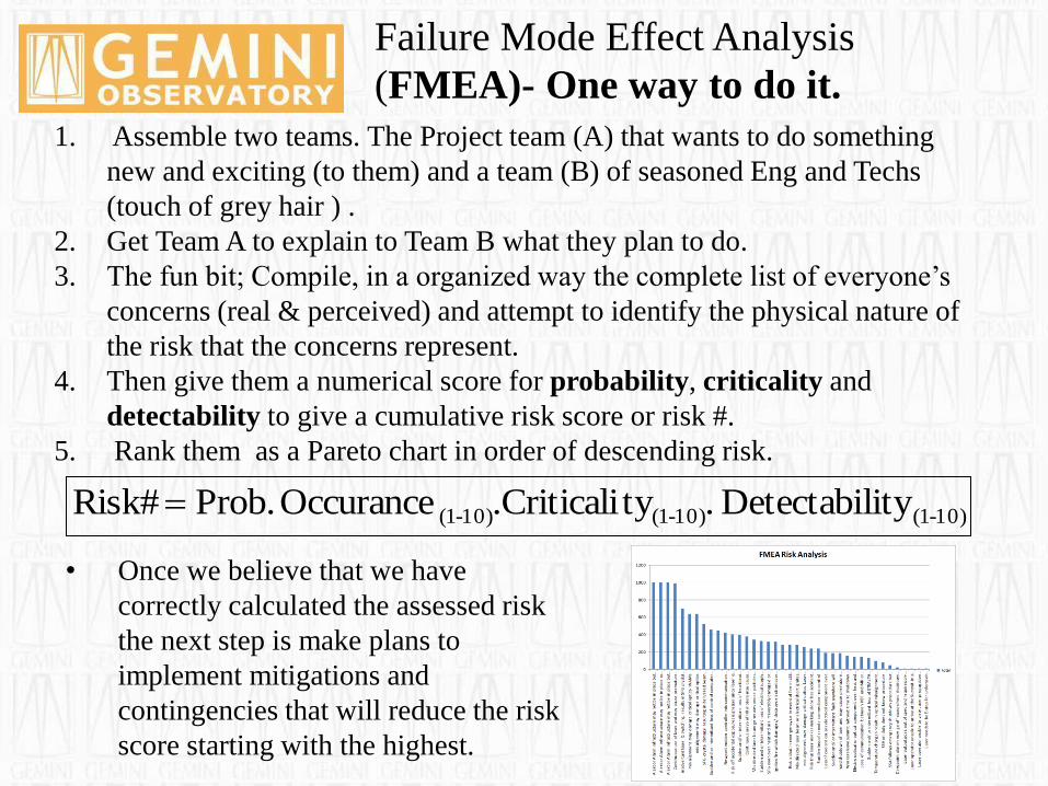
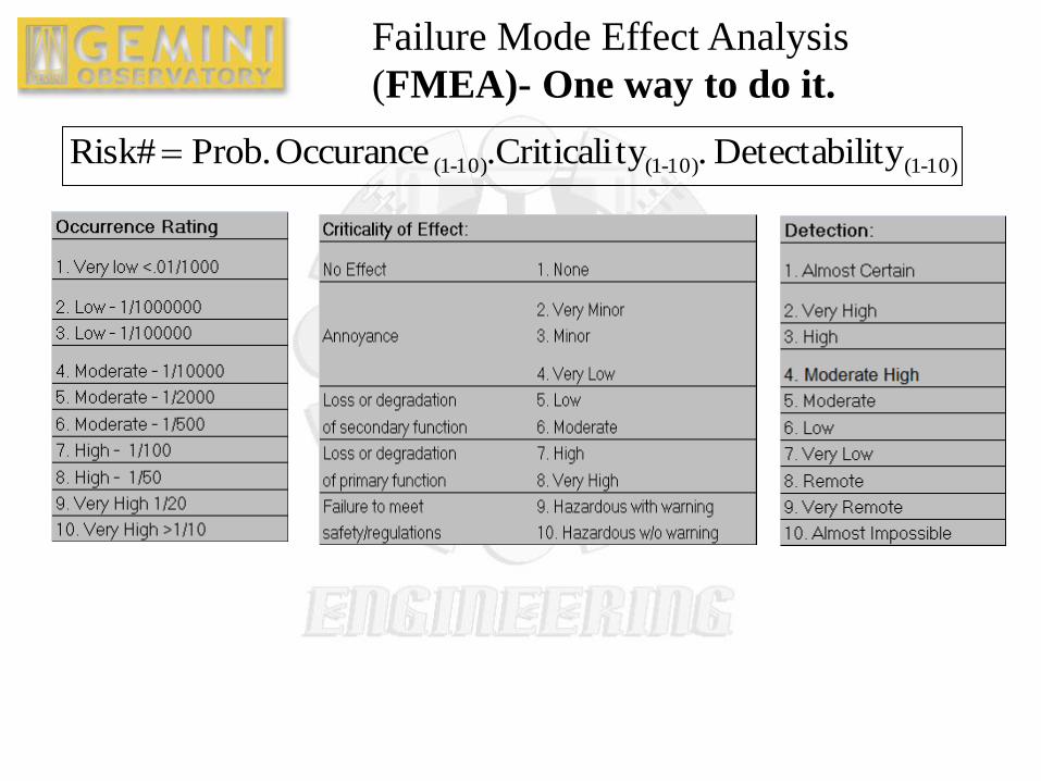
Failure Mode Effect Analysis
(FMEA)- One way to do it. 1. Assemble two teams. The Project team (A) that wants to do something
new and exciting (to them) and a team (B) of seasoned Eng and Techs
(touch of grey hair ) .
2. Get Team A to explain to Team B what they plan to do.
3. The fun bit; Compile, in a organized way the complete list of everyone’s
concerns (real & perceived) and attempt to identify the physical nature of
the risk that the concerns represent.
4. Then give them a numerical score for probability, criticality and
detectability to give a cumulative risk score or risk #.
5. Rank them as a Pareto chart in order of descending risk.
• Once we believe that we have
correctly calculated the assessed risk
the next step is make plans to
implement mitigations and
contingencies that will reduce the risk
score starting with the highest.
10)-(110)-(110)-(1 lity Detectabi.ty.CriticaliOccurance Prob. Risk#
Failure Mode Effect Analysis
(FMEA)- One way to do it.
10)-(110)-(110)-(1 lity Detectabi.ty.CriticaliOccurance Prob. Risk#
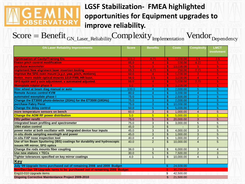
LGSF Stabilization- FMEA highlighted opportunities for Equipment upgrades to improve reliability.
GN Laser Reliability Improvements Score Benefits Costs Complexity LMCT
involvment
Optimisation of Cavity/Training Etc 101.2 4.75 1,000.00$ 1.5 2.5
Etalon pitch control modification 85.0 4 500.00$ 4.25 5
purchase wavemeter 75.0 3 13,000.00$ 5 5
Implement New alignment laser insertion tooling 65.3 4.75 250.00$ 2.75 5
Improve the SFG oven mount (x,y,z, yaw, pitch, motions) 60.0 4 5,000.00$ 3 5
Better, more stable optical mounts 1319 FM8, HR base, 56.0 3.5 3,000.00$ 4 4
SFG tip/tilt and y axis adjustment, x automated adjusted. 55.0 4 5,000.00$ 2.75 5
Waveplate rotator phase II 5.0 5 3,000.00$ 1 1
filter wheel at beam diag manual or auto 100.0 4 2,000.00$ 5 5
Remote Access control KVM 80.0 4 3,000.00$ 4 5
automated waveplate phase I 75.0 5 2,500.00$ 3 5
Change the ET3000 photo-detector (2GHz) for the ET3500 (10GHz) 75.0 3 2,000.00$ 5 5
purchase Fabry Perot 75.0 3 10,000.00$ 5 5
Change the delay control 50.0 5 5,000.00$ 2 5
more temperature sensors on bench 60.0 3 1,000.00$ 4 5
Change the AOM RF power distribution 5.0 5 5,000.00$ 1 1
FRU peltier rerofit 75.0 5 20,000.00$ 3 5
integrated beam profiling and spectrometer 75.0 3 3,000.00$ 5 5
1064 etalon control 45.0 3 -$ 3 5
power meter at both oscillator with integrated device four inputs 45.0 3 4,000.00$ 3 5
in-situ diode sampling wavelegth and power 45.0 3 1,000.00$ 3 5
in-situ FAP nose inspection tool 40.0 4 1,000.00$ 2 5Use of Ion Beam Sputtering (IBS) coatings for durability and hydroscopic
issues HR mirror, SFG optics
40.0 2 10,000.00$ 4 5
Change the rods mounts fiber coupling 36.0 3 6,000.00$ 3 4
Use new etalons + TECs 30.0 5 7,500.00$ 2 3
Tighter tolerances specified on key mirror coatings 4.0 1 10,000.00$ 4 1
KeyJuly '09 Upgrade items purchased out of remaining 2008 and 2009 Budget 24,500.00$
Nov/Dec/Jan '09 Upgrade items to be purchased out of remaining 2009 Budget 30,750.00$
Eng10-010 Upgrade items 42,500.00$
Ongoing Corrective Maintentance Project 2009-2010 21,500.00$
DependencytionImplementaeliabilityGN_Laser_R Vendor ComplexityBenefitScore
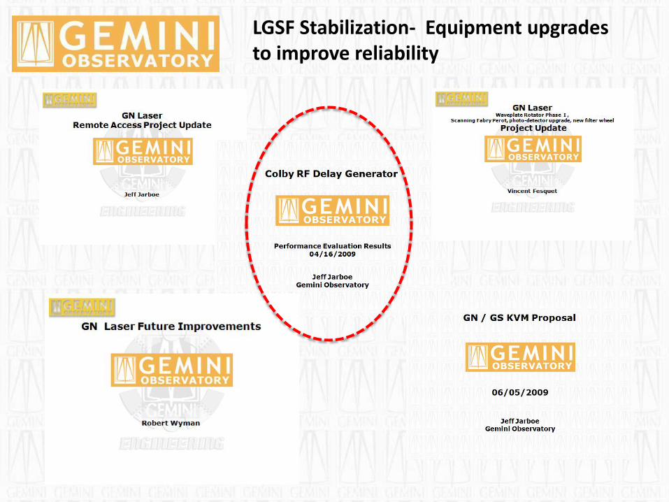
LGSF Stabilization- Equipment upgrades to improve reliability
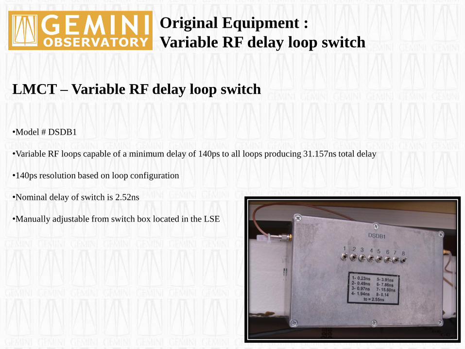
LMCT – Variable RF delay loop switch
•Model # DSDB1
•Variable RF loops capable of a minimum delay of 140ps to all loops producing 31.157ns total delay
•140ps resolution based on loop configuration
•Nominal delay of switch is 2.52ns
•Manually adjustable from switch box located in the LSE
Original Equipment :
Variable RF delay loop switch
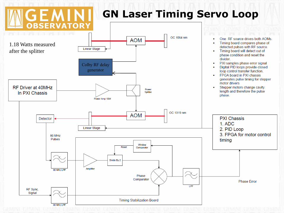
GN Laser Timing Servo Loop
Colby RF delay
generator
1.18 Watts measured
after the splitter
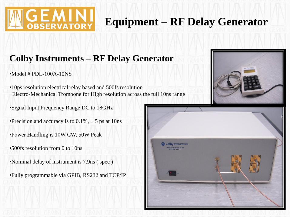
Colby Instruments – RF Delay Generator
•Model # PDL-100A-10NS
•10ps resolution electrical relay based and 500fs resolution
Electro-Mechanical Trombone for High resolution across the full 10ns range
•Signal Input Frequency Range DC to 18GHz
•Precision and accuracy is to 0.1%, ± 5 ps at 10ns
•Power Handling is 10W CW, 50W Peak
•500fs resolution from 0 to 10ns
•Nominal delay of instrument is 7.9ns ( spec )
•Fully programmable via GPIB, RS232 and TCP/IP
Equipment – RF Delay Generator
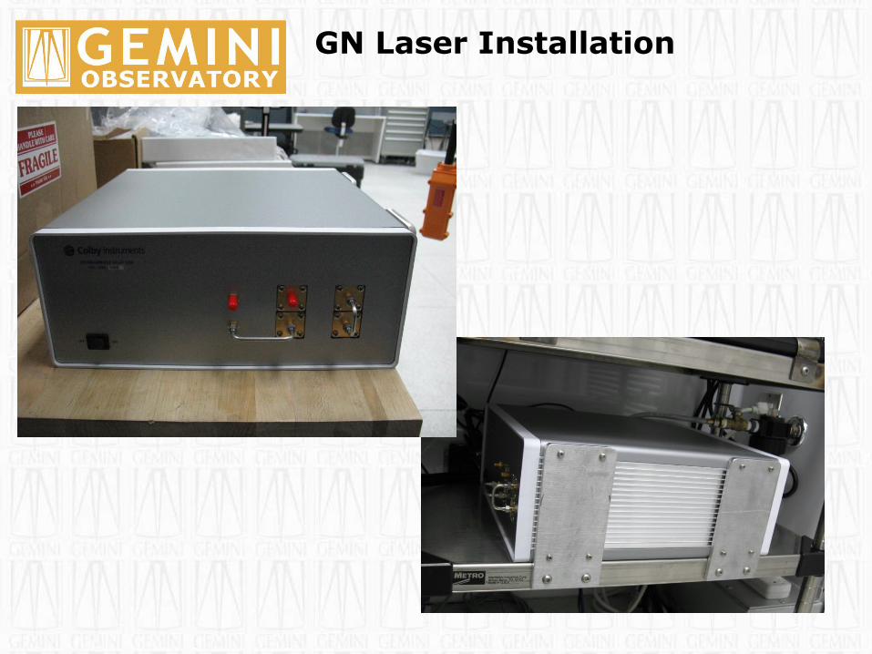
GN Laser Installation
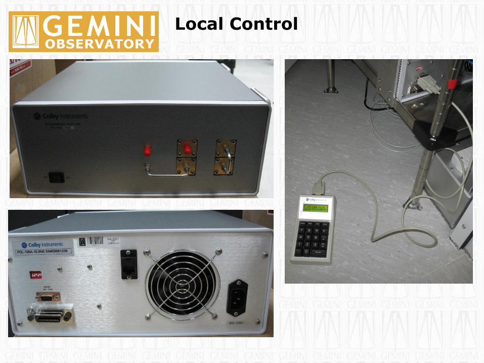
Local Control
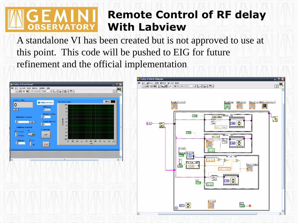
Remote Control of RF delay With Labview
A standalone VI has been created but is not approved to use at
this point. This code will be pushed to EIG for future
refinement and the official implementation
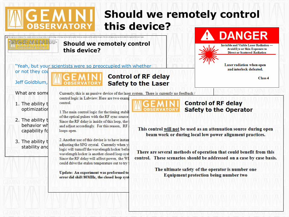
Should we remotely control this device?
Should we remotely control this device?
“Yeah, but your scientists were so preoccupied with whether or not they could, they didn't stop to think if they should”
Jeff Goldblum, Jurassic Park 1993
What are some of the benefits of remote control.
1. The ability to have independent control of oscillator optimization while maintaining a constant phase delay.
2. The ability to propagate at low power to monitor the BTO behavior while offering almost instant high power capability for LGS operations.
3. The ability to develop a closed loop system to increase stability and reliability for SSA operation.

LGSF Stabilization- Equipment upgrades to improve reliability
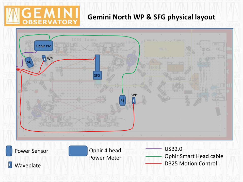
Gemini North WP & SFG physical layout
Power Sensor Waveplate
USB2.0 Ophir Smart Head cable DB25 Motion Control
PS
PS
WP
WP
SFG
Ophir PM
Ophir 4 head Power Meter

Gemini North Upgrade ”Remote Operations” Current Hardware Procurement
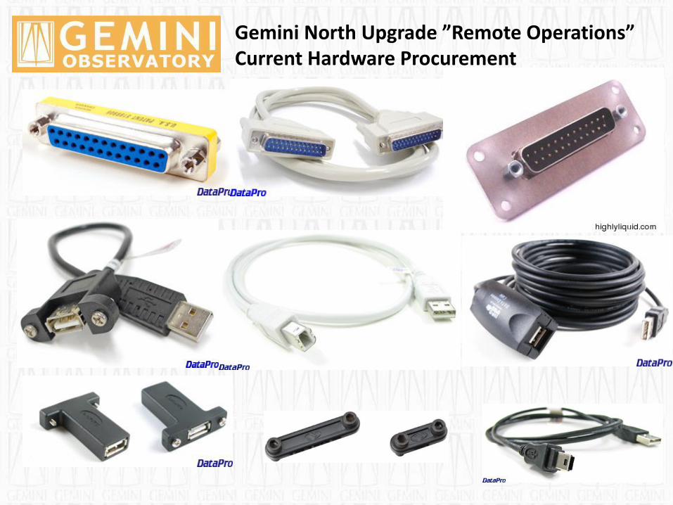
Gemini North Upgrade ”Remote Operations” Current Hardware Procurement

Gemini North Upgrade ”Remote Operations” Current Hardware Procurement
Ophir - Smart Head to USB Interface and Four Channel Pulsar 1-4 Ophir basic smart head to USB interface for single channel and high speed Pulsar series for 1-4 channels turn your PC or laptop into a full fledged Ophir multi-channel laser power/energy meter. Just install the software, plug the head into the interface box and the USB cable from the box to the PC USB port. Using the USB Interface, you can connect several heads to the PC by using one box for each head and if necessary, a USB hub. With the Pulsar-4 ,Pulsar-2 and Pulsar-1 series, you can connect up to 4 heads to each box, monitor each pulse at up to 20KHz and utilize external trigger. The connection from each box to the PC is via one USB cable.
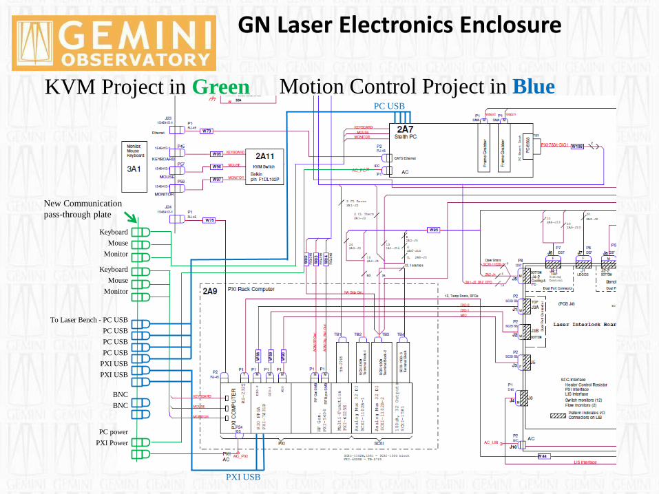
GN Laser Electronics Enclosure
Keyboard
Mouse
Monitor
Keyboard
Mouse
Monitor
To Laser Bench - PC USB
PC USB
PC USB
PC USB
PXI USB
PXI USB
BNC
BNC
PC power
PXI Power
KVM Project in Green Motion Control Project in Blue PC USB
PXI USB
New Communication
pass-through plate

GN Laser Enclosure “Laser Bench”
New Communication
pass-through plate
Motion Control Power Meters
Electro
nics C
abin
et – U
SB
US
B
BN
C
BN
C
12
Volt p
ow
er
pass-th
rou
gh
Gro
mm
et
10
64
WP
R - D
B2
5
13
19
WP
R - D
B2
5
SF
G L
inear A
ctuato
r – D
B2
5
1064 Waveplate Rotator
1319 Waveplate Rotator
SFG Linear Actuator
Ophir Power
Meter
1064 PS
1319 PS
Gemini North Laser Bench
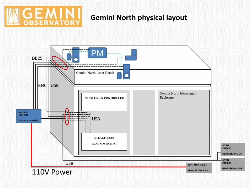
Gemini North physical layout
Gemini North Electronics
Enclosure
WTI MPC-18H-1
Network Boot Bar
STEALTH 2000
DIAGNOSTICS PC
NI PXI LASER CONTROLLER
Newport
ESP-301
Motion controller
ATEN
CN8000
REMOTE IP MGR
ATEN
CN8000
REMOTE IP MGR
USB
DB25 PM
USB
110V Power USB
BNC
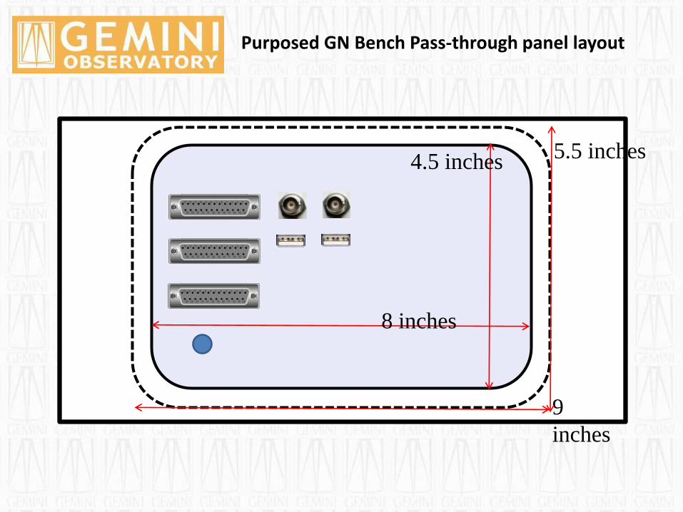
Purposed GN Bench Pass-through panel layout
8 inches
4.5 inches
9
inches
5.5 inches
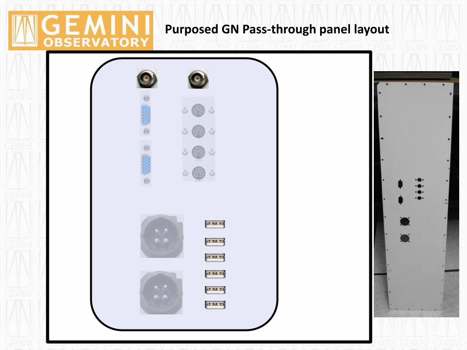
Purposed GN Pass-through panel layout
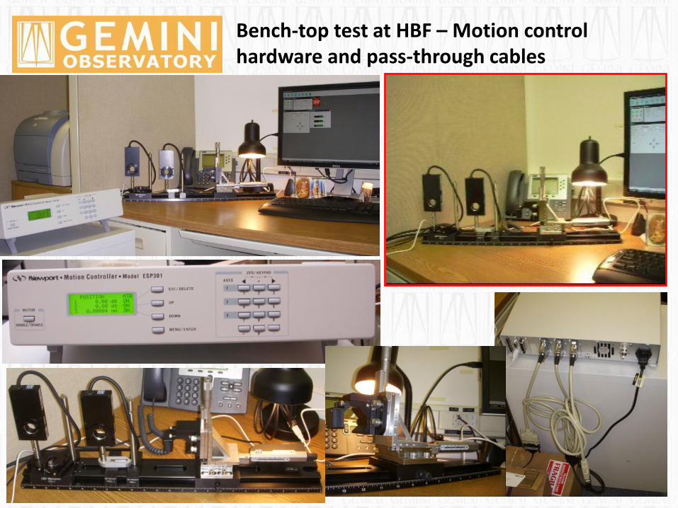
Bench-top test at HBF – Motion control hardware and pass-through cables

Bench-top test at HBF Ophir power meter
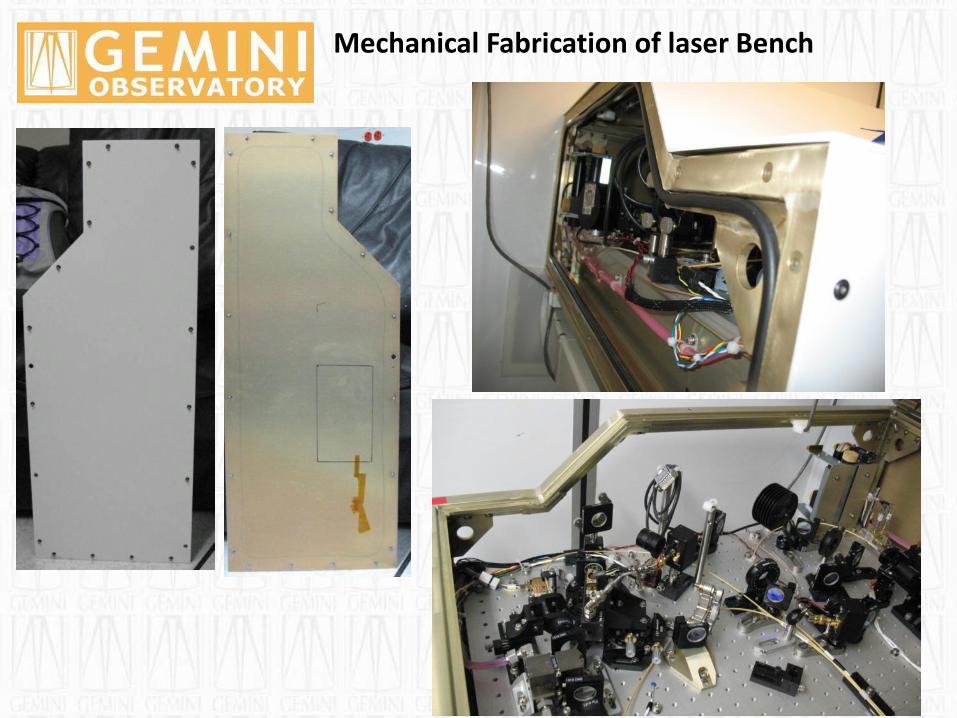
Mechanical Fabrication of laser Bench

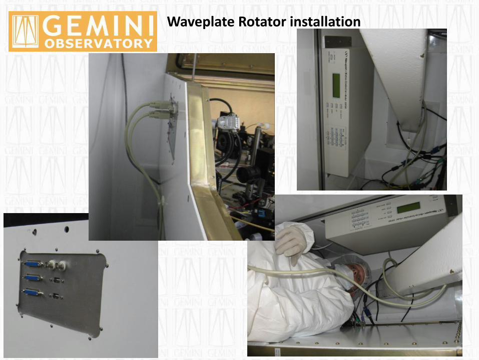
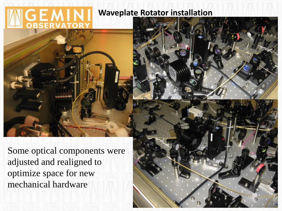
Waveplate Rotator installation
Waveplate Rotator installation
Waveplate Rotator installation
Some optical components were
adjusted and realigned to
optimize space for new
mechanical hardware
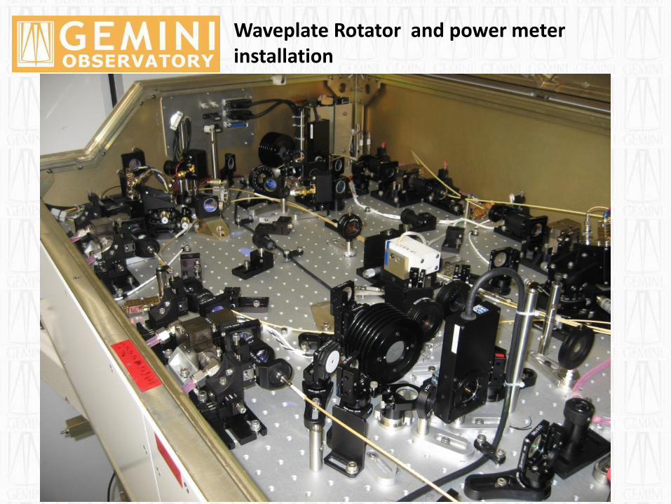
Waveplate Rotator and power meter installation
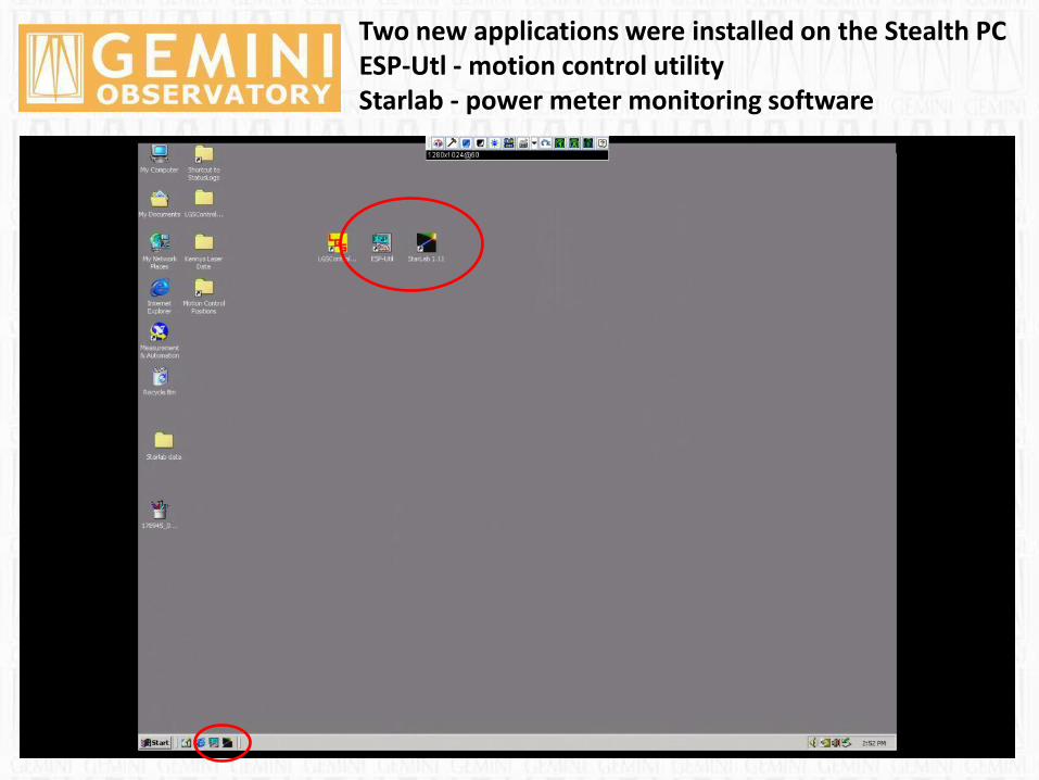
Two new applications were installed on the Stealth PC ESP-Utl - motion control utility Starlab - power meter monitoring software
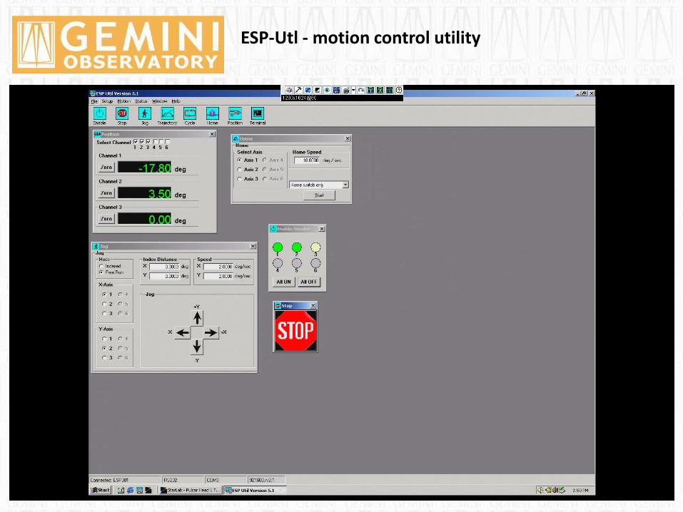
ESP-Utl - motion control utility
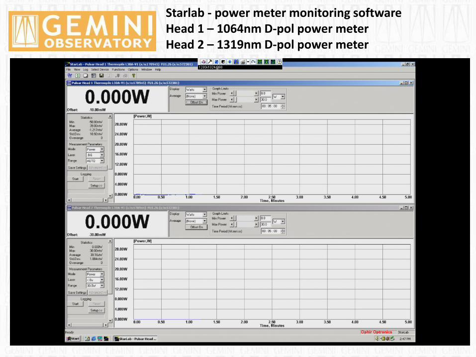
Starlab - power meter monitoring software Head 1 – 1064nm D-pol power meter Head 2 – 1319nm D-pol power meter
Remote Laser Operations at Gemini North and Gemini South
Finally, we provide an overview of normal operation procedures
during LGS runs and present a snapshot of data accumulated over
several years that describes the overall LGS AO observing
efficiency at the Gemini North telescope.
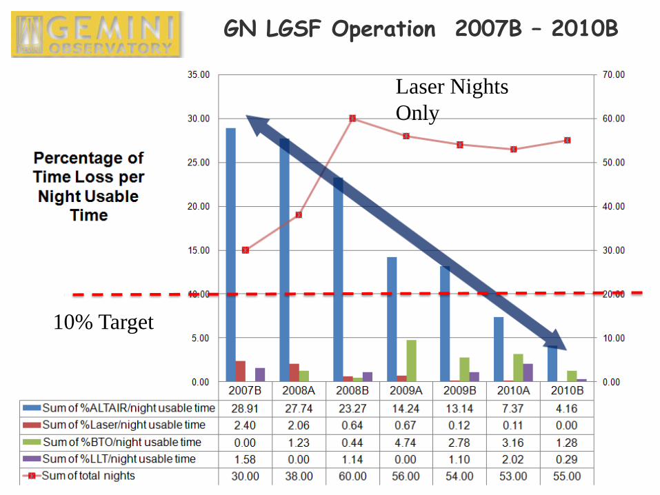
GN LGSF Operation 2007B – 2010B
10% Target
Laser Nights
Only
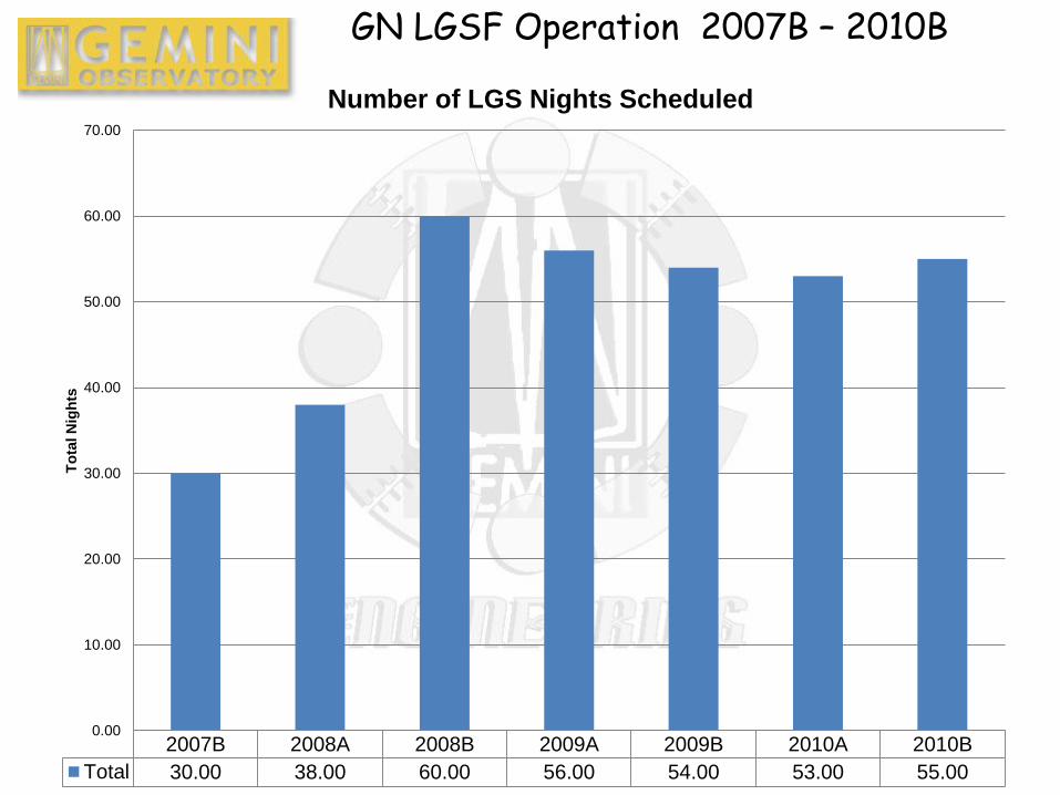
2007B 2008A 2008B 2009A 2009B 2010A 2010B
Total 30.00 38.00 60.00 56.00 54.00 53.00 55.00
0.00
10.00
20.00
30.00
40.00
50.00
60.00
70.00
To
tal N
igh
ts
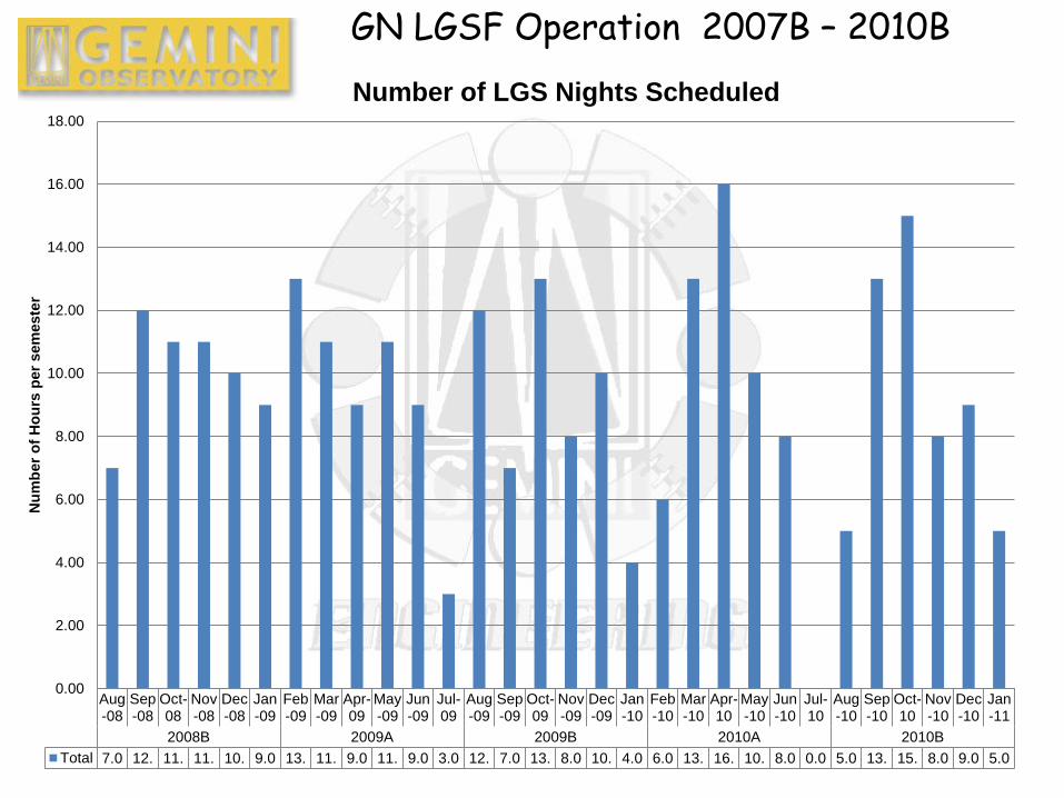
Number of LGS Nights Scheduled
GN LGSF Operation 2007B – 2010B
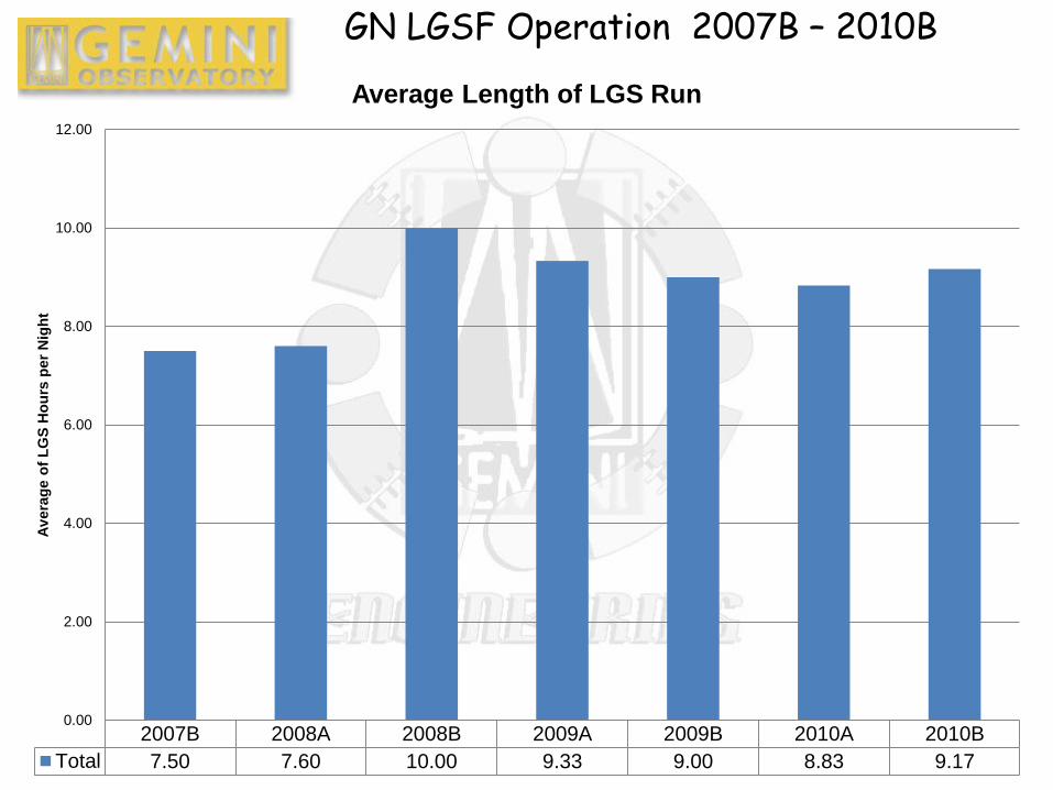
2007B 2008A 2008B 2009A 2009B 2010A 2010B
Total 7.50 7.60 10.00 9.33 9.00 8.83 9.17
0.00
2.00
4.00
6.00
8.00
10.00
12.00
Av
era
ge o
f L
GS
Ho
urs
per
Nig
ht
Average Length of LGS Run
GN LGSF Operation 2007B – 2010B
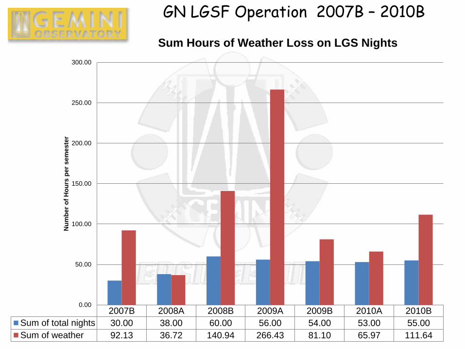
2007B 2008A 2008B 2009A 2009B 2010A 2010B
Sum of total nights 30.00 38.00 60.00 56.00 54.00 53.00 55.00
Sum of weather 92.13 36.72 140.94 266.43 81.10 65.97 111.64
0.00
50.00
100.00
150.00
200.00
250.00
300.00N
um
ber
of
Ho
urs
per
sem
este
r
Sum Hours of Weather Loss on LGS Nights
GN LGSF Operation 2007B – 2010B
Aug-08
Sep-08
Oct-08
Nov-08
Dec-08
Jan-09
Feb-09
Mar-09
Apr-09
May-09
Jun-09
Jul-09
Aug-09
Sep-09
Oct-09
Nov-09
Dec-09
Jan-10
Feb-10
Mar-10
Apr-10
May-10
Jun-10
Jul-10
Aug-10
Sep-10
Oct-10
Nov-10
Dec-10
Jan-11
2008B 2009A 2009B 2010A 2010B
Total 7.0 12. 11. 11. 10. 9.0 13. 11. 9.0 11. 9.0 3.0 12. 7.0 13. 8.0 10. 4.0 6.0 13. 16. 10. 8.0 0.0 5.0 13. 15. 8.0 9.0 5.0
0.00
2.00
4.00
6.00
8.00
10.00
12.00
14.00
16.00
18.00
Nu
mb
er
of
Ho
urs
per
sem
este
r
Number of LGS Nights Scheduled
GN LGSF Operation 2007B – 2010B
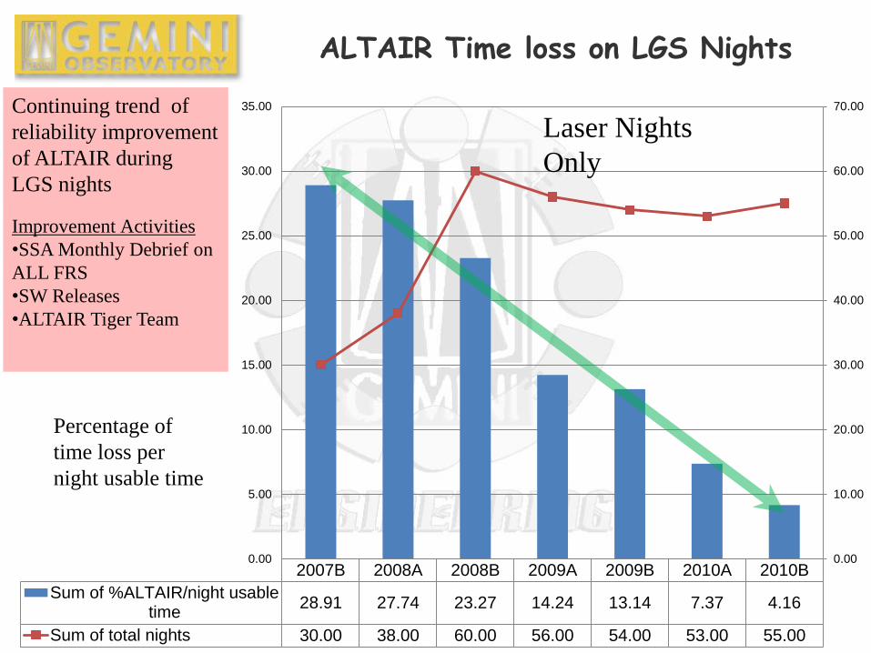
2007B 2008A 2008B 2009A 2009B 2010A 2010B
Sum of %ALTAIR/night usabletime
28.91 27.74 23.27 14.24 13.14 7.37 4.16
Sum of total nights 30.00 38.00 60.00 56.00 54.00 53.00 55.00
0.00
10.00
20.00
30.00
40.00
50.00
60.00
70.00
0.00
5.00
10.00
15.00
20.00
25.00
30.00
35.00
ALTAIR Time loss on LGS Nights
Continuing trend of
reliability improvement
of ALTAIR during
LGS nights
Improvement Activities
•SSA Monthly Debrief on
ALL FRS
•SW Releases
•ALTAIR Tiger Team
Percentage of
time loss per
night usable time
Laser Nights
Only
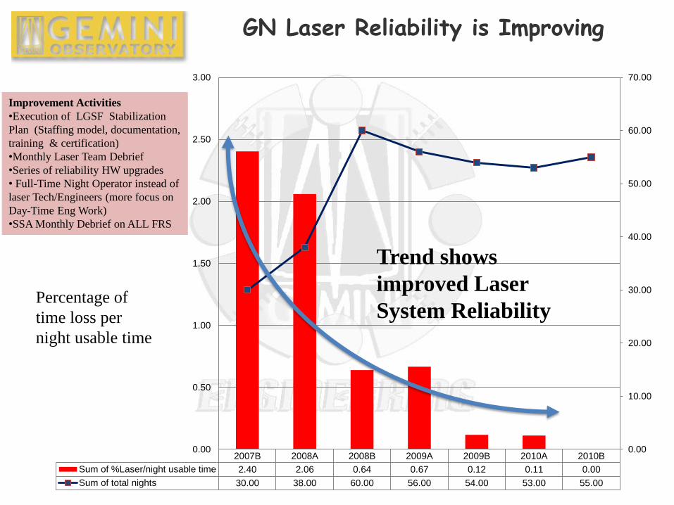
2007B 2008A 2008B 2009A 2009B 2010A 2010B
Sum of %Laser/night usable time 2.40 2.06 0.64 0.67 0.12 0.11 0.00
Sum of total nights 30.00 38.00 60.00 56.00 54.00 53.00 55.00
0.00
10.00
20.00
30.00
40.00
50.00
60.00
70.00
0.00
0.50
1.00
1.50
2.00
2.50
3.00
GN Laser Reliability is Improving
Improvement Activities
•Execution of LGSF Stabilization
Plan (Staffing model, documentation,
training & certification)
•Monthly Laser Team Debrief
•Series of reliability HW upgrades
• Full-Time Night Operator instead of
laser Tech/Engineers (more focus on
Day-Time Eng Work)
•SSA Monthly Debrief on ALL FRS
Trend shows
improved Laser
System Reliability
Percentage of
time loss per
night usable time
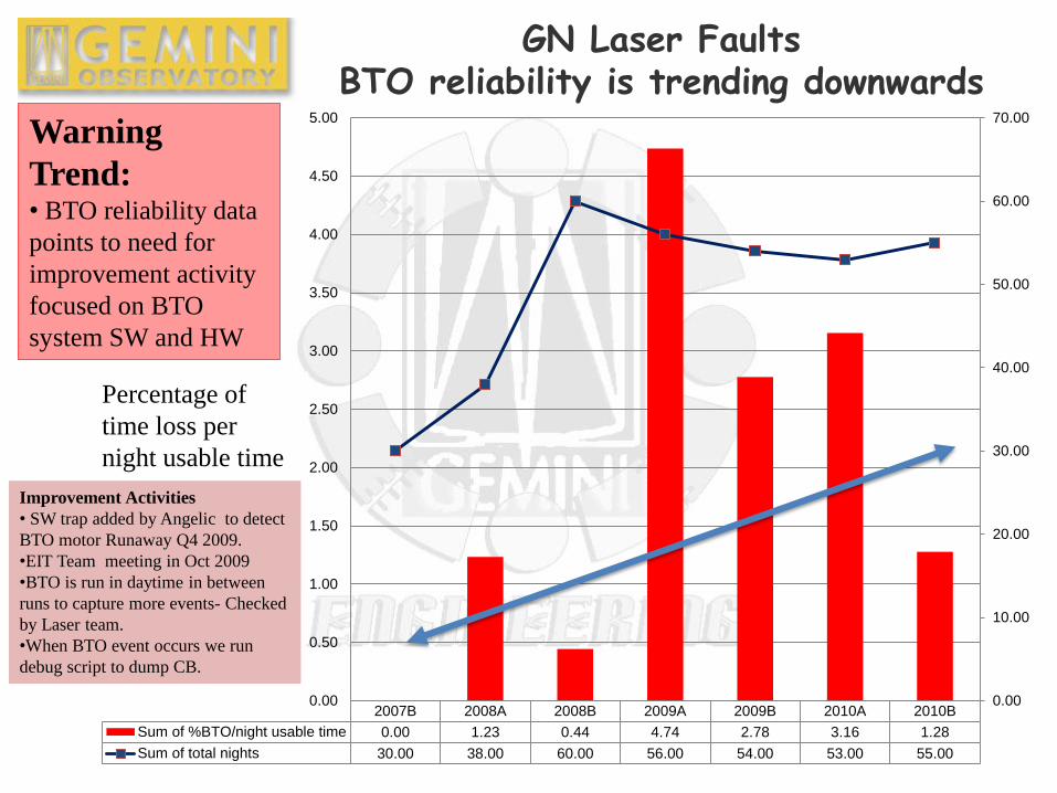
GN Laser Faults BTO reliability is trending downwards
Warning
Trend: • BTO reliability data
points to need for
improvement activity
focused on BTO
system SW and HW
Percentage of
time loss per
night usable time
Improvement Activities
• SW trap added by Angelic to detect
BTO motor Runaway Q4 2009.
•EIT Team meeting in Oct 2009
•BTO is run in daytime in between
runs to capture more events- Checked
by Laser team.
•When BTO event occurs we run
debug script to dump CB.
2007B 2008A 2008B 2009A 2009B 2010A 2010B
Sum of %BTO/night usable time 0.00 1.23 0.44 4.74 2.78 3.16 1.28
Sum of total nights 30.00 38.00 60.00 56.00 54.00 53.00 55.00
0.00
10.00
20.00
30.00
40.00
50.00
60.00
70.00
0.00
0.50
1.00
1.50
2.00
2.50
3.00
3.50
4.00
4.50
5.00
Summary and conclusion
Fully remote operation of the LGS from the Hilo base facility
HBF was initially trialed and then optimized and became the
standard operating procedure (SOP) for LGS operation in
December 2008 to present. So far remote laser operation has
worked very well.
In near future (2011) Gemini plans to offload night operation of
laser and propagation to Telescope Operator.
Presently, we are working on deploying and stabilising the GS
laser system and plan to use same model as GN to achieve
remote operation laser.
Acknowledgements Laser Ops are “handled” by a large group of staff.
Adrienne Notely, Korey Halsch, Rob Wyman, Jeff Donahue, Jeff
Jarboe, Kevin White, Maxime Boccas, Vincent Fesquet, Stan
Karewicz, John White, Jose Soto, Ramon Galvez, Mike Sheehan,
Rolando Rogers, Inger Jorgensen, Chad Trujillo, Chas Cavedoni,
Gelys Trancho, Angelic Ebbers, Matt Rippa, Tom Cummings,
Steve Hardash, Julian Christo, Clayton Ah Hee, Mike Beecher,
Gerry Brower, Simon Chan, Andy Flach, Andrew Serio, Tony
Matulonis, Jesse Ball, Matt Dillman, Dolores Coulson, Atsuko
Nitta, Rachel Mason, Bernie Walp, Brian Walls, Callie McNew,
Chris Yamasaki, Christian Schaeber, Claire Tanaka, Guastavo
Arriagada, Joel Garber, John Randrup, Jon Archambeau, Kathy
Roth, Layne Novak, Mathieu Bec, Paul Collins, Ricardo
Schiavon, Rosemary Pike, Thomas, Schneider, Tom Geballe,
Tony Oliver, Tony Baugh, ……………………….
Apologies if any name is overlooked..

Any Questions ?