remote radar based on chaos generation and radio over fiber
DESCRIPTION
Remote radar based on chaos generation and radio over fiberTRANSCRIPT

Remote Radar Based on Chaos Generationand Radio Over FiberVolume 6, Number 5, October 2014
Mingjiang Zhang, Member, IEEEYongning JiYongning ZhangYuan WuHang XuWeipeng Xu
DOI: 10.1109/JPHOT.2014.23526281943-0655 Ó 2014 IEEE

Remote Radar Based on Chaos Generationand Radio Over Fiber
Mingjiang Zhang,1,2 Member, IEEE, Yongning Ji,1,2 Yongning Zhang,1,2
Yuan Wu,1 Hang Xu,1 and Weipeng Xu1
1Key Lab of Advanced Transducers and Intelligent Control System, Ministry of Education andShanxi Province, Taiyuan University of Technology, Taiyuan 030024, China
2Institute of Optoelectronic Engineering, College of Physics and Optoelectronics,Taiyuan University of Technology, Taiyuan 030024, China
DOI: 10.1109/JPHOT.2014.23526281943-0655 Ó 2014 IEEE. Translations and content mining are permitted for academic research only.
Personal use is also permitted, but republication/redistribution requires IEEE permission.See http://www.ieee.org/publications_standards/publications/rights/index.html for more information.
Manuscript received July 2, 2014; revised August 8, 2014; accepted August 9, 2014. Date of cur-rent version September 8, 2014. This work was supported by the National Natural Science Foundationof China (NSFC) under Grant 61108027, Grant 61227016, Grant 61205142, and Grant 61377089;by the China Postdoctoral Science Foundation under Grant 2011M500048; by the Program forthe Top Young Academic Leaders of Higher Learning Institutions of Shanxi (TYAL) under Grant2012lfjyt08; and by the Key Laboratory of Optoelectronic Devices and Systems of the Ministry of Edu-cation and Guangdong Province under Grant GD201305. Corresponding author: M. Zhang (e-mail:[email protected]).
Abstract: An ultrawideband (UWB) radar system for remote ranging based onmicrowave-photonic chaotic signal generation and fiber-optic distribution is proposedand demonstrated experimentally. In this system, an optical-feedback semiconductorlaser with optical injection in the central office generates photonic UWB chaos as probingsignal, and two single-mode fibers transport the optical signal to the remote antennamonitoring terminal and return the corresponding echoed signal back to the centraloffice. In the remote antenna terminal, the photonic signal is transformed into microwavechaos by a fast photodetector and then launched to target by a transmitting antenna,and the echoed signal received by another antenna is converted into optical domain bymodulating a laser diode. The target ranging is achieved at the central office by correlat-ing the echoed signal with the reference signal. We experimentally realize a detectionrange of 8 m, for a free-space target, after 24-km remote distance, and achieve a rang-ing resolution of 3 cm for single target and 8 cm for double targets. In another fiber linkbranch with 15-km fiber transmission, we obtained the 2-cm ranging resolution for asingle target.
Index Terms: Chaos, remote radar, semiconductor lasers.
1. IntroductionThe Federal Communication Commission (FCC) defines ultra-wideband (UWB) as any signalthat occupies more than 500 MHz of 10 dB bandwidth or with a fractional bandwidth beyond20% [1]. UWB technology has many advantages, such as high rate, low complexity, low costand low power consumption, immunity to multipath fading, low probability of intercept, highrange resolution, etc. [2]. Therefore, UWB technology is widely used in such fields as highspeed wireless communication [3], [4], sensor networks [5], through-wall imaging radar [6], [7],high precision positioning [8], [9], and ranging radar [10], [11].
The UWB ranging radar can be roughly divided into three categories based on the detectingsignal waveform: impulse signal radar, random signal radar, and chaotic radar. Using FCC
Vol. 6, No. 5, October 2014 7902412
IEEE Photonics Journal Radar Based on Chaos and Radio Over Fiber

conforming UWB pulses, Low et al. presented an algorithm for precise determination of the dis-tance between a pair of UWB antennas [12]. The probing signal of random signal radar is anoise or modulated by a low frequency random/pseudo-random noise [13]. For example,Narayanan et al. demonstrated a UWB random noise radar and obtained a 15 cm ranging reso-lution [14]. Chaotic radar has aroused great interests, due to its advantages such as high rangeresolution, good anti-jamming ability, and “thumbtack” ambiguity function [15], [16]. Moreover,chaotic signal with more than 10 GHz bandwidth can be obtained by utilizing nonlinear laserdynamics, which will meet the demand of higher range accuracy. Lin et al. proposed a chaoticradar based on laser chaos and achieved a range resolution of 9 cm [17].
Although UWB technology has many advantages, by wireless transmission, UWB signals canonly transmit over a short distance from a few meters to tens of meters. In order to broaden theeffective coverage of UWB signals, researchers proposed and demonstrated UWB-over-fiber forUWB wireless communications [18]–[20]. To distribute UWB signals via optical fiber, it is highlydesired that the UWB signals can be directly generated in optical domain. And then, variousmethods for photonic UWB signals generation have been presented in recent years [21]–[28].
Similarly, for the UWB ranging radar, in order to obtain antenna remote control, the opticalfiber would be the perfect distribution medium compared with the RF cable. As a kind of lowloss and broad bandwidth medium, the optical fiber can transmit the photonic UWB signals overlong distance from central office to antenna unit of radar system to realizing the antenna remot-ing. In 2012, Grodensky et al. [29] proposed and demonstrated a remote ranging microwave-photonic UWB noise radar based on the amplified spontaneous emission (ASE) associated withthe optical gain of stimulated Brillouin scattering (SBS) and of erbium-doped fiber amplifiers(EDFAs). Through 10-km optical fiber distribution, and within 3-m spatial distance, the rangeresolutions of 10 cm using EDFA-ASE and of 20 cm utilizing SBS-ASE were obtained respec-tively. In our preliminary experiments, we proposed a UWB microwave-photonic chaotic radarfor remote ranging [30] and for remote water-level monitoring [31]. In 2014, Zheng et al. de-monstrated a fiber-distributed UWB noise radar, which has a space resolution with cm-levelafter 3-km fiber transmission [32]. In this paper, we demonstrate a microwave-photonic chaoticUWB radar system for remote ranging based on the chaotic signal generation and fiber-opticdistribution, which has potential for military radar, hilltop under the bad conditions, the radar sys-tems in islands, dangerous areas and harsh industrial environment. The chaotic UWB signalsare generated by using an optically injected semiconductor laser with optical feedback in thecentral office. A long distance, two-way fiber link is utilized for antenna-remoting. Within 24 kmfiber distribution and 8 m free space transmission, range resolutions of 3 cm for single-targetdetecting and 8 cm for double-target detecting are achieved in a proof-of-concept experiment.And in another fiber link branch with 15 km fiber, we obtain 2 cm space resolution along 6.5 mfree space range for single target detecting. This radar system that combines the UWB-over-fiber technology with chaos ranging not only implements the antenna remote control but gains ahigh ranging resolution as well.
2. Experimental Setup and PrincipleThe schematic diagram of the proposed microwave-photonic chaotic UWB radar system for re-mote ranging is shown in Fig. 1(a). In this system, a chaotic laser generator in central officeemits photonic UWB chaos as probing signal. The photonic UWB signal is transported to remoteantenna unit and the target corresponding echoed signal is returned back to the central officevia two-way fiber link. In the remote antenna units, the chaotic UWB signal launched to targetby transmitter, and the echoed signal is obtained by receiver. The target ranging can beachieved at the central office by correlating the echoed signal with reference signal. Moreover,the probing signal can be distributed to different fiber link branch by using a 1 : N optical switch,which could construct multi-remoting-antenna units.
Fig. 1(b) shows a proof-of-concept experimental setup of microwave-photonic chaotic UWBradar for remote ranging in a fiber link branch. In central office unit, a chaotic laser generator
Vol. 6, No. 5, October 2014 7902412
IEEE Photonics Journal Radar Based on Chaos and Radio Over Fiber

based on an optically injected semiconductor laser with optical feedback [27] is used as thesource of photonic chaotic UWB signal, which can emit broadband chaos up to about 20 GHz.A distributed feedback laser diode (DFB-LD) subject to optical feedback with a fiber ring cavityis used as a chaotic laser (the slave LD). Another DFB-LD is employed as an injection laser(the master LD) to enhance the bandwidth of the chaotic laser by injecting continuous-wave lightinto the slave LD through a 50/50 optical fiber coupler. The power and the polarization state ofinjection light can be controlled by a variable optical attenuator (VOA1) and a polarization con-troller (PC1), respectively. The feedback strength can be adjusted by an erbium-doped opticalfiber amplifier (EDFA1) and the VOA2. The PC2 is used to control the polarization state of thefeedback light into the slave LD. The output chaotic signal is split into two branches by a 20/80optical fiber coupler. By adjusting the 1 : 2 optical switch to the fiber link branch 1, then the lightin this path is transmitted over a 24 km single mode fiber (SMF1) towards the remote antennaunit as a detecting signal. This light is detected by a broadband photodetector (PD1). The con-verted electrical chaotic signal is amplified by a low noise amplifier (LNA1) and then transmittedby a directional transmitting antenna (TA) towards the target 1. When the detecting signalreaches the target 1, it will be partly reflected back. The reflected signal is collected by anotherdirectional receiving antenna (RA), amplified by a second low noise amplifier (LNA2) and con-verted into optical signal via a high-speed modulated laser diode (LD). The optical signal istransmitted back towards the central office over another 24 km single mode fiber (SMF2),through another optical switch, after amplified by EDFA2, and then detected by the PD3. Cha-otic signal in the other reference path is detected by the PD2 after a 48 km single mode fiberwhich is a delay fiber as a reference within the central office. A signal analyzer (AgilentN9020A) is used to observe the power spectra of the signals. The two branches convertedelectrical chaotic UWB signals are sampled and stored by using a real time oscilloscope (OSC,LeCroy SDA806 Zi-A). The distance of target can be obtained based on the cross-correlationpeaks of detecting signal and reference signal. Moreover, another fiber link branch 2 is con-structed using two section fibers of 15 km (SMF3 and SMF4) with transmitter 2 and receiver 2to measure the distance of target 2. By adjusting the optical switches to corresponding channel,we can realize different target remote ranging in different areas.
Because of the sharp autocorrelation of chaotic signal and the similar “thumbtack” function ofthe time sequence and its delay sequence of chaotic signal, we can take a cross-correlation cal-culation to determine the position of the reflection events [33], [34]. Now we consider the refer-ence signal X ðtÞ as the function of time ðtÞ, so the detecting signal carrying the target distanceinformation has a function of a as a � X ðt � �Þ, where a is the loss factor and � is the propagationdelay time of the microwave signal in the air. Hence, the correlation can be expressed as
X ðtÞ � a � X ðt � �Þ � a � �ð�Þ: (1)
The peaks of the correlation curves denote the position of targets. Therefore the distance fromthe antenna to the target is c � �=2, where c is the speed of electromagnetic waves in vacuum
Fig. 1. (a) Schematic diagram of the proposed microwave-photonic chaotic UWB radar system forremote ranging. (b) Experimental setup of microwave-photonic chaotic UWB radar for remote rang-ing. SMF: Single Mode Fiber; VOA: Variable Optical Attenuator; PD: photo detector; LNA: LowNoise Amplifier; TA: Transmitting Antenna; RA: Receiving Antenna; LD: Laser Diode; EDFA:Erbium Doped Fiber Amplifier; OSC: Oscilloscope.
Vol. 6, No. 5, October 2014 7902412
IEEE Photonics Journal Radar Based on Chaos and Radio Over Fiber

(consider that the speed of electromagnetic wave in the air is approximately equal to the speedin vacuum). At the beginning of the experiment, the system is calibrated by placing a target at aknown distance. In experimental setup, the delay fiber is employed to compensate the opticalpath difference between the reference light and the probe light. If the length of delay fiber is notequal to the length of two single-mode fibers which transport the optical signal to remoteantenna and return the corresponding echoed signal back to the central office, we have to cor-rect the computational model to take into account the optical path difference between the refer-ence light and the probe light, thus to obtain the correct distance from the remote antenna tothe target.
3. Experimental Results
3.1. Characteristics of the Detecting SignalIn the experiments, the slave LD is biased at 1.4 times of its threshold current, and its output
wavelength is stabilized at 1549.770 nm by a precise temperature controller. The detecting sig-nal features of microwave-photonic chaotic UWB radar system for remote ranging are shown inFig. 2. As can be seen, the waveform shown in Fig. 2(a) has a noise-like feature. In Fig. 2(b).the blue curve is the power spectra of the chaotic detecting signal obtained experimentally withdetuning frequency f ¼ 7:1 GHz, optical power of injection P ¼ 1:76 dBm, and feedbackstrength �11.55 dBm, while the output power of chaotic laser is �0.79 dBm. The gray curve isthe noise floor of the signal analyzer. As can be seen, the power spectral density is rather flatand smooth in the range from 1 GHz to near 19 GHz. The signal below 1 GHz is filtered byLNA1. Fig. 2(c) is the autocorrelation trace of the time series shown in Fig. 2(a) with a correla-tion length of 20 �s. No apparent side-lobes are seen except a narrow and sharp peak. With itsvery low side-lobe level, target location can be done without ambiguity. From the full-width at
Fig. 2. Detecting signal features of point B in Fig. 1. (a) Time series. (b) Power spectra of the cha-otic detecting signal obtained experimentally with detuning frequency f ¼ 7:1 GHz, optical power ofinjection P ¼ 1:76 dBm, and feedback strength �11:55 dBm. The gray curve in (b) is the noise floor.(c) Autocorrelation trace of the chaotic state. (d) Amplitude histogram of time series..
Vol. 6, No. 5, October 2014 7902412
IEEE Photonics Journal Radar Based on Chaos and Radio Over Fiber

half-maximum (FWHM) of the peak showed in the illustration of Fig. 2(c) a range resolution of0.6 cm is derived, which is limited by the bandwidth of the real-time oscilloscope. Fig. 2(d)shows an amplitude histogram of the chaotic UWB, which is a Gaussian-like statistics, so thechaotic UWB signal generated in this way makes a good randomicity.
3.2. Ranging Results of Single-Target ExperimentsFig. 3 shows the single-target ranging results of microwave-photonic chaotic UWB radar sys-
tem for remote ranging with a 35 cm � 35 cm metal plate as a target. Fig. 3(a) shows the rang-ing results of target 1 in the fiber link branch 1 with 24 km fiber, as can be seen, with the targetof 1.01 m, 2.01 m, 2.52 m, and 3.06 m away from the radar antenna respectively, the target'sdistance can be identified unambiguously. As can be seen, the location of the target is indicatedclearly by the peaks of cross-correlation traces. Moreover, the side-lobes are really quite lowrelative to the main peaks. Due to the UWB signals attenuation in the free space, the peak ofthe cross-correlation decreases with the increase of the distance from the target to the antenna.Moreover, the ranging results of target 2 in the fiber link branch 2 with 15 km fiber is shownin Fig. 3(b). When we place the target 2 in different location, such as 0.69 m, 2.15 m, 3.65 m,5.20 m, and 6.50 m, the distance can be detected clearly.
3.3. Ranging Results of Double-Targets ExperimentsFig. 4. shows the double-target ranging results of microwave-photonic chaotic UWB radar
system for remote ranging with two 35 cm � 35 cm metal plates as targets in the fiber linkbranch 1. Note that the second target cannot be in a straight line behind the first one. Other-wise, the second target will not be detected because of the electromagnetic shielding. The bluecurve is the ranging results of 1.51 m and 1.65 m, while the red curve is the ranging results of2.20 m and 2.35 m. The locations of the two targets are indicated clearly by the peaks of thetwo cross-correlation traces. The results show that the ranging of double-target is suitable andfeasible for our radar system.
The ranging results of two different targets is shown in Fig. 5. In Fig. 5(a), the two targets areno longer metal plates, one target is still a 35 cm � 35 cm metal plate, but the other target isthe air shower wall, and the metal plate is placed inside the air shower while the doors of the airshower are open. The transmitting antenna and receiving antenna are aligned with the targetplate, the distance of the air shower is 3.89 m and the distance of target metal plate is 4.09 m.Due to the reflected signal of metal plate is stronger than the air shower, the peak of the metalplate is higher. Moreover, we investigate the remote ranging with a polyfoam and metal plate astargets, in which the metal plate as second target is in a straight line behind the polyfoam as thefirst target. Fig. 5(b) shows the ranging results, as can be seen, we have measured the distanceof polyfoam with 1.33 m and metal plate with 1.58 m. That means the probing UWB signal and
Fig. 3. Ranging results of single-target experiments of (a) fiber link branch 1 with 24 km fiber and(b) fiber link branch 2 with 15 km fiber.
Vol. 6, No. 5, October 2014 7902412
IEEE Photonics Journal Radar Based on Chaos and Radio Over Fiber

its echoed signal can through the polyfoam. In this case, even if the second target is hiddenbehind the polyfoam, it will be measured. That indicates this approach has the potential for mea-suring the distance of the concealed military remote targets.
3.4. Spatial Range ResolutionFor the correlation theory of ranging, the spatial resolution of chaotic signal is determined by
the FWHM of the autocorrelation curve [17]. The narrower the FWHM of the main peak is, thehigher the spatial resolution of the chaotic radar system becomes. According to the Wiener–Khinchin theorem, the signal's autocorrelation function and its power spectra are a pair ofFourier transform, so the FWHM of the autocorrelation function depends primarily on the band-width of chaotic signal, the wider the bandwidth of the chaotic signal, the narrower the FWHM ofautocorrelation function, so the higher the spatial resolution. From the FWHM of the autocorrela-tion curves showed in the illustration of Fig. 2(c) we could achieve a spatial resolution of 0.6 cmeven in the best case.
But in the experiment, due to the effect of interfering signals and the dispersion of transmis-sion cable used, especially the dispersion of optical fibers in the fiber link branch and the refer-ence optical path, the actual range resolution will be much lower than 0.6 cm. Fig. 6 shows thespatial range resolution of single-target detecting. In Fig. 6(a), the red and blue curves denotethe distance of the target 1 with 1.49 m and 1.52 m away from the transmitter 1 and receiver 1
Fig. 5. The ranging results of two different targets as (a) air shower wall and metal plate placedinside air shower. (b) Polyfoam and metal plate.
Fig. 4. Ranging results of double-target experiments.
Vol. 6, No. 5, October 2014 7902412
IEEE Photonics Journal Radar Based on Chaos and Radio Over Fiber
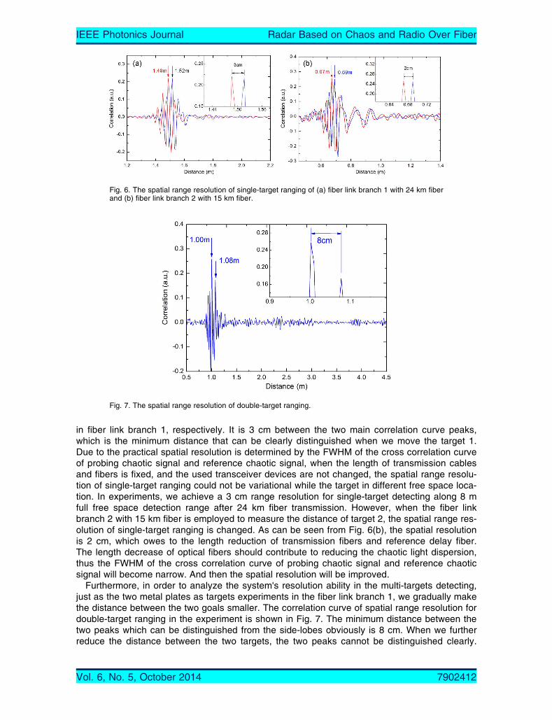
in fiber link branch 1, respectively. It is 3 cm between the two main correlation curve peaks,which is the minimum distance that can be clearly distinguished when we move the target 1.Due to the practical spatial resolution is determined by the FWHM of the cross correlation curveof probing chaotic signal and reference chaotic signal, when the length of transmission cablesand fibers is fixed, and the used transceiver devices are not changed, the spatial range resolu-tion of single-target ranging could not be variational while the target in different free space loca-tion. In experiments, we achieve a 3 cm range resolution for single-target detecting along 8 mfull free space detection range after 24 km fiber transmission. However, when the fiber linkbranch 2 with 15 km fiber is employed to measure the distance of target 2, the spatial range res-olution of single-target ranging is changed. As can be seen from Fig. 6(b), the spatial resolutionis 2 cm, which owes to the length reduction of transmission fibers and reference delay fiber.The length decrease of optical fibers should contribute to reducing the chaotic light dispersion,thus the FWHM of the cross correlation curve of probing chaotic signal and reference chaoticsignal will become narrow. And then the spatial resolution will be improved.
Furthermore, in order to analyze the system's resolution ability in the multi-targets detecting,just as the two metal plates as targets experiments in the fiber link branch 1, we gradually makethe distance between the two goals smaller. The correlation curve of spatial range resolution fordouble-target ranging in the experiment is shown in Fig. 7. The minimum distance between thetwo peaks which can be distinguished from the side-lobes obviously is 8 cm. When we furtherreduce the distance between the two targets, the two peaks cannot be distinguished clearly.
Fig. 6. The spatial range resolution of single-target ranging of (a) fiber link branch 1 with 24 km fiberand (b) fiber link branch 2 with 15 km fiber.
Fig. 7. The spatial range resolution of double-target ranging.
Vol. 6, No. 5, October 2014 7902412
IEEE Photonics Journal Radar Based on Chaos and Radio Over Fiber
This is because when the two targets are close to each other, the main peak and the side-lobesof the correlation curve will both approach each other. The main peak will be covered when theside-lobes superpose on each other in the same position and they will be higher than the mainpeak. As a result, the peaks cannot be distinguished clearly. Therefore, we get an 8 cm resolu-tion for the double-target detecting of the system experimentally.
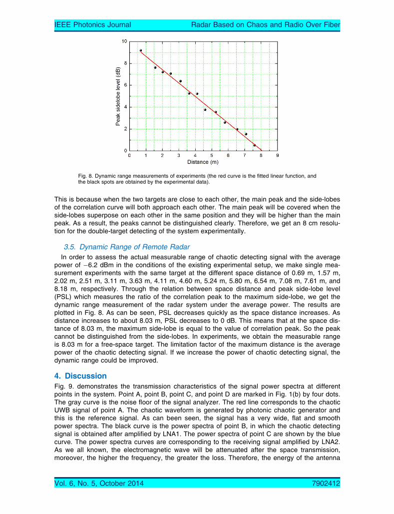
3.5. Dynamic Range of Remote RadarIn order to assess the actual measurable range of chaotic detecting signal with the average
power of �6.2 dBm in the conditions of the existing experimental setup, we make single mea-surement experiments with the same target at the different space distance of 0.69 m, 1.57 m,2.02 m, 2.51 m, 3.11 m, 3.63 m, 4.11 m, 4.60 m, 5.24 m, 5.80 m, 6.54 m, 7.08 m, 7.61 m, and8.18 m, respectively. Through the relation between space distance and peak side-lobe level(PSL) which measures the ratio of the correlation peak to the maximum side-lobe, we get thedynamic range measurement of the radar system under the average power. The results areplotted in Fig. 8. As can be seen, PSL decreases quickly as the space distance increases. Asdistance increases to about 8.03 m, PSL decreases to 0 dB. This means that at the space dis-tance of 8.03 m, the maximum side-lobe is equal to the value of correlation peak. So the peakcannot be distinguished from the side-lobes. In experiments, we obtain the measurable rangeis 8.03 m for a free-space target. The limitation factor of the maximum distance is the averagepower of the chaotic detecting signal. If we increase the power of chaotic detecting signal, thedynamic range could be improved.
4. DiscussionFig. 9. demonstrates the transmission characteristics of the signal power spectra at differentpoints in the system. Point A, point B, point C, and point D are marked in Fig. 1(b) by four dots.The gray curve is the noise floor of the signal analyzer. The red line corresponds to the chaoticUWB signal of point A. The chaotic waveform is generated by photonic chaotic generator andthis is the reference signal. As can been seen, the signal has a very wide, flat and smoothpower spectra. The black curve is the power spectra of point B, in which the chaotic detectingsignal is obtained after amplified by LNA1. The power spectra of point C are shown by the bluecurve. The power spectra curves are corresponding to the receiving signal amplified by LNA2.As we all known, the electromagnetic wave will be attenuated after the space transmission,moreover, the higher the frequency, the greater the loss. Therefore, the energy of the antenna
Fig. 8. Dynamic range measurements of experiments (the red curve is the fitted linear function, andthe black spots are obtained by the experimental data).
Vol. 6, No. 5, October 2014 7902412
IEEE Photonics Journal Radar Based on Chaos and Radio Over Fiber

received signal decreases as the signal frequency increases. In addition, due to the space elec-tromagnetism interference, not only the detecting signal which carries the target location infor-mation, but also the electromagnetic interference such as the cell phone signal are received byRA. The power spectra at point D are illustrated by the green curve. The final detecting signal issampled and stored by OSC. Limited by the 10 GHz modulation bandwidth of LD, the chaoticUWB signal bandwidth at point D is much narrower than it at point B. The target detecting is ac-complished through the cross correlation between the detecting signal and the reference signal.As can be seen, although the detecting signal is so distorted, the proposed system has a goodrange performance according to the ranging results shown in Figs. 3 and 4. The spectra band-width of the reference signal (point A) and the detecting signal (point D) are different due to thelimitation of the 10 GHz modulation bandwidth of LD, that means the waveform of detecting sig-nal suffer the distortion. Although its waveform widen and attenuate, the characteristics of cha-otic signal mostly reserves, and then the cross correlation curve between the waveform timeseries of the reference signal and the detecting signal still has good quality to identify the dis-tance. That owes to the chaotic signal has the excellent autocorrelation characteristic and anti-jamming ability.
In the system of the microwave-photonic chaotic UWB radar system for remote ranging, thechaotic signal with a bandwidth of 18 GHz is generated by photonic chaotic generator, but thebandwidth of the real-time oscilloscope used in the experiment is only 6 GHz, this means thatthe signal is low pass filtered by the front end of the oscilloscope. So a limited ranging resolutionof 0.6 cm for the system is achieved. However, due to the effect of interfering signals in spaceand the dispersion effect, we can only attain a spatial range resolution of 3 cm. Better range res-olution can be achieved by using a high bandwidth oscilloscope and a high-speed modulator forLD. The FWHM of the autocorrelation trace is 5.3 cm with a 1 GHz acquisition bandwidth, so alimit range resolution of 5.3 cm is achieved. We also get the special range resolution of 1.2 cm,0.9 cm and 0.6 cm when the acquisition bandwidth of the system increases to 3 GHz, 4 GHzand 6 GHz, respectively. The results are shown in Fig. 10. As can be seen, the wider the band-width of the chaotic signal is, the narrower the FWHM of autocorrelation function becomes, andthe higher the spatial resolution can be reached.
As mentioned in [3], for short-range high-speed wireless communication, the UWB signalsare generally in impulse-radio (IR) form or multiband (MB) form generated in electronic domain.By wireless transmission, UWB signals can only transmit over a short distance from a fewmeters to tens of meters. For enlarging the coverage area and supporting the availability ofundisrupted service across different networks, the convergence of UWB signals and optical
Fig. 9. The power spectra characteristics of different points in the system. Point A, point B, point C,and point D are marked in Fig. 1 by four dots.
Vol. 6, No. 5, October 2014 7902412
IEEE Photonics Journal Radar Based on Chaos and Radio Over Fiber

fiber distribution techniques, the so-called UWB-over-fiber, has been proposed. In order to dis-tribute UWB signals over the optical fiber, it is highly desirable that the UWB signals can begenerated directly in the optical domain. So, in this paper, in order to construct the antennaremote control ranging radar system, we used the microwave-photonic approach to generatethe UWB signal, and then we can realize the microwave-photonic remote radar based on chaosgeneration in optical domain and UWB-over-fiber. This system can not be achieved only byusing the method in [3].
Compared with [17], in our paper, not only the chaotic light generation is different that thebandwidth enhancement by the optical feedback, but also, more important, we utilize the fiber-optic distribution technology to realize the remoting control of radar antenna. In other words, thismicrowave-photonic chaotic UWB radar system combines the chaotic radar using nonlinearlaser dynamics as in [17] with the UWB-over-fiber technology, not only gains a high rangingresolution, but also implements the antenna remote control.
In [29], a microwave-photonic UWB noise radar system is proposed and demonstrated. TheUWB noise waveform is generated using the amplified spontaneous emission that is associatedwith either stimulated Brillouin scattering in a standard optical fiber, or with erbium-doped fiberamplification. Waveforms of more than 1-GHz bandwidth and arbitrary radio-frequency carriersare generated, and distributed over 10-km fiber to a remote antenna unit. The authors demon-strated ranging measurements with 10-cm and 20-cm resolution after 10-km fiber transmission.In [32], Zheng et al. proposed and demonstrated a novel fiber-distributed chaotic UWB noiseradar, which consists of a chaotic UWB noise source based on optoelectronic oscillator, a fiber-distributed transmission link, a colorless base station, and a cross-correlation processingmodule. Especially, the power spectrum of chaotic UWB signal could be shaped and notch-filtered to avoid the spectrum-overlay-induced interference to the narrow band signals. Mean-while, the wavelength-reusing could be implemented by means of the distributed polarizationmodulation-to-intensity modulation conversion. By this excellent method, the space resolution ofthe proposed radar is up to cm-level as the probing signal is delivered over a length of 3-kmSMF. Compared with these works, we obtain the higher spatial resolution and longer fiber distri-bution in remote ranging, which thanks to the bandwidth enhancement chaotic signal generationby an optical injection laser diode with optical feedback. And we also construct a microwave-photonic chaotic UWB array radar system, which contains more than one remote antenna unit.By using two 1 : N optical switch, the probing signal and its corresponding echoed signal canbe distributed to different fiber link branch to construct multi-remoting-antenna units. That meanswe could only use a set of transmitter and receiver in central office to realize different targetremote ranging in different areas.
Fig. 10. The relationship between FWHM and bandwidth.
Vol. 6, No. 5, October 2014 7902412
IEEE Photonics Journal Radar Based on Chaos and Radio Over Fiber

5. ConclusionA microwave-photonic remote radar based on chaos generation and radio over fiber is demon-strated. Compared with conventional radars, the proposed radar not only realizes the remotecontrol of the radar, but also has a high range resolution. In this paper, the characteristics of thedetecting signal, the performance of single-target ranging and double-targets ranging, the dyna-mic range and the spatial range resolution of the remote radar system are studied experimen-tally. And we also discuss the strong anti-jamming ability of the system. Using the chaotic signalgenerated by an optically injected semiconductor laser with optical feedback as the detectingsignal of the radar, it is the noise characteristic and wide bandwidth of the chaotic signal thatmakes the autocorrelation properties good. By using two 1 : 2 optical switch, the probing signaland its corresponding echoed signal are distributed to different fiber link branch to constructmulti-remoting-antenna units. In the fiber link branch 1, the range resolution of 3 cm for single-target ranging and 8 cm for double-targets ranging are achieved for distance up to 8 m throughthe remote control with two 24 km single mode fibers experimentally. In the fiber link branch 2with 15 km fiber transmission, a 2 cm spatial resolution for single target detecting is obtained.This remote radar system can be used for military radar, hilltops under bad conditions, theradar systems of islands, dangerous areas, and harsh industrial environments.
References[1] G. R. Aiello and G. D. Rogerson, “Ultra-wideband wireless systems,” IEEE Microw. Mag., vol. 4, no. 2, pp. 36–47,
Jun. 2003.[2] D. Porcino and W. Hirt, “Ultra-wideband radio technology: Potential and challenges ahead,” IEEE Commun. Mag.,
vol. 41, no. 7, pp. 66–74, Jul. 2003.[3] L. Q. Yang and G. B. Giannakis, “Ultra-wideband communications: An idea whose time has come,” IEEE Signal
Process. Mag., vol. 21, no. 6, pp. 26–54, Nov. 2004.[4] S. Roy, J. R. Foerster, V. S. Somayazulu, and D. G. Leeper, “Ultrawideband radio design: The promise of high-
speed, short-range wireless connectivity,” Proc. IEEE, vol. 92, no. 2, pp. 295–311, Feb. 2004.[5] J. Han and C. Nguyen, “Development of a tunable multiband UWB radar sensor and its applications to subsurface
sensing,” IEEE Sensors J., vol. 7, no. 1, pp. 51–58, Jan. 2007.[6] V. Venkatasubramanian, H. Leung, and X. X. Liu, “Chaos UWB radar for through-the-wall imaging,” IEEE Trans. Im-
age Process., vol. 18, no. 6, pp. 1255–1265, Jun. 2009.[7] R. M. Narayanan, “Through-wall radar imaging using UWB noise waveforms,” J. Franklin Inst., vol. 345, no. 6,
pp. 659–678, Sep. 2008.[8] H. Liu, H. Darabi, P. Banerjee, and J. Liu, “Survey of wireless indoor positioning techniques and systems,” IEEE
Trans. Syst., Man, Cybern. C, Appl. Rev., vol. 37, no. 6, pp. 1067–1080, Nov. 2007.[9] S. Gezici et al., “Localization via ultra-wideband radios: A look at positioning aspects for future sensor networks,”
IEEE Signal Process. Mag., vol. 22, no. 4, pp. 70–84, Jul. 2005.[10] J. Y. Lee and R. A. Scholtz, “Ranging in a dense multipath environment using an UWB radio link,” IEEE J. Sel.
Areas Commun., vol. 20, no. 9, pp.1677–1683, Dec. 2002.[11] W. C. Chung and D. S. Ha, “An accurate ultra wideband (UWB) ranging for precision asset location,” in Proc. IEEE
Conf. Ultra Wideband Syst. Technol., Nov. 2003, pp. 389–393.[12] Z. N. Low, J. H. Cheong, C. L. Law, W. T. Ng, and Y. J. Lee, “Pulse detection algorithm for line-of-sight (LOS) UWB
ranging applications,” IEEE Antennas Wireless Propag. Lett., vol.4, pp. 63–67 Jun. 2005.[13] H. B. Sun, Y. L. Lu, and G. S. Liu, “Ultra-wideband technology and random signal radar: An ideal combination,”
IEEE Aerosp. Electron. Syst. Mag., vol. 18, no. 11, pp. 3–7, Nov. 2003.[14] R. M. Narayanan, Y. Xu, P. D. Hoffmeyer, and J. O. Curtis, “Design, performance, and applications of a coherent
ultra-wideband random noise radar,” Opt. Eng., vol. 37, no. 6, pp. 1855–1869, Feb. 1998.[15] S. Qiao et al., “A new architecture of UWB radar utilizing microwave chaotic signals and chaos synchronization,”
Progr. Electromagn. Res., vol. 75, pp. 225–237, 2007.[16] T. Jiang et al., “Simulation and experimental evaluation of the radar signal performance of chaotic signals generated
from a microwave Colpitts oscillator,” Progr. Electromagn. Res., vol. 90, pp. 15–30, 2009.[17] F. Y. Lin and J. M. Liu, “Chaotic radar using nonlinear laser dynamics,” IEEE J. Quantum Electron., vol. 40, no. 6,
pp. 815–820, Jun. 2004.[18] J. P. Yao, F. Zeng, and Q. Wang, “Photonic generation of ultrawideband signals,” J. Lightw. Technol., vol. 25, no. 11,
pp. 3219–3235, Nov. 2007.[19] M. Ran, B. I. Lembrikov, and Y. B. Ezra, “Ultra-wideband radio-over-optical fiber concepts, technologies and applica-
tions,” IEEE Photon. J., vol. 2, no. 1, pp. 36–48, Feb. 2010.[20] J. Y. Zheng et al., “Implementation of wavelength reusing upstream service based on distributed intensity conversion
in ultrawideband-over-fiber system,” Opt. Lett., vol. 38, no. 7, pp. 1167–1169, Apr. 2013.[21] P. Zhao et al., “In-line polarization-dependent microfiber interferometers and their applications in UWB signal genera-
tion,” Opt. Exp., vol. 21, no. 7, pp. 8231–8239, Apr. 2013.
Vol. 6, No. 5, October 2014 7902412
IEEE Photonics Journal Radar Based on Chaos and Radio Over Fiber

[22] P. X. Li et al., “Photonic generation and transmission of 2-Gbit/s power-efficient IR-UWB signals employing an elec-tro-optic phase modulator,” IEEE Photon. Technol. Lett., vol. 25, no. 2, pp. 144–146, Jan. 2013.
[23] W. Li, L. X. Wang, W. Hofmann, N. H. Zhu, and D. Bimberg, “Generation of ultra-wideband triplet pulses based onfour-wave mixing and phase-to-intensity modulation conversion,” Opt. Exp., vol. 20, no. 18, pp. 20 222–20 227,Aug. 2012.
[24] K. Tan et al., “Photonic-chip-based all-optical ultra-wideband pulse generation via XPM and birefringence in a chal-cogenide waveguide,” Opt. Exp., vol. 21, no. 2, pp. 2003–2011, Jan. 2013.
[25] M. J. Zhang et al., “Photonic generation of ultrawideband signals based on a gain-switched semiconductor laserwith optical feedback,” Appl. Opt., vol. 52, no. 31, pp. 7512–7516, Nov. 2013.
[26] Y. Peled, M. Tur, and A. Zadok, “Generation and detection of ultra-wideband waveforms using stimulated Brillouinscattering amplified spontaneous emission,” IEEE Photon. Technol. Lett., vol. 22, no. 22, pp. 1692–1694, Nov. 2010.
[27] M. J. Zhang et al., “Photonic ultrawideband signal generator using an optically injected chaotic semiconductor laser,”Opt. Lett., vol. 36, no. 6, pp. 1008–1010, Mar. 2011.
[28] J. Y. Zheng et al., “Photonics-assisted ultra-wideband pulse generator with tunable notch filtering based onpolarization-to-intensity conversion,” IEEEE Photon. J., vol. 5, no. 3, pp. 7900909, Jun. 2013.
[29] D. Grodensky, D. Kravitz, and A. Zadok, “Ultra-wideband microwave-photonic noise radar based on optical wave-form generation,” IEEE Photon. Technol. Lett., vol. 24, no. 10, pp. 839–841, May 2012.
[30] Y. N. Ji and M. J. Zhang, “Ultra-wideband microwave-photonic chaotic radar for remote ranging,” in Proc. 12thICOCN, Jul. 2013, pp. 1–3.
[31] Y. N. Ji et al., “Microwave-photonic sensor for remote water-level monitoring based on chaotic laser,” Int. J. Bifurcat.Chaos, vol. 24, no. 3, pp. 1450032, Mar. 2014.
[32] J. Y. Zheng et al., “Fiber-distributed ultra-wideband noise radar with steerable power spectrum and colorless basestation,” Opt. Exp., vol. 22, no. 5, pp. 4896–4907, Jan. 2014.
[33] Y. C. Wang, B. J. Wang, and A. B. Wang “Chaotic correlation optical time domain reflectometer utilizing laser diode,”IEEE Photon. Technol. Lett., vol. 20, no. 19, pp. 1636–1638, Oct. 2008.
[34] A. B. Wang et al., “Precise fault location in WDM-PON by utilizing wavelength tunable chaotic laser,” J. Lightw.Technol., vol. 30, no. 21, pp. 3420–3426, Nov. 2012.
Vol. 6, No. 5, October 2014 7902412
IEEE Photonics Journal Radar Based on Chaos and Radio Over Fiber