rendering of stereoscopic 360 views from spherical image pairs · pdf filerendering of...
TRANSCRIPT

Rendering of Stereoscopic 360◦ Views from Spherical Image Pairs
Dash Bodington, Jayant Thatte, Matthew Hu{dashb, jayantt, matthu}@stanford.edu
Department of Electrical Engineering, Stanford University
June 5, 2015
AbstractIn this work, a technique for rendering stereoscopic 360◦
images from a pair of spherical images, for virtual realityapplications, is presented. The spherical images are capturedusing a Ricoh Theta1 camera from two viewpoints separatedby a known, vertical displacement. Using vertical, ratherthan horizontal, camera displacement allows the computationof depth information in all viewing directions, except zenithand nadir, which is crucial for rendering an omnidirectionalstereo view. Stereo correspondence information from a three-dimensional similarity accumulator is combined with theRGB information in the captured images to produce dense,noise-free disparity maps that preserve edge information.From cleaned disparity maps, depth information is calculatedfrom disparity and pixels are remapped to a new viewpoint inwhich artifacts are filled before display on a Samsung GearVR 2. Using our method high quality stereo images can berendered with a reasonably good perceived depth.
1 IntroductionDepth-based stereoscopic image rendering and 3Dreconstruction has been an important area of research inmultimedia, broadcasting and in computer vision. Thearea has received a lot of attention from the broadcastresearch community for its applications in 3D television(TV) [1], [2]. Whereas the classical approach to 3D TVrequires the transmission of two video streams, the depth-based approach can achieve the result using only one videostream and one stream of depth maps, thus rendering 3Dcontent using a smaller bandwidth [3], [4]. Similarly,depth-based 3D perception is an important pre-requisite forapplications in computer vision and virtual and augmentedreality [5], [6], [7].
The remainder of this report is structured as follows.Section 2 gives an overview of the equipment used for theproject and its setup. Section 3 talks about the algorithmsused for pixel-level, raw disparity computation and the
1https://theta360.com/uk/2http://www.samsung.com/global/microsite/gearvr/
various post-processing techniques used to generate the finaldisparity map. Section 4 gives a brief geometric descriptionof stereo view generation algorithm and then moves onto talk about the technique used for inpainting the newlyexposed areas due to disocclusion. Section 5 displays imagesat various stages in the processing pipeline and commentson the quality of the produced results. Section 6 outlinespossible improvements to the work done in this project andthe directions in which the work discussed in this report canbe extended in future.
2 Equipment Setup and Preprocessing
2.1 Equipment SetupPairs of images used for disparity calculation and stereo viewmanipulation were captured with a Ricoh Theta camera. TheRicoh Theta has two opposite-facing 185◦ fish-eye lenses andsensors. This captures a 360◦ by 180◦ image of a scene whenthe two images are stitched together by the Theta softwareinto an equirectangular image at a resolution of 1792 by3584 pixels.
Capturing each scene requires recording two of theseimages from viewpoints displaced vertically by a knowndistance. The displacement must be sufficient to causeobjects at selected depths to move one pixel or more, butlarge shifts can be problematic because objects are distortedas they move, and smaller pixel shifts can be calculatedfaster. Once processing is performed in MATLAB 3, thefinal stereo views are loaded onto the Samsung Gear VR, avirtual reality headset which houses a Samsung Galaxy S6 asa display. The device keeps track of the direction its wearer isfacing and displays the correct image to create an immersivestereoscopic 360◦ experience.
2.2 PreprocessingThe image captured using the setup described above need tobe aligned to account for possible horizontal translation androtation of one viewpoint with respect to the other. Since
3http://www.mathworks.com/products/matlab/
1
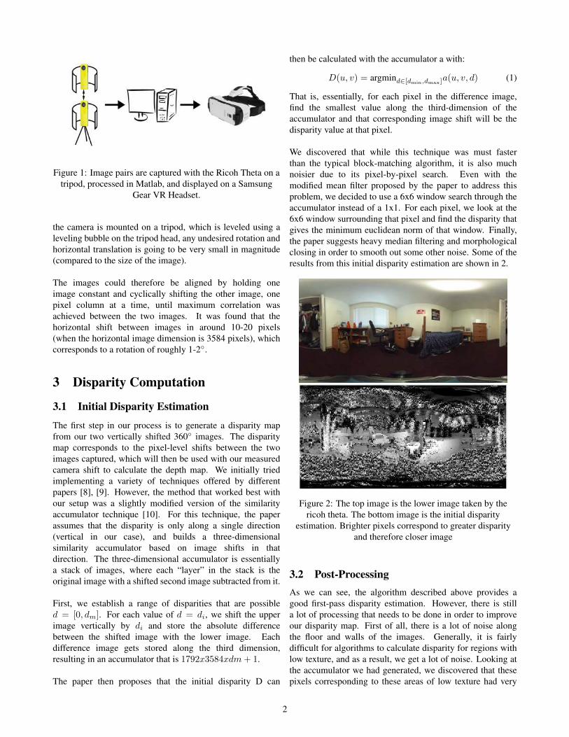
Figure 1: Image pairs are captured with the Ricoh Theta on atripod, processed in Matlab, and displayed on a Samsung
Gear VR Headset.
the camera is mounted on a tripod, which is leveled using aleveling bubble on the tripod head, any undesired rotation andhorizontal translation is going to be very small in magnitude(compared to the size of the image).
The images could therefore be aligned by holding oneimage constant and cyclically shifting the other image, onepixel column at a time, until maximum correlation wasachieved between the two images. It was found that thehorizontal shift between images in around 10-20 pixels(when the horizontal image dimension is 3584 pixels), whichcorresponds to a rotation of roughly 1-2◦.
3 Disparity Computation
3.1 Initial Disparity Estimation
The first step in our process is to generate a disparity mapfrom our two vertically shifted 360◦ images. The disparitymap corresponds to the pixel-level shifts between the twoimages captured, which will then be used with our measuredcamera shift to calculate the depth map. We initially triedimplementing a variety of techniques offered by differentpapers [8], [9]. However, the method that worked best withour setup was a slightly modified version of the similarityaccumulator technique [10]. For this technique, the paperassumes that the disparity is only along a single direction(vertical in our case), and builds a three-dimensionalsimilarity accumulator based on image shifts in thatdirection. The three-dimensional accumulator is essentiallya stack of images, where each “layer” in the stack is theoriginal image with a shifted second image subtracted from it.
First, we establish a range of disparities that are possibled = [0, dm]. For each value of d = di, we shift the upperimage vertically by di and store the absolute differencebetween the shifted image with the lower image. Eachdifference image gets stored along the third dimension,resulting in an accumulator that is 1792x3584xdm+ 1.
The paper then proposes that the initial disparity D can
then be calculated with the accumulator a with:
D(u, v) = argmind∈[dmin,dmax]a(u, v, d) (1)
That is, essentially, for each pixel in the difference image,find the smallest value along the third-dimension of theaccumulator and that corresponding image shift will be thedisparity value at that pixel.
We discovered that while this technique was must fasterthan the typical block-matching algorithm, it is also muchnoisier due to its pixel-by-pixel search. Even with themodified mean filter proposed by the paper to address thisproblem, we decided to use a 6x6 window search through theaccumulator instead of a 1x1. For each pixel, we look at the6x6 window surrounding that pixel and find the disparity thatgives the minimum euclidean norm of that window. Finally,the paper suggests heavy median filtering and morphologicalclosing in order to smooth out some other noise. Some of theresults from this initial disparity estimation are shown in 2.
Figure 2: The top image is the lower image taken by thericoh theta. The bottom image is the initial disparity
estimation. Brighter pixels correspond to greater disparityand therefore closer image
3.2 Post-ProcessingAs we can see, the algorithm described above provides agood first-pass disparity estimation. However, there is stilla lot of processing that needs to be done in order to improveour disparity map. First of all, there is a lot of noise alongthe floor and walls of the images. Generally, it is fairlydifficult for algorithms to calculate disparity for regions withlow texture, and as a result, we get a lot of noise. Looking atthe accumulator we had generated, we discovered that thesepixels corresponding to these areas of low texture had very
2

low variance across the disparity axis in the accumulator. Wetherefore made a search through each pixel in the accumulatorand zeroed out all disparities corresponding to low varianceacross the third-dimension of the accumulator. This removeda lot of the noise in the image shown 3.
Figure 3: The disparity map with the noisy regions zeroedout. The disparity map now appears a lot cleaner
Median filtering and morphological closing earlier removedsome of the smaller holes in the image, but there are stilllarge undefined regions due to the noise removal. Weperformed region labeling for all of the undefined regions ofthe disparity map and classified them according to their size.For smaller regions, we simply filled them in by averagingthe pixel values along their borders. This was accomplishedby performing morphological edge detection on each of theundefined regions to get an outer edge, and then averagingover the disparity values corresponding to that border. Thismethod works because most of the small holes are generallyfrom the un-textured regions of a single object. Therefore byaveraging over the border disparity values, we generally getobjects with consistent disparity values.
For larger regions, we followed the method outlinedin [10] by looking along the scan lines and only usingdisparity values directly above and below the undefinedregion to fill in the holes. To implement this, we essentiallybroke each region into separate columns and filled in eachgroup of columns with the median of the bordering disparityvalues. Finally, we used a large horizontal blurring filter inorder to smooth out the sharp edges and filled in the largeholes with the result. The resulting images are shown 4.
Figure 4: The resulting disparity map with the undefinedregions filled in.
Overall, our disparity maps give a good estimate of the imageshift. In many of the images shown above, we can see agradient of the pixels gradually getting darker as the objectsget further away. We can also distinguish separate objectsfairly well and see disparity discontinuities between close andfar objects. The main problem with this disparity map is thatit is still somewhat noisy. Also, edges are not clearly defineddue to our closing filter to fill in holes. As a result, we neededfurther processing in order to improve this map.
3.3 Disparity Averaging based on Image Seg-mentation
The disparity map generated thus far, still has a considerablepixel-level noise rendering it unusable for any meaningfulstereo application. Most simple low pass filtering operationsfail to preserve sharp edges and discontinuities in thedisparity. Hence, segmentation-based averaging was used tosmooth the generated disparity map.
In this novel technique, the image is first segmentedusing RGB data in the image using a modified version ofDensity-Based Spatial Clustering of Applications with Noise(DBSCAN). The advantage of this technique is that it canform arbitrarily shaped, connected segments based on thecolor information. An image is split into several thousandsuch segments and disparity values are averaged over eachsegment. Since the segmentation is based on the image color,edge information is preserved very well. Similarly, havinga large number of segments ensures that each object in theimage is comprised of several segments, which helps inpreserving disparity gradients across objects.
At the end of this step, the disparity map is noise-freeand still preserves the edge information very well. This isthe final version of the disparity map, which will be usedfurther, for rendering stereo views. Below are sample resultsfrom this stage. It can be seen that even though all thepixel-level noise is removed, the disparity gradient across thebed is still preserved and sharp discontinuities in disparity aremaintained.
4 Stereo View Rendering
Before new views can be rendered, simple processing mustbe done to the disparity to convert it to distance, and smoothit slightly. Knowing camera displacement between thecaptured images allows the conversion of disparity values toaccurate distances from the camera. Once distance valuesare calculated, the RGBD equirectangular image containsinformation for every pixel on both color and spatial positionin spherical coordinates.
3

Figure 5: The top image is the room segmented by color. Thebottom image is the resulting disparity map after averaging
the segmented sections.
4.1 Viewpoint Geometries
In order to produce a stereoscopic scene, imagetransformations based on depth information must beperformed. These transformations can be of two types,realistic transformations, and pseudo transformations. Thegoal of both is to produce pairs of images which appear3D, but a realistic transformation is incompatible witha display device such as an Oculus or Samsung Gear VR,which only accepts two equirectangular images per 360 scene.
In a realistic environment, the parallax shift of objectsis a function of angular position, horizontally. There is noparallax effect, for example, at 90 degrees from the directiona person is facing. If an image like this was put into anOculus device, it could not be immersive because a 90 degreehead turn would face the user toward a region of no parallax,while he would have maximum parallax in peripheral vision.This project implemented this realistic 3D view generation,but a different geometry was used to generate display viewsfor the Oculus device.
Because the VR headset only displays one 360 imagefor each eye, the movement of every object, regardless ofhorizontal position, is calculated as if the object was in thecenter of the visual field. This approximation still producesquality 3D views because object shifts always appear correctin the center of the subjects visual field, and as visual acuityfalls off away from the center, it is harder to tell that offsetsare not realistically rendered.
4.2 Inpainting
Because producing stereoscopic views is a depth-basedremapping of all pixel values, it is likely that some areas inthe generated view will be empty. These image gaps needto be filled to make the image acceptable. There are manyways to fill these holes in the image, but because the goalis to make the image look realistic and to preserve sharpedges on shifted foreground objects, this project used adepth-sensitive content mirroring operation to add contentto holes. This method is relatively simple compared tosome content generation inpainting techniques, but workssufficiently well to avoid noticeable image artifacts instandard (non-translated) stereoscopic rendering [11]. Unlikemost inpainting tasks, however, we have knowledge of depth,and want to preserve discontinuity on one side of the holewhere the boundary of an object is.
To fill holes, the image is scanned line by line. Whenthe beginning of a hole is encountered, its length on the lineis calculated, and the depths of the pixels bounding the holeare compared. To preserve the discontinuity at the closeend of the hole and blend with the further end, informationfrom the deeper side is mirrored into the hole. This processis performed line-by-line for the entire image, and is thenperformed column-by-column in a similar manner so thatholes are filled with an average of mirrored information fromtheir deeper vertical and horizontal edges.
This process works well when holes are small, however,creating large holes can be problematic because it becomesobvious that information has been copied. Stereoscopicviews usually contain holes which are not noticeable whenfilled, but translated views are more distorted and containmore holes which are harder to discretely fill.
4.3 Translated Views
Though generating stereo images involves translated view-points, this project also produced stereoscopic views whosecentral position was different from the camera position. Ren-dering a translated view, as if the stereo views were generatedfrom a translated camera, is slightly more difficult than asimple stereoscpoic view. Before performing stereoscopicview generation, all pixel positions are calculated in cartesiancoordinates so that they can be modified according to the newimaginary camera position, and then are transformed backto spherical coordinates where the pseudo view generation issimpler, and remapping is more straightforward. When gen-erating true (realistic) stereoscopic views, all pixel locationchanges are done in cartesian coordinates because the entireremapping can be done in one step.
4

5 Results
Figure 6: Images from top to bottom: original lower image,segmented disparity map, depth map, left view, and right
view.
Figure 7: Images from top to bottom: original lower image,segmented disparity map, depth map, left view, and right
view.
5

Figure 8: Images from top to bottom: original lower image,segmented disparity map, depth map, left view, and right
view.
The stereo images rendered using our method are of goodquality and contain minimal inpainting and disparity artifacts.The images also produce a reasonably good perceived depth.The image produced do have some geometric distortions. A
possible cause for this could be the high geometric distortionintroduced by the fish-eye lenses in Ricoh Theta, which hasnot been compensated for, in this project. It is expected thatrunning camera calibration and lens undistortion algorithmsprior to using our method will produce better results.
Another challenge is that since our camera displacement isvertical, it is hard to estimate depth information of verticalobjects such as pillars, that have no texture along the verticaldirection. Similarly, by the virtue of the equipment setup,there cannot be any disparity information along the baselinei.e. towards zenith and nadir. This is, however, generally notan issue, since most human observers looking at an imagetend to focus on image regions within a band around theequator, and two-image 360◦ VR views are not capable ofdisplaying depth at angles near the poles.
6 Future WorkWhile this project successfully demonstrated a capture-to-display stereoscopic 360◦ system, there is a great deal ofimprovement which can still be done. The current systemuses one camera which is moved between photos, butattaching two Ricoh Theta cameras and triggering themtogether would allow for live scene capture with compacthardware, a more elegant solution than current conceptswhich rely on large assemblies of many cameras.
Processing is likely the area in which the greatest amount ofimprovement could be made. Disparity calculations may beimproved by taking into account camera distortion duringmatching, better filtering could reduce artifacts in disparitywith less distortion, and improved inpainting methodswould make larger translations from the camera positionpossible. Processing speed is also an area in which significantimprovement is necessary.
Another possible extension is to add the effect of livemodification of view with translation by pre-computing astack of images and pulling the right image into the displaybased on the VR translation output, or posiibly computingon-the-fly, should such a processing speed be achieved.
Improvements in the processing would open up a largenumber of possibilities in entertainment, such as stereoscopic360◦ video in which the viewer is able to look around andmake small head movements.
References[1] L. Zhang and W. J. Tam, “Stereoscopic image generation
based on depth images for 3d tv,” Broadcasting, IEEETransactions on, vol. 51, no. 2, pp. 191–199, June 2005.
[2] G. Thomas and O. Grau, “3d image sequence acqui-sition for tv & film production,” in 1st International
6

Symposium on 3D Data Processing Visualization andTransmission, 2002, pp. 320–326.
[3] J. Flack, P. Harman, and S. Fox, “Low bandwidthstereoscopic image encoding and transmission,” in Pro-ceedings of SPIE-IS&T Electronic Imaging, 2003, pp.206–214.
[4] C. Fehn, “Depth-image-based rendering (dibr),compression, and transmission for a new approachon 3d-tv,” pp. 93–104, 2004. [Online]. Available:http://dx.doi.org/10.1117/12.524762
[5] H. Kim and A. Hilton, “3d scene reconstruction frommultiple spherical stereo pairs,” International Journalof Computer Vision, vol. 104, no. 1, pp. 94–116,2013. [Online]. Available: http://dx.doi.org/10.1007/s11263-013-0616-1
[6] H. Kim, M. Sarim, T. Takai, J.-Y. Guillemaut, andA. Hilton, “Dynamic 3d scene reconstruction in outdoorenvironments,” in 3DPVT, 2010, <p>Copyright 2010IEEE. Personal use of this material is permitted.However, permission to reprint/republish this materialfor advertising or promotional purposes or for creatingnew collective works for resale or redistributionto servers or lists, or to reuse any copyrightedcomponent of this work in other works must beobtained from the IEEE.</p>. [Online]. Available:http://epubs.surrey.ac.uk/110210/
[7] M. Schonbein and A. Geiger, “Omnidirectional 3d re-construction in augmented manhattan worlds,” in Intel-ligent Robots and Systems (IROS 2014), 2014 IEEE/RSJInternational Conference on, Sept 2014, pp. 716–723.
[8] K.-H. Bae, D.-S. Yi, S. C. Kim, and E.-S. Kim, “A bi-directional stereo matching algorithm based on adaptivematching window,” in Applications of Digital ImageProcessing XXVIII, ser. Society of Photo-Optical Instru-mentation Engineers (SPIE) Conference Series, A. G.Tescher, Ed., vol. 5909, Aug. 2005, pp. 676–683.
[9] H. Kim and K. Sohn, “Hierarchical depth estimationfor image synthesis in mixed reality,” pp. 544–553,2003. [Online]. Available: http://dx.doi.org/10.1117/12.473879
[10] J. Schmidt, H. Niemann, and S. Vogt, “Dense disparitymaps in real-time with an application to augmented real-ity,” in Applications of Computer Vision, 2002. (WACV2002). Proceedings. Sixth IEEE Workshop on, 2002, pp.225–230.
[11] A. Criminisi, P. Perez, and K. Toyama, “Region fillingand object removal by exemplar-based image inpaint-ing,” Image Processing, IEEE Transactions on, vol. 13,no. 9, pp. 1200–1212, Sept 2004.
A Team RolesDash Bodington: Focused primarily on post-disparitycalculations and processing. This includes disparity filtering,disparity to distance calculation, viewpoint geometries andpixel remapping, and inpainting. He also participated in teammeetings and material preparation.
Jayant Thatte: Focused on stages in the pipeline up toand including the generation of final disparity maps. Thisincluded initial aligning of images and computing rawdisparity maps as well as post-processing. Tried out acouple of different methods for computing raw disparity— Window-based disparity estimation and bidirectionaldisparity mapping [8], [9], which were later depreciatedin favor of accumulator-based disparity calculation. Also,implemented image segmentation based on RGB data andsegmentation-based disparity averaging to produce the finaldisparity maps.
Matthew Hu: Focused primarily on disparity mapcalculations. Generated initial disparity maps, workedon hole filling, and tested various techniques to improvemaps. Also worked with the rest of the team on setup, imagecapture, and poster/report preparation.
7