rendering techniques in 3d autocad part 1 - dscohn.comdscohn.com/au/handouts/gd111-3 rendering part...
TRANSCRIPT

1
Rendering Techniques in 3D AutoCAD®, Part 1David CohnIndependent Consultant

2
Please remember to fill out your evaluation form
This is session GD111‐3
Evaluation Forms
And, please silence your cell phone.

3
David S. CohnIndependent consultantContributing editor Desktop Engineeringcontributing editorFormer editor of CADalyst, Engineering Automation Report and CADCAMNetFrequent contributor to Computer Graphics World, PC Magazine, and othersRegistered architect—25+ years experienceAutoCAD experience—20+ yearsAuthor of numerous books & articlesPresident of Eclipse Software
4
David Cohn is a Registered Provider with The American Institute of Architects Continuing Education Systems. Credit earned on completion of this program will be reported to CES Records for AIA members. Certificates of Completion for non-AIA members are available on request.
This program is registered with the AIA/CES for continuing professional education. As such, it does not included content that may be deemed or construed to be an approval or endorsement by the AIA of any material of construction or any method or manner of handling, using, distributing, or dealing in any material or product. Questions related to specific materials, methods, and services will be addressed at the conclusion of this presentation.

5
Part 1 will cover:How rendering has changed from earlier versions of AutoCADWorking with lightsSun & Sky Background settingsWorking with Materials (including creating and modifying materials)
This is part 1 of a 2 part class

6
In part 2, we will cover:The Render control panel (incl. render destination, render procedure, and output resolution)Preparing your modelAdjusting rendering settingsPlacing cameras and creating viewsSaving rendered imagesCreating walkthroughs and flythroughs
Part 2 will follow this class from 3:15 – 4:45pm(here in this same room after a 30 minute break)
This is part 1 of a 2 part class

7
Rendering tools have existed in AutoCAD for many years, but remained largely unchanged since AutoCAD R12.Completely new beginning in AutoCAD 2007
Based on mental ray® rendering engine (same as Autodesk® VIZ and 3dsmax®
New commands make rendering easierAdditional new commands to walk or fly through models
Rendering in AutoCADCreating a 2D image based on your 3D scene

8
Can display models with realistic materials, lighting, and shadows
Depends on the current active visual style
Visual style – a collection of settings that control the display of edges and shading in the viewport
AutoCAD comes with five pre‐defined visual styles2D wireframe3D wireframe3D hiddenConceptualRealisticYou can create and save your own
New beginning in AutoCAD 2007
9
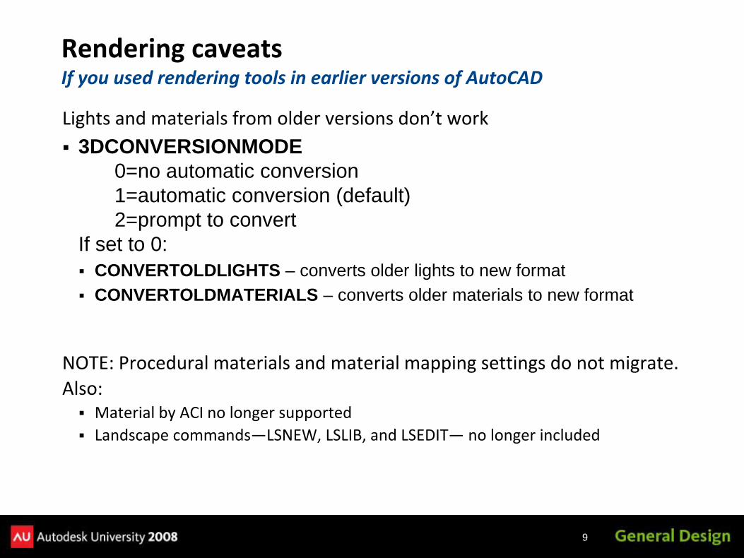
Lights and materials from older versions don’t work3DCONVERSIONMODE
0=no automatic conversion1=automatic conversion (default)2=prompt to convert
If set to 0:CONVERTOLDLIGHTS – converts older lights to new formatCONVERTOLDMATERIALS – converts older materials to new format
NOTE: Procedural materials and material mapping settings do not migrate.Also:
Material by ACI no longer supportedLandscape commands—LSNEW, LSLIB, and LSEDIT— no longer included
Rendering caveatsIf you used rendering tools in earlier versions of AutoCAD

10
Time consuming: you can spend a lot of time adjusting lighting and materialsYou may spend more time creating the rendering than building the modelMultiple light sources and shadows require fast computersYou can speed things by first rendering test images on a portion of the model
Creating Rendered Images
11
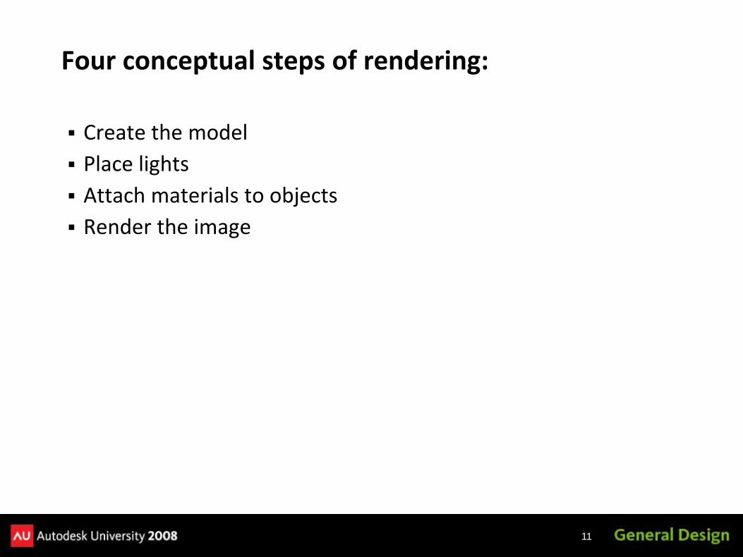
Create the modelPlace lightsAttach materials to objectsRender the image
Four conceptual steps of rendering:
12
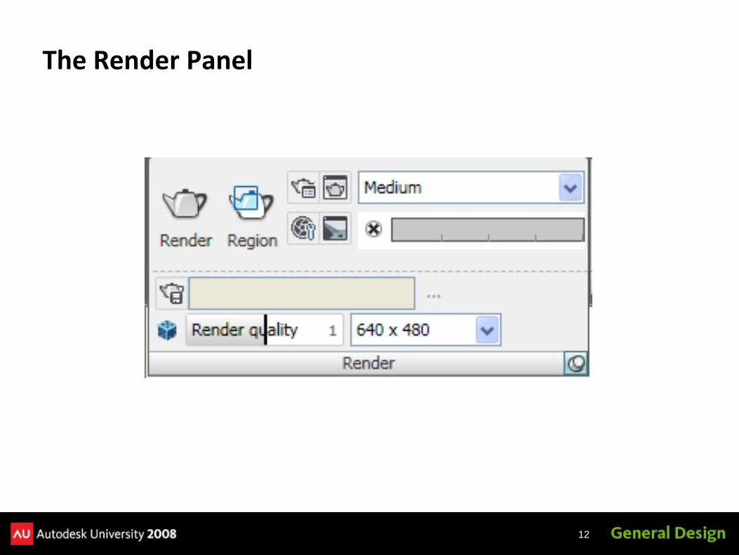
The Render Panel
13
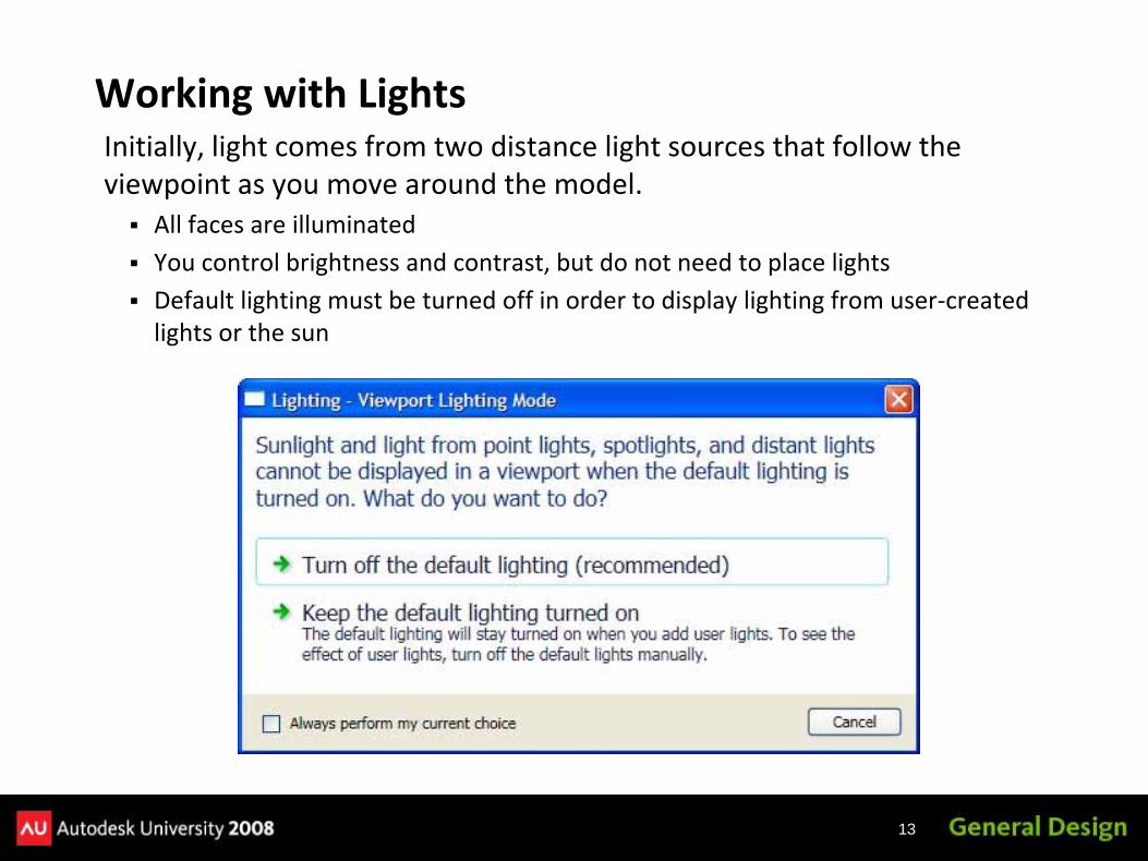
Initially, light comes from two distance light sources that follow the viewpoint as you move around the model.
All faces are illuminatedYou control brightness and contrast, but do not need to place lightsDefault lighting must be turned off in order to display lighting from user‐created lights or the sun
Working with Lights
14
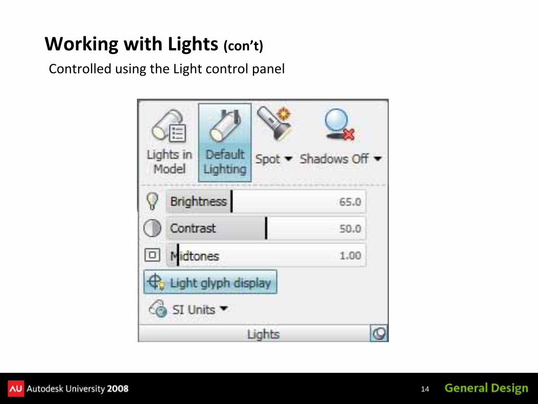
Controlled using the Light control panel
Working with Lights (con’t)
15
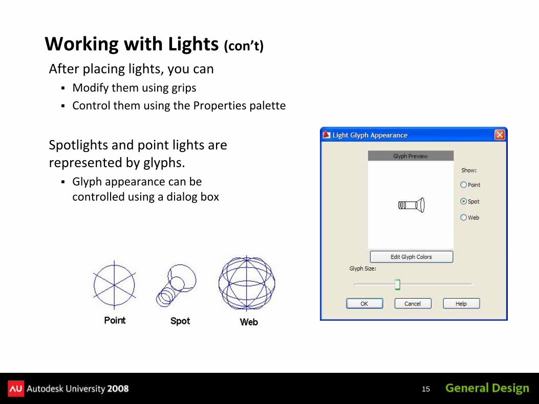
After placing lights, you canModify them using gripsControl them using the Properties palette
Spotlights and point lights are represented by glyphs.
Glyph appearance can be controlled using a dialog box
Working with Lights (con’t)

16
Photometric LightsNew starting in AutoCAD 2008
Use photometric (light energy) valuesMore accurately define lights as they would be in the real worldLamp intensity expressed in Candela, Lumen, or Lux
Controlling via LIGHTINGUNITS system variable
Value Description
0 No lighting units used; standard (generic) lighting is enabled(system used in AutoCAD 2007 and earlier)
1 Photometric lighting enabled using International lighting units
2 Photometric lighting enabled using American lighting units

17
Point Light (a light bulb)Radiates in all directionsIntensity diminishes over distanceIn ACAD2008/2009, can add a target point
Types of Lights

18
Spotlight (a spotlight)Emits a directional cone of lightIntensity diminishes over distanceYou can control the hotspot and falloffIn ACAD2008/2009, can add a FREESPOT (has no target)
Types of Lights (con’t)
19
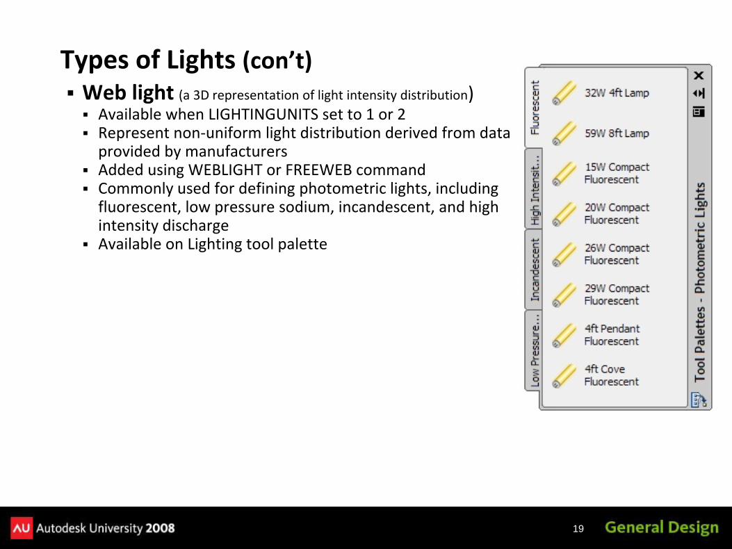
Web light (a 3D representation of light intensity distribution)Available when LIGHTINGUNITS set to 1 or 2Represent non‐uniform light distribution derived from data provided by manufacturersAdded using WEBLIGHT or FREEWEB commandCommonly used for defining photometric lights, including fluorescent, low pressure sodium, incandescent, and high intensity dischargeAvailable on Lighting tool palette
Types of Lights (con’t)
20
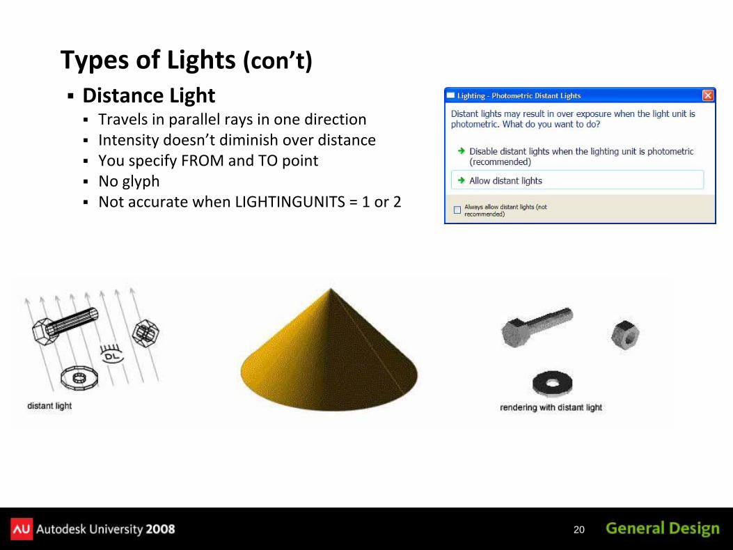
Distance LightTravels in parallel rays in one directionIntensity doesn’t diminish over distanceYou specify FROM and TO pointNo glyphNot accurate when LIGHTINGUNITS = 1 or 2
Types of Lights (con’t)
21
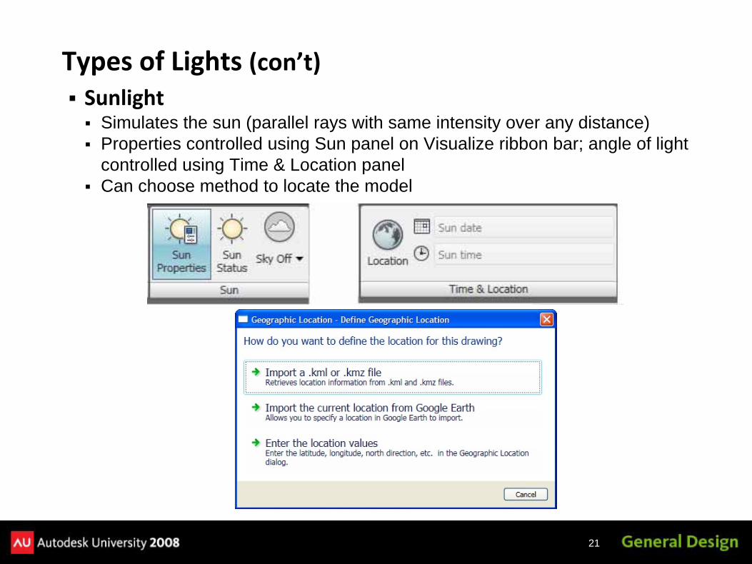
SunlightSimulates the sun (parallel rays with same intensity over any distance)Properties controlled using Sun panel on Visualize ribbon bar; angle of light controlled using Time & Location panelCan choose method to locate the model
Types of Lights (con’t)

22
SunlightDifferent methods to specify locationChange settings using Sun Properties palette
Types of Lights (con’t)

23
Available when using photometric lightsControl sky propertiesGround plane (horizon)HazeScale and appearanceof a sun diskOther sky and backgroundsettings
Sun & Sky Background
24
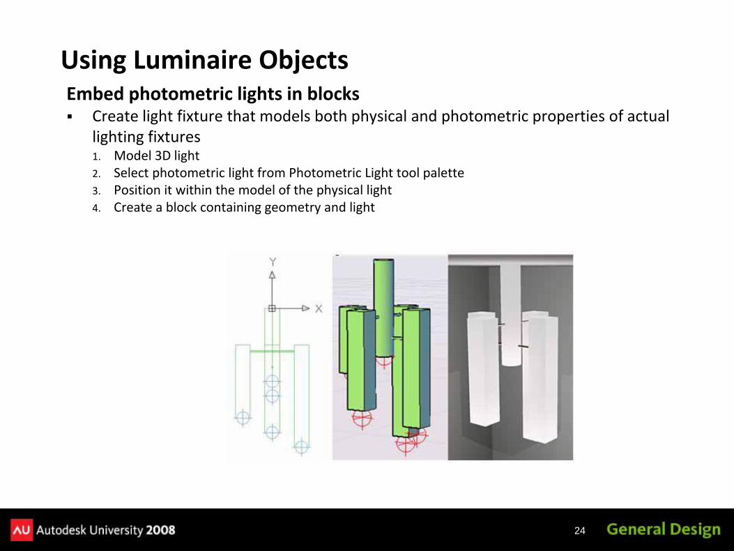
Embed photometric lights in blocksCreate light fixture that models both physical and photometric properties of actual lighting fixtures1. Model 3D light2. Select photometric light from Photometric Light tool palette3. Position it within the model of the physical light4. Create a block containing geometry and light
Using Luminaire Objects

25

26
Each light (except sun & lights in blocks and xrefs) appears in the Lights in Model palette and can be controlled in the Properties palette
TypeStatusShadowsIntensityColorOther settings
attenuationshape
Controlling Lights

27
400+ materialsNeed to install material library (during install or use Add/Remove programs)Available on palettesMaterials in current drawing appear in a Materials window
Working With Materials

28
To an object – drag onto object or use Apply Material to Object buttonTo a face – press Ctrl and drag onto face of objectBy layer – use Attach by Layer button to display dialog box
Applying Materials
29
Realistic & Realistic Metal – based on physical propertiesAdvanced & Advanced Metal – materials with more options
You can create or modify materials in either the Material tool palette or the Materials window:
Changes made in the tool palette affect the materials libraryMake a copy first and then modify the copy
Changes made in the Materials window affect only the drawingYou can add any new materials to the tool palette so that they will be available for use in other drawings
Creating and Modifying Materials

30
Template – specifies type of materialColor – color of materialBy Object – material color based on color of object attached toDiffuse – main color of material (Advanced & Advanced metal templates only)Ambient – color of faces lit by ambient light only (Advanced & Advanced metal templates only)Specular – color of highlight on shiny material (Advanced only)Shininess – reflective quality of materialOpacity – how much light passes through surface (not available for metals)Reflection – how reflective (Advanced & Advanced metal templates only)Refraction index – bending of light rays (1.0 = no distortion; 1.5 = significant distortion (Not available for metal templates)Translucency – percentage of light transmitted through object; 0.0 = not translucent, 100.0 = as translucent as possible (Not available for metal templates)Self‐illumination – material appears to emit light; does not cast light on objects (Not available for metal templates)Luminance – material appears to be lit by photometric light source; no light is cast on other objectsTwo‐sided – both sides of material are rendered in scene
Creating and Modifying Materials (con’t)
31
Texture maps add additional realism to a material by including a 2D image or map projected onto the surface of an object
Diffuse map – assigns a pattern or texture to a material’s diffuse color (or select a procedural map)Reflection map – simulate scene reflected on a shiny surface (512x480 min.)Opacity map – areas of opacity and transparency (white = opaque; black = transparent)Bump map – embossed appearance (dark = no depth; light = projecting)
Using Texture Maps

32
Previous versions of AutoCAD included landscape objects such as trees and people. Those commands are no longer available, but you can achieve similar results by creating new materials using texture maps and opacity maps.
Use old ACAD image filesDiffuse map: shows treeOpacity map: white is solid/black is transparent
Opacity Maps

33
Add realism by generating appearance of material mathematically.Seven types now in AutoCADCheckerMarbleNoiseSpeckleTilesWavesWood
Procedural Maps
34
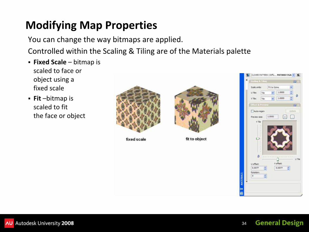
You can change the way bitmaps are applied.Controlled within the Scaling & Tiling are of the Materials paletteFixed Scale – bitmap is scaled to face or object using a fixed scaleFit –bitmap is scaled to fit the face or object
Modifying Map Properties

35
You can create your own bitmaps—scan or digital photo–Save as BMP, GIF, JPEG, PCX, PNG, TGA, or TIF
–Make sure that they tile seamlessly
Preparing Your Own Bitmaps
No longer needed with addition of Mirror mapping

36
Use controls to adjust the scaling and tiling of a materialNone – pattern is not repeatedTile – pattern repeats as a series of tilesMirror – doubles map, flips the doubled copy, and then represents the doubled pattern as a series of tiles
Modifying Map Properties (con’t)

37
After attaching a material with texture, you can adjust the orientation of the texture map, using Mapping tool in Materials panel of the Visualize ribbon bar
Adjusting Material Mapping

38

39
Please remember to fill out your evaluation form
This is session GD111‐3
Evaluation Forms
40
This class will continue withRendering Techniques in 3D AutoCAD, Part 2
GD115‐2Here in this room starting at 3:15
To be continued…

41
The Certification is Free.The Benefit is Invaluable.Free Autodesk Certification during AU
No exam fee (worth up to $125)Get a free, internationally recognized credentialThe offer is valid for six months after AU at participating Authorized Autodesk Training Centers in Canada and the US
What to doWhen you arrived and registered at AU, you received a voucher that waives the exam feeGo to Zeno 4710, present the voucher, take the exam.But don’t delay. Exam space is limited at AU—it’s first come, first served
Certification exams are available for:AutoCAD, AutoCAD Architecture, AutoCAD Civil 3D, Autodesk Inventor and Revit Architecture
Get Certified. Get Ahead.
42
To contact me:
David S. Cohn711 Chuckanut Drive NorthBellingham, WA 98229‐6921
360‐733‐0711mailto:[email protected] (incl. handout online)www.cadman‐do.blogspot.com
Questions & Answers
This concludes the American Institute of Architects Continuing Education Systems Program
43