renewable energy based water pumping system employing...
TRANSCRIPT
SEEE DIGIBOOK ON ENGINEERING & TECHNOLOGY, VOL. 01, MAY 2018 ALTERNATE ENERGY TECHNOLOGIES
978-81-933187-0-6 © 2018 SEEEPEDIA.ORG Society for Engineering Education Enrichment
Rizwan Zaman.H, [email protected] Dr.K.Ranjith Kumar, [email protected]
Renewable Energy based Water Pumping System
Employing Sensorless control of BLDC Motor
RIZWAN ZAMAN.H, Dr.K.RANJITH KUMAR Government college of Technology, Coimbatore, India
[email protected], [email protected]
Abstract—This paper proposes a simple, cost-effective, and efficient renewable energy based water pumping system. A zeta converter is utilized as a DC-DC converter which extracts maximum power coming out from solar PV array. The soft starting of BLDC motor can be achieved by the control of zeta converter by incremental conductance maximum power point tracking (INC-MPPT). Sliding mode controller is employed to provide an accurate maximum power point tracking of photovoltaic systems using single control stage. Sensorless control of BLDC motor is employed for high efficiency and high reliability operation. Adaptive commutation error compensation strategy for the sensor less brushless DC (BLDC) motor is employed based on the flux linkage function. The results of the proposed system through simulation results are shown using MATLAB/Simulink software Index Terms— Brushless dc (BLDC) motor, incremental conductance maximum power point tracking (INC-MPPT), Sliding Mode Controller (SMC), solar photovoltaic (SPV) array, voltage-source inverter (VSI), zeta converter.
I. INTRODUCTION
The reduction in the cost of power electronic devices in near future invites to use the solar photovoltaic generated electrical energy for various applications. The water pumping, a standalone application of the solar photovoltaic array-generated electricity, is receiving wide attention nowadays for irrigation in the fields, household applications, and industrial use. The zeta converter in association with a permanent-magnet brushless dc (BLDC) motor is found to be good technique to develop renewable energy based water pumping system. The zeta converter has been used in some other SPV-based applications [1]–[3]. Moreover, a topology of SPV array-fed BLDC motor-driven water pump with zeta converter has been reported and its significance has been presented more or less in [4]. Nonetheless, an experimental validation is missing and the absence of extensive literature review and comparison with the existing topologies has concealed the technical contribution and originality of the reported work. The advantages of both zeta converter and BLDC motor can contribute to develop a Solar PV array-fed water pumping system possessing a potential of operating satisfactorily under dynamically changing atmospheric conditions. The BLDC motor has high efficiency, high reliability, high inertia/torque ratio, low radio frequency interference and noise, improved cooling, and requires practically very less maintenance [5]. A zeta converter exhibits the following advantages over the conventional buck, boost, buck–boost converters, and Cuk
converter when employed in SPV-based applications. Belonging to a family of buck–boost converters, the zeta converter may be operated either to increase or to decrease the output voltage. Unlike a classical buck-boost converter [10], the zeta converter has a continuous output current. The output inductor makes the current continuous and ripples free.
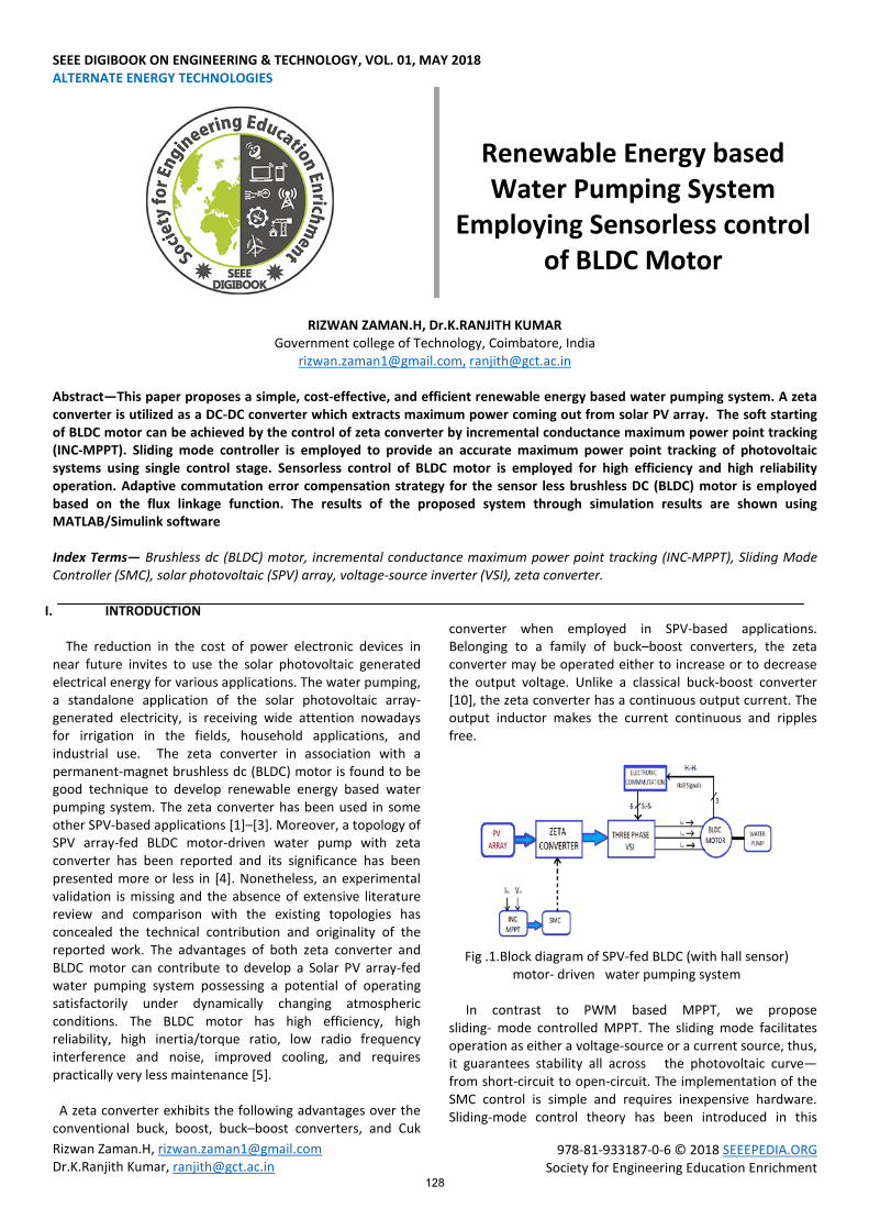
Fig .1.Block diagram of SPV-fed BLDC (with hall sensor)
motor- driven water pumping system In contrast to PWM based MPPT, we propose sliding- mode controlled MPPT. The sliding mode facilitates operation as either a voltage-source or a current source, thus, it guarantees stability all across the photovoltaic curve—from short-circuit to open-circuit. The implementation of the SMC control is simple and requires inexpensive hardware. Sliding-mode control theory has been introduced in this
128

SEEE DIGIBOOK ON ENGINEERING & TECHNOLOGY, VOL. 01, MAY 2018
978-81-933187-0-6 © 2018 SEEEPEDIA.ORG Society for Engineering Education Enrichment
paper. This controller is aimed at performing a fast MPPT action on PV systems using a single control stage. Since this solution is based on a non-linear model, no linearization process is needed. Hence this approach avoids the circular dependency among cascade controllers, reduces the number of control devices and provides global stability in all the operation range. These characteristics are major improvements over classical maximum power point tracking solutions based on linear and cascade controllers. The SMC provides a much faster tracking of the MPP, it increasing the produced energy. Therefore, the proposed SMC enables to increment the profitability of PV installations, and hence the return-of-investment time is reduced. Finally, a further improvement to the sliding mode controller could be performed in a future work to improve the performance of the SMC operation. This fresh development will enable to constraint the hysteresis band of the sliding mode controller, which will eventually enable to reduce the settling time of the PV power to achieve a faster MPPT procedure.
Fig.2. Block diagram of the SMC and PV system An incremental conductance maximum power point tracking (INC-MPPT) algorithm is used to operate the zeta converter such that the SPV array always operates at its maximum power point (MPP). II.CONFIGURATION OF PROPOSED SYSTEM The structure of proposed renewable energy based water pumping system employing a zeta converter is shown in Figure 1. The proposed system consists of (left to right) a Solar PV array, a zeta converter, a VSI, a BLDC motor and a water pump. Sensorless control of BLDC motor, INC-MPPT and SMC controller are employed. Sensorless BLDC motor control block diagram is shown in figure 3. III.OPERATION OF PROPOSED SYSTEM The SPV array generates the electrical power demanded by motor-pump. This electrical power is fed to the motor-pump
via a zeta converter and a VSI. The SPV array appears as a power source for the zeta converter as shown in Figure 1. In ideal case the zeta converter output is same as the output coming out from solar PV array which appears as an input source for the VSI. In practice, due to the various losses associated with a DC-DC converter, slightly less amount of power is transferred to feed the VSI. The INC-MPPT algorithm uses voltage and current as feedback from solar PV array and generates an optimum value of duty cycle. Further, it generates actual switching pulse by comparing the duty cycle with a high frequency carrier wave. In this way, the maximum power extraction and hence the efficiency optimization of SPV array is accomplished. Sliding mode controller is employed to track the maximum power point fast and accurate. The VSI, converting DC output from a zeta converter into AC, feeds the BLDC motor to drive a water pump coupled to its shaft. An adaptive commutation error compensation strategy for the sensorless brushless DC (BLDC) motor based on the flux linkage function. The efficiency of the proposed system is improved and high frequency switching losses are eliminated. Brushless motors are more efficient as its velocity is determined by the frequency at which current is supplied, not the voltage. As brushes are absent, the mechanical energy loss due to friction is less which enhanced efficiency. BLDC motor can operate at high-speed under any condition.
Fig.3.Sensorless BLDC motor control block diagram
A. Design of Zeta Converter: The zeta converter design consists of an estimation of various components such as input inductor L1, output inductor L2 and intermediate capacitor C1. These components are designed such that the zeta converter always operates in CCM resulting in reduced stress on its components and devices. An estimation of the duty cycle, D initiates the design of zeta converter which is estimated as [6], 𝐷 = Vdc
Vdc+𝑉𝑚𝑝𝑝 (1)
129
SEEE DIGIBOOK ON ENGINEERING & TECHNOLOGY, VOL. 01, MAY 2018
978-81-933187-0-6 © 2018 SEEEPEDIA.ORG Society for Engineering Education Enrichment
Where, Vdc is an average value of output voltage of the Zeta converter (DC link voltage of VSI) equal to DC voltage rating of BLDC motor. Average current flowing through the dc link of VSI is given by 𝐼𝑑𝑐 = Pmpp
Vdc (2)
L1, L2 and C1 are estimated as [6], 𝐿1 = 𝐷 ∗ 𝑉𝑚𝑝𝑝
𝑓𝑠𝑤∗∆𝐼𝐿1 (3)
𝐿2 = (1 − 𝐷) ∗ 𝑉𝑑𝑐
𝑓𝑠𝑤∗∆𝐼𝐿2 (4)
𝐶1 = 𝐷∗𝑉𝑑𝑐
𝑓𝑠𝑤∗∆𝑉𝐶1 (5)
Where fsw is the switching frequency of IGBT switch of zeta converter, ∆𝐼𝐿1 is the amount of permitted ripple in the current flowing through L1 ,same as 𝐼𝐿1=Impp, , ∆𝐼𝐿2 is the amount of permitted ripple in the current flowing through L2,same 𝐼𝐿2=Idc, , ∆𝑉𝐶1 is the amount of permitted ripple in the voltage across C1,same as 𝑉𝐶1= 𝑉𝑑𝑐. B. Design of solar PV The practical converters associated with various power losses and the performance of BLDC motor pump is influenced by associated mechanical and electrical losses. To compensate these losses, the size of solar PV array is selected with slightly more peak power capacity to ensure the satisfactory operation regardless of power losses. Under STC (1000 W/m², 25°C)
𝑃𝑚𝑝𝑝 = 3266 𝑊
𝑉𝑚𝑝𝑝 = 185.4 𝑉 The current of solar PV array at MPP, 𝐼𝑚𝑝𝑝 = 𝑃𝑚𝑝𝑝
𝑉𝑚𝑝𝑝= 3266
185.4= 17.61 𝐴 (6)
Number of modules required to connect in series are as, 𝑁𝑠 = 𝑉𝑚𝑝𝑝
𝑉𝑚= 185.4
30.9= 6 (7)
Number of modules required to connect in parallel are as, 𝑁𝑝 = 𝐼𝑚𝑝𝑝
𝐼𝑚= 17.61
8.81= 2 (8)
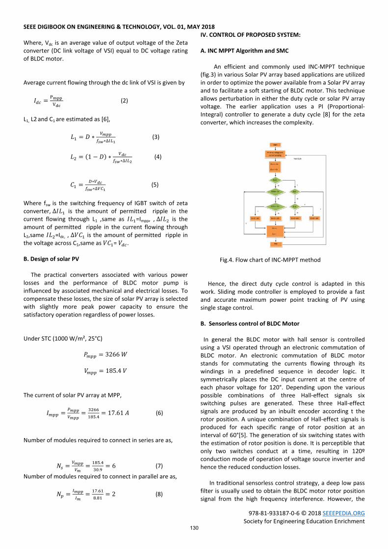
IV. CONTROL OF PROPOSED SYSTEM: A. INC MPPT Algorithm and SMC An efficient and commonly used INC-MPPT technique (fig.3) in various Solar PV array based applications are utilized in order to optimize the power available from a Solar PV array and to facilitate a soft starting of BLDC motor. This technique allows perturbation in either the duty cycle or solar PV array voltage. The earlier application uses a PI (Proportional-Integral) controller to generate a duty cycle [8] for the zeta converter, which increases the complexity.
Fig.4. Flow chart of INC-MPPT method Hence, the direct duty cycle control is adapted in this work. Sliding mode controller is employed to provide a fast and accurate maximum power point tracking of PV using single stage control. B. Sensorless control of BLDC Motor In general the BLDC motor with hall sensor is controlled using a VSI operated through an electronic commutation of BLDC motor. An electronic commutation of BLDC motor stands for commutating the currents flowing through its windings in a predefined sequence in decoder logic. It symmetrically places the DC input current at the centre of each phasor voltage for 120°. Depending upon the various possible combinations of three Hall-effect signals six switching pulses are generated. These three Hall-effect signals are produced by an inbuilt encoder according t the rotor position. A unique combination of Hall-effect signals is produced for each specific range of rotor position at an interval of 60°[5]. The generation of six switching states with the estimation of rotor position is done. It is perceptible that only two switches conduct at a time, resulting in 120º conduction mode of operation of voltage source inverter and hence the reduced conduction losses. In traditional sensorless control strategy, a deep low pass filter is usually used to obtain the BLDC motor rotor position signal from the high frequency interference. However, the
130

SEEE DIGIBOOK ON ENGINEERING & TECHNOLOGY, VOL. 01, MAY 2018
978-81-933187-0-6 © 2018 SEEEPEDIA.ORG Society for Engineering Education Enrichment
delayed angle caused by the low pass filter may be more than 90 electrical degrees in the high speed range. Therefore, a novel sensorless control strategy based on the speed–independent flux linkage function is proposed in this paper. V. RESULTS AND DISCUSSION A. Zeta Converter output Results Table I shows the zeta converter output parameters for different irradiance level i.e. (1000 W/m² and 800/m²) and the output power variation with SMC and without SMC is discussed. Table I: Zeta converter output parameter values for different irradiance level where Vdc is the zeta converter output voltage in volts Idc is the zeta converter output current in Amps PMPP is the power at maximum power point in watts
Vdc (v) vs Time(s)
Fig.5.Zeta converter output voltage for 1000 W/m2 irradiance level (without SMC) Vdc (v) vs Time(s)
Fig.6.Zeta converter output voltage for 800 W/m2 irradiance level (without SMC) Vdc (v) vs Time(s)
Fig.7. Zeta converter output voltage for 1000 W/m2 irradiance level (with SMC) Vdc (v) vs Time(s)
Fig.8. Zeta converter output voltage for 800 W/m2 irradiance level (with SMC) Figure 5 and 6 shows the output voltage of the zeta converter with SMC at different irradiance levels 1000 W/m2 and 800 W/m2.
Figure 7 and 8 shows the output voltage of the zeta converter without SMC at different irradiance levels 1000 W/m2 and 800 W/m2. Motor specification
Stator phase/phase resistance, Rs = 0.36 Ω;
Stator phase/phase inductance, Ls= 1.3 mH;
Torque constant, Kt = 0.49 Nm/Apeak;
Voltage constant, Ke = 51 Vpeak L-L/krpm;
Rated current, IS rated = 18.9 A;
Rated torque, T rated = 9.2 Nm;
Rated speed, N rated = 3000 rpm ;
No. of poles, P = 6;
Moment of inertia, J = 17.5 kg.cm2;
Proportionality constant, K = 9.32*10-5.
PARAMETERS
WITHOUT SMC WITH SMC IRRADIANCE
(W/m2) IRRADIANCE
(W/m2) 1000 800 1000 800
Vdc (V) 172.2 171.6 175.6 174.3 Idc (A) 15.9 14.1 16.8 14.8
PMPP (W) 2742 2418 2955 2581
131

SEEE DIGIBOOK ON ENGINEERING & TECHNOLOGY, VOL. 01, MAY 2018
978-81-933187-0-6 © 2018 SEEEPEDIA.ORG Society for Engineering Education Enrichment
B. Solar PV characteristics plot
Fig.9.Solar photovoltaic PV and IV characteristics Figure 9 shows the solar photovoltaic PV and IV characteristics of the proposed system. C. Simulation Results for BLDC motor pump
Fig.10. BLDC motor output waveform of Stator current (ia) and back emf (ea)
Te(Nm) vs Time(s)
Fig.11.BLDC motor output waveform of electro-magnetic torque (Nm) Rotor speed N (rpm) vs Time(s)
Fig.12. BLDC motor output waveform of speed N(rpm) VI. CONCLUSION The Renewable energy based water pumping system has been proposed and results are simulated using MATLAB software. The combination of zeta converter and BLDC motor has improved the performance of Solar PV array based water pumping system. The output voltage, current and power of zeta converter at different solar irradiance level has been compared with and without sliding mode controller (SMC). The MPP extraction of the Solar PV array has been achieved by the implementation of INC-MPPT algorithm and SMC. Sensorless control of BLDC motor is employed for high efficiency and high reliability operation. The performance characteristics of BLDC motor pump are simulated using MATLAB/Simulink software.
ACKNOWLEDGEMENT
The authors are thankful to the authorities of Government college of Technology, Coimbatore for the facilities rendered to carry out this research work
REFERENCES [1] R. Arulmurugan and N. Suthanthiravanitha, March
2015“Model and Design of A Fuzzy-Based Hopfield NN Tracking Controller for Standalone PV Applications,” Electr. Power Syst. Res., vol. 120, pp.184-193, March 2015.
[2] S. Satapathy, K.M. Dash and B.C. Babu, April 2013“Variable Step Size MPPT Algorithm for Photo Voltaic Array Using Zeta Converter - A Comparative
132
SEEE DIGIBOOK ON ENGINEERING & TECHNOLOGY, VOL. 01, MAY 2018
978-81-933187-0-6 © 2018 SEEEPEDIA.ORG Society for Engineering Education Enrichment
Analysis,” Students Conference on Engineering and Systems (SCES).
[3] M.Uno and A.Kukita, “Single-Switch Voltage Equalizer Using Multi- Stacked Buck-Boost Converters for Partially-Shaded Photovoltaic Modules,” IEEE Trans. Power Electron., vol.30, no.6, pp.3091-3105, June 2015.
[4] Nagaraj, B., and P. Vijayakumar. "Soft Computing Based PID Controller Tuning and Application to the Pulp and Paper Industry." Sensors & Transducers 133.10 (2011): 30.
[5] B. Singh, V. Bist, A. Chandra and K. Al-Haddad, April 2015“Power Factor Correction in Bridgeless-Luo Converter-Fed BLDC Motor Drive,” IEEE Trans. Ind. Appl., vol.51, no.2, pp.1179-1188.
[6] Rajan Kumar and Bhim Singh,Dec 2014, “BLDC Motor Driven Solar PV Array Fed Water Pumping System Employing Zeta Converter,” in 6th IEEE India International Conference on Power Electronics (IICPE).
[7] B. Singh and V. Bist,May 2015 “Power quality improvements in a zeta converter for brushless DC motor drives,” IET Science, Measurement & Technology, vol.9, no.3, pp.351-361.
[8] Nagaraj, B., P. Muthusami, and N. Murugananth. "Optimum PID Controller Tuning Using Soft computing Methodologies for Industrial Process." Karpagam Journal of Computer Science: 1761.
[9] R.F. Coelho, W.M. dos Santos and D.C. Martins,Nov 2012 “Influence of Power Converters on PV Maximum Power Point Tracking Efficiency,” 10th IEEE/IAS International Conference on Industry Applications (INDUSCON).
[10] M. Sitbon, S. Schacham and A. Kuperman, September 2015“Disturbance Observer- Based Voltage Regulation of Current-Mode-Boost-Converter Interfaced PV Generator,” IEEE Trans. Ind. Electron., vol.62, no.9, pp.5776-5785.
[11] M.A. Elgendy, B. Zahawi and D.J. Atkinson,Jan 2013 “Assessment of the Incremental Conductance Maximum Power Point Tracking Algorithm,” IEEE Trans. Sustain. Energy, vol.4, no.1, pp.108-117.
[12] Rajan Kumar and Bhim Singh,Dec 2014, “Buck-boost converter fed BLDC motor drive for solar PV array based water pumping,” IEEE International Conference on Power Electronics, Drives and Energy Systems (PEDES).
[13] P. Pillay, R. Krishnan; “Modeling, simulation, and analysis of permanent-magnet motor drives. II: The Brushless DC Motor Drive”, IEEE Trans. Ind. Appl., vol. 25, no. 2, pp. 274-279, Mar/Apr 1989
[14] H. Li, S. Zheng and H. Ren, "Self-Correction of Commutation Point for High-Speed Sensorless BLDC Motor With Low Inductance and Nonideal Back EMF," in IEEE Transactions on Power Electronics, vol. 32, no. 1, pp. 642-651, Jan. 2017
[15] Nagaraj, B., and P. Vijayakumar. "CONTROLLER TUNING FOR INDUSTRIAL PROCESS-A SOFT COMPUTING APPROACH." Int. J. Advance. Soft Comput. Appl 4.2 (2012).
[16] Ghazanfari, J.; Farsangi, M.M.,2013,” Maximum Power Point using Sliding Mode Control for Photovoltaic Array”. Iran. J. Electr. Electron. Eng. 189–19619.
[17] Khemiri, N.; Khedher, A.; Mimouni, M.F.,March 2013, “A sliding mode control approach applied to a photovoltaic system operated in MPPT”. In Proceedings of Systems, Signals & Devices (SSD), 2013 10th International Multi-Conference, Hammamet, Tunisia, pp. 1–6.
[18] Kish, G.J.; Lee, J.J.; Lehn, P.W. 2012,”Modelling and control of photovoltaic panels utilising the incremental conductance method for maximum power point tracking”. IET Renew. Power Gener,259–266
[19] Afghoul,H.;Chikouche,D.;Krim,F.;Beddar,A.Anovel, 2013,” Implementation of MPPT sliding mode controller for PV generation systems”. In Proceedings of EUROCON, 2013 IEEE, Zagreb, Croatia, pp. 789–794.
133