renewable energy-based water supply systems - solar powernew... · renewable energy-based water...
TRANSCRIPT
GRUNDFOS DATA BOOKLET
Grundfos solar surface pumpRenewable energy-based water supply systems
Ta
ble
of c
on
ten
ts
2
Grundfos solar surface pump
1. MGFlex motor 3Features and benefits 3Nameplate 3Connection terminals (FM 300) 4Wiring connections 6Technical data 7Motor range 8
2. System components 9IO 50 switch box 9IO 101 switch box 9Generator 9
3. CRFlex pump 10Pumped liquids 10Nameplate 10System sizing 10Material specification 11Product range 12
4. Applications 13CRFlex Solar 13CRFlex Solar with level switch 14CRFlex Solar with generator 15CRFlex Solar with level switch and generator 16CRFlex and SQFlex Solar 17
5. Accessories 18
6. Technical data 19Dimensions and weights 19Electrical data 21
7. Performance curves 22Curve conditions 22CRFlex 1-9 23CRFlex 1-17 24CRFlex 3-5 25CRFlex 3-11 26CRFlex 5-2 27CRFlex 5-6 28CRFlex 10-1 29CRFlex 10-2 30CRFlex 15-1 31
8. Appendix 32Performance curves, CRI, CRN 1 32Performance curves, CRI, CRN 3 33Performance curves, CRI, CRN 5 34Performance curves, CRI, CRN 10 35Performance curves, CRI, CRN 15 36
9. Further product documentation 37WebCAPS 37WinCAPS 38
MG
Fle
x m
oto
r
Grundfos solar surface pump 1
1. MGFlex motor
The MGFlex motor is a permanent magnet motor. Motor comes with two different sizes: frame size 80/90 and with integrated frequency converter.
The frequency converter enables the motor to run at high efficiency in a wide speed range:
• power input (P1) of 40 to 880 W and 60 to 1730 W
• motor speed of 1000 to 3600 min-1
• maximum input current of 4.6 A and 8.9 A
• enclosure class IP55.
The motor is suitable for both DC and AC voltage supply:
• 30-300 VDC, PE
• 1 x 90-240 VAC, - 10 %/+ 6 %, 50/60 Hz, PE.
The MGFlex motor can be mounted on Grundfos CR and MTR (as float pump) pumps.
Features and benefits
Maximum Power Point Tracking (MPPT)
The motor continuously optimises the speed according to the input power available when connected to DC supply.
Wide voltage range
The wide voltage range enables the motor to operate at any voltage from 30 to 300 VDC or 90 to 240 VAC.
Overvoltage and undervoltage protection
Overvoltage and undervoltage may occur in case of unstable power supply or a faulty installation. The motor will be stopped if the voltage falls outside the permissible voltage range, and it will be restarted when the voltage is again within the permissible voltage range. Therefore, no additional protection relay is required.
Overload protection
The motor incorporates thermal protection against both steady overload and stalled condition according to IEC 60034-11. It will be stopped and restarted automatically.
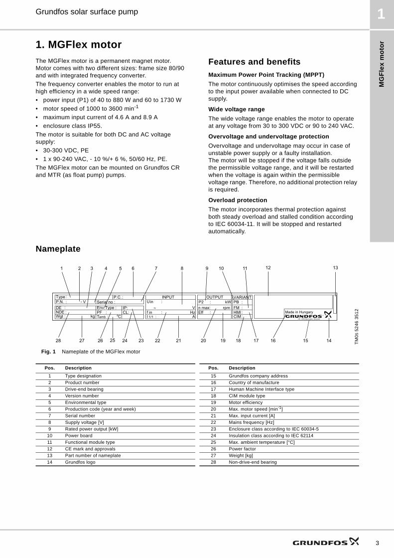
Nameplate
Fig. 1 Nameplate of the MGFlex motorT
M0
5 5
24
6 3
51
2Env.Type : Serial no :
IP:CL:PF
PBFMHMIEff
n max:
CIMWgt :
DE :
kgNDE :
Tamb ::
C A
V~
P.C. :
Made in Hungary
OUTPUT VARIANTINPUTType :P.N. : U in :
I 1/1 :f in
kW
Hz
P2rpm
: : ::
::
:
o
1 2
24
3 4 5 6
2728 26 25 23 22
7 8 9 10 11
15 14
12 13
161718192021
DK - 8850 Bjerringbro, Denmark
- V
Pos. Description Pos. Description
1 Type designation 15 Grundfos company address
2 Product number 16 Country of manufacture
3 Drive-end bearing 17 Human Machine Interface type
4 Version number 18 CIM module type
5 Environmental type 19 Motor efficiency
6 Production code (year and week) 20 Max. motor speed [min-1]
7 Serial number 21 Max. input current [A]
8 Supply voltage [V] 22 Mains frequency [Hz]
9 Rated power output [kW] 23 Enclosure class according to IEC 60034-5
10 Power board 24 Insulation class according to IEC 62114
11 Functional module type 25 Max. ambient temperature [°C]
12 CE mark and approvals 26 Power factor
13 Part number of nameplate 27 Weight [kg]
14 Grundfos logo 28 Non-drive-end bearing
3

MG
Fle
x m
oto
r
4
Grundfos solar surface pump1
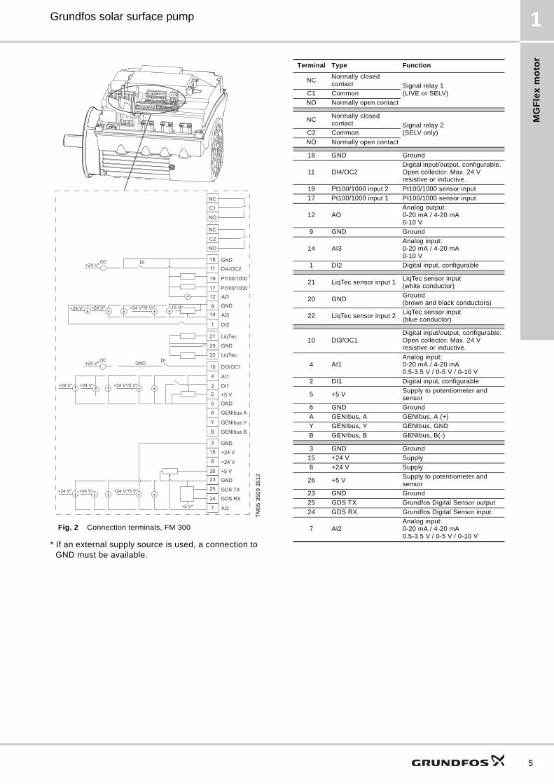
Connection terminals (FM 300)The MGFlex motor with advanced functional module (FM 300) has a number of inputs and outputs enabling the motor to be used in advanced applications where many inputs and outputs are required.
The FM 300 has these connections:
• three analog inputs
• one analog output
• two dedicated digital inputs
• two configurable digital inputs or open-collector outputs
• Grundfos Digital Sensor input and output
• two Pt100/1000 inputs
• LiqTec sensor inputs
• two signal relay outputs
• GENIbus connection.
See fig. 2 in page 5.
Note: Digital input 1 is factory-set to be start/stop input where open circuit will result in stop. A jumper has been factory-fitted between terminals 2 and 6. Remove the jumper if digital input 1 is to be used as external start/stop or any other external function.
Note: As a precaution, the wires to be connected to the connection groups below must be separated from each other by reinforced insulation in their entire lengths.
• Inputs and outputsAll inputs and outputs are internally separated from the mains-conducting parts by reinforced insulation and galvanically separated from other circuits.All control terminals are supplied by safety extra-low voltage (SELV), thus ensuring protection against electric shock.
• Signal relay outputs
– Signal relay 1:LIVE1):Mains supply voltages up to 250 VAC can be connected to this output.SELV:The output is galvanically separated from other circuits. Therefore, the supply voltage or safety extra-low voltage can be connected to the output as desired.
– Signal relay 2:SELV:The output is galvanically separated from other circuits. Therefore, the supply voltage or safety extra-low voltage can be connected to the output as desired.
• Mains supply (terminals N, PE, L or L1, L2, L3, PE).
A galvanically safe separation must fulfil the requirements for reinforced insulation including creepage distances and clearances specified in EN 61800-5-1.1) LIVE: Low voltage with the risk of electric shock if the terminals are
touched.
MG
Fle
x m
oto
r
Grundfos solar surface pump 1
Fig. 2 Connection terminals, FM 300
* If an external supply source is used, a connection to GND must be available.
TM
05
35
09
35
12
3
15
8
2623
25
24
7
21
20
22
B
Y
6
52
4
10
A
+24 V*
1
149
1217
19
11
18
+24 V* +
+24 V*OC DI
+24 V*/5 V*+24 V* +
+ ++24 V*/5 V*+24 V*
+24 V* + ++24 V*/5 V*+24 V*
+5 V* AI2
GDS RX
GDS TX
GND
GENIbus A
GENIbus B
+5 V
+24 V
+24 V
GND
GENIbus Y
GND
+5 VDI1
AI1
DI3/OC1
LiqTec
AI3
GND
DI2
LiqTec
GND
AOPt100/1000
Pt100/1000
DI4/OC2
GND
+24 V*OC DIGND
NC
C2
NO
NC
C1
NO
+5 V*
Terminal Type Function
NCNormally closed contact Signal relay 1
(LIVE or SELV)C1 Common
NO Normally open contact
NCNormally closed contact Signal relay 2
(SELV only)C2 Common
NO Normally open contact
18 GND Ground
11 DI4/OC2Digital input/output, configurable. Open collector: Max. 24 V resistive or inductive.
19 Pt100/1000 input 2 Pt100/1000 sensor input
17 Pt100/1000 input 1 Pt100/1000 sensor input
12 AOAnalog output:0-20 mA / 4-20 mA0-10 V
9 GND Ground
14 AI3Analog input:0-20 mA / 4-20 mA0-10 V
1 DI2 Digital input, configurable
21 LiqTec sensor input 1LiqTec sensor input(white conductor)
20 GNDGround(brown and black conductors)
22 LiqTec sensor input 2LiqTec sensor input(blue conductor)
10 DI3/OC1Digital input/output, configurable.Open collector: Max. 24 V resistive or inductive.
4 AI1Analog input:0-20 mA / 4-20 mA0.5-3.5 V / 0-5 V / 0-10 V
2 DI1 Digital input, configurable
5 +5 VSupply to potentiometer and sensor
6 GND Ground
A GENIbus, A GENIbus, A (+)
Y GENIbus, Y GENIbus, GND
B GENIbus, B GENIbus, B(-)
3 GND Ground
15 +24 V Supply
8 +24 V Supply
26 +5 VSupply to potentiometer and sensor
23 GND Ground
25 GDS TX Grundfos Digital Sensor output
24 GDS RX Grundfos Digital Sensor input
7 AI2Analog input:0-20 mA / 4-20 mA0.5-3.5 V / 0-5 V / 0-10 V
5
MG
Fle
x m
oto
r
6
Grundfos solar surface pump1
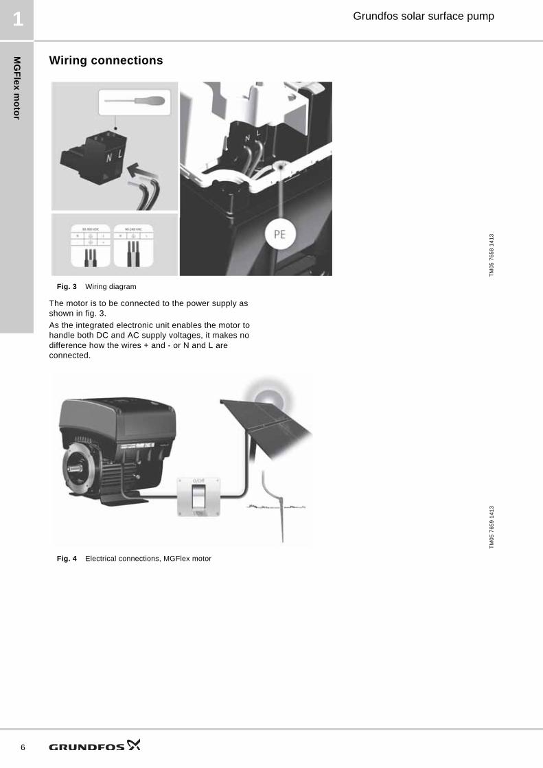
Wiring connections
Fig. 3 Wiring diagram
The motor is to be connected to the power supply as shown in fig. 3.
As the integrated electronic unit enables the motor to handle both DC and AC supply voltages, it makes no difference how the wires + and - or N and L are connected.
Fig. 4 Electrical connections, MGFlex motor
TM
05
76
58
14
13
TM
05
76
59
14
13
MG
Fle
x m
oto
r
Grundfos solar surface pump 1
Technical data
Dimensions
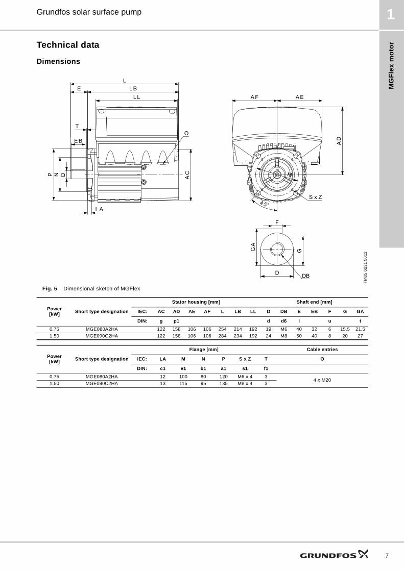
Fig. 5 Dimensional sketch of MGFlex
TM
05
62
31
50
12
Power[kW]
Short type designation
Stator housing [mm] Shaft end [mm]
IEC: AC AD AE AF L LB LL D DB E EB F G GA
DIN: g p1 d d6 I u t
0.75 MGE080A2HA 122 158 106 106 254 214 192 19 M6 40 32 6 15.5 21.5
1.50 MGE090C2HA 122 158 106 106 284 234 192 24 M8 50 40 8 20 27
Power[kW]
Short type designation
Flange [mm] Cable entries
IEC: LA M N P S x Z T O
DIN: c1 e1 b1 a1 s1 f1
0.75 MGE080A2HA 12 100 80 120 M6 x 4 34 x M20
1.50 MGE090C2HA 13 115 95 135 M8 x 4 3
7
MG
Fle
x m
oto
r
8
Grundfos solar surface pump1
Electrical data
Motor range
Note
Grundfos only guarantees the performance and reliability of the MGFlex motors if both conditions below are fulfilled:
1. The motor must be connected to the pump end as described in this document.
2. The assembly of the motor and the pump must be carried out by persons trained and authorised by Grundfos.
In the case of OEM usage, please contact Grundfos to obtain full warranty coverage.
Power supply to pump30-300 VDC, PE.1 x 90 - 240 V, - 10 %/+ 6 %, 50/60 Hz, PE.
Energy sourceSolar module.Generator.Grid.
Start/stop control Digital input for start/stop of motor.
Power switch on/off or DC to/from AC Max. four times per hour.
Enclosure class IP55.
Motor protection
Built-in motor protection:• overvoltage and undervoltage• overload• overtemperature.
Sound pressure level < 42 db (A) for 0.75 kW motor.
Power factor 0.97.
Earth-leakage circuit breakerIf the pump/motor is connected to an earth-leakage circuit breaker (ELCB) for additional protection, this circuit breaker must trip when AC fault currents, pulsating DC or smooth DC fault currents occur.
Ambient temperatureDuring operation: -20 °C to +50 °C.During storage/transport: -25 °C to +70 °C.
Relative humidity Maximum 95 %.
Leaking current< 3.5 mA for AC.< 10 mA for DC.
Installation outdoor The motor/pump must be protected from rain and direct sunlight.
Marking CE.
Insulation class F (IEC 85).
EMC compatibility EN 61800-3.
Product Power P1 [W] Product number
MGFlex 80A 880 98367492
MGFlex 90Sc 1730 98190192
Sy
ste
m c
om
po
ne
nts
Grundfos solar surface pump 2
2. System components
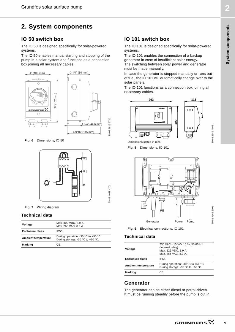
IO 50 switch boxThe IO 50 is designed specifically for solar-powered systems.
The IO 50 enables manual starting and stopping of the pump in a solar system and functions as a connection box joining all necessary cables.
Fig. 6 Dimensions, IO 50
Fig. 7 Wiring diagram
Technical data
IO 101 switch boxThe IO 101 is designed specifically for solar-powered systems.
The IO 101 enables the connection of a backup generator in case of insufficient solar energy. The switching between solar power and generator must be made manually.
In case the generator is stopped manually or runs out of fuel, the IO 101 will automatically change over to the solar panels.
The IO 101 functions as a connection box joining all necessary cables.
Fig. 8 Dimensions, IO 101
Fig. 9 Electrical connections, IO 101
Technical data
GeneratorThe generator can be either diesel or petrol-driven.It must be running steadily before the pump is cut in.
TM
05
58
16
27
12
TM
02
40
58
47
01
VoltageMax. 300 VDC, 8.9 A.Max. 265 VAC, 8.9 A.
Enclosure class IP55.
Ambient temperatureDuring operation: -30 °C to +50 °C.During storage: -30 °C to +60 °C.
Marking CE.
4” (100 mm)
6” (1
52 m
m)
3 1/4” (80 mm)
4 9/16” (115 mm)
1 3/4” (44.6 mm)
TM
02
25
46
40
03
TM
02
41
62
50
01
Voltage
230 VAC - 15 %/+ 10 %, 50/60 Hz (internal relay).Max. 225 VDC, 8.9 A.Max. 265 VAC, 8.9 A.
Enclosure class IP55.
Ambient temperatureDuring operation: -30 °C to +50 °C.During storage: -30 °C to +60 °C.
Marking CE.
199
263 113
Dimensions stated in mm.
PE
Generator Power Pump
9
CR
Fle
x p
um
p
10
Grundfos solar surface pump3
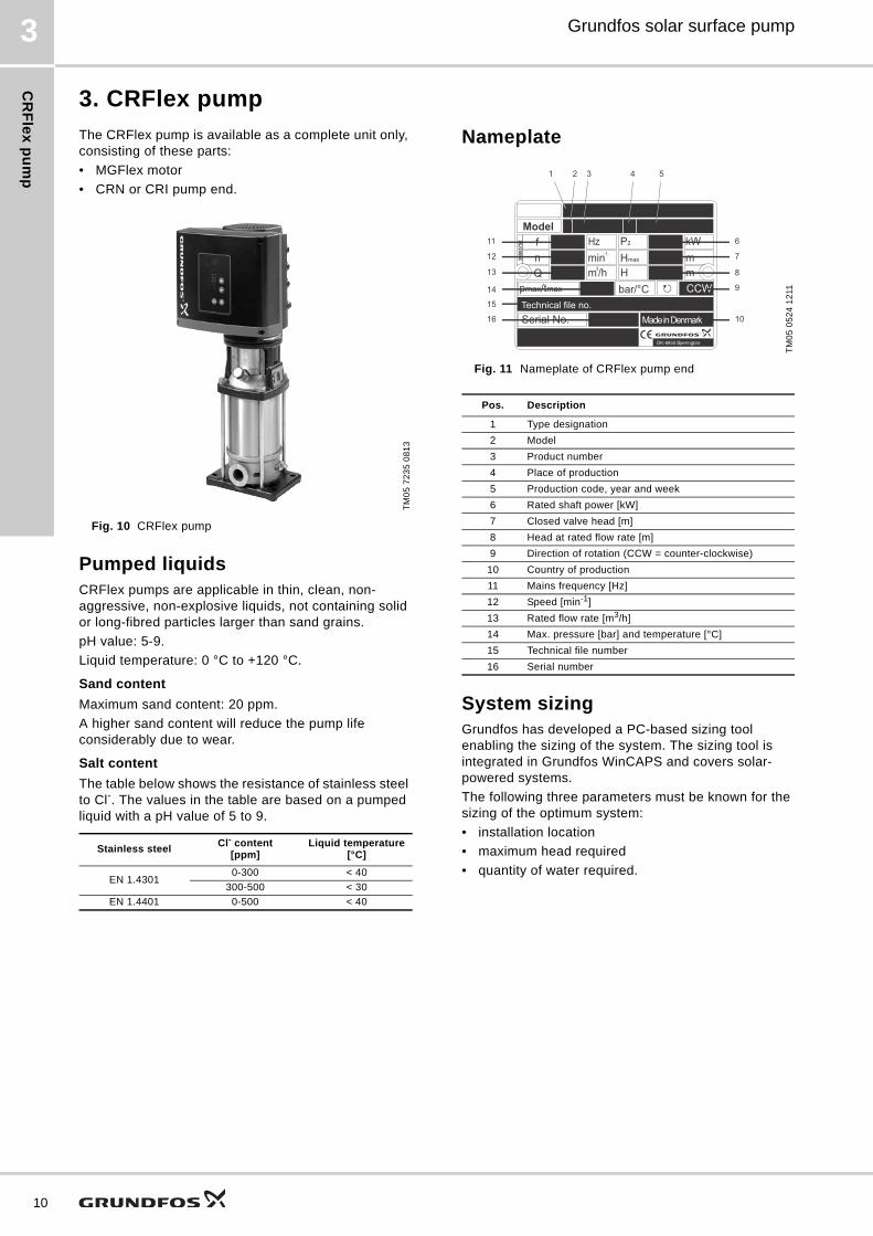
3. CRFlex pump
The CRFlex pump is available as a complete unit only, consisting of these parts:
• MGFlex motor
• CRN or CRI pump end.
Fig. 10 CRFlex pump
Pumped liquidsCRFlex pumps are applicable in thin, clean, non-aggressive, non-explosive liquids, not containing solid or long-fibred particles larger than sand grains.
pH value: 5-9.
Liquid temperature: 0 °C to +120 °C.
Sand content
Maximum sand content: 20 ppm.
A higher sand content will reduce the pump life considerably due to wear.
Salt content
The table below shows the resistance of stainless steel to Cl-. The values in the table are based on a pumped liquid with a pH value of 5 to 9.
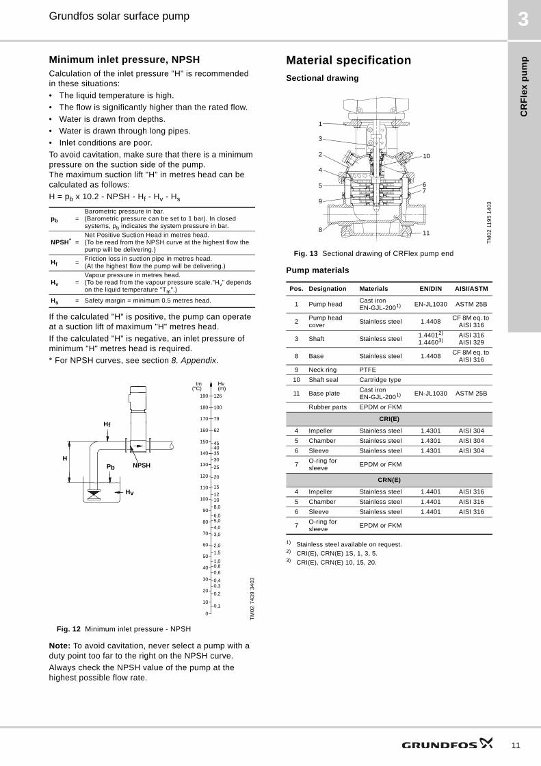
Nameplate
Fig. 11 Nameplate of CRFlex pump end
System sizingGrundfos has developed a PC-based sizing tool enabling the sizing of the system. The sizing tool is integrated in Grundfos WinCAPS and covers solar-powered systems.
The following three parameters must be known for the sizing of the optimum system:
• installation location
• maximum head required
• quantity of water required.
TM
05
72
35
08
13
Stainless steelCl- content
[ppm]Liquid temperature
[°C]
EN 1.43010-300 < 40
300-500 < 30
EN 1.4401 0-500 < 40
TM
05
05
24
12
11
Pos. Description
1 Type designation
2 Model
3 Product number
4 Place of production
5 Production code, year and week
6 Rated shaft power [kW]
7 Closed valve head [m]
8 Head at rated flow rate [m]
9 Direction of rotation (CCW = counter-clockwise)
10 Country of production
11 Mains frequency [Hz]
12 Speed [min-1]
13 Rated flow rate [m3/h]
14 Max. pressure [bar] and temperature [°C]
15 Technical file number
16 Serial number
Model
96505758 f
nQ
Hzmin-1
m3/h
P2
Hmax
H
kWmm
pmax/tmax bar/°C CCWTechnical file no. Serial No. Made in Denmark
DK-8850 Bjerringbro
1 2 3 4 5
6
7
8
9
10
11
12
13
14
15
16
CR
Fle
x p
um
p
Grundfos solar surface pump 3
Minimum inlet pressure, NPSHCalculation of the inlet pressure "H" is recommended in these situations:
• The liquid temperature is high.
• The flow is significantly higher than the rated flow.
• Water is drawn from depths.
• Water is drawn through long pipes.
• Inlet conditions are poor.
To avoid cavitation, make sure that there is a minimum pressure on the suction side of the pump. The maximum suction lift "H" in metres head can be calculated as follows:
H = pb x 10.2 - NPSH - Hf - Hv - Hs
If the calculated "H" is positive, the pump can operate at a suction lift of maximum "H" metres head.
If the calculated "H" is negative, an inlet pressure of minimum "H" metres head is required.
* For NPSH curves, see section 8. Appendix.
Fig. 12 Minimum inlet pressure - NPSH
Note: To avoid cavitation, never select a pump with a duty point too far to the right on the NPSH curve.
Always check the NPSH value of the pump at the highest possible flow rate.
Material specification
Sectional drawing
Fig. 13 Sectional drawing of CRFlex pump end
Pump materials
1) Stainless steel available on request.2) CRI(E), CRN(E) 1S, 1, 3, 5.3) CRI(E), CRN(E) 10, 15, 20.
pb =Barometric pressure in bar. (Barometric pressure can be set to 1 bar). In closed systems, pb indicates the system pressure in bar.
NPSH* =Net Positive Suction Head in metres head. (To be read from the NPSH curve at the highest flow the pump will be delivering.)
Hf =Friction loss in suction pipe in metres head.(At the highest flow the pump will be delivering.)
Hv =Vapour pressure in metres head.(To be read from the vapour pressure scale."Hv" depends on the liquid temperature "Tm".)
Hs = Safety margin = minimum 0.5 metres head.
TM
02
74
39
34
03
20
15
12108,0
6,05,04,0
3,0
2,0
1,00,80,6
0,40,3
0,2
0,1
1,5
120
110
90
100
80
70
60
50
40
30
20
10
0
Hv(m)
tm(°C)
150
130
140
25
35
4540
30
160
170
180
190
62
79
100
126
Hf
Pb
H
Hv
NPSH
TM
02
11
95
14
03
Pos. Designation Materials EN/DIN AISI/ASTM
1 Pump headCast iron EN-GJL-2001) EN-JL1030 ASTM 25B
2Pump head cover
Stainless steel 1.4408CF 8M eq. to
AISI 316
3 Shaft Stainless steel1.44012)
1.44603)AISI 316 AISI 329
8 Base Stainless steel 1.4408CF 8M eq. to
AISI 316
9 Neck ring PTFE
10 Shaft seal Cartridge type
11 Base plateCast iron EN-GJL-2001) EN-JL1030 ASTM 25B
Rubber parts EPDM or FKM
CRI(E)
4 Impeller Stainless steel 1.4301 AISI 304
5 Chamber Stainless steel 1.4301 AISI 304
6 Sleeve Stainless steel 1.4301 AISI 304
7O-ring for sleeve
EPDM or FKM
CRN(E)
4 Impeller Stainless steel 1.4401 AISI 316
5 Chamber Stainless steel 1.4401 AISI 316
6 Sleeve Stainless steel 1.4401 AISI 316
7O-ring for sleeve
EPDM or FKM
1
2 10
4
5
9
8
6
3
11
7
11
CR
Fle
x p
um
p
12
Grundfos solar surface pump3
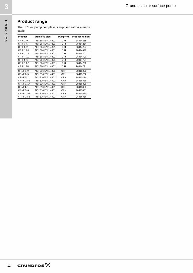
Product rangeThe CRFlex pump complete is supplied with a 2-metre cable.
Product Stainless steel Pump end Product number
CRIF 1-9 AISI 304/EN 1.4301 CRI 98414238
CRIF 3-5 AISI 304/EN 1.4301 CRI 98414264
CRIF 5-2 AISI 304/EN 1.4301 CRI 98414267
CRIF 10-1 AISI 304/EN 1.4301 CRI 98414699
CRIF 1-17 AISI 304/EN 1.4301 CRI 98414701
CRIF 3-11 AISI 304/EN 1.4301 CRI 98414709
CRIF 5-6 AISI 304/EN 1.4301 CRI 98414724
CRIF 10-2 AISI 304/EN 1.4301 CRI 98414726
CRIF 15-1 AISI 304/EN 1.4301 CRI 98414771
CRNF 1-9 AISI 316/EN 1.4401 CRN 98415280
CRNF 3-5 AISI 316/EN 1.4401 CRN 98415292
CRNF 5-2 AISI 316/EN 1.4401 CRN 98415294
CRNF 10-1 AISI 316/EN 1.4401 CRN 98415326
CRNF 1-17 AISI 316/EN 1.4401 CRN 98415305
CRNF 3-11 AISI 316/EN 1.4401 CRN 98415330
CRNF 5-6 AISI 316/EN 1.4401 CRN 98415331
CRNE 10-2 AISI 316/EN 1.4401 CRN 98415335
CRNF 15-1 AISI 316/EN 1.4401 CRN 98415336
Ap
pli
ca
tio
ns
Grundfos solar surface pump 4
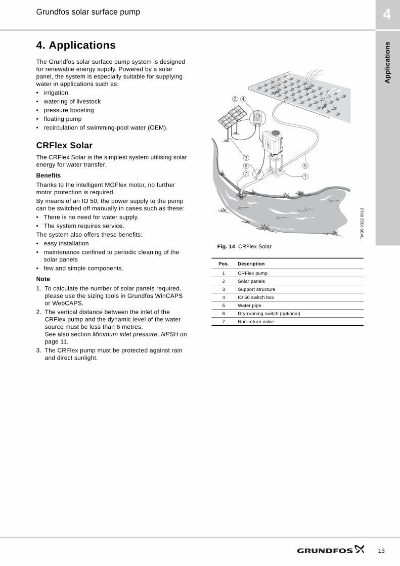
4. Applications
The Grundfos solar surface pump system is designed for renewable energy supply. Powered by a solar panel, the system is especially suitable for supplying water in applications such as:
• irrigation
• watering of livestock
• pressure boosting
• floating pump
• recirculation of swimming-pool water (OEM).
CRFlex SolarThe CRFlex Solar is the simplest system utilising solar energy for water transfer.
Benefits
Thanks to the intelligent MGFlex motor, no further motor protection is required.
By means of an IO 50, the power supply to the pump can be switched off manually in cases such as these:
• There is no need for water supply.
• The system requires service.
The system also offers these benefits:
• easy installation
• maintenance confined to periodic cleaning of the solar panels
• few and simple components.
Note
1. To calculate the number of solar panels required, please use the sizing tools in Grundfos WinCAPS or WebCAPS.
2. The vertical distance between the inlet of the CRFlex pump and the dynamic level of the water source must be less than 6 metres. See also section Minimum inlet pressure, NPSH on page 11.
3. The CRFlex pump must be protected against rain and direct sunlight.
Fig. 14 CRFlex Solar
TM
05
03
22
06
13
Pos. Description
1 CRFlex pump
2 Solar panels
3 Support structure
4 IO 50 switch box
5 Water pipe
6 Dry-running switch (optional)
7 Non-return valve
3
42
6
7
5
1
13
Ap
plic
atio
ns
14
Grundfos solar surface pump4
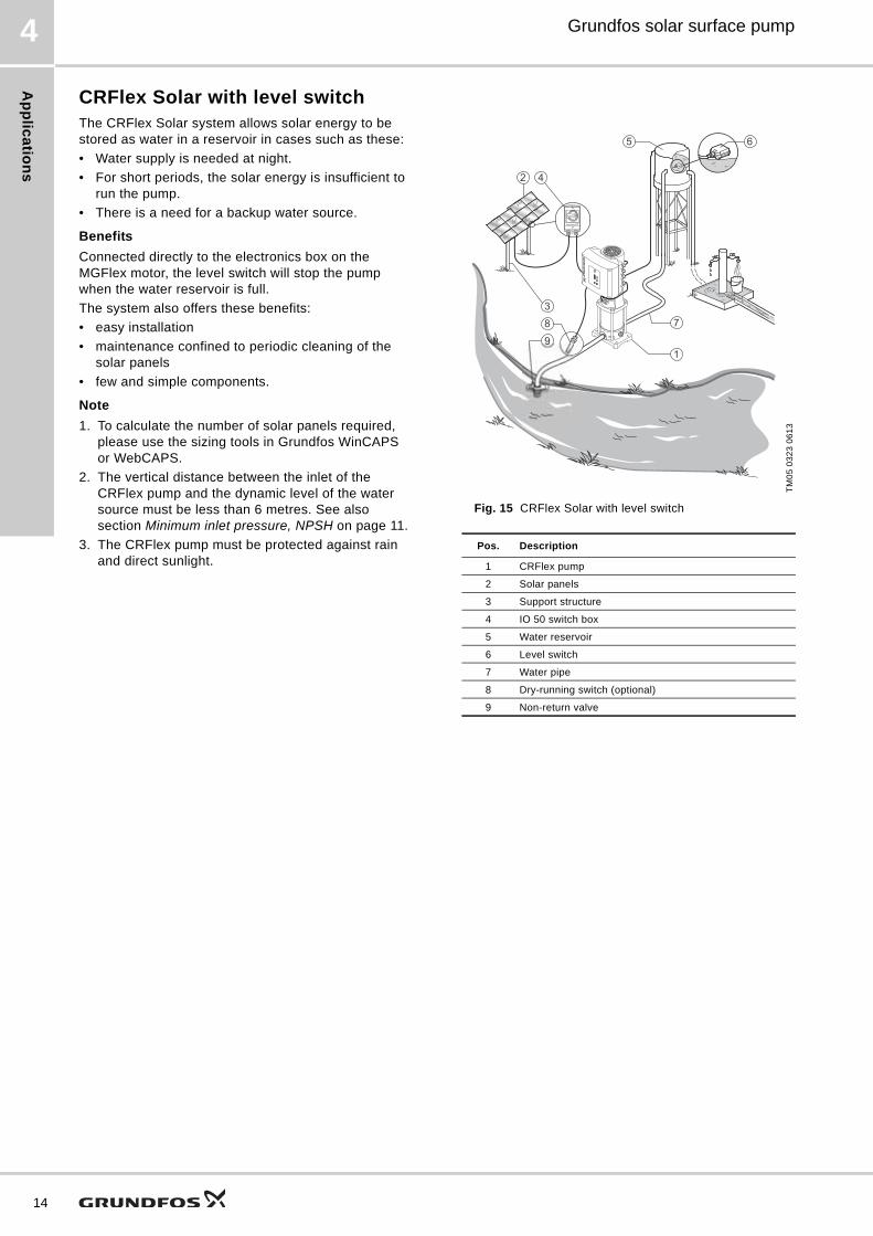
CRFlex Solar with level switchThe CRFlex Solar system allows solar energy to be stored as water in a reservoir in cases such as these:
• Water supply is needed at night.
• For short periods, the solar energy is insufficient to run the pump.
• There is a need for a backup water source.
Benefits
Connected directly to the electronics box on the MGFlex motor, the level switch will stop the pump when the water reservoir is full.
The system also offers these benefits:
• easy installation
• maintenance confined to periodic cleaning of the solar panels
• few and simple components.
Note
1. To calculate the number of solar panels required, please use the sizing tools in Grundfos WinCAPS or WebCAPS.
2. The vertical distance between the inlet of the CRFlex pump and the dynamic level of the water source must be less than 6 metres. See also section Minimum inlet pressure, NPSH on page 11.
3. The CRFlex pump must be protected against rain and direct sunlight.
Fig. 15 CRFlex Solar with level switch
TM
05
03
23
06
13
Pos. Description
1 CRFlex pump
2 Solar panels
3 Support structure
4 IO 50 switch box
5 Water reservoir
6 Level switch
7 Water pipe
8 Dry-running switch (optional)
9 Non-return valve
7
1
5 6
3
42
8
9
Ap
pli
ca
tio
ns
Grundfos solar surface pump 4
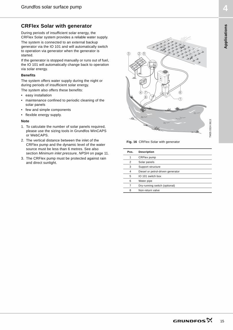
CRFlex Solar with generatorDuring periods of insufficient solar energy, the CRFlex Solar system provides a reliable water supply.
The system is connected to an external backup generator via the IO 101 and will automatically switch to operation via generator when the generator is started.
If the generator is stopped manually or runs out of fuel, the IO 101 will automatically change back to operation via solar energy.
Benefits
The system offers water supply during the night or during periods of insufficient solar energy.
The system also offers these benefits:
• easy installation
• maintenance confined to periodic cleaning of the solar panels
• few and simple components
• flexible energy supply.
Note
1. To calculate the number of solar panels required, please use the sizing tools in Grundfos WinCAPS or WebCAPS.
2. The vertical distance between the inlet of the CRFlex pump and the dynamic level of the water source must be less than 6 metres. See also section Minimum inlet pressure, NPSH on page 11.
3. The CRFlex pump must be protected against rain and direct sunlight.
Fig. 16 CRFlex Solar with generator
TM
05
03
24
06
13
Pos. Description
1 CRFlex pump
2 Solar panels
3 Support structure
4 Diesel or petrol-driven generator
5 IO 101 switch box
6 Water pipe
7 Dry-running switch (optional)
8 Non-return valve
52
6
1
3
4 7
8
15
Ap
plic
atio
ns
16
Grundfos solar surface pump4
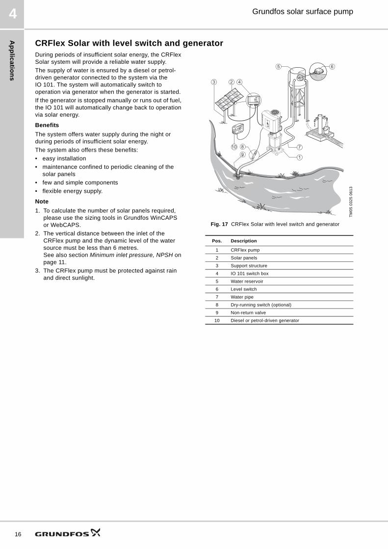
CRFlex Solar with level switch and generatorDuring periods of insufficient solar energy, the CRFlex Solar system will provide a reliable water supply.
The supply of water is ensured by a diesel or petrol-driven generator connected to the system via the IO 101. The system will automatically switch to operation via generator when the generator is started.
If the generator is stopped manually or runs out of fuel, the IO 101 will automatically change back to operation via solar energy.
Benefits
The system offers water supply during the night or during periods of insufficient solar energy.
The system also offers these benefits:
• easy installation
• maintenance confined to periodic cleaning of the solar panels
• few and simple components
• flexible energy supply.
Note
1. To calculate the number of solar panels required, please use the sizing tools in Grundfos WinCAPS or WebCAPS.
2. The vertical distance between the inlet of the CRFlex pump and the dynamic level of the water source must be less than 6 metres. See also section Minimum inlet pressure, NPSH on page 11.
3. The CRFlex pump must be protected against rain and direct sunlight.
Fig. 17 CRFlex Solar with level switch and generator
TM
05
03
25
06
13
Pos. Description
1 CRFlex pump
2 Solar panels
3 Support structure
4 IO 101 switch box
5 Water reservoir
6 Level switch
7 Water pipe
8 Dry-running switch (optional)
9 Non-return valve
10 Diesel or petrol-driven generator
7
1
5 6
423
10 8
9
Ap
pli
ca
tio
ns
Grundfos solar surface pump 4
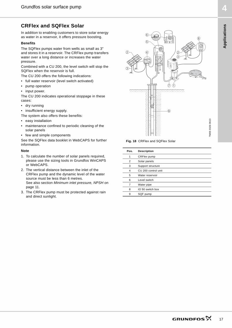
CRFlex and SQFlex SolarIn addition to enabling customers to store solar energy as water in a reservoir, it offers pressure boosting.
Benefits
The SQFlex pumps water from wells as small as 3" and stores it in a reservoir. The CRFlex pump transfers water over a long distance or increases the water pressure.
Combined with a CU 200, the level switch will stop the SQFlex when the reservoir is full.
The CU 200 offers the following indications:
• full water reservoir (level switch activated)
• pump operation
• input power.
The CU 200 indicates operational stoppage in these cases:
• dry running
• insufficient energy supply.
The system also offers these benefits:
• easy installation
• maintenance confined to periodic cleaning of the solar panels
• few and simple components
See the SQFlex data booklet in WebCAPS for further information.
Note
1. To calculate the number of solar panels required, please use the sizing tools in Grundfos WinCAPS or WebCAPS.
2. The vertical distance between the inlet of the CRFlex pump and the dynamic level of the water source must be less than 6 metres. See also section Minimum inlet pressure, NPSH on page 11.
3. The CRFlex pump must be protected against rain and direct sunlight.
Fig. 18 CRFlex and SQFlex Solar
TM
05
03
26
06
13
Pos. Description
1 CRFlex pump
2 Solar panels
3 Support structure
4 CU 200 control unit
5 Water reservoir
6 Level switch
7 Water pipe
8 IO 50 switch box
9 SQF pump
4
5
6
7 1
32
9
8
3
2
17
Ac
ce
ss
orie
s
18
Grundfos solar surface pump5
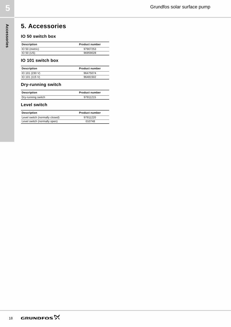
5. Accessories
IO 50 switch box
IO 101 switch box
Dry-running switch
Level switch
Description Product number
IO 50 (metric) 97907253
IO 50 (US) 96959028
Description Product number
IO 101 (230 V) 96475074
IO 101 (115 V) 96481502
Description Product number
Dry-running switch 97911215
Description Product number
Level switch (normally closed) 97911220
Level switch (normally open) 010748
Te
ch
nic
al
da
ta
Grundfos solar surface pump 6
6. Technical data
Dimensions and weights
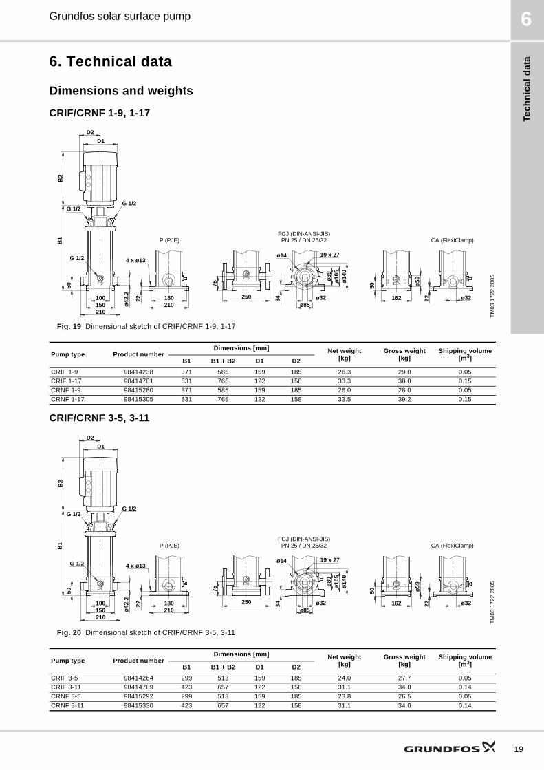
CRIF/CRNF 1-9, 1-17
Fig. 19 Dimensional sketch of CRIF/CRNF 1-9, 1-17
CRIF/CRNF 3-5, 3-11
Fig. 20 Dimensional sketch of CRIF/CRNF 3-5, 3-11
TM
03
17
22
28
05
P (PJE) CA (FlexiClamp)
ø59
162 ø32
50
22
G 1/2G 1/2
ø32
ø14
0
50
22 180
B1
B2
150100
210
ø10
5ø
89
210
4 x ø13G 1/2
D2
D1
250
ø42
.2
75
ø85
34
19 x 27ø14
PN 25 / DN 25/32FGJ (DIN-ANSI-JIS)
Pump type Product numberDimensions [mm] Net weight
[kg]Gross weight
[kg]Shipping volume
[m3]B1 B1 + B2 D1 D2
CRIF 1-9 98414238 371 585 159 185 26.3 29.0 0.05
CRIF 1-17 98414701 531 765 122 158 33.3 38.0 0.15
CRNF 1-9 98415280 371 585 159 185 26.0 28.0 0.05
CRNF 1-17 98415305 531 765 122 158 33.5 39.2 0.15
TM
03
17
22
28
05
P (PJE) CA (FlexiClamp)
ø59
162 ø32
50
22
G 1/2G 1/2
ø32
ø14
0
50
22 180
B1
B2
150100
210
ø10
5ø
89
210
4 x ø13G 1/2
D2
D1
250
ø42
.2
75
ø85
34
19 x 27ø14
PN 25 / DN 25/32FGJ (DIN-ANSI-JIS)
Pump type Product numberDimensions [mm] Net weight
[kg]Gross weight
[kg]Shipping volume
[m3]B1 B1 + B2 D1 D2
CRIF 3-5 98414264 299 513 159 185 24.0 27.7 0.05
CRIF 3-11 98414709 423 657 122 158 31.1 34.0 0.14
CRNF 3-5 98415292 299 513 159 185 23.8 26.5 0.05
CRNF 3-11 98415330 423 657 122 158 31.1 34.0 0.14
19
Te
ch
nic
al d
ata
20
Grundfos solar surface pump6
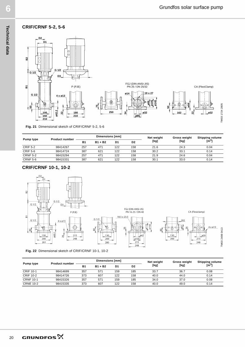
CRIF/CRNF 5-2, 5-6
Fig. 21 Dimensional sketch of CRIF/CRNF 5-2, 5-6
CRIF/CRNF 10-1, 10-2
Fig. 22 Dimensional sketch of CRIF/CRNF 10-1, 10-2
TM
03
17
24
28
05
P (PJE) CA (FlexiClamp)
D3
ø59
162 ø32
50
22
G 1/2G 1/2
ø32
ø14
0
50
22 180
B1
B2
150100
210
ø10
5ø
89
210
4 x ø13G 1/2
D2
D1
250
ø42
.2
75
ø85
34
19 x 27ø14
PN 25 / DN 25/32FGJ (DIN-ANSI-JIS)
Pump type Product numberDimensions [mm] Net weight
[kg]Gross weight
[kg]Shipping volume
[m3]B1 B1 + B2 D1 D2
CRIF 5-2 98414267 257 471 122 158 21.6 24.3 0.04
CRIF 5-6 98414724 387 621 122 158 30.2 33.1 0.14
CRNF 5-2 98415294 257 471 122 158 21.9 24.6 0.04
CRNF 5-6 98415331 387 621 122 158 30.1 33.0 0.14
TM
03
24
98
04
13
D3
130 ø60.
1
B2
D2D1
200
80
G 1/2
261
B1
G 1/2G 1/2
215248
18.5 x 23.5
26
PN 16-25 / DN 40
ø115
280
4 x ø13
CA (Flexiclamp)
26ø150
ø105ø42 ø50
202
ø87
80
P (PJE)
26
80
248215
200130 130
200
G 1/2
4 x ø13
248215
FGJ (DIN-ANSI-JIS)
Pump type Product numberDimensions [mm] Net weight
[kg]Gross weight
[kg]Shipping volume
[m3]B1 B1 + B2 D1 D2
CRIF 10-1 98414699 357 571 159 185 33.7 36.7 0.08
CRIF 10-2 98414726 373 607 122 158 40.0 44.0 0.14
CRNF 10-1 98415326 357 571 159 185 34.0 37.0 0.08
CRNE 10-2 98415335 373 607 122 158 40.0 49.0 0.14
Te
ch
nic
al
da
ta
Grundfos solar surface pump 6
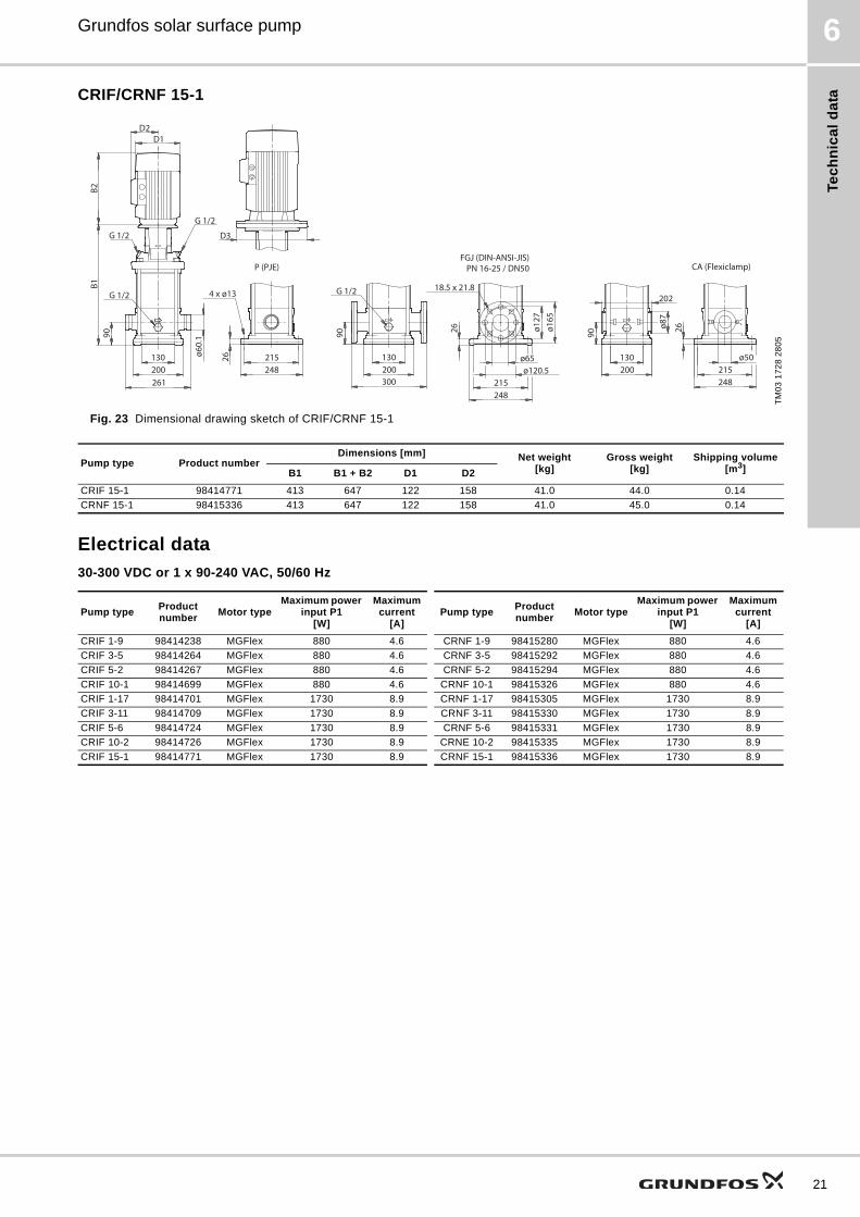
CRIF/CRNF 15-1
Fig. 23 Dimensional drawing sketch of CRIF/CRNF 15-1
Electrical data
30-300 VDC or 1 x 90-240 VAC, 50/60 Hz
TM
03
17
28
28
05
B2
D2D1
G 1/2
G 1/2 D3
B1
G 1/2
261
215248
18.5 x 21.8
PN 16-25 / DN50
ø127
300
4 x ø13
CA (Flexiclamp)
ø165
ø120.5ø65 ø50
202
ø87
90
P (PJE)
26
ø60.
1
200130
248215
215248
G 1/2
130200
130200
26
269090
FGJ (DIN-ANSI-JIS)
Pump type Product numberDimensions [mm] Net weight
[kg]Gross weight
[kg]Shipping volume
[m3]B1 B1 + B2 D1 D2
CRIF 15-1 98414771 413 647 122 158 41.0 44.0 0.14
CRNF 15-1 98415336 413 647 122 158 41.0 45.0 0.14
Pump typeProduct number
Motor typeMaximum power
input P1 [W]
Maximum current
[A]Pump type
Product number
Motor typeMaximum power
input P1 [W]
Maximum current
[A]
CRIF 1-9 98414238 MGFlex 880 4.6 CRNF 1-9 98415280 MGFlex 880 4.6
CRIF 3-5 98414264 MGFlex 880 4.6 CRNF 3-5 98415292 MGFlex 880 4.6
CRIF 5-2 98414267 MGFlex 880 4.6 CRNF 5-2 98415294 MGFlex 880 4.6
CRIF 10-1 98414699 MGFlex 880 4.6 CRNF 10-1 98415326 MGFlex 880 4.6
CRIF 1-17 98414701 MGFlex 1730 8.9 CRNF 1-17 98415305 MGFlex 1730 8.9
CRIF 3-11 98414709 MGFlex 1730 8.9 CRNF 3-11 98415330 MGFlex 1730 8.9
CRIF 5-6 98414724 MGFlex 1730 8.9 CRNF 5-6 98415331 MGFlex 1730 8.9
CRIF 10-2 98414726 MGFlex 1730 8.9 CRNE 10-2 98415335 MGFlex 1730 8.9
CRIF 15-1 98414771 MGFlex 1730 8.9 CRNF 15-1 98415336 MGFlex 1730 8.9
21
22
7 Grundfos solar surface pump
Cu
rve
co
nd
ition
s
Performance curves
7. Performance curves
Curve conditions
Specific performance charts
The specific performance charts on pages 22 to 31 are based on the following guidelines:
• Tolerances to ISO 9906, Annex A, if indicated.
• All curves show mean values.
• The curves must not be used as guarantee curves.
• Typical deviation: ± 15 %.
• The measurements have been made at a water temperature of +20 °C.
• The curves apply to a kinematic viscosity of 1 mm2/s (1 cSt). If the pump is used for liquids with a viscosity higher than that of water, this will reduce the head and increase the power consumption.
Pressure loss
The QH curves are inclusive of inlet and valve losses at actual speed.
NPSH curves
The NPSH curve is an average curve for all the variants shown. When sizing the pumps, add a safety margin of at least 0.5 m.
7Grundfos solar surface pump
CR
Fle
x 1
-9
Performance curves
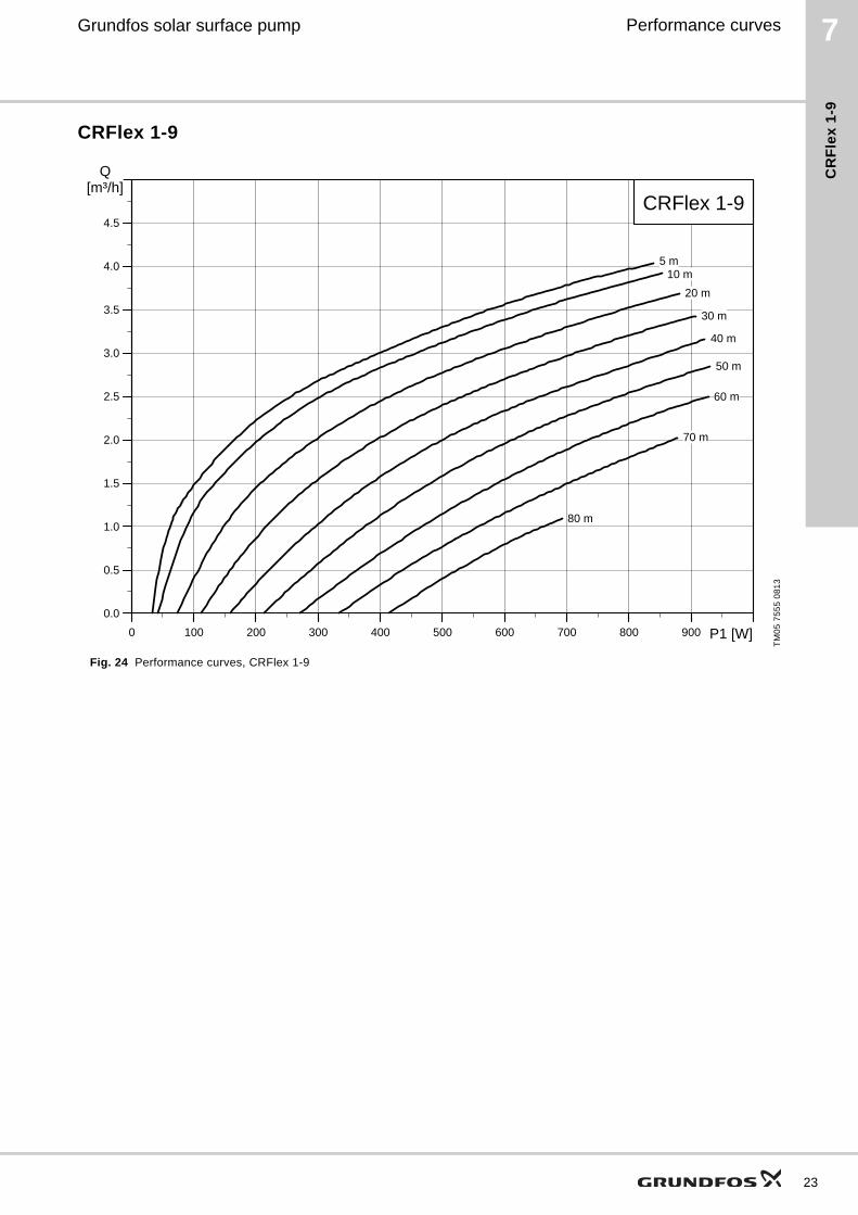
CRFlex 1-9
Fig. 24 Performance curves, CRFlex 1-9
TM
05
75
55
08
13
0 100 200 300 400 500 600 700 800 900 P1 [W]
0.0
0.5
1.0
1.5
2.0
2.5
3.0
3.5
4.0
4.5
[m³/h]Q
CRFlex 1-9
5 m10 m
20 m
30 m
40 m
50 m
60 m
70 m
80 m
23
24
7 Grundfos solar surface pump
CR
Fle
x 1
-17
Performance curves
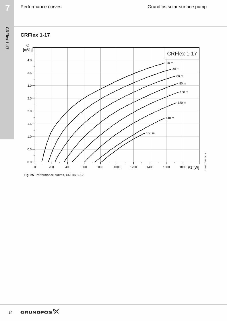
CRFlex 1-17
Fig. 25 Performance curves, CRFlex 1-17
TM
05
07
56
08
13
0 200 400 600 800 1000 1200 1400 1600 1800 P1 [W]
0.0
0.5
1.0
1.5
2.0
2.5
3.0
3.5
4.0
[m³/h]Q
CRFlex 1-17
20 m
40 m
60 m
80 m
100 m
120 m
140 m
150 m
7Grundfos solar surface pump
CR
Fle
x 3
-5
Performance curves
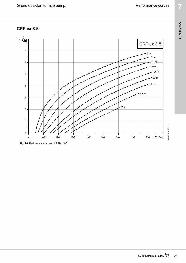
CRFlex 3-5
Fig. 26 Performance curves, CRFlex 3-5
TM
05
07
57
08
13
0 100 200 300 400 500 600 700 800 P1 [W]
0
1
2
3
4
5
6
7
[m³/h]Q
CRFlex 3-5
5 m
10 m
15 m
20 m
25 m
30 m
35 m
40 m
45 m
25
26
7 Grundfos solar surface pump
CR
Fle
x 3
-11
Performance curves
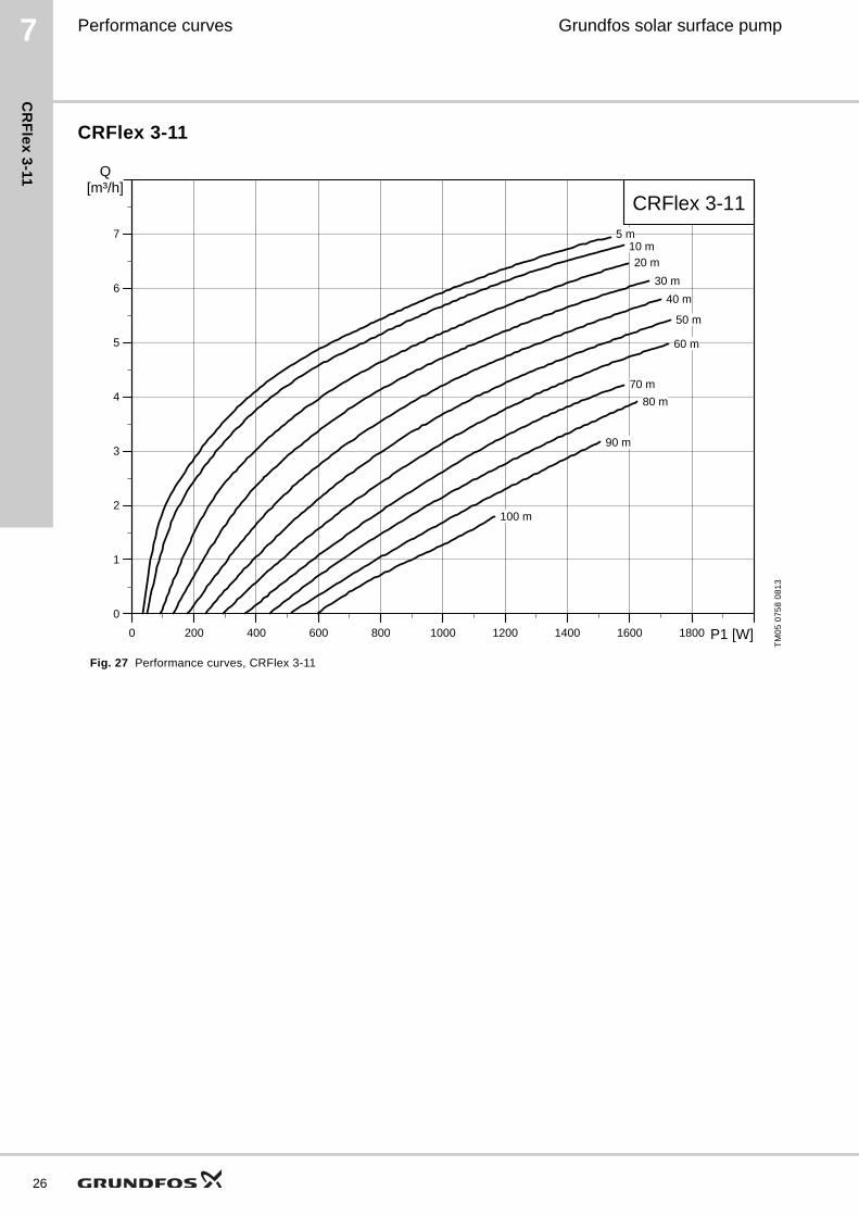
CRFlex 3-11
Fig. 27 Performance curves, CRFlex 3-11
TM
05
07
58
08
13
0 200 400 600 800 1000 1200 1400 1600 1800 P1 [W]
0
1
2
3
4
5
6
7
[m³/h]Q
CRFlex 3-115 m
10 m
20 m
30 m
40 m
50 m
60 m
70 m
80 m
90 m
100 m
7Grundfos solar surface pump
CR
Fle
x 5
-2
Performance curves
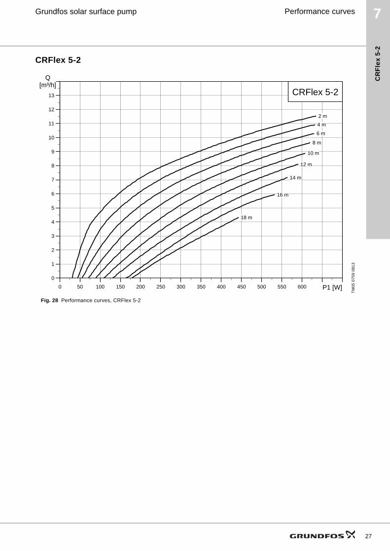
CRFlex 5-2
Fig. 28 Performance curves, CRFlex 5-2
TM
05
07
59
08
13
0 50 100 150 200 250 300 350 400 450 500 550 600 P1 [W]
0
1
2
3
4
5
6
7
8
9
10
11
12
13
[m³/h]Q
CRFlex 5-2
2 m
4 m
6 m
8 m
10 m
12 m
14 m
16 m
18 m
27
28
7 Grundfos solar surface pump
CR
Fle
x 5
-6
Performance curves
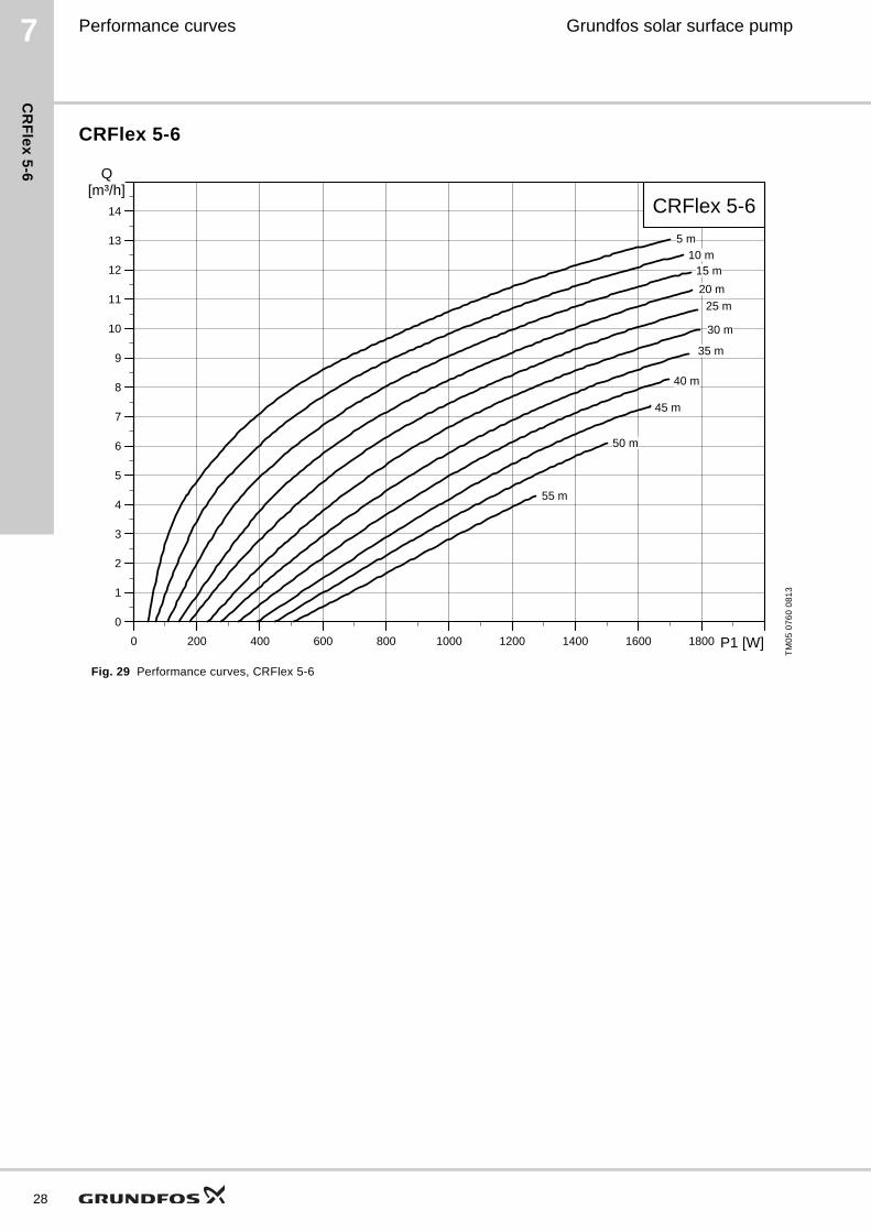
CRFlex 5-6
Fig. 29 Performance curves, CRFlex 5-6
TM
05
07
60
08
13
0 200 400 600 800 1000 1200 1400 1600 1800 P1 [W]
0
1
2
3
4
5
6
7
8
9
10
11
12
13
14
[m³/h]Q
CRFlex 5-6
5 m
10 m15 m
20 m
25 m
30 m
35 m
40 m
45 m
50 m
55 m
7Grundfos solar surface pump
CR
Fle
x 1
0-1
Performance curves
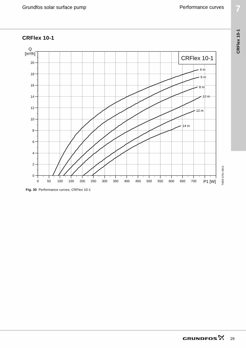
CRFlex 10-1
Fig. 30 Performance curves, CRFlex 10-1
TM
05
07
61
08
13
0 50 100 150 200 250 300 350 400 450 500 550 600 650 700 P1 [W]
0
2
4
6
8
10
12
14
16
18
20
[m³/h]Q
CRFlex 10-1
4 m
6 m
8 m
10 m
12 m
14 m
29
30
7 Grundfos solar surface pump
CR
Fle
x 1
0-2
Performance curves
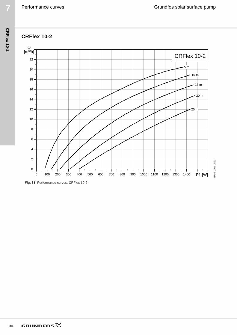
CRFlex 10-2
Fig. 31 Performance curves, CRFlex 10-2
TM
05
07
62
08
13
0 100 200 300 400 500 600 700 800 900 1000 1100 1200 1300 1400 P1 [W]
0
2
4
6
8
10
12
14
16
18
20
22
[m³/h]Q
CRFlex 10-2
5 m
10 m
15 m
20 m
25 m
7Grundfos solar surface pump
CR
Fle
x 1
5-1
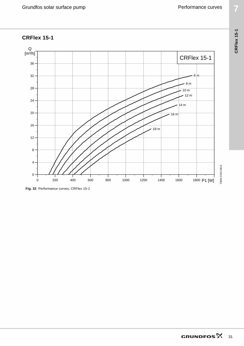
Performance curves
CRFlex 15-1
Fig. 32 Performance curves, CRFlex 15-1
TM
05
07
63
08
13
0 200 400 600 800 1000 1200 1400 1600 1800 P1 [W]
0
4
8
12
16
20
24
28
32
36
[m³/h]Q
CRFlex 15-1
6 m
8 m
10 m
12 m
14 m
16 m
18 m
31
32
8 Grundfos solar surface pump
Pe
rform
an
ce
cu
rve
s, C
RI, C
RN
1
Appendix
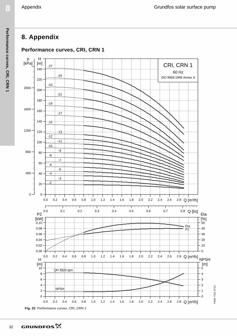
8. Appendix
Performance curves, CRI, CRN 1
Fig. 33 Performance curves, CRI, CRN 1
TM
02
73
11 0
71
3
0.0 0.2 0.4 0.6 0.8 1.0 1.2 1.4 1.6 1.8 2.0 2.2 2.4 2.6 2.8 Q [m³/h]
0
20
40
60
80
100
120
140
160
180
200
220
240
H[m]
0.0 0.1 0.2 0.3 0.4 0.5 0.6 0.7 0.8 Q [l/s]
0
400
800
1200
1600
2000
p[kPa] CRI, CRN 1
60 HzISO 9906:1999 Annex A
-2-3
-4-5
-6
-7
-8
-9
-10
-11
-12
-13
-15
-17
-19
-21
-23
-25
-27
0.0 0.2 0.4 0.6 0.8 1.0 1.2 1.4 1.6 1.8 2.0 2.2 2.4 2.6 2.8 Q [m³/h]
0.00
0.02
0.04
0.06
0.08
0.10
P2[kW]
0
10
20
30
40
50
Eta[%]
P2Eta
0.0 0.2 0.4 0.6 0.8 1.0 1.2 1.4 1.6 1.8 2.0 2.2 2.4 2.6 2.8 Q [m³/h]
0
2
4
6
8
10
H[m]
0
1
2
3
4
5
NPSH[m]
QH 3500 rpm
NPSH
8Grundfos solar surface pump
Pe
rfo
rma
nc
e c
urv
es
, C
RI,
CR
N 3
Appendix
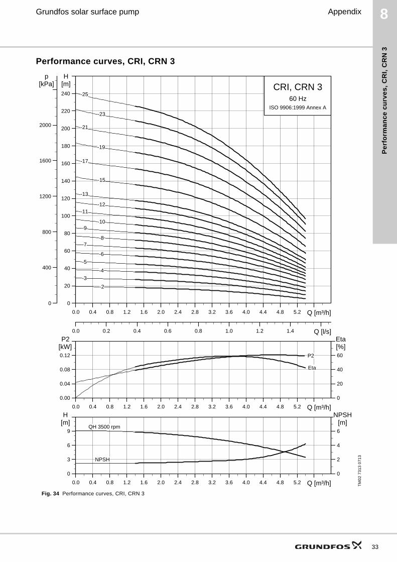
Performance curves, CRI, CRN 3
Fig. 34 Performance curves, CRI, CRN 3
TM
02
73
13
07
13
0.0 0.4 0.8 1.2 1.6 2.0 2.4 2.8 3.2 3.6 4.0 4.4 4.8 5.2 Q [m³/h]
0
20
40
60
80
100
120
140
160
180
200
220
240
H[m]
0.0 0.2 0.4 0.6 0.8 1.0 1.2 1.4 Q [l/s]
0
400
800
1200
1600
2000
p[kPa] CRI, CRN 3
60 HzISO 9906:1999 Annex A
-10
-11-12
-13
-15
-17
-19
-21
-23
-25
-3
-2
-4
-5
-6
-7-8
-9
0.0 0.4 0.8 1.2 1.6 2.0 2.4 2.8 3.2 3.6 4.0 4.4 4.8 5.2 Q [m³/h]
0.00
0.04
0.08
0.12
P2[kW]
0
20
40
60
Eta[%]
P2
Eta
0.0 0.4 0.8 1.2 1.6 2.0 2.4 2.8 3.2 3.6 4.0 4.4 4.8 5.2 Q [m³/h]
0
3
6
9
H[m]
0
2
4
6
NPSH[m]
QH 3500 rpm
NPSH
33
34
8 Grundfos solar surface pump
Pe
rform
an
ce
cu
rve
s, C
RI, C
RN
5
Appendix
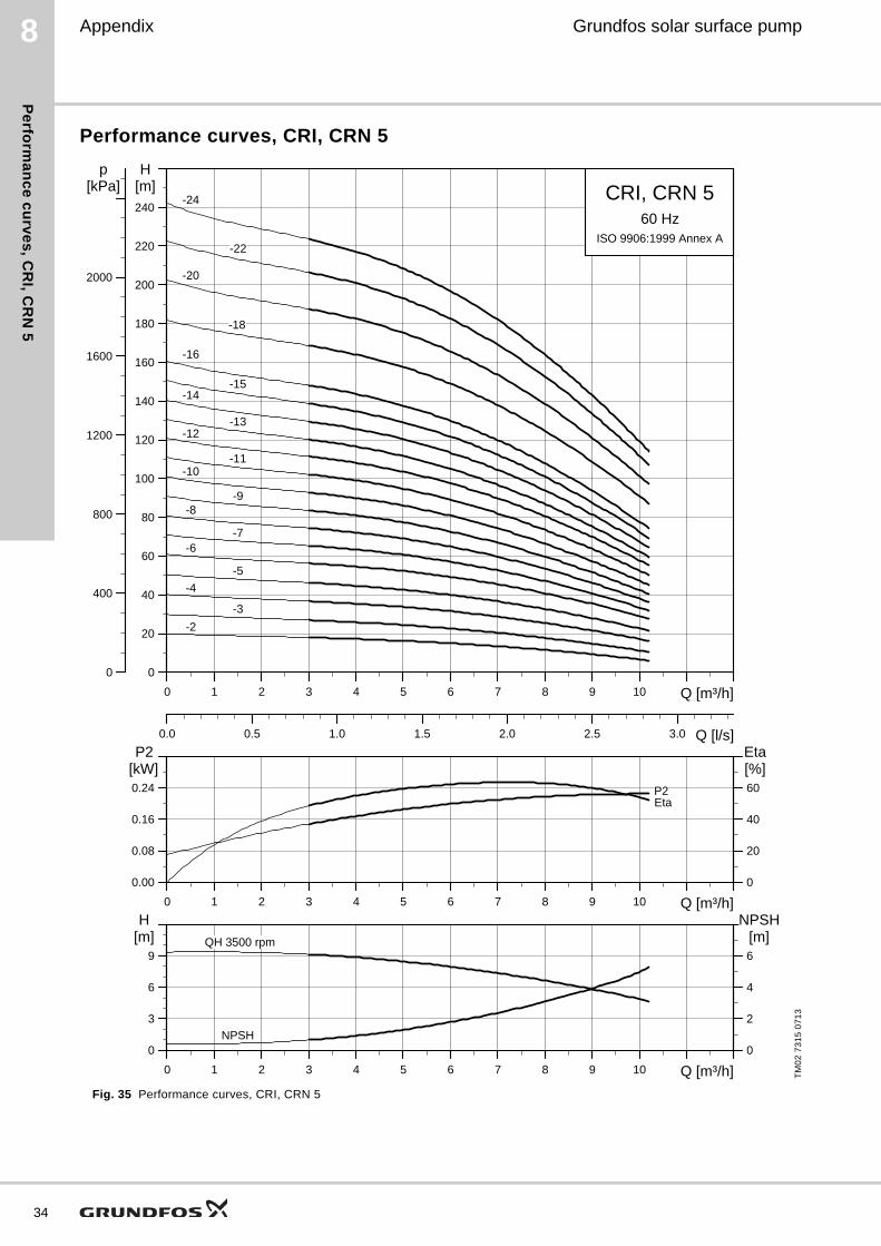
Performance curves, CRI, CRN 5
Fig. 35 Performance curves, CRI, CRN 5
TM
02
73
15
07
13
0 1 2 3 4 5 6 7 8 9 10 Q [m³/h]
0
20
40
60
80
100
120
140
160
180
200
220
240
H[m]
0.0 0.5 1.0 1.5 2.0 2.5 3.0 Q [l/s]
0
400
800
1200
1600
2000
p[kPa] CRI, CRN 5
60 HzISO 9906:1999 Annex A
-10-11
-12-13
-14-15
-16
-18
-2
-20
-22
-24
-3
-4
-5
-6-7
-8-9
0 1 2 3 4 5 6 7 8 9 10 Q [m³/h]
0.00
0.08
0.16
0.24
P2[kW]
0
20
40
60
Eta[%]
P2Eta
0 1 2 3 4 5 6 7 8 9 10 Q [m³/h]
0
3
6
9
H[m]
0
2
4
6
NPSH[m]QH 3500 rpm
NPSH
8Grundfos solar surface pump
Pe
rfo
rma
nc
e c
urv
es
, C
RI,
CR
N 1
0
Appendix
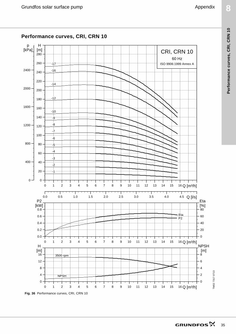
Performance curves, CRI, CRN 10
Fig. 36 Performance curves, CRI, CRN 10
TM
02
73
17
07
13
0 1 2 3 4 5 6 7 8 9 10 11 12 13 14 15 16 Q [m³/h]
0
20
40
60
80
100
120
140
160
180
200
220
240
260
280
H[m]
0.0 0.5 1.0 1.5 2.0 2.5 3.0 3.5 4.0 4.5 Q [l/s]
0
400
800
1200
1600
2000
2400
p[kPa] CRI, CRN 10
60 HzISO 9906:1999 Annex A
-10
-12
-14
-16
-17
-2
-3
-4
-5
-6
-7
-8
-9
-1
0 1 2 3 4 5 6 7 8 9 10 11 12 13 14 15 16 Q [m³/h]
0.0
0.2
0.4
0.6
0.8
P2[kW]
0
20
40
60
80
Eta[%]
P2Eta
0 1 2 3 4 5 6 7 8 9 10 11 12 13 14 15 16 Q [m³/h]
0
4
8
12
16
H[m]
0
2
4
6
8
NPSH[m]
3500 rpm
NPSH
35
36
8 Grundfos solar surface pump
Pe
rform
an
ce
cu
rve
s, C
RI, C
RN
15
Appendix
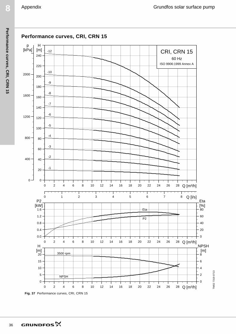
Performance curves, CRI, CRN 15
Fig. 37 Performance curves, CRI, CRN 15
TM
02
73
19
07
13
0 2 4 6 8 10 12 14 16 18 20 22 24 26 28 Q [m³/h]
0
20
40
60
80
100
120
140
160
180
200
220
240
H[m]
0 1 2 3 4 5 6 7 8 Q [l/s]
0
400
800
1200
1600
2000
p[kPa] CRI, CRN 15
60 HzISO 9906:1999 Annex A
-12
-10
-9
-8
-7
-6
-5
-4
-3
-2
-1
0 2 4 6 8 10 12 14 16 18 20 22 24 26 28 Q [m³/h]
0.0
0.4
0.8
1.2
1.6
P2[kW]
0
20
40
60
80
Eta[%]
Eta
P2
0 2 4 6 8 10 12 14 16 18 20 22 24 26 28 Q [m³/h]
0
5
10
15
20
H[m]
0
2
4
6
8
NPSH[m]
NPSH
3500 rpm
Fu
rth
er
pro
du
ct
do
cu
me
nta
tio
n
Grundfos solar surface pump 9
9. Further product documentation
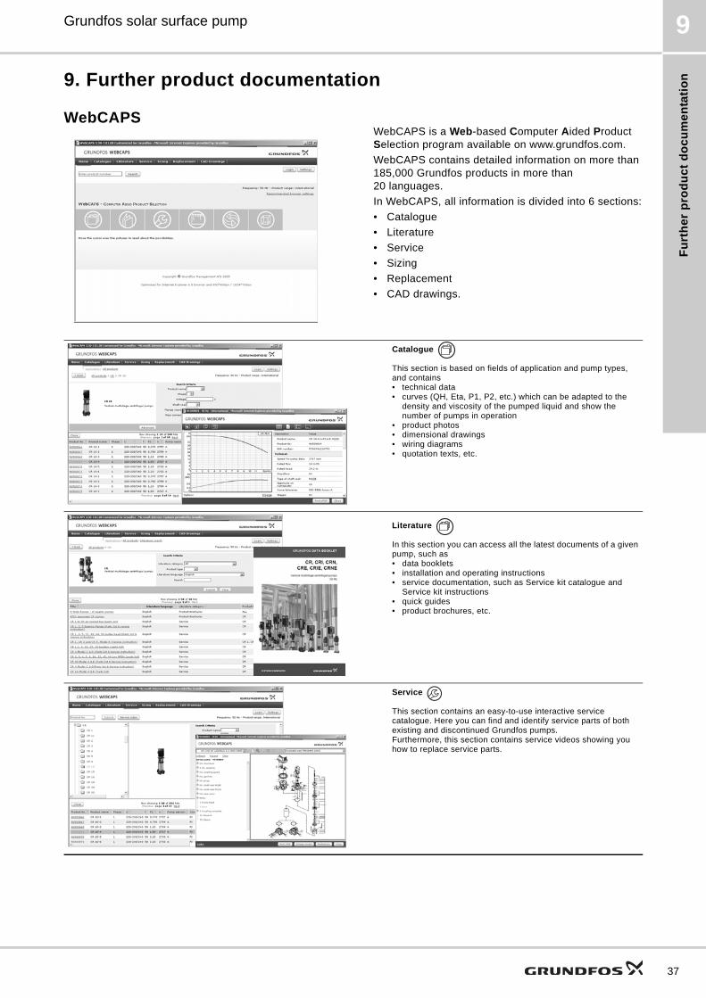
WebCAPSWebCAPS is a Web-based Computer Aided Product Selection program available on www.grundfos.com.
WebCAPS contains detailed information on more than 185,000 Grundfos products in more than 20 languages.
In WebCAPS, all information is divided into 6 sections:
• Catalogue
• Literature
• Service
• Sizing
• Replacement
• CAD drawings.
Catalogue
This section is based on fields of application and pump types, and contains • technical data• curves (QH, Eta, P1, P2, etc.) which can be adapted to the
density and viscosity of the pumped liquid and show the number of pumps in operation
• product photos• dimensional drawings• wiring diagrams• quotation texts, etc.
Literature
In this section you can access all the latest documents of a given pump, such as• data booklets• installation and operating instructions• service documentation, such as Service kit catalogue and
Service kit instructions• quick guides• product brochures, etc.
Service
This section contains an easy-to-use interactive service catalogue. Here you can find and identify service parts of both existing and discontinued Grundfos pumps.Furthermore, this section contains service videos showing you how to replace service parts.
37
Fu
rthe
r pro
du
ct d
oc
um
en
tatio
n
38
Grundfos solar surface pump9
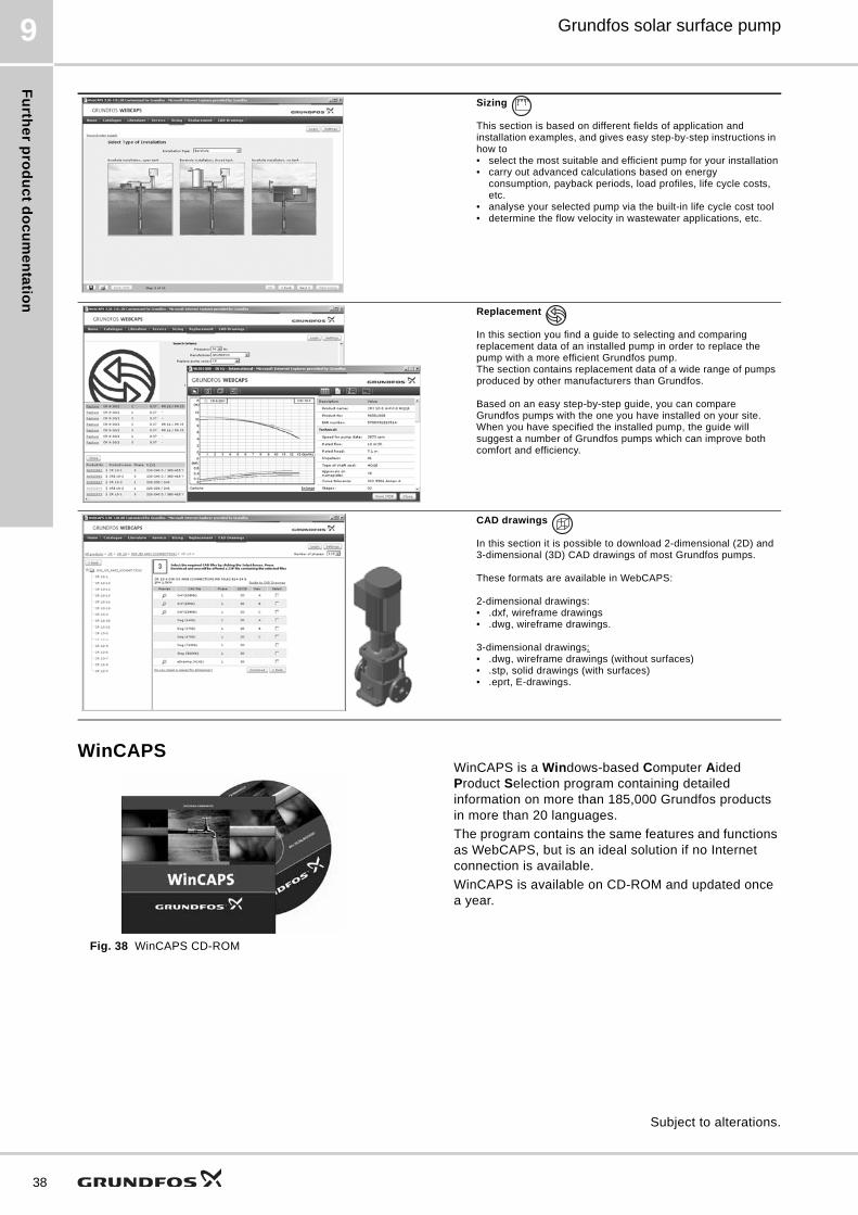
WinCAPS
Fig. 38 WinCAPS CD-ROM
WinCAPS is a Windows-based Computer Aided Product Selection program containing detailed information on more than 185,000 Grundfos products in more than 20 languages.
The program contains the same features and functions as WebCAPS, but is an ideal solution if no Internet connection is available.
WinCAPS is available on CD-ROM and updated once a year.
Sizing
This section is based on different fields of application and installation examples, and gives easy step-by-step instructions in how to• select the most suitable and efficient pump for your installation• carry out advanced calculations based on energy
consumption, payback periods, load profiles, life cycle costs, etc.
• analyse your selected pump via the built-in life cycle cost tool• determine the flow velocity in wastewater applications, etc.
Replacement
In this section you find a guide to selecting and comparing replacement data of an installed pump in order to replace the pump with a more efficient Grundfos pump. The section contains replacement data of a wide range of pumps produced by other manufacturers than Grundfos.
Based on an easy step-by-step guide, you can compare Grundfos pumps with the one you have installed on your site. When you have specified the installed pump, the guide will suggest a number of Grundfos pumps which can improve both comfort and efficiency.
CAD drawings
In this section it is possible to download 2-dimensional (2D) and 3-dimensional (3D) CAD drawings of most Grundfos pumps.
These formats are available in WebCAPS:
2-dimensional drawings:• .dxf, wireframe drawings• .dwg, wireframe drawings.
3-dimensional drawings:• .dwg, wireframe drawings (without surfaces)• .stp, solid drawings (with surfaces)• .eprt, E-drawings.
0 1
Subject to alterations.

39

GRUNDFOS A/S DK-8850 Bjerringbro . DenmarkTelephone: +45 87 50 14 00www.grundfos.com
97919030 0413
ECM: 1113381 Th
e n
am
e G
run
dfo
s, t
he
Gru
nd
fos
log
o,
an
d b
e t
hin
k i
nn
ov
ate
are
re
gis
tere
d t
rad
em
ark
s o
wn
ed
by
Gru
nd
fos
Ho
ldin
g A
/S o
r G
run
dfo
s A
/S,
De
nm
ark
. A
ll ri
gh
ts r
ese
rve
d w
orl
dw
ide
.©
Co
pyr
igh
t G
run
dfo
s H
old
ing
A/S