renice e7 2.5 44pin pata ssd datasheet - suntex.co.jp e7 2.5” 44pin pata ssd datasheet. ... oldest...
TRANSCRIPT

2011
Sun YongQing
Renice Technology Co.,Limited
2011-5-30
RENICE E7 2.5” 44pin PATA SSD Datasheet

Renice Technology Co., Limited
2
CATALOGUE
1. Introduction ............................................................................... 4
1.1 Product Overview ...................................................................................................................... 4
1.2 Feature ........................................................................................................................................ 4
2. Functional Block Diagram ....................................................... 5
3. Product Specifications ............................................................. 6
3.1 Physical Specifications ................................................................................................................ 6
3.2 Host Interface ................................................................................................................................ 7
3.3 Internal MROM for Boot-loader .................................................................................................. 7
3.4 H/W Acceleration Engine ............................................................................................................. 7
3.5 Mobile SDRAM Interface ............................................................................................................. 7
4. Interface Description ................................................................ 8
4.1 Pin Assignment ............................................................................................................................. 8
4.2 Pin Description .............................................................................................................................. 8
5. Electric Specifications ............................................................. 9
5.1 Power Specification ...................................................................................................................... 9
5.2 Power Supply Voltage .................................................................................................................. 9
5.3 Power Consumption (typical) ...................................................................................................... 9
6. Reliability Specification ......................................................... 10
6.1 Wear-leveling .............................................................................................................................. 10
6.2 H/W ECC and EDC for NAND Flash ....................................................................................... 10
6.3 MTBF ............................................................................................................................................ 10
7. Supported ATA Command Lists ........................................... 11
8. SMART ..................................................................................... 11
8.1 SMART subcommand sets ........................................................................................................ 11
8.2 SMART Read Data (subcommand D0h) ................................................................................. 12
8.2.1 Device Attribute Data Structure ..................................................................................... 12
8.2.2 Individual Attribute Data Structure ................................................................................ 12
8.2.3 Attribute ID Numbers ...................................................................................................... 12
8.3 SMART Save Attribute Values (subcommand D3h) .............................................................. 13
8.4 SMART Execute Off-line Immediately (subcommand D4h) ................................................. 13
8.5 SMART Read Log Sector (subcommand D5h) ...................................................................... 13
8.5.1 SMART Log Directory ..................................................................................................... 13

Renice Technology Co., Limited
3
8.5.2 SMART summary error log sector ................................................................................ 14
8.5.3 Self-test log structure ...................................................................................................... 15
8.5.4 Selective self-test log structure ..................................................................................... 15
8.6 SMART Write Log Sector (subcommand D6h) ...................................................................... 16
8.7 SMART Enable Operations (subcommand D8h) ................................................................... 16
8.8 SMART Disable Operations (subcommand D9h) .................................................................. 16
8.9 SMART Return Status (subcommand DAh) ........................................................................... 16
8.10 SMART Enable/Disable Automatic Off-line (subcommand DBh) ...................................... 16
9. Security ................................................................................... 17
9.1 Default setting ............................................................................................................................. 17
9.2 Initial setting of the user password ........................................................................................... 17
9.3 SECURITY mode operation from power-on ........................................................................... 17
9.4 Password lost .............................................................................................................................. 18
10. PATA Optional Features ...................................................... 18
10.1 Power Segment Pin P11 ......................................................................................................... 18
10.2 Asynchronous Signal Recovery ............................................................................................. 18
11. Identify Device Parameters .................................................. 19
12. Ordering Information ............................................................ 21
13. Part Number Naming Rule ................................................... 22
14. Master/Slave disc setting instructions ............................... 23
15. Secure erase direction for use ............................................ 23

Renice Technology Co., Limited
4
1. Introduction
1.1 Product Overview
Renice E7 IDE 2.5” SSD (Solid State Drive) is a high performance and high reliability storage
device based on NAND Flash technology that designed to solve the bottleneck of computing
system by traditional hard disk drives. Renice E7 IDE 2.5’’ SSD doesn't have a moving parts and
it has a same host interface and same physical dimension with Hard Disk Drive, So it can be
drop-in replaced with the hard disk drives without anything. With a high performance and low
power consumption, Renice E7 IDE 2.5’’ SSD can be a good storage device for NB and Tabletop
PC ,Renice E7 IDE 2.5’’ SSD purely consists of semiconductor devices and NAND flash
memories, which give rugged features against shock and vibration use in extreme environment
such as industrial PC an increased MTBF. Further more, Renice E7 IDE 2.5’’ SSD has highly
advanced flash memory management algorithm to guarantee higher performance and data
integrity.
1.2 Feature
● Performance
Read/Write Speed: Up to 120MB/90MB/s (MLC)
Up to 120MB/110MB/s (SLC)
● Form factor: 2.5-inch (100.0mm x 70.0mm x 9.5mm) L×W×H
● Interface standard: 44pin PATA
● Density: 16GB~240GB(MLC) 8GB~256GB(SLC)
● Input voltage: 5.0V (±5%)
● Standard operating temperature range from 0 to +70°C
● Industrial operating temperature range from -40 to +85°C
● Flash management algorithm: static and dynamic wear-leveling, bad block management
algorithm
● Supports dynamic power management and SMART (Self-Monitoring, Analysis and Reporting
Technology)
● H/W ECC and EDC for NAND Flash: Max. 18bit ECC BCH
● MTBF: >1,500,000 Hours

Renice Technology Co., Limited
5
2. Functional Block Diagram
Figure 1: Block Diagram

Renice Technology Co., Limited
6
3. Product Specifications
3.1 Physical Specifications
Form factor 2.5 inch
Dimensions(mm)
Length 100.20±0.25
Width 70.00±0.25
Height 9.20±0.25
Weight <70g
Connector 44pin PATA connector
Figure 2: Mechanical Diagram

Renice Technology Co., Limited
7
3.2 Host Interface
- Fully compliant with IDE44 connector,
- Fully compliant with ATA-7 Standard
- 8-bit/16-bit parallel interface
- supports PIO Modes 0-4
- supports Multiword DMA Modes 0-2
- supports Ultra DMA Modes 0-6
- Asynchronous Signal Recovery
- Device Activity Signal
3.3 Internal MROM for Boot-loader
Robust Firmware Corruption
Maintenance and diagnostics program in MROM for recovering from drive malfunction
3.4 H/W Acceleration Engine
Internal SRAM and external DRAM search engine
3.5 Mobile SDRAM Interface
16MB ~ 64MB buffer memory by Flash capacity

Renice Technology Co., Limited
8
4. Interface Description
4.1 Pin Assignment
4.2 Pin Description
Pin No Pin Name Pin No Pin Name Pin No Pin Name Pin No Pin Name
1 ATDEVICE 14 D10 27 DMARQ 40 DIAG
2 GND 15 D4 28 GND 41 DA0
3 NC 16 D11 29 DIOW 42 DA2
4 ATCSELEN 17 D3 30 GND 43 CS0
5 DUMMY 18 D12 31 DIOR 44 CS1
6 DUMMY 19 D2 32 GND 45 DASP
7 RESET 20 D13 33 DIORDY 46 GND
8 GND 21 D1 34 ATCSEL 47 5.0V
9 D7 22 D14 35 DMACK 48 5.0V
10 D8 23 D0 36 GND 49 GND
11 D6 24 D15 37 INTRQ 50 NC
12 D9 25 GND 38 NC
13 D5 26 DUMMY 39 DA1
Renice Technology Co., Limited
9
5. Electric Specifications
5.1 Power Specification
Operating voltage: 5.0V (±5%)
5.2 Power Supply Voltage
1.8V for Core, 3.3V for NAND, 1.8V for SDRAM
5.3 Power Consumption (typical)
Operation (Read/Write) – 1W
Idle – 0.5W
Standby – 0.5W
Sleep – 0.2W

Renice Technology Co., Limited
10
6. Reliability Specification
6.1 Wear-leveling
Renice SSD support both static and dynamic wear-leveling, these two algorithms guarantee all
type of flash memory at same level of erase cycles to improve lifetime limitation of NAND based
storage
6.2 H/W ECC and EDC for NAND Flash
Max. 18bit ECC BCH
6.3 MTBF
MTBF(Mean Time between Failures) of Renice SSD: >1,500,000 hours
Data retention at 25°C of Renice E7 SSD: >10 years
Item Features
Temperature Operation
Standard: 0~70°C
Industrial: -40~+85°C
Storage -55~+95°C
Humidity 5-95%
Vibration 10Hz-2000Hz, 16.4 G (X, Y, Z axis, 1 hour /axis)
Shock Peak Acceleration: 1,500 G, 0.5ms(Half-sine wave, ±X,±Y,±Z axis, 1 time/axis)
Peak Acceleration: 50 G, 11ms(Half-sine wave, ±X,±Y,±Z axis, 3 times/axis)

Renice Technology Co., Limited
11
7. Supported ATA Command Lists
8. SMART
8.1 SMART subcommand sets
In order to select a subcommand the host must write the subcommand code to the device's
Features Register before issuing the SMART Function Set command. The subcommands are
listed below.

Renice Technology Co., Limited
12
8.2 SMART Read Data (subcommand D0h)
This subcommand returns the device's Attribute Values to the host. The Attribute Values consist
of 512bytes.
8.2.1 Device Attribute Data Structure
8.2.2 Individual Attribute Data Structure
8.2.3 Attribute ID Numbers
1) indicates that the corresponding Attribute Values is fixed value for compatibility.
2) Remaining Life [%] = MIN(Remaining Life by Erase Count, Remaining Life by Bad Block)
-. Remaining Life by Erase Count = 100 – (average erase count / Max_PE_Count)
-. Remaining Life by Bad Block = 100 – (runtime bad block number of Bad Bank / Bad_BLK_Max of Bad Bank)
-. Max_PE_Count is defined by NAND Flash specification
-. Bad_BLK_Max is the number defined by firmware excluding the initial bad blocks.
Renice Technology Co., Limited
13
-. Bad Bank is the bank which has the biggest number of bad blocks among banks.
8.3 SMART Save Attribute Values (subcommand D3h)
This subcommand causes the device to immediately save any updated Attribute Values to the
device's Attribute Data sector regardless of the state of the Attribute Autosave feature.
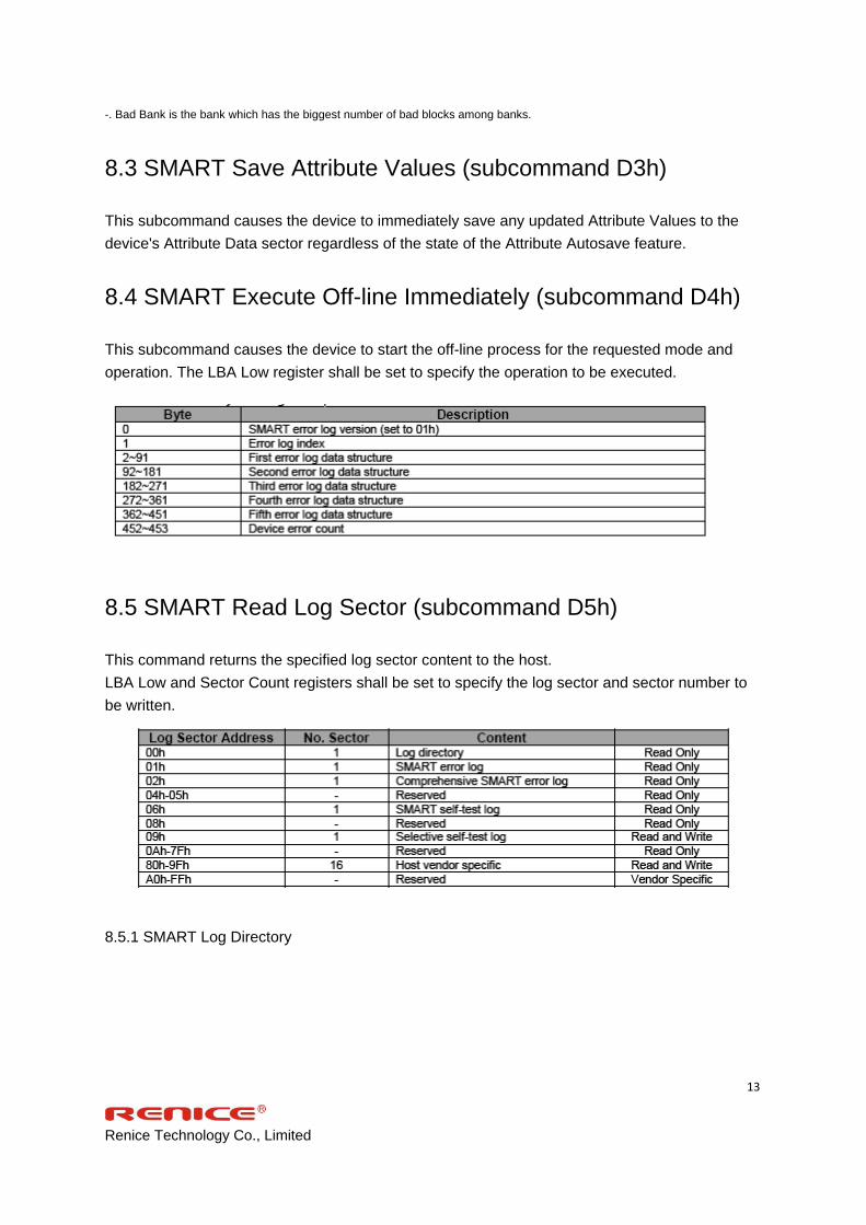
8.4 SMART Execute Off-line Immediately (subcommand D4h)
This subcommand causes the device to start the off-line process for the requested mode and
operation. The LBA Low register shall be set to specify the operation to be executed.
8.5 SMART Read Log Sector (subcommand D5h)
This command returns the specified log sector content to the host.
LBA Low and Sector Count registers shall be set to specify the log sector and sector number to
be written.
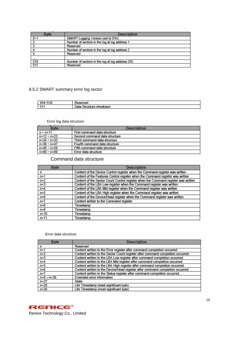
8.5.1 SMART Log Directory
Renice Technology Co., Limited
14
8.5.2 SMART summary error log sector
Error log data structure
Command data structure
Error data structure

Renice Technology Co., Limited
15
State field values
8.5.3 Self-test log structure
N is 0 through 20.
The data structure contains the descriptor of the Self-test that the device has performed. Each descriptor is 24 bytes long
and the self-test data structure is capable to contain up to 21 descriptors. After 21 descriptors has been recorded, the
oldest descriptor will be overwritten with the new descriptor. The self-test log pointer points to the most recent descriptor.
When there is no descriptor, the value is 0. When there are descriptor(s), the value is 1 through 21.
8.5.4 Selective self-test log structure
Renice Technology Co., Limited
16
8.6 SMART Write Log Sector (subcommand D6h)
This command writes 512 bytes of data to the specified log sector. LBA Low and Sector Count
registers shall be set to specify the log address and sector number to be written.
8.7 SMART Enable Operations (subcommand D8h)
This subcommand enables access to all SMART capabilities. Prior to receipt of a SMART Enable
Operations subcommand, Attribute Values are neither monitored nor saved by the device. The
state of SMART—either enabled or disabled—will be preserved by the device across power
cycles. Once enabled, the receipt of subsequent SMART Enable Operations subcommands will
not affect any of the Attribute Values.
8.8 SMART Disable Operations (subcommand D9h)
This subcommand disables all SMART capabilities. After receipt of this subcommand the device
disables all SMART operations. Non self-preserved Attribute Values will no longer be monitored.
The state of SMART—either enabled or disabled—is preserved by the device across power
cycles. Note that this subcommand does not preclude the device's power mode attribute auto
saving.
After receipt of the SMART Disable Operations subcommand from the host, all other SMART
subcommands except SMART Enable Operations are disabled and will be aborted by the device
returning the error code as specified in ―SMART Error Codes‖.
Any Attribute Values accumulated and saved to volatile memory prior to receipt of the SMART
Disable Operations command will be preserved in the device's Attribute Data Sectors. If the
device is re-enabled, these Attribute Values will be updated, as needed, upon receipt of a SMART
Read Attribute Values or a SMART Save Attribute Values command.
8.9 SMART Return Status (subcommand DAh)
This subcommand is used to communicate the reliability status of the device to the host's request.
Upon receipt of the SMART Return Status subcommand the device saves any updated Attribute
Values to the reserved sector, and compares the updated Attribute Values to the Attribute
Thresholds.
8.10 SMART Enable/Disable Automatic Off-line (subcommand
DBh)
Renice Technology Co., Limited
17
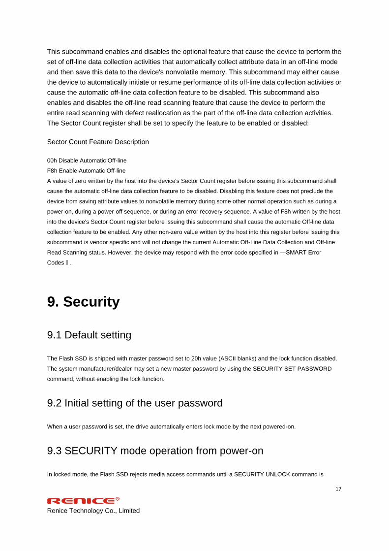
This subcommand enables and disables the optional feature that cause the device to perform the
set of off-line data collection activities that automatically collect attribute data in an off-line mode
and then save this data to the device's nonvolatile memory. This subcommand may either cause
the device to automatically initiate or resume performance of its off-line data collection activities or
cause the automatic off-line data collection feature to be disabled. This subcommand also
enables and disables the off-line read scanning feature that cause the device to perform the
entire read scanning with defect reallocation as the part of the off-line data collection activities.
The Sector Count register shall be set to specify the feature to be enabled or disabled:
Sector Count Feature Description
00h Disable Automatic Off-line
F8h Enable Automatic Off-line
A value of zero written by the host into the device's Sector Count register before issuing this subcommand shall
cause the automatic off-line data collection feature to be disabled. Disabling this feature does not preclude the
device from saving attribute values to nonvolatile memory during some other normal operation such as during a
power-on, during a power-off sequence, or during an error recovery sequence. A value of F8h written by the host
into the device's Sector Count register before issuing this subcommand shall cause the automatic Off-line data
collection feature to be enabled. Any other non-zero value written by the host into this register before issuing this
subcommand is vendor specific and will not change the current Automatic Off-Line Data Collection and Off-line
Read Scanning status. However, the device may respond with the error code specified in ―SMART Error
Codes‖.
9. Security
9.1 Default setting
The Flash SSD is shipped with master password set to 20h value (ASCII blanks) and the lock function disabled.
The system manufacturer/dealer may set a new master password by using the SECURITY SET PASSWORD
command, without enabling the lock function.
9.2 Initial setting of the user password
When a user password is set, the drive automatically enters lock mode by the next powered-on.
9.3 SECURITY mode operation from power-on
In locked mode, the Flash SSD rejects media access commands until a SECURITY UNLOCK command is

Renice Technology Co., Limited
18
successfully completed.
9.4 Password lost
If the user password is lost and High level security is set, the drive does not allow the user to access any data.
However, the drive can be unlocked using the master password.
If the user password is lost and Maximum security level is set, it is impossible to access data. However, the drive
can be unlocked using the ERASE UNIT command with the master password. The drive will erase all user data
and unlock the drive.
10. PATA Optional Features
10.1 Power Segment Pin P11
Pin P11 of the power segment of the device connector may be used by the device to provide the host with an
activity indication. The activity indication provided by pin P11 is primarily for use in backplane applications.
10.2 Asynchronous Signal Recovery
Phy may support asynchronous signal recovery for those applications where the usage model of device insertion
into a receptacle(power applied at time of insertion) does not apply.
When signal is lost, both the host and the device may attempt to recover the signal. A host or device shall
determine loss of signal as represented by a transition from PHYRDY to PHYRDYn, which is associated with
entry into states LSI: NoCommErr or LS2:NoComm within the Link layer. Note that negation of PHYRDY does not
always constitute a loss of signal. Recovery of the signal is associated with exit from state LS2:NoComm.
If the device attempts to recover the signal before the host by issuing a COMINIT, the device shall return its
signature following completion of the OOB sequence which included COMINIT. If a host supports synchronous
signal recovery, when the host receives an unsolicited COMINIT, the host shall issue a COMRESET to the device.
An unsolicited COMINIT is a COMINIT that was not in response to a preceding COMRESET, as defined by the
host not being in the HP2:HR_AwaitCOMINIT state when the COMINIT signal is first received.
When a COMRESET is sent to the device in response to an unsolicited COMINIT, the host shall set the Status
register to 7Fh and shall set all other Shadow Command Block Registers to FFh. When the COMINIT is received
in response to the COMRESET which is associated with entry into state HP2B:HR_AwaitNoCOMINIT, the
Shadow Status register value shall be updated to either FFh or 80h to reflect that a device is attached.
Renice Technology Co., Limited
19
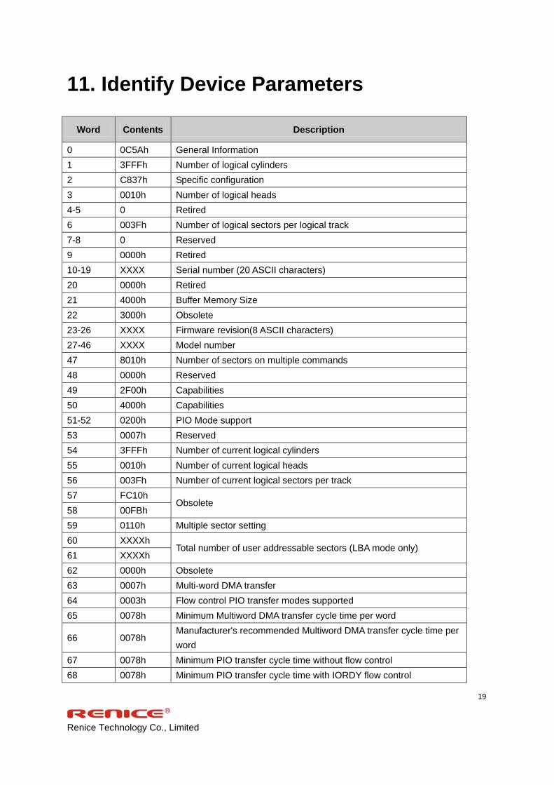
11. Identify Device Parameters
Word Contents Description
0 0C5Ah General Information
1 3FFFh Number of logical cylinders
2 C837h Specific configuration
3 0010h Number of logical heads
4-5 0 Retired
6 003Fh Number of logical sectors per logical track
7-8 0 Reserved
9 0000h Retired
10-19 XXXX Serial number (20 ASCII characters)
20 0000h Retired
21 4000h Buffer Memory Size
22 3000h Obsolete
23-26 XXXX Firmware revision(8 ASCII characters)
27-46 XXXX Model number
47 8010h Number of sectors on multiple commands
48 0000h Reserved
49 2F00h Capabilities
50 4000h Capabilities
51-52 0200h PIO Mode support
53 0007h Reserved
54 3FFFh Number of current logical cylinders
55 0010h Number of current logical heads
56 003Fh Number of current logical sectors per track
57 FC10h Obsolete
58 00FBh
59 0110h Multiple sector setting
60 XXXXh Total number of user addressable sectors (LBA mode only)
61 XXXXh
62 0000h Obsolete
63 0007h Multi-word DMA transfer
64 0003h Flow control PIO transfer modes supported
65 0078h Minimum Multiword DMA transfer cycle time per word
66 0078h Manufacturer's recommended Multiword DMA transfer cycle time per
word
67 0078h Minimum PIO transfer cycle time without flow control
68 0078h Minimum PIO transfer cycle time with IORDY flow control

Renice Technology Co., Limited
20
69-74 0 Reserved
75 001Fh Queue Depth
76 0706h Serial ATA capability
77 0000h Reserved
78 004Ch Serial ATA features supported
79 0048h Serial ATA features enabled
80 00E0h Major Version Number
81 0000h Minor Version Number
82 3468h Command sets supported
83 7D21h Command sets supported
84 4022h Command set/feature supported extension
85 3469h Command set/feature enabled
86 3C01h Command set/feature enabled
87 4022h Command set/feature default
88 4075h Ultra DMA transfer
89 0000h Time required for security erase unit completion
90 0000h Time required for Enhanced security erase completion
91 0000h Current avanced power management value
92 0000h Master Password Revision Code
93 0000h COMRESET result
94 0000h Automatic acoustic management value
95 0000h Stream minimum request size
96-99 0 Reserved
100-103 XXXX Maximum user LBA for 48bit address feature set
104-105 0 Reserved
106 0000h Physical sector size/logical sector size
107 0000h Reserved
108-111 XXXX Unique ID
112-116 0 Reserved
117-118 0 Words per logical sector
119-126 0 Reserved
127 0000h Removable media status notification feature set supported
128 XXXXh Security status
129-159 0 Undefined
160-254 0 Reserved
255 XXXXh Integrity word

Renice Technology Co., Limited
21
12. Ordering Information
Capacities/Flash type Standard Temp Industrial Temp
8GB/SLC RCS008-PE72 RIS008-PE72
16GB/SLC RCS016-PE72 RIS016-PE72
30GB/SLC RCS030-PE72 RIS030-PE72
60GB/SLC RCS060-PE72 RIS060-PE72
120GB/SLC RCS120-PE72 RIS120-PE72
240GB/SLC RCS240-PE72 RIS240-PE72
16GB/MLC ---- RIM016-PE72
30GB/MLC ---- RIM030-PE72
60GB/MLC ---- RIM060-PE72
120GB/MLC ---- RIM120-PE72
240GB/MLC ---- RIM240-PE72

Renice Technology Co., Limited
22
13. Part Number Naming Rule
RENICE
Capacities:
008: 8GB
016: 16GB
030: 30GB
060: 60GB
120: 120GB
240: 240GB
R I M 060 - P E7 2
E7Series
2.5 inch
Flash Type:
M: MLC
S: SLC
PATA Interface
Temp Range:
I: Industrial
C: Standard

Renice Technology Co., Limited
23
14. Master/Slave disc setting instructions
14.1 Master disc set
Insert the jumper to Pin3-4.
14.2 Slave disc set
Insert the jumper to Pin1-2.
(Figure 3)
15. Secure erase direction for use
Secure erase can be divided into software and hardware 2 formats:
15.1 Hardware S/E
There is a round hole in the back side of SSD, (like Figure 2 showed). Secure
erase function is made by pressing it. Reboot SSD once finished.
(Figure 4)
15.2 Software S/E
Software Name: SSD-Declassify.exe.
Operational process:
DoD NISPOM 5220.22-M Demo
a. Execute the program
Renice Technology Co., Limited
24
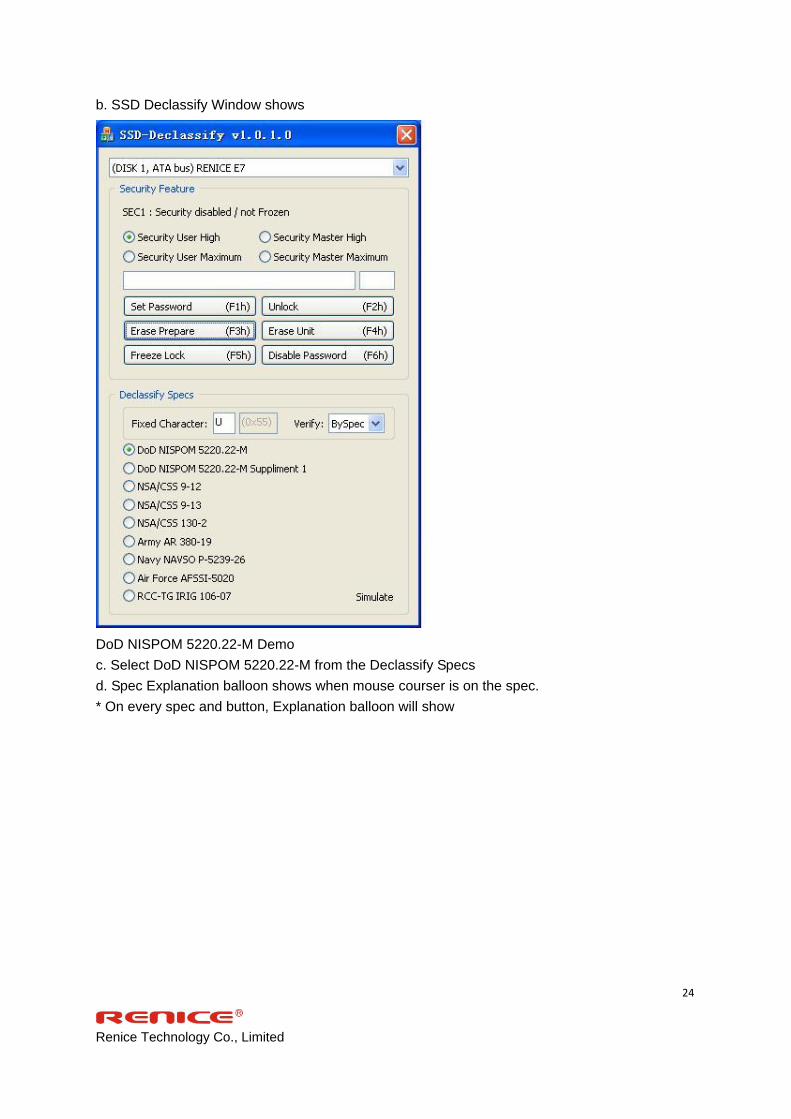
b. SSD Declassify Window shows
DoD NISPOM 5220.22-M Demo
c. Select DoD NISPOM 5220.22-M from the Declassify Specs
d. Spec Explanation balloon shows when mouse courser is on the spec.
* On every spec and button, Explanation balloon will show

Renice Technology Co., Limited
25
Renice Technology Co., Limited
26
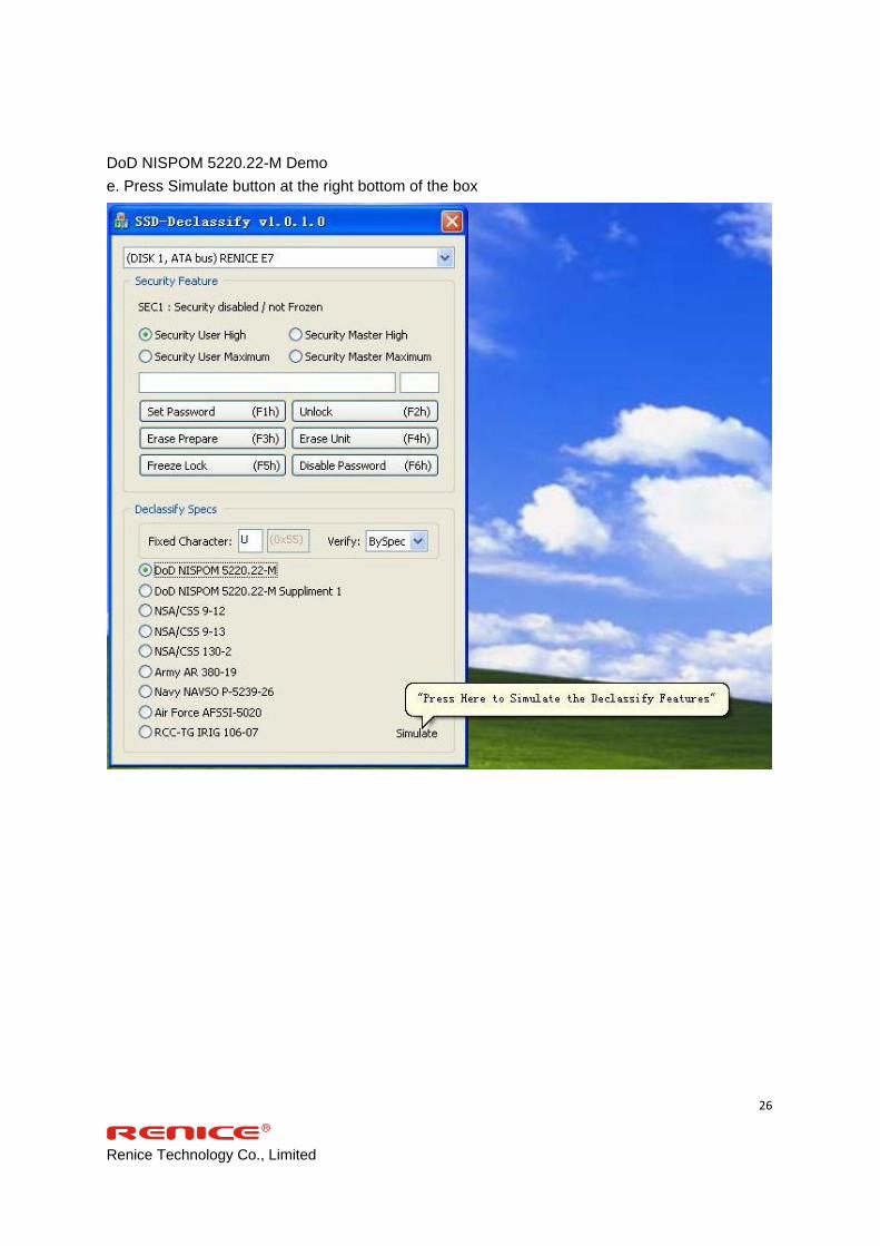
DoD NISPOM 5220.22-M Demo
e. Press Simulate button at the right bottom of the box

Renice Technology Co., Limited
27
DoD NISPOM 5220.22-M Demo
f. Simulate Declassify Feature window will pop-up

Renice Technology Co., Limited
28
DoD NISPOM 5220.22-M Demo
g. If one wants to execute the declassifying procedure one by one
h. DoD NISPOM 5220.22-
* Each will always followed by F3h(prepare) and then F4h(Erase)

Renice Technology Co., Limited
29
DoD NISPOM 5220.22-M Demo
i. Click ‘Step by Step’
j. First procedure will start

Renice Technology Co., Limited
30
DoD NISPOM 5220.22-M Demo
k.When first procedure is done,the window will show it’s done and execution time.

Renice Technology Co., Limited
31
DoD NISPOM 5220.22-M Demo
I.Click ‘Step by Step’
m. Second procedure will start with its operation details

Renice Technology Co., Limited
32
DoD NISPOM 5220.22-M Demo
n.When the procedure is done,the window will show it’s done and execution time

Renice Technology Co., Limited
33
DoD NISPOM 5220.22-M Demo
O.Click ‘Step by Step’
p. Third procedure will start with its operation details
Renice Technology Co., Limited
34
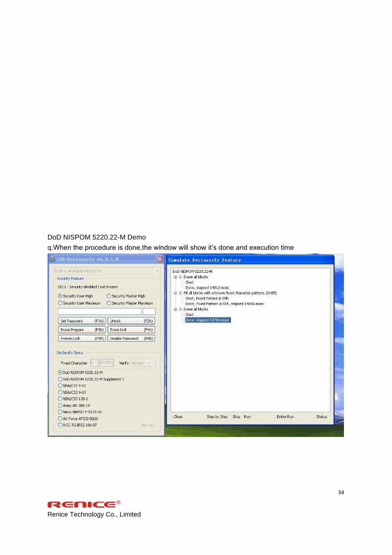
DoD NISPOM 5220.22-M Demo
q.When the procedure is done,the window will show it’s done and execution time

Renice Technology Co., Limited
35
DoD NISPOM 5220.22-M Demo
r. If one wants to execute the declassifying procedure at once
Click’Entire Run’button.
s. DoD NISPOM 5220.22-
* All 3 steps will be executed by sending F3h(prepare) and F4h(Erase) command just once.
* Each procedure is constructed with internal script and a host can send a configuration of script
to meet various declassify specifications

Renice Technology Co., Limited
36
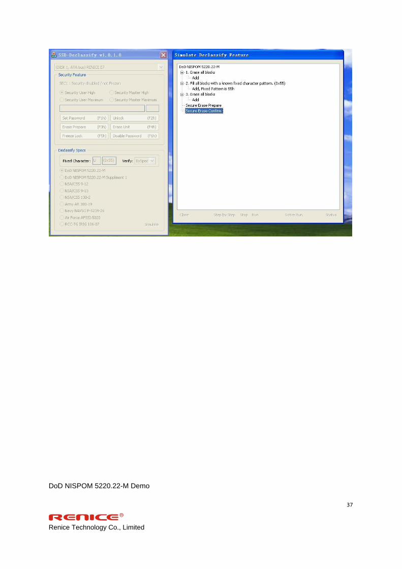
DoD NISPOM 5220.22-M Demo
t. Click’Entire Run’
u. The entire procedure will start with its operation details
Renice Technology Co., Limited
37
DoD NISPOM 5220.22-M Demo

Renice Technology Co., Limited
38
v. When the procedure is done,the window will show it’s done and execution time
Renice Technology Co., Limited
39
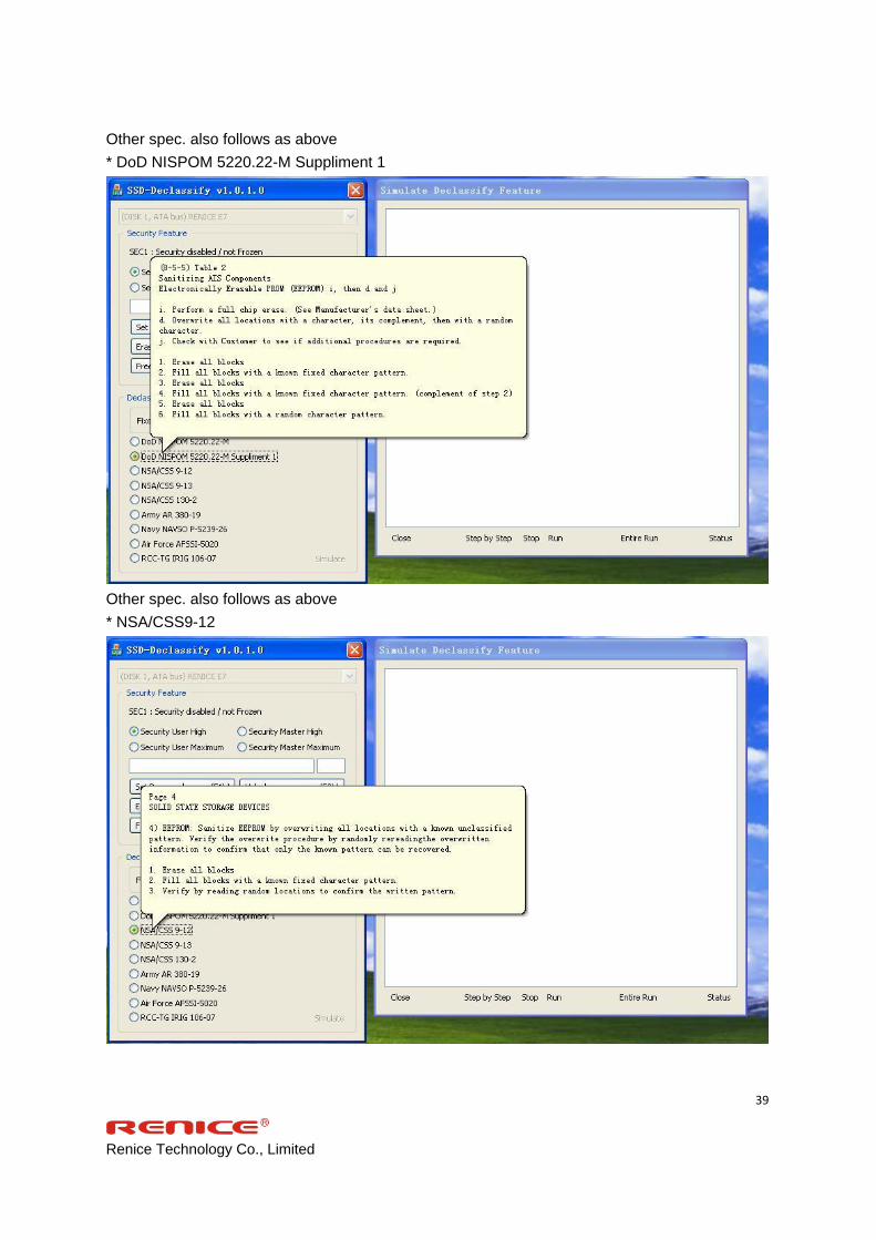
Other spec. also follows as above
* DoD NISPOM 5220.22-M Suppliment 1
Other spec. also follows as above
* NSA/CSS9-12

Renice Technology Co., Limited
40
Other spec. also follows as above
* NSA/CSS9 130-2
Other spec. also follows as above
* Army AR380-19

Renice Technology Co., Limited
41
Other spec. also follows as above
* Navy NAVSO P-5239-26

Renice Technology Co., Limited
42
Other spec. also follows as above
* Air Force AFSSI-5020
Other spec. also follows as above
* RCC-TG IRIG 106-07

Renice Technology Co., Limited
43
Eastwho Secure Erase Function is compatible with ATA Security Feature
Can test ATA Security Feature with this demo kit

Renice Technology Co., Limited
44
Eastwho Secure Erase Function is compatible with ATA Security Feature
Can test ATA Security Feature with this demo kit
Eastwho Secure Erase Function is compatible with ATA Security Feature
Can test ATA Security Feature with this demo kit

Renice Technology Co., Limited
45
Eastwho Secure Erase Function is compatible with ATA Security Feature
Can test ATA Security Feature with this demo kit