repair and service manual for fairey/superwinch overdrives ... repair and service manual.pdf ·...
TRANSCRIPT

Copyright by Ulrico Becker
REPAIR AND SERVICE MANUAL FOR
FAIREY/SUPERWINCH OVERDRIVES FOR
LAND ROVER SERIES VEHICLES To service products that were sold by:

Copyright by Ulrico Becker
2nd edition
OVERDRIVE
MANUAL
SERIES
vehicles for
– 1 –
Contents
1. Overview
2. Schematic drawing and references
3. Parts description
4. Schematic operations of an overdrive unit
5. Disassembly
6. Preparation for removal of the main components
7. Removal of the main shaft
8. Removal of output gear shaft , lay gear and lay shaft
9. Disassembly, inspection and assembly of the synchro hub
10. Inspection of components
11. References of bearings and seals
12. Some sources for spare parts
13. Pre-assembly of housing, laygear, main shaft and output gear
shaft before final assembly
14. Final assembly
15. Assembly to the vehicle
Copyright by Ulrico Becker
2nd edition
OVERDRIVE
MANUAL
SERIES
vehicles for
– 2 –
Overview
This manual covers disassembly, inspection and assembly operations for Fairey
Overdrive Units to fit Land Rover Series I – III vehicles. Fairey OD units were later
manufactured by Superwinch following the same design. Today overdrives are sold
and manufactured by RoversDownSouth.
It does not cover the clutch sleeve unit.
References given for bearings and seals are according to international standard and
should allow the user to source them at any bearing or industrial supply dealer.
No special tooling is required apart from circlip pliers for external circlips. A vernier
caliper and a pen to mark metallic surfaces can prove useful. Access to a press is
helpful but not vital if a large vice is available. A dentist’s mirror and a small torch light
may also prove useful.
This manual has been compiled with utmost care. However, it is not an official
manual, but has been written out of personal interest with the rebuilding of Land
Rover Series vehicles. The author is a mechanical engineer who has been involved in
the automotive industry for many years.
All explanations given have been verified on the author’s overdrive units and are
intended to give a guide line to an easy rebuild of the unit. Typing mistakes have
been eliminated where found. However, no responsibility for any problems
encountered during operations can be the liability of the author. The manual is
intended as a guide line only and requires some knowledge by any user to properly
execute the rebuild.
Many thanks to Moci, who with his six years of age proved himself to be a reliable
partner in holding components for taking pictures and an unerring hunter when
looking for springs that had jumped. And to John Denham in correcting my english
and giving a lot of advice regarding technical precision and clarity and Rik Thiel who
provided the schematic drawing on overdrive operation modes. Both live in Australia.
Copyright by Ulrico Becker
2nd edition
OVERDRIVE
MANUAL
SERIES
vehicles for
– 3 –
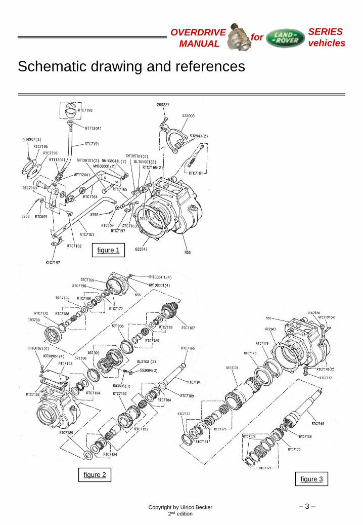
Schematic drawing and references
figure 1
figure 2 figure 3

Copyright by Ulrico Becker
2nd edition
OVERDRIVE
MANUAL
SERIES
vehicles for
– 4 –
Parts description

Copyright by Ulrico Becker
2nd edition
OVERDRIVE
MANUAL
SERIES
vehicles for
– 5 –
Schematic operations of an overdrive unit
In position “out” the synchro hub is in its forward position and couples the blue
mainshaft directly to the orange output gearshaft. The laygear idles.
In position “in” the synchro hub is in its rear position and couples the blue mainshaft to
the green input gear. Torque is then transmitted via the olive laygear to the orange
output gearshaft.
Mainshaft
Output gearshaft
Laygear
Inputgear Synchro hub
Picture compiled by Rik Thiel
rea
r f
orw
ard

Copyright by Ulrico Becker
2nd edition
OVERDRIVE
MANUAL
SERIES
vehicles for
– 6 –
Preparation for removal of main components
Removal from the vehicle
1. Disconnect the link rod (RTC7161, fig. 1) from the selector shaft.
2. Remove the six nuts holding the OD in place and pull it out of the gearbox. Two nuts can only be completely removed once the unit is pulled back by about 10mm.
3. Drain the oil by removing the drain plug (RTC7177, fig. 3). The unit contains 0.4l of EP90 type oil. It is advisable to drain the oil through a fine meshed strainer to retain any metallic components for analysis.
Preparation for disassembly of the main components
1. Wash and clean the unit from the outside to avoid mud and particles to contaminate your working surface.
2. Remove the top cover plate (RTC7183, fig. 2).
3. Remove the detent grub screws (RTC7181, fig. 1), starting with the one on the top side. This serves to limit maximum travel of the selector shaft. Care needs to be taken with the one on the bottom side. It compresses the selector spring to press a ball onto the selector shaft. This fits into three recesses on the shaft, marking the positions “low”, “neutral” and “high”.

Copyright by Ulrico Becker
2nd edition
OVERDRIVE
MANUAL
SERIES
vehicles for
– 7 –
Preparation for removal of main components
4. Remove the sealing plate for the
selector shaft (RTC7167, fig. 1)
5. Remove the pinch bolt (255227, fig. 1)
6. Pull the selector shaft out of the housing
and carefully remove the selector fork
(522003, fig. 1) together with the swivel
pads (532943, fig. 1). Should they fall
into the housing during the procedure
retrieve them once the main and lay
shaft have been removed.
7. Remove the rear cover plate. It is
recommended to have the unit in a
vertical position for the next operations.
Place it on the bench, resting on the
output gearshaft, and support it by
suitably sized pieces of timber.

Copyright by Ulrico Becker
2nd edition
OVERDRIVE
MANUAL
SERIES
vehicles for
– 8 –
Removal of the main shaft
Removal of the main shaft
1. Remove circlip and collar (RTC7172 and
RTC7190, fig. 2)
2. Remove the next circlip, then the axial
bearing group (RTC7186, fig. 2)
consisting of two hardened races and
the bearing cage, and finally the pack of
shims (RTC7189, fig. 2). These serve to
adjust the end float of the whole main-
/outputshaft assembly.
3. Remove the input gear assembly
(RTC7187, fig. 2) together with the ball
bearing (ID3790, fig. 2). It should come
out easily as it is designed to be a loose
fit. Should problems be experienced
however, warming the housing with a
blow torch will normally free it.
If no such tool at hand, leave it in until
the output gear shaft has been taken
out, then tap it out from inside the
housing. Take care not to lose the
needle bearing and the two distance
sleeves inside (RTC7188, fig. 2)

Copyright by Ulrico Becker
2nd edition
OVERDRIVE
MANUAL
SERIES
vehicles for
– 9 –
Removal of the main shaft
4. Remove the second axial needle
bearing group and the radial needle
bearing (RTC7186 and RTC7185, fig.
2). Take the synchromesh cone out
(571936, fig. 2)
The inner race (RTC7185, fig. 2) is a
light press fit on the mainshaft and holds
the mainshaft in its position inside the
output gear shaft.
5. With a soft mallet tap the mainshaft
forward until the inner race is freed. As
the main shaft will drop free it is
important to have the OD unit in vertical
position and place a piece of timber
underneath to soften its fall (5 cm only).
6. Lift the overdrive unit to free the
mainshaft. Be careful not to hit the
synchro hub assembly. If this falls out it
may spring apart and the three balls and
springs between inner and outer hub
may get lost.
The main shaft disassembly is now
completed.
Copyright by Ulrico Becker
2nd edition
OVERDRIVE
MANUAL
SERIES
vehicles for
– 10 –
Removal of output gear shaft, lay gear and lay
shaft
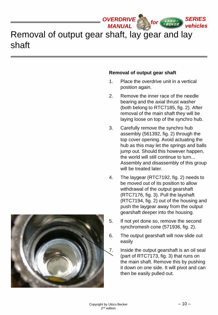
Removal of output gear shaft
1. Place the overdrive unit in a vertical
position again.
2. Remove the inner race of the needle
bearing and the axial thrust washer
(both belong to RTC7185, fig. 2). After
removal of the main shaft they will be
laying loose on top of the synchro hub.
3. Carefully remove the synchro hub
assembly (561392, fig. 2) through the
top cover opening. Avoid actuating the
hub as this may let the springs and balls
jump out. Should this however happen,
the world will still continue to turn...
Assembly and disassembly of this group
will be treated later.
4. The laygear (RTC7192, fig. 2) needs to
be moved out of its position to allow
withdrawal of the output gearshaft
(RTC7176, fig. 3). Pull the layshaft
(RTC7194, fig. 2) out of the housing and
push the laygear away from the output
gearshaft deeper into the housing.
5. If not yet done so, remove the second
synchromesh cone (571936, fig. 2).
6. The output gearshaft will now slide out
easily
7. Inside the output gearshaft is an oil seal
(part of RTC7173, fig. 3) that runs on
the main shaft. Remove this by pushing
it down on one side. It will pivot and can
then be easily pulled out.

Copyright by Ulrico Becker
2nd edition
OVERDRIVE
MANUAL
SERIES
vehicles for
– 11 –
Removal of output gear shaft, lay gear and lay
shaft
1. Remove the laygear, the axial and radial
needle bearings and the shims to
control the end float (RTC7189,
RTC7184, RTC7193 and RTC7192, all
fig. 2)
2. Tap the oil seal between output gear
shaft and housing (part of RTC7173,
fig. 3) and the roller bearing (RTC7179,
fig. 3) out using a suitable drift. Carefully
tap the bearing only. This will then also
push the seal out.
3. The disassembly of the unit is now
completed.

Copyright by Ulrico Becker
2nd edition
OVERDRIVE
MANUAL
SERIES
vehicles for
– 12 –
Disassembly, inspection and assembly of the
synchro hub
1. The unit can be easily separated by just
pushing the inner or outer hub beyond
the holding point of the balls. Just hold it
with both hands and push the inner hub
out with your thumbs. It is best done
inside a cardboard box covered with a
towel to avoid springs and balls to fly
away. Wash all components.
2. The teeth of the outer hub show marks
similar to wear marks. They are ma-
chined on purpose to prevent the gears
from jumping out when under load.
The splines of the inner hub did not
show any marks on the unit assembled
here.
It is unlikely for there to be strong wear
marks on the splines of the bore and the
corresponding splines on the main shaft.
If there are, some play can be tolerated.
Too much play may affect the gear
selection.
3. The teeth should be sharp and only a
little rounded. The unit shown here
shows some wear but will still work well
for many miles. Their function is to guide
the outer hub when gliding over the
synchromesh cone onto the teeth of
output shaft or input gear. If the teeth
are well rounded, gear selection will be
more difficult. It is best to replace the
hub then.
The same criteria are valid for the teeth
of the synchromesh cones and the teeth
on the output gearshaft

Copyright by Ulrico Becker
2nd edition
OVERDRIVE
MANUAL
SERIES
vehicles for
– 13 –
Disassembly, inspection and assembly of the
synchro hub
4. If all components are found satisfactory,
prepare assembly. It is advised to
assemble inner and outer hub in a
similar radial position against each other
as they were found in. These three
possible positions are defined by the
marks left by the balls. Place inner and
outer hub into each other and verify that
the parts can slide easily against each
other (Both parts should be oily when
doing this to avoid binding. This could
happen if they are completely dry
although there is no problem). Mark the
selected position.
5. The sliding blocks (553084, fig. 2) are
not symmetrical. The curved side has to
show outwards.

Copyright by Ulrico Becker
2nd edition
OVERDRIVE
MANUAL
SERIES
vehicles for
– 14 –
Disassembly, inspection and assembly of the
synchro hub
6. No information could be obtained on the
nominal free length of the springs
(503805, fig. 2). If they were not broken
or twisted the author has used them
again. When assembled they should
firmly hold the outer hub in a neutral
position. Their reason for being is to
prevent the hub from wandering and
wearing down the swivel pads. The hub
could then inadvertently crash into input
gear or output gearshaft.
7. The assembly of the springs, sliding
blocks and balls is less complicated
than one would expect. Take only one
set and wedge the spring in between
inner and outer hub as shown. Then
place the ball onto the spring and press
it with your thumb nail in its position
under the outer hub. Alternatively a fine
blade can be used. To repeat it for the
next set, move the inner hub out as far
as possible without releasing the set
assembled previously and tilt it. Even if
this can be done only by a small amount
it will be sufficient to allow assembly of
the second set in the manner described
above. The third set obviously requires
more force to press the ball under the
outer hub because the amount of tilt is
now very much reduced with two sets
already in place.
It is strongly recommended to do this in
a protected environment (large card-
board box or room where everything can
be found again [If you have one, but
who has one?]) because the springs fly
far when they fly.
Copyright by Ulrico Becker
2nd edition
OVERDRIVE
MANUAL
SERIES
vehicles for
– 15 –
Inspection of components
Inspection of components should be done taking into account the possibility of
replacing worn or damaged parts. Gear boxes can still have a long life in them even if
gears and other parts are quite worn.
Components with chipped teeth should be replaced. Even if the tooth isn’t completely
gone yet this is an indicator to a problem that will only become worse if not cured.
Gears with signs of pitting may still make many miles but will be noisy.
If the effort has been spent to dismantle an overdrive unit and the history of this unit is
unknown all bearings and seals should be replaced.
If seals have left a groove on the shaft, go with housing and shaft to a specialist dealer
and look for either a seal with a different position of the lip or for shims that will move
the seal’s lip onto another part of the shaft. Speedy sleeves may also be an option.
The races for axial needle roller bearings (components starting with AS in the table on
page 17) have to be replaced if any signs of wear apart from shiny surfaces can be
noticed.
Bearing surfaces with signs of wear should be replaced. Needle bearings will not last
long if running on pitted or otherwise damaged surfaces. If this surface is on a costly
component like the output gear shaft the whole shaft should be replaced. Alternatively,
on bores and shafts, a machine shop can shrink a hardened bush into or onto these
components which is then ground to size and surface requirements. This is however
only viable for people with a “close” contact to such a facility. Otherwise this can be
more expensive than replacing the part.
Synchromesh cones (571936, fig. 2) show an array of elevated lines on the inside.
These serve to build oil pockets which help preventing the brass cone to stick on the
steel cone on gears or shafts and maintain controlled friction conditions which are
essential for smooth gear changes. If these lines are worn to the degree of nearly
having disappeared the cone has to be replaced.
The swivel pads (532943, fig. 1) should present an even wear pattern and show no
strongly asymmetrical shape. If they have too much play in the fork (522003, fig. 1) it
is advisable to replace them.

Copyright by Ulrico Becker
2nd edition
OVERDRIVE
MANUAL
SERIES
vehicles for
– 16 –
References of bearings and seals
Apart from one all bearings and seals conform to common industrial standards and are
available via specialist dealers or industrial supply companies. The table given below is a
compilation of all bearings and seals but the needle bearing of the clutch sleeve. This is to
assist local sourcing of these components.
Copyright by Ulrico Becker
2nd edition
OVERDRIVE
MANUAL
SERIES
vehicles for
– 17 –
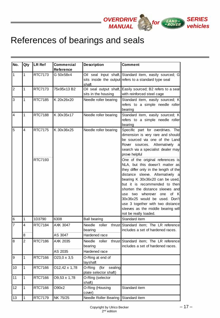
References of bearings and seals
No. Qty LR Ref Commercial
Reference
Description Comment
1 1 RTC7173 G 50x58x4 Oil seal Input shaft,
sits inside the output
shaft
Standard item, easily sourced; G
refers to a standard type seal
2 1 RTC7173 75x95x13 B2 Oil seal output shaft,
sits in the housing
Easily sourced; B2 refers to a seal
with reinforced steel cage
3 1 RTC7185 K 20x26x20 Needle roller bearing Standard item, easily sourced; K
refers to a simple needle roller
bearing
4 1 RTC7188 K 30x35x17 Needle roller bearing Standard item, easily sourced; K
refers to a simple needle roller
bearing
RTC7175 Specific part for overdrives. The
dimension is very rare and should
be sourced via one of the Land
Rover sources. Alternatively a
search via a specialist dealer may
prove helpful
RTC7193 One of the original references is
NLA, but this doesn’t matter as
they differ only in the length of the
distance sleeve. Alternatively a
bearing K 30x36x20 can be used,
but it is recommended to then
shorten the distance sleeves and
use two wherever one of K
30x36x25 would be used. Don’t
use 3 together with two distance
sleeves as the middle bearing will
not be really loaded.
6 1 1D3790 6308 Ball bearing Standard item
4 AXK 3047 Needle roller thrust
bearing
8 AS 3047 Hardened race
AXK 2035 Needle roller thrust
bearing
AS 2035 Hardened race
9 1 RTC7166 O23,0 x 3,5 O-Ring at end of
layshaft
10 1 RTC7166 O12,42 x 1,78 O-Ring (for sealing
plate selector shaft)
11 1 RTC7166 O9,53 x 1,78 O-Ring (selector
shaft)
12 1 RTC7166 O90x2 O-Ring (Housing
cover)
Standard item
13 1 RTC7179 NK 75/25 Needle Roller Bearing Standard item
5 4 K 30x36x25 Needle roller bearing
7 RTC7184 Standard item; The LR reference
includes a set of hardened races.
8 2 RTC7186 Standard item; The LR reference
includes a set of hardened races.

Copyright by Ulrico Becker
2nd edition
OVERDRIVE
MANUAL
SERIES
vehicles for
– 18 –
Some sources for spare parts
LEGS Shropshire, UK http://www.legs.co.uk
Rovers Down South New Orleans, USA http://www.faireyoverdrive.com
PG Winches Cornwall, UK http://www.winchrepairs.co.uk/
John Craddock Derbyshire, UK http://www.johncraddockltd.co.uk
There may of course be some more, like the specialist gear manufacturers or the
companies that produce synchromesh cones for the automotive industry. Above addresses
however should provide some first assistance when looking for replacement parts. The
whole range only seems available from Rovers Down South. It is understood that they have
bought the rights of Superwinch for these products. During the rebuild of the unit shown
they have been very helpful.

Copyright by Ulrico Becker
2nd edition
OVERDRIVE
MANUAL
SERIES
vehicles for
– 19 –
Pre-assembly of housing, laygear, mainshaft and
output gearshaft before final assembly
1. The mainshaft is an ideal tool to position
the oil seal inside the output gear shaft.
Mark it at about 70 mm from the input
end. High precision is not required for
positioning of the oil seal. Basically all of
the shiny circumference can serve as a
running surface for the seals’ lip.
The author has been informed that
some OD units have a slight groove
machined on the inside of the output
gear shaft to locate the seal. This unit
here however did not show this groove.
2. Lubricate the inside of the output gear-
shaft to allow the seal to slide easily into
its position. Grease the lip of the seal to
avoid it running dry when putting the unit
back into operation.
Present the seal to the output gear shaft
and push it in with your hand. Turn it
into horizontal position.
3. Use the main shaft as a “ram” and push
the seal into the output gear shaft until
the mark is level with it’s top or the seal
settles inside the groove.

Copyright by Ulrico Becker
2nd edition
OVERDRIVE
MANUAL
SERIES
vehicles for
– 20 –
Pre-assembly of housing, laygear, main shaft and
output gear shaft before final assembly
4. Slide the bearing race and the bearing
(RTC7174, fig. 3) onto the main shaft
and lubricate it with EP 90.
5. Take care to place the lower race (the
thicker one) in its correct position. It is
chamfered on one side and this chamfer
needs to face towards the input end of
the main shaft.
6. Slide the two radial bearings and the
distance sleeve (RTC7175, fig. 3) over
the main shaft and lubricate the
bearings with EP 90.
Place the main shaft on a round support
of at least 50 mm height and smaller in
diameter than the main shaft. This is
needed to allow the output gearshaft to
be placed on the mainshaft.

Copyright by Ulrico Becker
2nd edition
OVERDRIVE
MANUAL
SERIES
vehicles for
– 21 –
Pre-assembly of housing, laygear, main shaft and
output gear shaft before final assembly
7. Slide the output gearshaft over the main
shaft. Take care not to damage the seal
inside the output gearshaft.
8. Drip some more EP 90 onto the radial
needle roller bearings.

Copyright by Ulrico Becker
2nd edition
OVERDRIVE
MANUAL
SERIES
vehicles for
– 22 –
Pre-assembly of housing, laygear, main shaft and
output gear shaft before final assembly
9. Place the needle roller bearing and the
races (RTC7184, fig. 2)into the recess in
the output gear shaft. Drip some oil onto
the inner diameter of the synchromesh
cone and position it onto the output gear
shaft.
10. Place the roller bearing (RTC7173, fig.
3) on top of the housing and carefully
tap it home. This can be done with a
hammer and a suitable drift, tapping
always on opposite sides and after a
few taps changing between the
positions 12 and 6 and 3 and 9 o’clock.
Lubricate the bearing seat before
presenting the bearing.
11. Do the same then with the oil seal (part
of RTC7173, fig. 3), taking care not to
deform the seal during the tapping
home.

Copyright by Ulrico Becker
2nd edition
OVERDRIVE
MANUAL
SERIES
vehicles for
– 23 –
Pre-assembly of housing, laygear, main shaft and
output gear shaft before final assembly
12. Lubricate the bearing and grease the
seal.
13. Put the housing into a vertical position
and insert the laygear. Lubricate the
bearings. Slide the bearing packages
(RTC7184, fig. 2) in as shown, starting
with the bottom one. The shims
(RTC7189, fig. 2) coming out from
disassembly should be used again.
Their purpose is to limit the end float of
the lay gear and they have been
selected according to interference of
laygear and housing tolerances.
Bearings and races are standardized
and replacements will be fully
interchangeable. In the unit shown
shims were found at the front end of the
lay gear and will be inserted there again.
14. Put a drift, chisel or comparable tool into
the lay gear bore to avoid shims,
bearings and races to move beyond the
bore diameter. Move bearings, races
and shims to the inside, away from the
gears’ teeth.
15. Mainshaft / output gearshaft assembly
and housing are now ready to be joined.

Copyright by Ulrico Becker
2nd edition
OVERDRIVE
MANUAL
SERIES
vehicles for
– 24 –
Final assembly
1. Select two suitable supports for the
housing which will keep it roughly in its
definite position after being joined with
the shaft assembly.
2. Carefully slide the housing over the
mainshaft / output gearshaft assembly
until it rests on the supports.
Copyright by Ulrico Becker
2nd edition
OVERDRIVE
MANUAL
SERIES
vehicles for
– 25 –
Final assembly
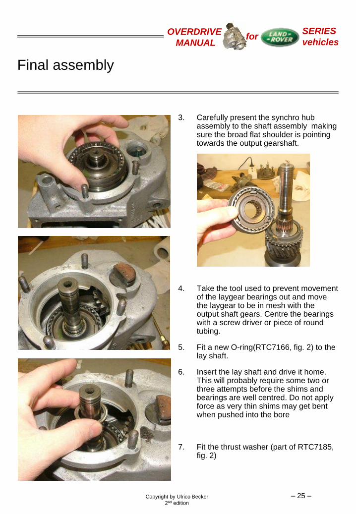
3. Carefully present the synchro hub assembly to the shaft assembly making sure the broad flat shoulder is pointing towards the output gearshaft.
4. Take the tool used to prevent movement of the laygear bearings out and move the laygear to be in mesh with the output shaft gears. Centre the bearings with a screw driver or piece of round tubing.
5. Fit a new O-ring(RTC7166, fig. 2) to the lay shaft.
6. Insert the lay shaft and drive it home. This will probably require some two or three attempts before the shims and bearings are well centred. Do not apply force as very thin shims may get bent when pushed into the bore
7. Fit the thrust washer (part of RTC7185, fig. 2)

Copyright by Ulrico Becker
2nd edition
OVERDRIVE
MANUAL
SERIES
vehicles for
– 26 –
Final assembly
8. Lubricate the inner surface of the inner bearing race (part of RTC7185, fig. 2)
9. Slide it over the main shaft
10. Use a suitable drift, in this case a piece of tubing, to drive the race home. It is a light press fit and holds the synchro hub in place on the main shaft. One of the axial bearing races has been used to bridge the gap in diameter between tubing and inner race. It is important for the output gear shaft to be resting only on the axial bearings on the main shaft. Make sure this is the case and the output gear shaft is not being supported by anything else.
Copyright by Ulrico Becker
2nd edition
OVERDRIVE
MANUAL
SERIES
vehicles for
– 27 –
Final assembly
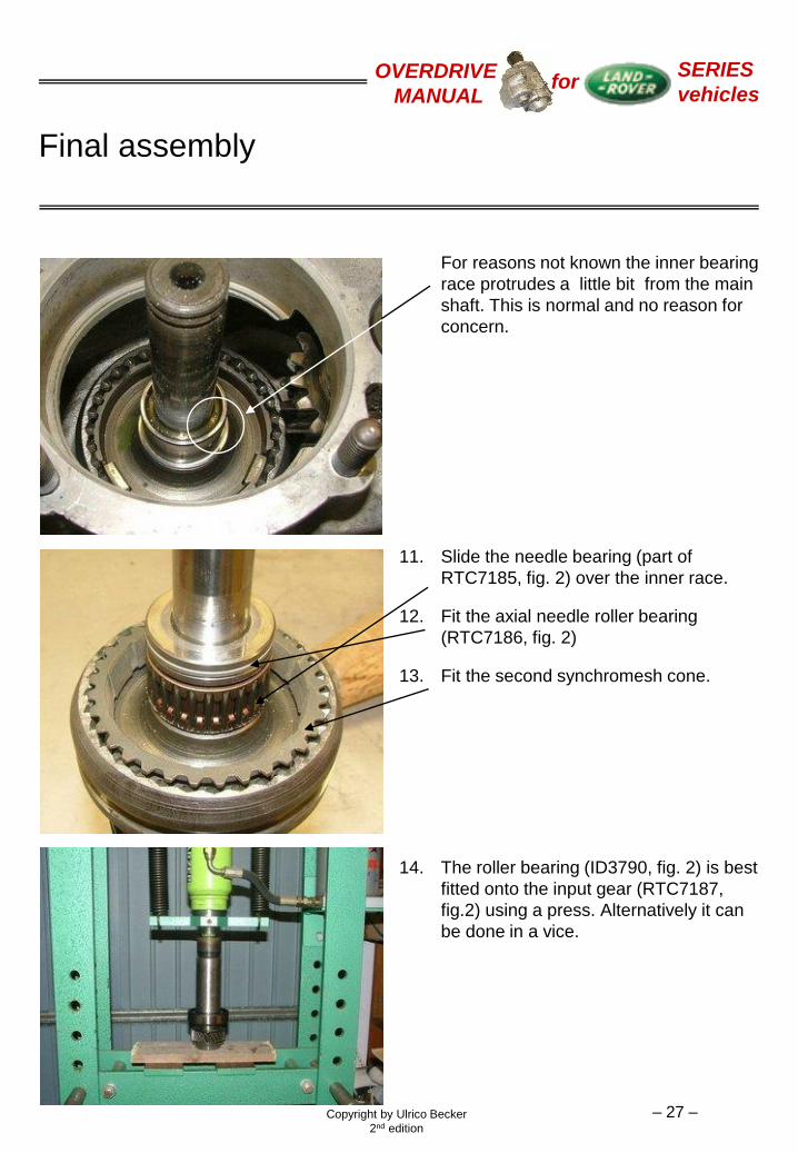
For reasons not known the inner bearing
race protrudes a little bit from the main
shaft. This is normal and no reason for
concern.
11. Slide the needle bearing (part of
RTC7185, fig. 2) over the inner race.
12. Fit the axial needle roller bearing
(RTC7186, fig. 2)
13. Fit the second synchromesh cone.
14. The roller bearing (ID3790, fig. 2) is best
fitted onto the input gear (RTC7187,
fig.2) using a press. Alternatively it can
be done in a vice.

Copyright by Ulrico Becker
2nd edition
OVERDRIVE
MANUAL
SERIES
vehicles for
– 28 –
Final assembly
15. Fit the large circlip (RTC7172, fig. 2) to
secure the roller bearing
16. Slide the input gear assembly over the
main shaft and press it into the housing.
As it is a loose fit it will slide in easily.
No problems should be encountered
bringing it into mesh with the laygear.
17. Insert the first distance sleeve, then the
radial needle roller bearing and last the
second distance sleeve (all RTC7188,
fig. 2)

Copyright by Ulrico Becker
2nd edition
OVERDRIVE
MANUAL
SERIES
vehicles for
– 29 –
Final assembly
18. Fit the shims (RTC7189, fig. 2) and then the second axial bearing group (RTC7186, fig. 2). The shims control the end float of the main shaft. This is only measurable once the rear cover has been bolted to the housing. It can be checked by rocking the output gearshaft forwards and backwards. The output gearshaft is held on the mainshaft via the inner racing (part of RTC7185, fig. 2) and shows no end float. The main shaft requires a definite end float. Its amount however is not critical as long as it is clearly identifiable. The unit shown has an end float of around 1,5 mm. Rovers Down South say that all end floats in the unit should be between 0,05 and 0,1 mm. None of the authors units however has ever shown such a small value.
19. Fit the first circlip (part of RTC7172, fig. 2). Note that the two circlips are of dif-ferent thickness. They must not be inter-changed as the thicker one has to with-stand the unit’s axial operating loads
20. Fit the collar (RTC7190, fig. 2) and the second circlip.
Copyright by Ulrico Becker
2nd edition
OVERDRIVE
MANUAL
SERIES
vehicles for
– 30 –
Final assembly
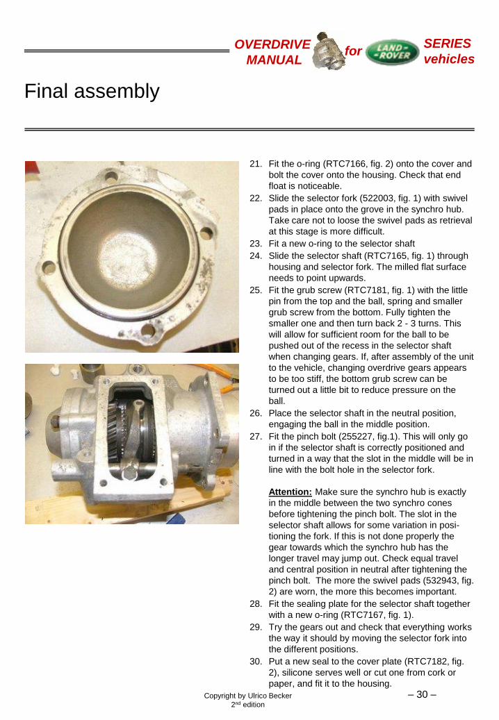
21. Fit the o-ring (RTC7166, fig. 2) onto the cover and
bolt the cover onto the housing. Check that end
float is noticeable.
22. Slide the selector fork (522003, fig. 1) with swivel
pads in place onto the grove in the synchro hub.
Take care not to loose the swivel pads as retrieval
at this stage is more difficult.
23. Fit a new o-ring to the selector shaft
24. Slide the selector shaft (RTC7165, fig. 1) through
housing and selector fork. The milled flat surface
needs to point upwards.
25. Fit the grub screw (RTC7181, fig. 1) with the little
pin from the top and the ball, spring and smaller
grub screw from the bottom. Fully tighten the
smaller one and then turn back 2 - 3 turns. This
will allow for sufficient room for the ball to be
pushed out of the recess in the selector shaft
when changing gears. If, after assembly of the unit
to the vehicle, changing overdrive gears appears
to be too stiff, the bottom grub screw can be
turned out a little bit to reduce pressure on the
ball.
26. Place the selector shaft in the neutral position,
engaging the ball in the middle position.
27. Fit the pinch bolt (255227, fig.1). This will only go
in if the selector shaft is correctly positioned and
turned in a way that the slot in the middle will be in
line with the bolt hole in the selector fork.
Attention: Make sure the synchro hub is exactly
in the middle between the two synchro cones
before tightening the pinch bolt. The slot in the
selector shaft allows for some variation in posi-
tioning the fork. If this is not done properly the
gear towards which the synchro hub has the
longer travel may jump out. Check equal travel
and central position in neutral after tightening the
pinch bolt. The more the swivel pads (532943, fig.
2) are worn, the more this becomes important.
28. Fit the sealing plate for the selector shaft together
with a new o-ring (RTC7167, fig. 1).
29. Try the gears out and check that everything works
the way it should by moving the selector fork into
the different positions.
30. Put a new seal to the cover plate (RTC7182, fig.
2), silicone serves well or cut one from cork or
paper, and fit it to the housing.

Copyright by Ulrico Becker
2nd edition
OVERDRIVE
MANUAL
SERIES
vehicles for
– 31 –
Assembly to the vehicle
1. Fill the unit with 0.4 litres of EP90
2. Turn the output gear shaft to allow the oil to reach all areas.
3. Use a special grease to lubricate the rectangular splines inside the main shaft. This grease should maintain a constant viscosity over a large temperature range. MoS2 or something similar will do a good job. Bearing suppliers stock a range of suitable greases.
4. To assemble the overdrive unit back to the vehicle, unless you have a comfortable way to reach it from underneath, the safest way is as follows:
a) Place the unit on some sort of support (box, reversed bucket, jack etc.) and push it under the vehicle roughly to the position where it is fitted and oriented in the way it will be inserted.
b) From above, after lifting the seat box lid, take a rope or sling and sling it once around the output gear shaft.
c) Coming from the right side of the vehicle, lift the unit with your left hand and pull the sling up with your right hand. The unit can thus be easily presented to the gearbox.
Laying under the vehicle, trying to lift it with both hands requires some strength and only gives bad leverage. The risk of letting the unit fall onto whatever or whoever is underneath it must not be disregarded.
5. Slide the unit into the gearbox. It should go in nearly all the way, but sometimes getting it into mesh does not work at first trial. There are two options to achieve this: pull the unit out again until you can turn the output gear shaft by hand. Turn it a little bit and try again. Alternatively jack the vehicle up at the rear and turn the gears moving the hand brake drum. The main gearbox must be in neutral. The overdrive can be pushed in over the last 10 mm by tightening the six nuts. Note that two of the nuts can only be started, before the unit is right in. Do not forget to fit the clip for the speedo cable under one of the two top nuts. Sometimes the teeth of the main shaft do not slide over the corresponding teeth of the drive dog and prevent the unit to be pushed in the last 10mm. In these cases put the transferbox into neutral and the gearbox in third or fourth gear. Crank the engine with the starter motor for one or two seconds and try again. Repeat this procedure until the overdrive slides in or can be pulled in by tightening the nuts.
6. Tighten the nuts and reconnect the lever linkage