repair and strengthening of r.c flat slab connection with
TRANSCRIPT

_____________________________________________________________________________________________________ *Corresponding author: E-mail: [email protected];
Advances in Research 8(3): 1-22, 2016; Article no.AIR.30352
ISSN: 2348-0394, NLM ID: 101666096
SCIENCEDOMAIN international www.sciencedomain.org
Repair and Strengthening of R.C Flat Slab Connection with Edge Columns against
Punching Shear
K. M. El-Sayed1, N. N. Khalil1 and M. I. Omar1*
1Department of Civil Engineering, Benha Faculty of Engineering, Benha University, Egypt.
Authors’ contributions
This work was carried out in collaboration between all authors. All authors read and approved the
final manuscript.
Article Information
DOI: 10.9734/AIR/2016/30352 Editor(s):
(1) P. V. Nidheesh, Cleaner Technology and Modelling Division, CSIR- National Environmental Engineering Research Institute, Nagpur, India.
Reviewers: (1) Md. Akter Hosen, University of Malaya, Kuala Lumpur, Malaysia.
(2) Hamdy Mohy-El-Din Afefy, Tanta University, Egypt. (3) Islam Ezz El, Tanta University, Egypt.
Complete Peer review History: http://www.sciencedomain.org/review-history/17229
Received 4th November 2016 Accepted 8
th December 2016
Published 13th
December 2016
ABSTRACT
Aims: Study the repair and strengthening of the flat slab-edge column connections against punching shear. Study Design: Parametric study is carried out by varying the repair and strengthening number of stirrups rows and the stirrups materials. Methodology: This paper study the effect of using of Fiber Reinforced Polymers (FRP) systems to strengthen and repair the flat slab-edge column connections subjected to punching shear. These systems is an exterior stirrups manufactured from glass, carbon fibers and steel links. Test results of thirteen half-scale specimens reinforced concrete flat slab-edge column connections were prepared to be tested under vertical punching shear load. The experimental plan for this study included one specimen not strengthened nor repaired which used as control specimen. Six specimens strengthened by exterior stirrups manufactured from Carbon Fiber Reinforced Polymer (CFRP), Glass Fiber Reinforced Polymer (GFRP) and steel links, respectively, three specimens strengthened by one row and the another three strengthened by two rows. Six specimens repaired by exterior stirrups manufactured from (CFRP), (GFRP) and steel links, respectively, three
Original Research Article

El-Sayed et al.; AIR, 8(3): 1-22, 2016; Article no.AIR.30352
2
specimens repaired by one row and the another three strengthened by two rows. Also, the experimental ultimate loads were compared to the calculated values according to ACI 440. Results: The test results were the ultimate load, load-deflection relationships, punching shear resistance, relative ductility, flexural stiffness & punching shear angle. Conclusion: The test results illustrated punching shear strength increasing and an increasing in flexural stiffness for the strengthened and the repaired specimens compared to the control one. In addition, the strengthened and the repaired tested specimens illustrated enhancement in relative ductility and increase in angle of punching shear. The calculated ultimate loads based on ACI 440 procedures were below the experimental ones by 32 to 66%.
Keywords: Edge column-flat slab connections; punching shear failure; strengthening and repair; fiber
reinforced polymer.
1. INTRODUCTION This study is very interesting in the structural engineering point of view. While, flat slab now is one of the most common systems in reinforced concrete structures. A flat slab floor system is often the choice when there is a need for more clear head such as multi-storey car parks, libraries and multi-storey buildings where larger spans are also required. It provides architectural flexibility, more clear space, less building height, easier formwork and, consequently shorter construction time. Failures of flat slab structures were reported during construction [1]. Flat slab can be supported by a column capital or a drop panel in order to provide a good resistance to punching shear around the column. However, in some cases column capitals and drop panels cannot be used for architectural reasons or to save space between the floors. In this case, flat slabs have a major weakness, namely vulnerability to punching shear failure at the column-slab junction column. A serious problem that can arise in flat slab is the brittle punching failure due to transfer of shearing forces. This brittle failure happens with no enough warning [2]. When the slab-column connection is subjected to heavy vertical loading, cracks will occur inside the slab in the vicinity of the column [3]. Then shear stresses due to heavy vertical loading in the region of the slab around the column become too high, a punching failure will occur. The flat slab connection repair very severe issue now. In case of edge connections the distribution of stresses around the column is uneven, therefore the behaviour is non-symmetric [4]. There are mainly three ways to increase the punching shear strength of concrete slabs: 1- Increasing the slab thickness in the vicinity of the column by providing a drop panel or a column head. 2- The strengthening of slab-column connection against punching shear stress by using traditional methods (steel plates,
steel stirrups, steel studs, or increasing concrete dimensions) [5]. 3- An innovative techniques of using FRP enhance the shear performance [6]. G. Ismail [7] presented the results of an experimental program on 26 half-scale two-way reinforced concrete (RC) flat slab specimens with interior column tested under punching shear due to central loading, the research included two specimens with no shear reinforcement as control specimen, three specimens reinforced with internal steel stirrups for comparison, and eighteen specimens strengthened with (GFRP), (CFRP), and steel reinforcement as exterior stirrups. The lasting three specimens repaired using the same materials. The investigated parameters were the stirrups shape of steel and FRP, the stirrups rows number and the distance between the stirrups rows for the used material types. All the techniques used for strengthening of the tested specimens in this research were effective to restore and improve the structural performance in terms of flexural rigidity, initial cracking load and the ultimate carrying capacity. The CFRP intertwined rods gave the best results in comparison with the other material. Makhlouf [8] showed the obtained results from the experimental study of four specimens of half-scale interior flat slab-column connections, which were prepared and tested under punching shear duo to concentrated vertical load. The study included one specimen not strengthened, which was the control specimen, another one strengthened by steel links, another specimen strengthened using exterior (GFRP) stirrups, the last one strengthened using exterior (CFRP) stirrups. All the specimens failed by punching shear. All the materials used in this investigation, to strengthen the slab-column connection, enhanced the shear punching resistance. The using of steel links, (GFRP) and (CFRP) stirrups of the equivalent area improved the ultimate resistance by 60%, 60% & 73%, respectively.

El-Sayed et al.; AIR, 8(3): 1-22, 2016; Article no.AIR.30352
3
2. EXPERIMENTAL INVESTIGATION A test program was carried out to study the potential of using different materials in the repair and strengthening of reinforced concrete flat slab-edge column connections subjected to punching shear. The tested specimens were half-scale models of a typical prototype flat-plate structure. The dimensions of the tested slabs were chosen to cover the area of the negative moment region around the edge column and inside the line of contra-flexure.
2.1 Details of Test Specimens
Thirteen half-scale specimens were prepared, All the specimens have the same dimensions, as shown in Fig. 1, the plane dimensions are 900*900 mm, the thickness is 130 mm with average effective depth 115 mm. Column cross section dimensions are 150*150 mm and its height is 150 mm. Column was casted monolithically at the edge of the slab, with extension upper and lower the slab faces. The tested specimens were designed to be simply supported at the column (point support) and on the opposite side of the slab (line support) with clear spans 750 mm. High tensile steel bars of 12 mm diameters were used as top and bottom reinforcement, the top rft. is 9 12 mm in the transversal direction (parallel to the edge) and 5 12 mm in the longitudinal direction, and the bottom rft. is 12 12 mm in the longitudinal direction and 5 12 mm in the transversal direction. The columns were reinforced with 4 12 vertical high tensile steel bars and 8 mm normal mild steel stirrups every 100 mm. The reinforcement details of the specimen are shown in Fig. 2. The specimens are divided into five groups, as shown in Table 1.
2.2 Preparation of Test Specimens A thirteen wooden moulds were made from plywood sheets achieving the required dimensions. The forms were painted with thin layer of oil before concrete placing. After the steel reinforcement were installed ready mix concrete was mechanically casted for all specimens, then the concrete was vibrated mechanically and the concrete surface was finished. After curing period the specimens were left in the lab atmosphere until test date. After that, the thirteen specimens were divided to five groups as shown in Table 1. Then, the control specimen was loaded till failure and the six specimens in group 4 & 5 were loaded until 75% of the control specimen ultimate load. All the specimens in the four group no. 2, 3, 4 & 5 were drilled to make full penetrated holes of 10 mm diameter at the positions of vertical legs of FRP stirrups or steel links. For strengthening or repair of the column-slab connection of the tested specimens; GFRP, CFRP and steel stirrups of one row and two rows were used as shown in Fig. 3. The interwined FRP closed stirrups were manually manufactured using fiber cross sectional area equivalent to circular cross-section of 8 mm diameter. The FRP wraps were saturated by polyester in case of glass fiber and by epoxy resin (sikadur-330) in case of carbon fiber, and the interwined strands were formed and stitched through holes along the slab thickness as shown in Figs. (4 & 5). 24 hours later, the clearance between GFRP or CFRP stirrups and holes was filled by polyester and epoxy resin, respectively, to ensure good bond between FRP stirrups and concrete. The steel stirrups were locally fabricated using normal tensile steel bars of 8 mm diameter fixed at upper and lower surface by steel nuts supported on steel plates of 5 mm thickness and 40 mm width.
Fig. 1. The specimen dimensions and supports

El-Sayed et al.; AIR, 8(3): 1-22, 2016; Article no.AIR.30352
4
Fig. 2. Full details of the specimen reinforcement
Table 1. The experimental test program Group Specimen
code Specimens description Pre-loading
level Specimen state Number of rows
Strengthening/ Repair elements
No. 1 C Control --- ---------- 0 No. 2 SG1 Strengthening 1 GFRP stirrups 0
SC1 Strengthening 1 CFRP stirrups 0 SS1 Strengthening 1 Steel Links 0
No. 3 SG2 Strengthening 2 GFRP stirrups 0 SC2 Strengthening 2 CFRP stirrups 0 SS2 Strengthening 2 Steel Links 0
No. 4 RG1 Repair 1 GFRP stirrups 0.75Pmax. RC1 Repair 1 CFRP stirrups 0.75Pmax. RS1 Repair 1 Steel Links 0.75Pmax.
No. 5 RG2 Repair 2 GFRP stirrups 0.75Pmax RC2 Repair 2 CFRP stirrups 0.75Pmax RS2 Repair 2 Steel Links 0.75Pmax.
*Pmax. : The ultimate load of the control specimens
3. MATERIAL PROPERTIES
3.1 Concrete
A trial mixes were prepared and a suitable mix was selected which give cubic compressive
strength of 247 kg/cm2 after 28 days, A concrete admixture, commercially called Addicrete BVF was used to improve the workability of fresh concrete. The constituents of concrete mix and its proportions are presented in Table 2.
Table 2. The constituents of concrete mix and its proportions
Concrete compressive strength kg/cm
2
Cement (Kg)/m
3
Crushed dolomite (Kg)/m
3
Sand (Kg) /m
3
Water (Liter)/m
3
Super Plasticizer (Kg) /m3
247 350 1260 630 175 3.5

El-Sayed et al.; AIR, 8(3): 1-22, 2016; Article no.AIR.30352
5
(a) (b)
(c) (d)
(e)
Fig. 3. Details of strengthening and repair systems; one row of steel stirrups (a), one row of FRP stirrups (b), two rows of steel stirrups (c), two rows of FRP stirrups (b) and details of
stirrups types (e)

El-Sayed et al.; AIR, 8(3): 1-22, 2016; Article no.AIR.30352
6
Fig. 4. Manufacturing of GFRP stirrups
Fig. 5. Manufacturing of CFRP stirrups
3.2 FRP The E-glass fibers used to produce the GFRP stirrups were sika wrap Hex-430G, which is a product of sika company, and the used polymer was polyester. High strength carbon fibers manufactured by Sika Company under trade name Sika Wrap Hex-230C and epoxy Sikadur-330 are used to produce the CFRP stirrups. The Mechanical properties of the used fibers are given - according to the manufacturer- in Table 3.
3.3 Steel Links 8 mm diameter normal mild steel (24/35) bars are used to fabricate the steel stirrups for strengthening and repair.
4. TEST PROCEDURE
The tests were carried out in the Reinforced Concrete Laboratory at the Faculty of Engineering in Benha. The loading system
consisted of rigid system of reaction frame, 100 ton maximum capacity, and hydraulic jack, 100 ton maximum capacity, connected to electrical pump which provides oil pressure. The specimens were tested under vertical concentrated load which is distributed to uniform line load acting on the slab upper surface, as shown in Fig. 6. A rigid steel frame is used to distribute the concentrated load to uniform distributed line load, as shown in Fig. 7. As already mentioned, the specimen was supported at the column -as a point support- and at line support on the opposite side of the column. A load cell of 100 ton maximum capacity was installed between the column and its support to record the force which causes the punching shear. Vertical deflection, first cracking load and ultimate failure load, were recorded. Five linear variable differential transformers (LVDT) were used to record the deflection at 5 detected points, as shown in Fig. 8. Propagation of cracks was marked after each load increment up to failure. Fig. 9. illustrates the test set-up.
Fig. 6. The line load distribution

El-Sayed et al.; AIR, 8(3): 1-22, 2016; Article no.AIR.30352
7
Table 3. Mechanical properties of FRP [9]
Property GFRP CFRP Fabric design thickness 0.17 mm 0.128 mm Weight / Area 0.445 kg/m
2 0.230 kg/m
2
Tensile strength 23000 kg/cm2 43000 kg/cm2
Modulus of elasticity 760000 kg/cm2
2340000 kg/cm2
Strain at failure 2.80% 1.80%
Fig. 7. The rigid steel system used to distribute the concentrated load
Fig. 8. LVDT locations (bottom side)

El-Sayed et al.; AIR, 8(3): 1-22, 2016; Article no.AIR.30352
8
Fig. 9. Test set up
5. RESULTS AND DISCUSSION
For the all tested specimens, the load deflection curve was plotted and the crack propagation was monitored and recorded. Comparisons between the results of different specimens were carried out to reveal the effect of the parameters considered in this study. 5.1 Load-deflection Relationships
For all the thirteen tested specimens, the vertical deflections were measured at specified locations, as shown in Fig. 8. Vertical deflections were recorded against each load increment up-till slab failure. For each tested specimen the relationship between the central deflection at point (1) versus the applied load was plotted. In this sub-section the load deflection relationships were compared to reveal the effect of the study parameters. The strengthened and repaired specimens had similar load-deflection relationships. All the strengthening and repair systems used in this study led to a significant increase of the strength and the rigidity of the tested specimens against the shear punching. At the same loading level, lower deflection values were recorded for strengthened and repaired specimens, either with steel links, GFRP or CFRP stirrups, in comparison with the control specimen, as shown in (Figs. 10, 11, 15 & 16).
Fig. 10. Comparison between load-central deflection relationships of the specimens (SG1), (SC1), (SS1), and (C)

El-Sayed et al.; AIR, 8(3): 1-22, 2016; Article no.AIR.30352
9
Fig. 11. Comparison between load-central deflection relationships of the specimens (SG2), (SC2), (SS2), and (C)
Fig. 12. Comparison between load-central deflection relationships of the specimens (SG1) and (SG2)
5.2 Ultimate Punching Shear Resistance
Table 4 presents the deflection and load value at first cracking and at failure, and also the ductility and the stiffness indices, for the thirteen tested specimens. For strengthened or repaired specimens, using CFRP stirrups was the more effective system where the ultimate load had the
highest values compared to the other. Its observed that the repaired specimens gave higher ultimate load than the strengthened specimens, it's may because in case of repair the shear reinforcement element which installed in the cracked zone resisted the applied stresses at the initial loading stages and then as the load increase the stresses gradually distributed
02468
1012141618202224262830
0 0.5 1 1.5 2 2.5 3 3.5 4 4.5 5 5.5 6 6.5 7 7.5 8 8.5 9 9.5 10
SG2
SS2
SC2
C
Load
(to
n)
Deflection (mm)
02468
1012141618202224262830
0 0.5 1 1.5 2 2.5 3 3.5 4 4.5 5 5.5 6 6.5 7 7.5 8 8.5 9 9.5 10
SG2
SG1
Load
(to
n)
Deflection (mm)

El-Sayed et al.; AIR, 8(3): 1-22, 2016; Article no.AIR.30352
10
regularly around the reinforced zone up to the failure but in case of strengthening brittle failure occurred in the outer zone suddenly. Figs. (20 & 21). Show the material type and number of stirrups rows effect on the ultimate punching shear resistance Table 4. Also,
observes the effect of using strengthening and repair systems on the ultimate punching shear load when using one or two rows of stirrups compared with the control specimen which was not strengthened nor repaired.
Fig. 13. Comparison between load-central deflection relationships of the specimens (SC1) and (SC2)
Fig. 14. Comparison between load-central deflection relationships of the specimens (SS1) and (SS2)
0
2
4
6
8
10
12
14
16
18
20
22
24
26
28
30
0 0.5 1 1.5 2 2.5 3 3.5 4 4.5 5 5.5 6 6.5 7 7.5 8 8.5 9 9.5 10
SC2
SC1
Load
(to
n)
Deflection (mm)
0
2
4
6
8
10
12
14
16
18
20
22
24
26
28
30
0 0.5 1 1.5 2 2.5 3 3.5 4 4.5 5 5.5 6 6.5 7 7.5 8 8.5 9 9.5 10
SS2
SS1
Load
(to
n)
Deflection (mm)

El-Sayed et al.; AIR, 8(3): 1-22, 2016; Article no.AIR.30352
11
Fig. 15. Comparison between load-central deflection relationships of the specimens (RG1), (RC1), (RS1), and (C)
Fig. 16. Comparison between load-central deflection relationships of the specimens (RG2), (RC2), (RS2) and (C)
5.3 Ductility The ductility was determined from the load-deflection relationships of the tested specimens as the ratio of the deflection at ultimate load to the deflection at first crack load, as shown in
Table 4. As can be seen in Table 4. The use of different strengthening and repair materials such as steel links, GFRP stirrups and CFRP stirrups led to ductile failure rather than brittle one of the control specimen. As mentioned by Hawkins [10], the displacement ductility was
0
2
4
6
8
10
12
14
16
18
20
22
24
26
28
30
0 0.5 1 1.5 2 2.5 3 3.5 4 4.5 5 5.5 6 6.5 7 7.5 8 8.5 9 9.5 10
RG2
RC2
RS2
C
Load
(to
n)
Deflection (mm)
El-Sayed et al.; AIR, 8(3): 1-22, 2016; Article no.AIR.30352
12
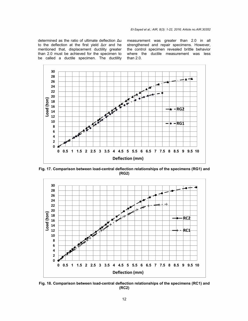
determined as the ratio of ultimate deflection Δu to the deflection at the first yield Δcr and he mentioned that, displacement ductility greater than 2.0 must be achieved for the specimen to be called a ductile specimen. The ductility
measurement was greater than 2.0 in all strengthened and repair specimens. However, the control specimen revealed brittle behavior where the ductile measurement was less than 2.0.
Fig. 17. Comparison between load-central deflection relationships of the specimens (RG1) and (RG2)
Fig. 18. Comparison between load-central deflection relationships of the specimens (RC1) and (RC2)
0
2
4
6
8
10
12
14
16
18
20
22
24
26
28
30
0 0.5 1 1.5 2 2.5 3 3.5 4 4.5 5 5.5 6 6.5 7 7.5 8 8.5 9 9.5 10
RG2
RG1
Load
(to
n)
Deflection (mm)
0
2
4
6
8
10
12
14
16
18
20
22
24
26
28
30
0 0.5 1 1.5 2 2.5 3 3.5 4 4.5 5 5.5 6 6.5 7 7.5 8 8.5 9 9.5 10
RC2
RC1Load
(to
n)
Deflection (mm)

El-Sayed et al.; AIR, 8(3): 1-22, 2016; Article no.AIR.30352
13
Fig. 19. Comparison between load-central deflection relationships of the specimens (RS1) and (RS2)
Fig. 20. Effect of the number of strengthening rows on the ultimate punching shear resistance
Fig. 21. Effect of the number of repair rows on the ultimate punching shear resistance
02
4
6
8
10
12
14
16
18
20
22
24
26
28
30
0 0.5 1 1.5 2 2.5 3 3.5 4 4.5 5 5.5 6 6.5 7 7.5 8 8.5 9 9.5 10
RS2
RS1
Load
(to
n)
Deflection (mm)

El-Sayed et al.; AIR, 8(3): 1-22, 2016; Article no.AIR.30352
14
Table 4. Main results of the tested specimens
Specimen code 1st crack Ultimate Ultimate load (specimen) ـــــــــــــــــــUltimate load (control)
Ductility Ki=Vcr/Δcr (Vul-Vcr)
Ku= ــــــــــــــ
(Δul-Δcr)
Stiffness degradation
Load (ton)
Δ cr
deflection (mm)
Load (ton)
Δ ul
deflection (mm)
Δ ul
ـــــــــ
Δ cr
(t/mm) (t/mm) (Ki-Ku)*100
ــــــــــــــــــــــــــ
Ki
C 8.00 3.25 16.50 6.29 1.00 1.94 2.46 2.80 13.59
RG1 9.50 2.85 21.45 7.49 1.30 2.63 3.33 2.58 22.74
RC1 9.50 2.40 22.89 7.79 1.39 3.25 3.96 2.42 38.83
RS1 10.00 2.75 22.17 7.89 1.34 2.87 3.64 2.37 34.89
RG2 11.00 2.95 27.15 9.63 1.65 3.26 3.73 2.42 35.16
RC2 11.20 2.65 29.31 9.93 1.78 3.75 4.23 2.49 41.14
RS2 10.50 2.65 28.79 9.85 1.74 3.72 3.96 2.54 35.89
SG1 8.70 2.70 20.31 7.02 1.23 2.60 3.22 2.69 16.59
SC1 9.00 2.60 21.93 6.94 1.33 2.67 3.46 2.98 13.93
SS1 9.80 2.95 20.98 7.21 1.27 2.44 3.32 2.62 21.00
SG2 11.00 3.30 26.96 9.34 1.63 2.83 3.33 2.64 20.73
SC2 11.00 3.00 28.75 9.65 1.74 3.22 3.67 2.67 27.20
SS2 10.50 3.15 28.16 9.73 1.71 3.09 3.33 2.68 19.48

5.4 Stiffness The un-cracked stiffness Ki and the ultimate stiffness Ku were obtained from the loaddeflection values of the tested specimens, as presented in Table. 4. It shows that the uncracked stiffness (Ki) is increased significantly when punching shear strengthening or repair systems were used. Using steel links, GFRP stirrups, and CFRP stirrups led to increase Ki by 31% to 49% for strengthened specimens and by 35% to 61% for repaired specimens. It's observed that strengthening and repair systems increase the first cracking load which causecracks appearance at a higher loading level which reduces the slope of the load deflection relationship after cracking load, this led to decrease the ultimate stiffness (Kustrengthened or repaired specimens except specimen SC1. Therefore, as stiffness (Ku) decreased, a considerable increase in the stiffness degradation was observed for all strengthened and repaired specimens.
Fig. 22. Cracking pattern of specimen (C)
Fig. 23.
El-Sayed et al.; AIR, 8(3): 1-22, 2016; Article no.AIR.30352
15
and the ultimate stiffness Ku were obtained from the load-deflection values of the tested specimens, as presented in Table. 4. It shows that the un-cracked stiffness (Ki) is increased significantly when punching shear strengthening or repair
used. Using steel links, GFRP stirrups, and CFRP stirrups led to increase Ki by 31% to 49% for strengthened specimens and by 35% to 61% for repaired specimens. It's observed that strengthening and repair systems increase the first cracking load which causes cracks appearance at a higher loading level which reduces the slope of the load deflection relationship after cracking load, this led to
crease the ultimate stiffness (Ku) for all strengthened or repaired specimens except
the ultimate ) decreased, a considerable
increase in the stiffness degradation was observed for all strengthened and repaired
5.5 Cracking Behavior and Failure
All the tested specimens were loaded until failed due to punching shear. For all specimens, the first crack was recorded, cracks propagation were monitored, and the mode of failure was determined. Table 4 shows the load value corresponding to cracking initiation (Vcr). Strengthening and repairsystems led to an increase of the first crackload. Cracks began firstly at the slab compression side near to the column edges. As the applied load increases the number and width of the cracks increase and new crand began to propagate in radial directions towards the slab edges. Also, fine cracks were observed running from column edges at tension side towards the slab edges in the three directions. For all the tested specimens, itwas observed that the column penetrated the slab at failure and the upper perimeter crack had a semi - rectangular shape at the slab tension face.
Fig. 22. Cracking pattern of specimen (C)
Cracking pattern of specimen (SG1)
; Article no.AIR.30352
and Mode of
All the tested specimens were loaded until iled due to punching shear. For all
specimens, the first crack was recorded, cracks propagation were monitored, and the mode of failure was determined. Table 4 shows the load value corresponding to cracking
n (Vcr). Strengthening and repair systems led to an increase of the first crack load. Cracks began firstly at the slab compression side near to the column edges. As the applied load increases the number and width of the cracks increase and new cracks develop and began to propagate in radial directions towards the slab edges. Also, fine cracks were observed running from column edges at tension side towards the slab edges in the three directions. For all the tested specimens, it
observed that the column penetrated the slab at failure and the upper perimeter crack had
rectangular shape at the slab tension

El-Sayed et al.; AIR, 8(3): 1-22, 2016; Article no.AIR.30352
16
Fig. 24. Cracking pattern of specimen (SC1)
Fig. 25. Cracking pattern of specimen (SS1)
Fig. 26. Cracking pattern of specimen (SG2)
Fig. 27. Cracking pattern of specimen (SC2)

Fig. 28.
Fig. 29. Cracking pattern of specimen (RG1)
Fig. 30. Cracking pattern of specimen (RC1)
Fig. 31. Cracking pattern of specimen (RS1)
El-Sayed et al.; AIR, 8(3): 1-22, 2016; Article no.AIR.30352
17
Fig. 28. Cracking pattern of specimen (SS2)
Fig. 29. Cracking pattern of specimen (RG1)
Fig. 30. Cracking pattern of specimen (RC1)
Fig. 31. Cracking pattern of specimen (RS1)
; Article no.AIR.30352

El-Sayed et al.; AIR, 8(3): 1-22, 2016; Article no.AIR.30352
18
Fig. 32. Cracking pattern of specimen (RG2)
Fig. 33. Cracking pattern of specimen (RC2)
Fig. 34. Cracking pattern of specimen (RS2)
5.6 Punching Shear Failure Angle (α) For all the tested specimens similar shapes of punching failure surface were observed, where the failure surfaces ended approximately at the same section - at the loading line - from column face but started from different sections from the column face - at the outermost row of punching shear reinforcement strengthening or repair - producing
different angles with horizontal as presented in Table 5. The punching shear failure angle (α) increased for all strengthened or repaired specimens compared to the control specimen.
6. ANALYTICAL MODEL All the tested specimens failed as a result of concrete exhaustion under punching shear

El-Sayed et al.; AIR, 8(3): 1-22, 2016; Article no.AIR.30352
19
stress at the critical section located at a distance d/2 from the outermost row of punching shear reinforcement. For the prediction of the ultimate test load, based on ACI 440 procedures, the following equation can be used to calculate the values of concrete nominal punching shear strength (vc) [11];
Vc
')6
110.33(= Cf
(MPa) (1)
Where; : ratio of the critical section distance from the column face to the slab effective depth 4 1;
ƒc' : concrete cylinder compressive strength;
For the specimens reinforced, strengthened or repaired with steel links the nominal punching shear strength may be expressed as:
vn=(vc+vs ) (2)
Where; vc : shear resisted by the concrete; vs : shear resisted by steel links;
Vs=(Av.fyv.d)/s (3)
Where;
Av : area of the vertical legs forming the punching shear reinforcement strengthening or repair units in one row;
fyv : yield stress of the used steel for punching shear reinforcement strengthening or repair units;
S : spacing between rows;
The punching shear force resisted by concrete only at any critical section can be calculated from the following equation;
Vc=(vc.b.d) (4)
Where;
vc : given by equation (5.6);
b : perimeter of the critical section (at a distance d/2 from the outermost row of punching shear reinforcement strengthening or repair);
In specimens strengthened with FRP, the nominal punching shear strength may be expressed as:
vn=(vc+vf) ≤ Vmax. (5)
Vmax = 0.60 'fc where Vf is the shear resisted by glass or carbon fiber;
= 0.95 (completely wrapped elements), this definition agree with strengthening stirrups types A;
= 0.85 (3-sides “U-wraps”), this definition agree with strengthening stirrups types B; Where; Vf : is the shear resisted by fiber reinforcement; The shear strength provided by the fiber reinforcement (Vf) can be determined by calculating the force resulting from the effective tensile stress in the fiber (ffe) which depnds on its effective strain (Єfe).
vf =(Afv.ffe.df)/sf (6)
Afv =ns.nv.tf.wf (7)
ffe=Єfe.Ef (8)
Where; Єfe = 0.004 (for completely wrapping arround all 4 sides) [12];
sf : spacing between fiber rows; tf : fiber thickness; wf : width of the fiber strip; nv : number of side row links; ns : number of vertical legs in one side of
row; Afv : area of fiber in one row; df : depth of fiber stirrups;
The above equations were applied to predict the ultimate punching shear load of the tested specimens. Table 6 shows a comparison between the calculated values of the ultimate load (Vu, cal.) and the corresponding experimental values (Vu, exp.). The equations used to predict the ultimate loads are moderately conservative, where the experimental values are higher than the calculated ones.

El-Sayed et al.; AIR, 8(3): 1-22, 2016; Article no.AIR.30352
20
Table 5. Characteristics of the observed failure mode
Notation Punching propagation distance (cm)
L/d Punching failure angle α
D1 D2 C 15 75 2.73 23.5 RG1 25 75 2.73 27.5 RC1 31 75 2.73 30.5 RS1 37 75 2.73 34.5 RG2 33 75 2.73 31.5 RC2 39 75 2.73 36 RS2 43 75 2.73 39 SG1 33 75 2.73 31.5 SC1 35 75 2.73 28.5 SS1 37 75 2.73 34.5 SG2 31 75 2.73 30.5 SC2 41 75 2.73 37.5 SS2 43 75 2.73 39
Table 6. Comparison of experimental and
predicted results
Notation Vu, exp. Vu, cal. Vu, exp.
Vu, cal. C 16.5 11.47 1.44 RG1 21.45 15.35 1.40 RC1 22.89 15.35 1.49 RS1 22.17 15.35 1.44 RG2 27.15 17.62 1.54 RC2 29.31 17.62 1.66 RS2 28.79 17.62 1.63 SG1 20.31 15.35 1.32 SC1 21.93 15.35 1.43 SS1 20.98 15.35 1.37 SG2 26.96 17.62 1.53 SC2 28.75 17.62 1.63 SS2 28.16 17.62 1.60
7. CONCLUSIONS For all the tested specimens, it was observed that the column penetrated the slab at failure and the upper perimeter crack had a semi - rectangular shape and observed at the slab tension face. Strengthening and repair systems were effective and improved significantly these connections punching shear behavior. All the used materials in this research for strengthening or repair led to increase the flexural rigidity which at the same loading level, lower deflection values were recorded for strengthened and repaired specimens, either
with steel links, GFRP or CFRP stirrups, in comparison with the control specimen. Strengthening and repair increased the initial cracking increased load by 9% to 38% for strengthened specimens and by 19% to 40% for repaired specimens and the ultimate punching shear capacity also increased by 23% to 74% for strengthened specimens and by 30% to 78% for repaired specimens. The CFRP intertwined stirrups was the best strengthening and repair material, which led to the highest improvement in the rigidity and the ultimate punching shear capacity. The strengthening and repair systems enhancement the ductility of these slabs by 26% to 66% for strengthened specimens and by 36% to 92% for repaired specimens. These systems led to increase the number of radial cracks, and, also, increased the distance between the punching shear surface and the column face.
The strengthening and repair systems enhancement the ductility of these slabs.
The prediction of ultimate shear strength based on ACI 440 gave underestimated strength for all the tested specimens, so, it is a conservative method, where the experimental values are higher than the calculated ones.
ACKNOWLEDGEMENTS
We would like to record our appreciation for the Faculty of Engineering in Benha, Benha

El-Sayed et al.; AIR, 8(3): 1-22, 2016; Article no.AIR.30352
21
University, for rendering the necessary support to carry out this research.
COMPETING INTERESTS Authors have declared that no competing interests exist. REFERENCES 1. Said AMT. Strengthening of R.c slab-
column connection to resist punching shear. ‖ Ph.D. thesis, Faculty of Engineering, Cairo University; 1998.
2. Gamal I. New punching shear Strengthening technique for concrete slab-column connections using FRP. Scientific Bulletin, El Mataria Faculty of Engineering Journal. 2004;93.
3. Omar El-Nawawy, Ayman Hussein Hosny, Eiad H. Zahran, Hamada Ali Hamada Mohamed. Improving punching shear behavior of flat RC Slabs. J Am Sci. 2015;11(7):122-129.
(ISSN: 1545-1003)
Available:http://www.jofamericanscience.org
4. Bompa DV, Muttoni A. Failure analysis of edge flat-slab column connections with shear reinforcement, fib Symposium Tel-Aviv 2013, Tel-Aviv, Israel. 2013;4.
5. Moussa A. Some additional arrangements to increase the punching shear capacity of reinforced concrete slab-column connections. ‖ 2nd Intr. Specialty conference on the conceptual approach to structural design, Milan, Italy. 2003;2.
6. Hasan Meisami M, Mostofinejad D, Nakamura H. Strengthening of flat slabs
with FRP fan for punching shear. Composite Structures; 2014. Available:http://dx.doi.org/10.1016/j.compstruct.2014.08.041
7. Ismail G, Abdel-Karem A, Debeiky A, Makhlouf M. Strenghtening and repair of reinforcement concrete slab-column connection subjected to punching shear using (CFRP - GFRP - Steel) Stirrups,‖ ICSSD 2012, Fourth International Conference on Structural Stability and Dynamics, India; 2012.
8. Khaleel GI, Shaaban IG, Elsayed KM, Makhlouf MH. Strengthening of reinforced concrete slab-column connection subjected to punching shear with frp systems. International Conference on Civil Engineering and Architecture, Barcelona-Span, August, 2013 and International Journal of Engineering and Technology (IJET); 2013.
9. Ramadan AMM. Repair and strengthening of slab-column connections with openings. ‖ Ph.D. thesis, Faculty of Engineering, Minoufiya University; 2007.
10. Hawkins NM, Bao A, Yamazaki J. Moment transfer from concrete slabs and edge column. ACI Journal. 1989;86(6):705-716.
11. Authorization No. 2-4.6-70: ―stud rails as shear reinforcement in the support zones of slabs point supports (zulassungsbescheid Nr. 2-4.6-70, kopfbolzen-dubelleisten als schubbewehrung im stuzenbereich punktforming gestutzter platten), ‖ Institute fur Baulechnik, Berlin; 1980.
12. ACI Committee 440: ―Guide for the design and construction of externally bonded FRP systems for strengthening concrete structures. ‖; 2000.

El-Sayed et al.; AIR, 8(3): 1-22, 2016; Article no.AIR.30352
22
APPENDIX
Properties of Steel Reinforcement
Nominal diameter mm
Grade Actual area cm2
Unit weight Kg/m
Yield strength Kg/cm2
Ultimate strength Kg/cm2
Elongation %
Ф8 24/35 0.470 0.372 3100 4800 26
Mechanical properties of Sikadur-330, given by the manufacturer
Property Value Tensile Strength 300 kg/cm2 (7 days at +23°C) Bond Strength Concrete fracture (> 4 N/mm2) Elongation at Break 0.9% (7 days at +23°C) E-Modulus Flexural:
38000 kg/cm2 (7 days at +23°C)
Tensile: 45000 kg/cm
2 (7 days at +23°C)
Mechanical properties of polyester material, according to the manufacturer
Property Value Tensile strength 110 kg/cm2 Elongation at break 9% Application temperature 15-30°C
_________________________________________________________________________________ © 2016 El-Sayed et al.; This is an Open Access article distributed under the terms of the Creative Commons Attribution License (http://creativecommons.org/licenses/by/4.0), which permits unrestricted use, distribution, and reproduction in any medium, provided the original work is properly cited.
Peer-review history: The peer review history for this paper can be accessed here:
http://sciencedomain.org/review-history/17229