replacement of 600-ampere bushing and 200-ampere …...this instruction sheet covers the of...
TRANSCRIPT
March 18, 2019
© S&C Electric Company 2014-2019, all rights reserved Instruction Sheet 695-530
S&C Vista® SD Underground Distribution SwitchgearPad-Mounted and Vault-Mounted StyleOutdoor Distribution (17.5 kV and 29 kV)
With Visi-Gap® Load Interrupter Switches and Visi-Gap® Fault Interrupters
Replacement of 600-Ampere Bushing and 200-Ampere Bushing-Well Adapters
Table of Contents
Section Page Section Page
IntroductionQualified Persons . . . . . . . . . . . . . . . . . . . . . . . . . . . 2Read this Instruction Sheet . . . . . . . . . . . . . . . . . . . 2Retain this Instruction Sheet . . . . . . . . . . . . . . . . . . . 2Proper Application . . . . . . . . . . . . . . . . . . . . . . . . . . 2Warranty . . . . . . . . . . . . . . . . . . . . . . . . . . . . . . . . . . 3Warranty Qualifications . . . . . . . . . . . . . . . . . . . . . . 3
Safety InformationUnderstanding Safety-Alert Messages . . . . . . . . . . . 4Following Safety Instructions . . . . . . . . . . . . . . . . . . 4Replacement Instructions and Labels . . . . . . . . . . . 4
Safety Precautions . . . . . . . . . . . . . . . . . . . . . . . . . . . . 5
Tools Needed . . . . . . . . . . . . . . . . . . . . . . . . . . . . . . . . . 6
200-Ampere Bushing-Well AdaptersRemoval . . . . . . . . . . . . . . . . . . . . . . . . . . . . . . . . . . .7Installation . . . . . . . . . . . . . . . . . . . . . . . . . . . . . . . . . .8
600-Ampere Bushing-AdaptersRemoval . . . . . . . . . . . . . . . . . . . . . . . . . . . . . . . . . . .9 Installation . . . . . . . . . . . . . . . . . . . . . . . . . . . . . . . . . 10
2 S&C Instruction Sheet 695-530
Qualified Persons WARNINGOnly Qualified Persons who are knowledgeable in the installation, operation, and maintenance of overhead and underground electric distribution equipment, along with all associated hazards, may install, operate, and maintain the equipment covered by this publication . A Qualified Person is someone who is trained and competent in:
• The skills and techniques necessary to distinguish exposed live parts from nonlive parts of electrical equipment
• The skills and techniques necessary to determine the proper approach distances corresponding to the voltages to which the Qualified Person will be exposed
• The proper use of special precautionary techniques, personal protective equipment, insulated and shielding materials, and insulated tools for working on or near exposed energized parts of electrical equipment
These instructions are intended ONLY for such Qualified Persons . They are not intended to be a substitute for adequate training and experience in safety procedures for this type of equipment .
Read this Instruction Sheet
NOTICERead this instruction sheet thoroughly and carefully before replacing 600-ampere bushing adapters or 200-ampere bushing-well adapters . Familiarize yourself with the Safety Information and Safety Precautions on pages 4 and 5 . The latest version of this publication is available online in PDF format at sandc.com/en/support/product-literature/ .
This instruction sheet covers the replacement of 600-ampere bushing adapters or 200-ampere bushing-well adapters used in S&C Vista SD Underground Switchgear.
Retain this Instruction Sheet
This instruction sheet is a permanent part of your SS&C Vista SD Underground Distribution Switchgear. Designate a location where you can easily retrieve and refer to this publication.
Proper Application WARNINGThe equipment in this publication must be selected for a specific application . The application must be within the ratings furnished for the equipment .
Introduction

S&C Instruction Sheet 695-530 3
Warranty The warranty and/or obligations described in S&C’s Price Sheet 150, “Standard Conditions of Sale – Immediate Purchasers in the United States” (or Price Sheet 153, “Standard Conditions of Sale – Immediate Purchasers Outside the United States)” plus any special warranty provisions, as set forth in the applicable product-line specification bulletin, are exclusive. The remedies provided in the former for breach of these warranties shall constitute the immediate purchaser’s or end user’s exclusive remedy and a fulfillment of the seller’s entire liability. In no event shall the seller’s liability to the immediate purchaser or end user exceed the price of the specific product that gives rise to the immediate purchaser’s or end user’s claim. All other warranties, whether express or implied or arising by operation of law, course of dealing, usage of trade or otherwise, are excluded. The only warranties are those stated in Price Sheet 150 (or Price Sheet 153), and THERE ARE NO EXPRESS OR IMPLIED WARRANTIES OF MERCHANTABILITY OR FITNESS FOR A PARTICULAR PURPOSE. ANY EXPRESS WARRANTY OR OTHER OBLIGATION PROVIDED IN PRICE SHEET 150 (OR PRICE SHEET 153) IS GRANTED ONLY TO THE IMMEDIATE PURCHASER AND END USER, AS DEFINED THEREIN. OTHER THAN AN END USER, NO REMOTE PURCHASER MAY RELY ON ANY AFFIRMATION OF FACT OR PROMISE THAT RELATES TO THE GOODS DESCRIBED HEREIN, ANY DESCRIPTION THAT RELATES TO THE GOODS, OR ANY REMEDIAL PROMISE INCLUDED IN PRICE SHEET 150 (or PRICE SHEET 153.)
Warranty Qualifications
The seller’s standard warranty does not apply to components not of S&C manufacture that are supplied and installed by the purchaser, or to the ability of seller’s equipment to work with such components.
Introduction

4 S&C Instruction Sheet 695-530
Safety Information
Understanding Safety-Alert Messages
Several types of safety-alert messages may appear throughout this instruction sheet and on labels and tags attached to your S&C Vista SD Underground Distribution Switchgear. Familiarize yourself with these types of messages and the importance of these various signal words:
DANGER“DANGER” identifies the most serious and immediate hazards that will likely result in serious personal injury or death if instructions, including recommended precautions, are not followed .
WARNING
“WARNING” identifies hazards or unsafe practices that can result in serious personal injury or death if instructions, including recommended precautions, are not followed .
CAUTION“CAUTION” identifies hazards or unsafe practices that can result in minor personal injury if instructions, including recommended precautions, are not followed .
NOTICE“NOTICE” identifies important procedures or requirements that can result in product or property damage if instructions are not followed .”
Following Safety Instructions
If you do not understand any portion of this instruction sheet and need assistance, contact your nearest S&C Sales Office or S&C Authorized Distributor. Their telephone numbers are listed on S&C’s website sandc.com, or call the S&C Global Monitoring and Support Center at 1-888-762-1100.
NOTICE
Read this instruction sheet thoroughly and carefully before replacing 600-ampere bushing adapters or 200-ampere bushing-well adapters .
Replacement Instructions and Labels
If requiring additional copies of this instruction sheet, contact your nearest S&C Sales Office, S&C Authorized Distributor, S&C Headquarters, or S&C Electric Canada Ltd.
It is important that any missing, damaged, or faded labels on the equipment be replaced immediately. Replacement labels are available by contacting your nearest S&C Sales Office, S&C Authorized Distributor, S&C Headquarters, or S&C Electric Canada Ltd.

S&C Instruction Sheet 695-530 5
Safety Precautions
DANGER
S&C Vista SD Underground Distribution Switchgear operates at high voltage . Failure to observe the precautions below will result in serious personal injury or death.
Some of these precautions may differ from your company’s operating procedures and rules . Where a discrepancy exists, follow your company’s operating procedures and rules .
1. Qualified Persons. Access to the Vista SD Underground Distribution Switchgear must be restricted only to qualified persons . See “Qualified Persons” on page 2 .
2. Safety Procedures. Always follow safe operating procedures and rules . Always maintain proper clearance from energized components .
3. Personal Protective Equipment. Always use suitable protective equipment, such as rubber gloves, rubber mats, hard hats, safety glasses, and arc-flash clothing in accordance with safe operating procedures and rules .
4. Doors. High-voltage compartment doors must be securely closed and latched, with padlocks in place at all times unless work is being performed inside the enclosure .
5. Key Interlocks. Optional key interlocks, if furnished, must be in place . Check the operating sequence of key interlocks to verify proper sequencing . After the switchgear is installed, destroy all duplicate keys or make them accessible only to authorized persons so the key-interlock scheme will not be compromised .
6. Opening Doors. Do not apply any undue force when attempting to open a door . The use of undue force may damage the door-latching mechanism .
7. Safety Labels. Do not remove or obscure any of the “DANGER,” “WARNING,” “CAUTION,” or “NOTICE” labels .
8. Energized Bushings. Always assume the bushings are energized unless proven otherwise by test, by visual evidence of an Open-Circuit condition at the load-interrupter switch or fault interrupter, or by observing the load-interrupter switch or fault interrupter is grounded .
9. Backfeed. Bushings, cables, load-interrupter switches, and fault interrupters may be energized by backfeed .
10. Grounding.
• Vista SD Switchgear must be connected to a suitable earth ground before energizing, and at all times when energized .
• The ground wire(s) must be bonded to the system neutral, if present . If the system neutral is not present, proper precautions must be taken to ensure that the local earth ground cannot be severed or removed .
• After the switchgear has been completely disconnected from all sources of power and tested for voltage, properly ground the load-interrupter switches and fault interrupters before touching any bushings or components that are to be inspected, replaced, serviced, or repaired .
11. Load-Interrupter Switch or Fault Interrupter Position.
• Always confirm the Open/Closed position of the load-interrupter switch or fault interrupter by visually observing the position of the isolating disconnect .
• Load-interrupter switch or fault interrupter may be energized by backfeed .
• Load-interrupter switch or fault interrupter may be energized in any position .
12. Maintaining Proper Clearance. Always maintain proper clearance from energized components .
6 S&C Instruction Sheet 695-530
Tools Needed
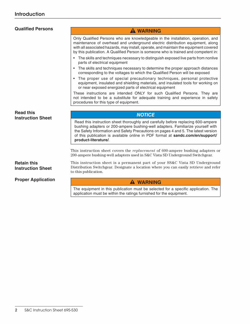
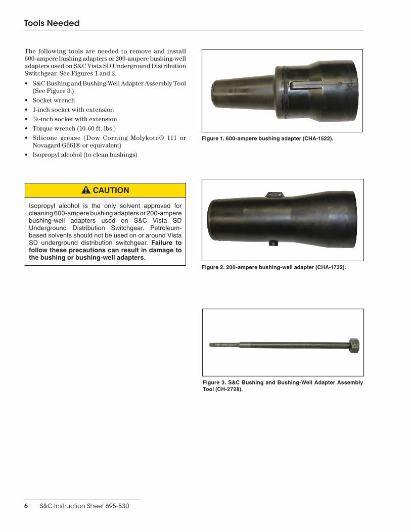
The following tools are needed to remove and install 600-ampere bushing adapters or 200-ampere bushing-well adapters used on S&C Vista SD Underground Distribution Switchgear. See Figures 1 and 2.
• S&C Bushing and Bushing-Well Adapter Assembly Tool (See Figure 3.)
• Socket wrench
• 1-inch socket with extension
• ⅞-inch socket with extension
• Torque wrench (10-60 ft.-lbs.)
• Silicone grease (Dow Corning Molykote® 111 or Novagard G661® or equivalent)
• Isopropyl alcohol (to clean bushings)
Figure 1. 600-ampere bushing adapter (CHA-1522).
Figure 2. 200-ampere bushing-well adapter (CHA-1732).
Figure 3. S&C Bushing and Bushing-Well Adapter Assembly Tool (CH-2728).
CAUTION
Isopropyl alcohol is the only solvent approved for cleaning 600-ampere bushing adapters or 200-ampere bushing-well adapters used on S&C Vista SD Underground Distribution Switchgear . Petroleum-based solvents should not be used on or around Vista SD underground distribution switchgear . Failure to follow these precautions can result in damage to the bushing or bushing-well adapters.

S&C Instruction Sheet 695-530 7
200-Ampere Bushing-Well Adapters
RemovalFollow these steps to remove 200-ampere bushing-well adapters:
STEP 1. De-energize and ground the cables following user’s operating procedures and rules. Then, remove the cables from the switchgear assembly.
DANGERBefore touching the bushing to be replaced, always disconnect load-interrupter switches and fault interrupters from all power sources (including backfeed), test for voltage, and properly ground them . Failure to observe these precautions will result in serious personal injury or death.
STEP 2. Using a socket wrench with a ⅞-inch socket and socket extension, remove the threaded stud at the center of the bushing-well adapter. Rotate the stud counterclockwise. See Figure 4.
STEP 3. Fully insert the S&C Bushing and Bushing-Well Adapter Assembly Tool (CH-2728) into the bushing-well adapter. By hand, rotate the tool a few degrees in either direction to engage the hex feature of the tool with the bushing-well adapter attachment bolt.
STEP 4. Using a socket wrench with a 1-inch socket and socket extension, rotate the S&C Bushing and Bushing-Well Adapter Assembly Tool counterclockwise to loosen the bushing-well adapter. See Figure 5.
STEP 5. Grasp the bushing-well adapter, and continue rotating the S&C Bushing and Bushing-Well Adapter Assembly Tool counterclockwise until the bushing-well adapter can be pulled off of the bushing interface. See Figure 6.
Figure 4. 200-Ampere bushing-well adapter with threaded stud installed.
Figure 5. Loosening the bushing-well adapter.
Figure 6. Removing the bushing-well adapter.
Threaded stud

8 S&C Instruction Sheet 695-530
200-Ampere Bushing-Well Adapters
Installation
Follow these steps to install 200-ampere bushing-well adapters:
STEP 1. Thoroughly clean the light-gray conical bushing interface on the switchgear assembly using a clean lint-free cloth dipped in isopropyl alcohol. Allow alcohol to thoroughly evaporate. Then, apply a smooth, even coating of silicone grease.
STEP 2. Clean the inside of the larger diameter end of the replacement bushing-well adapter with a clean lint-free cloth dipped in isopropyl alcohol. Allow alcohol to thoroughly evaporate. Then, apply a smooth, even coating of silicone grease.
STEP 3. To attach the bushing-well adapter to the bushing interface on the switchgear assembly, insert the S&C Bushing and Bushing-Well Adapter Assembly Tool into the bushing-well adapter. By hand, rotate the tool a few degrees in either direction to engage the hex feature of the tool with the bushing-well adapter attachment bolt. Holding the tool and the bushing-well adapter as an assembly, position the bushing-well adapter on the bushing interface while aligning the orientation features. See Figures 7 and 8.
STEP 4. While pushing on the bushing-well adapter, by hand, rotate the S&C Bushing and Bushing-Well Adapter Assembly Tool clockwise to engage the bolt in the bushing-well adapter with the bushing interface on the switchgear assembly. See Figure 9. Continue rotating the wrench clockwise until the bushing-well adapter is fully attached to the bushing interface of the switchgear assembly; tighten and torque to a value of 50-60 ft.-lbs.
Check that the bushing-well adapter is posi-tioned under the ground clip. See Figure 16 on page 10.
STEP 5. Insert the threaded stud into the bushing-well adapter, with the larger diameter end facing inwards. Using a socket wrench with a socket extension and a ⅞-inch socket rotate the stud clockwise; tighten the stud to a value of 12 ft.-lbs. of torque. See Figure 10.
STEP 6. Clean the bushing-well adapter interface using a soft lint-free cloth dipped in isopropyl alcohol. Allow the alcohol to thoroughly evaporate. Apply a smooth, even coating of silicone grease before attaching the cables to the switchgear assembly.
Figure 9. Tightening the bushing-well adapter.
Figure 7. Orientation features aligned.
Figure 8. Orientation features misaligned.
Larger diameter Smaller diameter
Figure 10. Larger diameter of threaded stud faces into bushing-well adapter.

S&C Instruction Sheet 695-530 9
600-Ampere Bushing Adapters
Removal
Follow these steps to remove 600-ampere bushing adapters:
STEP 1. De-energize and ground the cables following user’s operating procedures and rules. Then remove the cables from the switchgear assembly.
DANGERBefore touching the bushing to be replaced, always disconnect load-interrupter switches and fault interrupters from all power sources (including backfeed), test for voltage, and properly ground them . Failure to observe these precautions will result in serious personal injury or death.
STEP 2. Fully insert the S&C Bushing and Bushing-Well Adapter Assembly Tool (CH-2728) into the bushing adapter. By hand, rotate the tool a few degrees in either direction to engage the hex feature of the tool with the bushing adapter attachment bolt.
STEP 3. Using a socket wrench with a 1-inch socket and socket extension, rotate the S&C Bushing and Bushing-Well Adapter Assembly Tool counterclockwise to loosen the bushing adapter. See Figure 11.
STEP 4. Grasp the black portion of the bushing adapter, NOT the dark gray portion (see Figure 12), and continue rotating the S&C Bushing and Bushing-Well Adapter Assembly Tool counterclockwise until the bushing adapter can be pulled off the bushing interface.
Do NOT grasp the gray tapered portion of the bushing adapter, as it is covered with silicone grease. See Figure 13.
Figure 11. Loosening the bushing adapter.
Figure 12. Correct method for removal of the bushing adapter.
Figure 13. Incorrect method for removal of the bushing adapter.
10 S&C Instruction Sheet 695-530
600-Ampere Bushing Adapters
InstallationFollow these steps to install 600-ampere bushing adapters:
STEP 1. Thoroughly clean the light-gray conical bushing interface on the switchgear assembly using a clean lint-free cloth dipped in isopropyl alcohol. Allow alcohol to thoroughly evaporate. Then, apply a smooth, even coating of silicone grease.
STEP 2. Clean the dark-gray recessed cone on the inside of the bushing adapter with a clean lint-free cloth dipped in isopropyl alcohol. Allow alcohol to thoroughly evaporate. Then, apply a smooth, even coating of silicone grease.
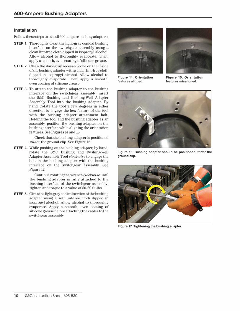
STEP 3. To attach the bushing adapter to the bushing interface on the switchgear assembly, insert the S&C Bushing and Bushing-Well Adapter Assembly Tool into the bushing adapter. By hand, rotate the tool a few degrees in either direction to engage the hex feature of the tool with the bushing adapter attachment bolt. Holding the tool and the bushing adapter as an assembly, position the bushing adapter on the bushing interface while aligning the orientation features. See Figures 14 and 15.
Check that the bushing adapter is positioned under the ground clip. See Figure 16.
STEP 4. While pushing on the bushing adapter, by hand, rotate the S&C Bushing and Bushing-Well Adapter Assembly Tool clockwise to engage the bolt in the bushing adapter with the bushing interface on the switchgear assembly. SeeFigure 17.
Continue rotating the wrench clockwise untilthe bushing adapter is fully attached to thebushing interface of the switchgear assembly; tighten and torque to a value of 50-60 ft.-lbs.
STEP 5. Clean the light gray conical section of the bushing adapter using a soft lint-free cloth dipped in isopropyl alcohol. Allow alcohol to thoroughly evaporate. Apply a smooth, even coating of silicone grease before attaching the cables to the switchgear assembly.
Figure 17. Tightening the bushing adapter.
Figure 14. Orientation features aligned.
Figure 15. Orientation features misaligned.
Figure 16. Bushing adapter should be positioned under the ground clip.