report 1131 - unt digital library
TRANSCRIPT

,’ /,”
,; .’
- ;‘ .’
.’
,, -_ ;- ” - / \ ,\,
.,, .:

REPORT 1131
DEFLECTION AND STRESS ANALYSIS OF THIN SOLID WINGS OF ARBITRARY PLAN FORM
WITH PARTICULAR REFERENCE TO DELTA WINGS
By MANUEL STEIN, J. EDWARD ANDERSON, and JOHN M. HEDGEPETH
Langley Aeronautical Laboratory, Langley Field, Vs.

National Advisory Committee for Aeronautics Headquarters, 17’24 F Street NW., Washington 26, D. C.
Created by act of Congress approved March 3, 1915, for the supervision and direction of the scientific study of the problems of flight (U. S. Code, title 50, sec. 151). Its membership was increased from 12 to 15 by act approved March 2,1929, and to 17 by act approved May 25,1948. The members are appointed by the President, and serve as such without compensation.
JEROME C. HIJNSAKER, SC. D., Massachusetts Institute of Technology, Chairman
DETLEV W. BRONK, PH. D., President, Rockefeller Institute for Medical Research, Vice Chairman
HON. JOSEPH P. ADAMS, member, Civil Aeronautics Board. ALLEN V. ASTIN, PH. D., Director, National Bureau of Standards. LEONARD CARMICHAEL, PH. D., Secretary, Smithsonian Institu-
tion. LAURENCE C. CRAKUE, Lieutenant General, United States Air
Force, Deputy Chief of Staff (Development). JAMES H. DOOLITTLE, SC. D., Vice President, Shell Oil Co. LLOYD HARRISON, Rear Admiral, United States Navy, Deputy
and Assistant Chief of the Bureau of Aeronautics. R. M. HAZEN, B. S.; Director of Engineering, Allison Division,
General Motors Corp. WILLIAM LITTLEWOOD, M. E., Vice President-Engineering,
American Airlines, Inc.
HON. ROBERT B. MURRAY, JR., Under Secretary of Commerce for Transportation.
RALPH A. OFSTIR, Vice Admiral, United States Navy, Deputy Chief of Naval Operations (Air).
DONALD L. PUTT, Lieutenant General, United States Air Force, Commander, Air Research and Development Command.
ARTHUR E. RAYMOND, SC. D., Vice President-Engineering, Douglas Aircraft Co., Inc.
FRANCIS W. REICHELDERFER, SC. D., Chief, United States Weather Bureau.
THEODORE P. WRIQHT, SC. D., Vice President for Research, Cornell University.
Ho-on L. DRYDEN, PH. D., Director JOHN F. VICTORY, LL. D., &ccutivc Secretary
JOEN W. CROWLEY, JR., B. S., Associate Director for Research E. H. CHAMBERLIN, Executive Ofleer
HENRY J. E. REID, D. Eng., Director, Langley Aeronautical Laboratory, Langley Field, Vs.
SMITH J. DEFRANCE, D. Eng., Director, Ames Aeronautical Laboratory, Moffett Field, Calif.
EDWARD R. SHARP, SC. D., Director, Lewis Flight Propulsion Laboratory, Cleveland Airport, Cleveland, Ohio
LANGLEY AERONAUTICAL LABORATORY, AMES AERONAUTICAL LABORATORY, LEWIS FLIGHT PROPULSION LABORATORY, Langley Field, Va. Moffett Field, Calif. Cleveland Airport, Cleveland, Ohio
Conduct, under un@ed control, for all agencies, of scientific research on the fundamental problems of flight
1111 I I II

REPORT 1131
DEFLKTION AND STRES? ANALYSIS OF THIN SOLID WINGS OF ARBITRARY PLAN FORM WITH PARTICULAR REFERENCE TO DELTA WINGS et
By MANUEL STEIN, J. EDWARD ANDERSON, and JOHN M. HEDCEPETH
SUMMARY
The structural analysis of arbitrary solid cantilever wings by small-dejection thin-plate theory is reduced to the solution of linear ordinary differential equations by the assumption that the chordwise desections at any spanwise station may be ex- pressed in the form of a power series in which the coeficients are junctions of the spanwise coordinate. If the series is limited to the jirst two and three terms (that is, $j linear and parabolic chordwise deflections, respectively, are assumed), the dijerential equations for the coeficients are solved exactly for unijormly loaded solid delta wings of constant thickness and of symmetrical double-wedge airfoil section with constant thickness ratio. For cases for which exact solutions to the digerential equations cannot be obiained, a numerical procedure is derived. Experi- mental deflection and stress data for constant-thickness delta- plate specimens of 45” and BOO sweep are presented and are -found to compare favorably with the present theory.
INTRODUCTION
One of the present trends in the development of high-speed airplanes and missiles is toward the use of thin low-aspect- ratio wings. The structural analysis of these wings often cannot be based on beam theory since the structural defor- mations may vary considerably from those of a beam and, indeed, may more closely approach those of a plate. In cases where the wing construction is solid or nearly solid the use of plate theory in the analysis is particularly valid, and it is this type of wing which is considered in the present report.
Exact solutions to the partial-differential equation of plate theory are not readily obtained, especially for plates of arbitrary shape and loading; however, a number of approxi- mate solutions to specific problems on cantilever plates have appeared in the literature (see, for example, refs. 1 to 7). Of the approaches used in these references, only the one in references 6 and 7 is readily applicable to plates of arbitrary plan form, thickness distribution, and load distribution; thus it is the most useful one for the analysis of actual wings.
In reference 6 the cantilever-plate problem is simplified by the assumption that the deformations of the plate in the chordwise direction (parallel to the root) are linear. By minimizing the potential energy of the plate, the partial- differential equation of plate theory is replaced by two
simultaneous ordinary differential equations for the spanwise variations of the bending deflection and twist. In reference 7 the same ordinary differential equations are obtained in a different manner. Refinement of the analysis by inclusion of the effect of parabolic, cubic, or higher-order chordwise camber terms is indicated in reference 6, and as the order of refinement is increased a corresponding increase in the num- ber of ordinary differential equations is obtained.
In the present report, which is an extension of reference 6, a general set of ordinary differential equations is presentecl which may be used to obtain any desired degree of approxi- mation to the deflection of the plate. These equations are solved exactly for several cases of delta plates under uniform load first by considering linear chordwise deformation only and second by including the effect of parabolic chordwise camber. Comparisons are drawn between the stresses and deflections computed from the equations of each approxi- mation and also with some experimental results.
The differential equations presented contain coefficients that depend on the plan form and stiffness distribution of the plate and on the loading. In this report, the plates con- siderecl in detail have coefficients such that the differential equations can be solved exactly; however, in cases for which exact solutions cannot be obtained a numerical procedure must be used. One such procedure is derived and its accuracy is demonstrated.
SYMBOLS
1 c P
t t ao
length of plate measured perpendicular to root root chord of plate lateral load per unit area, positive in z-
direction local thickness of plate average thickness of plate
n a
local flexural stiffness, Et3 12(1--Z)
flexural stiffness based on average thickness, Et,,
12(1-j?) E modulus of elasticity of material P Poisson’s ratio W deflection of plate, positive in z-direction x, y, 2 coordinates defined in figure 1
1 Supersedes NACA TN 2621, “Deflection and St.ress Analysis of Thin Solid Wings of Arbitrary Plan Form With Particular Reference to Delta Wings” by Manuel Stein, J. Edward hnderson, and John M. Hedgepeth, 1952.

L
REPORT 113 l-NATIONAL ADVISORY COMMITTEE FOR AERONAUTICS
ld FIGURE l.-Coordinate system used in the present analysis for a canti-
lever plate of arbitrary shape with arbitrary thickness variation.
function of 2, coefficient in power series for
deflection w=%$~ cpn(x)yn
functions defining plan form (see fig. 1)
variable obtained by transformation x1 = 1-z 1 normal stresses shear stress maximum principal stress
1 aspect-ratio parameter, ;
RESULTS
The derivation of the general set of ordinary differential equations is given in appendix A. The general procedure outlined in reference 6 is followed; that is, the deflection of the plate w is expandecl into a power series in y the chord- wise coordinate with coefficients which are functions of x the spanwise coordinate (see fig. 1)
w=cp~(x:)+cpl(x)Y+cp2(x)Y2+ . . . +(PN(x)YN (1)
Equation (1) is substituted into the expression for the po- tential energy of the plate-load combination which is in turn minimized by the calculus of variations with respect to each of the coefficients qn. The results of the variational procedure appear as N+l simultaneous difl’erentinl equa.- tions with the coefficients (Pi as unknowns.
By taking a sufficient number of terms in the expansion of w, the resulting differential equations can be usecl to ob- tain any desired degree of accuracy in the solution for the deflections of any given cantilever plate subjected to an arbitrary lateral load. Of most interest, perhaps, are the particular cases for N=l and N=2, which are obtained from the general set of equations and are simplified in appendix A. The case for N=l (also derived in refs. 6
and 7) includes linear chordwise deflections, and the case for N=2 takes into account parabolic chordwise curvature. Although for most practical problems the solution by the parabolic theory should be adequate, cases might exist in which cubic, quartic, or even higher-order chordwise terms should be included, depending on the convergence of the series for the configuration considered.
The particular equations for N= 1 and N=2 are used to determine the deflections and stresses of the following can- tilever plates subjected to uniform lateral load :
(1) A 45’ delta plate of uniform thickness (2) A 60’ delta plate of uniform thickness (3) A 45” delta plate of symmetrical double-wedge airfoil
section with constant thickness ratio Fortunately, for these configurations, the solution can be
carried out exactly by both the linear and parabolic theories, and the details of these exact solutions are included in appendix B. In general, however, exact solutions cannot be obtained and some numerical method must be used. One such method, based on replacing derivatives by their first-orcler-approximation difference forms, is derived in appendix C.
A summary of the results for the three particular problems is shown in figures 2 to 11. Deflections obtained by the
.02
1-
.4 \o
.Ol
.2 IF 0
I I
rc-i
r
Y _ ---
_- 1
m L
__ -_
0 Experiment O-- Linear p- Parabolic Theory
--- --o
. .4 .6 .8 3
FIGURE 2.-Deflections of a 45’ delta plate of uniform thickness uniform load.

linear theory and the parabolic theory for the three con- figurations are compared in figures 2, 3, and 4. Stresses obtained by the linear theory and the parabolic theory for the three configurations are compared in figures 5, 6, and 7. Where available, experimental deflections and stresses are also shown in these figures. The details of the procedure used to obtain the experimental deflections .of the 45’ and’:60 uniform-thickness plates and the experi- mental stresses in the 45O uniform-thickness plate are con- tained in appendix D ; whereas the experimental root stresses for the 60’ uniform-thickness plate were obtained from reference 8. Figures 8 to 11 present the comparison be- tween deflections and stresses computed from the exact solutions of the differential equations and those computed from the numerical solutions of the same equations.
DISCUSSION
The results shown in figures 2 and 3 indicate that, with regard to deflections, either the linear theory or the parabolic theory is adequate for the case of a constant-thickness delta plate subjected to a uniform load, the comparison being some- what better for the 60’ plate than for the 45’ plate. If accurate slopes in the chordwise direction (angle of attack)
.07 x/l I I 01.0
.06
Experiment 0- - Linear b- Parabolic
FIGURE 3.-Deflections of a GO0 delta plate of uniform thickness under uniform load.
are desired, however, the parabolic theory must be used because the error in the angle of attack as computed by the linear theory is as much as 30 percent (see figs. 2 and 3). The appreciable anticlastic curvature, evidenced by the experimental results of figures 2 and 3, may be important aerodynamically and is, of course, not taken into account by the linear theory.
The apparent convergence of the aforementioned series in the case of the double-wedge-section plate (see fig. 4) implies that the linear theory is adequate for this case. The lack of chordwise curvature in the result obtained by the parabolic theory is attributable to the fact that the natural tendency of the plate to have anticlastic curvature is canceled by the opposite tendency of the thin edges to bend down under the load. Unfortunately, no experimental results are available for this configuration.
In figure 4 the plate stiffness D in the nondimensional parameter wD/$ is the local value of D at a point where the thickness is equal to the average thickness of the plate as a whole. Thus the results of figure 4 are comparable with the- results of figure 2 on an equal-weight basis. It can be seen that the deflections of the double-wedge-section, constant-thickness-ratio plate are everywhere less than
.06
I I
0- - Linear b- Parabolic 1 Theory
.6 Y/C
.8 1.0
FIGURE 4.-Deflections of a 45’ delta plate of symmetrical double- wedge airfoil section and constant thickness ratio under uniform load. ij= Et,.3 -.
12(1-/q

REPORT 1131-NATIONAL ADVISORY COMMITTEE FOR AERONAUTICS
those of the uniform-thickness plate although they increase rapidly near the tip. This curling-up or singularity in slope at the tip is a result of using a smalldeflection theory and probably would not be so marked in an actual case.
The stress results for the 45’ and 60’ uniform-thickness delta plates indicate that both the linear and the parabolic theories are adequate and that the parabolic theory is better than the linear theory only near the root. It should be noted that, although the maximum principal stress over a large part of the 45’ plate is plotted in figure 5, only the stresses
normal to the root along the line ;=0.0087 of the 60° plate
are plotted in figure 6 since only these stresses are given in reference 8. (The maximum principal stress and the stress normal to the root are theoretically equal at the root since the root shear stress is zero.)
Experimental data are lacking for the double-wedge-section delta plate and, therefore, only theoretical stresses are shown in figure 7. As in the case of deflections, the results obtained from the linear theory and those obtained from the parabolic theory are almost coincident, the clifference being greatest near the root. Figure 7 has also been plotted so that the results are directly comparable with those for the 45’
+ 1 --. i : - I 4
\ / ~ Por \
.6 Y/C
FIGURE B.-Maximum principal stresses in a 45’ delta plate of uniform thickness under uniform load.
uniform-thickness plate in figure 5 on an equal-weight basis. As can be expected, the double-wedge-section, constant-thickness-ratio plate is a better design structurally; the stresses in the double-wedge-section plate are everywhere smaller and are almost constant in the spanwise direction.
The theoretical results in figures 2 to 7 have been obtained from exact solutions of the differential equations of the linear and parabolic theories. In order to test the reliability of the numerical method derived in appendix C, the differ- ential equations were also solved numerically. The results shown in figures 8 and 9 indicate that the agreement is good between the numerical solution in which five equal intervals u-em used and the exact solution of the differential equations for the case of the 45O uniform-thickness plate. The same good agreement can be expected in other cases where the thickness and load distributions are not too erratic and where the plate stiffness does not go to zero at the tip-that is, when no singularities appear at the tip.
2.4
I .6
.8
1 I
Experiment (ref. 8) _ -O- Linear
- Parabolic > Theory
.4 \
0
-.40 .2 .4 Y/C
.6 .8
FIGURE 6.--Normal-stress distribution near the root at F=O.OOSi >
of
a 60” delta plate of uniform thickness under uniform load.

_.._._.. . . --.-- .- .,,.., _..._-.-.- -~.
,;,,,- r. ‘. ‘“7,4l)mriy,i :. . fw.h c-. _. ; - :,: -. :: :: -! _. .._,i ,- , = ,_’ ..,., .- --&- ., _*&
r.@&.?< : :.: _,. i, , .-. .~ I -T--
DEFLECTION AND STRESS ANALYSIS OF THIN SOLID WINGS OF"ARRITRARY PLm FORM 5
Since the efficacy of the numerical method depends on how well parabolic arcs fit the various functions between stations, serious error can result from blind application. An example of the seriousness of these errors and of the manner in which they can be remedied is shown in figures i0 and 11. In these figures a comparison is made between exact and numerical results obtained on the 45’ double-wedge-section, constant-thickness-ratio plate. As can be expected, the five-station numerical solution fails to follow the exact solu- tion in the neighborhood of the singularity at the tip. Since the region of trouble is localized at the tip, a reasonable remedy would be to decrease the spacing of the station points near the tip. This decrease in spacing may be accomplished either by using a greater number of equally spaced stations or by using unequally spaced stations crowded near the tip. The increase in accuracy obtained by increasing the number of equally spaced station points to ten is shown in figures 10 and 11.
CONCLUDING REMARKS
The general method presented herein for finding deflec- tions and stresses of solid or nearly solid wings is, in principle,
2.0 I I
Y d=T+Ty
I .6
I----!+
7
II
FIGURE 7.-Maximum principal stress in a 45’ delta plate of symmet- rical double-wedge airfoil section and constant thickness ratio under uniform load.
capable of yielding arbitrarily accurate results for any con- figuration. It is seen that, for the examples considered, only the Crst two or three terms in the series expansion need be considered to obtain adequate accuracy. In addition, for most practical plate-like wings with clamped roots the first two or three terms will probably be adequate, although problems may exist wherein mom terms are needed.
The numerical procedure, derived for application in cases where exact solutions cannot be obtained, gives good agree- ment when compared with exact solutions if enough stations are taken along the span. ‘rhe necessary number of stations is dependent on the type of thickness and loading distribution considered, five equally spaced stations being enough for the uniform-thickness delta wing subjected to uniform loading and ten being necessary for the double-wedge-section, constant-thickness-ratio delta wing subjected to uniform loading.
LANGLEYAERONAUTICALLABORATORY, NATIONAL ADVISORY COMMITTEE FOR AERONAUTICS,
LANGLEY FIELD, VA., November SO, 1961.
.06-
0 -1 ~~$rica’} Linear
A Numerical Porobo,ic 7 Exact )
FIGURE S.-Numerical and exact solutions of the differential equations for the deflections of the free edges of a 45’ delta plate of uniform thickness under uniform load.

2.0
Cl
\ 1.6 \
\
- \
1.2 \
\ 2 cd _
2 \
Pl \
I3 ‘\y=o
\
/-L / \
.4 /
/y=CQ-f)
0 .2
REPORT 113 l-NATIONAL ADVISORY COMMITTEE FOR AERONAUTICS
L
I- c
1 0 -I-- f
FIGURE 9.-Numerical and exact solutions of the differential equations (obtained by assuming linear chordmise deflections) for the maximum principal stresses along the free edges of a 45’ delta plate of uniform thickness under uniform load.
.Oi
.ce
.0:
.oL
WD
p14
.O:!
.02
.Ol
0
701,
T t II L-
C
L b+- - l-1-4 ”
-I--
FIGURE lO.-Numerical and exact solutions of the differential equations (obtained by assuming linear chordmise deflections) for the deflec- tions along the free edges of a 45” delta plate of symmetrical doublc- wedge airfoil section and constant thickness ratio under uniforq load

I . DEFLECTION_AND S’I’RESS ANALYSIK OF THIN SOLID, WINGS -OF ARBITBaARY PLAN FORM 1 .,* .1 .7
I .6 -
1.2-
&- 2 0 5 stotion solution 0 IO- stotion solution
Numerico,
P12 -- Exact
.8
FIGURE Il.-Numerical and exact solutions of the differential equa- tions (obtained by assuming linear chordwise deflections) for the
masimum principal stress along the line g=f ( >
1-s 1 of a 45’ delta
plate of symmetrical double-wedge airfoil section and constant thickness ratio under uniform load.
APPENDIX A DERIVATION OF DIFFERENTIAL EQUATIONS
The structure considered herein is a thin, elastic, isotropic, cantilever plate of arbitrary plan form and slowly varying thickness subjected to distributed lateral load (see fig. 1). By assuming that the deflection of the plate can be repre- sented by a power series in the chordwise coordinat,e and by applying the minimum-potential-energy principle, a set of ordinary differential equations in the spanwise coordinate is obtained from which the coefficients of the power series may be determined. First the general set of equations is derived; then the particular equations for the cases of linear chordwise deflections and parabolic chordwise cleflections are deduced from the general set and simplified.
General equations,-The potential energy of the system under consideration is
in which
and p&y) is the distributed lateral load.

REPORT 113 l-NATIONAL ADVISORY COMMITTEE FOR AERONAUTICS
The assumption is made that the deflection w can be represented by the power series
Substitution of this expression for w into equation (Al) gives
Potential energy= I i
“dx $ go nl I~m+n+l~m”~n”Smn Cm- 1) (n-1) ~+~-~(~,cp,-t- 0
2j.m (n- 1)~ m+n-l(pm”~bn+2(1--)172nam+n-1~m’~nl 1-g *.+w.)
in which
ur= .I‘ c;; mx,Y)Y’-‘dY (r= 1,2, . . . 2N+l)
p,= s c;; pCw/W’dy (T= 1,2, . . . NSl)
W)
(A3)
(A4)
and the primes denote differentiation with respect to x. Minimization of the potential energy by means of the calculus of variations gives
G(Potentia1 energy)=0
= f m$o go [u,+,+l(cpm”d~,~“+(p,“6~,“)+mn(m- 1) b- l)um+n-3(~mG~a+‘PnG’Pm)f
Integrating by parts and collecting terms results in
S 2 O=
0 dx ne 6~ ime0 Nu,+,+,cpm”)“+~m Cm- 1) (um+n-l&“- 2 (l-4 m~(um+n-lcpm’)‘+w(~- 1) um+n-l(om”+
pm(m-l)(u m+n-1’P,r~)‘-~(1-~IL)7~~~~,+.-lcp, L45)
Everywhere in the region of the plate, except a.t t,ht boundary x:=0, the variation of w is arbitrary. At x=0 the cantilever boundary conditions
bW w==&g=O
yield %(o)=Pn’(o)=o (n=O, 1,. . . iv) (A@
and therefore the variation in these quantities must also be zero at x=0. Equa.tion (As) is then satisfied if, in addition to equation (A6),
N ~oK~m+n+lPm “)“+pm(m- 1) (u m+n-l~m)N-2(1-~)mn(u7n+n-~cpm’)‘+l*n(n-~I)u,+,-~cp,“+
mn(m-11) b- lh+n-3~ml=~,+l
SoLu m+n+l’Pm N+IIm(?n.-l)n.,~+.-lcp,],=l=O (n.=O, 1, . . . IV)
(n=O, 1, . X) (A7)
(A81
and
go[@ m+n+l~mN)‘+~m(m-l)(u,~+,-~cp,>‘-22(~ --ll)mnu,,~+,-,cp,,~‘l,=1=0 (n=O, 1, . . . N> (A91
Equations (A7) form a set of N+ 1 simultaneous ordinary differential equations for the functions qn(x). The functions qo, are completely determined by these differential equations and the boundary conclitions (A6), (A8), and (A9).

DEFLECTION AND STRESS ANALYSIS 0; THIN SOLID WINGS OF ARBITRARY PLAN FORM
Particular case of linear chordwise deflections.-If N= 1, the deflection function becomes
w=Po+Ym (Alo)
a linear function in the chordwise direction, where p. is the bending deflection and p1 is the twist. Equations (A7) become. ~. .- --
bwoT”+ (uz(P1”)“=Pl (A1 1)
Q-w;‘)“+ kwol”)“--2(1-/4) bA’)‘=P2 (-412)
The root boundary conditions, given by equation (A6), become
(Po(o)=cpo’(o)=(P1(o)=(Pl’(o)=o (A13)
The tip boundary cotiditions, given by equations (A8) and (A9), become
(~lP~‘+w~“)*=l=o (A14)
(u2’po”+u3cp,“)z=l=0 (A15)
[(~lcp,“)‘+ (G(Pl”)‘lz=l=o (Alf3)
~~~~~o”)‘+~~scp~“~‘-~~~-~~~~(P~‘l2=~=o (A17)
Equations (All) to (Al7) are the differential equations and corresponding boundary conditions presented in reference 6 (if only clistributed load is considered) where the symbols Wand 0 are used instead of q. and cpl, respectively.
If equation (All) is integrated twice and the boundary conditions (A14) and (Al6) arc used,
C-418)
Substitution of cpo” into equations (A12), (AIM), and (A17) gives
in which
(bvf%“),=1=0 W W
[(b,cpl”)‘--2(1--)ulcp,‘l,=,=O (AX)
b,=i&$
If equation (A19) is integrated once and the boundary condition (A21) is used,
(hw”)--2U -P)u~cP,‘= -la2 dx-(zlll;, dx2)l (A22)
The differential equation (A22) is a second-order differential equation in ‘pl’. The twist, cpl and then the bencling deflection ‘p. are obtained by solving equations (A22) and (A18), respec- tively, by applying the boundary conditions (Al3) and (A20) .
Particular case of parabolic chordwise deflections.-The effect of parabolic chordwise camber may be included by
letting N= 2 in the general power series (eq. (A2)). If N= 2, the deflection function becomes
w= ~o+YPl+Y2P2
Here (02 represents the spanwise distribution of parabolic chordwise camber. For this case the differential equations (A7) become
(u~~~~)"+(u2~~n)n+(u~y32n)N+2~(u,~~)"=~~ (A23)
(W”? u + GwlN) n + kw2N) ” + 2P (a2(P2) N -
2(1--)[(ulal’)‘+2(uz~~‘)‘1=pz (A24)
(wPo”)“S- (~d(Pl”)n+ (~5(P2N)n+21L[~,cpoN+~2(P1”+~3(P2N+
(us~*)“1--4(1-~)[(u,cp~‘)‘+2(u,cpz’)’1+4u,cp,=ps (A%)
with the boundary conditions
~o(0)=~o,'(O)=cp,(O)=cp~'(O)=(p2(O)=(pz'(O)=0 (A26)
(~l~oN+u2’plN+~3’p2/1+211~1(0*)z=1=0 (A27)
~~~2cpon+u3~l~+~~~2N+~~~2(P2)z=I=0 (A28)
(u,cpon+a*(P~N+uj(OqN+2~u3(P~)z=~=0 (A29)
[(~,(a,“)‘+ (a,~“)‘+ (~3~2N)‘+2~CL(~1(02)‘l~=,=0 (A30)
[(wfJo”)‘+ (WIN)‘+ b4P2N)‘+a.4w2)‘-
2(1-~)(u~rp~‘+2u2~~‘)lz=,=0 (A31)
[(u3'poN)'+(u4(PIN)'+(uj(p.,~)'+2~(u3(P~)'-
4(1-~)(U2Cp1’+2U3(p2’)],,1=0 (A32)
If equation (A23) is integratecl twice and the bounclary conditions (A27) and (A30) are used,
Substitution of po” into the remaining differential equations and boundary conditions results in
=~2-(zI’l” PI dx2)11 (A34)
=P3-2~~z~z~~ dx2-(~~z~1Pl dx2)1 (A35)
(bm”+bm”)z=~=O (A3f.9
[(b,cpl”)‘+ (bm”)--2(1-d kw~~‘+2~2(~2’)12=1=0 (A37)
(b2cp,“+bm”)z=~=O (A38)
[(bm”)‘+ @a”)-40 -P*> b2(~~‘+%~2’)12=2=0 (AW
(b~~o~=~,‘~~~=(P2~o)=(P2’~~~=0 G.440)

10 REPORT 113 l-NATIONAL ADVISORY COMMITTEE FOR AERONAUTICS
in which
bl=o,-$
b2=,-‘F
Stresses.-After the approximate deflection of the plate is determined from equations (Al8) and (AZ?) or from equa- tions (A33), (A35), and (A41), the extreme-fiber stresses may be calculated from the well-known equations of thin-plate theory, which are (see, for example, ref. 9):
If equation (A34) is integrated and the boundary condition (A37) is used,
(b~v~“)‘+(b~(pz”)‘-20 -P) (u,cp1’+2uw2’)
=-lpp dx-(~f~~zp~ dx”y (A41)
6(1 -p)D b2w r- 21- t2 ax by
The maximum principal stress Q at any point in the plate Thus cp, and (p2 are obtained by solving equations (A35) and can be determined from
(A41) with the boundary conditions (A36), (A38), (A39), and (A40). Subsequently, cpo can be obtained by solving equa- tion (A33) with the boundary conditions cpo(0) =cpo’(0) =O.

APPENDIX B EXACT SOLUTIONS OF DIFFERENTIAL EQUATIONS FOR SOME SPECIFIC DELTA-PLATE PROBLEMS
The differential equations of appendix A for linear and parabolic chordwise deflections are solved exactly for uni- formly loaded delta plates of constant thiclmess and of sym- metrical double-wedge airfoil section with constant thickness ratio. The equations for deflections obt.ained by the linear theory are presented in terms of the aspect-ratio parameter X for both kinds of delta plates. The equations for deflec- tions obtained by the parabolic t,heory are presented for
& i= 1 and 3 with p=i for the constant-thickness delta plate
and for %= 1, also with p=$ for the delta plate of symmet-
rical double-wedge airfoil section wit,h constant thickness ratio.
If the z-axis is passed Qlrough the edge perpendicular to
the root and the substitution rl= l-7 is made, the differcn-
Cal equations are clearly of the homogeneous type for which the solutions are of the form ~17, where y is a constant. For the configurations considered, the functions that define the plan form (see fig. 1) are then cl (2) = 0 and c2 (2) = CD:~, where c is the root chord. In all the equations of this appendix the primes denote differentiation wit,11 respect, to the new inde- pendent variable x1.
DELTA PLATE OF UNIFORM THICKNESS UNDER UNIFORM LOAD
Since the stiffness D is a constant for uniform-thickness plates, the co&Gents in the differential equations (see cq. (A4)) become
b 1 ca 3 -!%!!!f x 3 al 12 l
b=a--a,a,=&!x, 2 4 al 12 ’ -.
b3=a5-!!?T=$ x,5 al 0314
p I =pcn x*n n
@ lb)
(Blc)
(Ble)
Solution for linear chordwise deflections--If the co- efficients given by equations (Bl) are substituted into equa- tions (A22) and (A18) and the independent variable is
changecl to xl= l--T, the following equations for linear
chordwise deflections result : P14 (x13p1”)‘- 16X2x1(pl’=-2 Dc xl3 o-32)
where 033)
The boundary conditions to be used with these equations are obtained from equations (A13) and (A20) and are
cpo(l)=~“‘~l~=cp,(l)=cp,‘(l)=o 034)
(x13p,n)t*=O= 0 035)
‘l’hc grneral solution of equation (B2) is
‘P~‘=A,~~Y-‘+A~~~-Y-I- ‘I2 PC 4(1-2x2) DC (W
whcrc
and A1 and A2 arc arbitrary constants. Since X2 is inherently positive, the boundary condition (B5) requires that Az=O. One integration of equation (B6) ancl the application of the conditions cpl (1) = ‘pl’( 1) =0 yields
X13--- 1 - ~- 3 (B7)
If equation (B3) is solved for cpo with the conditions cpo(l)=cpo’(l)=O, the result is
pl” 1 ‘po=m jL2x2 g -[[2(5-44h*)(1-2,--y)~
Y--l -Y 1-x1- (
1 -x17+1 r-t1 )I 038)
Substitution of equations (B7) and (B8) into the equation
gives the expression for the deflection w of the plate under the assumption of linear chordwise deflections.
Solution for parabolic chordwise deflections.-If the co- efficients given by equations (Bl) are substituted into equa- tions (A41), (A35), and (A33) and the independent variable
is again changed to x1= l-1, the following equations for 1 11

REPORT 1131-NATIONAL ADVISORY COMMITTEE FOR AERONAUTICS
parabolic chordwise deflections result:
(x13~l”)‘+(x14cQ2”)‘- 16X2(zl~l’+x&p~‘)= -2 g xl3
cw
(x,4Q~y+g (x,%Q2”)“- 16X2 [(xh’)‘f; (x,~cQ~‘)‘]+
l-t/J !p- l--P
X,CQ2=-$ (7+E) g X13 (BlO)
c2 Qo”’ -; x1Ql”--3 X12Q2"- pP Xl2
wQ2+~ 6 0311)
The general solution is the sum of the homogeneous solu- tions and the particular integral
The boundary conditions to be used with these equations are
cpo(1)=‘po’(1)=cp~(1)=cp~‘(l)=cp2(l)=cp2’(1)=O (B12)
(x~3Q,“+x14CQ2”)1,dJ= 0 0313)
16 X~4Q~11+- X,kQz”
15 > =o (Bl4)
zr=O
(21”Q1”)‘+g (X15CQ2”)‘- 1 6X2 4
X12Q,‘+3 X13CQ2’ >I
=o n=o
0315)
The homogeneous solutions of the simultaneous equations (B9) and (BlO) are of the form
(pl'=Axl+
p2= Bx17 -I
Substitution of these expressions into the homogeneous parts of equations (B9) and (BlO) leads to the following charac- teristic equation from which X may be determined:
y6-6(1 + 16X2)-y+ y2--
e X6+80 (4+:f:) h4+96X’+1]=0
(BlG)
and gives the following relationship between A and II:
A=-(r-l) [(‘!;ww] ,eB
The particular solutions for uniform loading arc given b3
~,'=ki,.r,~
Q2=&,x12
where :3F+1 2-/l ~-
A,=1 4
1-p XJ-2 l- AZ+ 1
--.--!Y? _-. ..-.. ~~ p14 ..__ 2 8 ;-T-i (2X2- 1)X4-(8X2- 1)(4X2- 1) Dc
;$ (2X*-l)+ 1 +4X2 p14
4 8 ; “, (2X2- 1)X*-(8X2- 1)(4X2- 1) DE2
Q2=n& Bnx,Y~r -‘+B,xI” (B17)
where the values yn are the six roots of the characteristic equation (B16) and the coefficients A, and B, are the co- efficients corresponding to each of these roots. After inte- gration Q1 becomes
Q,=~& A, z+A, $+A, 0318)
The general solution for Q. from equation (Bll) is found to bc
a,=-& C,~~rn+1+Cp,,4+~qx,+~r 0319) 1, = 1
where, for 77= 1, 2, . . 6,
cl=-y (rc+l) pq ?I n
A,+S[(~.-l)(y,--e)+~~lB,1
and
The coefficients A, to A6, A,, C,, and C, must be determined by the boundary conditions (B12) to (B15).
A complete set of coefficients is given in the following table for delt,a plates with Poisson’s ratio p equal to l/3 and with
x=L= 1 and I$. Deflection curves plotted from these c
results are shown in figures 2 and 3 in which t~he 45’ plate 1 4 corresponds t,o ;= 1 and the GO0 plate corresponds to h=3.
- I 5 4 r ii P I r
X=1
2. io34
t: zi -2.7034 -4.9437 -8.381B _ _ _ _
1, 5GTl ;: g;;
-1.5671 -3.6347 -4.7258
1 I:::: I -- ----
0.7378 02411
.0382;
i 0
--.8000 -. 01557
I -------
-. A=g x=1 A& h=l 3 3 A=$
--- ____.
0.09832 -0.3133 -0.1022 -0.02931 -0.003223 .3707 -_ 03039 --.4313 .003Oi4 .01347
-_ li6D -_ 006293 OT3i9 . OW48F .00231i
i i i : i 0 0 0 0 0 -. 2903 .3500 .4597 .04l(i7 OQ403? -.02924 .- __..._ __ ____.. -.Oi152 -. 08354
.__ _- .___._ ._.___.. .05F(i8 .06692
Substitution of equations (BIT), (Bl8), and (B19) into the equation
w=Qo+yQ’ +Y2Qt
gives the expression for the deflection 20 of the p1at.e under the a.ssumption of parabolic chordmise deflection.

DEFLECTION AND STRESS ANALYSIS OF THIN SOLID WINGS OF ARBITRARY PLAN FORM - I.3
DELTA PLATE OF SYMMETRICAL DOUBLE-WEDGE AIRFOIL SECTION WITH CONSTANT THICKNESS RATIO UNDER UNIFORM LOAD
For a delta plate of symmetrical double-wedge airfoil section with a con&ant thickness ratio the thickness is a function of z and y and is given by the following equations:
where t,, is the average thickness. From these expressions for the thickness the stiffness can be found and the coeffi- cients in the differential equations become
(B20)
(&S) for linear chordwise deflections may be solved for p1 and (oo. The steps in the solution are t.he same in form as those for the uniform-thickness plate and the resulting equations are
and
20 ( > pg+g (x1 log,2,+1--21) 72-3 1 g (J322)
where
-r=
Solution for parabolic chordwise deflections.-By use of the coefficients given by equations (B20), equations (A41), (R35), and (A33) for parabolic chordwise deflections may be solved for (pl, ‘PZ, and cpo. The steps in the solution are again the same in form as those for the uniform-thickness plate and the resulting general expressions for ql, cpz, and PO are
Solution for linear chordwise deflections.-By use of the coefficients given by equations (BOO), equations (A22) and
where the csponents y,,, are the roots of the characteristic equation
3
+oL=& A, x1y”-2- A+ A, log, x1 ll=l rn-;
(B23)
(B24)
PO=& Cndn-~+cpxI log,2,+c,x~+c, a = 1
(B25)
[;(,9)-200X21=0 (B26)
For n=l, 2,. . . 6, A,, B,, and C, are related by 2%- 80x2
B=--- -__ -? 4 ' (+ [@a) (y+;)-80X2j '

REPORT 113 l-NATIONAL ADVISORY COMMITTEE FOR AERONAUTICS
For uniform load the coefficients in the particuhk integrals of equations (B23), @24), and (B25) arc
A =II!@ y+ 1024X2+320 2 x4-16 5++
( cc x2
> (10X2$1)
P 27 Bc (20x2+1) (y+1024X2+320 2 X4)-120(16h2+l)(10~2+l)
j-j ,40.@ 15(16X2+1)-2(20X2+1) (5+E)
’ 27 DC2 (20X2+1) (?+1024x’+320 ;G x’)-120(16~2+l)(10X2+1)
The coefficients A, to A,, A,, C,,, and C, are again determined by the boundary conditions (A26), (A36), (A38), and (A39) in which the coefficients given by equations (B20) are substituted.
For Poisson’s ratio p equal to 5 and x=f= 1, the solution of tbc charnct~cristic equation (B26) lea,ds to two real values and
two pairs of complex conjugate values for y. The identity
X l a*ib =xla cos (b log, rl) l i..rIe sin (b log, 2,)
was therefore used to transform the terms involving the complex conjugate values into real form. If f= 1 and II=+, the
solution is
p2=& 0.004070x1”~g~7-0.004363~1s~075 cos (2.825 log, x,) $O.OO6893x1*.o75 sin (2.825 log, x1) +0.000294 $ 1 -0.003896x,4~Q47+0.002134x1a~075 cos (2.825 log, x,) -0.006381x,9~075 sin (2.825 log, x,) + 0.01794 log, x1 +0.001763 1
$oo=@ [
0 0007715x,~~9”7- i7 .
0.0000708x1’o~075 cos (2.825 log, x1) -/-0.001234r:110~07~ sin (2.S25 log, x1) +
0.033311, log, xl--0.04096x1+0.04026 1

APPENDIX C NUMERICAL PROCEDURE FOR SOLVING DIFFERENTIAL EQUATIONS
Ih cases”wherFthe ecjuations of the present theory cannot be solved exactly a numerical method must be used. In this appendix, equations (A19) and equations (AM) and (A35) are set up in difference form for numerical solution. Initially the assumption is made that the functions involved in the differential equations are continuous and nonsingular. In this case, first and second derivatives can be expressed by the standard difference forms
( >
2 ~Yn+l--Yn+Yn-I n -e2
dY ( > Yn+$-yn-3 2 ds,= 6
where B is the distance between equally spaced station points. In the following development five equally spaced span-
wise stations are used; however, the extension to a different number of stations can be readily made.
First, consider equation (A19) resulting from the linear theory
Because of the nature of the tip boundary conditions for this equation, it can be conveniently put in the form
where
T'=g, ICl)
In finding the diffcrencc equation equivalent to equation (Cl), the quantity (blpl”)’ is found in matrix form; from this expression is subtracted the matrix equivalent of 2(1 --~)u~~~‘; the resulting expression for T is multiplied by a differentiating matrix; and the product is equated to the
1 right-hand side.
The quantity (bl(pL”)’ at the half-stations can be expressed in matrix form as follows:
‘1 -2 1 ‘pl- 1 -2 1 (010
1 -2 1 cpll 1 -2 1 (P12
1 -2 1 I PI3
914
(016
K%
where the second subscript denotes the station point, the subscript at the root station being 0 and at the tip 5. The root boundary conditions are now applied; namely,
Thus, after the values of (olo=O and ~~-~=(p,, are substituted, equation ((22) becomes
I 4%
(PI2
(P13
(014
1 CplS
I _ _ -

REPORT 1131--NATIONAL ADVISORY COMMITTEE FOR AERONAUTICS
Therefore,
One of the tip boundary conditions is
Thus,
2
-2 1
l-2 1
l-2 1
1 -2 1,
(bm”L z=O= (bw,“),
,
The matrix equivalent for the second term of T is
blcpl’)l,2 b-m’)3,2
2(1-PI 20 -d !(U,.cp,‘)5,* =-y- (~i(P177,n (w1’)9,2
Therefore T becomes
T l/Z
T 312
T,,z =
T 712 T 912
1 ;”
al, l/2 lf- 1
al, 312
aI, 512
a1 ,712
(7% 9/2 JL I
-1 1
-1 1 -1 1
-1
Qll
cpl2
(al3
(PI4
a5
1 1 1
-1
1 YJll
(612
4913
914
1 cpl5
cc31
(C4)
Km
The right-hand side of equation (Cl) can now be equated to the derivative of equation (C5) ; thus,
In order to obtain pu, the boundary condition T=O
at x=1 must be used. In other words, T goes from Tg12 1 at station 42 to 0 at station 5. A straight line drawn between

DEFLECTION AND STRESS ANALYSIS OF THIN SOLID WINGS OF ARBITRARY PLAN FORM
2 T9,2 these two points would have the slope --. B The value of pls is considered to be this slope; therefore,
or
!&I !I12 p13 =
PI4
%s/2
ri -2 i
If the matrix multiplication is carried out, the difference equivalent of equation (Cl) finally becomes
where
! 2b,o+4b,,+b,, --2bll--2b,2 b 12
-2b,,--2b,2 b,1+4bn+b, -2bn-2bu b 13
[Gl= = b 12 -2bn--2bm bn+4bn+b,4 -2&-2bu b,,
b 13 -261312314 h-t& --2L
6 14 --2L b 14
--a1,1/2-6,312 aI. 312
al, 312 -~l,312--a.l,612 al, 5/z
PII = %W -%K,--al.7,2 al, 7i2
PI1 Qll
!412 Ql2
p13 = I f [Gl-q$ [n,l] Q13
P14 Q14
PI& Ql5
01.7/2 --al.7t2--a1.gt2 a, 912
@,9l2 -xgt2
In order to determine cpo from pl, use must be made of equation (A18)
1 1 ’ Qoff’- ss a1 2 2
pl dZ2-z Ql”
or, by use of the boundary condition ~~(0) = ‘po’ (0) =O,
Q11
Q12
(613
Q14
Q15
((37)
I --- ‘I ... ,. ‘.” ..,
4 F Q=++- Z&F-” i
18 REPORT 1131-NATIONAL ADVISORY COMMITTEE FOR AERONAUTICS
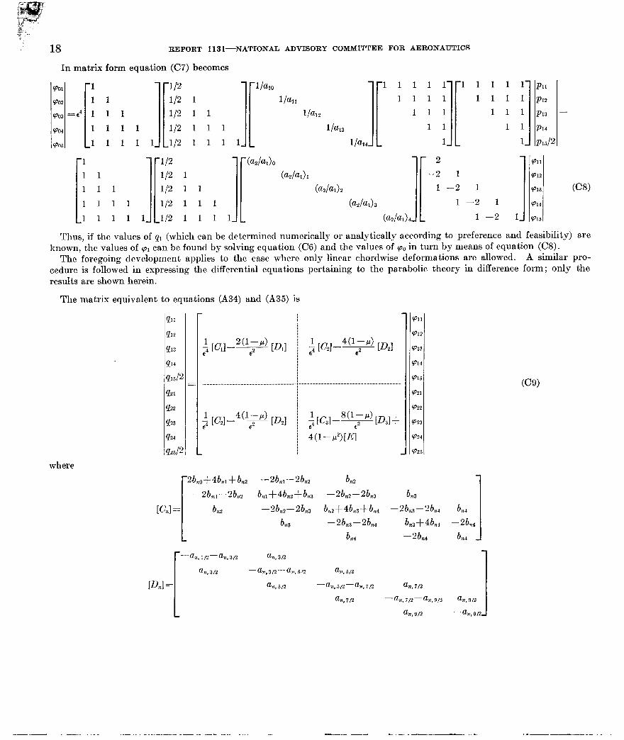
In matrix form equation (CT) becomes
(001
Qo2 1 1 (PO3 =e4 1 1 1 Qo4
i 1
1 1 1 1 QM 1 1 1 1 1
I 1 1 1 1 1 1 1 1 1 1 1 1 1 1 1.
Thus, if the values c
(u2lf-40 (011
b2l& Q12
(a2la1>2 (013 (-9
b2/&)3 Q14
l/2 1 1 1 1 @2hL Ql.5
)f pl (which can be determined numerically or analytically according to preference and feasibility) are known, the values of (ol can be found by solving equation (CS) and the values of Q. in turn by means of equation ((28).
The foregoing development applies to the case where only linear chordwise deformations are allowed. A similar pro- cedure is followed in expressing the differential equations pertaining t.o the parabolic theory in difference form; only the results are shown herein.
The matrix equivalent to equations (A34) and (A35) is
$1
PI2
!A3
a4
!I&
9121
!L=
%3
!b4 P25/2
$ [CJ-4v [D2]
$ w21 -%$!d [D2]
$ W31 -v [D31 t
4(1-p2)[E]
where
r2b,o+4b,~+b,, -2b,,--2bnz b n2
(PII
(PI?
(PIP
Q14
Q15
Q21
Q22
Q23
Q24
Q25
1 -2bb,,-2bb,, b,l$4b,zfb,,3 --zb,,--zb,, b n3
[Cnl= bn2 -2b,,--zb,L, b,,+4b,,+b,, -2bn,-2b,,, bn4
Pnl =
1 b 723 -2bn3-2bn4 b,,S4bn, -2bn, b n4 --2L b n4
-%1/2-%3/2 %l,3I?
%I. 312 -u,312-a,r,5r2 G. 512
an, 5,2 -G7,512-“~,i12 a,, il2
f-h?, 712 -%zs i/2-“n, 912 %I, 912
G?, 912 --an,9/2 1
Kw
--... _ _ .__- . _..-..- .._ _ - ._ .-- - _.. _. . ._. -.-.--_- . ..-.- _. .-. . ---.-..--. -. ._.---- ..__..... -

DEFLECTION AND STRESS ANALYSIS OF THIN SOLID WINGS OF ARBITRARY PLAN FORM
Ia=
a11
[
a12
= a13
al4
a!
and ~1 and q2 are the.right-haqd sides of equations. (A34) and (A35), respectively; that is, ,.-.
With ~1 and cpz known, (o. can be obtained by use of equation (A33)
901
cpoz 1 =
PO3
‘PO4
(PO.5
[ 1
1
1
1
1
1 1 Ii 112 l/2 l/2 l/2 l/2 1 1 1 1 1 1 1 1 1 1. [
l/a*0 l/all
E4 lbl2 l/al3
1 /a14.
Ii 1 1 1 1 1 1
(a&Jo
(aphI) 1
(a21aJ 3
b2/ad3
(a21al) 4.
(a3bJo
b3h) 1
(a3bd 2
(a31aJ 3
(a3bJ
1
It should bc noted that, as can be expected, the matrix equations (CS) and (CS) are merely special cases of equations (C9) and (ClO), respectively. In addition, the square matrices in equations (CS) and (C9) are symmetric, a result that is consistent with the fact that the differential equations under consideration are self-adjoint.
In the beginning of this appendix the assumption was made that the functions involved in the differential equations are continuous and nonsingular. The difference solution, how- ever, may be adequate for some cases in which this assump- tion is not strictly correct. For instance, the deflections of a plate with a discontinuous stiffness distribution could con- ceivably be not very different from the deflections of a plate
cpll
$713 -
4714
(P15
(P21 9721
cPas cp22
(P23 -2pe2 (P23
(P24 (P24
(P25 9925
1 1 1 I[ 1 1 I[ 1 1 1 1 1 1 1 1’ 1’
1 1 1 1 1 1 1 1 1 1 1 1
1 1 1 1 1 1 1 1 1 1
1 1 1 1 1 1 1 1
1 1 1, 1, 1 PII
PI2
PI3 - PI4
Pd2
(ClO)
: .I I
with a continuous stifl’ness distribution closely approximating the discontinuous distribution except in the neighborhood of the discontinuity. The results yielded by the difference solu- tion in this case would be those associated with the continuous stiffness distribution. The number of stations may have to be increased, however, in order to minimize the inaccuracy introduced by the discontinuity or, in other cases, by a singularity. The case of the symmetrical double-wedge air- foil section, constant-thickness-ratio delta plate, discussed in the body of this report, is an example of a treatment of a singularity. In this case, although the solution is singular, adequate accuracy is obtained by the difference solution if ten equal intervals are used.

APPENDIX D DEFLECTION AND STRESS EXPERIMENTS ON SOME TRIANGULAR CANTILEVER PLATES
Test specimens.-The specimens tested were: (1) a 45O right-triangular plate clamped along one leg and (2) a 60’ right-triangular plate clamped along the longer leg. Each specimen, cut from 24S-T4 aluminum-alloy sheet of 0.250- inch thickness, had a length perpendicular to the clamped edge of 30 inches.
Method of testing---Figure 12, a photograph of the test setup, shows the methods of clamping, loading, and measure- ment of deflections. A l,OOO,OOO-pound clamping load (held constant during the test) was applied to the root area of each specimen and a uniform load of 0.204 psi was applied by 2-inch washers giving a tip deflection in each case of approx- imately $ inch.
The deflections were measured by dial gages placed at the points indicated in figures 2 and 3.
Stresses were obtained from the 45” specimen only. On this specimen, 13 resistance-wire rosette strain gages were placed at the points indicated in figure 5. The plate was loaded with 2-inch washers in four increments of 0.0847 psi per increment and the maximum tip deflection was 1.13 inches. Readings of all the strain gages were recorded at each increment of loading.
Analysis and discussion of data.-The deflection w was plotted in figures 2 and 3 in terms of the nondimensional
FIQURE 12.-Deflection test setup of the 45’ delta plate under uniform load.
20
parameter wD/pF, in which the elastic constants were taken
as E=10.6X10⁶ psi and p=$ It was found that the dial-
gage forces reduced the tip deflection of the plate by approx- imately 2 percent; however, since this error is of the same order of magnitude as that in the material properties and from other sources, no corrections are made in the results presented.
The readings of each of the 39 individual strain gages were plotted against load, and the slope of each of the resulting linear curves was taken as the average strain per unit load of the individual gage. The principal stresses were then calculated and plotted in figure 5 in terms of the nondimen- sional parameter (rt2Jp12.
REFERENCES
1. Fung, Yuan-Cheng: Theoretical and Experimental Effect of Sweep Upon Stress and Deflection Distribution in Aircraft Wings of High Solidity. Part 2. Stress and Deflection Analysis of Swept Plates. AF TR No. 5761, Part 2, Air Materiel Command, U. S. Air Force, Feb. 1950.
2. Williams, M. L.: Theoretical and Experimental Effect of Sweep Upon the Stress and Deflection Distribution in Aircraft Wings of High Solidity. Part 6. The Plate Problem for a Cantilever Sector of Uniform Thickness. AF TR No. 5761, Part 6, Air Materiel Command, U. S. Air Force, Nov. 1950.
3. Sham, F. S.: The Approximate Deflection of Thin Flat Triangular Cantilever Plates Subjected to Uniform Normal Load. Rep. SM. 154, Aero. Res. Lab. (Melbourne), June 1950.
4. Zahorski, A.: Mathematical Analysis of Cantilever Plates. Rep. i”o. GM-313, Northrop Aircraft, Inc., Jan. 1949.
5. Benson, Arthur S., and Siles, Alfred S.: Bending and Torsion of a Rhomboidal Cantilever Plate. Tech. Rep. No. 2, Air Forces Contract W33-038 Ac-16697, Guggenheim Aero. Lab., Stanford Univ., Oct. 15, 1948. (Also available as AF TR No. 5795, Part I, Air Materiel Command, U. S. Air Force, May 1950.)
6. Reissner, Eric, and Stein, Manuel: Torsion and Transverse Bending of Cantilever Plates. NACA TN 2369, 1951.
7. Schiirch, H.: Zur Statik VOII diinnen Flugzeug-Tragfliichen. Mitt. Sr. 2, Inst. fiir Flugzeugstatik und Flugzeugbau an der E. T. H., Leemann (Ziirich), 1950.
8. Hrebec, G. If.: Theoretical and Experimental Effect of Sweep Upon the Stress and Deflect,ion Distribution in Aircraft Wings of High Solidity. Part, 8. Some Experimental Data on the Deflection and Root Stresses in a Cantilever Triangular Plate of Constant Thickness With Varying Trailing Edge Sweep Angle. AF TR Ko. 5761, Part 8, Air Materiel Command, U. S. Air Force, Nov. 1950.
9. Timoshenko, S.: Theory of Elast,ic St,ability. McGraw-Hill Book Co., Inc., 1936, ch. VI.