report 1159 - ntrs.nasa.gov
TRANSCRIPT
REPORT 1159
IMPINGEMENT OF WATER DROPLETS ON WEDGES AND DOUBLE-WEDGE AIRFOILSAT SUPERSONIC SPEEDS ‘
.By JOHNS. L%RAFINI
SUMMARY
An analyticalsoluttin h prawntidfor the equution-sof motionoj watir dropleti impin@ng on a wedge in a twodimewi.ondmpersoni-cffowjiefd with an attuckd dock wave. T’lwclosed-form solwhlmyields analytical qmmi.on3 for the equation ofthe droplet trajeeton], h 10CUJrate of impingement and the im-pingement ndocity at any point on the wedge swface, and theioial rate of impingement. The analytical tzzprewimw areutilized in the ddemninutionoj the impingenwni of water drop-kts on tiujorward surfaca of symmetricaldouble-wedgeairfoilsin supersonicjbwfiekk with attacheddock warn%.
I’or a wedge, the rtwdta provide infornun$on on the efects ofthe droplet 8ize, L&?f?ce-stream liach number, the 8emiupt3augle, and the premwrealtitude. For the o?ould+wedgeairfoil,additional calcutiwns provide information on the e$ect of aix-[oi[ thichnemratio, chordlength, and angle of aituck.
The resuh!xjor the symnutrical double-w~dgeairfoi-1are akocorreltid in term of the toi!ulco.?leclionefmkncy m afurm!ionoj a relative mod#ied inertia parameter. Tlw reswlls are pre-sentedjor the fohzoing range$ of cariabk: free+t$eum i3tatictemperature,@OOto 460° R; dropletdiumakr,1?tQ100 microns;free-stieam Mach number, 1.1 to $.0; wmiapex an@e for thewedge, 1.14° to 7.97°, and camxponding double-wedge-airfm”lthicknm-t.o-chrd ratw, 0.0$ to 0.14; pressure ai%%uie, seaievd to $0,000feet; and chordLength,1 to %Ofeet.
INTRODUCTION
The problem of ice prevention on aircraft flying at sub-sonic speeds up to critical M&ch numbers has been a subjectof considerable study and research by the NACA. The recentadvent of aircraft flying at transonic and supersonic speedslIas required an extension of these icing studies. That anicing problem exists in the transonic and supersonic speedrange is verjfied in reference 1,which shows by an analyticalinvestigation with experimental confirmation that diamondor symmetrical doubkwwlge airfoils are subject to possibleicing at flight Mach numbers as high as 1.4. A similar re-SUIt is expected for other airfoil shapes being considered foruse ruttransom”c and supersonic flight speeds.
In conducting research on the problem of ice preventionon aircraft and missiles, regardless of the magnitude of theflight speed, it is essential that the impingement of clouddroplets on airfoils and other aerodynamic bodies be deter-mined either by theoretical calculations or experiment. The
impingement variables that must.be determined are the totaIwater catch, the extent of impingement, and the rate of im-pingement,per unit area of body surfam. These variablesean be determined analytically from calculations of the cloud-droplet trajectories obtained for the various aerodynamicbodies. Investigators have reported the results of studies ofcloud-droplet trajectories about right-circular cylinders (refs.2 to 5) and about airfoils (refs. 6 to 9) immersed in an in-compressible fluid. An evaluation of the effect of compres-
,sibility on the droplet trajectories about cylindem and airfoikup to the critical flight Mach number is presented in refer-ence 10.
At present, little information exists on the impingementof droplets on aerodynamic bodies in a supersonic air stream.The concentration of past effort on problems of impingementon airfoils at subsonic flight speeds and the present lack ofconvenient and rapid means for obtaining the rotationalflow fields about airfoils at supersonic speeda are possibleexplanations for the scarcity of trajectory calculations forthe supe~onic region. An initial contribution to the solu-tion of the over-all problem of impingement of water dropletson aerodpamic bodies at superaonk speeds is given inreference 11, which presents an analysis of the water-interception characteristics of a“wedgein asupersonicflow field.
The present report extends the analysis of reference 11and further presents an extensive study of the impingementof water droplets on two-dimensional wedges and double-wedge airfoils for supersonic flight speeds that remdt inattaohed shock waves and constant veloeity fields behind theshock waves. For the wedge angles and double-wedge-airfoil thickness ratios considered herein, the shock-wave-attachment Mach number varies from a value slightlygreater than 1 to about 1.4. The method employed is basedon an”analyticrd solution of the equations of motion by meansof a closed-form integration. The closed-form solutionyields analytical expressions for the equation of the trajec-tories, the local impingement efficiencies, the velocity at anypoint on the trajectory, and the total rate of impingement.This solution is made possible by the use of an empiricalrelation for the drag coefEcients for spheres that gives a goodapproximation of the experimental drag coefficients.
The results of calculations for the rate, the extent, and thedistribution of impingement of water droplets on wedgesand symmetrical double-wedge airfoils are presented herein.
ISu- NAOA TN Z971,%npbwmmtofWaterDroP1etsmIWeilgmandDiamondAfrfoilsatSm.WSOnfoSweds,”byJohnS.Swa13ni,19S9.%
.— .- . . ..— ————— .—— . .
86 REPORT 115~NATIONAL ADVISORY CObIMITTEE FOR AERONAUTICS
The ranges of variables included for the wedge are: fiee-stream static temperature, 420°, 440°, and 460° R; ‘dropletdiameter, 2 to 100 microns; free-stream Mach number, 1.1to 2.o; tangent of the semiapex angle, O.O2 to 0.14; andpressure altitude, sea level, 15,000, and 30,000 feet. Theranges of variables for the double-wedge airfoil are the sameas those for the wedge, and the additional variables for thasymmetrical double-wedge airfoil range from 0.02 to 0.14 forthe thickness ratio and from 1 to 20 feet for the chord length.
The work reported. herein was performed at the NACALewis laboratory in the spring and summer of 1952.
ANALYSISSTATEMENTOFPROBLEM
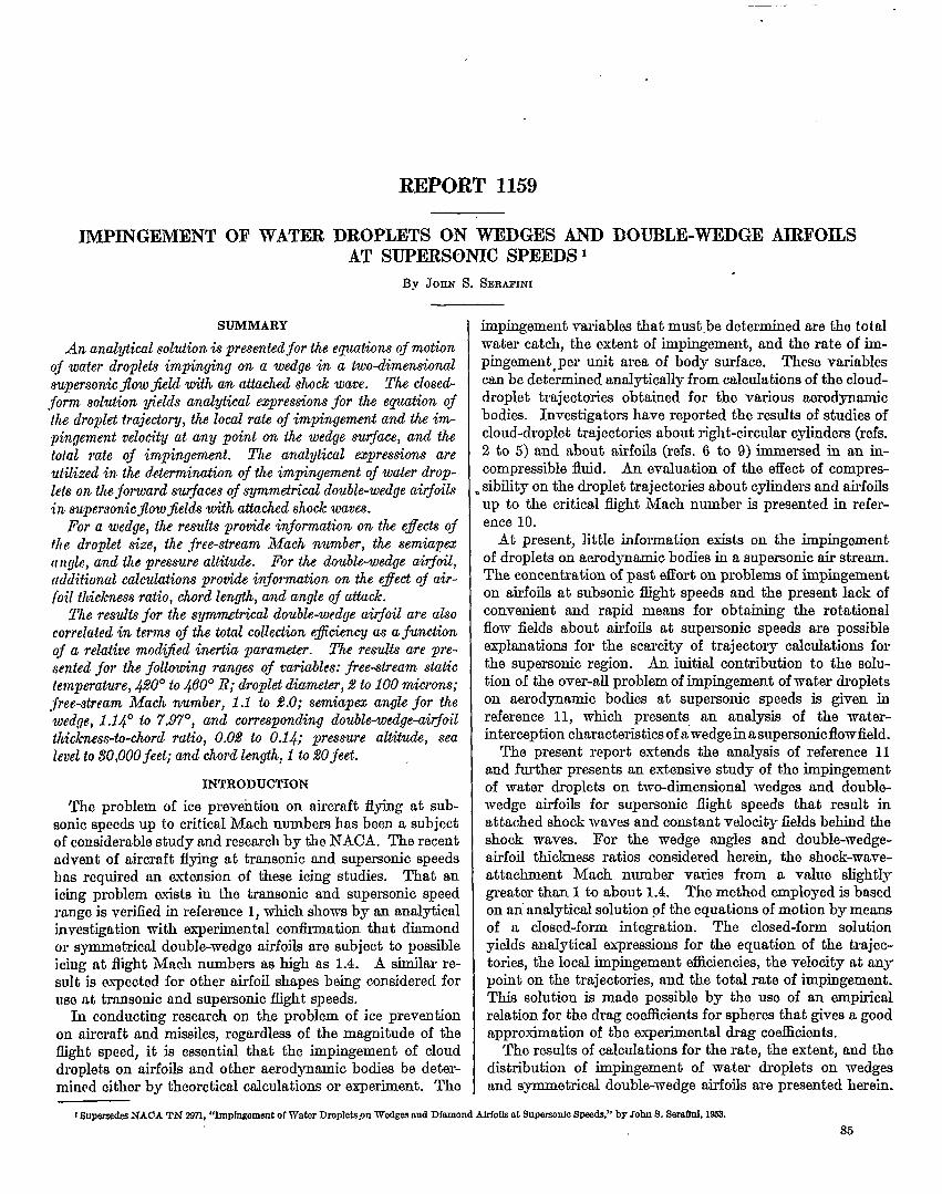
The solution of the problem of impingement of waterdroplets on a two-dimensional wedge at supersonic speedswith an attached shock wave is not as difEcUlt’ as that forthe impingement t on various airfoils at low subsonic speeds.For the wedge at supersonic speeds with an attached shockwave, the air velocity everywhere ahead of the shock waveis constant and equal to the free-slru air velocity VI(fig. 1). The air velocity behind the shock wave Vz is alsoeverywhere constant and parallel to the wedge surface. AUthe droplets have the same initial velocity (that of the ties-”stream air veloci~), and their trajectories are exactly co-incident with the air streamlines upstream of the shockwave.All water droplets of a given size are subjected to identical
At f=O
ah-velocity fields, which in turn produce identical forcesystems downstream of the shock wave, irrespective of thopoint aIong the shock wave where the droplets cross thowave. It follows, therefore, that, for dropIeta of a givensize, all the trajectories in a given problem are identical withrespect to the point where the droplet crosses the shockwave.
By adopting a frame of reference that moves at the con-stant velocity of the air V2 downstream of the shock wave,the problem of the droplet motion is reduced to the stilkirproblem, defied as the- determination of the motion of odroplet that, having an initial velocity, is projected intoquiescent air. Hence, relative to the moving frame of refer-ence, the initial velocity of the droplet upon crossing theshock wave is equal to the vectorial difference of the free-stream air velocity VI and the air velocity V2downstream ofthe shock wave. Adoption of the frame of referanco movingwith a constant velocity reduces the problem from tho solu-tiori of two simultaneous nonlinear second-order differentialequations in the fixed wordinate system to the solution of asingle nonlinear second+rder diilerential equation in themoving coordinate system. AX any given instant, the drop-let displacement relative to the point of intersection with theshock wave in the fixed frame of reference is obtainod byadding vectorially the droplet displacement within the mov-ing frame of reference to the displacement of the movingframe of reference for the same increment of time.
At t=f
.-L
Dro@tmjectcq
L- T
Fmmm l.-%hematio diagram of water-droplet trajedory for wclge in supersotio flow with attaohed shock wave,

—
This
IMPINGEMENT OF WATER DROPIXWS ON WEDGES AND
general method was used m reference 11, where theone second -order differential equation represauting the drop-let motion relative to the air velocity behind the shock wavewas integrated graphically. However, it is possible toobtoin a completely analytical solution by means of a closed-form integration without resorting to the use of numericalintegrations or analog computing equipment, if an empiricalrelation is assumed for the drag coefficient as a function of theReynolds number of the droplet relative to the air. It willIm shown that this closed-form integration of the still-airproblem when applied to the wedge in supersonic flow withattached shock wave yields the equations for the trajectoriesof the water droplets and the droplet velocities at any pointon the trajectories and makes available relations for therates of total water impingement and the local rates of waterimpingement along the wedge surface. Furthermore, it isshown that these equations can also be readily applied to thedetmmination of the droplet impingement on a double-wedgeairfoil in supersonic flow with attached shock wave.
Three of the usual assumptions made in the previous in-vestigations on impingement at subsonic speeds and alsoreqw”red for this investigation are (1) the water droplets arealways spherical and do not change in size, (2) the force ofgravity on the droplet maybe neglected in comparison withthe drag forces, and (3) the drag of the air on the droplet isthat of a viscous incompressible fluid. Here it is additionallyawwned that (4) the two-dimensional supersonic flow fieldabout the wedge is frictions except within the infinitesi-Iually thin attached shock wave, (5) no condensation shockoccurs and no change in phase occurs as the ww%r dropletstravmse the oblique shock wave, and (6) the unbalance ofthe forces on the water droplet from the instant it enters theshock wave until it emerges from the shock wave can be neg-lected in the calculation of the trajectories.
EQUATIONOFDROPLETMOTIONINMOVINGRBFEEENCEFRAME
The velocity of the droplet in the moving frame of refer-ence is
V=lv.–v,l (1)
where ~,i is the droplet velocity with respect to the fixed
frame of referenge, .~d ~g is the air velocity downs&& ofthe attached shock wave also with respect to the tiedframe of reference (fig. 1). In the frame of reference moving
with the velocity Vz, the statement of Newtcn’s lam of mo-tion for the water droplet becomes
from which
dU 3 pf u~—=–g-----i%dt
(2)
(3)
(A complete list of symbols is given in appendis A.)Equation (3) is the differential equation of motion of a
droplet projected with an initial velocity into a region ofquiescent air (the so-called still-air problem). The shockwave is considered to be a surface of discontinuity from which
308GG&6*7
DOUBLE-WED(2I3 AIRFOILS AT SUPERSONIC SPEEIDS
the droplets emerge with a velocity V1. In this caseinitial velocity of the droplet is
U,=p,-v,]
which is the magnitude of the vector difhrence of the
w
the
(4)
air-velocity vectors ~pstream and downstream of the attachedshock wave. As can be shown from consideration of thecontinuity equation and the equation for conservation ofmomentum across the oblique shock wave, the velocity vec-
tor ~t is normal to the shock wave. At any subsequent
instant of time, the felative droplet veloci@ vector ~ retainsthe same angular orientation to the shock wave and changesonly in magnitude.
In reference 11 the solution of equation (3) is obtained bynumerical integration. The result obtained in this mannermakes it necessary to use a graphi@ procedure in determin-ing the trajectories and the local rates of impingement.However, an analytical solution of equation (2), which elimi-nates the graphical procedure, can be obtained if the esperi-rnental values of the drag coefficient CD are expressed in Qfunction involving the Reynolds number Re,. The relationis
(5)
where e and m are the empirical constants. This empiricalrelation is a valid approximation in the range of Reynoldsnumbers to which cloud droplets are subjected in trajecto~calculations. Substitution of the expression for CD (eq. (5))in equation (3) results in the expresion
%=%=-% 5[’+’(%31 ‘6)where the 19cd relative Reynolds number Re,=2pJJa/P~.The displacement of the water droplet in the moving frameof reference z is measured from the air streamline that inter-sects the shock wave at the point where the water dropletenters the ah-flow field downstream of the @sock wave.The closed-form integration of the ditlerential equation (6)is presented in appendix B. . The use of 2/3 for the exponent~ and 0.158 for the value of the empirical constant ● in equa-tion (5) yields an empirical curve for the diag coefficient asa function of the local Reynolds numbers that approximatesvery w-all the variation of the experimental values of thedrag coefficient in the range of Reynolds numbers from 0.5to 500. The value of 2/3 for the exponent m also facilitatesthe closed-foma integration of the d.ifTerential equation ofmotion. In figure 2 a graph of the empirical relation ispresented, along with the drag-coefficient data of references4 and 12.
The results of the integration are given by the followingequations:
J(Re,, t-’/3c:1+i)e’– l–b-’ 4(Re’-t-v3’-1+1)e1-11
(7)

—
Ss REPORT 115&NATIONAL
u=—Re:c3/’ ‘(R’’+ ’-’’86-’+1) “-1]-3’2
and
— —
ADvrsoRY coMMTI’PEIIl FOR AERONAU!MCS
(8)
(9)
where
The intermediate steps of integration are~ven in appendix B.Equations (7) and (8) give, respectively, the diapIacement
and the veIocity of the droplet at any instant in the movingframe of reference. The displacement of the droplet withrespect to the point where it crosses the ~ock wave can beobtained by a vectorial addition of the displacement x andthe displacement of tlm moving reference frame in the cor-
responding time interval. The droplet veloci~ V&relativeto the fixed frame of reference must also be obtained by the
vectorial addition of ~ (eq. (8)) and ~~. Equation (9)
gives the maximum value of x obtained as the time of trav~lin the air-flow field downstream of the shock waveapproaches infinity. The sign.iiicance of this quantity wiIIbe discussed in subsequent sections.
RELATIONSREQUIREDFORAPPLICATIONOF CLOSED.FOBMSOLUTIONTO OBTAINDROPLETMOTIONANDIMPINGEMENTIN FIXED
REFEEENCEFRAME
Impingement on wedges.—For a problem of given aero-dynamic conditions, the trajectories of all the water dropletsof a given size are identical when the points where the droplottrajectories intersect the shock wave are superimposed.This unique characteristic of the water-droplet trajectoriesabout a wedge in supersonic flow with an attached obliquoshock wave is the result of two constant velocity fields, onoupstream and one downstream of the shock wave. There-fore, only one set of equations for a single trajectory is neces-sary to calculate the impingement parametem for a specifiedproblem, including a given droplet size. The values of thoinitial relative velocity Uf, the ~tial Reynolds numberRq,,, and the density ratio ptJti are needed for substitutionin the closed-form solution of the equations of droplet motion.These values can be obtained from information available in ,reference 13 and from the use of simple algebraic and trigo-nometric relations for given values of the free-stream statictemperature h, the droplet diameter d, the free-stream iMachnumber Ml, the angle of surface inclination to the free-strcmndirection u, and the free-stream static pressure PI. ThesoreIations result in the following expressions for the initialrelative velocity and the initial relative Reynolds number:
20
10
6
3
2L
1
-- I
~ Iv .6= rrc1
I
1:1
~,/ I I I I I I I I I
.3
.2
J
I I I 1 I I I II
.06
I I I I I I I I I I I I I 1 I I 1 I I I I I I t I I I
/ A
I /- Q 1 1 1 1 I 1 1 1 4r1
/
/ ‘
J)3:I T I I 1 I I I I I I I I I I I I I I I I I I I 1 I 1 1 1 1 I t I I I 1JI 10 100 1000
Droplet Reynoldsnumber,Rer
l?mURF32.—Comparimn of empirical relation for drag coefficient as function of droplet Reynolds number with experimental value%
Q@=l+ o.158Rar91324

IMPINGEMENT OF WATER DROPLETS ON WEDGES AND DOUBIJZ-WEDG13 AIRFOILS AT SUPERSONIC SPEEDS 89
U:=luil= V141+Q2—2Q Cosu= Vw (lo)
and—
(11)
A convenient form of the solution for the impingement ona wedge or the front half of a double-wedge airfoil is obtainedif S is defined as the distance to the point of impingementmeasured from the leading edge for a water droplet thatenters the flow field behind the shodc wave at a distance rabove the leading edge (fig. 1). The uuique relation betweenS rmd t in a given problem for droplets of the same size isquite readily determined by considering the displacement ofthe water droplets as the vectorial sum of the displacementof the water droplet relative to the moving frame of referenceand the displacement of the moving reference frame relativeto a fixed frame of reference (referred to wedge). Since themoving referenm frame has a velocity equal to the air velocityVz, which is constant in magnitude and parallel to the wedgesurface, only the droplet travel in the moving reference frameincludes the component of droplot travel representing theupprorwh of the water droplet to the wedge surface. For awater droplet starting from point A and impinging on thewedge surface at point D (fig. 1), the displacement of themoving reference frame (= Vzt, -where t is zero at point A) isgiven by the displacement vector ~ equal to ~, and thedroplet motion in the moving frame of reference is given bytlm displacement vector ~ equal to ~. Therefore, rela-tive to the starting point at A (fig. 1), the displacement ofthe water droplet to the point of impingement at D isobviously equal i% ~ +~ or to ~+~. From figure 1,the displacement of the water droplet at the point of impinge-mentt D, measured from the leading edge at E, is given byadding the vector ~ to the displacement vector from thestarting point A; and the displacement of the droplet at Dreferred to the leading edge is
s=lml=lm+m+ml=] m+m]=]ml+]m]=f+~’
(12)
whero : is the magnitude of the displacement vector ~,and g’ (= VJ) is the magnitude of the displacement vector~D (the displacement of the moving frame of reference).
The values of ~ and fare obtained in terms of x, the distanmof travel in the moving reference ihme, from simple trigo-nometric identities involving the various angles shown infigure 1:
~=z sine tan (v-l-u) , (13)
where x is given by equation (7); v by
‘=sh-’[@h”H(13a)
andf=z sec (v+u) (14)
Substitution of equation (14) into equation (12) for the sur-face distance to the point of impingement yields the followingequation:
S=x sec(v+u)+V, ~2 T (15)
Since z is a function of ~ in equations (13) and (15), theexpressions for { and S, respectively, are functions of ~.However, since ~ cannot be eliminated from equations (13)and (15),5’cannot be obtained explicitly as a function of ~.Nevertheless, the curves of ~, the initial displacement of thewater-droplet trajectory from the leading edge normal tothe free-stream direction, against S’, the distance to the pointof impingement of the stated water-droplet trajectory, canbe obtained by substitution of the same set of values for rin the expressions for ~ and S.
An analytical expression for the local impingementefficiency can be obtained horn the preceding expressionsfor ~ and S. The local impingement efficiency 13is defiedby the expression
dc
(16)
dr
where A~ is the ditlerence in the initial displacements of twowater droplets having very nearly equal initial displacements,and Ml is the small increment of wedge surface between thopoints of impingement of the two water droplets. Differen-tiating ~ and S with respect to r and performing the divisionindicated by equation (16)yield the following expressionfor D: .
wherenl=sin e tan (V+u) (18a)
m=sec. (v+u) (lSb)
(18C)
Since P and S both are functions of ~, the local impingementefficiency ~ at any point on the wedge surface is determinedby using the same value of r in equations (17) and (15). Thevalue of p that exists as the point of impingement of thewater droplet on the wedge surface approaches the leadingedge as a limit (S’+) is given by the following:
.
The magnitude and direction of the droplet velocity at thepoint of impingement V~,m (relative to the fixed frame ofreference) can also be easily obtained at any point on thewedge surface as
()Ui.* 2+2Q. ~ Cos (P+ u) (20)
[
UimKf==U— U;m=U—SiIl-l — sin (V+u)
V4 i. 1(21)
where Kis the angle between the free-stream velocity vector

.—— — . ----
90 REPORT 115&NATIONAL ADVISORY COMMJTKEE FOR AERONAUTICS
shock Wve Eqow”onzcw
AMl
D
/.
‘y\ \\\ ‘\\\\\ \\
/\ \\
\Shociwove
(0)
Ex+ansion zqe
Expcnsion zone
Shock wove Exponsion ZOIW
(b)
Exgo&on zcm.
‘L /“/“
// Exponsion zone
// ,0’
x,/ ,,’-’
/:-- /// ,/ ‘
M,A&N ,+-
Shoci wove Exponsic+i zme
(c)
V, and the droplebvelocity vector ~~, rmd u’ is the rmglo
between the droplet-velocity vector ~~ and the air-velocity
vector T*. In equations (2o) and (2I) for a given tmjectoly, “Vl, Q, w, Ui, v, and u are constants. Therefore, for o giventrajecto~, V%,= and Kti are functions only of U (eq. (8)),which is in turn a function of r, the dimensionless timevariable.
Impingement on symmetrical double-wedge airfoils,—The impingement on a double-wedge airfoil maybe obtainedfrom the solution to the problem of impingement on a wedgeas presented heretofore. In this report, the double-wedgoairfoil considered is symmetrical, the maximum thickne-moccur@g at 50 percent of chord (fig. 3). At zero angle ofattack, the impingement on a double-wedge airfoil will belimited to the region from the leading edge to the shoulderat 50 percent of chord. The solution for impingement on awedge surface having a given semiapex angle u (the angle ofinclination of either wedge surface to the free-stream direc-tion) can also be used as the solution for a double-wedge air-foil where the thiclmess ratio is equal to tan u, the tangent ofthe semiapex angle, and where the droplet size and otherparameters of the problem are the same aa for the wedge.Therefore, the values of the local impingement efficiencies9 and L?,at any given point on the surface will be identicalfor both the w-edge and the double-wedge airfoil at zero angloof attack under the aforementioned similarity of conditions.
The solution for the impingement on the double-wedgeairfoil at angle of attack can also be obtained from thesolution for impingement on a wedge as for the case of thedouble-wedge airfoil at zero angle of attack. When thesymmetrical double-wedge airfoil is at angle of attack a,the angle of inclination of its forward upper surfaco to thefree-stream direction is equal to u– a and that of the forwardlower surface is equal to U+ a. Therefore, the solution tothe impingement on the upper and lower surfaces of thedouble-wedge airfoil is obtained $om the solutions forimpingement on wedg= having the redeiined semiapex anglesof u— a and U+ a, respectively, where the droplet size andother parameters of the problem are kept the same. I?orthe double-wedge airfoils at angles of attack having tangentsequal to or greater than the thiclmess ratio, the wmtwdroplete will not impinge on the upper surface. At anglwof attack having tangents greater than the thickness ratio,some water droplets may impinge on the lower surfacebeyond 50 percent of chord. These three conditions are il-lustrated schematically in figure 3. For a<tan-’(T/c), theimpingement occurs on surfaces AC and A B;for a= tan-l (T/c),impingement occurs only on surface AC; for a>tan- 1(T/c),impingemezit occurs on lower surface AC and may occuron lower surface CD. However, the condition wherea>tan- 1(T/c) is not considered herein, since the solutionpresented in this report is not valid for the determination
(a) Angle of attack a<tan-l(T/c).(b) Angle of attack a=tan-’(T/c).(c) Angle of attack a>tan-’(T/c).
~GURZ &-8chematia diagram of symmetrical doubkvedge airfoil atangle of attack in superaonio flow with attached shook wave.
IMPINGEMENT OF WATER DROPIJ3TS ON WEDGES AND DOUBIJI-WEDGE AIRFOILS AT SUPERSONIC SPEEDS 91
of trajectories of droplets impinging on the surface beyondthe shoulder or .50 percent of chord of the doubl~wedgeairfoil (surfaces BD or CD), where a portion of the trajectorimis within the aspansion zone emanating from the shoulder.
RESULTS AND DISCUSSION
I?rom the equations presented in the previous section andin nppendix B, the impingement of water droplets on a wedgein a supersonic flow field with an attached shock wave canbe calculated over a range of free-stream conditions, wedgeanglea, and droplet sizes. As has been indicated previously,the impingement characteristics of a double-wedge airfoil(fit zero angle of attack and also for small values of angle ofattack) can readily be determined from the impingement onwedges for similar conditions. The results for the wedgeand the double-wedge airfoil are presented and discussedseparately. A comparison of the total collection eiliciencynnd the water impingement rate at zero angle of attack for adouble-wedge airfoil with those for an NACA 0006-64nirfoil is presented in appendix C.
WEDGE
Zooal impingement efflcienoy.-The rate of water impinge-ment on a local area of wedge or airfoil surface is proportionalto L dimensionless term P, the local impingement efficiency.The local rate of water impingement in pounds per hourper square foot is
WP=0.3296V,W13
where 19is defined in equation (16). The local impingementefficiency, when given as a function of the surface distanceof the wedge, allows tho determination of the local rate ofimpingement of water droplets at any point on the surface,the total impingement of water droplets on the entire sur-face or any given portion of the surface, and the extent of
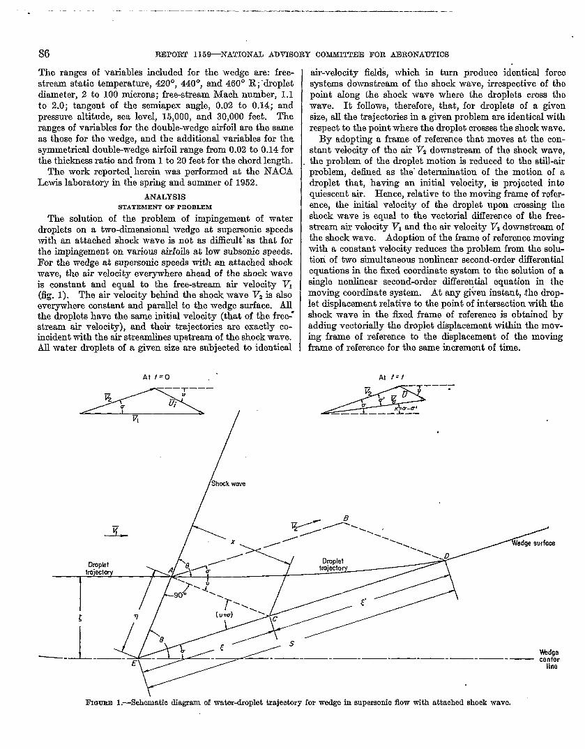
impingement on the surface. The local impingementefficiency B is related to a point at a given distance S onthe wedge surface in equations (15), (17), and (19) by thedimensionless time variable ~, which is common to all threecxprass.ions. The variation of P with S is presented infigure 4 for an extensive range of free-stream conditions,semiapex angles, and droplet sizes. The value of P at theleading edge (S40) is the sine of the semiapm angle (sin u);and as S increases, the value of p decreases rapidly and ap-proaches the value of zero asymptotically as S approachesinfinity. However, it is to be noted that negligibly smallvalues of 13@ = 1 percent of & for the wedge) are attainedat large but finite values of S.
The curves of 19as a function of S presented in figure 4are those of an idealized situation. The assumed two-dimensional supersonic flow field about the wedge does notaccount for a stagnation point that must exist at the leadingedge of the wedge, regardless of the sharpness of tho leadingedge. ID addition, the leading edges of wedges and double-wedge airfoils might be considered to be somewhat roundedwhen subjected to considerable m-cation. Therefore,it is reasonable to assume that very near the lead@ edge(S+0) the value of 6 would actually be greater than thecalculated value of # at the given distance S. However,this should have a negligible effect on the rest of the p curveand also on the total impingement on the wedge, since theeffect ‘of a stagnation point would bo limited to n verysmall region about the leading edge.
For S approaching very large values, the calculated valuesof B probably di.tier somewhat horn actual values obtainedin flight, because the analytical solution of the present reportdoes not consider the existence of the boundary layer on thewedge surface. Since the boundary-layer thickness increaseswith the surface distance along the wedge, droplets that im-
.020
.016
Q~-C
.: .012
~
3.:,008.-Z8-1 \
004 L
(a)
0 I 2 3Dis~an-ce slang ~rfcce of we~e (from Ieoa;ng edge), ~ ft
9 [0 II 12
(a) Effect of prewmrealtitude. Droplet diameter, 20 mfarona;free-stream Maoh number, 1.4; tangent of serniapexangle, 0.02.
FIGURE4.—Local frnpingementefficiency on wedge as function of distance along surface. Free+tream static temperature, 440° K

—.—..— .
92 REPORT 115P NATIONAL ADVISORY COhmfMT’EE FOR AERONAUTICS
pinge at large distancw from the leading edge actually wouldham traveled through the boundary layer for some non-negligible interval of time. However, only a very smallfraction of the total water droplets of a given size impingeunder this condition, and for large values of S the values of~ are negligibly small. For example (fig. 4 (a)), such wouldbe the case for values of S greater than 8 or 9 feet, w-here/3<0.0002 m compared with 19,=0.020.
A prelimhmry survey disclosed a negligible’ effect of thefree-stream static temperature on the local impingementefficiency as a function of the surface distance along thewedge (II qytinst S).. Values of P and corresponding valuesof S were calculated for free-stream static temperatures of420°, 440°, and 460° R, droplet diameter of 20 microns, free-strenm Mach number of 1.3, tangent of the semiapex angleof 0.06, and pressure altitude of 15,000 feet. The values ofp for tlm free-tream static temperatures of 420° and 460° Rare within 1 percent of the values of/3 at 440° R. Since thesecalculations show that curves of ~ against S for the threevrducs of free-stream static temperature form practically asingle curve when plotted to the usual scales, no figure ispresented to illustmte the effect of free-stremn static tem-porahu-e on impingement. Furthermore, the results includedherein, which are calculated for a free-stream static temper-ature of 440° R, may be used in the range of temperaturefrom 420° to 460° R or possibly an even greater range.
The effect of the free-stream static pressure on the localimpingement efficiency as a function of the surface distancealong the wedge is presented in figure 4 (a) for pressurealtitudes of sea level, 15,000, and 30,000 feet. Increasingthe pressure altitude (decreasing the free-strem.n static pres-sure) increases the values of f? at any distance S. For ex-ample, at S= 1.5 at sea level, 9 is 0.0052; and at 30,000 feet,p is 0.0071. Since /30 (the value of ~ at S=0) is equal tosin u, where u is the semiapex angle, the curves for the threepressure altitudes have the same maximum value of P. Also,for the various pressure altitudes, the extent of impingementalong the wedge surface is essentially the same.
The effect of the semiapex angle u of the wedge on thelocal impingement efliciimcy as a function of the surface dis-tante along the wedge is presented in figure 4 (b) for valuesof tau u from 0.02 to 0.10. Since the values of I% are equalto sin u, increasing tho semiapex angle of the wedge resultsin au increase of ~o. The surface extent of perceptible iin-pingement (as characterized by B= 0.01%) does not vary asthe wedge thickness is increased.
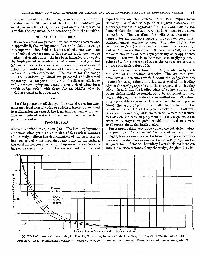
The collect of free-stream Mach number on the B curve ispresented in figure 4 (c) for free-stream Mach numbers of1.2, 1.3, 1.4, 1.5, and 2.0. For the wedge semiapex anglepresented in the figure (tan u= O.04), the value of -kfl= 1.2 isclose to the shock-wave-attadunent Mach number. Theshock-wnve-att achment Mach number is a function of thewedgo semiapax angle and is defined as that Mach numberbelow which the shock wave is detached from the wedge.An increase in the free-stream Mach number MI remits inan increased surface extent of perceptible impingement andalso in an increased value of B at any given distance S (except
Tqngent of
Ill
samiopexongle, tan u
.-
?
\
b)
O&me obq $fOce of v&e (fmrn Ie3ing edge), l!$ ft
(b) Effect of wedge semiapex angle. Droplet diatioter, 20miorcm;free-stream Mach number, 1.3; pressure altitude, 16,000 feet.
Figure 4.-Continued. Local impingement efflckncy on wodgo asfunction of distance along surface. Free-streamstatio tempomture,440” R.
at S=0, where L?=130=sin u and at S~m, whore HO).This increase in the surface extent of perceptible impinge-ment is shown in figure 4 (c), in which, for free-stream M(LCIInumbers of 1.2, 1.3, 1.4, 1.5, and 2.0, the surface extentsof perceptible impingement on the wedge (where B= 0.01130)are 5.35, 6.05, 6.65, 7.20, and 9.4 feet, respectively.
The effect of the droplet size on p is presented in figure 4 (d)for droplet diameters of 10, 20, 30, 40, 50, and 100microns. The surface extent of impingement and the valuesof B at any given distance S are considerably increased as thedroplet size is increased. For example, for the semiapoxangle prAented in the figure (tan u= O.06), at S=3 feet thevalues of 19are 0.0000, 0.0033, 0.0106, 0.0182, 0.0244, and0.0417 for values of droplet diameter of 10, 20, 30, 40, 60,and 100 microns, respectively. The surface extent of per-ceptible impingement has values of 1.5, 5.7, 11.2, 18.1, and
JMPINGEhfENT OF WATER DROPLEWS ON WEDGES AND DOUBLE-WEDGE AIRFOILS AT SIJTERSONIC SPEEDS 93
.040
.036 -
,032 \
028‘
Q
~-.024:“zczE,020—z:.~.oj6
33
012
.008
oo4-
(C)
0 2 ‘3 4D;tance abn~ surfox ~f wedge (%xn leodi~ edge), S~Oft
II 12 13 14
.02
.01
0
,06
.05
.03-\\\ \ \ I
)
, lx I I 1
10 2Distanmt along su~4me of w$ge (fro;!”mding ~ge), S, 2:
24 26 28 30 32
(o) Effeot of frea-etream Maoh number. Droplet diameter, 20 miorcms; tangent of semiapex angle, 0.04; prewsre altitude, 15,000 feet.(d) Effeot of droplet size. Free-stream Maoh numkwr, 1.3; tangent of mrniapex angle, 0.06; pmmum altitude, 15,000 feet.
FIGUEE4.—Conoluded. Local impingementefficiency on wedge as function of distancealong surface. Free-sham rstatiotemperature,440° R.#
— ——
94 RDPORT 115*NATIONAL ADVISORY COMMMT’EE FOR AERONAUTICS
.10) I I I I I I I I I I I I I L I II I I
I I.08 I
,
/ I I I I I I/ /
r.06
/ ( , I I I
Free-stream. _,M*.
P.”.W-1
.02
0Tangent of sernioIMx ang~ fun u
Pressure oltitud~ ft ‘
I I I I I I 1 / I 1 r/ l!
I I I III Y P I I
,5 J34 1 1 1 /1 II I I I H /’I / I I
I I I/1 II / I I I 1 I/
4 L4 !!YI I I I I.x
~ .008= ,
!006 /“
/ //
sol /
4‘/
.w12 f’/
(c)//
.00, 2 4 6 8 10 20 4060Droplet dtime!er, d, microns
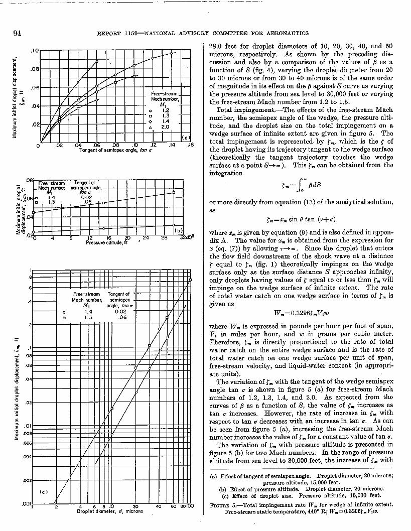
28.0 feet for droplet diameters of 10, 20, 30, 40, nnd 50microns, respectively. As shown by the preceding dis-cussion and also by a comparison of the values of 19as afunction of S (fig. 4), varying the droplet dkqneter from 20to 30 microns or from 30 to 40 microns is of the same orclorof magnitude in its effect on the /3against’S curve as vmyingthe pressure altitude from sea level to 30,000 feet or varyingthe free-stream Mach number from 1.2 to 1.$.
Total impingement,-The effects of the free-stream hfichnumber, the semiapex angle of the wedge, the pressure alti-tude, and the droplet size on the total impingement on wwedge surface of intinito extent are given in figure 5. TIIetotal impingement is represented. by ~., which is the t ofthe droplet having its trajectory tangent to the wedge surface(theoretically the tangent tmjcctm-y touches the wedgosurface at a point i%m ). This tn can be obtained from theintegration—
~m=J
- fIdSo
or more directlyfrom equation (13) of the analytical solution,as
rm=z. sin otan (P+u)
where w isgiven by equation (9) and is also defined in uppGn-dix A. The value for X* is obtained from the expression forz (eq. (7)) by allowing r+ co. ,Since the droplet that cn tcmthe flow field downstream of the shock wave at a distanco~ equal to ~~ (fig. 1) theoretically impinges on the weclgesurface only m the surface distance S’ approaches intinity,only droplets having values of f equal to or less than fm willimpinge on the wedge surface of intinite extent. Tho rateof total water catch on one wedge surface in terms of tm isgiven as
W~=O.3296~mVlw
where Wm is expressed in pounds per hour per foot of span,VI in miles per hour, and w in grams per cubic meter.Therefore, t= is directly proportional to the rate of totalwater catch on the entire wedge surface and is tho rato oftotal water catch on one wedge surface per unit of span,free-stream velocity, and liquid-water content (in appropri-ate units).
The variation of ~mwith the tangent of the wedge serninpcxangle tan u is shown in figure 5 (a) for free-stream Nfachnumbers of 1.2, 1.3, 1.4, and 2.o. & expected from thocurves of s as a function of S, the value of t- increases astan u increasw. ~owever, the rate of increme in r- Ivithrespect to tan u decreases with an increase in tan u. As canbe seen from figure 5 (a), increasing the free-stream Jllachnumber increases the value of ~mfor a constant value of tan u.
The variation of ~mwith pressure altitude is presented infigure 5 (b) for two l~ach numbem. In the range of pressuroaltitude horn sea level to 30,000 feet, the increase of ~= with
(a) Effect of tangentof semiapexangle. Droplet diameter,20 tiorom;pressurealtitude, 15,000feet.
(b) Effeat of pressurealtitude. Droplet diameter, 20 rniorons.(c) Effect bf droplet size. Preseum altitude, 15,000 feet.
FIGUEE5.—Total impingementrate ~. for wedge of iniinite estwt.Free-stri?amstatio temperature,440° R; ~.= 0.32fKY.T71w.

JMPRJGEMENT OF WATER DROPIJYI?S ON WEDGES AND DOUBIJ+WEDGE AIRFOIZS AT SUPERSONIC SPEEDS 95
an increase in pressure altitude is approximately linear.The variation of ~mwith the droplet diameter d in microns isshown in figure 5 (c). In the range of droplet diameter from10 to 100microns, in as a function of d results in a curvethat is very nearly a straight line when plotted on logarithmicpaper. This linearity permits an accurate interpolation of~m when calculations are made for a few droplet diamete~for a given value of free-stream Mach number, wedge semi-apex angle, and pressure altitude.
Droplet velpoities at impingement,-The variation of
V.,,JVI (ratio of droplet impingement velocity to free-stream velocity) with the surface distance along the wedgeis presented in figure 6 for three cssea. These three cases arerepresent ative of the results when tb e droplet diameter d isqO mic,ro~ and the pressure altitude is 15,000 or 30,000 feet.
The curves of V~,JVl as a function of S have characteristicssimilar to the curves presenting B as a function of S. AtS=0, obviously, all the curves have V.,JV, equal to unity;and, as S is increased, the value of the velocity ratio rapidlydecreases and asymptotically approaches V*/VI, the ratio ofthe air velocity downstream of the shock wave to the airvelocity upstrefirn of the shock wave. The solid curve infigure 6 illustrates a typical situation for which VJVI is verynearly unity (tan u= 0.02 and Ml=2.0). The two lowercurves (tan u=O.06 and 0.10 at T1l=l.3)are typical for caseswhere a stronger shock wave produced by a larger semiapexangle results in decreased values of V~,ti/Vl for large valuesof s.
SYMMETRICAL DO URI&WEDGE AIRFOIL
As shown in the ANALYSIS, the local impingementefficiency P at any point on the forward surfaces of a double-wedge airfoil (surfaces A B and AC in fig. 3) can be obtained
FIGURE 6.—Variation of ratio of impingement velocity of droplet tofree-stream velocity with distanm along surface of vwdge. F-@ream static. temperature, 440° R; droplet diameter, 20 microns.
directly from the results for the B against S’ curves for wedges.The local impingement efficiency P may be obtained fromfigure 4 or equation (17).
In general, the results for the impingement on a sym-metrical double-wedge airfoil are presented in this report interms of the total collection efficiency Emas a function of the .scale parameter +, in an attempt to conform with theexisting literature on the impingement characteristics ofairfoils. In the notation of the present report, the totalcollection e%ciency E. as stated in references 7 and 8is deli.ned as
(2,2)
Ic
ChordFree-stream
c, ft droplet,8 Pressure Reynolds
oltlhJde# number,ft Re,
0 Sea levelUE
803c1 I5,000
,+453
$ .6
0 30,000 239
‘GG%
.5nal=
~ .4~
$
.2
(o)
‘1 2 4 6S~ole pol&eter, *
m 40 E-9 80
(n) Effect of pressure rdtitude and chord length Droplet diameter, 20 miorons; free-stream hkch number, 1.4; airfoil thiokness ratio, 0.02.
FIGURE7.—Total collection efficiency of symmetrical double-wedge airfoils as function of male parameter. Free-stream static temperature,440° R; angle of attao~ OO.
308G15G-5~

—— -._—— .
96 “ REPORT 115&NAlZONAL ADVTSORY COMMI!LTEE FOR AEIRONA’UIHCS
w~ere T is the maximum. thickness of the symmetricaldouble-wedge airfoil, and l~J and ~,1are the absolute values ofthe initial displacements from the leading edge (in a directionnormal to free-stream direction) of the droplet trajectorieschat impinge at the shoulder of the upper and lower sur-faces, respectively, of the double-wedge airfoil. For thesymmetrical double-wedge airfoil at zero angle of attack, I{s]and Ifl] will be equal; at an angle of attack, the tangent ofwhich is equal to the thickness ratio, the value of lruI is equalto zero.
The scale pmamet er ~ is calculated for the double-wedgeairfoil at supersonic speeds as for other aufoils at subsonicspeeds. It is defined as
(23)
where c is the chord lengti of the double-wedge airfoil. Theresults present ed for impingement on double-wedge airfoilsuse essentially the same parameters as used for impinge-ment on wedges-droplet size, free-stream Mach number,double-wedge-airfoil thickness ratio, and pressure altitude.In addition, angle of attack and chord length are specitied.
Total collection efficiency at zero angle of attack.-Thevariation of the total collection efficiency 17~ with the scalepmameter * is presented in figure 7 for a symmetricaldouble-wedge airfoil at free-stream static temperature of440° R and zero angle of attack. The eflect of pressurealtitude on the variation of Em with # for a symmetricaldouble-wedge airfoil of 0.02 thiclmess ratio is given in figure7 (a) for droplet diameter of 20 microns and free-stream Machnumber of 1.4. The pressure altitudes presented in thefigure are sea level, 15,000, and 30,000 feet. The lines forconstant values of chord length from 1 to 20 feet are alsoincluded in the figure. For the double-wedge airfoil sub-jected to a constant-velocity supemonic flow field, the totalcollection efficiency Em increases slightly as the pressurealtitude is increased when the chord lmgth and the othervariables are held constant. Considering Em as a functionof scale parameter + where the droplet free-streamlteynoldsnumber ReI is held constant yields reanlts similar to thosefor airfoils having rounded leading edges at subsonic speeds.With Re, held constant, the value of Em decreases as x in-creases in the manner indicated in figure 7 (a). As pre-viously mentioned, the total collection efficiency and theimpingement rate at zero angle of attack for a symmetricaldouble-wedge airfoil are compared in appendix C withthose for an h~ACA 000644 airfoil.
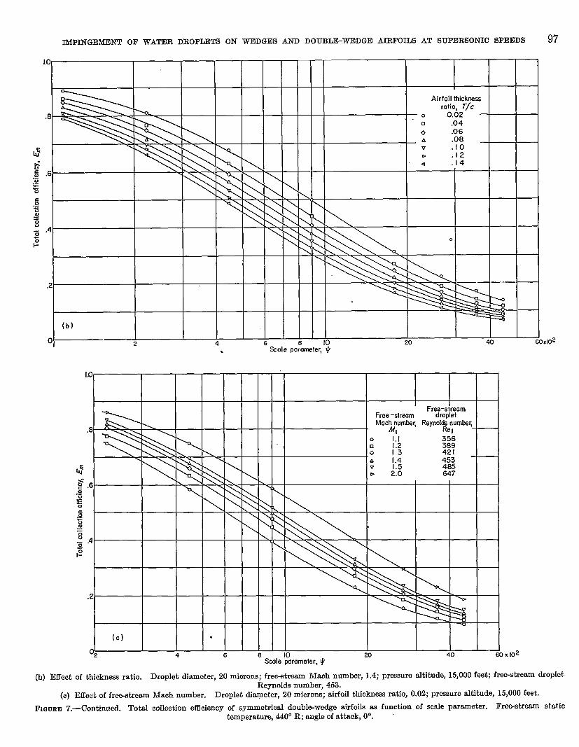
The effect of airfoil thickness ratio on the variation of E=with # is presented in figure 7 (b) for thickness ratios horn0.02 to 0.14, droplet diameter of 20 microns, free-streamMach number of 1.4, and pressure altitude of 15,000 feet.The droplet free-stream Reynolds number is maintainedat a value of 453 for all the curves. The effect of increasingthe airfoil thickness ratio is to decrease the total collectionetliciency. Thg rate of decrease in Em with an increase inairfoil thickness ratio becomes somewhat smaller as the”thickness ratio increase9.’
The effect of free-stream Mach number on the variationof total collection efficiency En with scale parameter 4 is
shown in figure 7 (c) for free-stream Mach numbers of 1.1,1.2, 1.3, 1.4, 1.5, and 2.0, droplet diameter of 20 microns,airfoil thickness ratio of 0.02, and pressure altitude of 16,000feet. The results show that the totrd collection efficiencyincreases as the free-stream Mach number increases. How-
ever, the increase in the totid collection eficiency from thofree-stream Mach number of 1.1 to 1.2 is considerablygreater than the increase in efficiency from a Mach number of1.2 to 1.3 and from 1.3 to 1.4, and so forth. calculationsfor thickness ratios of 0.04 and 0.06 indicate jhe same trend.For the 0.02 thickness ratio, the lomeat Mach number pre-sented in figure 7 (c) (M= 1.1) is quite close to the lirnitiugMach number for shock-wave attachment. Therefore, t,hcrate of decrease of total collection e5ciency with decrenaesin free-stream Mach number increasea os the Mach numberapproached the shock-wave-attachment Mach number as nlimit.
The effects of droplet size and chord length on the varin-tion of Emwith + are shown in figures 7 (d) and (e). Figure7 (d) presents curves of Emagainst # for a symmetrical double-wedge airfoil of 0.02 thickness ratio at a free-stream Machnumber of 1.4and a pressure altitude of 16,000 feet. Thocurves are for constant values of droplet diameter (d=10, 20, 30, 40, and 50 microns) as well as for constant valuesof chord length (c= 1, 2, 4, 8, and 20 ft). Increasing thodroplet size greatly increases the total collection efficiency.For ezmmple, at c=8 feet, the values of Em are 0.096, 0.310,0.495, 0.625, and 0.711 at droplet diameters of 10, 20, 30,40, and 50 microns, respectively. The rate of increase inthe total collection efficiency as the droplet diameter in-creases is lc%s for the larger droplet sizes. This effect cnnalso be observed in figure 7 (e), in which curves of .& ns ofunction of + are presented for a symmetrical double-wed~eairfoil of 0.06 thickness ratio for droplet diameters of 2, 10,20, 30,40, 50, and 100 microns, free-stream Mach number of1.3, and pressure altitude of 15,000 feet.
A comparison of figures 7 (b) and (c) (same droplet sizeand pressure altitude) shows that the effect on the totalcollection efficiency En of an increake in the free-streamMach number from 1.1 to 2.0 is, in general, of the samo orderof magnitude as a decrease from 0.14 to 0.02 thickness ratio.For example, for + of 1790 (c=S ft) in figure 7 (b), the vrdues”of Em decreased from 0.310 to 0.165 for an increase from n0.02 to a 0.14 thickness ratio, respectively, a decrense of0.145 in the value of Em. For + of 1790 (c=8 ft) in figure7 (c), the values of E~ increased from 0.230 to 0.400 for nnincrease in the free-stream Mach number from 1.1 to 2.0,respectively, an increase of 0.170 in the value of Em.
Another comparison of figures 7 (c) and (d) (same airfoilthickness ratio and pressure altitude) shows that the effecton the total collection efficiency Em of an incrense in tlwdroplet diameter from 10 to 50 microns is much greater thanan increase in the free-stream Mach number from 1.1 to 2.0.For axample, for c=8 feet in figure 7 (d), the value of Emincreased horn 0.095 to 0.710 for an incrense in the dropletdiameter from 10 to 50 microns, an increase of 0.616 in thevalue of Ea. As stated previously, for c=8 feet (#=1790)in figure 7 (c), the increase in the value of Emis 0.170 for ncorresponding increase in the value of the free-streamMach number from 1.1 to 2.0. For a constant value of
lMPINGEMONT OF WATER DROPLETS ON WEDGES AND DOUBLJ3-WEDGD AIRFOJLS AT SUPERSONIC SPEEDS 97
1.0
Airfoil thickrwsratio, T/c
.8❑ .04
0 “.06
\G b .12
6z .6.=Gzc \,-;al=8
.45z1-
a
.2
(b)
0, 2 4 6 10Scale pa%neter, +
20 4$J 60XI02
.
10
Free -stream droplet
\.8
\\ A
$
I.4 453
~ .6 \
.:
~
#
w=0
0 .4~
#
.2
(c) .
~2 4 6 8 10 20 40 mSale parameter, I+
}XKN
(b)IXfcctof thicknw ratio. Droplet diameter, 20 miorons; free-stream Maoh number, 1.4; prewue altitude, 15,000 feet; free-stream dropletReynolds number, 453.
(o) Effeot of free-stremn Maoh number. Droplet di~eter, 20 microns; airfoil tbiokness ratio, 0.02; prezsure altitude, 15,000 feet.
FIGURE7.—Ckmtinued. Total collection et3ciency of symmetrical doubl~wedge airfoils as funotion of scale Parameter. Fr-straam statiotemperat~ 440° R: angle of attack, O“.

— .— — .- .—.——. ——..—. —. —
98 RDPORT 115*NATIONAL ADVISORY COMMHT’EE FOR AERONAUTICS
.2.
Scale pammeter, *
wFree-streamdraplet
RewI&ls number.
~“ “’micnms
tlttl
\ :’\’& I \l 1 I I I I I I fA 30
Xd’Scale pammeter, I+
Re I~ 42.I21042163 I84210522104
(d) Effeat of droplet size and chord length. Free-etream Maoh number, 1.4; airfoil thickness ratio, 0.02; preeaure altitude, 15,000 feet.(e) Effect of droplet size. Free-etream Mach number, 1.3; airfoil thickness ratio, 0.06; pressure altitude, 15,000 feet.
FIGURE7.—Concluded. Total collection @&ency of eymmetrlcal double-wed~ airfoila ae ,funotion of scale parameter. Free-stream statiotemperature,440° R; angleof attaalqOO.
IMPINGEMENT OF WATFIR DROPLJWS ON WEDGES AND DOUB~-WEDGD MRFOm AT SUPIMWONICSPEEDS 99
chord length, varying the pressure altitude has a relativelysmall effect on the total collection efficiency (fig. 7 (a)).
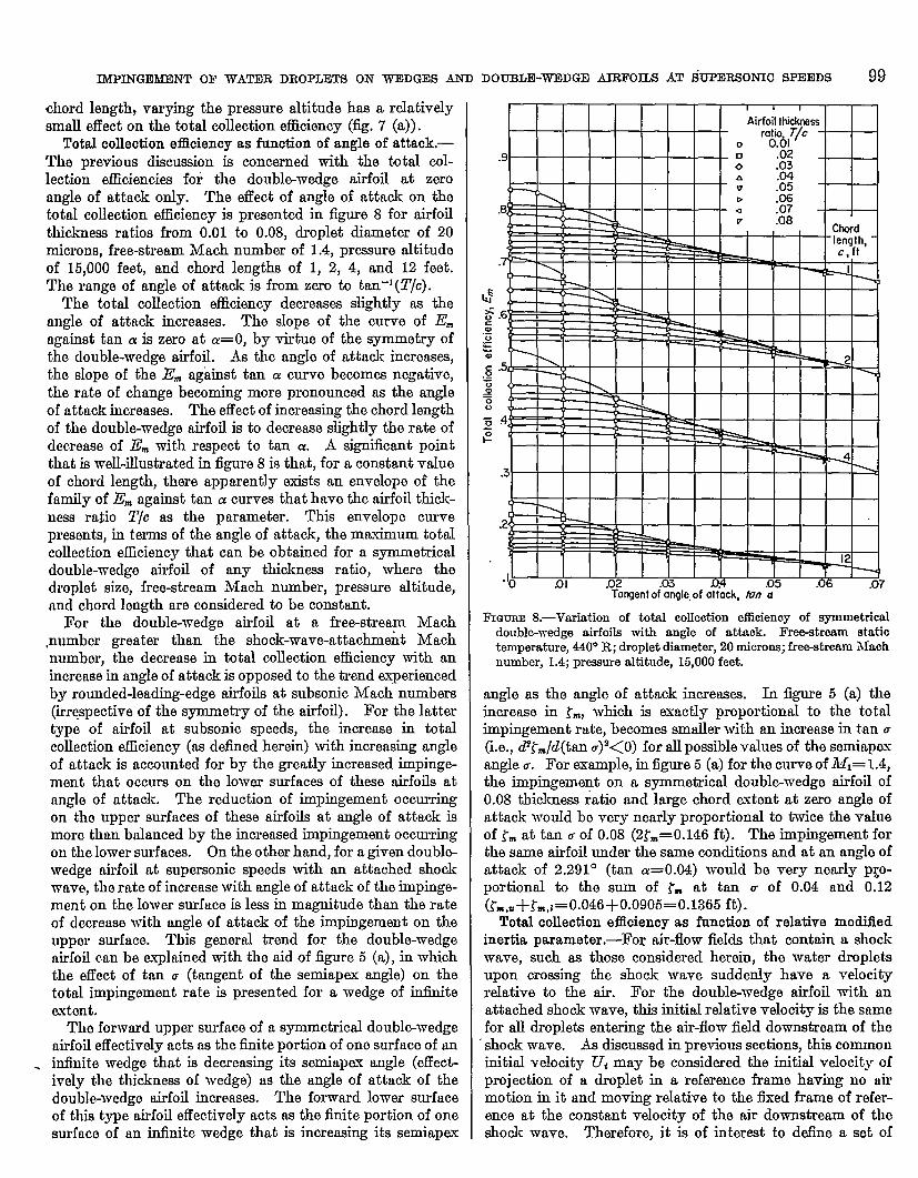
Total aolleotion effloiency as function of angle of attack.—The previous discussion is concerned with the total col-lection efficiencies for the doublewedge airfoil at zeroangle of attack only. The effect of angle of attack on thetotal collection efficiency is presented in figure 8 for airfoilthickness ratios from 0.01 to 0.08, droplet diameter of 20microns, free-stream Mach number of 1.4, pressure altitudeof 15,000 feet, and chord lengths of 1, 2, 4, and 12 feet.The range of angle of attack is from zero to tan-’ (T/c).
The total collection efficiency decreases slightly as theangle of attack increases The slope of the curve of Emagainst tan u is zero at a=O, by virtue of the symmetry ofthe double-wedge airfoil. As the angle of attack increases,the slope of the E. against tan a curve becomes negative,the rate of change becoming more pronounced as the angleof attack increases. The effeet of increasing the chord lengthof the double-wedge airfoil is to decrease slightly the rate ofdecrease of Em with respect to tan cr. A significant pointthat is well-illustrated in iigure 8 is that, for a constant value
of chord length, there apparently exists an envelope of thefamily of E. against tan a curves that have the airfoil thick-ness ratio T/c as the parameter. This envelope curvepresents, in terms of the angle of attack, the maximum totalcollection efficiency that can be obtained for a symmetricaldouble-wedge airfoil of any thickness ratio, where thedroplet size, free-stream Mach number, pressure altitude,and chord length are considered to be constant.
For the double-wedge airfoil at a free-stream lMach,number greater than the shock-wave-attachment Machnumber, the decrease in total collection efficiency with an
.
increasein angle of attack is opposed to the trend &periencedby rounded-leading-edge airfoils at subsonic Mach numbers(irrespective of the symmetry of the airfoil). For the lattertype of airfoil at subsonic speeds, the increase in totalcollection efficiency (as defined herein) with increasing angleof attack is accounted for by the greatly increased impinge-ment that occurs on the lower surfaces of these airfoils atangle of attack. The reduction of impingement occurringon the upper surfaces of these airfoils at angle of attack ismore than balanced by the increased impingement occurringon the lower surfaces. On the other hand, for a given doublewedge airfoil at supersonic speeds with an attached shockwave, the rate of increase with angle of attack of the impinge-ment on the lower surface is less in magnitude than the rateof decrease with angle of attack of the impingement on theupper surface. This general trend for the double-wedgeairfoil can be explained with the aid of figure 5 (a), in whichthe effect of tan u (tangent of the semiapex angle) on thetotal impingement rate is presented for a wedge of infiniteintent.
The forward upper surface of a symmetrical double-wedgeairfoil effectively acts as the finite portion of one surface of aninfinite wedge that is decreasing its semiapa angle (effectiively the thickness of wedge) as the angle of attack of thedouble-wedge airfoil increases. The forward lower surfaceof this type airfoil effectively acts as the finite portion of onesurface of an infinite wedge that is increasing its semiapex
I I 1
Airfoil Mkknessrat” T/c
o 0%1
.9 •1 .020 .03A
, v :%Da :%.8P .08
k
I 1
.2-K
05 .06 .07Tarqent of ongte.of attack, tin ~
FIQUREJ S.—Variation of total collection efficiency of symmetricaldouble-wedge airfoils with angle of attaak. Free-stream statictemperature, 440° R; droplet diameter, 20 miorons; free-stream Maohnumber, 1.4; pressure altitude, 15,000 feet.
angle as the angle of attack increases. In figure 5 (a) theincrease in ~m, which is exactly prcportiomd to the totalimpingement rate, becomes smaller with an increase in tan u(i.e., @~~/d(trm U)2<O) for all possible values of the semiapmangle u. For example, in iignre 5 (a) for the curve of JMI= 1.4,the impingement on a symmetrical double-wedge airfoil of0.08 thickness ratio and large chord ~xtent at zero angle ofattack would be very nearly proportional to twice the valueof ~~ at tan u of 0.08 (2~== 0.146 ft). The impingement forthe same airfoil under the same conditions and at an angle ofattack of 2.291° (tan a= O.04) would be very nearly pro-portional to the sum of t. at tan u of 0.04 and 0.12
&-,a+~~,z=0.046 +0.0906=0.1365 ft).Total collection efficiency as function of relative modiiled
inertia parameter,-For air-flow fields that contain a shockwave, such as those considered herein, the water dropletsupon orossing the shock wave suddenly have a velocityrelative to the air. For the double-wedge airfoil with anattached shock wave, this initial relative veloci@ is the samefor all droplets entering the air-flow field downstream of theshock wave. As discussed in previous sections, this commoninitial velocity Ui may be considered the initial velocity ofprojection of a drcplet in a reference frame having no airmotion in it and moving relative to the fixed frame of refer-ence at the constant velocity of the air downstream of theshock wave. Therefore, it is of interd to define a set of

— ...——— _——.—.. —
100 REPORT 115*NATIONAL ADVISORY CO~ FOR A33RONAUTICS.
inertia parameters, F and FO, breed on the motion Of thedroplet in this moving reference frame. The relativeinertia parameter based on the relative velocity u, is definedas
~=~ LJQ Sf_%. *v* 9 plc c
where K is the inertia parameter in the tied frame of refer-ence, detied as
(24)
and Z. ~ is that value of the maximum distance of travelobtained when Stokes’ law is assumed for the drag force onthe droplet.
The relative modiikd inertia parameter, also based on therelative velocity Uf, is detied as
FO=~ F=?
where Z. is defined in equation (9), and experimental valuesme used for the drag force on the droplet.
For the problem of water-droplet impingement on airfoilslmving rounded leading edges at subsonic speeds, it is im-possible to define a similar relative modified inertia param-eter. &o, for any airfoil at supersonic speeds, it is impos-sible tQ define a relative modified inertia parameta, unlessthe shock wave from the leading edge is of constant strength
in the vicinity of the airfoil, as in the case qf the doublo-wedge airfoils with attached shock waves. If the strmgthof the shock wave is not ionstant, as for the case of a bowshock wave preceding a blunt obstacle, then the value of .Fo
is not constant for all the trajectories of a given droplet size.Thus, the problem of impingement on wedges and doublo-wedge airfoils at supersonic speeds with attached shockwaves is unique in that a relative motied inertia paramotorcan be defined and used in correlating the total collectionefficiencies.
The correlation of the total collection efficiency with therelative modilied inertia parameter .3’0is shown in figure 9 (fi)for droplet diametem varying from 2 to 100 microns nndfor prcssmre altitudes of sea level, 15,000, and 30,000 feet.For the symmetrical double-wedge airfoil of 0.06 thicknessratio at MI= 1.3 and zero angle of attack, the droplet free-stream Reynolds number Rel varies from 42.1 to 2104. Thevalues of Em for a given thickness ratio, Mach number, andangle of attack generally form the basis for a single curvewith a small amount of scatter existing in the highm rangeof value of FO. In the lower range of Fo, for all values of Relthe plotted points have negligible scatter. The small scatterobserved is possibly due to the existence of a very slighttrend of the curves of Em against F. with Rel for the highervalues of Fo.
.
The effect of increasing the thickness ratioispresented in
figure 9 (b) for symmetrical double-wedge airfoils of 0.02,0.06, and 0.12 thickness ratio. Increasing the thicbessratio displaces the Em against F. curve toward larger values
) 43s0103 ZcQ 4md&2 .
(a) Correlation of pressure altitude and droplet size. Free—streamMach number, 1.3; airfoil thicknw ratio, 0.06.
Fmmm 9.—Total collection eflloiency of symmetrical doubl~wedge airfoils as function of relative modified inertia parameter. Free-stream statiotemperature, 440° R; angle of attaok, OO.

lMPINGEMDNT OF WATER DROPLETS ON WEDG13S AND DOTJDLE-WEDGE AIRFOILS AT SUPERSONIC SPEEDS 101
I.0
I I I I I I I I I I
I ““I Airfoil thick&s’/ I II HIIII
“et--b’ 0%’-1 I I I I I 1111 II I ratio. Tlc I I 11111111
‘-WFI-++
I , ,
.2
w- - 0--: ‘: z : 0 ~ ‘ ~d
//
(b) /“
%1 .02- .W- m .1 ‘- .2‘-.4..,24. 10 20 40M) Im 200 xIO-7.Relotive modified imrtio ~rameter, F.
,.
(b) Effect of thickness ratio. Droplet diameter, 20 microns; free-stream Maoh number, 1.4; premmre altitude, 15,000 feat.(o) Effect of free-etream Mach number. Droplet diameter, 20 microns; airfoil thickness ratio, 0.02; pressure altitude, 15,000 feat.
FIGURE9.—Conoluded. Total collection eilloiencyof symmetricaldouble-wedgeairfoils= function of relative moditied inertia parameter. Frce-stream static temperature, 440° R; angle of attao~ OO.

—. — .-. .— -.. — —.
102 REPORT 115*NA!ITONAL ADVISORY COMMII’TEE FOR AERONAUTICS
of FO. Changing the thickness ratio of the doubhvedgeairfoil does not alter the shape of the curve itself.
The effect of the free-strewn Mach number on the variationof l?= with ~0 is presented in figure 9 (c) for the symmetricaldouble-wedge airfoil of 0.02 thickness ratio for droplet diam-et er of 20 microns, free-stream Mach numbers of 1.1, 1.2,1.5, and 2.0,’and pressure altitude of 15,000 feet. kreasingthe Mach number displaces the entire curve of Em against
I’otoward smaller values of .FO. As the value of Ml increama,the rate of displacement of the curve with increasing Mlbecomes smaller. The displacement of the curve obtainedby increasing the Mach number from 1.1 to 1.2 is more thanthat obtained by increasing it from 1.2 to 1.5 and from 1.5to 2.0.
The relative inertia parameter ~ and’the relative modifiedinertia parameter ~. of the moving frame ‘of reference cor-respond, respectively, to the inertia parameter K and amod&d inertia parameter m of the fied frame of reference.The modified inertia parameter is detined in reference 14 as
Eo=;Ks
(25)
where A is the maximum distanm of travel of a drcpletprojected into still air with the free-stream velocity V1.The term A, is the value of the mtium distance of travel kwhen Stokes’ law is assumed for the drag force on the droplet.The total collection efficiency of a symmetrical doublewedgeairfoil is presented in appendix D as a function of the modiiiedinertia parameter &.
SUMMARY OF RESULTS
This report presents an analysis of the problem of im-
pingement of water dropletson a wedge and a double-wedge
airfoilat supersonic speeds with attached shock waves.
~en a suitable empirical relationis used for the drag co-
efficientof a sphere, the analysis allows a closed-form inte-
gration of the equations of motion for the water droplets.
The integration results in analytical expressions for the
equation of the trajectories,the droplet velocityat any point
on the trajectories,the local impingement efficiencies,and
the totalrate of impingement. The resultsof the calcula-
tions of rate, extent, and distribution of impingement of
water droplets on wedges and symmetrical double-wedge
airfoilsare summarized brieflyas follows (the Mach number
referredto isthe free-stream llaeh number, which isgreater
than the attachment ~lach number for the wedge or the
double-w-edge airfoil):
1. At a given value of Mach number, droplet size, andpressure altitude, the local impingement eflicienoy as afunction of the dimensional surface distance is the same forboth the wedge and the symmetrical double-wedge airfoilat zero angle of attac$, provided the tangent of the semiapexangle of the wedge is equal to the thickness ratio of the sym-metrical double-wedge airfoil.
2. I?or any Mach number, pressure altitude, and droplotdiameter, the value of @ois equal to the sine of the semiapexangle for wedge or symmetrical double-wedge airfoil. ~0is the value (maximum) of local impingement efficienqas distance from leding edge to point of impingementapproached zero.]
3. The effect of the free-shw.un static temperature on tlmlocal impingement efficien~ and total collection efficiencyis negligible for temperatures from 420° to 460° R.
4. At ccnstant values of Mach number, droplet size, rmdsemiapm angle of the wedge or corresponding thicknessratio of the symmetrical double-wedge airfoil, an increase inthe pressure altitude increases slightly the local impingementefficiencies and total collection rates on wedges and sym-metrical doublewedge airfoils, but has a negligible effecton the surface extent of perceptible impingement.
5. At constant values of Mach number, droplet size, andpressure altitude, increasing the thickness ratio of the sym-metrical double-wedge airfoil or corresponding smniapcmangle of the wedge increases the local impingement efficiency,haa a negligible effect on the surface extent of perceptibleimpingement, and decreases the total collection efficiencyof the symmetrical double-wedge airfoil.
6. At constxmt values of droplet size, pressure altitude,and semiapex angle of the wedge or thickness ratio of tlmsymmetrical doubbvedge airfoil, an increase in Machnumber increases both the surface extent of impingementand the value of the local impingement e5ciency.
7. At constant valuea of pressure altitude, semiapoxangle of the wedge or thiclmeas ratio of the symmetricaldouble-wedge airfoil, and Mach number, an incrmso inthe droplet size increasea considerably the surface extent ofperceptible impingement, the local impingement officionqy,and the total impingement rate.
8. The variation of total collection efficiency of the sym-metrical double-wedge airfoil at zero angle of attack as ofunction of the scale parameter for constant values of thedroplet free-stream Reynolds number is similar in form tothat for subsonic airfoils.
9. The total collection efficiency of the symmetricaldouble-wedge airfoil decreasea slightly m the angle of attackincrenses.
10. For a symmetrical double-wedge airfoil of a giventhiclmess ratio and Mach number, the values of totnl col-lection efficiency for a wide range of values of droplet free-~lmeam Reynolds number comprise a single curve whenplotted against the relative modified inertia parameter. Thee%’ect of increasing the thickness ratio or decreasing tlmMach number is to displace the entire curve in the directionof larger values of relative modiiied inertia parameter.
LEWIS FLIGHT PROPULSIONLABORATORYNATIONAL ADVISORY COMMITTEDFOR ADRONAUTHYS
CLEVELAND,Oreo, AM %1, 1968

IMPINGEMENT OF WATER DROPIJJTS ON WEDGES AND DOUBLE-WEDGE AIRFOILS AT SUPERSONIC SPEEDS 103
APPENDIX A
SYMBOLS
The followingsymbols are used in thisreport:
a
c.
c
DdEm
F
I“
Mmml n21n3
PRRer
Re,
s
Ttt,u
vwWpw
Xm,,
;
#o
droplet radius, ftdrag coefficient,dimensionless
airfoilchord length,ft
drag force on sphericalwater droplet,lb
droplet diameter, microns
total collectionefficiency(defined by eq. (22)),
dimensionless
2 p.(zzuiz= , henrelative inertia parameter, ——=-~
9 plc c -sionless
relative mod.ilied inertia parameter, ~ F=?
acceleration due to gravity, 32.2 ft(sec?2 P@a2V1
inertiaparameter, – —=$ dimensionlws9 /.llc
modified inertia parameter, ~K=$ dimensionlesss
Mach numberempirical constant (used in eq. (5)), 2/3constants of flow field (defined by eqs. (18a), (18b),
and (18c), respectively)static pressure, lb/sq ftgas constant, 53.3 ftAb/(lb) (“F)droplet Reynolds number relative to air behind
shock wave, 2ap2V/pz, dimensionlessfree-stream droplet Reynolds number, 2ap,VJPJ,
dimensionlessdistance to point of,impingement measured from
leading edge for water droplet that enters flow
fieldbehind shock wave at distance ~ above
leading edge (eq.(15)and fig.1),ftmaximum thicluwss of airfoil, fttime, secfree-tream static temperature, ‘Rmagnitude of droplet velocity relative to air
velocity downstream of shock wave, l~~—~zl, fpsvelocity, fps or mphrat e of water catch, lb/(hr) (f t span)local rate of water catch, lb/(hr) (sq ft surface)liquid-water content of air, g/cum
J
1U d.t,displacement of droplet in moving frame
oof reference (relative to air stream); where t= Othe instant water droplet intercepts shock wave
maximum value of displacement z as 7+ co as limit
(maximum distance of travel of droplet projectedinto still air with relative velocity Uf),”f t
value of maximum distance of travel z= obtti”edby assuming Stokes? law for drag force on
droplet, ftangle of attack of airfoil, deglocal impingement efficiency, dl/dS, dimensionlessmaximum value of B as S’4; PO=sin u, dimensions
I&s
ratio of specitlc heats (1.4 for air)empirical constant (used in eq. (5)), 0.158, dimen-
sionlessinitial displacement of droplet trajectories from
leading edge in direction normal to free-streamdirection (eq. (13))
maximum value of initial droplet displacement ~obtained when trajectory is tangent to wedgesurface (theoretically as S+ m)
absolute values of initial displacement from leadingedge (ii direction normal to free-stream direc-tion) of droplet trajectories that impinge atshoulder of upper and lower surfaces, respec-tively, of double-wedge airfoil
distance along shock wave measured from wedgeapex to point where droplet trajectory interceptsshock wave
shock-wave angle
angle between free#iream velocity vector ~1 and
droplet velocity vector Tdmaximum distance of travel of droplet projected
into still air with free-stream velocity VI) ftvalue of distance of travel 1 obtained by assuming
Stokes’ law for drag force on water droplet, ftdynamic viscosity based on static temperature,
(lb) (see)/sq ft
angle between free&ream velocity vector ~1 and
initial relative velocity vector ~t (defined by eq.(13a))
components of droplet displacement referred towedge surface (delined by eq. (12)), ft
mass density of air, slugs/cu ftwaterdroplet mass density, 1.9398 slugs/cu ftsemiapax angle
angle between droplet Vdocity vector ~d and
velocity vector 72
dimensionless time variable, (3~/pt4z2)t
phase angle, tan-l (Rer,~-113e-1)2),
scale parameter, (9c/a) (pJpm)ratio of air velocity downstream
free-stream velocity VJV,ratio of initial droplet relative
stream velocity ti~VlSubscliptw ,
d droplet‘i initial (at shock wave)im impingement1 lowerm maximumu upper1 free stream2 downstream of shock wave (in
reference)
Barred symbols denote vectorial quantities.
OS PS; (eq. (9))
of shock wave to
velocity to free-
fkxed frame of

— — — ——. .—.
104 REPORT 115*NATIONAII ADVISORY COMMI’lTEE FOR AERONAUTICS
APPENDIX B
CLOSED-FORM INTEGRATION OF EQUATION OF MOTION (RELATIVETO AJR FLOW DOWNSTREAM OF SHOCK WAVK)
The various steps necessary to the closed-form integrationof equation (6), which is the d.iihrential equation of motionof the water droplet in the moving reference frame, are givenherein. The differential equation of motion (6) can be re-written as
dU “~ (1+eArUrna”)X=–X a’
@l)
where, for convenience,
Re,=A,Ua @2)
(B3)
@34)
Algebraic simpliikation and rewriting result in the form
A, dU‘t=–u(l +A.u”) (135)
where
(B6)
andA,= eAra” (B7)
Equation @5) is not readily integrable in its present form.By letting
p=u” @8)
and
pt.– p –u”pi m
(B9)
equation (B5) becomes
dt= –$ y+h ‘p’ ‘p’m 1+A-#tp’ @lo)
This form of the equation is readily integrated, and uponresubstituting the relations @) and @9), there is obtainedthe following expression for the velocity of the droplet as afunction of the time t:
where .B1is the constant of integration.
Since U=%, equa’tion @n) can be rewritten in iutegral
form as
where Bz is tie second integration constant. IZquation@312) requires simplification before a closed-form integrationcm he performed. Consider the following substitutions:
(3313)
A5=$ Ut~A,)-l/”=# (A,) -llrn (3314)
A,=(nA,)-’ exp [–B,m/A3] (B16)
By using the substitutions given by @13), @14), and (B16),it is possible to write equation (B12) as
SSdx= A5(A,ev– l)-l/mdy+-& (B16)
Before further steps can be taken in the closed-form iutegrrt-tion- of the equation of motion of the droplet, the value ofthe empirical constant m must be detemnined. It is notedthat in approximating the curve of the drag coefficient as afunction of the local Reynolds number by a relation of theform given by
CD=% (1+ eRe> (5)
itispossible to consider that the value of m is 213 and thevalue of e is 0.158. That the approximation of the e.spmi-mental curve by the empirical relation is very good in tierange of Reynolds numbers from about 0.5 to 600 can beseen by refeming to figure 2, which presents Q graph of theempirical relation along with the drag-coefficient data ofreferences 4 and 12.
The use of m=2/3 in equation (B16) along with the sub-stitution
ew= q (3317)
and the use of formulas of integration given on pages 16 and17 of reference 15 allow equation (1316) to be integrated Mshown in the following steps:
SS(ix=
q(A~~~ql)’n+B2
JA=-J ‘“q J(A;%P+B2q(Asq—l)lfl+Ae
z—Bz__2Ab &
–tan-’ J- (B18)
H the original time or independent variable tisreintroducedinto equation (1318) and the substitutions are made for A5md &, the equation has the form
:A4)3fl(B2–z)= (A, U,’@)’/’3A3
44%?)I-A4U’2’: ‘
(B19)
\
●
IMPINGEMENT OF WATER DROPIJWS ON WEDGES AND DOUBLJ+WDDGE AIRFOILS AT SUPERSONIC SPDEDS 105
Substituting for A, and & (except in the exponent of e) inoquution (B19) results in
(1320)
J3quation (B20) is the integrated equation with undeter-mined inte.gmtion constants for the motion of the waterdroplets relative to the air velocity behind the shock wave.The integration constants are determined from the boundaryconditions, which are
u= u,1
at t=OZ=’o
The substitution of the bounda~ conditions, and thus thedetermination of the integration constants .BI and 132,results in the fmrd form of the integrated equation of motionfor the water droplets relative to the air velocity down-
stream of the shock wave as follows (in the frame of refer-ence moving with the constant velocity T~q):
1
J(Re,,, -2/3,-1+ I)er_ ~ 1–t,m-’@er, ,-’/’e-’+l)er– 1 (7)
The final form of the ccmx+ponding equation for the relativevelocity of the water droplet as a function of the dimension-less time variable is obtained from equation (B1l) m
‘=R~ ‘(Re” “lSC-’+ l)e’– 1] ‘3/’ (8)
It can be seen from equations (7) and (8) that as t approachesinfinity the value of U approaches zero and that a limitexists for the value of x as t approaches infinity. Thislimiting value of z is
APPENDIX c
COMPARISON OF COLLECTION EFFICIENCY AND IMPINGEMENT RATE FOR SYMMETRICAL DOUBLE-WEDGE AIRFOILWITH THOSE FOR NACA 0006-64AIRFOIL
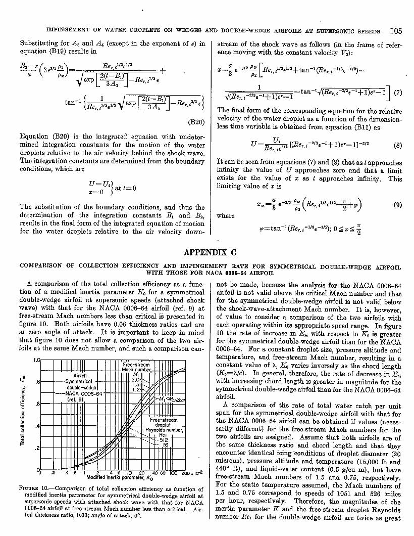
A comprtrison of the total collection efficiency as a func-tion of a moditied inertia parameter & for a symmetricaldouble-wedge airfoil at supersonic speeds (attached shockwave) with that for the hTACA 0006-64 airfoil (ref. 9) atfree-stream Mach numbers less than critical ii presented infigure 10. Both airfoils have 0.06 thiclmesa ratios and areat zero angle of attack. It is important to keep in mindthat figure 10 does not allow a comparison of the two air-foils at the same Mach number, and such a comparison can-
; “l=EE’5iiI#
iiF
,2
?1 2 .4s1 4060 Ico 2@Jx lo-2Modi%sd h&t; &met~ KO
FIGURE10.—Comparison of total oolfeotion efficiency x function ofmodified inertia parameter for symmetrical double-wedge airfoil atsupersonic spseds with attached shock ~Ve ~th t~t for NACA0006-(34afrfoil at free-streamMach number 10SSthan critical. Air-foil thloknws ratio, 0.06; angle of attack, OO.
not be made, because the analysis for the NACA 0006-64airfoil is not valid above the critical Mach number and thatfor the symmetrical double-wedge airfoil is not valid belowthe shock-wave-attachment Mach number. It is, however,of value to consider a comparison of the two airfoils witheach operating within its appropriate speed range. In figure10 the rate of increase in Em with respect to & is greaterfor the symmetrical double-wedge airfoil than for the ~ACA0006-. For a constant droplet size, pressure altitude andtemperature, and free-stream Mach number, resulting in aconstant value of h, & varies inversely as the chord length
(&=~/c). k general therefore, the rate of decrease in E=with increasing chord length is greater in magnitude for thesymmetrical double-wedge airfoil than for the hTACA 0006-64airfoil.
A comptin of the rate of total water catch per unitspan for the symmetrical double-wedge airfoil with that forthe NACA 0006-64 airfoil can be obtained if values (neces-sarily diflerent) for the free-stream Mach numbers for thetwo airfoils are assigned. Assume that both airfoils tie ofthe same thickncsa ratio and chord length and that theyencounter identical icing wnditions of droplet diameter (2omicrons), pressure altitude and temperature (15,000 ft and440° R), and liquid-water content (0.5 g/cu m), but havefree-stream Mach numbers of 1.5 and 0.75, respectively.For the static temperature asaumed, the Mach numbers of1.5 and 0.75 corr~pond to speeds of 1051 and 526 milesper hour, respectively. Therefore, the maetitudes of theinertia parameter K and the free-stream droplet Reynoldsnumber Rel for the double-wedge airfoil are twice as great

.
106 REPORT 115*NATIONAL ADVISORY COMMTI’TEE FOR AERONAUTICS
.= I 1.= I
.2
, ,
(a)4 - =
5 -cr
%iiii= ‘ .4 .6 I 10 20 406010021XI 4(XI Em Kmdo=Mo%ified in;rtia ~arameter, K.
(a) Correlation of p=ure altitude and droplet size. Free-stream Mach number, 1.3; airfoil tbicknesa ratio, 0.06.(b) Effeot of thiokn- ratio. - Droplet diameter, 20 miorons; free-stream Maoh number, 1.4; pre+sure altitude, 16,000 feet.(c) Effect of free-stream Mach number. Droplet diameter, 20 miorons; airfoil thioknem ratio, 0.02; prawre altitude, 15,000 feet.
FIGURE1l.—Total collection efficiency of symmetrical double-wedge airfoils as function o; modified inertia wrameter. Free-streamst~tiotemperature,440° R; angleof attaok, OO.

lMYINGEMIiNTOF ~ATEB DROPLETS ON WEDGES AND DOUBLZ-~DGEI _OILs AT SUPERSONIC SPDEDS 107
as for the NACA 0006-64 airfoil. Varying the chord lengthfrom 1 to 20 feet produces a change in the value of.& from0,386 to 0.0193 for the double-wedge airfoil ahd from 0.266to 0.0130 for the NACA 0006% airfoil. This variation in& for both airfoils results in values of lZmof the same orderof magnitude. For the given icing conditions, the followingtable lists for chord lengths of 4 and 20 feet the various p~r-tinent parameters and variables, including the rate of totalwater catch on the airfoil per unit span for both airfoils:
Sgmmdriaddonble-~edgeoIrfollatM-1.6 (ViH1051mph) I
l—l_TlTid7mi_tTFwl$NAOA CIW3+34Wfoll at M-o.7u (VI=~ mph)
.
I242
I0.271 0.246
2!I
aw243 I
O.w.0bi2 .246 .OH .Iz3 I 1: i?
The rate of total water catch on the airfoil per unit span iscalculated from
Wn=0.3296&TVlw
where T is in ftiet, w in grams per cubic meter, and VI inmiles per hour. For this particular emmple, the table showsthat for the 4-foot chord, the double-wedge airfoil has asomewhat larger value of E= than the NACA 0006-64 air-foil; and for the 20-foot chord, the opposite is the case.Comparison of the two airfoils for a given chord lengthshows that, as mpected, the effect of the total collectionefficiency on the rate of water catch is small when comparedwith the free-stream veloci@- ratio chosen (2:1). The mostsignificant comparison to be obtained from the table is that,for the double-wedge airfoil, increasing the chord length by afactor of 5 (from 4 to 20 ft) results in .an increase of only 28percent in the rate of water catch; whereas, for the IVACAairfoil, alike change in the chord length rcmdts in an increaseof 94 percent. This difference is the result of the fact that,unlike the local impingement on the rounded-leading-edgeairfoils at free-stream Mach numbers less than critical, thelocal impingement at a given point on the surface of adouble-wedge airfoil does not vary with the chord length ofthe airfoil, which is at a supemonic Mach number above theshock-wave-attachment Mach number..
APPENDIX D.
TOTAL COLLECTION EFFICIENCY OF SYMMETRICAL DOUELE-WEDGE AIRFOILS AS FUNCTION OF MODIFIED INERTIAPARAM3WER
The total collection efficiency ,Ea is presented in figure 11as D function of the modiiied inertia parameter -&j as sug-gested in reference 14. The relation for&is
where K is the inertia parameter,” defined as
,(25)
(24)K– : PW;:CVI
Since K is equal to h,/c (ref. 4), & may also be written as
~=+K=?1 c
The free-stream droplet Reynolds numbers used herein incalculating & range up to 2104. The empirical drag law(eq. (5)) tied in this report for the droplet motion in themoving reference frame is valid up to the Reynolds number ofapproximately 500. Therefore, for the values of & pre-sented in figure 11 (and also fig. 10), the values of X/X, wereobtained from table I of reference 4.
The curves of E= against .&in figure 11have exactly thesame form as the curves of E= against Fo, mcept that the useof K results in a displacement of the entire curve towardlarger abscissa values. The displacement of the Em against& curves obtained by varying the thiclmess ratio (@g. 11 (b))or the free-stream Mach number (@g. 11 (c)) is lws thanthe displacement of the En against FOcurves obtained by thesame procedures (figs. 9 (b) and (c)).
.

108 REPO13T 115&NATfONAL ADVISORY COMMITTJ3E FOR AERONAUTICS
REFERENCES
1. Cahghan, E&nund E., and Serafini, John S.: Analytical kwti~tion of Icing Limit for Diamond Airfoil in Transonic and Super-SOIliO FIOTV. NACA TN 2661, 1953. “
2. Glauert, Muriel: A hfethod of Constructing the Paths of Raindropsof Different Diametem Moving in the Neighborhcmd of (1) aCircular Cylinder, (2) an Aerofoil, Placed in a Uniform Streamof Air; and a Determination of the Rate of Deposit of the Dropson the Surface and the Percen@ge of Drops Caught. IL & M.No. 2026, British & R. C., 1940.
3. Kantrowitz, Arthur: Aerodynamic Heating and the Deflection ofDrops by an Obstacle in an Air Stream in Relation to ‘Aim-aftIcing. NACA TN 779, 1940.
4. Langmuir, Irving, and Blodget& Katherine B.: A MathematimlInvdigation of Water Droplet Trajectorim. Teoh. Rep. No-5418, & Materiel Command, AAF, Feb. 19, 1946. (ContmctNo. W–33-036-ae9151 with General Electric Co.)
5. Brun, Rinaldo J., and Mergler, Harry W.: Impingement of WaterDroplets on a Cylinder in an Incomprewible Flow Field andEvaluation of Rotating Multioylindw Method for Measurementof Droplet+ize Distribution, Volume-hkiian Droplet Size, andLiquid-Water Content in Cfouds. NACA TN 2904, 1953.
6. Bergrun, Norman R.: A Method for Numerkdly Calculating theArea and Distribution of Water Impingement on the IkadingEdge of an Airfoil in a Cloud. NACA TN 1397, 1947.
7. Guibert, A. G., Jansen, E., and llobb~, W. M.: Determination ofRate, A% and Distribution of Impingement of Waterdrops onVarious Airfofls from Trajeotoriea Obtained on the DifferentialAnalyzer. ATACA RM 9A05, 1949.
8.Brun, Rfnaldo J., Se@ni, John S., and Moshos, Georgo J.: Im-pingement of Water Droplets on an NACA 651-212 Alrfoll at anAngle of Attaok of 4°. NACA RM E62B12, .1052.
9. Lenherr, F. E., and Thomson, J. E.: Preliminary Report on thoComputation of Water Drop Trajectories about a 6-PoroontAirfoiL TDM-67, N&throp Aircraft, Ino., Aug. 14, 1962.
10. Brun, Rinaldo J., Serafini, John S., and Gallagher, Helen M,:Impingement of Cloud Droplets on Aerodynamic Bodios asAEected by Compressibility of Air Flow Around tho Body.NACA TN 2903, 1953.
11. Tribus, Myron, and Gulbert, Armand: Impingement of SphorlcrdWater Droplets on a Wedge at Supersonic Speeds in Air. Jour.Aero. Sci., VOL19, no. 6, June 1952, pp. 301-394.
12. Wlliams, Glenn Carber: Heat Transfer, MS Transfer and Frio~tion for Sphenss. Sc. D. Thesis, M. I. T., 1942.
13. The Staff of the Ames 1- by 3-Foot Supemonio Wind-TunnelSection: Notes and Tablea for Use in the Analysis of SuporeonioFlow. NACA TN 1426, 1947.
,14. Sherman, P., Klein, J. S., and Tribua, M.: Determination of DropTrajectories by Means of an Extension of Stokes’ Law. Eng.I&s. Inst., Air Res. and Dev. Command, USAF, Univ. Mioh.,Apr. 1952. (Contract AF 1S (600)-51, Proj. M992-D.)
15. Peirce, B. O.: A Short Table of Integr&. Third cd., Ginn andb., 1929. .
16. DiehI, ~alt.er Stuart: Engineering Aerodynamic. %cond cd.,The Ronald Prcm Co., 1936.
.
.