report documentation page 07-04-2009
TRANSCRIPT

REPORT DOCUMENTATION PAGE Form Approved OMB No. 0704-0188
The public reporting burden for this collection of information is estimated to average 1 hour per response, including the time for reviewing instructions, searching existing data sources, gathering and maintaining the data needed, and completing and reviewing the collection of information. Send comments regarding this burden estimate or any other aspect of this collection of information, including suggestions for reducing the burden, to Department of Defense, Washington Headquarters Services, Directorate for Information Operations and Reports (0704-0188), 1215 Jefferson Davis Highway, Suite 1204, Arlington, VA 22202-4302. Respondents should be aware that notwithstanding any other provision of law, no person shall be subject to any penalty for failing to comply with a collection of information if it does not display a currently valid OMB control number.
PLEASE DO NOT RETURN YOUR FORM TO THE ABOVE ADDRESS.
1. REPORT DATE IDD-MM- YYYY)
07-04-2009 2. REPORT TYPE
Final DATES COVERED (From - To)
06/16/2005 to 12/31/2008 4. TITLE AND SUBTITLE
Optimization, Alternative Materials and Improvements in Body Armor Shields
5a. CONTRACT NUMBER
N00014-05-1-0826
5b. GRANT NUMBER
5c. PROGRAM ELEMENT NUMBER
6. AUTHOR(S)
Batra, R. C, Zhang, G. M., Zheng, J. and Gopinath, G. 5d. PROJECT NUMBER
5e. TASK NUMBER
5f. WORK UNIT NUMBER
7. PERFORMING ORGANIZATION NAME(S) AND ADDRESS(ES)
Virginia Polytechnic Institute and State University Department of Engineering Science and Mechanics, M/C 0219 Blacksburg, VA 24061
8. PERFORMING ORGANIZATION REPORT NUMBER
9. SPONSORING/MONITORING AGENCY NAME(S) AND ADDRESS(ES)
Office of Naval Research One Liberty Center (Suite 1425) 875 North Randolph Street Arlington, VA 22203-1995
10. SPONSOR/MONITORS ACRONYM(S)
ONR 11. SPONSOR/MONITOR'S REPORT
NUMBER(S)
12. DISTRIBUTION/AVAILABILITY STATEMENT
Unlimited t>il»+^"' ^TTCV,,
13. SUPPLEMENTARY NOTES
14. ABSTRACT
In the first part of the work, we analyze, with the computer code LS-DYNA, three-dimensional (3D) transient deformations of a 10-layer woven Kevlar armor held in a square steel frame and impacted at normal incidence by a 9 mm FMJ (full metal jacket), 124 grain projectile. The composite armor is discretized into weft and warp yarns to simulate its woven structure. The yarn is modeled as a 3D continuum. We consider failure of the yarn, and friction between adjoining layers and between the armor and the frame bars. For the armor perfectly bonded to the rigid frame bars, the computed residual speed and the residual kinetic energy of the projectile are found to increase with a decrease in the frame size implying thereby that the armor fixed in a smaller frame will have lower V50 than that of the same armor clamped in a larger frame. (The V50 of an armor equals the speed of a standard projectile that upon normal impact has 50% probability of just perforating the armor). For the armor allowed to slide between the frame bars, we have studied the effect of the pressure applied to the bars of the two- and the four-bar frames on the speed and the kinetic energy of the
15. SUBJECT TERMS nnrt tVin fmir hnr frnmnn—tUr. nnr*nA r*-F<-U~ .-,-,,•,f4..^l ~.-.., ^,.». ],, ,.- P..,.~^-l t~ .^^.-.^r.^ -
soft body armor, effect of frame type and size, effect of resin matrix.
16. SECURITY CLASSIFICATION OF:
a. REPORT
U b. ABSTRACT
LA.
c. THIS PAGE
17. LIMITATION OF ABSTRACT
18. NUMBER OF PAGES
19a. NAME OF RESPONSIBLE PERSON
Rov^eSH C. ¥>r\TRfy 19b. TELEPHONE NUMBER /Include area code)
Standard Form 298 (Rev. 8/98) Prescribed by ANSI Std. Z39.18

ELSEVIER
Available online at www.sciencedirect.com
*•#* ScienceDirect Composites: Part B 39 (2008) 476-489
compos/res Part B: engineering
www.elsevier.com/locate/compositesb
Effect of frame size, frame type, and clamping pressure on the ballistic performance of soft body armor
G.M. Zhang a, R.C. Batra a*, J. Zheng b
• Department of Engineering Science and Mechanics, MIC 0219, Virginia Polytechnic Institute and State University, Blacksburg, VA 24061, United States b Program Executive Office - Soldier, US Army, 15395 John Marshall Highway, Haymarket, VA 20169, United States
Received 23 February 2007; accepted 12 April 2007 Available online 10 May 2007
In memory of Professor Kevin Granata who was killed on 16 April 2007 during the massacre in Norris Hall, Virginia Tech.
Abstract
We analyze, with the computer code LS-DYNA, three-dimensional (3D) transient deformations of a 10-layer woven Kevlar armor held in a square steel frame and impacted at normal incidence by a 9 mm FMJ (full metal jacket), 124 grain projectile. The composite armor is discretized into weft and warp yarns to simulate its woven structure. The yarn is modeled as a 3D continuum. We consider failure of the yarn, and friction between adjoining layers and between the armor and the frame bars. For the armor perfectly bonded to the rigid frame bars, the computed residual speed and the residual kinetic energy of the projectile are found to increase with a decrease in the frame size implying thereby that the armor fixed in a smaller frame will have lower V50 than that of the same armor clamped in a larger frame. (The V50 of an armor equals the speed of a standard projectile that upon normal impact has 50% probability of just per- forating the armor). For the armor allowed to slide between the frame bars, we have studied the effect of the pressure applied to the bars of the two- and the four-bar frames on the speed and the kinetic energy of the residual projectile. For both the two- and the four-bar frames, the speed of the residual projectile is found to increase with an increase in the applied pressure. Computed results also show that the armor fixed in the two-bar frame exhibits higher impact resistance than that held in the four-bar frame. The V50 is found to be ~270 m/s when the woven armor is held in a four-bar frame with a clamping pressure of 200 MPa. The V50 decreases with an increase in the pressure applied to either the two-bar or the four-bar frames. © 2007 Elsevier Ltd. All rights reserved.
Keywords: A. Yarn; B. Fracture; B. Impact behavior, C. Finite element analysis (FEA); Ballistic performance
1. Introduction
Composite materials have been widely used in many
high-performance structures such as protective clothing,
bullet-proof vests and helmets due to their high-specific
strength and stiffness. The ballistic performance of soft
body armor is characterized by V50, which is usually deter-
mined experimentally, and equals the velocity of the projec-
tile that upon normal impact on the armor has 50%
probability of penetrating it.
Corresponding author. Tel.: +1 540 231 6051; fax: E-mail address: [email protected] (R.C. Batra).
-1 540 231 4574.
1359-8368/$ - see front matter © 2007 Elsevier Ltd. All rights reserved. doi:10.1016/j.compositesb.2007.04.002
Parameters affecting the ballistic performance of com- posite armor include material properties of the yarn, woven structure of the armor, projectile geometry, projectile velocity and its material, boundary conditions imposed on the armor, friction between the yarns, and friction between the yam and the projectile. Duan et al. [1] used LS-DYNA to delineate effects of frictional forces on the ballistic performance of one-layer woven rectangular com- posite with all four edges either clamped or only two oppo- site edges clamped. However, they did not consider the failure of the projectile and the composite. A recent review paper [2] has discussed the effect of different material and geometric parameters on the ballistic performance of soft body armor.
20090416078

GM. Zhang et aL I Composites: Part B 39 (2008) 476-489 477
Generally in ballistic experiments the boundary of the armor system is held in a rectangular frame with pressure applied to the frame bars to hold the armor in place. Two different frames, namely, two-bar and four-bar, are employed. Also frame size can be varied by adjusting the distance between the opposite bars of the frame. Shockey et al. [3] experimentally ascertained the effect of boundary conditions on the ballistic performance of the armor and found that for both the 25 g blunt and the 26 g sharp frag- ment simulating projectile (FSP), the armor fixed on two opposite edges rather than on all four edges was more effec- tive in reducing the kinetic energy of the projectile. Since experiments are very expensive to perform, it will be more economical if one could accurately delineate computation- ally the effect of the frame size and the pressure applied to its bars on the V50. We note that small values of the applied pressure may not hold the armor well, and when impacted it will slide between the frame bars. However, very large values of this pressure may fracture the armor within the frame bars. Thus the ballistic performance of the armor is likely to depend upon the pressure applied to the frame bars and the frictional force between the yarn and the frame bars. Lee et al. [4] have studied experimentally the effect of the clamping pressure on the penetration resis- tance of a 5-ply composite laminate and found that the loss of the kinetic energy of the projectile decreased with an increase in the clamping pressure.
Hundreds of parallel high-strength and high-modulus fibers are grouped together to form a yarn and yarns are woven to form a single-ply fabric. It is still not possible to consider each fiber individually because of enormous computational resources required. A possibility is to model woven armor as an assembly of one-dimensional (ID) bar elements [5,6]. Tan and Ching [7] replaced the one-layer composite with a network of viscoelastic bars. For suitable values of material parameters, they found that computed results agreed very well with the ballistic test data. Baraus- kas and Abraitiene [8] simulated the armor with thin shell elements of thickness equal to that of the yarn. A more realistic discretization of the composite is obtained by using 3D solid elements that can account for orthotropic mate- rial properties, inter-yarn and inter-layer friction, material failure and undulations in the woven yarns. Gu [9] consid- ered the actual structure of plain-woven fabrics and devel- oped 3D finite element discretization of the woven composite into weft and warp yarns. The multi-layered woven composite was impacted by a steel projectile and the computed results were compared with the experimental data. However, the failure of the projectile was not considered.
There are three methods to determine the ballistic limit of a soft armor. An accurate but very expensive method is to carry out a large number of ballistic experiments. However, it is tedious to experimentally characterize the effect on V50 of each parameter, such as the projectile shape and material, armor material, armor thickness, and armor architecture. An alternative is to employ an
approximate model [10] of the armor system, analyze the problem analytically and establish scaling laws. The success in this case depends upon our understanding of the mechanisms involved in the penetration process and how well they can be incorporated in the analytical model. The third possibility is to use a numerical method such as the finite element method that finds an approximate solution of the pertinent initial-boundary-value problem but can incorporate realistic material behavior, complex geometries, friction effects, and material failure. The analysis can be easily modified when additional informa- tion on the material response and failure becomes available. After the mathematical model and the computa- tional algorithm have been validated one can perform parametric studies, determine the V50, and also delineate parameters to which it is most sensitive. Is this case V50
equals the minimum projectile velocity with which the tar- get when impacted at normal incidence is penetrated com- pletely. A few experiments are needed to validate this technique.
Sun and Potti [11] proposed the following relation
1 ^DP 7\-v\)
among the initial velocity V%, the residual velocity KR of the projectile of mass m, and the energy £DP required to com- pletely perforate a target. Here E&P is assumed to be con- stant, and the projectile not to fail during the penetration process. This relation does not account for the energy re- quired to deform the armor, and that dissipated due to fric- tion effects. Lim et al.'s [12] simulation of ballistic impact of fabric armor with LS-DYNA showed that the energy absorbed during the penetration process increased with an increase in the incident speed when it is between the V50 and a critical value. For an initial speed greater than the critical value, the energy absorbed decreased suddenly. Zeng et al.'s [13] simulations of ballistic impact of woven fabric armor gave similar results.
Here we have used the commercial software LS-DYNA to numerically simulate 3D deformations of a woven Kevlar armor held in a rectangular frame and impacted at normal incidence by a hemispherical nosed cylindri- cal lead projectile coated with a thin layer of copper with the goal of finding the effect on the V50 of the frame size, the clamping pressure applied to the frame bars, and whether the frame has four-bars or only two opposite bars. We account for the failure of the projectile and the target during the penetration process, simulate the relative movement between the adjacent yarns, assume the Kevlar armor to be an orthotropic material, regard each layer of the woven composite as made of weft and warp yarns, and divide each yam into 3D solid elements. It is found that the frame type and the pressure applied to its bars influence the ballistic performance of the armor and its V50. This information should be useful to armor designers, and to those involved in certifying acceptable armor performance.

478 G.M. Zhang et al. I Composites: Part B 39 (2008) 476-489
The rest of the paper is organized as follows. Section 2 describes the material and the geometric parameters of the armor and the projectile, constitutive relations and fail- ure criteria used in LS-DYNA, and values assigned to dif- ferent parameters. Results are described in Section 3, where effects of different material and geometric parameters on deformations of the armor and the projectile are also delineated.
2. Material and geometric parameters
The hemispherical nosed projectile is the Remington 9 mm full metal jacket (FMJ), 124 grain (8.0 g), 13.3 mm long, comprised of 0.5 mm thick outer copper layer coated on the inner solid lead part. The bullet, its section through the centroidal axis, and their discretizations into 8-node brick elements are exhibited in Fig. 1. The total number of nodes and elements equal 37,885 and 35,376, respec- tively. We use the Johnson-Cook (JC) relation to simulate the thermoviscoplastic response of copper, and model lead as an elastic perfectly plastic material; each material is assumed to be isotropic. We also use the JC relation to compute damage induced in copper, and have listed in Tables 1-3 values assigned to material parameters. A mate- rial point of copper is taken to have failed when the dam- age parameter for it equals 1.0.
The woven Kevlar armor comprised of 28 uniform 0.25 mm thick layers is modeled as an orthotropic material. Even though the woven composite armor is made of yams and each yarn is made of fibers, we could not consider each fiber individually, because of the enormous computational resources required. Instead, each yarn is considered as a continuum; a typical yarn and its discretization into 8-node brick elements is shown in Fig. 2a where the sine-wave shape of the yarn has been approximated by a rectangu- lar-wave. Orthogonal yams constitute one layer depicted in Fig. 2b of the armor. The yarns along the x- and the ^-directions are called warp and weft, respectively. In our simulations the yams at crossovers have an initial gap of
Table 1
Values of material parameters for copper in the JC thermoviscoplastic
relation
Parameter Value
A (GPa)
B (GPa)
C
Density (kg/m3)
Specific heat (J/kg K) Shear modulus (GPa)
Bulk modulus (GPa)
0.09
0.292
0.025 0.31
1.09 8950
385 47.27 102.4
Table 2 Values of material parameters for copper in the JC damage relation
Parameter Value
D-
D?
D<
Ds 7m (K)
(Jspai; (GPa)
1.0 0 0 0 0 1356 1.9
Table 3 Values of material parameters for lead
Mass density (kg/m3)
Young's modulus (GPa)
Poisson's ratio
Yield stress (GPa)
Failure strain
11.340 10 0.44 0.383 0.3
0.01 mm between them. The length and the width of a hor- izontal element equal 0.75 mm, and the projection of an oblique element on a horizontal plane equals 0.25 mm. In order to reduce computer memory requirements, we replaced the 28 uniform 0.25 mm thick layers by 10 uni- form 0.70 mm thick layers.
We used the *Mat_composite_damage model in LS- DYNA [14] to simulate the mechanical response of
Fig. 1. The discretization of the projectile/bullet into finite elements.

G.M. Zhang el al I Composites: Part B 39 (2008) 476-489 479
Fig. 2. The discretization into finite elements of (a) one yam, and (b) one woven layer.
composite yarns with following values assigned to different material parameters:
p = 1440 kg/m3, Ea = 164.00 GPa, Eb = Ec = 3.28 GPa,
Vba = vM = vcb = 0.0,
Gab = Gbc = Gca = 3.28 GPa,
Shear strength in the ab plane = 1.886 GPa; Longitudinal tensile strength along a-axis = 2.886 GPa; Transverse tensile strength along Z>-axis = 1.486 GPa; Transverse compressive strength along &-axis = 1.7 GPa; Normal tensile strength along c-axis = 1.486 GPa; Transverse shear strength in ca-plane = 1.586 GPa; Transverse shear strength in cZ>-plane = 1.886 GPa.
Here a-axis is aligned along the direction of the yarn, the &-axis is the transverse direction in the plane of the layer, and the c-axis is along the normal to the ai-plane.
We note that in the *Mat_composite_damage model failed elements are not deleted from the computation. Thus severe distortions due to large deformations of even one element will drastically reduce the time step size needed to find a stable solution of the governing equations that will either stop computations completely or make them progress extremely slowly. This is overcome by also using the failure model *Mat_add_erosion, regarding the mate- rial in an element to have failed when the maximum prin- cipal strain at its centroid equals 0.2, and deleting the failed element from the analysis.
A small 0.01 mm gap is initially assumed between two adjoining layers of the 10-layer composite with the *Contact_automatic_surface_to_surface algorithm employed to simulate contact between them and prevent their inter- penetration during the deformation process. The Cou- lomb friction force between adjacent layers, between adjoining yarns, and between the composite armor and the frame, is modeled by taking the coefficient of friction to be 0.3. The coefficient of Coulomb friction between the projectile and the composite armor is also set equal to 0.3.
3. Results
3.1. Effect of frame size
In ballistic experiments designed to find the V50 of an armor, the armor is often held in a la x la steel frame with flat bars of width h that are pressed together with a pres- sure P applied to the bars; a typical frame is shown in Fig. 3. We ascertain the effect of the frame size on deforma- tions of the armor by finding the residual velocity of the projectile moving at 400 m/s and impacting at normal inci- dence the armor held in the frame with la equal to 30.75 mm, 40.75,50.75,60.75,70.75 and 80.75 mm, and a/ r = 3.42,4.53,5.64,6.75,7.86 and 8.97, respectively. Here r equals the radius of the bullet. One expects that the effect of boundary conditions on deformations of the armor will diminish with an increase in the value of air.
Fig. 3. The sketch of a typical square frame.
480 G.M. Zhang et at I Composites: Pan B 39 (2008) 476-489
PROJECTILE PENETRATING PUTEI Time - D
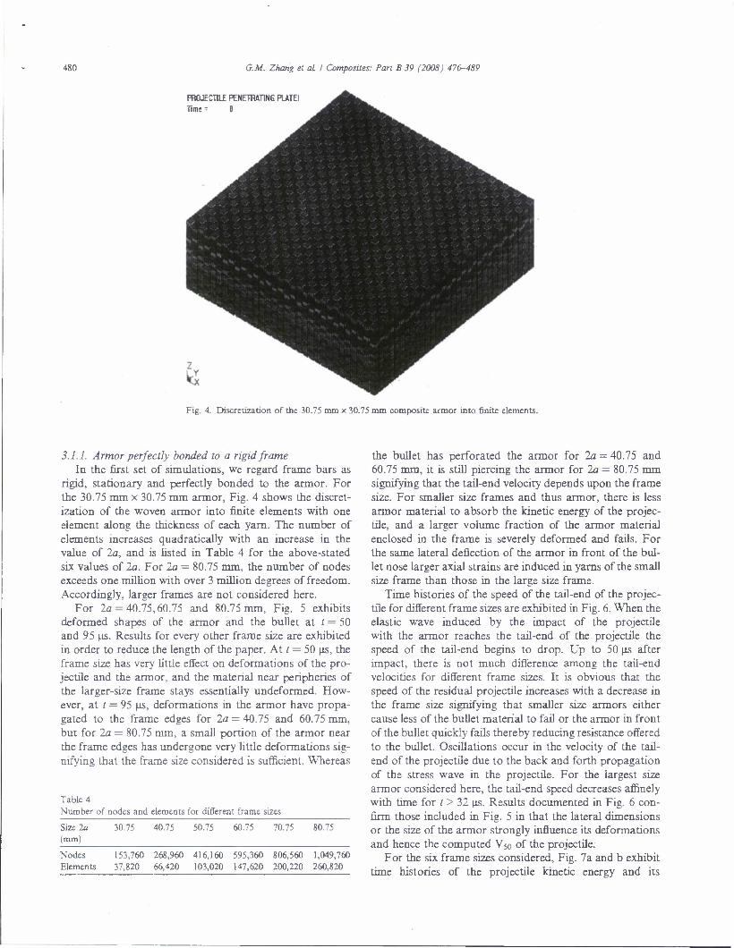
Fig. 4. Discretization of the 30.75 mm x 30.75 mm composite armor into finite elements.
3.1.1. Armor perfectly bonded to a rigid frame In the first set of simulations, we regard frame bars as
rigid, stationary and perfectly bonded to the armor. For the 30.75 mm x 30.75 mm armor, Fig. 4 shows the discret- ization of the woven armor into finite elements with one element along the thickness of each yarn. The number of elements increases quadratically with an increase in the value of la, and is listed in Table 4 for the above-stated six values of la. For la = 80.75 mm, the number of nodes exceeds one million with over 3 million degrees of freedom. Accordingly, larger frames are not considered here.
For la = 40.75,60.75 and 80.75 mm, Fig. 5 exhibits deformed shapes of the armor and the bullet at / = 50 and 95 (is. Results for every other frame size are exhibited in order to reduce the length of the paper. At t = 50 us, the frame size has very little effect on deformations of the pro- jectile and the armor, and the material near peripheries of the larger-size frame stays essentially undeformed. How- ever, at t = 95 us, deformations in the armor have propa- gated to the frame edges for la = 40.75 and 60.75 mm, but for la = 80.75 mm, a small portion of the armor near the frame edges has undergone very little deformations sig- nifying that the frame size considered is sufficient. Whereas
Table 4
Number of nodes and elements for different frame sizes
Size 2a (mm)
30.75 40.75 50.75 60.75 70.75 80.75
Nodes Elements
153,760 268,960 416,160 595,360 806,560
37,820 66,420 103,020 147,620 200,220
1,049,760
260,820
the bullet has perforated the armor for la = 40.75 and 60.75 mm, it is still piercing the armor for la = 80.75 mm signifying that the tail-end velocity depends upon the frame size. For smaller size frames and thus armor, there is less armor material to absorb the kinetic energy of the projec- tile, and a larger volume fraction of the armor material enclosed in the frame is severely deformed and fails. For the same lateral deflection of the armor in front of the bul- let nose larger axial strains are induced in yarns of the small size frame than those in the large size frame.
Time histories of the speed of the tail-end of the projec- tile for different frame sizes are exhibited in Fig. 6. When the elastic wave induced by the impact of the projectile with the armor reaches the tail-end of the projectile the speed of the tail-end begins to drop. Up to 50 us after impact, there is not much difference among the tail-end velocities for different frame sizes. It is obvious that the speed of the residual projectile increases with a decrease in the frame size signifying that smaller size armors either cause less of the bullet material to fail or the armor in front of the bullet quickly fails thereby reducing resistance offered to the bullet. Oscillations occur in the velocity of the tail- end of the projectile due to the back and forth propagation of the stress wave in the projectile. For the largest size armor considered here, the tail-end speed decreases affinely with time for t > 32 us. Results documented in Fig. 6 con- firm those included in Fig. 5 in that the lateral dimensions or the size of the armor strongly influence its deformations and hence the computed V50 of the projectile.
For the six frame sizes considered, Fig. 7a and b exhibit time histories of the projectile kinetic energy and its

G.M. Zhang el al I Composites: Part B 39 (2008) 476-489 481
PROJECTIIE PENETRATING PUTEI Time - 4.999«e-MIS
PnOJEOILE PENETRATING PUTEl Time - «3S99e-aD5
PROJECTILE PENETRATING PUTEl Time - 4.9999HI05
7
PROJECTILE PENETRATING PLATtl Time- 9.51 (Ue-0D&
PROJECTILE PENETRATING PLATEl Time • 9.<935e-005
PROJECTILE PENETRATING PUTEl Time -- S.«S4c-005
'Vlb.^ ' f
* {V-,. *
z z b< k_x
Fig. 5. Deformed shapes of the armor and the projectile at (a) 50 \is and (b) 95 (is for three different frame sizes (from left to right) 40.75 mm, 60.75 mm and 80.75 mm.
-. 320 -
40 60 Time (|js)
Fig. 6. Time histories of the speed of the tail-end of the projectile for different frame sizes.
residual mass. For t > 50 LIS both the projectile mass and the projectile kinetic energy decrease with an increase in the frame size. Assuming that projectile's average speed is nearly the same as that of its tail-end, the projectile kinetic energy decreases with an increase in the frame size due to both a decrease in the projectile mass and its speed. That is, the volume of the failed projectile increases with an increase in the frame size. Note that there are no oscilla-
tions in these curves, and the kinetic energy of the residual projectile for the 50.75 mm frame is greater than that for the 60.75 mm frame.
Fig. 8 depicts the relation between the kinetic energy of the projectile that is used up during the penetration process and the frame size. The horizontal solid line represents the initial kinetic energy of the projectile. Nearly 62.5% of the kinetic energy is dissipated during the penetration process for the 30.75 mm frame and this number increases to 92.6% for the 80.75 mm frame. Thus the frame size notice- ably affects the kinetic energy of the residual projectile.
3.2. Armor held by uniform pressure applied to the four-bar frame
As mentioned above, in ballistic experiments, the armor is usually held between the frame bars by uniform pressure applied to them. The applied pressure should be below the compressive strength of the bar material and of the armor, otherwise one of these two will fail prior to the start of the test. Upon impact of the bullet with the armor, the relative movement of the armor between the frame bars will depend upon the applied pressure and the coefficient of friction between the armor and the material of the frame bars. Since steel used for the frame bars has much higher Young's modulus and compressive strength than the yam, it is reasonable to regard the frame bars as rigid. We now investigate the effect of the relative sliding of the armor between the frame bars on armor's deformations.

482 G.M. Zhang et al I Composites: Pan B 39 (2008) 476-489
40 60 Time (us)
Time (us)
Fig. 7. For different frame sizes, time histories of the (a) kinetic energy, and (b) mass of the projectile.
A typical system comprised of a four-bar steel frame, the armor and the bullet employed during ballistic tests is shown in Fig. 9. Each 42 mm long, 6 mm wide and 0.5 mm thick frame bar is divided into uniform 0.5 mm x 0.5 mm x 0.5 mm solid elements. A uniform clamping pres- sure P = 10,25,100,200 or 300 MPa is applied to the frame bars. Note that the frictional force between the frame bars and the armor will not necessarily be uniformly distributed since deformations of the armor between the bars may be inhomogeneous. The finite element mesh in the frame bars will help simulate this variation in the frictional force.
Deformed configurations at / = 20,50,80 and 95 \is and for P = 10,25,100 and 200 MPa (results for P = 300 MPa are not depicted since they are very similar to those for P — 200 MPa) of the projectile and the armor are shown in Fig. 10 for initial bullet speed of 400 m/s. For each one of the four values of the pressure, deformations of
640
'
ctile
(J
o Initial energy of the projectile __ -
„ m " 8 O-480 - _ • •" a. jar a ^ £ 400 -w" o
•a 5 320 o (ft « 240 > a
c 160 5 09 .C K 80
1 i 15 20 25 30
The frame size a (mm) 35
Fig. 8. The variation with the frame size of the reduction in the kinetic energy of the projectile.
Fig. 9. Schematic sketch of the system comprised of the armor, the four- bar frame, and the bullet.
the system are essentially identical at 20 jis, but are different at later times in the following two respects. First, the thick- ness of the composite armor ahead of the bullet is different. With an increase in the pressure applied to the frame bars, more of the armor ahead of the bullet fails. At t = 80 us, the bullet has not perforated the armor for P — 10 MPa, but the bullet nose has come out of the armor for P = 100 and 200 MPa. The second difference is that for smaller values of the clamping pressure P more of the armor material moves towards the center of the frame; this becomes transparent for t > 50 us. This inward motion of the armor facilitates the transverse displacement of the composite ahead of the bullet. At t — 95 (is, the z-displace- ments of the tip of the projectile equal 21.15,22.63, 24.63,25.03 and 26.67mm for P= 10,25,100,200 and

G.M. Zhang et al I Composites: Part B 39 (2008) 476-489 483
3 PROJECTILE PENETRATING PIATEJ ** Ttme = 1J9S7e-fl05
b
PROJECTILE PENETRATING PLATE1 Time • i.31J9e-0US
v; is
PROJECTILE PENETRATING PLATEl Time- I.S93SC-005
k PPDJECTtLE PeNETnATiMC PLATEl PROJECTILE PENETRATING PLATEl
Time - 4.9995e-005 PflCUECTlLE PENETRATING PLATEl Time • 4,999te-O0S
kS ^ vi
>i *%>
PROJECTILE PENETRATING PLATEl
Turn = 14S37C-M5 PHOJECJHE PEKFnUTMG pura
Timr • UHDS
PROJECTILE PENETRATING PLATEl
Time • tAmc-mi PROJECTILE PENETRATING PLAIEI Time" 143391-005
Fig. 10. For pressure (from left to right) P = 10,25,100 and 200 MPa deformed shapes of the armor and the bullet at t = (a) 20 us, (b) 50 us, (c) 80 us, and (d) 95 us.
300 MPa, respectively. Thus the axial displacement of the Time histories of the axial velocity of the tail-end of the projectile increases with an increase in the clamping pres- projectile are illustrated in Fig. 11. It can be seen that with sure applied to the frame bars. an increase in the clamping pressure applied to the frame
484 G.M. Zhang el aL I Composites: Pan B 39 (2008) 476-489
3 640
560
„480 -
40 60 Time (u.s)
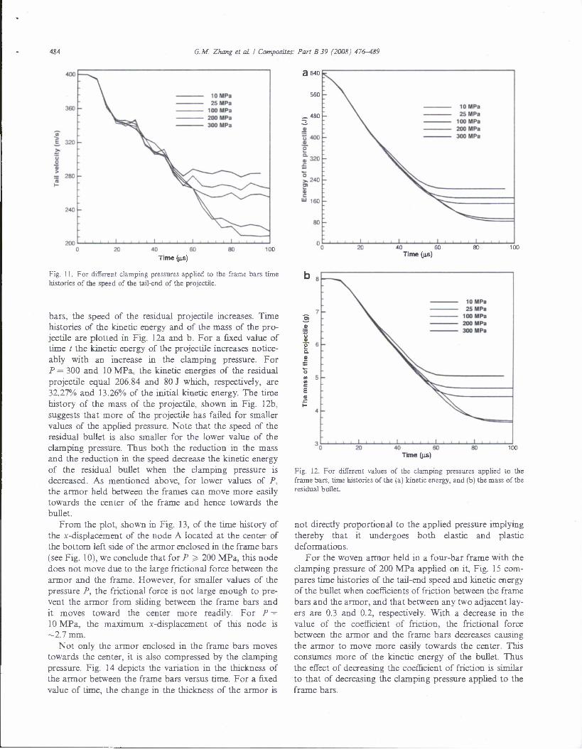
Fig. 11. For different clamping pressures applied to the frame bars time histories of the speed of the tail-end of the projectile.
bars, the speed of the residual projectile increases. Time histories of the kinetic energy and of the mass of the pro- jectile are plotted in Fig. 12a and b. For a fixed value of time / the kinetic energy of the projectile increases notice- ably with an increase in the clamping pressure. For P = 300 and 10 MPa, the kinetic energies of the residual projectile equal 206.84 and 80 J which, respectively, are 32.27% and 13.26% of the initial kinetic energy. The time history of the mass of the projectile, shown in Fig. 12b, suggests that more of the projectile has failed for smaller values of the applied pressure. Note that the speed of the residual bullet is also smaller for the lower value of the clamping pressure. Thus both the reduction in the mass and the reduction in the speed decrease the kinetic energy of the residual bullet when the clamping pressure is decreased. As mentioned above, for lower values of P, the armor held between the frames can move more easily towards the center of the frame and hence towards the bullet.
From the plot, shown in Fig. 13, of the time history of the x-displacement of the node A located at the center of the bottom left side of the armor enclosed in the frame bars (see Fig. 10), we conclude that for P ^ 200 MPa, this node does not move due to the large frictional force between the armor and the frame. However, for smaller values of the pressure P, the frictional force is not large enough to pre- vent the armor from sliding between the frame bars and it moves toward the center more readily. For P = 10 MPa, the maximum x-displacement of this node is ~2.7 mm.
Not only the armor enclosed in the frame bars moves towards the center, it is also compressed by the clamping pressure. Fig. 14 depicts the variation in the thickness of the armor between the frame bars versus time. For a fixed value of time, the change in the thickness of the armor is
40 60 Time (us)
o a. •
o </! </> IB
E a r
40 60 Time (us)
100
Fig. 12. For different values of the clamping pressures applied to the frame bars, time histories of the (a) kinetic energy, and (b) the mass of the residual bullet.
not directly proportional to the applied pressure implying thereby that it undergoes both elastic and plastic deformations.
For the woven armor held in a four-bar frame with the clamping pressure of 200 MPa applied on it, Fig. 15 com- pares time histories of the tail-end speed and kinetic energy of the bullet when coefficients of friction between the frame bars and the armor, and that between any two adjacent lay- ers are 0.3 and 0.2, respectively. With a decrease in the value of the coefficient of friction, the frictional force between the armor and the frame bars decreases causing the armor to move more easily towards the center. This consumes more of the kinetic energy of the bullet. Thus the effect of decreasing the coefficient of friction is similar to that of decreasing the clamping pressure applied to the frame bars.

G.M. Zhang ei aL I Composites: Part B 39 (2008) 476-^89 485
40 60 Time (\is)
100
Fig. 13. For different values of the clamping pressure time histories of the x-displacement of node A.
40 60
Time (us)
100
Fig. 14. For different values of the clamping pressure time histories of the distance between two opposite bars of the frame.
3.3. Armor held by uniform pressure applied to the two-bar frame
We now analyze deformations of the armor held in a two-bar frame; e.g. see Fig. 16. A uniform pressure is applied to the frame bars to hold the armor. Fig. 17 exhib- its deformed configurations of the armor and the penetra- tor at / = 20,50,80 and 95 us. These results are similar to those for the four-bar frame. The two free boundaries facil- itate movement of the armor towards the frame center, and for / > 80 (is, yarns adjacent to one of the frame bars slip out of the frame bars; this slippage was not observed for the armor held in the four-bar frame.
£• 330 o O • > o 300
270 -
^V
0.3
_ 0.2
v\^«
- xr\ _ ^*\\ - \\ - v.
V X^\
V—'—" ^\y^^^"-- ^. .^"y ^- —
** - i 1 , •
100
Time (us)
D 640 !v
V 560 - \\
- \\ ^^ . - 0.3 - V. —. - 0.2
S. 480 - V dl \\ O a. 400 >— \\ a
• \\ \\
O \\ S; 320 \\ a c \\
\\ 240 V\
\\ \\ ^^^^
160 - . , , 1 , , ...1 , ,,,!,,,.
0 20 40 60 80 100 Time (|is)
Fig. 15. For the coefficients of friction equal to 0.2 and 0.3, time histories of the (a) speed of the tail-end, and (b) kinetic energy of the bullet. (The clamping pressure is 200 MPa.)
Fig. 16. A schematic sketch of the armor held in a two-bar frame.

486 G.M. Zhang el ol I Composites: Part B 39 (2008) 476-489
pnojEcniE PENETRATING PLATEI lime -1,9090c-005
PHOJECTILE PENETRATING PLATEl Time - 1.S3D8B-I10S
PROJECTILE PENETRATING PUkTEl Time - 1 1997e-005
«d £5 ss h
V*
PflOJECTILE PENETRATING PLATE. Ttm« - ;.aaa;e-oot
PROJCCT1LC PENETRATING PLATEI Time " K«-00S
*r^ Fig. 17. For pressure P= 10,25,100 and 200 MPa (From left to right) deformed shapes of the armor and the bullet at (a) / = 20 us, (b) 50 us, (c) 80 us,
and (d) 95 us.
For different values of the applied pressure, time histo- ries of the speed of the tail-end of the projectile are depicted in Fig. 18. As for the armor held in the four-bar frame, the speed of the residual bullet increases with an increase in the applied pressure, and it equals ~211,232,253,280 and 192 m/s, for P = 10,25,100,200 and 300 MPa, respectively.
We have plotted time histories of the kinetic energy and the mass of the projectile in Fig. 19a and b. The kinetic energy of the residual bullet increases significantly with an increase in the clamping pressure; nearly 18% more of the initial kinetic energy is consumed during the penetra- tion process when the applied pressure is decreased from

400
360 -
O "S 280
240 -
10 MPa 25MPa
100 MPa 200 MPa 300 MPa
G.M. Zhang el aL I Composites: Part B 39 (2008) 476-489
3 640
487
_J I I I I I i- ?0 40 60
Time ((is)
Fig. 18. For a two-bar frame time histories of the speed of the tail-end of the projectile.
300 to 10 MPa. The time history of the ^-coordinate of the bottom middle node B on armor's front surface (shown in Fig. 16) is given in Fig. 20. For P less than 200 MPa, the frictional force between the composite and the frame bars is not large enough to prevent sliding of the armor between the frame bars.
3.4. Comparison of results for the two frames
We have compared in Table 5 the speed and the kinetic energy of the residual projectile for different pres- sures applied to a frame, and also for the same pressure imposed on the two-bar and the four-bar frames. It is clear that for a given value of the clamping pressure, the speed and the kinetic energy of the residual projectile are less when the armor is held in the two-bar frame than those for the four-bar frame. These trends become more vivid from the plots of Fig. 21a and b.
3.5. Computation of the ballistic limit, V50
We find V50 of the woven composite armor for the fol- lowing four cases: 10 and 200 MPa clamping pressure applied to the two-bar and the four-bar frames. Table 6 gives the kinetic energy of the residual projectile for differ- ent initial speeds when the clamping pressure is 200 MPa and the armor is held in the four-bar frame. It is evident that for initial speeds greater than 275 m/s, the projectile penetrates the target completely. However, for initial speeds less than 270 m/s, the projectile is arrested in the tar- get. Thus the ballistic limit, V50, of the woven armor held in the four-bar frame with a clamping pressure of 200 MPa is between 270 and 275 m/s. We have listed in Table 7 V50 for the four cases. For both the two-bar and the four-bar frames, the V50 decreases by about 30-45 m/s with a decrease in the clamping pressure from 200 to 10 MPa.
40 60 Time (us)
100
Q. 01
40 60 Time (us)
Fig. 19. For different values of the clamping pressure applied to the two- bar frame, time histories of the (a) kinetic energy, and (b) mass of the projectile.
Fig. 22 evinces the reduction in the kinetic energy of the projectile versus its initial kinetic energy. For initial bullet speeds greater than the V50, the kinetic energy absorbed increases almost linearly with an increase in the initial kinetic energy of the projectile, which agrees with Lim's [12] and Zeng's [13] result. However, for initial bullet speed less than 1.5 km/s our computations did not give a sudden additional reduction in the kinetic energy for initial bullet speeds greater than a critical value. It is possible that the critical speed of the bullet is greater than 1.5 km/s.
3.6. Remarks
The element deletion technique used to simulate mate- rial failure may not realistically model material failure. Whereas numerical simulations indicate the Kevlar fiber

4XX G.M. Zhang et aL I Composites: Part B 39 (2008) 476-489
40 60 Time ((is)
Fig. 20. For the two-bar frame, time histories of the ^-displacement of node B for different values of the clamping pressure.
being broken into pieces that can act as projectiles, exper- imental observations suggest this not to be the case. Rather a Kevlar fiber is cut into two pieces in front of the projectile nose resulting in the formation of a pathway for the bullet. It seems that the node splitting technique such as that employed in [15,16] or the use of cohesive zones may be more appropriate for modeling the breakage of Kevlar fiber into two parts.
4. Conclusions
We have numerically simulated three-dimensional defor- mations occurring during the penetration of a 9 mm FMJ, 124 grain projectile into soft body woven armor with the commercial finite element software, LS-DYNA. The pro- jectile core is made of lead and is covered with a thin layer of copper. The geometry of the woven fabric is approxi- mated by discretizing it into weft and warp yarns each of which is taken to be an orthotropic material. Frictional forces between adjoining layers and that between the armor and the frame bars are considered. Failed elements are deleted from the analysis.
We have delineated the effect of the frame size on the speed and the mass of the residual bullet, or equivalendy on the fraction of the initial kinetic energy of the projectile dissipated during the penetration process. The effect of the frame size on the deformations of the projectile and the
a
«" 280 £
TS C 9
= 260 o
o c
f* ?40
o >- u
•2 220 01 >
\&Y — two-bar frame 3 •o - / - four-bar frame a 200
• £. 1-
', , , i i i i 1111111111 I.II.I
220 -
200
a 180
O 140 >>
•a
120
80 -
60 -
50 100 150 200 250
The Clamping pressure (MPa) 300
two-bar frame four-bar frame
0 50 100 150 200 250 300
The Clamping pressure (MPa)
Fig. 21. For the two-bar and the four-bar frames, the (a) speed and (b) kinetic energy of the residual projectile versus the clamping pressure.
armor has been ascertained by first regarding the frame bars to be rigid and the armor perfectly bonded to the square frame. Computed results reveal that for up to 80.75 mm x 80.75 mm frames the V50 decreases with an increase in the frame size. However, we have not deter- mined the minimum frame size so that for frame sizes greater than this value, the V50 will be independent of the frame size.
Table 5 For different values of the clamping pressure, comparison of the speed and the kinetic energy of the residual bullet for the rwo-bar and the four-bar frames
Pressure (MPa) 10 25 100 200 300
Residual velocity (m/s) Two-bar 192.36 210.69 231.98 253.47 280.28 Four-bar 209.78 214.59 260.31 265.29 283.22
Residual kinetic energy (J) Two-bar 68.96 86.44 115.68 149.11 186.91 Four-bar 84.98 94.25 151.17 172.41 206.84

G.M. Zhang et al. I Composites: Part B 39 (2008) 476-489 489
Table 6 The residual kinetic energy of the projectile for different initial velocity
Initial speed Initial kinetic Residual kinetic Perforation (m/s) energy (J) energy (J)
600 1,442.17 759.73 Yes 40(1 640.97 167.02 Yes •50 490.74 96.43 Yes 300 360.55 15.95 Yes 280 314.07 10.03 Yes 275 302.96 1.25 Yes 270 292.04 0.00 No 260 270.81 0.00 No 250 250.38 0.00 No
Table 7 The ballistic limit for the four cases
Clamping pressure (MPa) 10 200
Ballistic limit, V50 (m/s) Two-bar frame Four-bar frame
315-320 315-320
285-290 270-275
a // o 1750 s'
a o
» 150° .£
° 1250 01 a 2 1000 a (C >> O) 750 a c a " 500 ffi e
t 250 .e F
f • • • i . , i i i . , , , 0 2000 4000 6000 8000
The initial kinetic energy of the projectile (J)
Fig. 22. The reduction in the kinetic energy of the projectile versus its initial kinetic energy.
We have also studied the effect on deformations of the armor and the projectile of the clamping pressure applied to the entire surfaces of the two- and the four-bar frames. It is found that an increase in the applied pressure reduces the kinetic energy of the bullet consumed during the defor- mation process. For the same applied pressure the two-bar frame is more effective in resisting the bullet than the four- bar frame.
The speed and the kinetic energy of the residual bullet decrease with a decrease in the coefficient of friction
between the frame bars and the armor, and between adja- cent layers of the armor. This effect is similar to decreasing the clamping pressure applied to the frame bars.
For the four-bar 42 mm x 42 mm frame clamped with a pressure of 200 MPa the V50 is found to be ~270 m/s, and it decreases with an increase in the clamping pressure.
Disclaimer: Views expressed herein are those of authors and neither of the US Army nor of Virginia Polytechnic Institute and State University.
Acknowledgement
This work was supported by the office of Naval Research grant NOOO14-05-1-0826 to VPI&SU.
References
[1] Duan Y, Keefe M, Bogetti TA, Cheeseman BA. Modeling friction effects on the ballistic impact behavior of a single-ply high-strength fabric. Int J Impact Eng 2005;31:996-1012.
[2] Cheeseman BA, Bogetti TA. Ballistic impact into fabric and compliant composite laminates. Compos Struct 2003;61:161-73.
[3] Shockey DA, Erlich DC, Simons JW. Improved barriers to turbine engine fragments: interim report m. US Department of Transpor- tation Federal Aviation Administration Report, DOT/FAA/ER-99/ 8, m, May, 2001.
[4] Lee BL, Walsh TF, Won ST, Parts HM. Penetration failure mechanism of armor-grade fiber composites under impact. J Compos Mater 2001;35:1605-33.
[5] Shim VPW, Tan VBC, Tay TE. Modeling deformation and damage characteristics of woven fabric under small projectile impact. Int J Impact Eng 1995;16:585-605.
[6] Billon HH, Robinson DJ. Models for the ballistic impact of fabric amour. Int J Impact Eng 2001;25:411-22.
[7] Tan VBC, Ching TW. Computational simulation of fabric armour subjected to ballistic impacts. Int J Impact Eng 2006;32:1737-51.
[8] Barauskas R, Abraitiene A. Computational analysis of impact of a bullet against the multi-layer fabrics in LS-DYNA. Int J Impact Eng 2007;34:1286-305.
[9] Gu B. Ballistic penetration of conically cylindrical steel projectile into plain-woven fabric target—a finite element simulation. J Compos Mater 2004;38:2049-74.
[10] Parga-landa B, Hernandez-olivares F. An analytical model to predict impact behaviour of soft armours. Int J Impact Eng 1995;16:455-66.
[11] Sun CT, Potti SV. A simple model to predict residual velocities of thick composite laminates subjected to high velocity impact. Int J Impact Eng 1996;18:339-53.
[12] Lim CT, Shim VPW, Ng YH. Finite-element modelling of the ballistic impact of fabric armor. Int J Impact Eng 2003;28:13-31.
[13] Zeng XS, Tan VBC, Shim VPW. Modeling inter-yarn friction in woven fabric armour. Int J Numer Meth Eng 2006;66:1309-30.
[14] LS-DYNA Keyword User's Manual, Version 970, Livermore Soft- ware Technology Corporation, April 2003.
[15] Batra RC, Love BM. Crack propagation due to brittle and ductile failures in microporous thermoviscoplastic functionally graded materials. Eng Fract Mech 2005;72:1954-79.
[16] Batra RC, Lear MH. Simulation of brittle and ductile fracture in an impact loaded prenotched plate. Int J Fract 2004;126:179-203.

EFFECT OF MATRIX ON THE BALLSITIC PERFORMANCE OF SOFT BODY ARMORS
G. Gopinath1, J. Q. Zheng2 and R. C. Batra1
'Department of Engineering Science & Mechanics, M/C 0219, Virginia Polytechnic Institute and State University, Blacksburg, VA 24061
2Program Executive Office - Soldier, US Army, 15395 John Marshall Highway, Haymarket, VA
20169, United States
Abstract We study three dimensional deformations of a body armor composed primarily of Kevlar yarns and a small volume fraction of matrix, and account for their failure. The goal is to provide an improved understanding of different failure mechanisms and the effect of the volume fraction of the matrix material, and the bonding between the matrix and the yarn on the impact resistance of the armor.
1. Introduction
Body armors made of woven fabric composites are extensively being used by the military and other law enforcement agencies to protect their personnel. Apart from preventing the projectile from penetrating, the vest must also be designed so that there is no noticeable bulge at the back face as this would lead to significant injuries even if the projectile does not completely penetrate the armor. The bulge height can be reduced by incorporating a layer of very soft fibrous material [1] between different armor layers. During penetration yarns which engage the projectile directly are called the principal or primary yarns. These yarns absorb most of the energy during impact and hence are the first to fail. Fibers possessing high strength and failure strain can absorb more energy before failing and hence form ideal candidates for use in fabric. Secondary yarns are those which do not come in direct contact with the projectile, and the amount of energy absorbed by these yarns is limited. It is intuitive to see that the ballistic performance of a body armor is improved if not only more yarns can engage the projectile during penetration but also disperse the stress waves away from the point of contact. Roylance [2] through numerical simulations showed that increasing friction between yarns leads to an increase in dispersion of stress waves. This was also shown to be true from experimental investigations by Briscoe and Motamedi [3] and through finite element simulations by Duan et al.[9]. Lee et al. [4] have studied the effect of matrix resin on the performance of fabric composites. Though the amount of matrix present in such composites is very small (typically in the range of 20-25% by volume) they can significantly influence the performance of the body armor. The presence of matrix has two important consequences; it not only restrains the yarns from moving but also helps in coupling different yarns together. Evidence for the above phenomena was given through a series of load deflection experiments and postmortem inspections conducted by Lee et al. [4]. Load deflection curves indicated that during penetration of the composite laminates there was a sudden drop in load after the failure whereas for armors made of only yarn fabric the load gradually dropped. The gradual load decrease was attributed to yarn slippage and successive breakage of individual yarns. Photographic evidence of the damaged area showed that more yarns were engaged for composites when compared to laminates made of only yarns. Also,

smaller penetration radius was observed for body armors made of only yarns as compared to laminates made of composites. Another consequence of having the matrix is that the effect of taper/curvature of the projectile on penetration is greatly reduced. It must be noted that the amount of energy absorbed by the resin material during penetration is only marginal. The above discussion may lead one to believe that the presence of matrix helps improve the ballistic performance, but this is not always the case as the matrix tends to make the body armor less flexible and hence the depth of the cone formed during penetration would be reduced leading to a less amount of energy absorbed. Also, the loss in flexibility can lead to reduced interaction between different layers of the fabric composite and it has generally been observed that laminates that have weak or no interaction tend to absorb less energy as compared to those that interact with each other [5,6,7]. Cheeseman and Bogetti [8] have suggested that very weak interaction between the matrix and yarn is preferable as it facilitates delamination between the matrix and the yarn allowing the fibers to extend to failure.
The presence of matrix on the ballistic performance of soft body armor has not been thoroughly studied in the literature, and conclusions have been drawn from results of a few experimental investigations such as that of Lee et al. [4]. The presence of matrix has two competing influences; on one hand it engages more yarns and prevents their sliding thereby increasing the ballistic performance of the body armor, on the other, it reduces the flexibility and the interaction among various layers thereby reducing the ballistic performance. We study this problem more comprehensively through numerical simulations as it is easier to assess results based on parameters that can be controlled. The problem is investigated by considering the impact of a hemispherical nosed cylindrical projectile consisting of a copper shell filled with lead on a woven composite made of Kevlar fabric and matrix resin. The effect of stiffness of the laminate on the ballistic performance is studied by considering polymers having different elastic moduli. The effect of bond strength between the matrix resin and the yarn fabric is also considered. The present investigation clearly shows how the matrix properties and the laminate stiffness significantly influence the overall performance of the body armor.
Though woven fabric has been previously modeled as one-dimensional (ID) or as 2D shell elements the use of 3D solid elements offers a more realistic view during the projectile penetration accounting for friction, and failure mechanisms etc. [10, 11]. Hence a more computationally intensive 3D finite element simulation using the commercial computer code LSDYNA has been carried out.
The rest of the paper is organized as follows. Section 2 describes the material and the geometric parameters of the armor and the projectile, constitutive relations, the failure criteria, and values assigned to different parameters. Results from simulations delineating effects of matrix properties on deformations and failure of the body armor are presented in Section 3.
2. Material and geometric parameters
Commercial packages ABAQUS, ETA-VPG and LS-PREPOST were used for pre- processing the data. Figure 1 shows the woven composite with matrix resin and a representative volume element (RVE) of the composite laminate. The RVE exhibits distribution of the polymer matrix between the adjoining layers. Kevlar yarn bundle is modeled as a 3D continuum and

meshed with eight-node brick elements. The width and the thickness of the yarn bundle were taken to be 1.0 mm and 0.75 mm, and no gap is assumed between yarn crossovers (this simplifies the geometric structure of the resin matrix and its finite element mesh). The volume fraction of the polymer in the RVE was found to be 15.5%. The polymer matrix was meshed with tetrahedral elements, and six layers of 75 mm x 75 mm composite laminates were used in the simulations. A gap of 0.1 mm is maintained between different layers and the overall thickness of the composite is about 9.5 mm. Simulations were performed by constraining the degrees of freedom of the end nodes of different layers of the laminates while the projectile penetrated the composite.
Material properties of the yarn are assumed to be strain rate independent since there is a lack of experimental data to realistically model this behavior. The material model MATCOMPSOTEDAMAGE available in LSDYNA is used to simulate the mechanical response of the yarn. Values of material properties taken from [10] are listed in Table 1.
MATRIX -* YARN
Figure 1: Woven fabric composite, and a representative volume element

Table 1: Material parameters for the Kevlar yarn fabric
Mass density, p = 1440 kg/m ; Elastic moduli, Ea = 164.0 GPa; Eb = Ec = 3.28 GPa; Poisson's ratio, (ia= Hb = M-c =0; Shear moduli, Gab = Gbc = Gca = 3.28 GPa Shear strength in the ab-plane = 1.886 GPa; Longitudinal tensile strength along a-axis = 2.886 GPa; Transverse tensile strength along b-axis = 1.486 GPa; Transverse compressive strength along b-axis =1.7 GPa; Normal tensile strength along c-axis = 1.486 GPa; Transverse shear strength in ca-plane = 1.586 GPa; Transverse shear strength in cb-plane = 1.886 GPa.
Here a-axis is aligned along the yarn, b-axis transverse to the yarn in the plane of the layer, and the c-axis is along the normal to the ab-plane.
The yarn is assumed to fail at a principal strain of 0.2, and the option MAT_ADD_EROSION in LSDYNA is used to remove failed yarn elements from the calculations. This eliminates severely distorted elements from the finite element mesh, maintains reasonable time step size and enables simulations run for a longer time.
The polymer matrix is assumed to be isotropic and modeled using the material model MATPrECEWISELINEAR PLASTICITY in LSDYNA. We have specified the yield stress and the tangent modulus of the material. To see how the matrix properties affect the ballistic performance we have considered three sets of data to mimic a soft, moderately stiff and a very stiff polymer. Values of material parameters, listed below, have been arbitrarily chosen and may not correspond to any real material.
Mass density, p = 900 kg/m ; Elastic modulus, Ei = 0.5 GPa; Poisson's ratio, (j.i=0.35; yield stress, cyi=20Mpa Elastic modulus, E2 = 3.5 GPa; Poisson's ratio, ji2=0.35; yield stress, ay2=50Mpa Elastic modulus, E3 = 7.0 GPa; Poisson's ratio, ^3=0.35; yield stress, ay3=75Mpa
The failure strain (plastic) for each matrix is taken to be 0.05, and the tangent modulus equal to one-half the elastic modulus. The Cowper-Symonds relation is used to include the effect of strain rate with
C= 4000s; P=0.182
To study the effect of matrix adhesion with the yarn we have considered two extreme cases. Tie constraints are imposed between the yarns and the matrix to represent perfect bonding and no constraints to represent no adhesion.
The projectile used is 13.3 mm long 9 mm Remington full metal jacket (FMJ), and is comprised of 0.5 mm thick outer copper layer with a solid lead shot filling. The values of

geometric and material parameters, identical to those used in Zhang et al. [10], are briefly summarized next. The Johnson-Cook (JC) relation incorporating damage is used to simulate the thermo-viscoplastic response of copper, and lead is modeled as an elastic perfectly plastic material; each material is assumed to be isotropic. Values assigned to different parameters are listed in Table 2.
Table 2: Values of material parameters for copper and lead in the penetrator
Values of material parameters for copper in the JC constitutive relation
A = 0.09GPa; B = 0.292 GPa; C = 0.025 n = 0.31;m =1.09; Mass density = 8950 kg/m3
Specific heat = 385 J/kg K Shear modulus = 47.27 GPa Bulk modulus = 102.4 GPa Di 1.0 D2=1.0;D3 = 0;D4 = 0;D5 = 0 Tm = 1356 K;Ospau= 1.9 GPa
Material parameters for lead
Mass density =11,340 kg/m3
Elastic modulus = 16 GPa Poisson's ratio = 0.44 Yield stress =0.383 GPa Failure strain = 0.3
3.1 Projectile impacting a single layer
We first study the impact resistance of a single layer composite/yarn system to see how the matrix can influence its performance. Figure 2 exhibits the time history of the kinetic energy (KE) of the projectile for an initial velocity Vo = 100 m/sec; the soft and the stiff matrix refer to polymers with material properties indicated above by subscripts 1 and 3 respectively. It is evident that the three curves are close to each other signifying that the matrix mechanical properties have a little influence upon the decrease with time of the projectile's KE. The maximum decrease in the KE of the projectile for the time durations considered is for the composite with the stiff matrix and differs from that of the no matrix case by 12%. However, eventually at 200 us, the fiber only layer absorbs the most KE of the projectile. Also, there is only a marginal difference in the decrease in projectile's KE for composites containing the soft and the stiff matrices (for the cases being considered tie- constraints have been imposed between the matrix and the yarn). With time, however, the laminate made of only yarns continues to absorb energy before it fails whereas for the composite laminate failure starts to occur much earlier with limited amount of energy absorption. Thus the residual velocity of the projectile is much lower for the laminate made of only yarns as compared to the laminate having matrix. The primary reason for is that the addition of polymer makes the composite laminate less-flexible and it does not stretch as much as the laminate made of only yarns. This is also confirmed by comparing plots of the

45
40
35
OS
.2 30 s
O 25 « z N U —
20
S 1SH
10
Vo=100m/sec
•NO MATRIX
'SOFT-MATRIX
STIFF-MATRIX
50 100 TIME (micro seconds)
150 200
Figure 2: Time history of the KE of the projectile impacting a single layer composite.
deformed laminates exhibited in Figure 3. The cone formed in the laminate made of only yarns is deeper than that in the laminate containing matrix resin. At 200 us the lamina made of only yarn has not completely failed so further reduction in the KE of the projectile is possible as compared to the laminate containing matrix in which the projectile has penetrated through the lamina. Even though the flexibility of the laminate made of only yarn has allowed it to absorb more energy, the cone formed is deeper too and that may adversely affect soldier's protection from getting injured.

3BSaBBdB03
BOB 3L
CONE FORMATION MATTON
a. Laminate made of only yarn b. Laminate made of yarn and matrix
Figure 3. Comparison of contour plots of the transverse displacement at 200 us.
3.2 Projectile impacting a multi-layer composite system
Figure 4 shows the time history of the KE of the projectile as it penetrates a six-layer
composite system. Cases marked adhesion and no-adhesion refer, respectively, to simulations in
which tie-constraints have and have not been imposed between the matrix and the yarn. These
results suggest that the residual velocity of the projectile decreases with an increase in the
stiffness of the matrix, an enhancement in the bonding between the yarn and the matrix, and an
increase in the material moduli of the matrix.

400
20 40 60 80 100
TIME (micro seconds)
120 140
Figure 4. Time history of the KE of the projectile impacting a six-layer composite.

20 40 60 80 100 TIME (micro seconds)
120 140 160
a. Total energy absorbed by yarn

60
50
> O W 30
- g20
10
Vo =300 m/sec
j^flr^- SOFT MATRIX (NO ADHESION)
JF^ —•— SOFT MATRIX (ADHESION)
^JP* —*— STD7F MATRIX (NO ADHESION)
: —*— STIFF MATRIX (ADHESION)
—*— VERY STIFT MATRIX (NO ADHESION)
$$r
—•— VERY STIFF MATRK (ADHESION)
20 40 60 80
TIME (micro seconds)
100 120 140
b. Total energy absorbed by the matrix
Figure 5. Time history of the total energy absorbed by the laminates
In order to understand how the matrix influences the performance of the body armor we
have plotted in Figures 5a and 5b time histories of the total energy ( TE = KE + EE) for all layers
of yarn. The TE of laminates made of only yarns shows the greatest amount of energy absorbed
during penetration. Also, for composites in which tie constraints have been imposed between the
matrix and the yarn show less energy absorption as compared to that for composites in which no
constraints have been imposed. This indicates that apart from restricting the motion of yarns during penetration the matrix in the composite also prevents the complete extension of the yarn
before failure. This is also borne out by the fact that the matrix in those laminates which are
strongly bonded to the yarns show marginally higher amount of energy absorption. As expected (see Fig. 6), laminates made of soft matrix material have a larger damage zone as compared to
that in the laminate with stiff matrix material. In the absence of any matrix the number of yarns

which engage the projectile during penetration is limited to a small zone around the area of contact. The interaction between various yarns in this case is primarily through friction. The matrix resin allows for coupling between the yarns and hence a larger zone engages with the projectile. Apart from the coupling action, it also constrains the yarns from slipping. It is seen that the peak transverse displacement for laminates with no matrix is the largest, and it decreases with an increase in the stiffness of the matrix. Also, yarns being displaced are concentrated close to the point of contact for composites made of only yarn whereas for laminates with matrix the zone of influence is much larger and increases with the stiffness and the application of tie constraints.
• R_» ft B & • & a b • t* k *,8 «,».».«„•»,•.* • • a a B s s.i mai
aV« Va Vs> V« VaVs'a V* W'IVB *»*»* -*- *
*»'* a** V«V*Vw'a'«***« ni>»ci- liliBi a'3 a «V»V"'Ji wtxmttmttBt. X\ -r_aaa a a a a a'asa «"is "«• s'?i B r;r
'fc**aBnfc3 2»aIII
riiitiniiriBiii
rf'.- :#
•rfw) m
I?*'
. • •i••aai
IIVSVBVIIVIJ ar'a'a a «.a.* a a fl.sr.a.a.a BE • wn._*.&.* » • » a * a1'*"! :".":" '. ' ••"•.•• • ; ;.'.'•; • •,:•.:.;:-> .:.'•.•.:...
a'a'aVc'aVa VaVat»,» * a^a.w.a* *.«,*.*. V*.*.* *•*, *•*,•*,» a *Y»V**aVaVa*«*»; at
Composites made of only yarn

Stiff matrix with no adhesion Stiff matrix with adhesion
b
^•^•"t'w'M'KSw^aitM^B'M^B'B'BSSga^y^K^w'Kjag**
Very stiff matrix with no adhesion Very stiff matrix with adhesion
c
Figure 7: Damage plots for composites (T=80usec, Vo=300m/sec)

It was found that composites having soft matrix performed poorly primarily because the
matrix fails rather easily and hence is unable to couple different yarns together. Additionally,
there is also a loss in flexibility due to the presence of matrix. This was verified by running a
simulation in which the failure strain for the matrix was increased from 0.05 to 0.10. As
evidenced by results exhibited in Fig. 8, there is a noticeable decrease in the KE of the projectile
when the failure strain for the matrix is doubled.
400
350
300
^250 01
o 1-9
>-> fc 200 e i)
"3 a X 150 •
Vo =300 m/sec
100 •
50
SOFT MATRIX (ADHESION>5% FAILURE
SOFT MATRIX (ADHESION)-10% FAILURE
NO MATRIX
20 40 60 80
TIME (micro sec)
•
100
i
120 140 160
Figure 8: Effect of increase in failure strain

4. Conclusions
The matrix in a composite significantly influences the ballistic performance of body
armors because it decreases the flexibility of the armor and hence yarns are unable to stretch as
much as they can without the matrix. A weak adhesion between the matrix and the yarn enables
more yarns to stretch to their limiting values. However, the coupling and the constraining effects
of the matrix on the yarns outweigh the loss in flexibility and improve body armor's
performance. An increase in the material moduli of the polymer matrix enhances armor's
performance. If trends seen in simulations with six layers hold when the number of layers is
increased, then one would expect that the matrix would further magnify its influence on the
ballistic performance for a composite with several layers.
References
1. J S. Bazhenov, Dissipation of energy by bulletproof aramid fabric, J. of material science, 32, 1997,4167-4173.
2. D. Roylance, Stress wave propagation in fibers: effect of crossovers, Fiber science and
technology, 13, 1980, 385-395.
3. Briscoe and Motamedi, The ballistic impact characteristics of aramid fabrics: the influence of interface friction, Wear, 1992, 158(1-2), 229-47.
4. B. L. Lee, et al., Penetration failure mechanisms of armor-grade fiber composites under
impact, J. of composite materials, 35,2001.
5. M. R. Ahmad, et al., Effect of fabric stitching on ballistic impact resistance of natural rubber coated fabric systems, Materials and Design, 29, 2008, 1353-1358.
6. M.V. Hosur et al., Performance of stitched/unstitched woven carbon/epoxy composites under high velocity impact loading, Composite Structures, 64, 2004, 455^4-66.
7. C.T. Lim et al., Perforation of high-strength double-ply fabric system by varying shaped projectiles, Int. J. of Impact Engineering, 27, 2002, 577-591.
8. B. A. Cheeseman and T. A. Bogetti, Ballistic impact into fabric and compliant composite
laminates, Composite Structures, 61, 2003, 161-173.
9. Y. Duan et al., A numerical investigation of the influence of friction on energy absorption by a
high-strength fabric subjected to ballistic impact, Int. J. of Impact Engineering, 32, 2006, 1299— 1312.
10. G.M. Zhang et al., Effect of frame size, frame type, and clamping pressure on the ballistic
performance of soft body armor, Composites: Part B, 39, 2008, 476-489.

11. B. Gu, Ballistic penetration of conically cylindrical steel projectile into plain-woven fabric target - a finite element simulation, J. of composite materials, 38, 2004, 2049-2074.
12. LSDYNA Keyword user's manual (version 971).
13. A. Arias et al., Numerical modeling of the impact behavior of new particulate-loaded composite materials, Composite Structures, 61, 2003, 151-159.