report lab 1
DESCRIPTION
472TRANSCRIPT
Report Lab 1
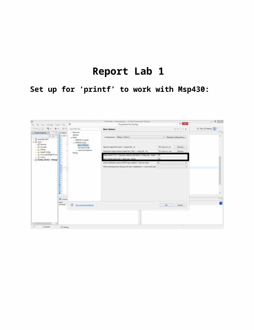
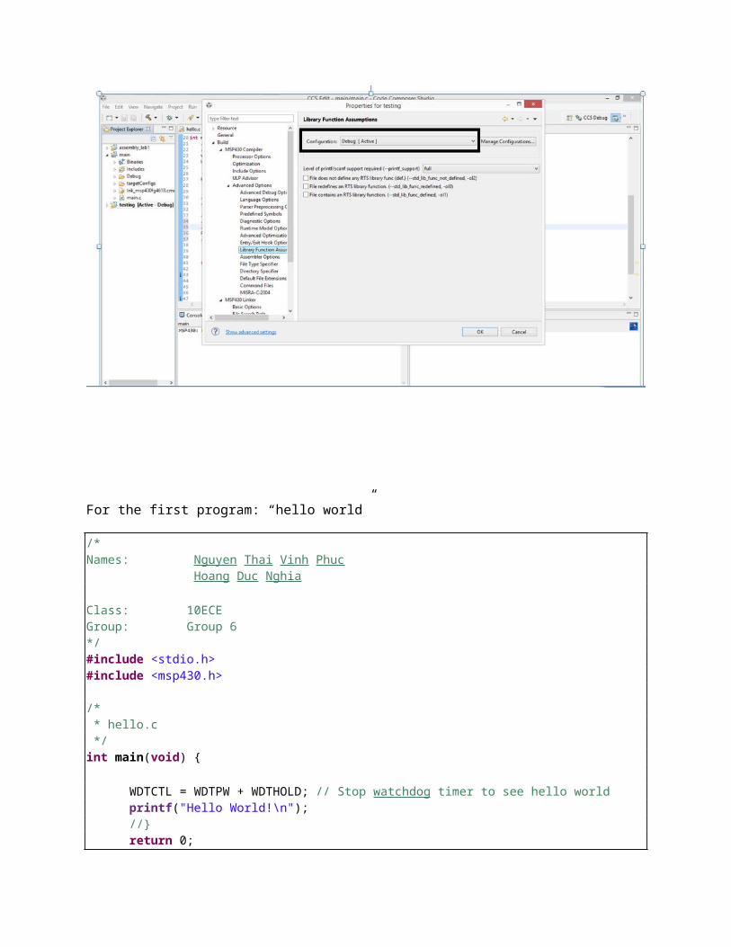
Set up for ‘printf’ to work with Msp430:
For the first program: “hello world”
/*Names: Nguyen Thai Vinh Phuc Hoang Duc Nghia Class: 10ECEGroup: Group 6*/#include <stdio.h>#include <msp430.h>
/* * hello.c */int main(void) {
WDTCTL = WDTPW + WDTHOLD; // Stop watchdog timer to see hello worldprintf("Hello World!\n");//}return 0;
}
For the first program: “hello world” with loop
/*Names: Nguyen Thai Vinh Phuc Hoang Duc Nghia Class: 10ECEGroup: Group 6*/#include <stdio.h>#include <msp430.h>
/* * hello.c */int main(void) { // WDTCTL = WDTPW | WDTHOLD; // Stop watchdog timer
WDTCTL = WDTPW + WDTHOLD; // Stop watchdog timer so thefor(;;)// infinite loop{printf("Hello World!\n");}return 0;
}
For assembling code(sample blinking 1 )

;-----------------------------------------------------------------------;Name: GROUP 6: NGUYEN THAI VINH PHUC && HOANG DUC NGHIA;Group 6;----------------------------------------------------------------------- .cdecls C,LIST, "msp430fg4618.h" ; Include device header file .text ; Assemble into program memory .global _START ; define entry point
START mov.w #0x300,SP ; Initialize 0x1200 StopWDT mov.w #WDTPW+WDTHOLD,&WDTCTL; Stop watchdog timerSetupP1 bis.b #004h,&P2DIR ; P2.2 direction = 1Mainloop xor.b #004h,&P2OUT ; Toggle P2.2
Wait mov.w #0xA000,R7 ;delay R7 //0x0005 for checking debug funtionL1 dec.w R7 ; Decrement R7 jnz L1 ; Delay over? jmp Mainloop ; Again .sect ".reset" ; MSP430 RESET Vector .short START .end
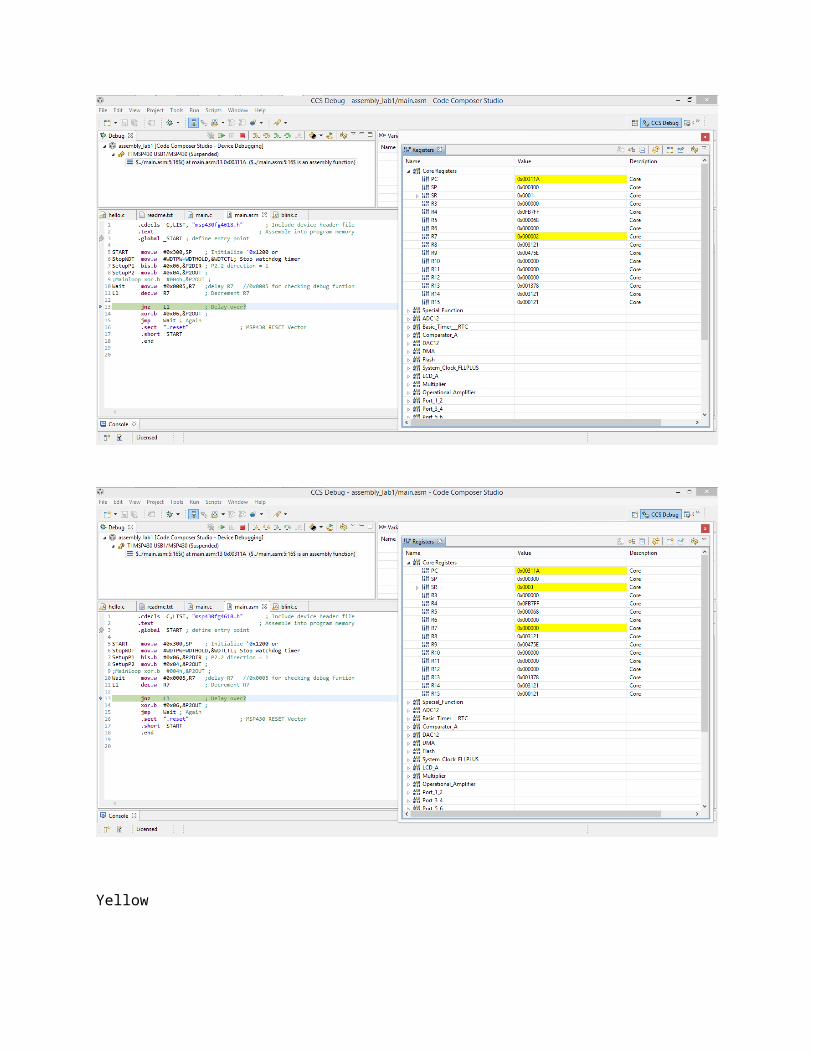
As seen below, the location of program C is in program flash memory where the instructions are located.

As seen below, debugging a program is the Register window.
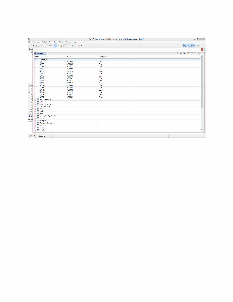

5. Modify the assembly language program to load a value of 0x0005 into register R7. Build the project and then debug this project. Next, trace through each line of the code using the Step Into option observing the register values as each line of code is executed. In particular, take note how R7 starts with a value 0x0005 and decreases in value until it reaches zero. For R7=0x0005;Then press F5 to go step by step for debug.


1. Modify and execute the C-language program so that both the green and yellow LEDs blink alternatively on and off about once every second. For one second, the green LED is on and the yellow LED is off. For the next second, the green LED is off and the yellow LED is on. Adjust the value used in the delay loop to obtain the correct timing. Make sure that this program is properly commented. An additional for loop may be needed to obtain the desired timing. Make sure to have the lab assistant verify the functionality of this program.

/*Names: Nguyen Thai Vinh Phuc Hoang Duc Nghia Class: 10ECEGroup: Group 6*/
//#include <msp430.h>//*********************************************************************// LED turn on and off to blink the LED on Port 2 of the MSP430FG4618// experimenter board RAM at 0x1100 - 0x30ff, FLASH at 0x3100 –// 0xfbff// Port 2 is used for the LED's Port 2 bit 2 is the green LED,// Port 2 bit 1 is the yellow LED// input buttons on port 1 bits SW1 = bit 0 and SW2 = Bit2// 1 = SW not pressed 0 = pressed//*********************************************************************//---------------------------------------------------------------------// must include the C header to get the predefined variable names// used by the MSP430FG4618 on the experimenter board//---------------------------------------------------------------------#include "msp430fg4618.h"//#include "stdio.h"/* * main.c */int main(void) {
// tell the compiler not to optimize the variable I, otherwise the// compiler may change how the variable is usedvolatile unsigned int i;WDTCTL = WDTPW + WDTHOLD; // Stop watchdog timer so the // program

// runs indefinitelyP2DIR |= 0x06; // Set port 2 bit 1 to as an
XANH // output; 1 = output 0 = input// turn the light on// set initial led for green and yellow led//Port 2 bit 2 is the green LED and Port 2 bit 1 is the yellow LEDP2OUT=0x04;
//For one second, the green LED is on and the yellow LED is off. for initial condition
// go run the program foreverfor (;;){ // delay before turning changing the state of the LED for(i=0;i<=10000;i++);// 1 second approximately
P2OUT = P2OUT ^ 0x06; // X xor 1 =!x
}}
Press F5 to go step by step for seeing what happens inside registers.
Green:
For the delay:

Yellow:

2. Repeat step 1, but this time modify and execute the assembly language program. An additional loop may be needed to obtain the desired timing for second on and one second off. For debug: R7: 0005h
Press F5 to go step by step for seeing what happens inside registers.
;-----------------------------------------------------------------------;Name: GROUP 6: NGUYEN THAI VINH PHUC && HOANG DUC NGHIA;Group 6;----------------------------------------------------------------------- .cdecls C,LIST, "msp430fg4618.h" ; Include device header file .text ; Assemble into program memory .global _START ; define entry point
START mov.w #0x300,SP ; Initialize 0x1200 orStopWDT mov.w #WDTPW+WDTHOLD,&WDTCTL ; Stop watchdog timerSetupP1 bis.b #0x06,&P2DIR ; P2.2 direction = 1SetupP2 mov.b #0x04,&P2OUT ; Green ON; Red off
main mov.w #0x0005,R7 ;delay R7 //0x0005 for checking debug funtionL1 dec.w R7 ; Decrement R7
jnz L1 ; Delay over? xor.b #0x06,&P2OUT ; jmp main ; Again .sect ".reset" ; MSP430 RESET Vector .short START .end
Green


Yellow
;-----------------------------------------------------------------------;Name: GROUP 6: NGUYEN THAI VINH PHUC && HOANG DUC NGHIA;Group 6;----------------------------------------------------------------------- .cdecls C,LIST, "msp430fg4618.h" ; Include device header file .text ; Assemble into program memory .global _START ; define entry point
START mov.w #0x300,SP ; Initialize 0x1200 orStopWDT mov.w #WDTPW+WDTHOLD,&WDTCTL ; Stop watchdog timerSetupP1 bis.b #0x06,&P2DIR ; P2.2 direction = 1SetupP2 mov.b #0x04,&P2OUT ; Green ON; Red off
main mov.w #0xA000,R7 ;delay R7 //0x0005 for checking debug funtionL1 dec.w R7 ; Decrement R7
jnz L1 ; Delay over? xor.b #0x06,&P2OUT ; jmp main ; Again .sect ".reset" ; MSP430 RESET Vector .short START .end

As seen below, the location of program C is in program flash memory where the instructions are located.
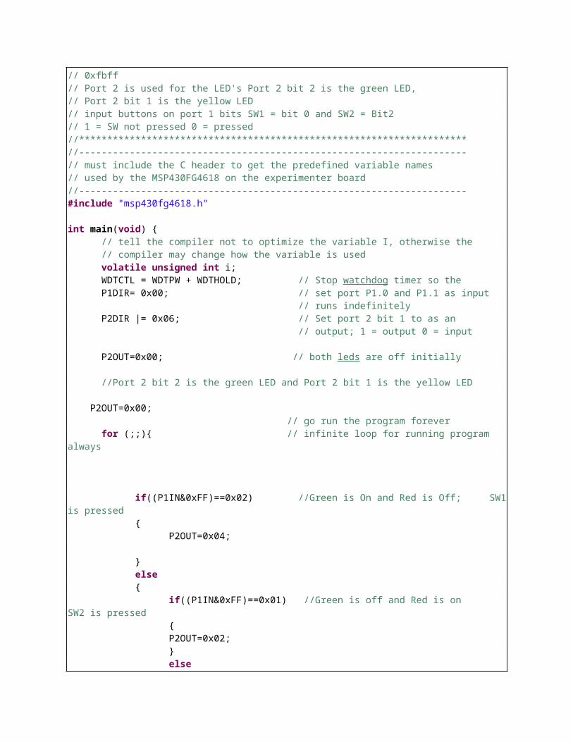
3. Write a C-language program that turns on the green LED when SW1 on the experimenter board is pressed and the yellow LED when SW2 is pressed. Execute this program and verify that it is running correctly. Make sure that this program is properly commented. Make sure to have the lab assistant verify the functionality of this program. For msp430fg4618:/*Names: Nguyen Thai Vinh Phuc Hoang Duc Nghia
Class: 10ECEGroup: Group 6*///*********************************************************************// LED turn on and off to blink the LED on Port 2 of the MSP430FG4618// experimenter board RAM at 0x1100 - 0x30ff, FLASH at 0x3100 –// 0xfbff// Port 2 is used for the LED's Port 2 bit 2 is the green LED,// Port 2 bit 1 is the yellow LED// input buttons on port 1 bits SW1 = bit 0 and SW2 = Bit2// 1 = SW not pressed 0 = pressed//*********************************************************************//---------------------------------------------------------------------// must include the C header to get the predefined variable names// used by the MSP430FG4618 on the experimenter board

//---------------------------------------------------------------------#include "msp430fg4618.h"
int main(void) {// tell the compiler not to optimize the variable I, otherwise the// compiler may change how the variable is usedvolatile unsigned int i;WDTCTL = WDTPW + WDTHOLD; // Stop watchdog timer so theP1DIR= 0x00; // set port P1.0 and P1.1 as input // runs indefinitelyP2DIR |= 0x06; // Set port 2 bit 1 to as an // output; 1 = output 0 = input
P2OUT=0x00; // both leds are off initially
//Port 2 bit 2 is the green LED and Port 2 bit 1 is the yellow LED
P2OUT=0x00; // go run the program foreverfor (;;){ // infinite loop for running program
always
if((P1IN&0xFF)==0x02) //Green is On and Red is Off; SW1 is pressed
{P2OUT=0x04;
}else{
if((P1IN&0xFF)==0x01) //Green is off and Red is on SW2 is pressed
{P2OUT=0x02;}else{ if((P1IN&0xFF)==0x00) //Green is On and Red is Off
SW1 is pressed and SW2 is pressed { P2OUT=0x06; } else { P2OUT=0x00; //Green is oFF and Red is Off
both 2 of witched are not pressed }}
} }
}
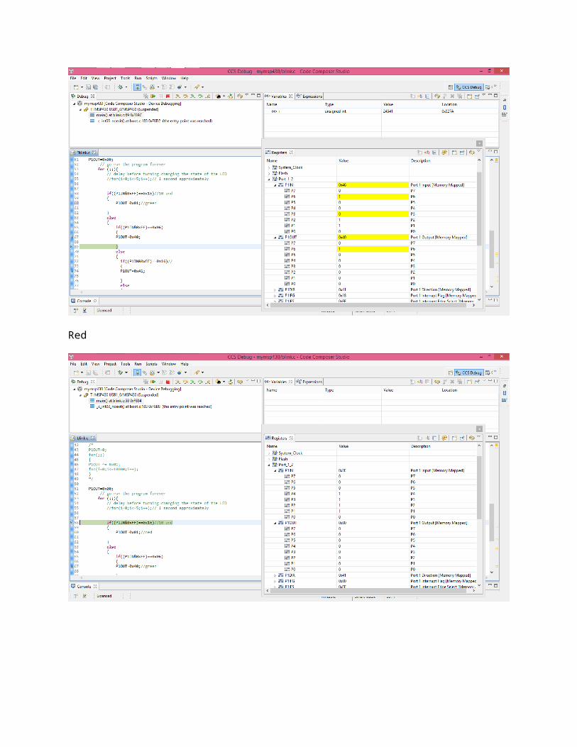
Press F5 to go step by step for seeing what happens inside registers.
Green led is on and red led is off
Red led is on and Green led is off

Both leds are off.
Both leds are on.

ON MSP430G2231\
/*
Names: Nguyen Thai Vinh Phuc Hoang Duc Nghia
Class: 10ECEGroup: Group 6*/
#include <msp430G2231.h>
int main(void) {WDTCTL = WDTPW | WDTHOLD; // Stop watchdog timerP1DIR |= 0x41; // Set P1.0 and P1.6 to
output directionvolatile unsigned int i;
P1OUT=0x00; //initial RED and Green leds are offfor (;;){ // program is online
if((P1IN&0xFF)==0x1E) // Red is on and Green is off{
P1OUT=0x01;
}else

{if((P1IN&0xFF)==0x06)// Red is off and Green is on {P1OUT=0x40;
}else{ if((P1IN&0xFF)==0x16)//// Red is on and Green is on { P1OUT=0x41;
} else { P1OUT=0x00; // Red is off and Green is off }
}}
}return 0;
}
Press F5 to go step by step for seeing what happens inside registers.
Second putton( P1.4: general purpose)

green

Red
4. Repeat step 3, but this time writes an assembly language program to turn on and off the green and yellow LED’s .For ‘msp430fg4618.h’Button 1 is pressed and Green led on and Red led is off
;;;;;;;;;;;;;;;;;;;;;;;;;;;;;;;;;;;;;;;;;;;;;;;;;;;;;;;;;;;;;;;;;;;;;Names: Nguyen Thai Vinh Phuc; Hoang Duc Nghia;;Class: 10ECE;Group: Group 6;;;;;;;;;;;;;;;;;;;;;;;;;;;;;;;;;;;;;;;;;;;;;;;;;;;;;;;;;;;;;;;;;;; .cdecls C,LIST,"msp430fg4618.h" ; cdecls tells assembler to allow ; the c header file
;------------------------------------------------------------------------------; Main Code;------------------------------------------------------------------------------

.text ; program start .global main ; define entry point
main mov.w #0x300,SP ; initialize stack pointer mov.w #WDTPW+WDTHOLD,&WDTCTL ; stop watchdog timer mov.b #0x00,&P1DIR ; set input for switch 1 and 2 bis.b #0x06,&P2DIR ; make P1.0 and P1.6 output ; all others are inputs by default mov.b #0x00,&P2OUT ; set intial both of two leds off
mainloop bit.b #0x02,&P1IN ; read switch at P1.1; active low switch of yellow led(switch 2)
jnz off1 ; 00
On mov.b #0x02,&P2OUT ; Yellow on 01 bit.b #0x01,&P1IN ; Read SW1 switch of green led(switch 1) jz on2 ; 11
jumpmain jmp mainloop ;
off1 mov.b #0x00,&P2OUT ; set P1.0 (red on) 00 hoac 0x bit.b #0x01,&P1IN ; read switch at P1.0 jnz mainloop ; 00
on2 xor.b #0x04,&P2OUT ;Green is on jmp mainloop ;
;------------------------------------------------------------------------------; Interrupt Vectors;------------------------------------------------------------------------------ .sect ".reset" ; MSP430 RESET Vector .short main ; address to start execution
.end

Status register:
Green led off and Red led is on

Green led is on and Red led is on
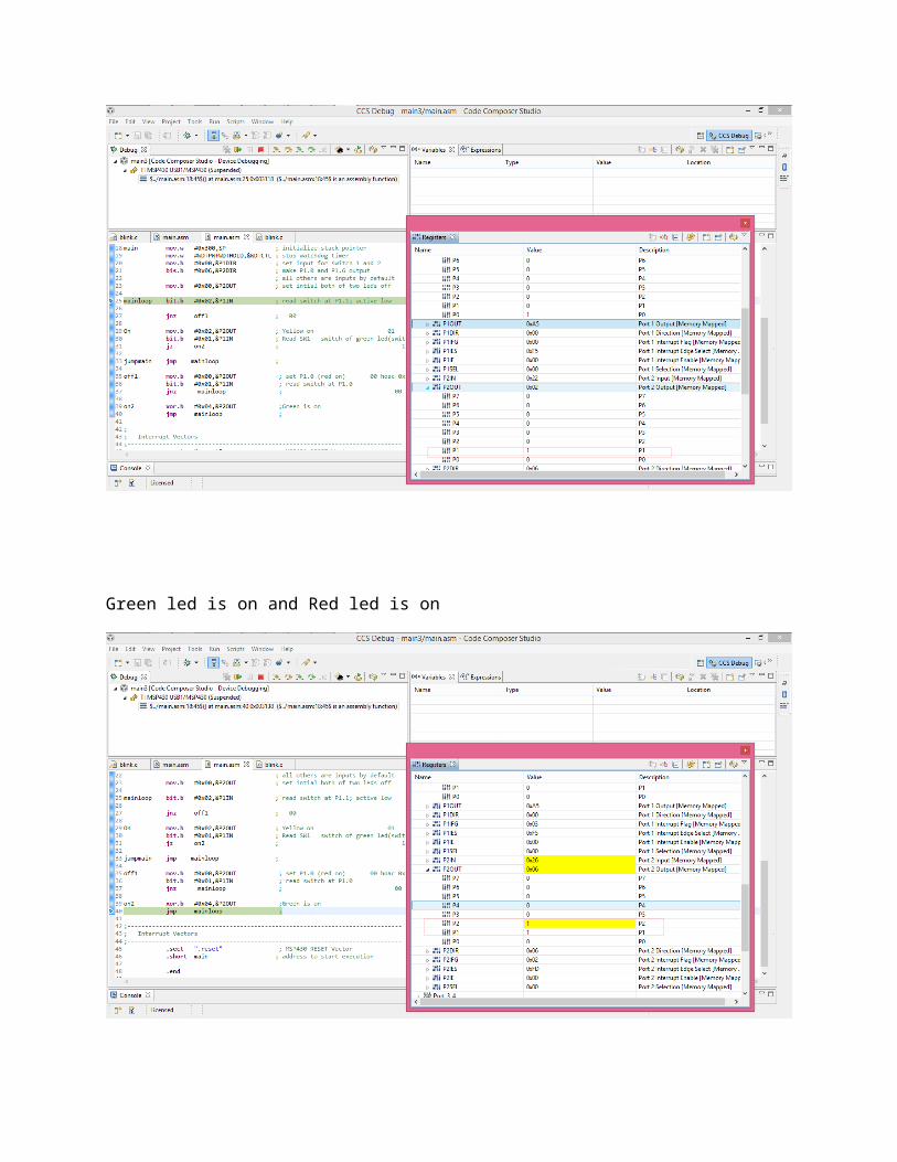
Green led is off and Red led is off