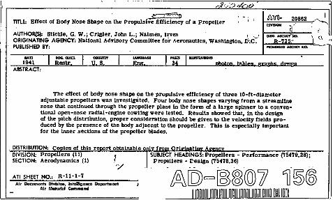
report no. 725 - defense technical information center · for propellers of a different pkm form;...
TRANSCRIPT
REPORT No. 725
EFFECT OF BODY NOSE SHAPE ON THE PROPULSIVE EFFICIENCY OF A PROPELLER
By GEOFLGEW. STICKLE, JOHN L. CEIGLER, and IEYEN NAIMAN
SUMMARY
Three adjustable propellers ofoperated in front of four body nose
10-joot diameter wereshqe8, rar@q from a
streamline nose that continued through-the pro~eller planein the form of a large gpinner to a. conventional opemnoseradial-engine cowling. One propeller hud airfoil sectimsclose to the hub, the second had conventional round Madeshanks, and the third diferedfrom the second only in pitchdistribution. The blade-angle eettings ranged from 20° to66° at the 0.76 radiu8.
The e~ect of the body nose dupe on propulsive eficiencymay be ditviied into two parts: (1) the change in the bodydrag due to the propeller slipstream and (2) the change inpropeller had distribution due to the change in ~elaitycaused by the body. For the nose $hape tested in. thisreport, the jirst e$ect i~ 8hown to be wry small; therefore,the chief empha+?l”8of the report i8 conjined to the seconde~ect.
The re8uJt88howed that, in the de~ign of the p“tch di~tri-bution, proper comideration. 8hou/d be yizen to the reloc-ity&ld produced by the presence OJthe body adjacent to th-epropeller.
The pre8ence of a body behind the propeller produce8 it8greate8t e~ect on the inner 8ections of the propeller blades.Ii-hen the inner 8ection8 are of concenti.onal round-8hank
- de8ign, the important e$ect is the change in the drag ofthe8e section8 due to the reduced reloeity in front of thebody. For inner section8 of an a.irjoil design, the maintttect is the change of the load distribti”on oj the propellerdue to increasing the angle oj attack by reduction of theforward reloeiiy. The gain in ejitienq realized bycovering the propeller hub with a 8p”nner is a functionoj the local velocity to which the hub ti expo8ed; the pos8iblegain increa8es as the pow~r loading decrea8e8.
INTRODUCTION
The tests reported in reference 1 showed that thecharacteristics of a propeIler are dependent on the bodybehind the propeller. The difference in the velocitydistribution in front of two open-nose NACA cowlingscaused a change of 5 percent in the propulsive efficiency.
A propeller that hud a constant pitch distributionwhen set 30° at the 0.75 radius was shown by the teakof reference 1 to give higher propulsive efficiencies thana similar propeller with a constant pitch distributionwhen set 12° at the 0.75 radius. Tests reported inreference 2 showed a reverse effect of pitch distribution
for propellers of a different pkm form; the propellerthat had a constant pitch distribution when set 35°at the 0.75 radius gave slightly low”erefficiencies overthe entire high-speed flight range than the one set 15°.The resuItsshown in reference 1indicated the possibility -that these apparently contradictory results of the effectof pitch distribution might be e.xplaineclby the effectof the body shape in changing the local nngle of attackof the propeller sections.
This report presents results of three full-scrde propel-lers tested in front of several nose shapes. The bodyshapes ranged from a streamline nose c..tending throughthe propeller disk with a large spinner to the normaltype of blunt-shape, open-nose cowling. The resultsindicate how the body shape affects the local pitchclistribution gnd the charts show the effects of thischange on the propulsive efficiency.
hb
;xD1“n.V/nD
PB-0UQ
P
;c.R
D
ADCDACD
AD,
ACDP
SYMBOLS
thickness of blade sections of propellerwidth of blade sections of propellerstation radius of propeIlertip radius of propellerfraction of tip radius (r/R)diameter of propellervelocity of free air strertmrevolutions per unit time of propellerticlvance-diameterratio of propellergeometric pitch of propellerpropeller blade-angle setting at 0.75Rpropeller blade anglevelocity in plane of propollcr, propelIer removedmass density of airdynamic preesure of air stream 04PV)power input to propellerpower coeilicient (P/pnW)net force on thrust baknce of propeller-nacel[e
unitdmg of nacelle for corresponding airspeed
measured with propeller removedchange in nacelle drag due to spinnerdrag coefficient (D/@)change in nacelle drag coefficient due to spin-
ner (AD/q.F)change in nacelIe drag due to propeller slip-
streamchange in nacelle drag coefficient due to pro-
peller slipstream (DP/@)
371
372 REPORT NO. 72&NATIONAL ADVISORY COMMITTEE I?OR AERONAUTICS
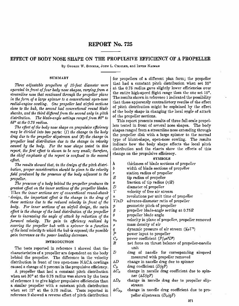
B, boffle plofe— : . .:: ~:.:. ,“..
FIOUWI I.–Line drm’lng of the test errangernente,
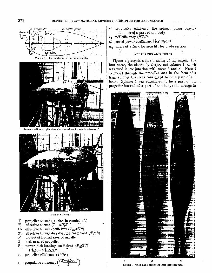
FIGURE 2.—Nine 1. (Not ehmn here was oIesed for teste In tMs report.)
T propellm thrust (tension in cranksl]~ft)2’, effective thrust (T–AD~J- -L’. effective thrust coefficient (TJ@D)T, effective thrust disk-loading coefficient (TJgS’)F projected frontal arm of nacelleS disk mea of propellerPC power disk-lortding cocfficitmt (P/gW)
1/qF.= v7ps/2P “
rlP propcher effirienc.y (TV/P)
(
(T–AD.)J~ propulsive efficiency ~
?
q’ propulsive efficiency, the spinnerqc~.a part of the body
~m ne~efiiciency (lW/P)C, _sp&xl-powercoefficient (~pTT/Pn2)
being consid-
CYaonngle.of attack for zero lift. for blwlc section:-;
APPARATUS ANDTESTS -
Figure 1 pres~nts a line drawing of tly naccllc: thefour noses, the afterbody shape, and spinner 1, whirhwas used in conjunction with noses 3 and 5. Nose 4extended through the propeller disk in the form of alarge spinner that was consid.cred to be a pmt of lhcbody. Spinner 1 was considered to bc a pnrt of thepropeller instead of a pmt. of tl~cbody; the chnnge ill
P c 0.FIaUEE 4.—One blade of eeob of the three propellers mod.
●
EFFECT OF BODY NOSE SHAPE ON THE PROPULSIVE EFFICIENCY OF A PROPELLER 373
body drag caused by spinner 1 was therefore disregardedin computing the propulsive efficiency.
The tests were conducted in the NACA 20-foot windtunnel described in reference 3. Figures 2 and 3 showthe installations of noses 1 and 4 in the tunnel. A 150-horaepower variable-speed eIectric motor enclosed inthe nacelle furnished power to the propeller.
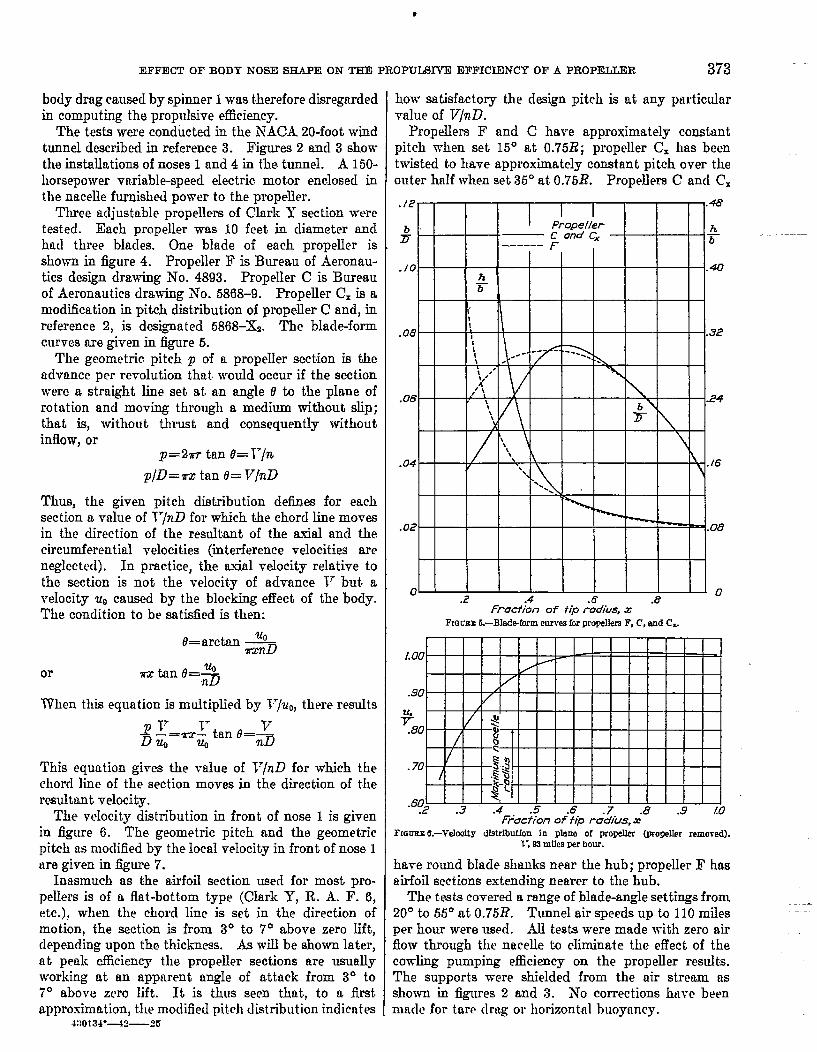
Three adjustable propellers of Clark Y section w-wetested. Each propeller was 10 feet in cliameter andhad three blades. One blade of each propelIer isshown in figure 4. Propeller F is Bureau of Aeronau-tics design drawing ATO.4893. Propeller C is Bureauof Aeronautics drawing A70.5868–9. Propeller C= is amodification in pit& distribution of propeller C and, inreference 2, is desia~ated 5868–&. The blade-formcurves are given in figure 5.
The geometric. pitch p of a propeIIer section is theadvance per revolution that would occur if the sectionwere a straight line set at a-n angle o to the plane ofrotation and moving through a medium without slip;that is, without thust and consequently withoutinflow, or
p=2n-r tan O=Jr/n
p/D=ux tan 6= V/nD
Thus, the given pitch distribution defies for eachsection a value of V/nD for wtich the chord line movesin the direction of the resultant of the axial and thecircumferential velocities (interference velocities areneglected). In practice, the axial velocity relative tothe section is not the velocity of advance V but avelocity U. caused by the blocking effect of the body.The condition to be satisfied is then:
t?=arc.tan -J&
or
When this equation is multiplied by V/uO,there results
~~ ‘DUQ
=u+ tan e=n$
This equation gives the value of V/nD for which thechord line of the section moves in the direction of theresultant velocity.
The velocity distribution in front of nose 1 is givenin figure 6. The geometric pitch and the geometricpitch as moclified by the locaI velocity in front of nose 1tiregiven in figure 7.
Inasmuch as the airfoil section uaecl for most pro-pellers is of a flat-bottom type (Clark Y, R. A. F. 6,etc.),when the chord line is set in the direction ofmotion, the section is from 30 to 7° above zero Iift,clepending upon the thickness. As will be shown later,at peak cflicienc.y the propeller sections are usuallyworking at an apparent angle of attack from 3° to7° above zero lift. lt is thus seen that, to a firstapproximation, the modified pit,ehdistribution indicntes
4:10134”+2—25
how satisfactory the dwiign pitch is at any particularvalue of V/nD.
Propelle~ F and C have approximately constantpitch when set 15° at 0.75R; propeller C!x has beentwisted to have approximately constant pitch over theouter hdf when set 35° at.0.75R. Propellers C ancl CX
““~””+t--H-??+t-l-+
/! i,\ h. h.IIR
o~ [ I I 1 I t I I I [.2 .4 .6 ./?
o
fraction of tiprffdius,x ‘-FKWBE 5.—B1adrAorm curwa for propellers F, C, and CL.
+.80
.70
.602 .3 .4 .5 .6 .8 .9fractionof iipra”$ius,x
LO
FIGURE 6.–Velooity distribution in plsne” of proti (propeller removal).
1“, 93 mfks per hour.
ha-re round bIacIeshanks near the hub; propelIer F hasairfoiI sections extending nearer to the hub.
The tests covered a range of blade-angle settings from20° to 55° at 0.75.R. Tunnel air speeds up to 110 milesper hour were used. All tests were made with zero airflow through the nacelle to eliminate the effect of thecoding pumping efficiency on the propeller results.The supports were shielded from the air stream asshown in figures 2 and 3. hTo corrections have beenmaclc for tare drag or horizontal buoyrmcy.
—--.

●
374 REPORT K(J . 725--NATIONAL ADVISORY COMMITTEE FOR AERONAUTICS :
RESULTS
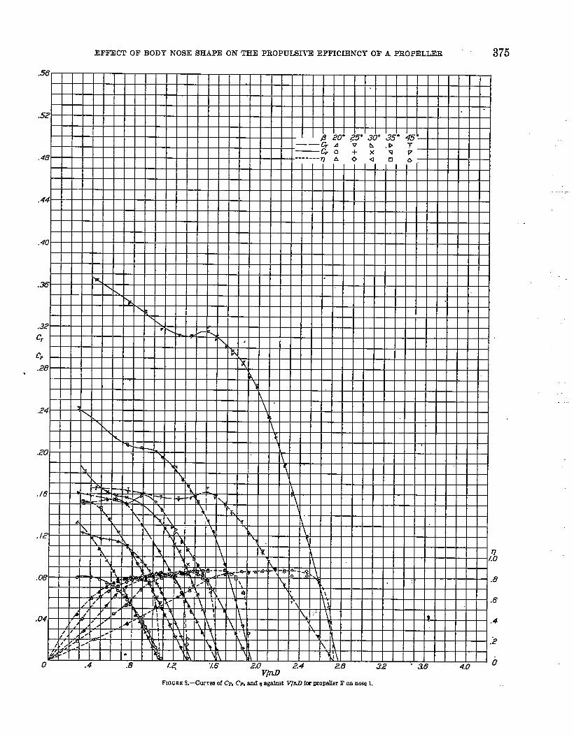
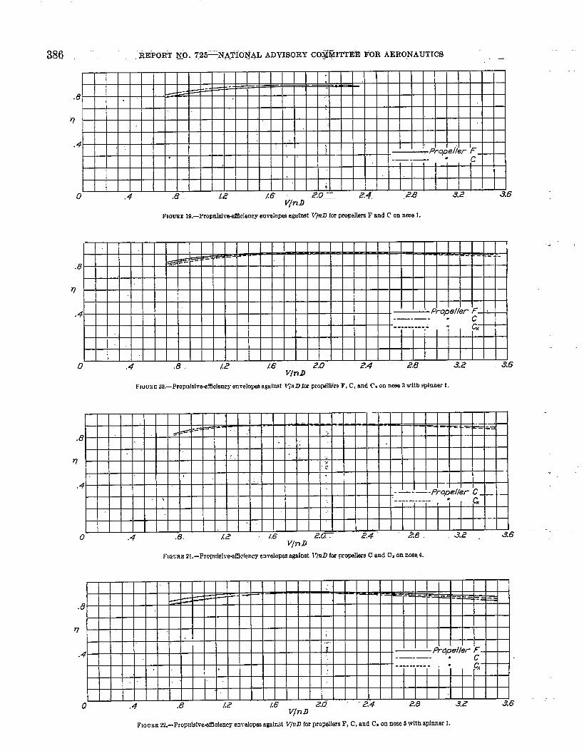
The original test points are given in figures 8 to 18,where the usual thrust coefficient C~, power coefficientCF, and propulsive ef5ciency q are plotted againstV/nZl. Each figure gives the complete range of blade-a.ngle settings for one propeller tested in conjunctionwith one nose. Figure 19shows the propulsive-efficiencyenvelopes against V/nD for nose 1 with propellersF “and C. Figure 20 shows similar results for nose 3and spinner 1 with all three propellers; figure 21 showsresults for nose 4 with propellers C and Cx; and figure22, for nose 5 and spinner 1 -with till thr~e propellem.
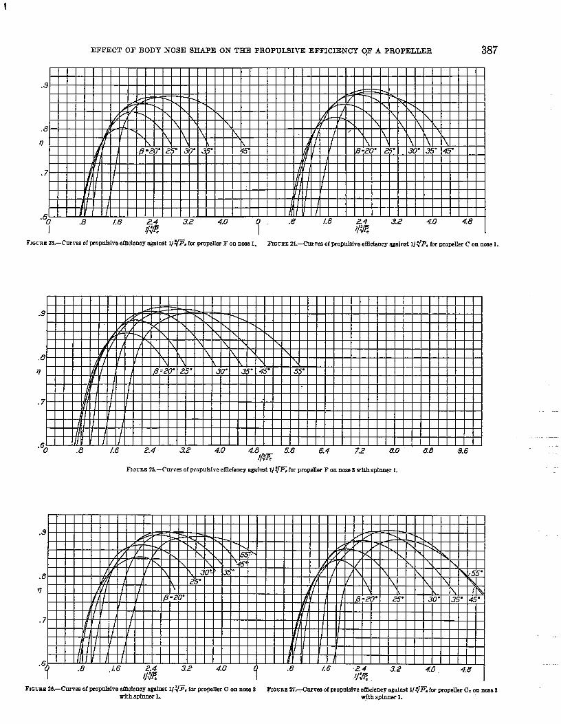
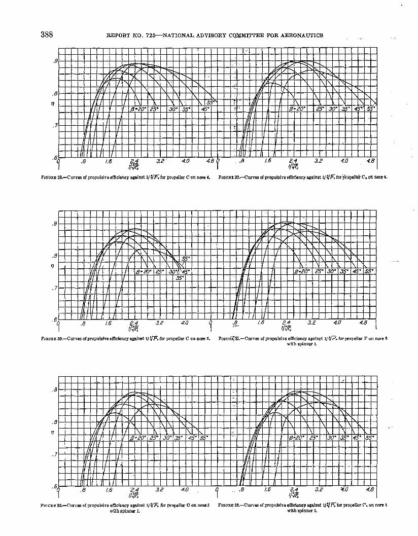
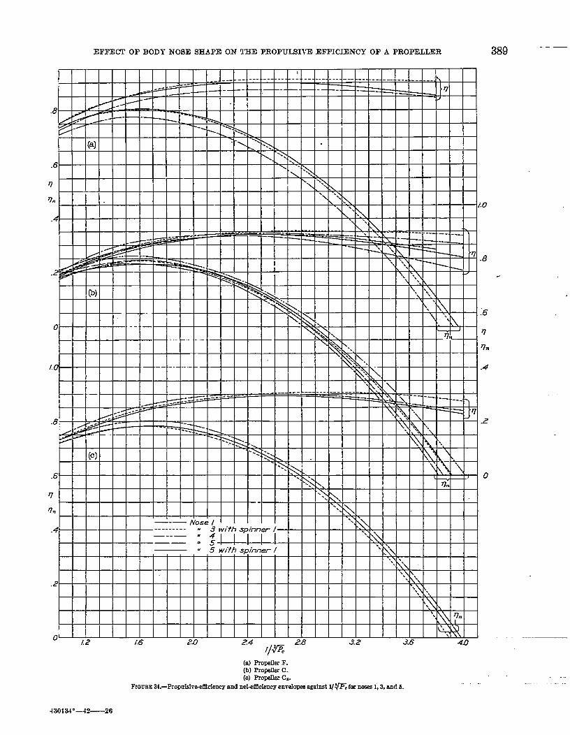
In figures 23 to 33, ~ has been plotted against l/~,for each propeller tested in conjunction with each nose.Figure 34 is a comparison of the propulsive-ei%ciencyand the net-efficiency envelopes against l/$~C for noses1, 3, and 5 with all three propellers.
The drag results from tests without the propeller forall the noses are given in the folIowing table:
\ 1 t P: i- . .
:8$.! o:~-- .,;$ 29:2 . B7?3 With spinner 1.4 .2?3.8 . Oilo
!n.6 .I17m: 28.1 .0744 With spfnnsr 1.
1 I I 1 .>-” 1.
This table shows that the addition of spinner 1 de-cremed the total drag of nose 3 by 1.1 pounds but thutthe spinner increased the total” drag of nose .5 by 0.6pound. The change in the propulsive efficiency re-sulting from the addition of the spinner mity bc writtenas a function of the change in drag coefficient of thebody, of P.j and of the dimensions of the set-up:
AC~ F ““.—
——7’”=7+ P, s
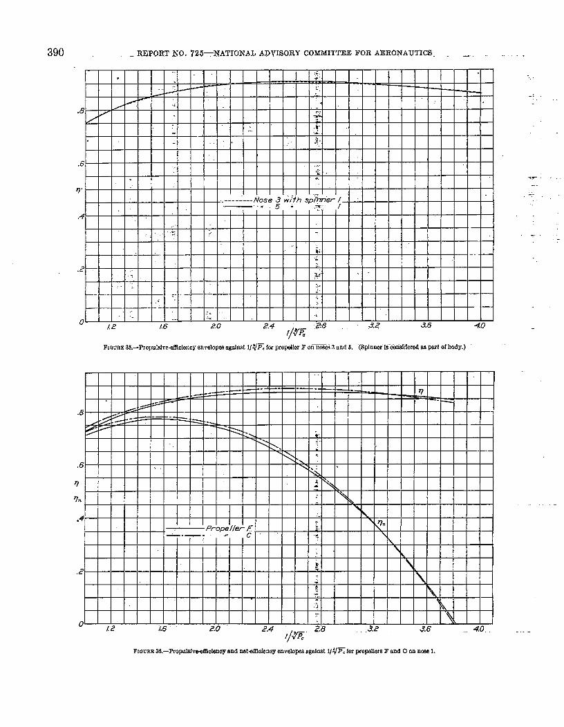
where # is the propulsive efficiency computed when thespinner is considered as part of the body. The Kighpropulsive efficiency of nose 3 shown in figure 34 is theresult of considering the spinner as part of the propoller.When the propulsive efficiency in figure 34 (a) is re-computed by considering the spinner as pnrt of thobocly (i. e., by using the drag of the body with spinner),it is seen that the envelopes for noses 3 and 5 almost .
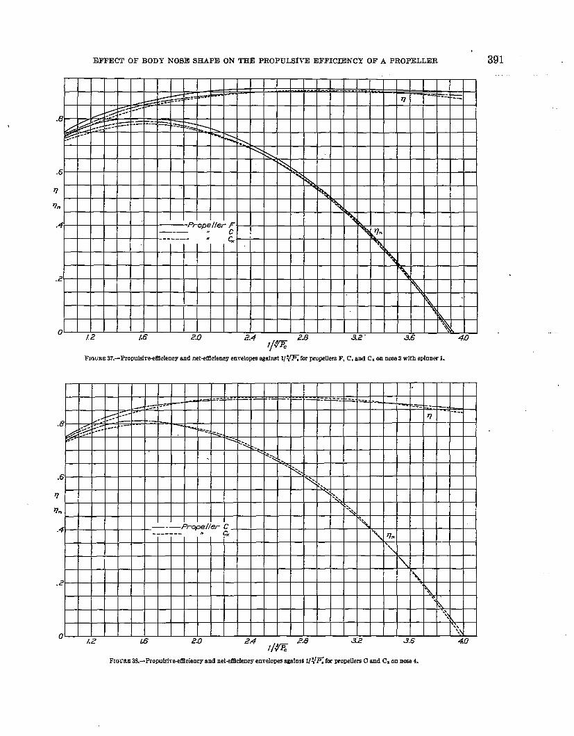
coincide (fig. 35).‘1%: net-efficiency rmd the propulsive-efficiency en-
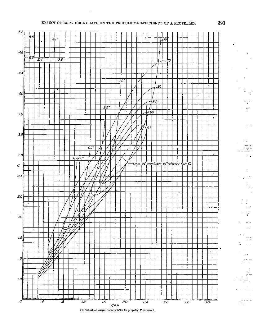
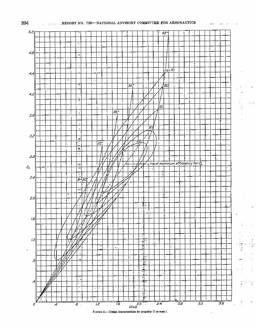
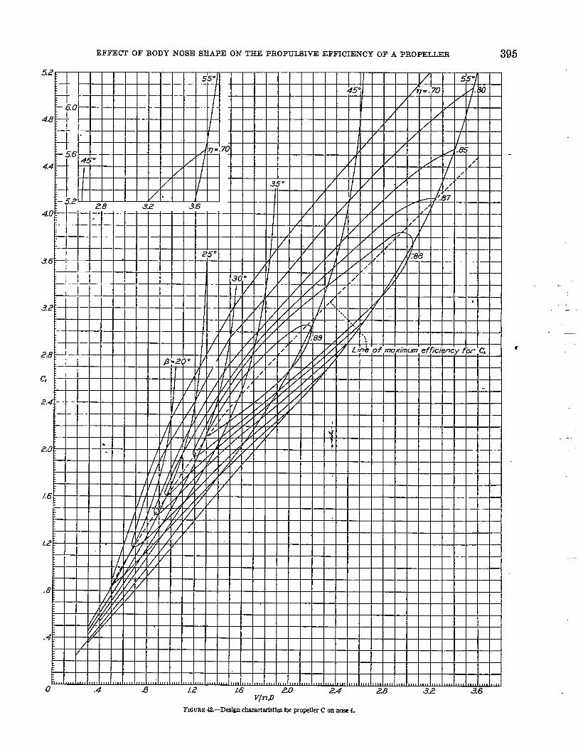
velop~~are plotted against l/\lEin figures 30 to.3~.Figyres 40 to 43 are design charts inchided as an nid
in determining the propeller cliameter for-”conditiom ofhigh-.ecd flight. “The use of this type of C, curvo forclesigg characteristics is explained in the appendix ofreference 1.
(8) Propaller F. (b) Prope.tier C: (c) PropslIsr C=. . . .
FIGUEE 7.—PkIr distributions.
EFFECT OF BODY NOSE SHAPE ON THE PROPUISIIT! EFFICIENCY OF A PROPELLER 375
FIGGRE S.—Curves of CT, CP, and q againstV/nD la Kopder F m nose 1.
376 REPORT. NO. 725--NATIONAL ADVISORY CUM>fIITEE FOR AERONAUTICS
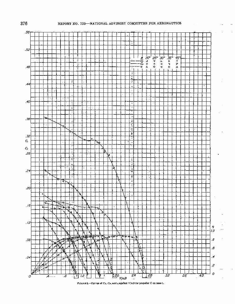
FIGURE 9.—Curw C4 c% G, and q agafast V/nD fur mwller C on n~ 1.
EFFECT OF BODY NOSE SHAPE ON THE PROPULSI1’E EFFICIENCY OF A PROPELLER 377
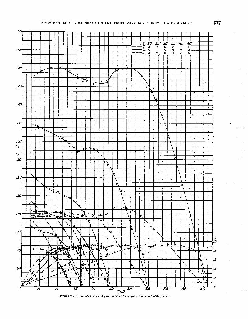
V/nDFIGI,UWI 10.—Curves of C%, Cp, &nd q agslnst Vj%D for propeller F on nose 3 with spinner 1.
378 REPORT h-O . 726—NATIONAL ADVISORY COMMITTEE FOR AERONAwrlCs ..
J.8.6
.4
.2
0V/nD
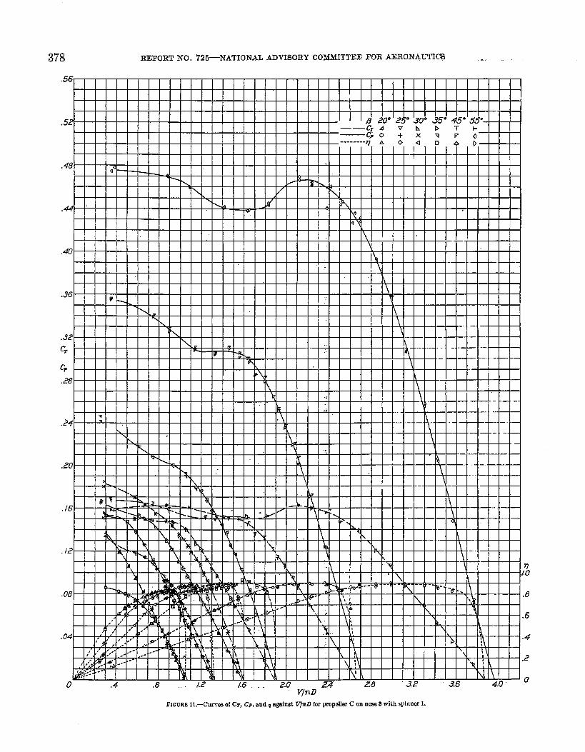
FIGURE I L-CW* 0( CT, Cp, and ~ against W71Dfor propdlor C on now 3 with sPInnw 1.
EFFECT OF BODY NOSE SHAPE ON ‘IHE PROPULSIVE EFFICIENCY OF A PROPELLER 379
.48
.44
.40
.-
Cr 1 I I I I [ I I I I I I I I I I I I II I II
.24\ 1 1 I 1 I 1 1 1 1 1 1 I I Ll I 1
\ . I\l I 1 I I I I h I
-- \.<U
.16
, /2
v.-,Ww, , I , , , I I , 1 1 \ 1 1 b # 1 1 I
\ Ill 141’ I ‘it I T\ . ‘L I IT I Iw
. .
T.-, , I ,
-.-. \l I
I ‘L17 -.lob..8
1 I I I I I I ‘d I I I “~. tll 1.I I I I k I I I
I }~ ltll\t .6
I 1 t I 1 1 I ‘. \l
?.4
.2
00
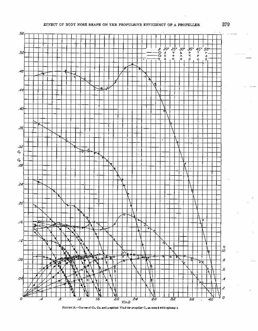
V/nDFIGCEE 12.-Currex of cl., CP, and q agsfnst V/nD forpropeller C. m nme 3 with spfnner 1.
-.
380 mwo~r NCI..725—NATIONAL ~wsolw COqIT’rEE FOR AERONAUTICS
.56—
.52
.48
.44
1
I I Ill I I II I I I I I I
.40
.36
.32
G
Cp.28
.24
.20 —..
k-t ‘- ‘- – --”;-
./6I
./2
,08
.04
0 Jqh.D
.6
.4
.2
0
..
—
---
EFFECT OF BODY hrOSE SHAPE ON THE PROPIJMIT~ EFFICIENCY OF A PROPELLER 38.I
/.%
.8
.6
.4
.2
0q’izo ,
FIGURE 14.—Curws of G, CP,and q agalmt VW for LXKIMer CX on nme i.
382 REPORT NO. 725—-NATIONAL ADVISORY CQ–MMITTEE FOR AERONAUTICS
.56
.52
.48
.44
.40
.36
., — -. .—.- .- A. .- . . . .
1
\,
t h
.32
Cr
Cp
.28
.24
.20
.16
./2
.08
6’4
‘i
FIGURE 15.—CWW of CT, CP, and q agdnst T~nD for propeller C on now b.
v.0
,8
,6
,4
.2
0
.!
EFFECT OF BODY NOSE SHAPE ON THE PROPULSIVE EFFICIENCY OF A PROPELLER 383
.12
n1.0
.m .8
.6
—.
.04 ‘-; ‘,’ ,--- ~~ “ , v . M\ 11 T
\ ~ \ \ .4. ,’ ,, ,. . A. \
,, %+’ . . ---,’ . .’ , .- --- NJ : J ;, \
1%.2:
,1% I
~t ;A
0 .4 .8 1.2 L6 24 28 0v~i%
.32 36 40
FmriKE 16.—Curws of CT, C’F,snd q agatnst T’/nD [W propelkr F on now 5 with spfnnar 1.

,
384 REmRT NO. 72*NATIONAL ADVISORY tM*ITTEE FOR AERONAUTICS—
V@ ‘“
.8
.6.
.4
.2
FIGURE 17+311w5 of C%,G, and T figa[nst V/nD for propelkr C on mm 6 with splnnar 1.
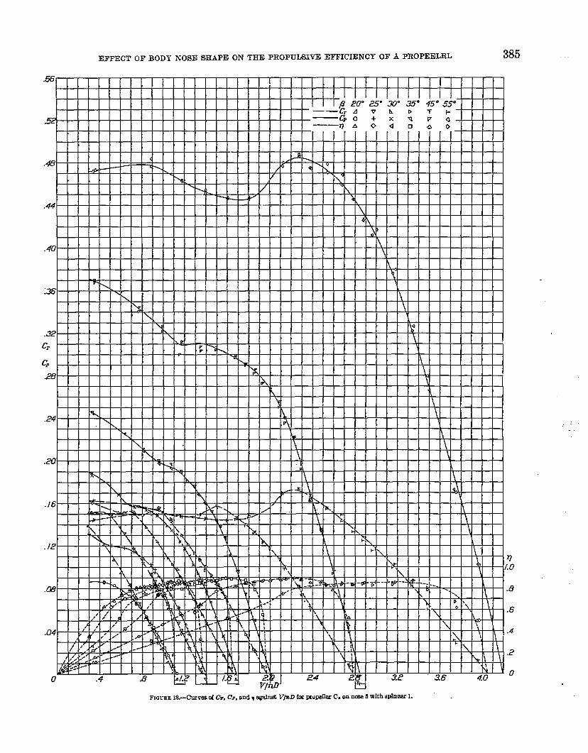
EFFECT OF BODY NOSE SHAPE ON THE PROPULSIVE EFFICIENCY OF A PROPEELRL 385
c,
c=.26
.24
/9
7
a
.16
.,A.
?1.0
.Gk3 .8
.6
.04 .4
.. .
386 BEFORT No. 72E+NA.TIOIQAL ADVISORY COM~ITTEE FOR AERONAUTICS
.8
v
.4
0 6
FIGuRE 19.—Propoleive-ef.tlciency enrelop- against V/nn for PmPelle= F and C on nme 1.
.8
v
.4
0 6Vjn D
..
FIUU m w.—prop~]lsi~,=rndency envelopes against Vln D for pmr@M F. C t and C, on nme 3 ~th winner 1.
.8
v
.4
06 .:. .
V/nD
FIGURE 21. —Propulef w-efllclency enveiopea against T’/nD for propellwe C and C. on nose. 4.
.8
v
.4
0
FIG L!EE 22.-Propulsive&llotency enveiopea against V/nn formwellersF,c,andC. on nose6with SPInuer1.
EFFECT OF BODY NOSE SHAPE ON TEE PROPULSIVE EFFICIENCY QF A PROPELLER 387
.9
.8
r?
FHXRE Z3,-Crmws of fxnpdsive Mfciency agairrsl I/~~. for propeller F on ncw L FIGCEE 24.–~rc5 Of BOpUfSfW ernCk2KICYEjg@fi l/w. f~ I)rOP.2&r C On n~ 1.
.9
.8
L’
.7
.60 .8 /.6 2.4 .32 4.0 4.8 56 64 7.2 8.0 8.81/’
9.6
FIWXE ‘25.-C’urrm of propukfre efticfency against 1/:= for propeller F on nme ~ with spinner 1.
FIGtXKi M.-Curves of propnfsive efficiency agsimt I/~~, for propeffer O on nrse 3 FIOCRE Z7.-Curws O( propnkfve eftidency against l/~~. for propdkr C, on now S
w(t h SpfJ.KW 1. wjth Sphlllw 1.
388 REPOR’1’ NO. 72&NATIONAL ADVISORY CQMMI1”I’EE FOR AERONAUTICS —
FIOUEE Z&–Curves of propuhke efUcleney ogafnst l/~~. ~or pmpaller C on nrm 4. FJourm 20.-Cnrvfa ofpropulsivee$flc!eneyagainst l/#.% fcf-fiiopelliiC, on nose4.
FIOURE 30. —CurvC% of propuMve ef6cIency against l/~. for propelkx C on nose & FIGL!R”EY,-Corves of propulsive eIliclency agahut 1/ ?~. for Ijmpellor F Cm nose 1!
with spinner 1.
FIOURE 32.—CWW of propuk?lre eftfcbw e.gdnet l/~~. for profdk C on mm 5 FIGUEE 38.—CUIWS of propu]s[ve efEdency age.tnet 1/~PTfo; propsller (’, on nm 3
with s[)hmx L with sIJ[nner 1,
EFFECT OF BODY NOSE SHAPE ON THE PROPULSIllE EFFICIENCY OF A PROPELLER 389 - ‘-—
I I I I I I I I I I I I I t 1 I I I $t I i I I I I I I I I I I I
.8
.6
.4
.8 z
.6 0
v
G’*
.4
.2
0/2 /.6 20 2.4 2.8 3.2 3.6 447
I/n
—.
(a) ProIMIer F.
(b) Propeller C.
(c) PropeIler Cx.
FUXJEE 34.—PropuIsIwef33ciency and net-e5cierrcy envdo~ against l/~~, for noses 1,3, and 5.—.
43$) 1344-’42-20
390 .- REPORT K(3. 725-NATIONAL ADVISORY COMM~l~EE FoR AERo~AU~IW – -.
.8
.6
7’
.4
.2
0/.2 f.6 2.0 2.4 .3. 3.2 3.6 40
Iplz
I
FKWRE [email protected] envelop~ agalmt l/~~~, for procder F on=c~ 3 and 6, (6plnner k. tiiekiemd es pert of body.)
.8 1 I I I.- - -I
I
.6
v
%
.4
.2
0/2 f.s 20 2,4 28 3.2 3.6 4.0
I/n
—..
---
FIGURE 36.-PropuIefwAfloIenoy and net#Mency envelopee againet l/$./~ for propellers F and C on noee 1.
EFFECT OF BODY NOSE SHAPE ON THE PROPULSIVE EFFICIENCY OF A PROPELLER 391
.,?I 1
I I I I I1 1 I ( I 1 I I \\l 1 I 1
012 L6 2.0
I/m
I2.4 ..— 2-6 3.2 “ 36 4D
FIGURE 37.-PropuIaI%efficIency and net-etlktency envelo~ agdmt l/~m for pmpeUera F, C, and C, on nom 3 w[th sp[nner L
.8
.6
v
%
.4
.2
01.2 L6 2.0 2.4 2.8 u 3.6 40
I/ire
FIGURE 3&-Propulske+fEmencg and ne4-emekncy envelopes against I/?= fm propelIeca C! and C, on m 4.
392 REPORT NO. 72&NATIONAL ADVISORY COMMITTEE FOR AERONAUTICS
DISCUSSION
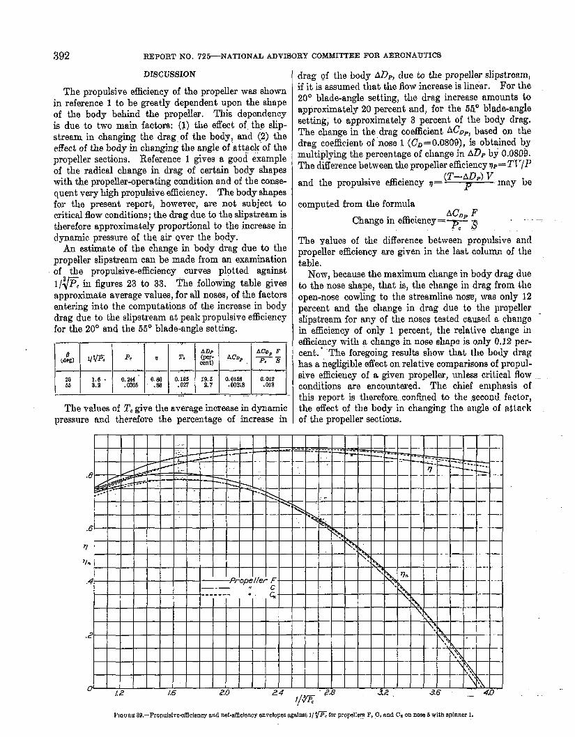
The propulsive efficiency of the propeller was shownin reference 1 to be greatly dependent upon the shapeof the body behind the propeller. This dependencyia due to two main factors: (I) the effect of. the slip-stream in changing the drag of the body, and (2) theeffect of the body in changing the angle of ~t~ck”of thepropeller sections. Reference 1 gives a good exampleof the radical change in drag of certain body shapeswith the propeller-operating condition and of the conse-quent very high propulsive efficiency. The body shapesfor the present report, however, are not subject tocritical flow conditions; the drag due ta the slipstreamistherefore approximately proportional to the increase indynamic pressure of the air Qver the body.
An estimate of the change in body drag due to thepropeller slipstream can be made from an examinationof the propulsive-efficiency curves plotted against1/~ in figures 23 to 33. The following table gives
approximate average value3, for all noses, of the factorsenteri~g into the computations of the increase in bodyclrag due to the slipstream at peak propulsive efficiencyfor the 20° and the 55° blade-angle setting.
I 1 I 1 1 -’[ I [ !
v== =qT=tjy_‘O::;(“... ,.=The values of T, give the average increase in dynamic
pressure and therefore the percentage of increase in
drag of the body ADF, due to the propeller slipstream,if it is assumed that the flow increase is linear. For the20° blade-angle setting, the dmg increase amounts toapproximately 20 percent ancl, for the 5fi0 blade-anglesetting,to approximately 3 percent of the body chg.
The change in the drag coefficient ACDP, based on thedrag coefficient of nose 1 (CD= 0,0809), is obtained bymultiplying the percentage of change in ADIJby 0.0809.The clifferencebetween the propeller efficiency= T~’/~’
and the propulsive efficiency v=(T–A~p) T7~:”’n”y be
computed from the formulaACDPF
Change in efic.iency=~ ~ ~ -
The ~alues of the difference between propulsive andpropeller efficiency are given in the last column of thetable.
Now, because the maximum change in body drag dueto the nose shape, that is, the change in drag from theopen-nose cowling to the strea.mlinenose, was only 12percent and the chmge in clrag due to the propellerslipstream for any of the noses tested caused a changoin efficiency of only 1 percent, the relative change ineffici~cy with a change in nose shape is only 0.12 per-cent. “’ “The foregoing results show that the body draghas a negligible eflect on relative comparisons of propul-sive efficiency of a given propeller, unless critical flow ._conditions are encountered. The chief emphasis ofthis report is therefore. confined to the second factor,the effect of the body in changing the angle of nttackof the propeller sections.
Na urtu 39.–PropnMv&efRcIency and net-efdclency envelopw agahet 1/’~ for prowll~ F, C, and CL on new 5 with sphncf 1.
EFFECT OF BODY NOSE SHAPE ON THE PROPULSIVE EFFICIENCY OF A PROPELLER 393
.
V/nD
FIGCRE 40.-Desi@ characteristics for propdkr F on nose 1.
●
,..
,.. ——
.—..
.-
,.. .
.-. . .
. ...-
.
___
——
394 . . . . REPORT NO. 726-- NATIONAL ADVISORY COMMITTEE. FOR AER.CINAUTICS -----
c.
2.
2.
/.
1.
WnDFIGURE 41.—Ddgn characteristics for propeller C on mm L
—.
:... .-
“.7:
EFFECT OF BODY NOSH SHAPE ON THE PROPULSIVE EFFICIENCY OF A PROPELLER 395
5/?
48
44
4.0
3.6
32
2.8
c,
ILine“ofm6ximm” effici&n&yfw C.~,/A ,“ , , I , I ! L
I I , , , 1 1 1 1 $ 1
I I [
.4
0V/nD
...
t
.:
FIGUEE 42.—DHIgn eharacterfstks fm propeUer C on nose 4.
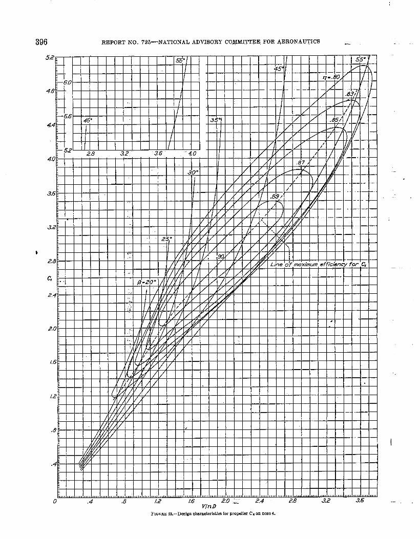
396 REPORT NO. 7%-NATIONAL ADVISORY COl&dlmEE FOR AERONAUTICS ....
o .4 .8 /.2 16 2.0 1.- 2.4 2.8 a2 3.6V/nD
.—
—
I
-..

EFFECT OF BODY NOSE SHAPE ON THE PROPULSIVE EFFICIENCY OF A PROPELLER 397
If the interference -velocities are neglected, the ap-parent angles of attack of the sections at any givenvalue of T“/n~ may be computed from the pitch-distribution curves and the velocity distribution iu theplane of tbe propeller with the propeller removed.Because of the difference in the aerodynamic charac-teristics of each section, it is desirable to refer the angleof attack to the zero-lift line. The angIes of zero liftCY=Ofor the sections of the three propelIem are given in
Frac~;n Of5tIprB-us, zo ./ .2 .3 .7 .89”
+2$@
QQ-&-4
Q
+$jj -6
+L~ .8
FIGURE 44.—Angie of zero lift.
figure 44. By the use of this figure, the apparent.angles of attack above zero lift of the sections of pro-pellers F, C, ancl C= in front of noses 1, 4, and 5 withspinner 1 are given in figure 45 at l’/n~ for m&nmmefficiency. The velocity distribution in front of noses 4and 5 was assumed to be uniform and equal to the free-stream velocity. The curves show the effect of the veloc-ity clistribution on the angles of attack of the propellersections when the propeller w-as operating at peak effici-ency. It shoulcl be noted that the low--velocity reggonin front of nose 1 causes a much higher angle of mttack.
Before the discussion of the experimental results isgiven, it is desirable to summarize briefly the conclu-
sions of propeller theory in regard to load distribution,as set forth by Gla,uert in reference 4. The observedresults are then quite readily explained.
Optimum load distribution,-The simple momentumtheory indicates that, for ma-timurn efficiency, thea.sial-velocity dist.ribution shall be independent ofradius, that is, shall be of consttint value across thewake. The general momentum theory, however, showsthat this condition cannot be satisfied owing to the highangular -velocitiesrequired near the axis. The requiredcondition by the general momentum theory for theasial-velocity incrertseis that it shall be zero at the hub,increasing rapidly with radius for a short distance toan almost constant vtilue for the remaining distance.The angular velocity has a maximum value at the huband decreases outww-d. When the analysis is furthermodified to consider the effect of the iinite number ofblades, the velocities for the inner sections are onlyslightly modified but the a.sial and the rotational inter-ference velocities rapidly decrease to zero in the neigh-borhood of the tip. When the mmlyeisis again modifiedto bclude the effect of friction, the torque, and therebythe rotational velocities, is found to be increased for agiven thrust.
Effeot of shank seotion of propeller.-The effect ofthe shank section of w propeller may be considered intwo parts: the blade sections and the pitch distribut-ion. Propellers F and C have almost identical con-struction except for the section of the shank. PropellerF has airfoil sections extending much closer to the hubthan propeller C, -which,with round sections, is designedprimarily for strength. The effect of this constructionmay be summarized as follows. At a -ralue of l/~E
%ocfion af fipradius,x(W Propeller F. (b) Propeller C. (c) Propeller C=.
FIGUXE 45.—Apparent angles of attack abo~e zero lift of aectfons at V/aD for maxlrnum ellicierrcy.
-,
.398 fiFORT NO. 725--NATION& ADV~ORY CO~MIITEE FOR DRONAUTICS
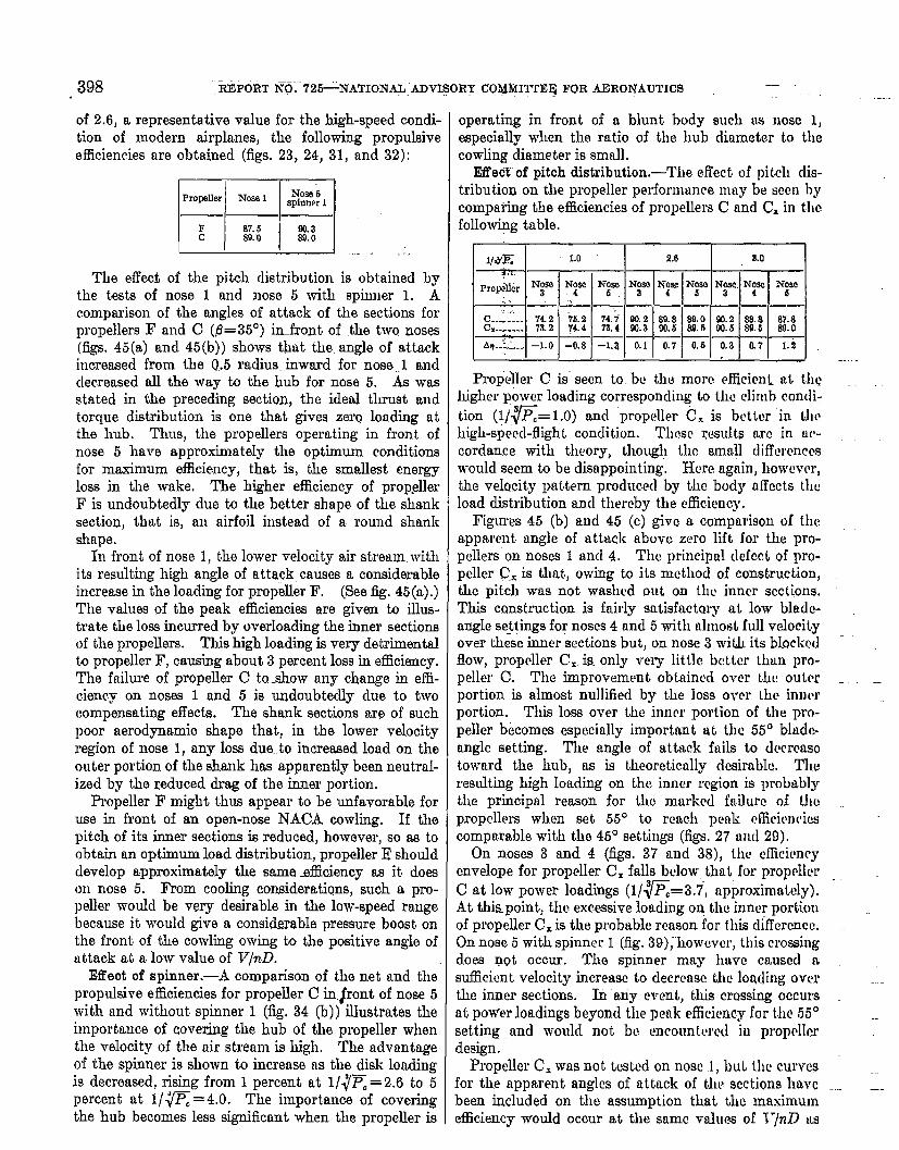
of 2.6, a representative value for the high-speed condi-tion of modern airplanes, the following propulsiveefficiencies me obtained (figs. 23, 24, 31, and 32):
-,
.
The effeci of the pitch distribution is obtained bythe tests of nose 1 and nose 5 with spinner 1. Acomparison of the angles of attack of the sections forpropellers F and C (6= 35°) imfront of the two noses(figs. 45(a) and 45(b)) shows @tit the. angle of attackincreased from the 0.5 radius. inward for nose .1 anddecreased all the way h the hub for nose 5. & wasstated in the preceding section, the ideal thrust andtorque distribution is one that gives zero loading atthe hub. Thus, the propellers operating in front ofnose 5 have approximately the optimum conditionsfor maximum efficiency, that is, the smallest energyloss in the wake, The higher efficiency of propellerF is undoubtdy due to the better shape of the shanksection, that is, an airfoil instead of a round shankshape.
In front of nose 1, the lower velocity air stream withits resulting high angle of attack causes a considerableincrease in the loading for propeller F, (See ~. 45(a).)The values of the peak e5cienciea are given to iUus-trate the loss incurred by overloading the inner sectionsof the propellers. This high loading is very detrimentalto propeller F, causing about 3 percent loss in efficiency.The failure of propeller C to show any c~ange in effi-ciency on noses 1 and 5 is umloubteclly due to twocompensating effects. The shank sections are of suchpoor aerodynamic shape that, in the lower velocityregion of nose 1, any low due..to increased load on theouter portion of the shank has apparently been neutral-ized by the reduced drag of the inner portion.
Propeller F might thus appear to be unfavorable foruse in front of an open-nose NACA cowling. If thepitch of its inner sections is reduced, however, so as toobtain an optimum load distribution, propeller I? shoulddevelop approximat.dy the sanmMmiency as it doeson nose 5. From cooling considerations, such a pro-peller would be very desirable in the low-speed rangebecause it would give a considerable pressure boost onthe front of the cowling owing to the positive angle oftittack at a low value of V/nil.
Effect of spinner .—A comparison of the net and thepropulsive efficiencies for propeller C in.#ont of nose 5with and without spinner 1 (iig. 34 (b)) illustrates theimportance of covering the hub of the propeller whenthe velocity of the tiir stream is high. The advantageof the spinner is shown to increase tMthe disk loadingis decreased, rising from 1 percent at l/~~C = 2.6 to 5percent at l/~~ =4.0. The importance of coveringthe hub becomes less significant when the propeller is
operating in front of a blunt body such as nose 1,especially when the ratio of the hub diameter to thecowling diameter is small.
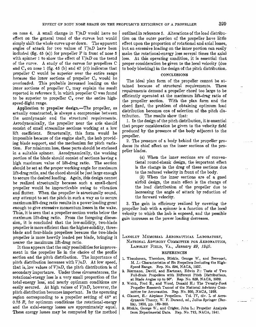
Effect of pitch distribution.-The effect of pitch dis-tribution on the propeller performance may be seen bycompatig the efficiencies of propellers C and C= in tlwfollow@g table.
~-1-,if, ; ~~ ~k ~
Propeller C is seen to. bc the more efficicmLat tllQhigher power loading corresponding to the climb cond i-tion (1/~= 1.0) and “propeller C, is better in l.hehigh-speed-flight. condition. These results nrc in tir-cordance with theory, though the smnll diflerenccswould seem to be disappointing. Here again, howevwtthe vehcity pnttern produced by the body affects theload distribution and thereby the efficiency.
Figures 45 (b) and 45 (c) give a comparison of theapparent angle of atttick abcve zero lift for the pro-pellers”on noses 1 ancl 4. The principal defect of pro-peller C= is that,, owing to its nwthod of construction,the pitch was not washed out on thu inner sections.This construction is fairly satisfactory at low Mm.lc-angle se~tingsfor noses 4 m-id5 with almost full veIocityover these inner sections but, on nose 3 with its bloclwdflow, propeller C, is. only very little better thtm pro-peller C. The improvement obttiincd over the outm - __portion is almost nullified by the loss over Lhc’inn[wportion, This loss over the inner portion of the pro-peller becomes especially importrmt at the 55° bltidc-nnglo setting. The angle of at.tac.kfails to dccrcasotoward the hub, as is theoretically dcsiralk Theresulting high loading on the inner region is pro?wblythe principal reason for the marked failure of thepropellers when set 55°. to reach pmk efficienciescomparable with the 45° settings (figs. 27 atd 29).
On noses 3 and 4 (figs. 37 and 38), the e~cicncycnveloye for propelIer CX falls below that for propollrrC at low power loadings (1/~=3.7, approximrdcly).At this point, the excessive loading on the iuncr portiouof propeller C= is the probable reason for this difference.On nose 5 with spinner 1 (fig. 39), however, this crossingdoes g~t occur. The spinner may huvc causccl nsufficient velocity increase to clecrcasc tlw loading overthe inner sections. In auy event., this crossing occursat pow’erloadings beyond the pmk efficiency for the 55° --setting and WOUMnot bo encount.wed in propcllerdesign.
Propeller CXwas not tested on nose 1, hL tll~ curvesfor the apparent angles of uttack of the.sections huvc ~.been i.ucluded on the assumption that the maximumeficiemcy would occur at the same values of 1“/nZl us
EFFECT OF BODY NOSE SHAPE ON THE PROPULSIVE Efficiency OF A PROPELLER 399
on nose 4. ii small change in ~7/n~ would have noeffect on the general trend of the curves but wouldsimply shift the whole curve up or down. The apparentangles of attack for two values of T“/n~ have beenincluded (fig. 45 (a)) for propeller F in front of nose 5with spinner 1 to show the effect of Vlnll on the trendof the curve. A study of the curves for propellers Cuncl C= on nose 1 (fig. 45 (b) and 47 (c)) indicates thutpropeller C would be superior over the entire rangebecause the inner sections of propeller C. -would beoverloaded. This probable increased loading on theinner sections of propeller C= may esplain the resultreported in reference 2, in which propeller C was foundto be superior to propeller C. over the entire high-speed-flight range.
Application to propeller design,—The propeller, rtsactually constructed, is alwRys a compromise betweenthe aerodynamic and the structural requirements.Aerodynamically, the propeller near the asis shouldconsist of small streamline sections working at n lowlift coefficient. Structurally, this form would beimpossible because of the engine shaft, the hub provid-ing blude support, and the mechanism for pitch vmia-t.ion. For minimum loss, these parts should be enclosedin n suitable spinner. Aerodynamically, the workingportion of the blade should consist of sections having ahigh maximum value of lift-drag ratio. The sectionshould be set at the proper working angle for maximumlift-drag ratio, and the chord should be just large enoughto secure the desired loading. Agfiin, this design ctmnotbe realized structurally because such a small-chordpropeller would be impracticable owing to vibrationand flutter. When the propeller is structurally sound,any attempt to set the pitch in such a way as to securemaximum lift-drag ratio results in a power loading greatenough to give excessive momentum losses in the wake.Th&., it is seen that a propeller section works below themaximum Iift-drag ratio. From the foregoing discus-sion, it is concluded that the low-soIidity, two-bladepropeIler is more efficient than the higher-solidity, three-blade and four-blade propellers because the two-bladepropeller is more hewdy loaded per blade, bringing itnearer the maximum lift-drag ratio.
It thus appears that the only possibilities for improve-ment in the propeller lie in the choice of the profilesection and the pitch distribution. The importance ofpitch distribution increases with V/n~. At low speed,that is, low values of V/nD, the pitch distribution is ofsecondary importance. Under these circumstances, therotational-energy loss is a -very small proportion of thetotal-energy 10SS;and nearly optimum conditions meeasily secured. At high values of V/nD, however, thepitch distribution becomes important. In the operatingregion corresponding to a propeller setting of 45° at0.75 R, for optimum conditions the rotational-energyand the t-mial-energylosses are tippro.simately equril.These energy losses may be computed by the method
outlined in reference 5. Alterations of the load distribu-tion on the outer portion of the propeller have littleeffect upon the proportion of rotational and ax-id losses,but an excessive loading on the inner portion cm etvdymake the rotation&energy loss se-reral times the axialloss. At this operating condition, it is essential thatproper c.onsidemtion be given to the local velocity (dueto body blocking) in the design of the pitch distribution.
CONCLUSIONS
The ideal plan form of the propeller cannot be at-tained because of structural requirements. Theserequirements demand a propeller chord too large t.o beefficiently operated at the maximum lift-drag ratio ofthe propeller section. With the plan form and thechord flzecl, the problem of obtaining optimum loaclclist.ributionbecomes one of selection of the pitch clis-tribution. The results show that:
1. In the design of the pitch distribution, it is essentiulthat proper consideration be given to the velocity fieldproduced by the presence of the body adjacent to thepropeller.
2. The presence of a body behind the propeller pro-cluces its chief effect on the inner sections of the pro-peller blades.
(a) When the inner sections are of conven-tional round-shank design, the important effectis the change in the drag of these sections dueto the reduced velocity in front of the body.
(b) When the inner sections are of a goodairfoil design, the main effect is the change ofthe load clistribution of the propeller due toincreasing the angle of attack by reduction ofthe forward ~elocity.
3. The gain in efficiency realized by covering thepropeller hub -with a spinner is a function of the localvelocity to which the hub is exTosed, and the possiblegain increases as the power loading decreases.
L.kwmm MEMOIWL ~ERONAUTICAL LABORATORY,
ATATIONAL ADVISORY COMMITTEE FOR AERONAUTICS,
LANGLEY FIELD, Vii., Jimmy 29, 1940.
REFERENCES
1. Theodorseq Theodore, Sticlile, George W., and Brevoort,hf. J.: Characteristics of Six Propellers Including the High-
Speed Range. Rep. No. 594, XACA, 1937.
2. Biermann, David, and Hartman, Edwin P.: Tasts of TwoFull-Scale Propellem with DhTerent Pitch Diatrl%utions,
at Blade Angles up to 60°. Rep. No. 658. N.4CA, 1939.
3. Weicli, Fred E., and Wood, DonaId H.: The Twenty-FootPropeller Research Tunnel of the National Advisory Com-mittee for Aeronautics. Rep. No. 300, NACA, 1928.
4 GIauert, H.: Airplane Propdlers. Vol. IV, di}-. L of Aerw
dynamic Theory, W. F. Durrmd, cd., Julius Springer (Ber-
lin) , 1935, pp. 16%360.
5. Stiokle, George W., and Crigler, John L.: PropelIer Arm@sisfrom Experimental Data. Rep. No. 712, NACA, 1941.
I rJl'?!? ,-/rJc)
f'~ , - . ~LrD· 20862 ITITlE: Effect of Body Nose Shape on the Propulsive EUlclency of a Propeller ~ ~.....- ~.
: t "AUTHOR(SJ: Stickle, G. W.; Crigler, 10hn L.; Nalmen, Irven I 0.....R~:~· \ (\ -,ORIGINATING AGENCY: National Advisory Committee for Aeronautics, Washlngton,D~C.
PUBLISHED BY: ~Aco=cYI::O.
DA" I ~aAC. I ,~ I ..-.... I ';0: 11UUS1llAn= ,ft .....____"A.1941 "n..
ABSTRACT:
The cUect of body nose shape on the propulsive efficiency of three lO-ft-dlameteradjustable propellers was investigated. Four body nose shapes varying from a streamlinenose that continued through the propeller plane In the form of a large spinner to a conven-tional open-nose radial-engine cowling were tested. Resulls showed that, In the designof the pitch distribution, proper consideration should be given to the velocity fields pro-duced by the presence of the body adjacent to the propeller. This Is especla1ly Importantfor the Inner sections of the propeller blades.
DISTRIBUTION: Conies of this reoort obtainable onlv from Orillinatln.. ' ..an~vDIVISION: Propellers (11) 1 j SUBJECT. HEADINGS: Propellers - Performance (75479.28);SECTION: Aerodynamics (1) Propellers - Veslgn (75478.36)
';/
-. '~[Q)=~~@d ~~@ATI SHEET NO.: R-1l-1-7AI, Documonb DIYbIon. lntolligonco Dopartmont j
All' MatorId Command
Immlm 10m mmmimmllmm-
C!;-::s:<jc·::~,~ cxncellen
~'-~~Q.~~ -U -;~~~~,.:~~. ~_~L~_"""_ .. Y.~,c.()C)
.. ~~':::': ~;.:- _"_.11.. ~'.~£i __ J