report no:sts1903109w02 issued for particle industries,inc
TRANSCRIPT

Any reproduction of this document must be done in full. No single part of this document may be reproduced without permission from STS, All Test Data Presented in this report is only applicable to presented Test sample.
Shenzhen STS Test Services Co., Ltd. 1/F., Building B, Zhuoke Science Park, No.190, Chongqing Road, Fuyong Street, Bao’an District, Shenzhen, Guangdong, China TEL: +86-755 3688 6288 FAX: +86-755 3688 6277 E-mail:[email protected]
JAPAN TESTREPORT
Report No:STS1903109W02
Issued for
Particle Industries,Inc
126 Post St,4th floor, San Francisco,CA 94108 USA
Product Name: Argon
Brand Name: N/A
Test Model Name: ARGN
Series Model: N/A
Test Standard: Article 2 Paragraph 1 of Item 19, annex 43 and annex 1
S
T
L
A
B
S

Page 2 of 81 Report No.: STS1903109W02
TEST RESULT CERTIFICATION
Applicant’s name ............................ : Particle Industries,Inc
Address ......................................: 126 Post St,4th floor, San Francisco,CA 94108 USA
Manufacture's Name ...................... : ABO Electronics (Shenzhen) Co., Ltd
Address ......................................: 2nd Floor, Building A, Block D, 99 Ind Zone, Minzhu, XiHuan Road, Shajing, Baoan, Shenzhen, PRC
Test specification:
Standard .....................................: Article 2 Paragraph 1 of Item 19, annex 43 and annex 1
Product description
Product name………………….…: Argon
Trade mark……………………….: N/A
Test model name…………………: ARGN
Series model………………….….: N/A
This device described above has been tested by STS, the test results show that the equipment under test (EUT) is in compliance with Article 2 Paragraph 1 of Item 19, annex 43 and annex 1requirements. And it is applicable only to the tested sample identified in the report. This report shall not be reproduced except in full, without the written approval of STS, this document may be altered or revised by STS, personal only, and shall be noted in the revision of the document
Date of Tests ......................................... :
Date of receipt of test item ...................... : 04 Mar. 2019
Date (s) of performance of tests ............. : 04 Mar. 2019 ~ 21 Mar. 2019
Date of Issue .......................................... : 22 Mar. 2019
Test Result .............................................. : Pass
Testing Engineer :
( Chris chen )
Technical Manager :
( Sunday Hu )
Authorized Signatory :
(Vita Li)

Page 3 of 81 Report No.: STS1903109W02
Table of Contents Page
1. SUMMARY OF THE TEST RESULTS 7
1.1 TEST FACTORY 8
1.2 MEASUREMENT UNCERTAINTY 8
2. GENERAL INFORMATION 9
2.1 GENERAL DESCRIPTION OF THE EUT 9
2.2 DESCRIPTION OF THE TEST MODES 11
2.3 TABLE FOR PARAMETERS OF THE TEST SOFTWARE SETTING 11
2.4 TEST CONDITIONS 12
2.5 BLOCK DIGRAM SHOWING THE CONFIGURATION OF SYSTEM TESTED 12
2.6 DESCRIPTION OF NECESSARY ACCESSORIES AND SUPPORT UNITS 12
2.7 EQUIPMENTS LIST FOR ALL TEST ITEMS 13
3. CONSTRUCTION PROTECTION CONFIRMATION 14
4. FREQUENCY ERROR 15
4.1 LIMIT 15
4.2 TEST PROCEDURES 15
4.3 TEST SETUP 15
4.4 EUT OPERATION DURING TEST 15
4.5 TEST RESULT 16
5. ANTENNAPOWER 24
5.1 LIMIT 24
5.2 TEST PROCEDURE 24
5.3 TEST SETUP 24
5.4 TEST DEVIATION 24
5.5 TEST RESULT 25
6. EIRP POWER 27
6.1 LIMIT 27
6.2 TEST RESULT 27
7. OCCUPIED BANDWITH AND SPREADING BANDWIDTH 28
7.1 LIMIT 28
7.2 TEST PROCEDURES 28
7.3 TEST SETUP 28

Page 4 of 81 Report No.: STS1903109W02
Table of Contents
Page
7.4 TEST DEVIATION 28
7.5 EUT OPERATION DURING TEST 28
7.6 TEST RESULT 29
7.7 TEST RESULT(SPREADING FACTOR) 45
8. UNWANTED EMISSION INTENSITY MEASUREMENT 46
8.1 LIMIT 46
8.2 TEST PROCEDURES 46
8.3 TEST SETUP 47
8.4 TEST DEVIATION 47
8.5 TEST RESULT 48
9. IMITATION OF COLLATERAL EMISSION OF RECEIVER MEASUREMENT 68
9.1 LIMIT 68
9.2 TEST PROCEDURES 68
9.3 TEST RESULT 69
10. TRANSMISSION RADIATION ANGLE WIDTH (3DB BEAMWIDTH) MEASUREMENT 73
10.1 LIMIT 73
10.2 TEST PROCEDURES 73
10.3 TEST SETUP 74
10.4 TEST DEVIATION 74
10.5 EUT OPERATION DURING TEST 74
10.6 TEST RESULT 74
11. RADIO INTERFERENCE PREVENTION CAPABILITY MEASUREMENT 75
11.1 LIMIT 75
11.2 MEASURING ID CODE SOFTWARE 75
11.3 TEST PROCEDURES 75
11.4 TEST SETUP 75
11.5 TEST DEVIATION 75
11.6 EUT OPERATION DURING TEST 75
11.7 TEST RESULT OF RADIO INTERFERENCE PREVENTION CAPABILIT 76
12. CARRIER SENSE CAPABILITY 77
12.1 INTERFERENCE PREVENTION FUNCTION 77
12.2 TEST REQUIREMENT 77

Page 5 of 81 Report No.: STS1903109W02
Table of Contents
Page
12.3 TEST PROCEDURE 77
12.4 TEST RESULT 78
13. EUT TEST PHOTO 81

Page 6 of 81 Report No.: STS1903109W02
Revision History
Rev. Issue Date Report NO. Effect Page Contents
00 22 Mar. 2019 STS1903109W02 ALL Initial Issue

Page 7 of 81 Report No.: STS1903109W02
1. SUMMARY OF THE TEST RESULTS Test procedures according to the technical standards: STD-T66 V3.7
Rule Section
Description of Test Result Judgement
3.2 Frequency Error 2.280ppm PASS
3.2 Occupied Bandwidth (99%) Spread-spectrumBandwidth (90%)
35.891MHz 31.620MHz
PASS
3.2 Unwanted Emission Intensity -- PASS
3.2 Power Error -28.92% PASS
3.3 Limitation of Collateral Emission of Receiver
-- PASS
3.6 Transmission Radiation power -- PASS
3.2 Transmission Radiation Angle Width (3dB Beamwidth)
-- PASS
3.4 Radio Interference Prevention Capability
-- PASS
3.2 Spreading Factor -- PASS
Note(2) Carrier Sense Capability -- PASS
3.7 Construction Protection Confirmation
-- PASS
3.2 Number of carrier -- PASS
NOTE:
(1)" N/A” denotes test is not applicable in this Test Report
(2) Article 2 Paragraph 1 of Item 19, annex 43 and annex 1
(3)This device has more than 1 subcarrier in 1MHz, complicances with the requirement.

Page 8 of 81 Report No.: STS1903109W02
1.1 TEST FACTORY
Shenzhen STS Test Services Co., Ltd. Add. :1/F., Building B, Zhuoke Science Park, No.190, Chongqing Road, Fuyong Street, Bao’an District, Shenzhen, Guangdong,China
FCC Registration No.: 625569
A2LA Certificate No.: 4338.01
1.2 MEASUREMENT UNCERTAINTY
The reported uncertainty of measurement y ±U, where expended uncertainty U is based on
astandard uncertainty multiplied by a coverage factor of k=2, providing a level of confidence of approximately 95%.
No. Item Uncertainty
1 RF output power, conducted ±0.71dB
2 Unwanted Emissions, conducted ±0.63dB

Page 9 of 81 Report No.: STS1903109W02
2. GENERAL INFORMATION 2.1 GENERAL DESCRIPTION OF THE EUT
Equipment Argon
Brand Name N/A
Model Name ARGN
Series Model N/A
Model Difference N/A
Product
Description
The EUT is a Argon
Operation Frequency: 802.11b/g/n 20: 2412~2472 MHz 802.11n(40MHz):2422~2462MHz
Modulation Type: 802.11b(DSSS):CCK,DQPSK,DBPSK 802.11g(OFDM):BPSK,QPSK,16-QAM,64-QAM 802.11n(OFDM):BPSK,QPSK,16-QAM,64-QAM
Bit Rate of Transmitter:
802.11b:11/5.5/2/1 Mbps 802.11g:54/48/36/24/18/12/9/6Mbps 802.11n(20MHz): MCS7~MCS0:65/58.5/52/39/26/19.5/13/6.5Mbps 802.11n(40MHz): MCS7~MCS0:135/121.5/108/81/54/40.5/27/13.5Mbps
Number of Channel:
802.11b/g/n20: 13CH 802.11n 40: 9CH
Antenna Designation: Please see Note 4.
AntennaGain (dBi):
2dBi
Antenna Power:
802.11b: 8.515mW/MHz 802.11g: 6.320 mW/MHz 802.11n(20MHz): 6.209 mW/MHz 802.11n(40MHz): 3.232 mW/MHz
Declare power:
802.11b: 9.000mW/MHz 802.11g: 6.500 mW/MHz 802.11n(20MHz): 6.500 mW/MHz 802.11n(40MHz): 3.500 mW/MHz
Duty Cycle: >98%
Based on the application, features, or specification exhibited in User's Manual, the EUT is considered as an ITE/Computing Device. More details of EUT technical specification, please refer to the User's Manual.
Channel List Please refer to the Note 2.
Battery Rated Voltage: 3.7V
Capacity: 1800mAh, 6.66Wh
Hardware version N/A
Software version N/A
Note: 1. For a more detailed features description, please refer to the manufacturer’s specifications or the User's
Manual.

Page 10 of 81 Report No.: STS1903109W02
2
Operation Frequency of channel
802.11b/g/n(20MHz) Channel List for 802.11n(40MHz)
Channel Frequency Channel Frequency
01 2412 03 2422
02 2417 04 2427
03 2422 05 2432
04 2427 06 2437
05 2432 07 2442
06 2437 08 2447
07 2442 09 2452
08 2447 10 2457
09 2452 11 2462
10 2457
11 2462
12 2467
13 2472
3 Note: regards to the operating frequency range over 10 MHz, the Lowest frequency, themiddle frequency, and the highest frequency of channel were selected to perform the test, and the selectedchannel see below: Carrier Frequency Channel 2.4GHz Test Frequency:
For 802.11b/g/n (HT20) For 802.11n (HT40)
Channel
Freq.(MHz)
Channel
Freq.(MHz)
01 2412 03 2422
07 2442 07 2442
13 2472 11 2462
4
Ant. Antenna Brand
Antenna Model
Antenna Type Connector Gain (dBi) NOTE
1 N/A N/A PIFA N/A 2 dBi WIFI
Antenna

Page 11 of 81 Report No.: STS1903109W02
2.2 DESCRIPTION OF THE TEST MODES
To investigate the maximum EMI emission characteristics generates from EUT, the test system was pre-scanning tested base on the consideration of following EUT operation mode or test configuration mode which possible have effect on EMI emission level. Each of these EUT operation mode(s) or test configuration mode(s) mentioned above was evaluated respectively.
Worst Mode Description Data Rate
Mode 1 TX IEEE 802.11b CH1 1 Mbps
Mode 2 TX IEEE 802.11b CH7 1 Mbps
Mode 3 TX IEEE 802.11 b CH13 1 Mbps
Mode 4 TX IEEE 802.11g CH1 6 Mbps
Mode 5 TX IEEE 802.11g CH7 6 Mbps
Mode 6 TX IEEE 802.11g CH13 6 Mbps
Mode 7 TX IEEE 802.11n HT20 CH1 MCS 0
Mode 8 TX IEEE 802.11n HT20 CH7 MCS 0
Mode 9 TX IEEE 802.11n HT20 CH13 MCS 0
Mode 10 TX IEEE 802.11n HT40 CH3 MCS 0
Mode 11 TX IEEE 802.11n HT40 CH7 MCS 0
Mode 12 TX IEEE 802.11n HT40 CH11 MCS 0
2.3 TABLE FOR PARAMETERS OF THE TEST SOFTWARE SETTING During testing,channel &power controlling software provided by the customer was used to control the operating channel as well as the output power level.the RF output power selection is for the setting of RF output power expected by the customer and going to be fixed on the firmware of the final end product.
Test Software Version Ssh,Telnet And Rlogin Client Diagnostic program
0.63.10029.0
Frequency 2412MHz 2442MHz 2472MHz
IEEE 802.11b(20M) DEF DEF DEF
IEEE 802.11g(20M) DE6 DE6 DE6
IEEE 802.11n(20M) DE6 DE6 DE6
Frequency 2422MHz 2442MHz 2462MHz
IEEE 802.11n(40M) DE6 DE6 DE6

Page 12 of 81 Report No.: STS1903109W02
2.4 TEST CONDITIONS The WIFI module was tested while in a continuous transmitter/receiver mode. The EUT was tuned to a low, middle, and high channel for all tests. For all test case pre/scans were completed in allModes to determine worst case levels. Power Supply Voltage Fluctuation Test
Voltage Fluctuation Test Normal Voltage
Input DC Power 3.7
2.5 BLOCK DIGRAM SHOWING THE CONFIGURATION OF SYSTEM TESTED
Mode 1:
2.6 DESCRIPTION OF NECESSARY ACCESSORIES AND SUPPORT UNITS
The EUT has been tested as an independent unit together with other necessary accessories or support units. The following support units or accessories were used to form a representative test configuration during the tests.
Necessary accessories
Item Equipment Mfr/Brand Model/Type No. Serial No. Note
N/A N/A N/A N/A N/A N/A
Support units
Item Equipment Mfr/Brand Model/Type No. Serial No. Note
E-2 Notebook HP 500-320cx N/A N/A
C-1 USB Cable N/A 100cm N/A N/A
Note:
(1) The support equipment was authorized by Declaration of Confirmation. (2) For detachable type I/O cable should be specified the length in cm in『Length』column.
(3) “YES” is means “shielded”“with core”; “NO” is means “unshielded”“without core”.
E-1 EUT
E-2 Notebook
C-1

Page 13 of 81 Report No.: STS1903109W02
2.7 EQUIPMENTS LIST FOR ALL TEST ITEMS Test equipment
Kind of Equipment Manufacturer Type No. Serial No. Last calibration Calibrated until
USB RF power sensor DARE RPR3006W 15I00041SNO03 2018.10.13 2019.10.12
Signal Generator Agilent N5182A MY46240556 2018.10.16 2019.10.15
Signal Analyzer Agilent N9020A MY49100060 2018.10.13 2019.10.12
Wireless Communications Test
Set R&S CMW 500 133884 2019.03.02 2020.03.01
Temperature & Humidity
HH660 Mieo N/A 2018.10.11 2019.10.10
Temperature& Humidity test chamber
Safety test GDS-250 171200018 2019.03.02 2020.03.01
programmable power supply
Agilent E3642A MY40002025 2018.10.13 2019.10.12
Attenuator HP 8494B DC-18G 2018.05.07 2019.05.06
Test Equipment Calibration
All of the test equipment is effective use and calibration certification institution, GRGT, the address is 163 tianhe district in huangpu road xiping cloud road.Guangzhou, China
Note: All equipment is calibrated and traceable to ISO17025.

Page 14 of 81 Report No.: STS1903109W02
3. CONSTRUCTION PROTECTION CONFIRMATION
Our products apply for Japanese radio frequency (rf) certification. The RF IC is sheided by the shieding cover which is welded on the PCB, it can't be removed easily.

Page 15 of 81 Report No.: STS1903109W02
4. FREQUENCY ERROR
4.1 LIMIT
Item Limits
Frequency Error ±50ppm
4.2 TEST PROCEDURES
The following table is the setting of Spectrum Analyzer.
Spectrum Parameter Setting
Attenuation Auto
RBW / VBW 10KHz
Detector Peak
Trace Max Hold
Sweep Time Auto
(1)In the case of unmodulated signal (continuous or continuous burst), measure the frequency directly by a frequency meter.
(2)In the case of burst waves, the measurement shall be done for enough time in order to obtain the enough measuring accuracy, and the average of the measured values becomes the final value.
(3)In the case of a test mode with a specific frequency spectrum, measure the frequency of the specific spectrum by a spectrum analyzer.
(4)In the cases above, if the frequency equivalent to the test frequency is not directly measured in principle, it shall be obtained by necessary calculation.
In the case of modulated signal, if there is no specific spectrum measurable by a spectrum analyzer but a specific dip is observed, it is allowed to measure the frequency with the signal generator (synthesized). That is, observe a signal of the signal generator concurrently (or alternately) with the tested signal using the spectrum analyzer while setting the frequency of the signal generator to the position of the dip on the screen of the spectrum analyzer, and determine the frequency of the signal generator at the time as a measured value.
4.3 TEST SETUP
4.4 EUT OPERATION DURING TEST
The EUT was placed on the test table and programmed in un-modulation function.

Page 16 of 81 Report No.: STS1903109W02
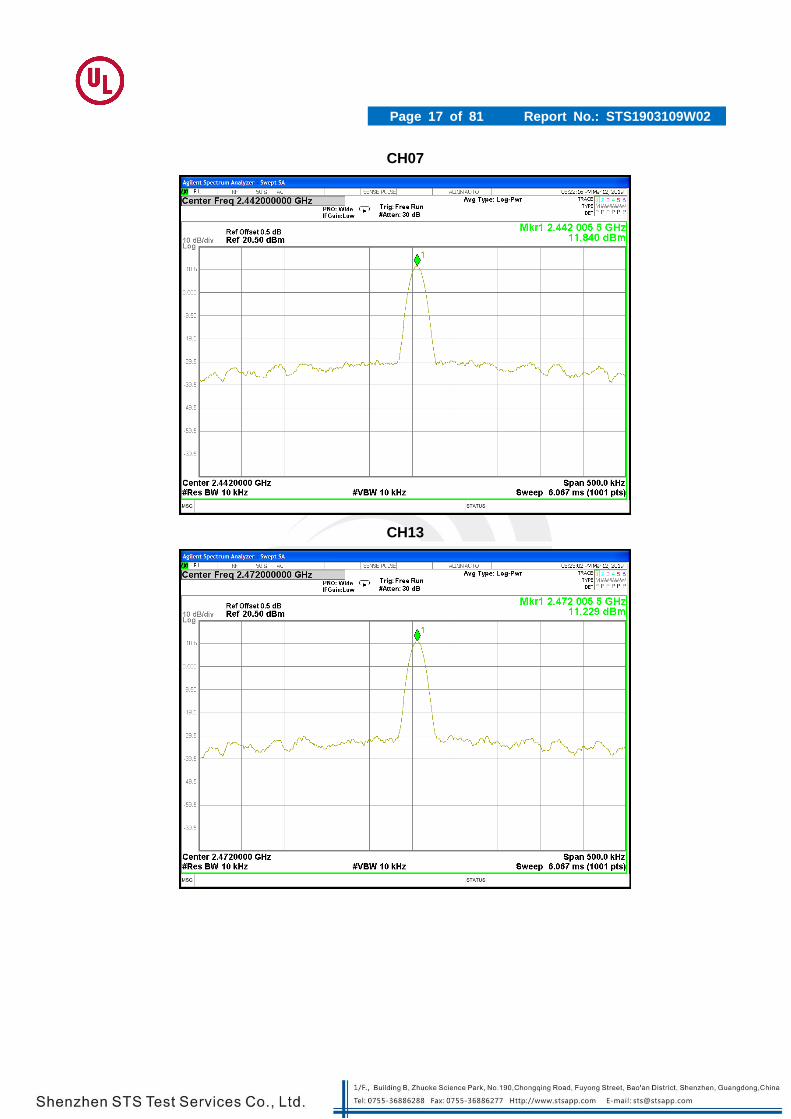
4.5 TEST RESULT
Temperature: 250C Humidity: 55 % RH
Operation Mode: Nor. Voltage
11b mode
TEST CONDITIONS
Channel Reading Tolerance Limit frequency
error Limit
MHz MHz ppm (ppm) (kHz) (KHz)
V nom (V) 3.7
2412 2412.0055 2.280 ±50 5.500 ±120
2442 2442.0055 2.252 ±50 5.500 ±120
2472 2472.0055 2.225 ±50 5.500 ±120
CH01
Page 17 of 81 Report No.: STS1903109W02
CH07
CH13

Page 18 of 81 Report No.: STS1903109W02
11g mode
TEST CONDITIONS
Channel Reading Tolerance Limit frequency
error Limit
MHz MHz ppm (ppm) (kHz) (KHz)
V nom (V) 3.7
2412 2412.0055 2.280 ±50 5.500 ±120
2442 2442.0055 2.252 ±50 5.500 ±120
2472 2472.0055 2.225 ±50 5.500 ±120
CH01

Page 19 of 81 Report No.: STS1903109W02
CH07
CH13

Page 20 of 81 Report No.: STS1903109W02
11n20 mode
TEST CONDITIONS
Channel Reading Tolerance Limit frequency
error Limit
MHz MHz ppm (ppm) (kHz) (KHz)
V nom (V) 3.7
2412 2412.0055 2.280 ±50 5.500 ±120
2442 2442.0055 2.252 ±50 5.500 ±120
2472 2472.0055 2.225 ±50 5.500 ±120
CH01

Page 21 of 81 Report No.: STS1903109W02
CH07
CH13

Page 22 of 81 Report No.: STS1903109W02
11n40 mode
TEST CONDITIONS
Channel Reading Tolerance Limit frequency
error Limit
MHz MHz ppm (ppm) (kHz) (KHz)
V nom (V) 3.7
2422 2422.0055 2.271 ±50 5.500 ±120
2442 2442.0055 2.252 ±50 5.500 ±120
2462 2462.0055 2.234 ±50 5.500 ±120
CH03

Page 23 of 81 Report No.: STS1903109W02
CH07
CH11

Page 24 of 81 Report No.: STS1903109W02
5. ANTENNAPOWER 5.1 LIMIT
Item Limits
Antenna PowerDensity
≦3mW/MHz (FH form 2400 – 2483.5 MHz) ≦10mW/MHz (OFDM,DS from2400~2483.5MHz,802.11b/g/n HT20) ≦5mW/MHz (OFDM,DS from2400~2483.5MHz,802.11n HT40)
≦10mW (Other from 2400~2483.5MHz)
Power Error +20%, -80% (Base on manufacturer declare power)
5.2 TEST PROCEDURE 1. A power meter is connected on the IF output port of the spectrum analyzer. 2. EUT turn to test frequency channel and keep continuous transmiting 3. Connected the equipment to be measured. Using the following settings of the spectrum analyzer in combination with "max hold" function, find the frequency of highest power output in the power envelope: center frequency equal to operation frequency; RBW & VBW: 1 MHz; detector mode: positive peak; averGaing: off; span: 3 times the spectrum width; amplitude: adjust for middle of the instrument' range. 4. Reading the output power from the Power meter as PEUT 5. Turn the Signal generator to frequency channel the same as the EUT 6. Using the following settings of the spectrum analyzer in combination with "max hold" function, find the frequency of highest power output in the power envelope: center frequency equal to operation frequency; RBW & VBW: 1 MHz; detector mode: positive peak; averGaing: off; span: 3 times the spectrum width; amplitude: adjust for middle of the instrument' range. 7. Turn the level of Signal generator, scan with the power meter until the power equal to PEUT, the level of Signal generator recorded as “P” 8. The antenna power of EUT is “P”. 9. EIRP power=“P”+antenna gain
5.3 TEST SETUP
5.4 TEST DEVIATION
There is no deviation with the original standard.

Page 25 of 81 Report No.: STS1903109W02
5.5 TEST RESULT
Temperature: 250C Humidity: 55 % RH
Operation Mode: Nor. Voltage-802.11b mode
Antenna PowerDensity
TEST CONDITIONS
Channel (MHz)
Ant. output POWER (dBm/MHz)
Ant.output (mW/MHz)
Declared Power
(mW/MHz)
Tolerance
%
Vnom(V) 3.7
2412 9.302 8.515 9.0000 -5.39
2442 8.752 7.502 9.0000 -16.64
2472 8.292 6.748 9.0000 -25.02
Limit :(1) Antenna PowerDensityLimit(10mW/MHz) (2) Tolerance +20%, -80% (Base on manufacturer declare Antenna PowerDensity)
Temperature: 250C Humidity: 55 % RH
Operation Mode: Nor. Voltage-802.11g mode
Antenna PowerDensity
TEST CONDITIONS
Channel (MHz)
Ant. output POWER (dBm/MHz)
Ant. output (mW/MHz)
Declared Power
(mW/MHz)
Tolerance
%
Vnom(V) 3.7
2412 8.007 6.320 6.5000 -2.77
2442 7.530 5.662 6.5000 -12.89
2472 6.914 4.914 6.5000 -24.41
Limit :(1) Antenna PowerDensityLimit(10mW/MHz) (2) Tolerance +20%, -80% (Base on manufacturer declare Antenna PowerDensity)

Page 26 of 81 Report No.: STS1903109W02
Temperature: 250C Humidity: 55 % RH
Operation Mode: Nor. Voltage-802.11n20 mode
Antenna PowerDensity
TEST CONDITIONS Channel
(MHz) Ant. output
POWER (dBm/MHz) Ant. output (mW/MHz)
Declared Power
(mW/MHz)
Tolerance
%
Vnom(V) 3.7
2412 7.930 6.209 6.5000 -4.48
2442 7.489 5.609 6.5000 -13.70
2472 6.991 5.001 6.5000 -23.05
Limit :(1) Antenna PowerDensityLimit(10mW/MHz) (2) Tolerance +20%, -80% (Base on manufacturer declare Antenna PowerDensity)
Temperature: 250C Humidity: 55 % RH
Operation Mode: Nor. Voltage-802.11n40 mode
Antenna PowerDensity
TEST CONDITIONS Channel
(MHz) Ant. output
POWER (dBm/MHz) Ant. output (mW/MHz)
Declared Power
(mW/MHz)
Tolerance
%
Vnom(V) 3.7
2422 5.095 3.232 3.5000 -7.65
2442 4.688 2.943 3.5000 -15.91
2462 3.958 2.488 3.5000 -28.92
Limit :(1) Antenna PowerDensityLimit(5mW/MHz) (2) Tolerance +20%, -80% (Base on manufacturer declare Antenna PowerDensity)

Page 27 of 81 Report No.: STS1903109W02
6. EIRP POWER
6.1 LIMIT
Item Limits
Radiation powerEIRP
FH form 2400 – 2483.5MHz,EIRP≦6.91dBm/MHz
CCK/OFDM/DBPSK (2400~2483.5MHz)
OFDM or DS other than (802.11b/g/n HT20) EIRP≦12.14 dBm/MHz
OFDM or DS other than (802.11n HT40) EIRP≦9.13dBm/MHz
Other from 2400~2483.5MHz: 12.14 dBm or less
Power Error +20%, -80% (Base on manufacturer declare power)
6.2 TEST RESULT Note: The antenna gain is less than 2.14dBi, no requirement.

Page 28 of 81 Report No.: STS1903109W02
7. OCCUPIED BANDWITH AND SPREADING BANDWIDTH
7.1 LIMIT
Item Limits
Occupied Band Width: 83.5MHz for FHSS; 26MHz for DSSS and OFDM; 38MHz for OFDM(HT 40)
Spreading Bandwidth: ≧500 kHz (FH, DS)
7.2 TEST PROCEDURES
1. EUT have transmitted the maximum modulation signal and fixed channelize ( For DSSS or OFDM Device) or continuous maximum power of hopping mode(For FHSS Device). SA set to 99% of occupied bandwidth to measure occupied bandwidth. The limit is less than 26MHz(For DSSS or OFDM Device),83.5MHz(For FHSS Device) or 38MHz (For OFDM(HT 40)).
2. SA set to 90% of occupied bandwidth to measure Spread Spectrum Bandwidth and must greater than 500kHz.
7.3 TEST SETUP
7.4 TEST DEVIATION
There is no deviation with the original standard. 7.5 EUT OPERATION DURING TEST
The EUT was programmed to be in continuously transmitting mode.
Page 29 of 81 Report No.: STS1903109W02
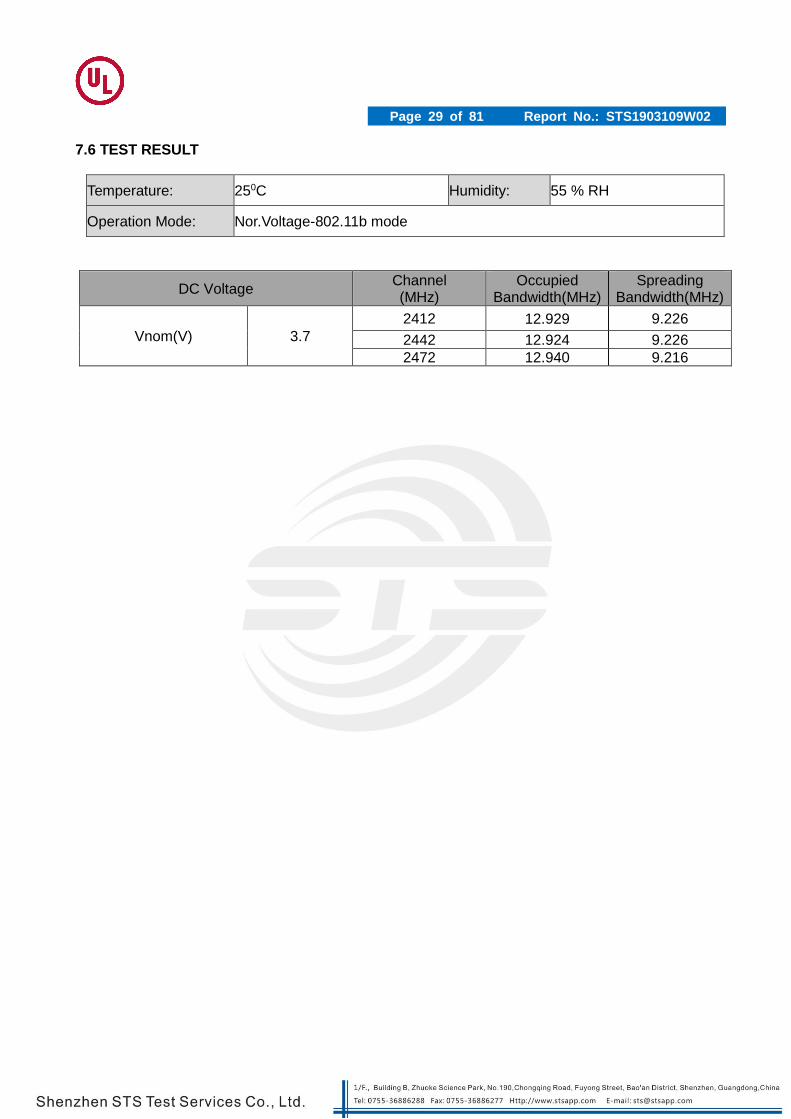
7.6 TEST RESULT
Temperature: 250C Humidity: 55 % RH
Operation Mode: Nor.Voltage-802.11b mode
DC Voltage Channel (MHz)
Occupied Bandwidth(MHz)
Spreading Bandwidth(MHz)
Vnom(V) 3.7
2412 12.929 9.226
2442 12.924 9.226
2472 12.940 9.216

Page 30 of 81 Report No.: STS1903109W02
CH1-Occupied Bandwidth (99%)-b Mode
CH1-Spread Bandwidth (90%)-b Mode

Page 31 of 81 Report No.: STS1903109W02
CH7-Occupied Bandwidth (99%)-b Mode
CH7-Spread Bandwidth (90%)-b Mode

Page 32 of 81 Report No.: STS1903109W02
CH13-Occupied Bandwidth (99%)-b Mode
CH13-Spread Bandwidth (90%)-b Mode

Page 33 of 81 Report No.: STS1903109W02
Temperature: 250C Humidity: 55 % RH
Operation Mode: Nor.Voltage-802.11g mode
DC Voltage Channel (MHz)
Occupied Bandwidth(MHz)
Spreading Bandwidth(MHz)
Vnom(V) 3.7
2412 16.289 14.482
2442 16.288 14.477
2472 16.291 14.485

Page 34 of 81 Report No.: STS1903109W02
CH1-Occupied Bandwidth (99%)-g Mode
CH1-Spread Bandwidth (90%)-g Mode

Page 35 of 81 Report No.: STS1903109W02
CH7-Occupied Bandwidth (99%)-g Mode
CH7-Spread Bandwidth (90%)-g Mode

Page 36 of 81 Report No.: STS1903109W02
CH13-Occupied Bandwidth (99%)-g Mode
CH13-Spread Bandwidth (90%)-g Mode

Page 37 of 81 Report No.: STS1903109W02
Temperature: 250C Humidity: 55 % RH
Operation Mode: Nor.Voltage-802.11n(HT20) mode
DC Voltage Channel (MHz)
Occupied Bandwidth(MHz)
Spreading Bandwidth(MHz)
Vnom(V) 3.7
2412 17.105 14.888
2442 17.093 14.903
2472 17.098 14.924

Page 38 of 81 Report No.: STS1903109W02
CH1-Occupied Bandwidth (99%)-n(HT20)
CH1-Spread Bandwidth (90%)-n(HT20)

Page 39 of 81 Report No.: STS1903109W02
CH7-Occupied Bandwidth (99%)-n(HT20)
CH7-Spread Bandwidth (90%)-N(HT20)

Page 40 of 81 Report No.: STS1903109W02
CH13-Occupied Bandwidth (99%)-n(HT20)
CH13-Spread Bandwidth (90%)- n(HT20)

Page 41 of 81 Report No.: STS1903109W02
Temperature: 250C Humidity: 55 % RH
Operation Mode: Nor.Voltage-802.11n(HT40) mode
DC Voltage Channel (MHz)
Occupied Bandwidth(MHz)
Spreading Bandwidth(MHz)
Vnom(V) 3.7
2422 35.891 31.616
2442 35.884 31.613
2462 35.888 31.620

Page 42 of 81 Report No.: STS1903109W02
CH3-Occupied Bandwidth (99%)-n(HT40)
CH3-Spread Bandwidth (90%)-n(HT40)

Page 43 of 81 Report No.: STS1903109W02
CH7-Occupied Bandwidth (99%)-n(HT40)
CH7-Spread Bandwidth (90%)-n(HT40)

Page 44 of 81 Report No.: STS1903109W02
CH11-Occupied Bandwidth (99%)-n(HT40)
CH11-Spread Bandwidth (90%)-n(HT40)

Page 45 of 81 Report No.: STS1903109W02
7.7 TEST RESULT(SPREADING FACTOR)
Spreading factor=(Spreading bandwidth) / (Frequency corresponding to transmission rate) 802.11b: Frequency corresponding to transmission rate=1.375
802.11b
Channel
(MHz)
Spread BW 90%
(MHz) Spread rate Spreading factor Limit
2412 9.226 1.375 6.710 ≧5
2442 9.226 1.375 6.710 ≧5
2472 9.216 1.375 6.702 ≧5

Page 46 of 81 Report No.: STS1903109W02
8. UNWANTED EMISSION INTENSITY MEASUREMENT
8.1 LIMIT
Item Limits
TX Spurious Emission
≦2.5 μW (30MHz≦f≦1000MHz)
≦2.5 μW (1000MHz<f≦2387MHz)
≦25 μW (2387MHz<f≦2400MHz)
≦25 μW (2483.5MHz≦f<2496.5MHz)
≦2.5 μW (2496.5MHz≦f<12500MHz)
8.2 TEST PROCEDURES The following table is the setting of Spectrum Analyzer.
Spectrum Parameter Setting
Attenuation Auto
RBW / VBW 100KHz /100KHz(Below 1GHz)
RBW / VBW 1MHz /1MHz (Above 1GHz)
Detector Peak
Trace Max Hold
Sweep Time Auto
1. EUT have transmitted the maximum modulation signal and fixed channelize. 2. Setting of SA is following as: Below 1GHz RB:100KHz / VB:100KHz Above 1GHz RB:1MHz / VB:1MHz / AT: 10dB Ref: 0dBm / Sweep time: Auto Sweep Mode: Continuous sweep / Detect mode: Positive peak Trace mode: Max hold
3. Setting of SA is following as 30MHz and stop frequency 1000MHz Then to mark peak reading value + cable loss shall be less than 0.25μW.
4. Setting of SA is following as 1000MHz and stop frequency 2387MHz Then to mark peak reading value + cable loss shall be less than 2.5μW.
5. SA adjusted to start frequency 2387MHz and stop frequency 2400MHz. Then to mark peak reading value + cable loss shall be less than 25μW.
6. SA adjusted to start frequency 2483.5MHz and stop frequency 2496.5MHz Then to mark peak reading value + cable loss shall be less than 25μW
7. SA adjusted to start frequency 2496.5MHz and stop frequency 12750MHz Then to mark peak reading value + cable loss shall be less than 2.5μW
8. Measure side band spurious as follows: For 2.4GHz band: 2374MHz~2400MHz and 2483.5MHz~2509.5MHz RBW = VBW = 30kHz, Result_Value = Meaured_ Value + 15.2 [dBm]
9. If the Result_Value is over the requirement, take total sum of 1MHz band centered at the spur frequency like ACLP measurement as Result_Value.

Page 47 of 81 Report No.: STS1903109W02
8.3 TEST SETUP
8.4 TEST DEVIATION There is no deviation with the original standard.

Page 48 of 81 Report No.: STS1903109W02
8.5 TEST RESULT
Temperature: 250C Humidity: 55 % RH
Operation Mode: Nor. Voltage-802.11b mode(CH1, CH7,CH13)
CH 1 (11b) - Band 1 (30 MHz ≦f ≦1000 MHz)

Page 49 of 81 Report No.: STS1903109W02
CH 1 (11b) - Band 2 (1000 MHz < f ≦2520 MHz)
CH 1 (11b) - Band 3 (2520 MHz ≦f < 12.75 GHz)

Page 50 of 81 Report No.: STS1903109W02
CH 7(11b) - Band 1 (30 MHz ≦f ≦1000 MHz)
CH 7(11b) - Band 2 (1000 MHz < f ≦2520 MHz)

Page 51 of 81 Report No.: STS1903109W02
CH 7(11b) - Band 3 (2520 MHz ≦f < 12.75 GHz)
CH 13(11b) - Band 1 (30 MHz ≦f ≦1000 MHz)

Page 52 of 81 Report No.: STS1903109W02
CH 13(11b) - Band 3 (2520 MHz ≦f < 12.75 GHz)
CH 13(11b) - Band 2 (1000 MHz < f ≦2520 MHz)

Page 53 of 81 Report No.: STS1903109W02
Temperature: 250C Humidity: 55 % RH
Operation Mode: Nor. Voltage-802.11g mode(CH1, CH7,CH13)
CH1(11g)- Band 1 (30 MHz ≦f ≦1000 MHz)
CH1(11g)- Band 2 (1000 MHz < f ≦2520 MHz)

Page 54 of 81 Report No.: STS1903109W02
CH 1(11g)- Band 3 (2520 MHz ≦f < 12.75 GHz)

Page 55 of 81 Report No.: STS1903109W02
CH 7(11g)- Band 1 (30 MHz ≦f ≦1000 MHz)
CH 7(11g)- Band 2 (1000 MHz < f ≦2520 MHz)

Page 56 of 81 Report No.: STS1903109W02
CH 7(11g)- Band 3 (2520 MHz ≦f < 12.75 GHz)
CH 13(11g)- Band 1 (30 MHz ≦f ≦1000 MHz)

Page 57 of 81 Report No.: STS1903109W02
CH 13(11g)- Band 2 (1000 MHz < f ≦2520 MHz)
CH 13(11g)- Band 3 (2520 MHz ≦f < 12.75 GHz)

Page 58 of 81 Report No.: STS1903109W02
Temperature: 250C Humidity: 55 % RH
Operation Mode: Nor. Voltage-802.11n(HT20) mode(CH1, CH7,CH13)
CH1 11n(HT20)- Band 1 (30 MHz ≦f ≦1000 MHz)

Page 59 of 81 Report No.: STS1903109W02
CH1 11n(HT20)- Band 2 (1000 MHz < f ≦2520 MHz)
CH1 11n(HT20)- Band 3 (2520 MHz ≦f < 12.75 GHz)

Page 60 of 81 Report No.: STS1903109W02
CH 7 11n(HT20)- Band 1 (30 MHz ≦f ≦1000 MHz)
CH 7 11n(HT20)- Band 2 (1000 MHz < f ≦2520 MHz)

Page 61 of 81 Report No.: STS1903109W02
CH 7 11n(HT20)- Band 3 (2520 MHz ≦f < 12.75 GHz)
CH 13 11n(HT20)- Band 1 (30 MHz ≦f ≦1000 MHz)

Page 62 of 81 Report No.: STS1903109W02
CH 13 11n(HT20)- Band 2 (1000 MHz < f ≦2520 MHz)
CH 13 11n(HT20)- Band 3 (2520 MHz ≦f < 12.75 GHz)

Page 63 of 81 Report No.: STS1903109W02
Temperature: 250C Humidity: 55 % RH
Operation Mode: Nor. Voltage-802.11n(HT40) mode(CH3, CH7,CH11)
CH3 11n(HT40)- Band 1 (30 MHz ≦f ≦1000 MHz)

Page 64 of 81 Report No.: STS1903109W02
CH3 11n(HT40)- Band 2 (1000 MHz < f ≦2520 MHz)
CH3 11n(HT40)- Band 3 (2520 MHz ≦f < 12.75 GHz)

Page 65 of 81 Report No.: STS1903109W02
CH 7 11n(HT40)- Band 1 (30 MHz ≦f ≦1000 MHz)
CH 7 11n(HT40)- Band 2 (1000 MHz < f ≦2520 MHz)

Page 66 of 81 Report No.: STS1903109W02
CH 7 11n(HT40)- Band 3 (2520 MHz ≦f < 12.75 GHz)
CH 11 11n(HT40)- Band 1 (30 MHz ≦f ≦1000 MHz)

Page 67 of 81 Report No.: STS1903109W02
CH 11 11n(HT40)- Band 2 (1000 MHz < f ≦2520 MHz)
CH 11 11n(HT40)- Band 3 (2520 MHz ≦f < 12.75 GHz)

Page 68 of 81 Report No.: STS1903109W02
9. IMITATION OF COLLATERAL EMISSION OF RECEIVER MEASUREMENT
9.1 LIMIT
Item Limits
RX Spurious Emission:
≦4nW (f<1GHz)
≦20nW (1GHz≦f)
9.2 TEST PROCEDURES
The following table is the setting of Spectrum Analyzer.
Spectrum Parameter Setting
Attenuation Auto
RBW 100 kHz (below 1GHz emissions) 1 MHz (above 1GHz emissions)
VBW 100 kHz (below 1GHz emissions) 1 MHz (above 1GHz emissions)
Detector Peak
Trace Max Hold
Sweep Time Auto
1. EUT have the continuous reception mode and fixed only one channelize. 2. Setting of SA is following as RB / VB: 100 kHz (below 1GHz emissions) / 1 MHz
(above 1GHz emissions) /Sweep time: Auto / Sweep Mode: Continuous sweep / Detect mode: Positive peak / Trace mode: Max hold 3. SA set RB: 100kHz and VB: 100kHz. Then adjust to start frequency 30MHz and
stop frequency 1000MHz. Search to mark peak reading value + cable loss shall be less than 4nW
4. SA set RB: 1MHz and VB: 1MHz. Then adjust to start frequency 1000MHz and stop frequency 12500MHz. Search to mark peak reading value + cable loss shall be less than 20nW
5. If power level of lower emissions are more than 1/10 of limit (.0.4nW for f < 1GHz, 2nW for f >= 1GHz), all those are to be indicated in the 2nd and 3rd lines. If others are 1/10 or less more of the limit, no necessary to be indicated.

Page 69 of 81 Report No.: STS1903109W02
9.3 TEST RESULT
Temperature: 250C Humidity: 55 % RH
Operation Mode: Nor. Voltage-11b RX Mode
RX- Band 1 (30 MHz ≦f < 1000 MHz)
RX- Band 2 (1000 MHz ≦f < 12750 MHz)

Page 70 of 81 Report No.: STS1903109W02
Temperature: 250C Humidity: 55 % RH
Operation Mode: Nor. Voltage-11g RX Mode
RX- Band 1 (30 MHz ≦f < 1000 MHz)
RX- Band 2 (1000 MHz ≦f < 12750 MHz)

Page 71 of 81 Report No.: STS1903109W02
Temperature: 250C Humidity: 55 % RH
Operation Mode: Nor.Voltage-11n20 RX Mode
RX- Band 1 (30 MHz ≦f < 1000 MHz)
RX- Band 2 (1000 MHz ≦f < 12750 MHz)

Page 72 of 81 Report No.: STS1903109W02
Temperature: 250C Humidity: 55 % RH
Operation Mode: Nor.Voltage-11n40 RX Mode
RX- Band 1 (30 MHz ≦f < 1000 MHz)
RX- Band 2 (1000 MHz ≦f < 12750 MHz)

Page 73 of 81 Report No.: STS1903109W02
10. TRANSMISSION RADIATION ANGLE WIDTH (3DB BEAMWIDTH) MEASUREMENT
10.1 LIMIT
Item Limits
3dB antenna beam width
e ≦ 360/A (The A is 10 in maximum)
A = {EIRP Power [mW/MHz] /{2.14dBi+output power(10mW /MHz, 3mW/MHz)} Shall be 1 when A is lower than 1
10.2 TEST PROCEDURES
Spectrum Parameter Setting
Attenuation Auto
Span Frequency 0 MHz
RBW 1 MHz
VBW 1 kHz
Detector Peak
Trace Max Hold
Sweep Time Auto
1. Set EUT and measuring antenna at the same height and roughly facing each other. 2. Set spectrum analyzer with condition in section 4.7.2 and tune reference level to
observe receving signal position. 3. Rotate directions of the EUT horizontally and ertically to find the maximum
receiving power. 4. Move the measuring antenna height up and down within ± 50cm of EUT height and
swing it to find the maximum output of measuing antenna. “E” is the half-power beam width (angle between two points at which radiated power becomes 1/2)
5. Caluate permitted radiation angle in horizontal and vertical using EIRP measured in another test method.
6. Calculate 3dB antenna beam width by the formula below 360/A The A is 10 in maximum).
e ≦ 360/A (The A is 10 in maximum)
A = {EIRP Power [mW/MHz] /{2.14dBi+output power(10mWMHz, 3mW/MHz)} Shall be 1 when A is lower than 1

Page 74 of 81 Report No.: STS1903109W02
10.3 TEST SETUP
10.4 TEST DEVIATION There is no deviation with the original standard.
10.5 EUT OPERATION DURING TEST The EUT was programmed to be in continuously transmitting mode.
10.6 TEST RESULT Note: The antenna gain is less than 2.14dBi, no requirement.

Page 75 of 81 Report No.: STS1903109W02
11. RADIO INTERFERENCE PREVENTION CAPABILITY MEASUREMENT
11.1 LIMIT
Item Limits
Identification code ≧48 bits
11.2 MEASURING ID CODE SOFTWARE
Item Limits
MAC IP List MAC Scan
11.3 TEST PROCEDURES
1. In the case that the EUT has the function of automatically transmitting the identification code: a. Transmit the predetermined identification codes form EUT. b. Check the transmitted identification codes with the demodulator.
2. In the case of receiving the identification ocde: a. Transmit the predetermined identification codes form the counterpart. b . Check if communication is normal. c. Transmit the signals other than predetermined ID codes form the counterpart. d. check if the EUT stops the transmission, or if it displays that idnetification codes are different from the predetermined ones.
11.4 TEST SETUP
11.5 TEST DEVIATION There is no deviation with the original standard.
11.6 EUT OPERATION DURING TEST
The EUT was programmed to be in normal transmitting mode.

Page 76 of 81 Report No.: STS1903109W02
11.7 TEST RESULT OF RADIO INTERFERENCE PREVENTION CAPABILIT
Note: The MAC Address is D5:61:95:3B:63:BA.

Page 77 of 81 Report No.: STS1903109W02
12. CARRIER SENSE CAPABILITY
12.1 INTERFERENCE PREVENTION FUNCTION
12.2 TEST REQUIREMENT
MIC Notice No.88 Appendix No.43
Article 2, Paragraph 1, Item 19 Rules Section 10
12.3 TEST PROCEDURE
1. SG adjusted the frequency as same as the EUT transmitted signal and emitted the absence of
modulation from SG and power level is (on 22.79+G-20*log(f)dBm)(G is the antenna gain,f is the test
frequency).
2. turn off the RF signal of the SG.
3. EUT have transmitted the maximum modulation signal and fixed channelize.
4. Setting of SA :RBW/VBW=1MHz/1MHz,Span=0MHz,Sweep time=auto,Sweep mode=continuous,
Detect mode=positive peak
5. SG RF signal on.
6. EUT shall be stop the transmitted any signal and SG RF signal off, the EUT will be continuous

Page 78 of 81 Report No.: STS1903109W02
12.4 TEST RESULT
Temperature: 250C Humidity: 55 % RH
Test result: CONFORM
802.11n(HT40) mode Test polt
Channel 3 TX-2422 Worst Mode
Normal emission Stop signal generator
Injected signal generator

Page 79 of 81 Report No.: STS1903109W02
Channel 7 TX-2442 Worst Mode
Channel 11 TX-2462Worst Mode
Normal emission Stop signal generator
Injected signal generator
Normal emission
Stop signal generator
Injected signal generator

Page 80 of 81 Report No.: STS1903109W02

Page 81 of 81 Report No.: STS1903109W02
13. EUT TEST PHOTO Note: See test photos in setup photo document for the actual connections between Product and support equipment.
※※※※※END OF THE REPORT※※※※※