report of the aapm task group no. 105: issues associated with
TRANSCRIPT

Report of the AAPM Task Group No. 105: Issues associatedwith clinical implementation of Monte Carlo-based photonand electron external beam treatment planning
Indrin J. Chettya!
University of Michigan, Ann Arbor, Michigan 48109and University of Nebraska Medical Center, Omaha, Nebraska 68198-7521
Bruce CurranUniversity of Michigan, Ann Arbor, Michigan 48109
Joanna E. CyglerOttawa Hospital Regional Cancer Center, Ottawa, Ontario K1H 1C4, Canada
John J. DeMarcoUniversity of California, Los Angeles, Callifornia 90095
Gary EzzellMayo Clinic Scottsdale, Scottsdale, Arizona 85259
Bruce A. FaddegonUniversity of California, San Francisco, California 94143
Iwan KawrakowNational Research Council of Canada, Ottawa, Ontario K1A 0R6, Canada
Paul J. KeallStanford University Cancer Center, Stanford, California 94305-5847
Helen LiuUniversity of Texas MD Anderson Cancer Center, Houston, Texas 77030
C.-M. Charlie MaFox Chase Cancer Center, Philadelphia, Pennsylvania 19111
D. W. O. RogersCarleton University, Ottawa, Ontario K1S 5B6, Canada
Jan SeuntjensMcGill University, Montreal, Quebec H3G 1A4, Canada
Daryoush Sheikh-BagheriThe Regional Cancer Center, Erie, Pennsylvania 16505
Jeffrey V. SiebersVirginia Commonwealth University, Richmond, Virginia 23298
!Received 11 April 2006; revised 11 July 2007; accepted for publication 18 September 2007;published 27 November 2007"
The Monte Carlo !MC" method has been shown through many research studies to calculate accuratedose distributions for clinical radiotherapy, particularly in heterogeneous patient tissues where theeffects of electron transport cannot be accurately handled with conventional, deterministic dosealgorithms. Despite its proven accuracy and the potential for improved dose distributions to influ-ence treatment outcomes, the long calculation times previously associated with MC simulationrendered this method impractical for routine clinical treatment planning. However, the developmentof faster codes optimized for radiotherapy calculations and improvements in computer processortechnology have substantially reduced calculation times to, in some instances, within minutes on asingle processor. These advances have motivated several major treatment planning system vendorsto embark upon the path of MC techniques. Several commercial vendors have already released orare currently in the process of releasing MC algorithms for photon and/or electron beam treatmentplanning. Consequently, the accessibility and use of MC treatment planning algorithms may wellbecome widespread in the radiotherapy community. With MC simulation, dose is computed sto-chastically using first principles; this method is therefore quite different from conventional dosealgorithms. Issues such as statistical uncertainties, the use of variance reduction techniques, the
4818 4818Med. Phys. 34 „12…, December 2007 0094-2405/2007/34„12…/4818/36/$23.00 © 2007 Am. Assoc. Phys. Med.

ability to account for geometric details in the accelerator treatment head simulation, and otherfeatures, are all unique components of a MC treatment planning algorithm. Successful implemen-tation by the clinical physicist of such a system will require an understanding of the basic principlesof MC techniques. The purpose of this report, while providing education and review on the use ofMC simulation in radiotherapy planning, is to set out, for both users and developers, the salientissues associated with clinical implementation and experimental verification of MC dose algo-rithms. As the MC method is an emerging technology, this report is not meant to be prescriptive.Rather, it is intended as a preliminary report to review the tenets of the MC method and to providethe framework upon which to build a comprehensive program for commissioning and routinequality assurance of MC-based treatment planning systems. © 2007 American Association ofPhysicists in Medicine. #DOI: 10.1118/1.2795842$
Key words: Monte Carlo dose calculation, clinical treatment planning, experimental verification
TABLE OF CONTENTS
I. INTRODUCTION. . . . . . . . . . . . . . . . . . . . . . . . . . . . 4819I.A. Motivation. . . . . . . . . . . . . . . . . . . . . . . . . . . . . 4819I.B. Objectives for the report. . . . . . . . . . . . . . . . . 4820I.C. Organization of the report. . . . . . . . . . . . . . . . 4820
II. THE MONTE CARLO METHOD INRADIOTHERAPY DOSE CALCULATIONS. . . . . 4820II.A. Definition of the MC method and historical
background. . . . . . . . . . . . . . . . . . . . . . . . . . . . 4820II.B. Monte Carlo simulation of electron and
photon transport. . . . . . . . . . . . . . . . . . . . . . . . 4821II.B.1. Analog simulations. . . . . . . . . . . . . . . . . . . 4822II.B.2. Condensed history simulations. . . . . . . . . . 4822
II.C. Overview of Monte Carlo-basedradiotherapy dose calculations. . . . . . . . . . . . . 4823
II.D. Variance reduction techniques and efficiencyenhancing methods. . . . . . . . . . . . . . . . . . . . . . 4824
III. MONTE CARLO SIMULATION OFRADIATION TRANSPORT INACCELERATORS AND PATIENTS. . . . . . . . . . . . 4825
III.A. Review of current Monte Carlo codes. . . . . . . 4825III.B. Accelerator treatment head simulation. . . . . . 4826
III.B.1. Sensitivity of simulations to electronbeam and other parameters. . . . . . . . . . . . . 4826
III.B.2. Electron beam specifics. . . . . . . . . . . . . . . . 4828III.C. Modeling of the linear accelerator treatment
head. . . . . . . . . . . . . . . . . . . . . . . . . . . . . . . . . . 4829III.C.1. General schemes. . . . . . . . . . . . . . . . . . . . . 4829III.C.2. Patient-specific beam modifiers. . . . . . . . . . 4831III.C.3. Output ratios. . . . . . . . . . . . . . . . . . . . . . . . 4831III.C.4. Dose buildup. . . . . . . . . . . . . . . . . . . . . . . . 4831
III.D. Treatment planning: MC-based patientcalculations. . . . . . . . . . . . . . . . . . . . . . . . . . . . 4832
III.D.1. Statistical uncertainties. . . . . . . . . . . . . . . . 4832III.D.2. Dose prescriptions and monitor unit
calculation. . . . . . . . . . . . . . . . . . . . . . . . . . 4834III.D.3. CT-to-material conversions. . . . . . . . . . . . . 4835III.D.4. Dose-to-water and dose-to-medium. . . . . . 4835III.D.5. IMRT dose calculation and optimization.. 4837III.D.6. Voxel size effects. . . . . . . . . . . . . . . . . . . . . 4838
III.D.7. Cross sections. . . . . . . . . . . . . . . . . . . . . . . 4839III.E. Experimental verification. . . . . . . . . . . . . . . . . 4839
III.E.1. Introduction. . . . . . . . . . . . . . . . . . . . . . . . . 4839III.E.2. Previous work. . . . . . . . . . . . . . . . . . . . . . . 4839III.E.3. Types of verification experiments. . . . . . . . 4839III.E.4. Verification of the Monte Carlo transport
algorithm in phantom. . . . . . . . . . . . . . . . . 4840III.E.5. Dose buildup region. . . . . . . . . . . . . . . . . . 4841III.E.6. Output ratios. . . . . . . . . . . . . . . . . . . . . . . . 4841III.E.7. Electron beams. . . . . . . . . . . . . . . . . . . . . . . 4841III.E.8. Measurement uncertainties. . . . . . . . . . . . . 4842III.E.9. Example experimental tests. . . . . . . . . . . . . 4842
III.E.10. Timing issues. . . . . . . . . . . . . . . . . . . . . . . . 4842IV. CLINICAL IMPLICATIONS OF MONTE
CARLO-CALCULATED DOSEDISTRIBUTIONS. . . . . . . . . . . . . . . . . . . . . . . . . . . 4843
IV.A. Introduction. . . . . . . . . . . . . . . . . . . . . . . . . . . . 4843IV.B. Clinical examples. . . . . . . . . . . . . . . . . . . . . . . 4844
IV.B.1. Photon beam treatment planning. . . . . . . . . 4845IV.B.2. Electron beam treatment planning. . . . . . . 4845
IV.C. Association of Monte Carlo calculated dosedistributions with clinical outcome. . . . . . . . . 4846
V. SUMMARY. . . . . . . . . . . . . . . . . . . . . . . . . . . . . . . . 4846V.A. Treatment head simulation. . . . . . . . . . . . . . . . 4846V.B. Patient simulation. . . . . . . . . . . . . . . . . . . . . . . 4846
V.B.1. Statistical uncertainties. . . . . . . . . . . . . . . . 4846V.B.2. Variance reduction techniques, efficiency
enhancing methods, and other parameters.. 4847V.B.3. Dose prescriptions. . . . . . . . . . . . . . . . . . . . 4847V.B.4. CT-to-material conversions. . . . . . . . . . . . . 4847V.B.5. Dose-to-water and dose-to-medium. . . . . . 4847
V.C. Experimental verification. . . . . . . . . . . . . . . . . 4847V.C.1. Examples of specific tests. . . . . . . . . . . . . . 4847V.C.2. Verification calculations. . . . . . . . . . . . . . . . 4847V.C.3. Measurement uncertainties. . . . . . . . . . . . . 4847
I. INTRODUCTION
I.A. Motivation
The accuracy of dose calculations is crucial to the quality oftreatment planning and consequently to the doses deliveredto patients undergoing radiation therapy.1 Among other fac-
4819 Chetty et al.: AAPM Task Group Report No. 105: Monte Carlo-based treatment planning 4819
Medical Physics, Vol. 34, No. 12, December 2007
tors, dose calculations form an integral component in opti-mizing the therapeutic gain, i.e., maximizing the dose to thetumor for a given normal-tissue dose, for patients treatedwith radiation. Although the clinical benefit of more accuratedose distributions !i.e., how the improved dose distributionswill affect tumor recurrence, i.e., local control, and normaltissue complications" has not been adequately quantified andrequires further investigation, evidence exists that dose dif-ferences on the order of 7% are clinically detectable.2 More-over, several studies have shown that 5% changes in dosecan result in 10%!20% changes in tumor control probability!TCP" or up to 20–30% changes in normal tissue complica-tion probabilities !NCTP" if the prescribed dose falls alongthe steepest region of the dose-effect curves.3–5 Readers in-terested in further understanding the need for heterogeneitycorrections, among other topics related to dose calculations,are encouraged to read the AAPM Report No. 85,1 where acomprehensive review of tissue heterogeneity corrections formegavoltage photon beams is provided.
In this report we focus our attention on the Monte Carlo!MC" method, a dose calculation algorithm known to be veryaccurate when used properly for treatment planning in het-erogeneous patient tissues. The issue of lengthy calculationtimes has traditionally led to the MC method being viewed inthe medical physics community as a clinically unfeasible ap-proach. However, the development of MC codes optimizedfor radiotherapy calculations as well as the availability ofmuch faster and affordable computers, have substantially re-duced processing times. These significant advances have ledto the clinical use of MC algorithms at some treatment cen-ters and the promised availability of MC photon/electronplanning modules among several commercial treatment plan-ning vendors.
In light of the above considerations, MC treatment plan-ning is quickly becoming a reality. An introductory report forthe medical physics community on the understanding, imple-mentation, testing, and use of MC algorithms is thereforewarranted.
I.B. Objectives for the report
We intend this document to be a preliminary report withthe following objectives: !a" to provide an educational re-view of the physics of the MC method and how it is appliedin external beam radiotherapy dose calculations, !b" to de-scribe the role of the MC method in external beam radio-therapy treatment planning process: from the interaction ofelectrons in the target of the linear accelerator to the deposi-tion of dose in the patient tissues, !c" to describe the issuesassociated with MC dose calculation within the patient-specific geometry, !d" to discuss the issues associated withexperimental verification of MC algorithms, and !e" to dis-cuss the clinical implications of MC calculated dose distri-butions.
We expect that areas of concern outlined in this reportwill be further investigated and that more detailed reportsproviding recommendations on the major issues will beforthcoming.
I.C. Organization of the report
Following the introductory section !Sec. I" we begin inSec. II with a review of the MC method as it applies tophoton and electron transport. We include in this section anoverview of MC simulation from the accelerator treatmenthead to the patient as well as a discussion of variance reduc-tion techniques and efficiency-enhancing methods integral toMC calculations in radiotherapy. Section III begins with areview of the major MC codes being used in clinical appli-cation and is followed by detailed discussions on acceleratortreatment head modeling and patient-specific treatment plan-ning. This section concludes with the topic of experimentalverification, in which guidance is provided on the types oftests needed to verify the accuracy of MC dose calculationalgorithms. In Sec. IV we provide a review of recent studiesdemonstrating the potential clinical impact of MC dose cal-culations in comparison with conventional algorithms. Fi-nally, we conclude in Sec. V with a summary of the recom-mendations from this task group report.
II. THE MONTE CARLO METHOD INRADIOTHERAPY DOSE CALCULATIONS
II.A. Definition of the MC method and historicalbackground
Most generally, the MC technique is a statistical methodfor performing numerical integrations. MC simulations areemployed in many areas of science and technology. Althougha method based on random sampling was discussed as earlyas 1777 by Buffon,6 the MC technique as we know it todaywas first developed and named at the end of the secondworld war. The motivation was to apply MC techniques toradiation transport, specifically for nuclear weapons.7 Thedriving forces for the initial idea appear to have been Stanis-law Ulam and John von Neumann who saw the developmentof ENIAC, the first electronic computer, as an ideal oppor-tunity to develop new applications of statistical sampling.The developments of MC techniques and computers havebeen closely intertwined ever since, with an exponential in-crease of the application of MC simulations since digitalcomputers became widely available in the 1950s and 1960s.
Modeling of particle transport problems is ideally suitedfor the use of MC methods and has been described by Rogersand Bielajew as follows: “The Monte Carlo technique for thesimulation of the transport of electrons and photons thoughbulk media consists of using knowledge of the probabilitydistributions governing the individual interactions of elec-trons and photons in materials to simulate the random trajec-tories of individual particles. One keeps track of physicalquantities of interest for a large number of histories to pro-vide the required information about the average quantities.”8
As a technique for calculating dose in a patient the underly-ing physical basis is much simpler in concept than analyticalgorithms because the MC method consists of a straightfor-ward simulation of reality and does not involve complexapproximations nor models of dose deposition, but only aknowledge of the physics of the various interactions which
4820 Chetty et al.: AAPM Task Group Report No. 105: Monte Carlo-based treatment planning 4820
Medical Physics, Vol. 34, No. 12, December 2007

have been well understood for over 50 years in most cases.While some of these interactions may be complex to simu-late in detail, the basic ideas of each interaction, e.g., anelectron giving off a bremsstrahlung photon, are well under-stood by medical physicists and, hence, the overall process iseasy to comprehend.
Although MC was used in several particle physics appli-cations to simulate electron-photon showers in the 1950s, theseminal paper in the field was that of Berger in 1963,9 inwhich he described the condensed history technique for elec-tron transport. This technique is the basis of all modernelectron-photon transport MC codes relevant to medicalphysics. The ETRAN code, based on these ideas10 was devel-oped by Berger and Seltzer and now forms the basis of elec-tron transport in the MCNP code.11 The release of the EGS4
MC code system in 198512 served as a catalyst for the appli-cation of the MC method in radiotherapy calculations of doseand dosimeter response. The work of Petti et al.,13 Mohan etal.,14 and Udale15 being early examples of the use of the EGS
MC code system12,16,17 to simulate medical linear accelera-tors. Even without the direct use of MC simulations, the MCmethod already plays a significant role in radiotherapy treat-ment planning since the energy deposition kernels used inconvolution/superposition algorithms have been calculatedusing MC techniques. Linear accelerator calibration proto-cols !e.g., AAPM’s TG-51"18 use factors derived from MCsimulations. MC-based calculations are also used in the de-sign of treatment head components.19,20
Although it has only recently become practical, for overtwo decades the application of MC techniques to radiationtreatment planning has been quite clear.21,22 The widely usedBEAM code system23 is a pair of EGS4 !now EGSnrc"17 usercodes for simulating radiation transport in accelerators and inpatients represented by CT data sets. These relatively easy touse tools have sparked intense research in MC-based radio-therapy treatment planning and have lead to two comprehen-sive reviews of accelerator simulations by Ma and Jiang24
and Verhaegen and Seuntjens.25 Kawrakow and Fippel,among others, have provided the breakthroughs which havemade clinical treatment planning feasible, as discussed inSec. III A. The fast MC codes being developed commerciallyare almost all based on the results of this collaboration. Asthis report is being written, the first commercial MC systemshave already been introduced into routine clinical treatmentplanning for electrons26 and photons.27
II.B. Monte Carlo simulation of electron and photontransport
The following material represents a very brief introduc-tion into the MC simulation of electron and photon transport.For more details the reader is referred to the reviews avail-able in the literature.8,28–31 Another source for detailed infor-mation is the documentation accompanying some of the gen-eral purpose codes, for instance, the EGSnrc,17
MCNP,32 andGEANT4 !Ref. 33" manuals, and the PENELOPE paper.34
In the energy range of interest for external beam radio-therapy !megavoltage range", photons interact with surround-
ing matter via four main processes: incoherent !Compton"scattering with atomic electrons, pair production in thenuclear or electron electromagnetic field, photoelectric ab-sorption, and coherent !Rayleigh" scattering. The first threecollision types transfer energy from the photon radiation fieldto electrons or positrons. In most cases Compton scattering isthe dominant interaction, although pair production becomesincreasingly important with increasing energy, and may evendominate at higher energies in high-Z components of thetreatment head of medical linear accelerators.
When electrons traverse matter, they undergo a largenumber of elastic interactions and lose energy by two mainprocesses: inelastic collisions with atoms and molecules andradiative interactions. Inelastic collisions result in excitationsand ionizations. Ionizations lead to secondary electrons,sometimes referred to as “! particles”. Radiative energylosses, which occur in the form of bremsstrahlung and posi-tron annihilation, transfer energy back to photons and lead tothe coupling of the electron and photon radiation fields. Onetherefore speaks of coupled electron-photon showers.
The electron-photon macroscopic radiation field can bedescribed mathematically by a coupled set of integrodiffer-ential transport equations. These transport equations are pro-hibitively complicated thereby excluding an analytical treat-ment except under severe approximations. The MCtechnique is a solution method that can be applied for anyenergy range and underlying geometry and material compo-sition.
A solution of the transport problem of particles in matter,which is exact within the existing knowledge of the elemen-tary collision processes, can be obtained by an analog MCsimulation. In an analog simulation all particle interactionswith surrounding atoms and molecules are explicitly simu-lated, including those of secondary particles created in thecollisions. An analog MC technique is therefore a faithfulsimulation of physical reality on a digital computer: particles!photons for example" are “born” according to distributionsdescribing the source, they travel a certain distance, deter-mined by a probability distribution, to the site of a collision,and scatter into another energy and/or direction state, possi-bly creating additional particles. These photons eventually“die” as a result of pair production or photoelectric events orwhen they Compton scatter to energies below a predeter-mined low-energy photon cutoff, often called PCUT. Analogsimulations, often referred to as “event-by-event” or“interaction-by-interaction” techniques, are typically usedfor the transport of neutral particles. The analog simulationof charged particle transport is not practical, due to the largenumber of interactions they undergo until locally absorbed asthe energy of the charged particle falls below the predeter-mined low-energy limit for tracking charged particles, oftencall ECUT. All general purpose MC codes therefore employcondensed history schemes for charged particle transport,discussed in more detail in Sec. II B 2.
Within a MC simulation, quantities of interest can becomputed by averaging over a given set of particle showers!also referred to as “histories,” “cases,” “trajectories,” or“tracks”". One can calculate both observable !measurable"
4821 Chetty et al.: AAPM Task Group Report No. 105: Monte Carlo-based treatment planning 4821
Medical Physics, Vol. 34, No. 12, December 2007

quantities, such as dose or a particle spectrum, and quantitiesthat cannot easily be measured such as the fraction of par-ticles originating from a certain component of the treatmenthead, the dose fraction due to scattered photons, etc. Al-though there are techniques for scoring quantities at a pointwhen using Monte Carlo techniques, in treatment planningapplications, it is usual to score quantities !dose mainly" av-eraged over some finite volume or voxel. As the voxel size isincreased, for a given statistical uncertainty the total calcu-lation time will decrease, but the spatial resolution is reduced!see Sec. III D 6 for more discussion". Another important as-pect of MC calculations is the presence of statistical uncer-tainties due to the statistical nature of the method, which isdiscussed in more detail in Sec. III D 1.
II.B.1. Analog simulations
An analog simulation of particle transport consists of fourmain steps:
!1" Select the distance to the next interaction.!2" Transport the particle to the interaction site taking into
account geometry constraints.!3" Select the interaction type.!4" Simulate the selected interaction.
Steps 1–4 are repeated until the original particle and allsecondary particles leave the geometry or are locally ab-sorbed. A particle is considered to be locally absorbed whenits energy falls below a specified threshold energy.
Step 1 is based on the probability, p!r"dr, that a particleinteracts in an interval dr at a distance r from its initialposition
p!r"dr = e!"r"dr , !1"
where " is the linear attenuation coefficient !number of in-teractions per unit length". A random distance r distributedaccording to p!r" can be sampled using the so-called inverse-transform method, which equates the cumulative probabilityof p!r" with a random number # distributed uniformly be-tween zero and unity
%0
r
p!r!"dr! = # ! r = !ln!1 ! #"
". !2"
Step 2 involves basic ray tracing, which requires a geom-etry model that can provide the medium and mass density ofa region together with a computation of the distance to thenext geometry boundary along the particle trajectory.
Step 3 is similar to step 1 except that now the probabilitydistribution function is discrete, i.e., it involves a fixed num-ber of final states i, corresponding to an interaction of type i.Suppose that the cross section for interaction of type i isdenoted by $i and the total cross section by $=%$i. A directapplication of the inverse-transform method for n interactiontypes yields interaction 1 if #&$1 /$, else interaction 2 if #& !$1+$2" /$, else interaction n, if #& !$1+$2+ ¯ +$n" /$.
Perhaps the most difficult part is step 4, where one mustsample energy/direction changes from the differential cross
section of the selected process. The manuals of the populargeneral purpose codes17,32–34 provide details of the methodsemployed for the relevant photon interactions.
Based on the above discussion it should be clear that ananalog MC simulation is conceptually quite straightforward.
II.B.2. Condensed history simulations
The condensed history technique was first described com-prehensively in the pioneering work by Berger.9 It is basedon the observation that the vast majority of electron interac-tions lead to very small changes in the electron energy and/ordirection. Many such “small-effect” interactions can there-fore be grouped into relatively few condensed history “steps”and their cumulative effect taken into account by samplingenergy, direction, and position changes from appropriate dis-tributions of grouped single interactions, e.g., multiple scat-tering, stopping power, etc. Berger defined two main classesof condensed history implementations. In a class I scheme allcollisions are subject to grouping. The effect of secondaryparticle creation above specified threshold energies are takeninto account after the fact !i.e., independently of the energyactually lost during the step" by setting up and transportingthe appropriate number of secondary particles. In this waythe correlation between large energy losses and secondaryparticle creation is lost. In a class II scheme interactions aredivided into “hard” !sometimes also referred to as “cata-strophic”" and “soft” collisions. Soft collisions are subject togrouping as in a class I scheme; hard collisions are explicitlysimulated in an analog manner.
A class II scheme can be described with the same fourbasic steps that make up an analog simulation. The two maindifferences are that only hard collisions are included and thatstep 2 is much more difficult because the particles do notmove on straight lines and because it involves the selectionof energy, direction, and position changes from multiple scat-tering distributions. It is also frequently necessary to dividethe distance between catastrophic interactions into shortercondensed history steps to guarantee the accuracy of thesimulation. As in an analog simulation there is a transportthreshold energy. Particle transport thresholds are often thesame as the particle production thresholds dividing hard andsoft collisions, but this is not a necessary condition.
A class II MC simulation is illustrated in Fig. 1. The upperportion shows a complete electron track including secondaryelectrons and photons !shown with dashed lines and not in-cluding their interactions" with energies above the hard col-lision thresholds. The lower portion is a magnified view ofthe shaded box. The actual curved path has been simulatedusing four condensed history steps. The filled circles andarrows show the positions and directions at the beginning ofthe steps. The shaded area around the electron track indicatesthe region where the energy of subthreshold secondary par-ticles is in reality deposited. If this volume is small comparedto the calculation resolution !i.e., voxel size in the case ofradiotherapy calculations", energy deposition can be consid-ered local and modeled using a restricted stopping poweralong the electron track. Note that the initial and final posi-
4822 Chetty et al.: AAPM Task Group Report No. 105: Monte Carlo-based treatment planning 4822
Medical Physics, Vol. 34, No. 12, December 2007

tions of a step are not connected in the figure to highlight thefact that a condensed history implementation does not pro-vide information on how the particle goes from A to B !thecurved dashed line connecting A and B is a more realisticrepresentation of the trajectory than a straight line from A toB". This becomes important when the scoring grid is not thesame as the underlying geometry grid or when a single con-densed history step traverses more than one geometrical re-gion as in some of the fast MC codes specialized for use inradiotherapy.35–39 This consideration highlights another im-portant aspect of a condensed history simulation, namely theway the transport is performed in the vicinity of or acrossboundaries between different regions. The EGSnrc code, forinstance, utilizes single scattering !i.e., analog" simulationwithin a certain perpendicular distance from an interface.40
Although this approach is necessary for accurate simulationsof certain types of geometries, it is generally not needed fortypical radiotherapy calculations.
Although the condensed history technique makes use ofpractical MC simulations possible, it introduces the step sizeas an artificial parameter. Dependencies of the calculated re-sults on the step size have become known as step-sizeartifacts.41 Step-size artifacts were a major factor in the earlyyears of most general purpose MC codes. Due to significanttheoretical developments in the nineties the condensed his-tory technique is now well understood.42,43 This has lead tothe development of high accuracy condensed historyimplementations40,44 and faster MC codes that can computedose distributions with accuracy comparable to traditionalMC packages in a small fraction of the time.35–39,45
With charged particle transport one stops tracking the par-ticle’s movement at some low-energy cutoff and the choiceof the cutoff can affect the calculation in two importantways. The higher the value of the cutoff, the faster the cal-culation; this can improve the calculation speed significantly.On the other hand, unless great care is taken, stopping at toohigh a cutoff energy can distort the dose distribution sincethe “stopped” charged particle might have deposited energysome distance from where its trajectory was terminated.Thus care must be taken in selecting an energy cutoff.
II.C. Overview of Monte Carlo-based radiotherapydose calculations
It is possible to carry out a single MC simulation in whichone starts with the electron exiting from the acceleratorstructure, follows it and its descendants !e.g., bremsstrahlungphotons, knock-on electrons" through the fixed elements ofthe head !targets or scattering foils, primary collimators,monitor chambers, flattening filters, etc.", the various beamshaping devices which are patient specific !jaws, multileafcollimator !MLC", applicators, cutouts, wedges, compensa-tors", and finally the patient as specified by a CT or someother data set. This tracking of the initial particle and all ofits descendants is referred to as a history. As discussed fur-ther in Sec. III D 1.1, it is important to include all particlesassociated with a single initiating electron as part of the samehistory.
Due to significant improvements in the efficiency of pho-ton beam treatment head simulations,46 the speed of the com-plete simulation is such that it is feasible to consider per-forming the entire calculation for each patient.47 However,there have been a variety of strategies for dividing such cal-culations into several steps. The first step, transporting par-ticles through the patient-independent elements, can be inef-ficient without the use of advanced variance reductiontechniques !see Sec. II D". This is especially true for photonbeams, since many bremsstrahlung photons generated in thetarget will strike the primary collimator and not contribute tothe beam reaching the patient. One approach to improve thesimulation efficiency is to first perform the simulation of thepatient-independent structures and to store what is called aphase-space file at a plane just below the fixed elements ofthe accelerator head !see phase-space plane 1 in Fig. 2". Thephase-space file contains phase-space parameters for all par-ticles as they cross the scoring plane. The phase-space pa-rameters consist of the energy, position, direction, charge,and possibly other information such as the region/s of cre-
FIG. 1. Illustration of a class II condensed history scheme for electron trans-port. The upper portion shows a complete electron track including secondaryelectrons and photons !shown with dashed lines and not including theirinteractions" with energies above the hard collision thresholds. The lowerportion is a magnified view of the shaded box.
FIG. 2. Illustration of the components of a typical Varian linear acceleratortreatment head in photon beam mode. Phase space planes for simulatingpatient-dependent and patient-independent structures are also represented.For other manufacturers, component structures !such as the jaws, MLC, etc."may be in different locations, thereby potentially requiring a change in theplacement of the phase space scoring planes.
4823 Chetty et al.: AAPM Task Group Report No. 105: Monte Carlo-based treatment planning 4823
Medical Physics, Vol. 34, No. 12, December 2007

ation or interaction of particles. The advantage of this ap-proach is that this part of the calculation can be reused asoften as necessary. Particles are then transported through thepatient specific collimation system and are either stored inanother phase-space file at the base of the accelerator !seephase-space plane 2 in Fig. 2" or tracked through the patientin the same simulation. Storing a second phase-space may bemore efficient when open fields !e.g., 10'10 cm2 fields" areused for treatment, however, more commonly, when MLCsare used for beam shaping, the latter approach is likely to bemore efficient.
As we will discuss in Sec. III C, the entire phase-spacedata for the accelerator may also be generated using beammodeling !virtual source model" approaches which do notrequire direct MC simulation of the accelerator for eachtreatment. One class of virtual source models is based oncharacterizing the results of a MC simulation of the accel-erator head and another class is based solely on measuredbeam data such as depth-dose curves, profiles and outputratios. In either case, the patient-dependent components !e.g.,the MLC" are simulated using either explicit transport meth-ods or approximate transport methods before detailed trans-port in the patient.
As with conventional planning methods, experimentalverification forms an integral part of the clinical implemen-tation of a MC dose calculation algorithm. MC algorithmswill benefit from similar experimental verification proce-dures as conventional systems, and as such should follow thecommissioning procedures detailed in the AAPM TG-53report48 and other relevant publications.49,50 Experimentalverification in more complex fields and/or heterogeneous ge-ometries is useful to verify the expected improved accuracyassociated with MC calculations in these situations.
II.D. Variance reduction techniques and efficiencyenhancing methods
The efficiency, epsilon !(", of a MC calculation is definedas: (=1 /s2T, where s2 is an estimate of the true variance !$2"of the quantity of interest and T is the CPU time required toobtain this variance. Since both Ns2 and T /N are approxi-mately constant, the efficiency is roughly independent of N,the number of histories simulated. There are two ways toimprove the efficiency of a given calculation: either decreases2 for a given T or decrease T for a given N while not chang-ing the variance. Techniques which improve the efficiency bychanging the variance for a given N while not biasing theresult !i.e., not changing the expectation value which is thevalue expected in an infinitely long run" are called variancereduction techniques. Variance reduction techniques often in-crease the time to simulate a single history and are onlyuseful if the overall efficiency is improved. A given tech-nique may increase the efficiency for some quantities beingscored and decrease it for others. In contrast to variance re-duction techniques, there are a variety of ways to speed up agiven calculation by making an approximation which may ormay not affect the final result in a significant way.
Bremsstrahlung splitting and Russian roulette of second-ary particles are widely used variance reduction techniqueswhich are especially useful in simulating an accelerator treat-ment head.23,46 In the various forms of bremsstrahlung split-ting, each time an electron is about to produce a bremsstrah-lung secondary, a large number of secondary photons withlower weights are set in motion, the number possibly de-pending on a variety of factors related to the likelihood ofthem being in the field. If the number of photons created isselected to minimize those that are not directed toward thepatient plane, then there is a further saving in time. Russianroulette can be played whenever there is little interest in aparticle resulting from a specific class of events. The lowinterest particles are eliminated with a given probability, butto ensure an unbiased result, the weights of the survivingparticles are increased by the inverse of that probability. Acommon example is to play Russian roulette with secondaryelectrons created from photon interactions in treatment headstructures. Another variance reduction method, photon forc-ing, may sometimes be used to enhance the production ofelectrons in the air downstream of the accelerator. In a pho-ton forcing scheme, the parent photon is forced to interact ina given geometric region and the weights of the resultingparticles are adjusted accordingly to maintain an unbiasedresult.
Range rejection and increasing the energy at which elec-tron histories are terminated !energy cutoffs" are examples ofmethods which, when used correctly, improve efficiency bydecreasing the time per history without significantly chang-ing the results. In range rejection, an electron’s history isterminated whenever its residual range is so short that it can-not escape from the current region or reach the region ofinterest. In most implementations this ignores the possiblecreation of bremsstrahlung photons while the electron losesenergy which means this is an approximate technique. Whenapplied to electrons below a certain energy threshold, thisform of range rejection produces the same results in a re-duced computing time.23 It is also possible to implementrange rejection in a manner which properly accounts forbremsstrahlung production and thus make it an unbiasedvariance reduction technique. By stopping tracking of elec-trons at a higher energy, efficiency can be improved, but thismay have an effect on the dose distribution if too high athreshold is used. Playing Russian roulette with particles atenergies below a relatively high transport cutoff or withrange-rejected particles is a comparable variance reductiontechnique for reducing the simulation time. However, itsimplementation is typically more difficult and this has fa-vored the use of range rejection and high transport cutoffs insituations where it is easy to demonstrate that the resultingerror is sufficiently small.
There are other variance reduction and efficiency enhanc-ing techniques which collectively have allowed substantialincreases in the speed of a calculation. These methods in-clude the reuse of particle tracks,37 and other adaptations ofparticle track reuse, such as the simultaneous transport ofparticle sets !STOPS" approach of Kawrakow,36 which is avariance reduction technique. For a more comprehensive re-
4824 Chetty et al.: AAPM Task Group Report No. 105: Monte Carlo-based treatment planning 4824
Medical Physics, Vol. 34, No. 12, December 2007

view of variance reduction and efficiency enhancing tech-niques, readers are referred to a chapter by Rogers andBielajew51 and the papers by Rogers et al.23 and Kawrakowet al.46,52 Other useful references on the influence of variancereduction methods in the context of phantom and patienttreatment planning are provided in the articles by Ma et al.53
and Kawrakow and Fippel.45
In summary, variance reduction techniques are an impor-tant requirement for the use of MC calculations in the clini-cal setting; without them, calculation times would still be toolong for use in most situations. However, inappropriate useof a variance reduction technique can reduce calculation ef-ficiency, thus increasing calculation time. In principle vari-ance reduction techniques, implemented correctly, do not al-ter the physics and thereby produce unbiased results. Otherefficiency improving techniques can significantly alter theaccuracy of the calculation if applied inappropriately. Im-proper implementations can lead to unpredictable results ineither case.
It is incumbent upon the medical physicist to understand,at a minimum, those techniques that the user can adjust in aclinical MC algorithm. In addition, tests must be done toshow correct implementation of those techniques over therange of clinical situations. Vendors should provide adequatedocumentation for users to understand the techniques em-ployed and how the implementation was validated.
III. MONTE CARLO SIMULATION OF RADIATIONTRANSPORT IN ACCELERATORS ANDPATIENTS
III.A. Review of current Monte Carlo codes
A large number of general purpose MC algorithms havebeen developed for simulating the transport of electrons andphotons. Perhaps the most widely used of these in medicalphysics is the EGS code system.12,16,17,40,44 There are severalother comparable general purpose systems used in medicalphysics such as the ITS !Refs. 54 and 55" and MCNP
systems11,32 both of which have incorporated the electrontransport algorithms from ETRAN !Refs. 10 and 56" whichwas developed at NIST by Berger and Seltzer following thecondensed history techniques proposed by Berger.9 Othernewer general purpose systems include PENELOPE !Ref. 34"and GEANT4.33 The EGS and ITS/ETRAN and MCNP systems areroughly of the same efficiency for calculations in very simplegeometries when no variance reduction techniques are used,whereas the other systems tend to be considerably slower. Animportant special purpose code is the EGS user code,BEAM.23,57–60 The BEAM code is optimized to simulate thetreatment head of radiotherapy accelerators and includes anumber of variance reduction techniques to enhance the ef-ficiency of the simulation.46 Comprehensive reviews of MCsimulation of radiotherapy beams from linear acceleratorsare available elsewhere.24,25
While the accuracy of these general-purpose codes can beroughly the same as long as they are carefully used, thesecodes are considered too slow for routine treatment planningpurposes. Several groups have published on the use of par-
allelization of MC techniques over multiple computers toprovide more reasonable turn-around times for simulation inclinical research.61–63 Specific to radiation therapy, therehave been a variety of MC codes developed to improve thecalculation efficiency, especially in the patient simulation.The PEREGRINE system !North American Scientific: NomosDivision" was developed at the Lawrence Livermore Na-tional Laboratory and has been benchmarked againstmeasurements.27 The PEREGRINE electron transport algorithmis a modified version of the EGS4 condensed history imple-mentation. PEREGRINE uses the random hinge approach64 forelectron transport mechanics. Several efficiency enhancingand variance reduction techniques are implemented in PER-
EGRINE, including source particle reuse, range rejection, Rus-sian roulette and photon splitting. Parallelizing the calcula-tion on several computer processors is also implemented toreduce the overall dose calculation time. The system de-couples the scoring zones from the transport geometry.Source modeling in PEREGRINE is achieved by performing afull MC simulation of the accelerator head using the BEAM
code23 and using the output to create a source model65 fromwhich source particles are regenerated above the patient-dependent beam modifiers. PEREGRINE uses several approxi-mations when transporting the beam through the patient spe-cific beam modifiers, followed by transport through apatient’s CT data set.66 The PEREGRINE system was the firstMC algorithm to receive FDA 510-K approval and repre-sents the first commercially available photon beam treatmentplanning system in the United States.
Several commercial MC implementations currently avail-able or under development are based on the Voxel MonteCarlo !VMC" series of codes. The initial version37 of VMC wasonly applicable to electron beams and involved several ap-proximations in the modeling of the underlying interactionprocesses. Improved treatment of multiple elastic scattering67
was incorporated in 1996, PENELOPE’s random hinge methodin 1997,68 and all remaining approximations removed in2000.45 A photon transport algorithm was added in 1998,35
which included precalculated interaction densities in eachvoxel similar to approaches developed previously.69,70 Theresulting code was named XVMC. In 1999, a series of ad-vanced variance reduction techniques were developed andincorporated into XVMC which brought an additional factorof 5–9 increase in simulation speed. Treatment planning ap-plications and experimental verification of VMC-based sys-tems have been reported in several articles.71–75 Separate ver-sions of the VMC code were subsequently developed byFippel !XVMC" !Refs. 45 and 76 and Kawrakow !VMC++"36.XVMC is being incorporated into the Monaco !CMS", Pre-cisePlan !Elekta", and iPlan !BrainLab" treatment planningsystems. VMC++ includes additional refinements in the phys-ics models, such as the exact Kawrakow–Bielajew multiplescattering formalism,77 including relativistic spin effects,17
and the STOPS method !mentioned in Sec. II D". VMC++ isthe basis for the first commercial electron MC algorithmfrom Nucletron and is being incorporated into the Master-plan !Nucletron" and Eclipse !Varian" treatment planningsystems for photon beam dose calculations. The VMC/XVMC/
4825 Chetty et al.: AAPM Task Group Report No. 105: Monte Carlo-based treatment planning 4825
Medical Physics, Vol. 34, No. 12, December 2007

VMC++ code systems have also been integrated into severalMC-based research systems including those at the Universityof Tubingen, McGill University, and the Virginia Common-wealth University.
Another MC code that has reached commercial imple-mentation is the Macro Monte Carlo !MMC" method38,78 forelectron beam treatment planning. MMC uses the MC tech-nique, but is very different from the standard simulation ofradiation transport. MMC uses a precalculated database fromEGSnrc simulations of electron transport through smallspheres of varying sizes and materials and follows a randomwalk through the CT phantom based on these precalculatedvalues. The commercial implementation of MMC, eMC,!Eclipse, Varian" makes use of some precalculatedaccelerator-specific information; however, fluence intensitiesarising from the various subsources are fitted to the user’smeasured data.79 More details on the performance of theeMC system for clinical electron dose calculations is avail-able elsewhere.80
There are several institutions currently engaged in devel-oping MC radiotherapy applications for clinical and/or re-search related purposes. MCDOSE !Ref. 53 and 81" is amongthe first of these types of systems. MCDOSE is based on EGS4
and includes fundamental changes in some aspects of theelectron transport in order to improve speed. MCDOSE hasbeen shown to give results very similar to EGS4.53 It performsparticle tracking through the beam modifiers in conjunctionwith the patient calculation and has built-in capability tohandle various models of the incident beam. The speed upshave been obtained by using various techniques !bremsstrah-lung splitting, photon forcing, track repetition,37 and rangerejection".
The MCV !Monte Carlo Vista" 82 code is used for clinicalIMRT planning and verification61 as well as for a variety ofresearch related applications. MCV interfaces photon-electronMC dose algorithms to the Pinnacle !Philips Radiation On-cology Systems, Madison, WI" commercial planning system,and calculations are performed in a parallel environment us-ing multiple Unix-based processors.82 Treatment head simu-lation is accomplished using a modified version of the BEAM
code, with calculations divided into two stages, based on thepatient-dependent83 and patient-independent componentstructures.82 Patient and phantom calculations !within MCV"are completed using DOSXYZnrc,58
VMC++ !describedabove", or MCVRTP, a C++ MC code developed by Philipsthat uses many of the algorithms of EGS4.82
MCV utilizesvariance reduction techniques inherent to the subcodes ituses, and achieves speed by use of multiple processors.82
Another major research code is the dose planningmethod39 !DPM" code system developed initially for perform-ing electron beam dose calculations in a voxelized geometry.DPM utilizes the Kawrakow–Bielajew multiple scatteringformalism77 and the random hinge approach for transportmechanics.64 Particles do not stop at boundaries39 as is thecase with other fast codes. DPM has been integrated into theUniversity of Michigan’s in-house treatment planning system!UMPlan" and is currently being used for a variety of photonbeam treatment planning studies.84,85
An MCNP !Monte Carlo N-particle"-based code, RT_MCNP
!Ref. 86" has been in use for treatment planning research atUCLA. There have been a series of publications related tothe use of RT_MCNP for a variety of applications, from radio-surgery to IMRT planning using a micromultileafcollimator.86–91 Finally, treatment planning studies using theGEANT,92–94
PENELOPE,95 gamma electron positron transportsystem !GEPTS",96,97 and ORANGE !Ref. 98" !MCNP-based"MC codes have also been reported.
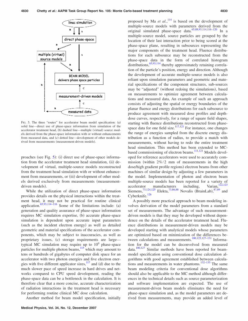
In an effort to quantify the speed and accuracy for thephantom component of the calculations by the various MCcodes being used for research and/or clinical planning pur-poses, Rogers and Mohan99 proposed what came to beknown as the ICCR benchmark. The tests and geometries forthe ICCR benchmark comparisons were as follows:99 !a"speed test: phantom of dimensions 30.5'30.5'30 cm with!5 mm"3 voxels filled either randomly with one of 4 materi-als !water, aluminum, lung, and graphite" or with wateralone, 6 MV photons !spectrum" from a point source at 100cm SSD and collimated to 10'10 cm2 at the phantom sur-face, !b" accuracy test: heterogeneous phantom as defined in!a" with 5'5'2 mm voxels !2 mm along the depth axis",18 MV photons !spectrum" from a point source at 100 cmSSD and collimated to 1.5'1.5 cm2 at the phantom surface.Beam spectra268 were provided for these comparisons in or-der to standardize the beam model used in the dose calcula-tions. Statistical uncertainties were to be reported as the rela-tive uncertainty in the dose for voxels with a dose greaterthan some arbitrary lower limit, such as 50% of the maxi-mum dose.99 Results for the ICCR benchmark are summa-rized in Table I. Some timing results have been added re-cently. Timing values have been scaled to that on a singleIntel P-IV 3.0 GHz processor.
The reader should be aware that the timing results re-ported in Table I are susceptible to large variations !on theorder of at least 20%" due to variations in compilers,memory size, cache, etc.99 Timing comparisons for moreclinically relevant treatment plans are presented in Sec.III E 4. These results have been reported by medical physi-cists using commercial MC systems for treatment planning.
III.B. Accelerator treatment head simulation
III.B.1. Sensitivity of simulations to electron beamand other parameters
In general one does not know all the details of the clinicalaccelerator. For example, the characteristics of the incidentelectron beam are only known approximately. Knowledge ofthe sensitivity of MC simulation results to input parameters,such as the position, direction, and energy of the initial elec-tron beam exiting the accelerator and to details of the geom-etry of the treatment head, is important. A sensitivity analysisis indispensable in determining which source and geometryparameters to adjust and by how much in order to improveagreement with user-specific measurements.
Factors influencing the characteristics of a photon beamare the energy, spatial, and angular distributions of the elec-trons incident on the target !or exiting the waveguide", and
4826 Chetty et al.: AAPM Task Group Report No. 105: Monte Carlo-based treatment planning 4826
Medical Physics, Vol. 34, No. 12, December 2007

the dimensions, materials, and densities of all the compo-nents interacting with the beam !the target, primary collima-tor, flattening filter!s", monitor chamber, collimating devices,such as blocks or MLCs, and beam modifying devices suchas wedges". Several investigators have reported on the sen-sitivity of megavoltage beam simulations to the electronbeam striking the target and other treatment headparameters.19,100–103 Faddegon et al.,19 in simulating Siemensaccelerators, showed that the key parameters are the meanenergy and focal spot size of the electron beam incident onthe exit window, the material composition and thickness pro-file of the exit window, target, flattening filter, primary col-limator, and the position of the primary collimator relative tothe target. Bieda et al.101 showed that the accelerator simu-lation for 20 MeV !Varian-produced" electron beams wasvery sensitive to the distance between the scattering foilsand, to a lesser extent, to the width of the shaped secondaryscattering foil. Changes to the primary or secondary foilthickness were found to significantly alter the falloff andbremsstrahlung components of the depth-dose curve.101
Sheikh-Bagheri and Rogers102 performed calculations of “in-air” off-axis ratios and depth-dose curves and comparedthese with measurements to derive estimates for the param-eters of the electron beam incident on the target, and to studythe effects of some mechanical parameters, such as targetwidth, primary collimator opening, flattening filter material,and density. Their study102 included several different photon
beam energies from accelerators produced by differentmanufacturers !Varian, Siemens, and Elekta". The electronbeam radial intensity distribution was found to influence theoff-axis ratios to a great extent. The greater the width of theelectron-beam radial intensity distribution, the relativelymore intense is the photon beam on the central axis.102 Fig-ure 3 shows the influence of the electron-on-target energyand radial intensity FWHM on 40'40 cm2 field profiledoses from Tzedakis et al.103 The calculated profiles are ob-served to be quite sensitive to these parameters. The centralaxis depth dose curves are also strongly influenced by theelectron-on-target energy.102 However, the central-axisdepth-dose curves are quite insensitive to variation in theradial intensity distribution of the electron beam striking thetarget, because the dose along the central axis is depositedprimarily by particles in the vicinity of the central axis. Thedivergence of the electron beam incident on the target alsoneeds to be considered as it may affect large field profiles.
Regarding the influence of individual treatment headcomponents, Sheikh–Bagheri and Rogers102 !see Table II"showed that even small changes !0.01 cm" in the primarycollimator’s upstream opening can affect in-air off-axis ratiosby restricting the number of bremsstrahlung photons contrib-uting to the scattered photon fluence reaching off-axis pointsdownstream. Dose profiles are quite sensitive to the compo-sition and density of the flattening filter as noted in Fig. 4,where two different flattening filter materials were used for
TABLE I. Summary of timing and accuracy results from the ICCR benchmark. Timing comparisons wereperformed using 6 MV photons, 10'10 cm2 field size, and those for the accuracy test, using 18 MV photonsand a 1.5'1.5 cm2 field size, as detailed in the ICCR benchmark !Ref. 99". All times have been scaled to thetime it would take running on a single, Pentium IV, 3 GHz processor. Readers should be aware that the timingresults, as well as the method used to scale the times, are subject to large uncertainties due to differences incompilers, memory size, cache size, etc.
Monte Carlo code Time estimate!min"
% mean difference relative to ESG4/PRESTA/DOSXYZ
ESG4/PRESTA/DOSXYZ 43 0, benchmark calculationVMC++ 0.9 ±1XVMC 1.1a ±1MCDOSE !modified ESG4/PRESTA" 1.6 ±1MCV !modified ESG4/PRESTA" 22 ±1DPM !modified DPM" 7.3b ±1MCNPX 60c Maximum difference of 8% at Al/lung interface
!on average ±1% agreement"PEREGRINE 43d ±1GEANT4 !4.6.1" 193e ±1 for homogeneous water and water/air interfaces
aResults not originally part of the ICCR benchmark study, from Ref. 76.bResults not originally part of the ICCR benchmark study, reported independently by author I.J.C. for themodified version of DPM developed for clinical planning calculations.cTiming results not originally part of the ICCR benchmark study, reported independently by author J.J.D.Calculations were performed using the *F8 !energy deposition" tally.dTiming and accuracy results not originally part of the ICCR benchmark study, reported independently byauthor D.S.-B.eTiming and accuracy results not originally part of the ICCR benchmark study. Estimated independently byauthor Seuntjens based on Poon and Verhaegen !Ref. 94" and ICCR type speed-test dose calculations !Ref. 270".Timing results are for the standard physics model; the low-energy and the PENELOPE model lead to a factor of2 more CPU time. The accuracy result reported is derived from the interface perturbation studies in Poon andVerhaegen !Ref. 94", applies to 1.25 MeV monoenergetic photon beams and represents the difference withEGSnrc using PRESTA-II electron step algorithm and “exact” boundary crossing. For a water/Pb interface and1.25 MeV photons, the maximum difference with EGSnrc increases to 6% !Ref. 94".
4827 Chetty et al.: AAPM Task Group Report No. 105: Monte Carlo-based treatment planning 4827
Medical Physics, Vol. 34, No. 12, December 2007

the calculations.102,104 The careful specification of the geom-etry and materials within the MC code is an important con-sideration. This includes verification of the input of the com-ponent geometric specifications, for example, by using thelisting files available with the BEAM !Ref. 23" system. More-over, for complicated components, such as the flattening fil-ter, independent attenuation calculations of these structures,using monoenergetic photons, may be helpful to verify theirthickness profiles.105,106 Attenuation of the photon beam bythe monitor ion chamber and the field mirror is negligibleand these structures are often omitted from MC simulationsof photon beams, except when backscatter to the monitor
chamber is being taken into account. The ion chamber andmirror are, however, potentially important structures in elec-tron beam simulations. The collimating jaws have no signifi-cant effect on the energy and angular photondistributions.14,107,108 Changing the composition of the sec-ondary collimators from pure tungsten to an alloy containing50% tungsten by weight does not significantly affect the cal-culated dose.102
Even in those cases for which the beam model includes anexplicit simulation of the accelerator head, end users of MCtreatment planning algorithms will probably have little con-trol over parameters affecting the treatment head simulation.It will be incumbent upon vendors to provide accurate beammodels !verified by measurements" for treatment planningpurposes. Vendors and developers should be aware of poten-tial difficulties associated with accurate specification of thetreatment head component structures. Such issues includedifficulty in obtaining proprietary information from accelera-tor manufacturers, incorrect proprietary information pro-vided by the manufacturers,101,102,104 undocumented accel-erator updates, and large uncertainties in importantparameters needed for accurate simulation, such as theelectron-on-target energy. Accelerator vendors are encour-aged to make accurate, detailed information of their accel-erators accessible in formats easy to implement in MC simu-lation, as established for instance by Siemens.109
III.B.2. Electron beam specifics
Simulation of the passage of electron beams through thetreatment heads of accelerators has figured prominently inMC radiotherapy calculations for many years. The first ap-plication of the BEAM code23 was to simulate electron beamsfor a wide range of accelerators. A variety of publicationshave demonstrated the accuracy of this technique for com-puting dose distributions and output ratios.24,110,111 Recentwork has established the methodology to achieve high accu-racy in matching calculated and measured dose distributionsfor even the largest fields, including asymmetries and thebremsstrahlung tail.112
The procedure for simulating the electron beam treatmenthead is quite similar to that of x rays. The components gen-erally important for electron beam therapy treatment headsimulations are shown in Table III. Photon beam componentsare also presented for comparison. For electrons, acceleratorsfrom the major vendors use a pair of scattering foils to flattenthe beam with minimal bremsstrahlung contamination. Alow-scatter monitor chamber may be employed and the mir-ror may be retracted from the beam. The jaw position isgenerally fixed for a given applicator and energy such thatthe relative output ratio depends only on the custom insert.
The critical parameters for electron beam simulation aredifferent than those for x rays. Sensitivity analyses providequantitative evidence of these differences.100,101,113 Due tothe sensitivity of the beam range to the primary electronenergy !a 0.2 MeV change in electron energy correspondswith a 1 mm change in beam range", the incident electronenergy is the primary tuning parameter for electron beam
FIG. 3. !a" The lateral dose-profile curves as a function of the FWHM of theradial intensity distribution for a monoenergetic, 6 MV, electron beam. Themeasured profile and five calculated dose profile curves are presented; eachcurve is normalized to the central axis. !b" The influence of electron energyon dose-profile curves. The energy was varied from monoenergetic 5.4 to6.6 MeV. For clarity only four calculated and measured profiles are pre-sented; each curve is normalized to the central axis. The FWHM of theradial intensity distribution was 0.3 cm FWHM in all cases. Reprinted fromTzedakis et al. !Ref. 103" with permission.
4828 Chetty et al.: AAPM Task Group Report No. 105: Monte Carlo-based treatment planning 4828
Medical Physics, Vol. 34, No. 12, December 2007

simulations. However, electron distributions are very sensi-tive to all the materials in the beam, especially the scatteringfoils and may also be affected by the monitor chamber if ithas thick walls. Hence, accurate geometric descriptions of allcomponents in the beam path are required for the simulationof electron beams. Asymmetries are evident in electron dose
distributions and parameters to adjust include angle of theincident beam and the lateral position of shaped scatteringfoils and the monitor chamber.
III.C. Modeling of the linear accelerator treatmenthead
III.C.1. General schemes
A beam model in the context of MC treatment planning isany algorithm that delivers the location, direction, and en-ergy of particles to the patient dose-calculating algorithm.The direct MC simulation of a beam is one form of a beammodel but for clarity we refer to it as a beam simulationrather than as a beam model. Accurate beam modeling is animportant prerequisite for accurate dose calculation withinthe patient. Beam models use one of three possible ap-
TABLE II. A summary of the findings of Sheikh-Bagheri and Rogers !Ref. 102".
Parameter in the linac model Impact on in-air off-axis factors Impact on central-axis depth dose values
Mean energy of the incident electron intensitydistribution !assumed Gaussian"
Decrease with increasing primary electron energy,e.g., !0.105±0.007 /MeV at 15 cm off-axis for aSiemens KD 6 MV beam. A 0.2 MeV mean energychange produces an observable effect.
A 0.2 MeV change in mean energycauses an observable change !2% or 3$with 0.7% or 1$ dose uncertainty".
Gaussian width of the incident electronenergy distribution
Show little or no dependence, e.g., widening of theFWHM from 0% to 20% resulted in no change, for aSiemens KD 6 MV beam. Asymmetrical energydistribution has a small effect, e.g., an asymmetricGaussian with 14% FWHM on the LHS of the peak and3% FWHM on the RHS of the peak causes a change of2% for a Siemens KD 18 MV beam.
Show weak dependence in the dosebuildup region and at large depths, e.g.,an asymmetric Gaussian with 14% FWHMon the LHS of the peak and 3% FWHMon the RHS of the peak increases buildupdose by up to 1.5% for a Siemens KD18 MV beam.
Gaussian width of the incident electron radialintensity distribution
Decrease quadratically with increasing Gaussianwidth, e.g., a change in FWHM from 0.01 to 0.15 cmleads to 7% decrease at 15 cm off-axis for a Varian 18MV beam.
Little or no observable effectconsidering statistical uncertainties.
Divergence of the incident electron beam!at a given intensity distribution FWHM"
Show little or no effect up to 0.5°; at 1° show adecrease of 1% at 15 cm off axis at 100 cm SSD, foran 18 MV Varian beam.
No observable effect up to a fewdegrees considering statistical uncertainties!1% or 1$".
Radius of the upstream opening of the primarycollimator
Sensitive to small changes, e.g., varying the upstreamopening by 0.01 cm produces a 1% change at 15 cmoff-axis for a Varian 18 MV beam.
No observable effect.
Density and material of the flattening filter Show strong dependence, e.g., reducing tungstendensity by 1 g cm!3 causes a 6% reduction at 15 cmoff axis for a Varian 15 MV beam. Using the incorrectmaterial has a very large effect, primarily because ofthe density change.
Not reported.
FIG. 4. MC calculated profiles in a water phantom !modified DPM, Univer-sity of Michigan/UMPlan" for a 15 MV !10'10 cm2" at 10 cm depth inwater. Input for the profile calculations were the phase space simulations ofthe Varian 21-EX treatment head, performed using BEAMnrc, with twodifferent material compositions specified for the flattening filter. Opencircles represent the MC profile with a copper flattening filter !)=8.933 g /cm3" and open triangles that with the tungsten filter !)=19.30 g /cm3". Ion chamber measurements are shown in the solid line.Calculations and measurements are each normalized to the central axis !Ref.104".
TABLE III. Components in the treatment head and other beam modifyingdevices for x ray and electron beams.
X rays Electrons
Exit window and target Exit window and primary scattering foilPrimary collimator Primary collimatorFlattening filter Secondary scattering foil may be presentMonitor chamber Monitor chamber !low scatter"Mirror MirrorAsymmetric jaws and MLC Jaw position fixed for each applicatorWedge, blocks, graticule Applicator with insertBolus Bolus, shielding on or below patient surface
4829 Chetty et al.: AAPM Task Group Report No. 105: Monte Carlo-based treatment planning 4829
Medical Physics, Vol. 34, No. 12, December 2007
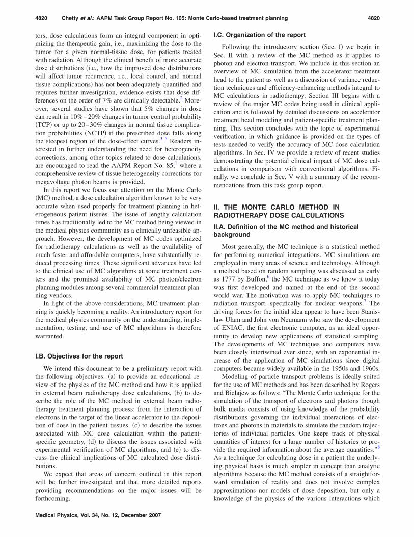
proaches !see Fig. 5": !i" direct use of phase-space informa-tion from the accelerator treatment head simulation, !ii" de-velopment of virtual, multiple-source models reconstructedfrom the treatment head simulation with or without enhance-ment from measurements, or !iii" development of other mod-els derived exclusively from measurements !measurement-driven models".
While the utilization of direct phase-space informationprovides details on the physical interactions within the treat-ment head, it may not be practical for routine clinicalapplication.65,93,114–116 Some of the limitations include: !a"generation and quality assurance of phase-space informationrequires MC simulation expertise, !b" accurate phase-spacesimulation is dependent upon accurate input parameters!such as the incident electron energy" as well as detailedgeometric and material specifications of the accelerator com-ponents, which may be subject to inaccuracies, as well asproprietary issues, !c" storage requirements are large—typical MC simulation may require up to 109 phase-spaceparticles for multiple photon beams,115 which may amount totens or hundreds of gigabytes of computer disk space for anaccelerator with two photon energies and five electron ener-gies with five different applicator sizes,117 and !d" due to themuch slower pace of speed increase in hard drives and net-works compared to CPU speed development, reading thephase-space data can be a bottleneck in the calculation. It istherefore clear that a more concise, accurate characterizationof radiation interactions in the treatment head is necessaryfor performing routine clinical MC dose calculation.
Another method for beam model specification, initially
proposed by Ma et al.,114 is based on the development ofmultiple-source models with parameters derived from theoriginal simulated phase-space data.65,88,93,114,116–120 In amultiple-source model, source particles are grouped by thelocation of their last interaction prior to being scored at thephase-space plane, resulting in subsources representing themajor components of the treatment head. Fluence distribu-tions for each subsource may be reconstructed from thephase-space data in the form of correlated histogramdistributions,65,93,114 thereby approximately retaining correla-tion of the particle’s position, energy and direction. Althoughthe development of accurate multiple-source models is alsoreliant upon simulation parameters and geometric and mate-rial specifications of the component structures, sub-sourcesmay be “adjusted” !without redoing the simulations", basedon measurements to optimize agreement between calcula-tions and measured data, An example of such an approachconsists of adjusting the spatial or energy boundaries of theplanar fluence and energy distributions for each subsource toproduce agreement with measured dose profiles and depth-dose curves, respectively, for a range of square field shapes,starting with fluence distributions reconstructed from phase-space data for one field size.117,121 For instance, one changesthe range of energies sampled from the discrete energy dis-tribution as a function of radius, to provide a match withmeasurements, without having to redo the entire treatmenthead simulation. This method has been extended to MC-based commissioning of electron beams.111,121 Models devel-oped for reference accelerators were used to accurately com-mission !within 2% /2 mm of measurements in the highdose/high gradient profile regions" electron beams from othermachines of similar design by adjusting a few parameters inthe model. Implementation of photon and electron beammultiple-source models has been reported for a variety ofaccelerator manufacturers including, Varian,122,123
Siemens,73,124,125 Elekta,73,86,88 Novalis !BrainLab",87,89 andCyberknife.126
A possibly more practical approach to beam modeling in-volves derivation of the model parameters from a standardset of measurements. The advantage of such measurement-driven models is that they may be developed without depen-dence on the details of the accelerator treatment head. Flu-ence distributions in measurement-driven models may bedeveloped starting with analytical models whose parametersare optimized based on minimization of the differences be-tween calculations and measurements.100,125,127–131 Informa-tion for the model can be deconvolved from measureddata.100,127 Similar methods have been reported for beam-model specification using conventional dose calculation al-gorithms with good agreement established between calcula-tions and measurements in water phantoms.132–135 The samebeam modeling criteria for conventional dose algorithmsshould also be applicable to the MC method although differ-ences in the technical details such as source parameterizationand software implementation are expected. The use ofmeasurement-driven beam models eliminates the need forphase-space simulation and, as the model parameters are de-rived from measurements, may provide an added level of
FIG. 5. The three “routes” for accelerator beam model specification: !a"solid line—direct use of phase-space information from simulation of theaccelerator treatment head, !b" dashed line—multiple !virtual" source mod-els derived from the phase-space information with or without enhancementsfrom measured data, and !c" dotted line—development of other models de-rived from measurements !measurement-driven models".
4830 Chetty et al.: AAPM Task Group Report No. 105: Monte Carlo-based treatment planning 4830
Medical Physics, Vol. 34, No. 12, December 2007

confidence in the accuracy of the model in homogeneousphantoms. Moreover, specification of beam models is similarto that with conventional dose algorithms, and does not re-quire expertise with MC accelerator simulation. However,rigorous verification of measurement-driven models in het-erogeneous phantoms is necessary to validate the !empiri-cally derived" fluence distributions. It has been shown that,in addition to the use of measurements in water phantoms,test cases in heterogeneous phantoms under conditions ofelectronic disequilibrium may be necessary to determine thecorrect energy spectrum unambiguously.136
III.C.2. Patient-specific beam modifiers
Transport through the patient-dependent components!such as the field-defining collimators and the MLC" may beclassified into one of the following three schemes, which wewill term: !a" explicit transport, !b" explicit-approximatetransport, and !c" pseudo-explicit transport. In an explicittransport scheme, all particles !with appropriate energy cut-off values" are transported using MC techniques through thecomponents; all details of the design geometry !such asrounded leaf ends, interleaf spacing, etc. for a MLC" shouldbe included in the geometry modeling.72,115,137 With explicit-approximate transport, approximations are employed in theMC photon/electron tracking scheme to improve the effi-ciency of the calculation.83,87,138,139 An example is the ap-proach of Siebers et al.,83 in which only first Compton scat-tered photons are transported through the MLC. The methodof Tyagi et al.139 includes simulation through the detailedMLC geometry accounting for all Compton scattered pho-tons, however, ignores the secondary electrons, i.e., assumesthey deposit their energies locally. In a pseudo-explicit trans-port scheme, beam fluence distributions are reconstructedfrom the phase-space simulation to develop subsources forcharacterizing components, such as the field definingjaws,93,120 electron applicators,114 and the MLC.88 Althoughthe need for time-intensive, explicit transport is obviatedwith the use of multiple subsources, the ability to incorporatedetailed geometric characteristics of components like theMLC may be difficult with this approach. Appropriatebenchmarking must be performed by developers and vendorsto evaluate the tradeoffs between speed and accuracy relatedto the use of various beam model approaches in MC-basedmodeling of patient-specific beam modifiers.
III.C.3. Output ratios
The output ratio !or relative output factor" is the ratio ofdose per monitor unit in a phantom for an arbitrary field sizeto that for a reference collimator setting, the latter usually10'10 cm2 at a SAD !or SSD" of 100 cm for a depth of 10cm for x-ray beams.140 Output ratios over the range of clini-cally useful field sizes are heavily influenced by the amountof head scattered radiation impinging on the phantom.140,141
Radiation generated by clinical accelerators can be charac-terized by a primary photon source generated through thebremsstrahlung process, and other extrafocal sources ac-counting for scattered photons arising primarily from the
flattening filter and primary collimator, typically 3%!8% ofthe energy fluence in a 10'10 cm2 field. The primarysource is a narrow sharp source normally a few millimetersin diameter, while the extrafocal sources tend to be muchbroader, more diffuse and bell-shaped in nature.142,143 Theoutput ratio is affected by the size and geometry of thesesources. The collimators !jaws and MLCs" block the extrafo-cal source when the field size is sufficiently small !*3'3 cm2" and for smaller fields the primary source startsbeing blocked by the collimators. The combination of ex-trafocal source and primary source cutoffs cause the outputratios to fall off sharply at small field sizes.143,144 Accuratesource modeling of small fields is especially important inIMRT planning where multiple, small field, off-axis seg-ments are often used.61,87,145 For medium sized fields !10'10 cm2–20'20 cm2", output ratios are more likely af-fected by the extrafocal sources as the collimators are largeenough to expose the entire primary source, however, smallenough to eclipse the extrafocal sources. In large fields, be-yond 20'20 cm2, the extrafocal sources are nearly com-pletely exposed—the increase in output ratios in these situa-tions is primarily a result of phantom scatter, lack ofbackscatter from the collimator jaws to the monitor chamber,and stray radiation from the treatment head.146,147 Dependingon the location of the jaws relative to the transmission cham-ber !which varies among the different linear acceleratortypes", radiation backscattered from the jaws into the cham-ber can also have an effect on the output ratios. Relative tolarge field sizes !40'40 cm2", backscattered radiation in-creases by 2%!3% at small field sizes !3'3 cm2" for 15MV photons on a Varian !21EX" linear accelerator, for ex-ample. Studies for photon beam MC algorithms have showncalculated output ratios to be within 1.5% of measurementsover a range of field sizes when accounting for backscatteredradiation.27,139,148,149 MC calculated electron beam output ra-tios !for field size-specific applicators" have also been re-ported to agree with measurements within 1%–2%.26,110
III.C.4. Dose buildup
There has been considerable discussion on discrepanciesbetween MC calculations and measurements in the dosebuildup region. Hartmann-Siantar et al.27 observed MC dosedeficits of up to 5 mm distance-to-agreement versus mea-surements and attributed these discrepancies to a source ofelectrons in the accelerator head not fully accounted for inthe treatment head simulation with BEAM. It has been shownthat arbitrarily increasing the electron contamination by asignificant amount removes the discrepancy.27,88,125 As theresult of further investigation, Ding150 concluded that the dis-crepancy could not be explained by the electron source hy-pothesis and postulated that contaminant neutrons emergingfrom the treatment head might be the cause. However, Dinget al.151 subsequently refuted this neutron hypothesis bymeasuring minimal neutron component in the dose buildupregion. Abdel-Rahman et al.,152 who performed MC calcula-tions !using EGSnrc" and a comprehensive set of measure-ments with multiple detectors, again found significant differ-
4831 Chetty et al.: AAPM Task Group Report No. 105: Monte Carlo-based treatment planning 4831
Medical Physics, Vol. 34, No. 12, December 2007
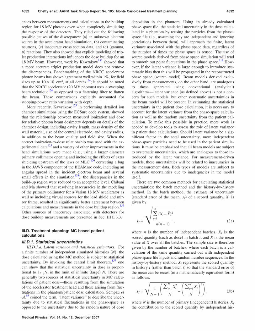
ences between measurements and calculations in the buildupregion for 18 MV photons even when completely simulatingthe response of the detectors. They ruled out the followingpossible causes of the discrepancy: !a" an unknown electronsource in the accelerator head simulation, !b" contaminatingneutrons, !c" inaccurate cross section data, and !d" !gamma,p" reactions. They also showed that explicit modeling of trip-let production interactions influences the dose buildup for an18 MV beam. However, work by Kawrakow153 showed thata more accurate triplet production model does not removethe discrepancies. Benchmarking of the NRCC acceleratorphoton beams has shown agreement well within 1%, for fieldsizes up to 10'10 cm2, at all depths154; it should be notedthat the NRCC accelerator !20 MV photons" uses a sweepingbeam technique154 as opposed to a flattening filter to flattenthe beam. These comparisons explicitly accounted forstopping-power ratio variation with depth.
More recently, Kawrakow,155 in performing detailed ionchamber simulations using the EGSnrc code system, showedthat the relationship between measured ionization and dosefor relative photon beam dosimetry depends on details of thechamber design, including cavity length, mass density of thewall material, size of the central electrode, and cavity radius,in addition to the beam quality and field size. When thecorrect ionization-to-dose relationship was used with the ex-perimental data155 and a variety of other improvements in thehead simulations were made !e.g., using a larger diameterprimary collimator opening and including the effects of extrashielding upstream of the jaws or MLC,156 correcting a bugin the JAWS component of the BEAMnrc code, including anangular spread in the incident electron beam and severalsmall effects in the simulation153", the discrepancies in thebuild-up region were reduced to an acceptable level. Chibaniand Ma showed that resolving inaccuracies in the modelingof the primary collimator for a Varian 18 MV accelerator aswell as including virtual sources for the lead shield and mir-ror frame, resulted in significantly better agreement betweencalculations and measurements in the dose buildup region.156
Other sources of inaccuracy associated with detectors fordose buildup measurements are presented in Sec. III E 3.3.
III.D. Treatment planning: MC-based patientcalculations
III.D.1. Statistical uncertaintiesIII.D.1.a. Latent variance and statistical estimators. For
a finite number of independent simulated histories !N", thedose calculated using the MC method is subject to statisticaluncertainty. By invoking the central limit theorem,157 onecan show that the statistical uncertainty in dose is propor-tional to 1 / &N, in the limit of infinite !large" N. There aregenerally two sources of statistical uncertainty in MC calcu-lations of patient dose—those resulting from the simulationof the accelerator treatment head and those arising from fluc-tuations in the phantom/patient dose calculation. Sempau etal.95 coined the term, “latent variance” to describe the uncer-tainty due to statistical fluctuations in the phase-space asopposed to the uncertainty due to the random nature of dose
deposition in the phantom. Using an already calculatedphase-space file, the statistical uncertainty in the dose calcu-lated in a phantom by reusing the particles from the phase-space file !i.e., assuming they are independent and ignoringcorrelations between them", will approach the finite, latentvariance associated with the phase space data, regardless ofthe number of times the phase space is reused. The use ofsource models derived from phase space simulation will tendto smooth out point fluctuations in the phase space.114 How-ever, if the latent variance is large enough to introduce sys-tematic bias then this will be propagated in the reconstructedphase space !source model". Beam models derived exclu-sively from measurements, on the other hand, are analogousto those generated using conventional !analytical"algorithms—latent variance !as defined above" is not a con-cern for such models, but other systematic uncertainties inthe beam model will be present. In estimating the statisticaluncertainty in the patient dose calculation, it is necessary toaccount for the latent variance from the phase-space calcula-tion as well as the random uncertainty from the patient cal-culation. To make this possible in practice, more work isneeded to develop tools to assess the role of latent variancein patient dose calculations. Should latent variance be a sig-nificant factor in the total uncertainty, more independentphase-space particles need to be used in the patient simula-tions. It must be emphasized that all beam models are subjectto systematic uncertainties, which are analogous to those in-troduced by the latent variance. For measurement-drivenmodels, these uncertainties will be related to inaccuracies inthe measurement data. Both types of models are subject tosystematic uncertainties due to inadequacies in the modelitself.
There are two common methods for calculating statisticaluncertainties: the batch method and the history-by-historymethod. In the batch method, the estimate of uncertainty!standard error of the mean, sx̄" of a scored quantity, X, isgiven by
sx̄ =&'
i=1
n
!Xi ! X̄"2
n!n ! 1", !3a"
where n is the number of independent batches, Xi is thescored quantity !such as dose" in batch i, and X̄ is the meanvalue of X over all the batches. The sample size is thereforegiven by the number of batches, where each batch is a cal-culation of the same quantity carried out with independentphase-space file inputs and random number sequences. In thehistory-by-history method, Xi represents the scored quantityin history i !rather than batch i" so that the standard error ofthe mean can be recast !in a mathematically equivalent form"as follows:
sx̄ =& 1N ! 1
('i=1
NXi
2
N! ('i=1
NXi
N)2) , !3b"
where N is the number of primary !independent" histories, Xithe contribution to the scored quantity by independent his-
4832 Chetty et al.: AAPM Task Group Report No. 105: Monte Carlo-based treatment planning 4832
Medical Physics, Vol. 34, No. 12, December 2007
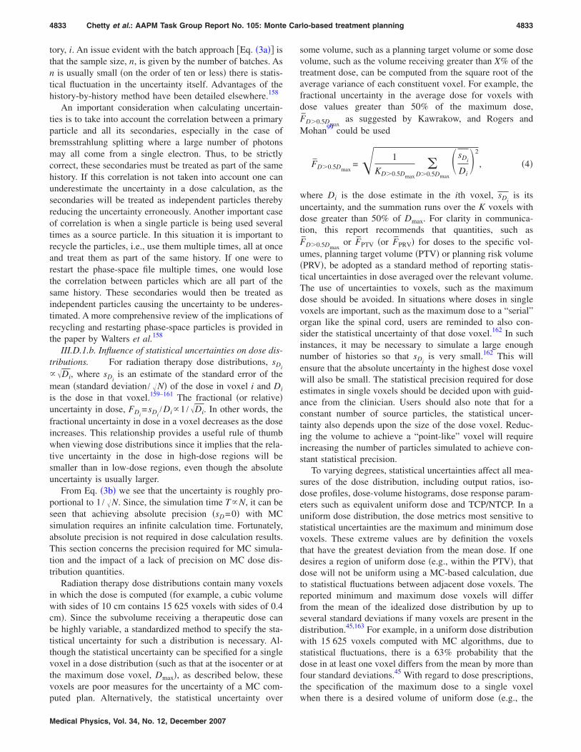
tory, i. An issue evident with the batch approach #Eq. !3a"$ isthat the sample size, n, is given by the number of batches. Asn is usually small !on the order of ten or less" there is statis-tical fluctuation in the uncertainty itself. Advantages of thehistory-by-history method have been detailed elsewhere.158
An important consideration when calculating uncertain-ties is to take into account the correlation between a primaryparticle and all its secondaries, especially in the case ofbremsstrahlung splitting where a large number of photonsmay all come from a single electron. Thus, to be strictlycorrect, these secondaries must be treated as part of the samehistory. If this correlation is not taken into account one canunderestimate the uncertainty in a dose calculation, as thesecondaries will be treated as independent particles therebyreducing the uncertainty erroneously. Another important caseof correlation is when a single particle is being used severaltimes as a source particle. In this situation it is important torecycle the particles, i.e., use them multiple times, all at onceand treat them as part of the same history. If one were torestart the phase-space file multiple times, one would losethe correlation between particles which are all part of thesame history. These secondaries would then be treated asindependent particles causing the uncertainty to be underes-timated. A more comprehensive review of the implications ofrecycling and restarting phase-space particles is provided inthe paper by Walters et al.158
III.D.1.b. Influence of statistical uncertainties on dose dis-tributions. For radiation therapy dose distributions, sDi+&Di, where sDi
is an estimate of the standard error of themean !standard deviation / &N" of the dose in voxel i and Diis the dose in that voxel.159–161 The fractional !or relative"uncertainty in dose, FDi
=sDi/Di+1 /&Di. In other words, the
fractional uncertainty in dose in a voxel decreases as the doseincreases. This relationship provides a useful rule of thumbwhen viewing dose distributions since it implies that the rela-tive uncertainty in the dose in high-dose regions will besmaller than in low-dose regions, even though the absoluteuncertainty is usually larger.
From Eq. !3b" we see that the uncertainty is roughly pro-portional to 1 / &N. Since, the simulation time T+N, it can beseen that achieving absolute precision !sD=0" with MCsimulation requires an infinite calculation time. Fortunately,absolute precision is not required in dose calculation results.This section concerns the precision required for MC simula-tion and the impact of a lack of precision on MC dose dis-tribution quantities.
Radiation therapy dose distributions contain many voxelsin which the dose is computed !for example, a cubic volumewith sides of 10 cm contains 15 625 voxels with sides of 0.4cm". Since the subvolume receiving a therapeutic dose canbe highly variable, a standardized method to specify the sta-tistical uncertainty for such a distribution is necessary. Al-though the statistical uncertainty can be specified for a singlevoxel in a dose distribution !such as that at the isocenter or atthe maximum dose voxel, Dmax", as described below, thesevoxels are poor measures for the uncertainty of a MC com-puted plan. Alternatively, the statistical uncertainty over
some volume, such as a planning target volume or some dosevolume, such as the volume receiving greater than X% of thetreatment dose, can be computed from the square root of theaverage variance of each constituent voxel. For example, thefractional uncertainty in the average dose for voxels withdose values greater than 50% of the maximum dose,F̄D,0.5Dmax
as suggested by Kawrakow, and Rogers andMohan99 could be used
F̄D,0.5Dmax=& 1
KD,0.5Dmax
'D,0.5Dmax
( sDi
Di)2
, !4"
where Di is the dose estimate in the ith voxel, sDiis its
uncertainty, and the summation runs over the K voxels withdose greater than 50% of Dmax. For clarity in communica-tion, this report recommends that quantities, such asF̄D,0.5Dmax
or F̄PTV !or F̄PRV" for doses to the specific vol-umes, planning target volume !PTV" or planning risk volume!PRV", be adopted as a standard method of reporting statis-tical uncertainties in dose averaged over the relevant volume.The use of uncertainties to voxels, such as the maximumdose should be avoided. In situations where doses in singlevoxels are important, such as the maximum dose to a “serial”organ like the spinal cord, users are reminded to also con-sider the statistical uncertainty of that dose voxel.162 In suchinstances, it may be necessary to simulate a large enoughnumber of histories so that sDi
is very small.162 This willensure that the absolute uncertainty in the highest dose voxelwill also be small. The statistical precision required for doseestimates in single voxels should be decided upon with guid-ance from the clinician. Users should also note that for aconstant number of source particles, the statistical uncer-tainty also depends upon the size of the dose voxel. Reduc-ing the volume to achieve a “point-like” voxel will requireincreasing the number of particles simulated to achieve con-stant statistical precision.
To varying degrees, statistical uncertainties affect all mea-sures of the dose distribution, including output ratios, iso-dose profiles, dose-volume histograms, dose response param-eters such as equivalent uniform dose and TCP/NTCP. In auniform dose distribution, the dose metrics most sensitive tostatistical uncertainties are the maximum and minimum dosevoxels. These extreme values are by definition the voxelsthat have the greatest deviation from the mean dose. If onedesires a region of uniform dose !e.g., within the PTV", thatdose will not be uniform using a MC-based calculation, dueto statistical fluctuations between adjacent dose voxels. Thereported minimum and maximum dose voxels will differfrom the mean of the idealized dose distribution by up toseveral standard deviations if many voxels are present in thedistribution.45,163 For example, in a uniform dose distributionwith 15 625 voxels computed with MC algorithms, due tostatistical fluctuations, there is a 63% probability that thedose in at least one voxel differs from the mean by more thanfour standard deviations.45 With regard to dose prescriptions,the specification of the maximum dose to a single voxelwhen there is a desired volume of uniform dose !e.g., the
4833 Chetty et al.: AAPM Task Group Report No. 105: Monte Carlo-based treatment planning 4833
Medical Physics, Vol. 34, No. 12, December 2007

PTV", will result in an underdosage to this volume. Simi-larly, dose prescription to the minimum dose voxel will resultin an overdose to the relevant volume. Isodose contours arealso sensitive to statistical noise. For well-defined fields,such as rectangular fields used in beam commissioning, even1% !1s" statistical uncertainty causes observable jitter in iso-dose contours. For patient fields that have irregular shapes,the acceptable amount of statistical uncertainty for isodoseviewing is a matter of personal preference and should beagreed upon by the planner and the physician. It has beensuggested that 2% statistical uncertainty on the Dmax voxel isadequate for isodose evaluation.160 When viewing statisticaljitter in MC isodose distributions, the physicist should re-mind observers that overall dose delivery accuracy is limitedto within a few percent; therefore there is uncertainty in theactual location of an isodose surface even when dose is com-puted with non-MC algorithms. From this point of view, theplanning team can use MC isodose jitter as a mechanism toopen the dialog on realistic dose uncertainty in actual treat-ment delivery.
Integrated dose quantities, such as dose volume histo-grams !DVHs" are less sensitive to statisticaluncertainty.159–165 DVHs computed with the MC method rep-resent the actual DVH !that computed with a hypothetical0% statistical uncertainty simulation", convolved with a sta-tistical uncertainty distribution. With this realization, Sem-pau and Bielajew159 and Jiang et al.165 reported that the ef-fect of the “statistical noise” on DVHs could be removed bydeconvolving the uncertainty from the DVH, allowing sub-stantial decrease in the required number of histories used,depending on the complexity of the DVH. In general, theblurring effect due to statistical noise is greatest for steepDVHs, such as those for PTVs, while shallow DVHs, such asthose for critical structures are less affected.
The sensitivity of quantities such as TCP and NTCP tostatistical noise depends upon the parameters used by themodel164 and on the magnitude of the noise. Kawrakow161
has shown for general dose-based cost functions that the un-certainty in the cost function decreases more rapidly than theindividual dose uncertainties when the plan is close to opti-mum as expressed by the cost function. This implies thatduring IMRT optimization, where plan updates are basedupon evaluation of such cost functions, larger statistical un-certainty might be acceptable.
A method to reduce the effect of statistical uncertainties inMC dose distributions is to postprocess the dose distribution.These methods have been termed denoising or smoothingtechniques. Various methods related to digital filtering,166,167
wavelet thresholding,168,169 adaptive anisotropic diffusion,170
and denoising based on a minimization problem171 have beenproposed. A detailed comparison of these methods is pre-sented in the article by El Naqa et al.172 Denoising is anapproximate, efficiency enhancing method !i.e., it is not avariance reduction technique" since it can introduce system-atic bias into the calculation. Nonetheless, denoising tech-niques are useful as they can reduce the overall !systematic+random" uncertainty when the random component de-
creases more than the systematic component increases.Kawrakow presented a series of tests to evaluate the suitabil-ity of MC dose distribution denoising algorithms.167 Thesetests are based on the fact that one can determine the “cor-rect” dose distribution by simulating many histories !for avery high precision" and then comparing the denoised distri-bution from a simulation with a much smaller number ofhistories to the high precision results. The tests include:
• visual inspection of isodose contours,• evaluating root-mean-square difference between dose
distributions,• evaluating the maximum dose difference,• comparisons of dose-volume histograms with and with-
out denoising, and• comparing the fraction of voxels failing an x% /y mm
test.
Denoising methods reduce the number of particles !and,hence, the calculation time" required to achieve a given un-certainty by a factor of 3–10. Denoising techniques requireproper validation under the full range of clinical circum-stances before they are used with MC dose algorithms.
III.D.2. Dose prescriptions and monitor unitcalculation
The stochastic nature of the MC method raises questionsfor prescribing dose. It is common clinical practice to pre-scribe dose to a single voxel or to base the dose prescriptionon the maximum or minimum dose voxels. However, as dis-cussed above !Sec. III D 1.2", in an approximately uniformdose distribution, the outliers !the maximum and minimumdose voxels" are subject to the largest statistical fluctuationand even other single voxel doses may lack the precision formonitor unit calculations. Standard treatment planning analy-sis methods using isodose distributions and dose-volume his-tograms rely on dose averaged over a volume. It is logical toextend this practice to the prescription of dose, therebyavoiding precision issues in doses calculated in small vol-umes. For example, dose may be prescribed to an isodosesurface, to a region of uniform dose !averaged over manyvoxels" about the isocenter, or to a single point on a dosevolume histogram. The practice is emerging to calibrate thecalculated dose distribution by performing a calculation inthe standard geometry where the accelerator is set to delivera given dose per monitor unit, !e.g., 1 cGy/MU" at a givenvoxel. In this case, the dose at the calibration point may becalculated to high precision by averaging over a large num-ber of voxels in a uniform dose region.
The issue of monitor unit calculations to specific singlevoxels within the target volume !e.g., the isocenter" for rou-tine clinical planning may be confounded by large statisticalfluctuations in the doses to individual voxels. Although thetreatment planning practice is quickly moving towardvolume-based dose prescriptions, particularly for IMRT plan-ning, the ability to perform second MU checks for plan veri-fication purposes is an important component of the standardpractice. Until more efficient solutions are available, MU cal-
4834 Chetty et al.: AAPM Task Group Report No. 105: Monte Carlo-based treatment planning 4834
Medical Physics, Vol. 34, No. 12, December 2007

culations based on single-voxel-dose prescriptions should beperformed with very high precision. That said, this taskgroup encourages a shift in paradigm from point-based to-ward volume-based dose prescriptions, which we feel willsoon become the standard method for prescribing doses inradiotherapy planning. The task group strongly discouragesvendors from using the Dmax or Dmin dose voxels or othersingle voxel doses for dose prescription and monitor unitcalculations in their MC-based treatment planning systems.Current users of MC algorithms are encouraged to find waysof circumventing point-based dose prescriptions if their sys-tems are not flexible enough to allow otherwise. To obviatethe concerns of dose prescription based on a single voxel,one institution !author J.E.C., Ottawa Hospital" has devel-oped the following “work around” method for MC-basedelectron beam calculations: A dose distribution is calculatedusing 100 MU; this dose distribution in absolute terms isequivalent to a relative isodose distribution normalized to thestandard calibration conditions !10'10 applicator, 100 cmSSD, dmax depth". For dose prescription, the physicianchooses the isodose line that encompasses the target. Thedose prescription point is then positioned on this isodose linealong the central axis of the beam, and the treatment MUsare determined. A second calculation is performed as a checkof the MUs and the final dose distribution.
For multiple 3D-CRT or IMRT fields, the procedure forgenerating monitor units is similar to that for single fields.For example, a given isodose line !such as the 95% line" canbe selected for dose prescription and, for a given field, thedose contribution to a single voxel !e.g., the projected fieldcax point" along this line is determined from the treatmentplan. For a calibrated MC algorithm, the absolute dose con-tribution from the given field in this voxel !on the selectedisodose line" will be computed in units of cGy/MU, fromwhich the monitor units for the beam can be calculated. Acomplete formalism for MU calculations for the differenttypes of treatment deliveries has been provided by Ma etal.173
III.D.3. CT-to-material conversions
For conventional algorithms, electron densities extractedfrom the CT image are used to scale the influence of primaryand, ideally, also secondary radiation interactions. MC algo-rithms utilize material density and the material atomic com-position when performing particle transport. The differingatomic compositions of patient materials !e.g., soft tissue,bone, lung, air" result in different cross sections for the vari-ous radiation interactions. While material compositions can-not be determined solely from a single energy CT, they canbe indirectly approximated by estimating the mass densityfrom the electron density followed by assigning a material toeach voxel.37,86,174–176 For some MC codes, explicit materialspecification is circumvented by directly relating the CT#Hounsfield !HU"$ numbers to material interaction coeffi-cients, based upon parameterization of materials representa-tive of the patient,37 for example those tabulated in ICRUReport No. 46.177
To ensure proper correspondence between HU and mate-rials !or material interaction coefficients", correspondencebetween these quantities must be established during the CTand treatment planning system commissioning process. Toensure appropriate material specifications, it may be desir-able to have several conversion tables, whose selection isbased upon knowledge of the particular patient’s character-istics. Use of multiple calibration curves reduces the volumeof inappropriate tissues specified in given regions, such aslung tissue within a prostate gland, however. Although theimportance of exact material specification has been estab-lished in other studies,178 more work in this area of researchrelevant to clinical treatment planning is necessary. Otherinformation about the patient may also be helpful. For ex-ample, in a patient with a hip implant, it may be impossibleto distinguish if the implant is titanium, steel, or a compositebased solely on the CT numbers. In this case, material as-signment based on knowledge of the material implanted inthe patient would be beneficial. A recent evaluation of theinfluence of material compositions on dose distributions178
showed dose errors of up to 10% for 6 and 15 MV photons,and 30% for 18 MeV electrons due to media and/or massdensity misassignment, when comparing dose distributionsbetween a known phantom and a CT-imaged phantom withcompositions and densities assigned by a conversion process.The use of conversion techniques based purely on mass den-sity !e.g., assuming the only patient material is water, butwith varying density", as employed in conventional algo-rithms, is discouraged with MC simulation because most ofthese methods ignore dependencies of particle interactionson the materials, which can lead to notable discrepancies inhigh atomic number materials.176
CT number artifacts caused by issues such as beam hard-ening in the CT scanning process or by high density struc-tures, such as dental fillings are potentially important in MCdose calculation. Other artifacts may arise, for example,when the CT scanner encounters a sharp edge, such as thesurface of a rectangular solid phantom, where a blurred edgemay result after image reconstruction. In one observed case,the resultant contour showed 3 mm of additional phantom,causing the MC-calculated percentage depth dose curves tobe shifted 3 mm toward the surface.269 Such issues are ofrelevance to both MC- and non-MC-based algorithms andwill need to be taken into consideration in order to performaccurate dose calculations in the dose buildup region.
As with any dose algorithm, testing should be performedto evaluate the effect of artifacts on the accuracy of the MCdose calculation.179,180 It must be emphasized that the accu-racy of CT-number to material conversions affects all dosecalculation algorithms, both MC- and non-MC-based meth-ods.
III.D.4. Dose-to-water and dose-to-medium
Historically, radiotherapy dose measurements and calcu-lations have been performed in, or specified in terms of theabsorbed dose to water !Dw". With MC-based algorithms,
4835 Chetty et al.: AAPM Task Group Report No. 105: Monte Carlo-based treatment planning 4835
Medical Physics, Vol. 34, No. 12, December 2007

particle transport simulations occur in materials representa-tive of patient media; dose is therefore specified to the pa-tient medium !Dm". For tissues with densities near1.0 g /cm3, the difference between Dw and Dm for megavolt-age photon beams is small !1%!2%", however, for higherdensity materials, such as cortical bone, the difference can beas large as 15%,176 since the stopping powers of water andthese higher-density materials differ more significantly.Therefore, there is a systematic difference between the dosecomputed using conventional analytical algorithms and MC
simulation. Figure 6 shows the dose and DVH differencesbetween plans calculated with Dw and Dm for a typical headand neck IMRT treatment plan.181
To use MC simulation in the current clinical practice so asto be able to compare Dm with historical Dw results, requiresa conversion of Dm to Dw for dose prescriptions, isodosecoverage, dose-volume histograms, and any other dose re-lated metrics. In this context, the converted Dw represents thedose to a small volume of water embedded in the actualmedium. Whether one should eventually use Dm in place of
FIG. 6. MC-based !MCV system" dose-to-medium !Dm"and dose-to-water !Dw" results for a typical head andneck IMRT treatment plan: !a" Dm, !b" Dw, and !c"DVH comparison. Reprinted from Dogan et al. !Ref.181" with permission.
4836 Chetty et al.: AAPM Task Group Report No. 105: Monte Carlo-based treatment planning 4836
Medical Physics, Vol. 34, No. 12, December 2007

Dw directly in clinical prescriptions remains the subject ofdebate.182 Arguments in favor of using Dw for dose specifi-cations include:
• Historical clinical experience has been derived based onDw, hence, Dw allows direct compliance with previousclinical experience and with conventional dose algo-rithms. Doses reported in clinical trials are based on Dw,hence, therapeutic and normal tissue tolerance doses arebased on Dw.
• Accelerator and ionization chamber calibration proto-cols are Dw based.
• Tumor cells embedded within a medium are morewater-like than medium-like, e.g., a tumor cell embed-ded in a bone matrix.
Arguments in favor of using Dm for dose specificationinclude:
• Dm !or the dose to the tissues of interest" is the quantityinherently computed by MC dose algorithms. This maybe of more clinical relevance than the doses on whichhistorical clinical experience is based, which are ap-proximate estimates of the true dose in the first place.
• Converting Dm back to Dw may involve additional com-plexity and introduce additional dose uncertainty.
• The difference between Dm and Dw for tissue equivalentmaterials is rather small and is likely to have minimalimpact in clinical practice.
• It is known that, due to organ and target motion, thedose actually delivered in the course of a treatment maybe significantly different from the planned dose. Con-version of Monte Carlo computed doses to Dw mayanalogously necessitate discussions on conversion to“dose to a static patient,” should 4D planning and de-livery techniques become routinely used in the clinic.183
The conversion of Dm to Dw or vice versa requires anapplication of Bragg–Gray cavity theory: Dw=Dm!S̄ /)"m
w,where !S̄ /)"m
w is the unrestricted water-to-medium mass col-lision stopping power averaged over the energy spectra ofprimary electrons at the point of interest. One method toaccomplish this conversion176 is to utilize the fact that forpatient-like materials, !S̄ /)"m
w is approximately invariantthroughout a photon radiation therapy field !within 1%",hence, !S̄ /)"m
w can be used as a post-processing step to con-vert Dm to Dw. However, this requires that a sufficient num-ber of materials be specified so that the material-dependentdose conversion approximates a continuous function.184
Rather than postprocessing the dose conversion, one canmultiply the energy deposited by primary and secondaryelectrons on each electron energy-loss step by the factor!L /)"m
w, the ratio of the restricted mass collision stoppingpowers of water to local medium for the current energy ofthe electron. This is done in the MC transport code, therebydirectly obtaining Dw. Alternatively, material interaction datamay be evaluated over continuously parameterized spacewith cross sections and stopping powers for specific materi-als scaled relative to water.35,37 Figure 7 shows a parameter-
ization of the mass collision stopping power as a function oftissue density for different electron beam energies.37 The fitis shown to be in good agreement with ICRU data177 forbody tissues. The advantage of this approach is that it cir-cumvents the potential misassignment of media at materialboundaries37 which arises when the human tissue mass den-sity range is divided into bins representing different tissues,especially when the number of material bins is small.184
Until further studies indicate clinical justification for se-lecting Dm or Dw, it is the consensus of this task group thatMC dose results should: !a" explicitly indicate the material towhich the dose is computed and !b" allow conversion be-tween Dm and Dw using one of the methods discussed above,or other methods as developed in future investigations.
III.D.5. IMRT dose calculation and optimization
A strength of the MC method is its ability to accuratelycompute dose for complex dose delivery scenarios such asencountered in IMRT. IMRT often involves large intensitygradients and is usually delivered using a sequence of smallstatic or dynamically shaped MLC segments. Under thesecircumstances, the assumptions used in conventional algo-rithms regarding scatter equilibrium and output ratio varia-tion with field size often break down.185 Additionally, inIMRT a significant fraction of dose to structures of interest!particularly dose limiting critical structures" is due to radia-tion scattered from or transmitted through the MLC.186 MCsimulation circumvents these limitations since it makes noassumptions regarding radiation equilibrium and can trans-port particles through the detailed MLC leafgeometry87,137,187 to include MLC leakage radiation, even fordynamic MLC leaf sequences.138,188,189
FIG. 7. Mass collision stopping power divided by the mass collision stop-ping power of water as a function of density normalized to water. A com-parison of the fit function to the ICRU data !Ref. 177" for body tissues forelectron energies of 5, 15, and 30 MeV is shown. The few points outside thecurve are materials like urinary stones, which are considered to have negli-gible effects. Reprinted from Kawrakow et al. !Ref. 37" with permission.
4837 Chetty et al.: AAPM Task Group Report No. 105: Monte Carlo-based treatment planning 4837
Medical Physics, Vol. 34, No. 12, December 2007

In using MC calculation in IMRT, a consideration is themethod used to incorporate the MLC into the dose calcula-tion. Intensity modulation has been incorporated into MCsimulation using the conventional planning system’s inten-sity matrix,190 independently generated fluence modificationmatrices,87,92,191,192 or direct transport through the MLC.61,189
Note that errors introduced by fluence approximations usedduring the MC dose calculation will be propagated throughto the prediction of the patient’s dose. Thus, when a fluencematrix approach is used for MC dose calculations, differ-ences with respect to a conventional algorithm’s heterogene-ity correction will be detected, but fluence prediction errorsmay go undetected, particularly if the same fluence matrix isused both for the conventional and MC calculations. How-ever, when MC simulation is used to transport directlythrough the detailed MLC geometry, these fluence errorsshould be detected. Accounting for geometric details in theMLC geometry, such as interleaf leakage is possible using afluence matrix approach, however, will require a very highresolution calculation matrix, which may be a limiting factor.Moreover, the energies of the scattered particles through theMLC using such an approach will be approximate. Whetheror not modeling the intricate details of the MLC !versusmore approximate fluence matrix approaches" will lead toclinically significant differences in IMRT treatment planningis not a fully resolved issue. More treatment planning studiesin this area of research are necessary to better understand theassociated clinical implications.
Application of the MC method for IMRT QA has beendemonstrated by several research groups61,87,139,190,192–194 us-ing MC simulation to recompute dose distributions opti-mized with the conventional dose planning algorithm. Whenusing MC calculations as the reference plan and ignoringstatistical fluctuations, dose differences between conven-tional and MC algorithms can be considered systematic.195
Ma et al.191 found dose errors in excess of 5% and 20%!relative to the prescribed dose" in targets and critical struc-tures respectively due to patient heterogeneities, in compar-ing MC calculations !employing an independent fluence ma-trix" with a pencil-beam model. In comparing MCcalculations with a conventional planning system’s !pencil-beam model" intensity matrix for head and neck and lungcases, Wang et al.190 found a 20% lower V95 !volume receiv-ing at least 95% of the target dose" for a lung plan, and a 9%lower D95 !dose delivered to at least 95% of the target vol-ume" for a head and neck plan. Average agreement among allhead/neck and lung cases in this study, however, was quitegood.190 Regarding the transport of particles through theMLC, Siebers and Mohan61 showed fluence-based IMRTdose underestimates of 4.5% in V95 and heterogeneity-baseddose overestimates of 5% in V15 in the same treatment plan.In intercomparing MC codes, Reynaert et al.196 reported de-viations of up to 10% in DVHs between PEREGRINE andBEAMnrc calculations. These discrepancies were attributedto differences in modeling of the Elekta !SLi-plus" MLC, notcaused by the particle transport in the patient. This studyfurther illustrates the importance of careful modeling of thedetails of the MLC in IMRT treatment planning.
MC-based IMRT plan optimization is limited by the clini-cal availability of MC calculation as a whole and the largecalculation time required to perform the multiple IMRT dosecalculations required for optimization. MC simulation duringoptimization allows the optimizer to account for heterogene-ity induced dose perturbations, as well as for MLC leakageand scattered radiation. Inaccurate dose algorithms used dur-ing optimization can result in convergence errors195 in whichthe optimized fluence pattern differs from that correspondingto the optimal dose distribution.
Studies demonstrating the use of the MC method in IMRToptimization include the work of Laub et al.,197 who utilizeda MC algorithm to evaluate the cost function during optimi-zation but a pencil beam to compute the cost function deriva-tives used by the optimizer. Jeraj et al.,195 reported on con-vergence and systematic errors in the IMRT inverse planningprocess !for lung cancer" resulting from the use ofconvolution/superposition and pencil beam algorithms, ver-sus the Monte Carlo method. A similar study for treatmentplanning of head and neck cancers was published by Doganet al.198 Another study by Siebers et al.199 demonstrated theuse of correction-based schemes to produce convergence ofdoses computed by conventional algorithms with MC calcu-lations. Bergman et al.200 reported on the use of an EGSnrc-based MC beamlet dose distribution matrix for IMRT plan-ning using a direct aperture optimization algorithm. The goalof their work was to assess the improvement in accuracyover conventional algorithms in using MC methods for boththe final dose calculation as well as in the inverse planningprocess.200 Combining these methods with statistical smooth-ing and denoising techniques,166–172 after comprehensivebenchmarking, may allow introduction of MC-based IMRToptimization into routine clinical practice, particularly sinceit has been shown that cost functions converge faster thanindividual dose uncertainties.161 For a review of other stud-ies, the reader is referred to the article by Verhaegen andSeuntjens.25
III.D.6. Voxel size effects
As is the case with any dose calculation algorithm, calcu-lated dose is affected by the size of the scoring voxel. ForMC calculations, typical values in the scoring dimension arevoxel sides of 2–5 mm for field sizes greater than 3'3 cm2 and 1–2 mm for field sizes less than 3'3 cm2. Forcalculations where geometric details of the MLC are in-cluded in the modeling, scoring voxel sizes no larger than1–2 mm will be necessary to diminish volume averaging ofdose from inter- and intraleaf leakage. As with conventionalalgorithms, MC-based IMRT calculations should be per-formed using voxel sizes of 2–3 mm or less in the highgradient regions.201,202 In addition to affecting the spatialresolution, the statistical uncertainty will be influenced bythe voxel size; reducing the voxel size will increase the rela-tive uncertainty for a fixed number of source particles be-cause fewer particles deposit dose in the smaller volume.Increasing the voxel size !and, hence, volume" will reducethe relative uncertainty but may introduce errors due to re-
4838 Chetty et al.: AAPM Task Group Report No. 105: Monte Carlo-based treatment planning 4838
Medical Physics, Vol. 34, No. 12, December 2007

duced spatial resolution. An example of the influence ofvolume-averaging effects resulting from the use of largervoxel sizes !*0.5 cm on each side" in MC electron calcula-tions is discussed in Sec. III E 3.5.
III.D.7. Cross sections
The uncertainties in photon interaction cross section datain the energy range from 5 keV to a few MeV is of the orderof 1%!2%.203 Although many MC codes use the incoherent-scattering-factor approximation !which assumes scattering ofphotons from stationary, free electrons", this approximationis found to be accurate in the mega-voltage energy regime,where the energy of the incident photon is much higher thanthat of the electron K-shell binding energy.204 An excellentreview of the cross sections for bremsstrahlung productionand electron-impact ionization has been provided bySeltzer.205 It is shown that, in general, calculated cross sec-tions for the various electron interaction processes are inagreement with measurements within the combined experi-mental and theoretical uncertainties.205 It is felt that crosssection and electron data in the megavoltage energy rangeare sufficiently accurate,206 assuming that sampling of thesecross sections is done accurately within a given code. Thesesame effects will be present in doses computed with theconvolution/superposition algorithm.
III.E. Experimental verification
III.E.1. Introduction
In this report experimental verification of the MC algo-rithm deals with how accurately the algorithm performs un-der different test conditions within a phantom. As with anyalgorithm, verification and testing is a necessary step to en-sure safety of use in the clinical setting. It is the consensus ofthis task group that verification of a MC algorithm should besimilar to that of any model-based dose calculation algo-rithm, such as convolution/superposition. The clinical com-missioning and acceptance testing of dose calculation algo-rithms has been reported.48–50 Additional testing to confirmthe accuracy of the MC algorithm in situations of electronicdisequilibrium will be helpful. Quantification of benchmarkcases !such as the ICCR benchmark99" should be performedby either the user, or the vendor. The intent of this section isto provide some examples of additional types of testing thatmay be included to assure the accuracy of the MC algorithm.The specification of required measurements for acceptancetesting and commissioning of the MC algorithm and the cri-teria for algorithmic agreement with measurements is beyondthe scope of this report.
III.E.2. Previous work
Toward the goal of verification of dose calculation algo-rithms, there have been a variety of studies related to mea-surements in heterogeneous media. These investigations !see,for example, Refs. 207–212" have usually focused on estab-lishing limitations of conventional dose algorithms in hetero-geneous media and on how the use of physics-based algo-
rithms, such as the convolution and MC methods, can beused to produce more accurate results. More recently, Arn-field et al.213 found large differences !up to 10%" betweencollapsed cone convolution and MC !PEREGRINE" calcula-tions in an 8 cm lung-equivalent slab embedded within solidwater and irradiated by a 4'4 cm2, 18 MV photon beam.Their work included film and ion chamber detectors andshowed that MC calculations were in good agreement withmeasurements.213
With respect to patient planning, studies91,115,214–219 havepointed out major differences between MC calculation andconventional methods, such as the 3D pencil beam andconvolution/superposition algorithms. Over the past tenyears, there has been a growing interest in the use of the MCmethod in clinical treatment applications with many institu-tions around the world actively involved in the developmentand testing of such systems. Many experiments in homoge-neous and heterogeneousphantoms26,27,71,75,82,84,86,93,96,115,119,194,213,220–225 have beendirected toward verification of MC algorithms for clinicalplanning applications. The interested reader is referred tothese and other related publications for a comprehensive re-view of the various types of experimental testing of MCtreatment planning algorithms.
III.E.3. Types of verification experiments
Experimental verification of a MC algorithm should in-clude testing to assess the accuracy of: !a" the beam model!be it measurement-driven or based on treatment head simu-lation" and !b" the radiation transport algorithm in homoge-neous and heterogeneous phantoms. The former is part ofroutine commissioning of dose calculation algorithms,whereas the latter is likely to have significantly more in-volvement from developers and vendors.
III.E.3.a. The beam model. The purpose of verificationof the beam !treatment head" model is to ensure that param-eters, such as the incident beam energy !if used" are correctly“tuned” to produce dose distributions in agreement withmeasurement. Such verification is the same as that for anydose algorithm and may best be performed with measure-ments in a homogeneous !water" phantom. These testsshould include the acquisition of depth and profile doses in awater phantom for a range of field sizes, as is routinely per-formed for conventional algorithmic verification, and docu-mented in the AAPM TG-53 report.48–50 In addition, the useof measured in-air off axis ratios may be useful for bench-marking the beam model. Calculated in-air off-axis ratioshave been shown to be very sensitive to the incident electronbeam parameters !e.g., mean energy, intensity distribution,etc.", as well as the dimensions and densities of other struc-tures, such as the primary collimator and flattening filter.102
The multileaf collimator (MLC). Experiments to bench-mark the MLC transport have ranged from arbitrarily shapedAP fields designed to verify overall penumbral and transmis-sion dose88 to more complicated MLC shapes designed totest modeling of detailed effects, such as transport throughthe rounded leaf ends,83,87,226 tongue-and-groove
4839 Chetty et al.: AAPM Task Group Report No. 105: Monte Carlo-based treatment planning 4839
Medical Physics, Vol. 34, No. 12, December 2007

effect,27,72,83,87,137 and intra/interleaf transmission.27,72,83,87,137
The complexity of MLC verification experiments will de-pend on the usage of the MC algorithm in the clinical setting.For the purposes of 3D conformal radiotherapy !3D-CRT",the shaped field cases provided in Fig. A3–1 of the AAPMTG-53 !Ref. 48" report are good examples of tests designedto test overall MLC transmission and penumbral effects. Inthe context of 3D-CRT planning, the accurate modeling ofdetails of the MLC and the influence of these effects on leaftransmission and penumbra may be of reduced clinical im-portance to the target doses !for an appropriate CTV-to-PTVmargin" as these issues affect the dose at the field edges andoutside the field.227 For IMRT, it is now well established thatthe accurate modeling of MLC transmission and penumbra iscritical.61,227 A stringent test of the ability of the MLC modelto accurately handle intra/interleaf transmission is presentedin Fig. 8!a", for a Varian, Millenium 120-leaf MLC. In thisexample, the calculated MLC leakage radiation is comparedwith film measurements in a direction perpendicular to theleaf motion.83 Figure 8!b" shows a comparison between MCcalculations and film measurements for a MLC “picketfence” shape where the field is blocked by even numberedMLC leaves with odd numbered leaves retracted behind thejaws.83 This test is useful in evaluating how accurately thetongue-and-groove effect is handled.
In designing a test suite for verification of the MLC trans-port accuracy, the clinical physicist should give special con-sideration to the detailed specifications of the MLC, particu-larly if the MC model is to be used for IMRT planning.These details include: density and composition of the MLCleaves, rounded leaf-end dimensions, intra/interleaf gaps, andtongue-and-groove dimensions. Discrepancies between MCcalculations and measurements deemed significant by thephysicist should be reported to the vendor; modification ofthe relevant parameters influencing the model accuracy, suchas the MLC geometric model should be performed by thevendor to establish acceptable agreement between calcula-tions and measurements.
Other beam modifying devices. The accuracy of MCsimulation of beam modifying devices, such as wedges andblocks may be benchmarked using methods similar to thatfor conventional algorithms.48 A publication on the experi-mental verification of the PEREGRINE MC system27 includedthe acquisition of large wedged field profiles !40'20 cm2"at various depths !see Fig. 13 of Hartmann-Siantar et al.27".The purpose of large field testing is to ensure that radiationtransport through the wedge !or other beam modifying de-vice" is in acceptable agreement with measurements acrossthe entire physical range of the device. Unacceptable differ-ences between calculations and measurements should be re-ported to the vendor—appropriate action should be taken bythe vendor to help resolve these differences.
III.E.4. Verification of the Monte Carlo transportalgorithm in phantom
Given the improvement in the accuracy of MC simulationover conventional algorithms, particularly under circum-
stances of electronic disequilibrium, verification of the MCalgorithm should include testing under these types of condi-tions to confirm the expected accuracy. Although reports,such as the AAPM TG-53 !Ref. 48" and others,49,50 recom-mend testing in heterogeneous phantoms, issues related toelectronic disequilibrium are generally excluded. This taskgroup strongly encourages that verification testing of the MCalgorithm include experiments emphasizing electronic dis-equilibrium effects, in addition to standard tests in heteroge-
FIG. 8. !a" Measured !solid line" and calculated !dashed line" MLC leakageradiation perpendicular to the direction of MLC leaf motion for a 10'10 cm2 MLC-blocked field for 6 and 18 MV beams. Dose calculation andmeasurement for the 6 MV beams occurred at 5 cm depth, 95 cm SSD, andthe 18 MV data at 10 cm depth, 90 cm SSD. One should note that the dosedue to leakage radiation !under the closed leafs" typically accounts for 2%!3% of the open field dose. The discrepancy noted for the 18 MV compari-son is roughly 0.1% of the open field dose and is most likely to a smalldifference in the MLC density used in the calculations !Ref. 83". Reprintedfrom Siebers et al. !Ref. 83" with permission. !b" Measured !solid line" andcalculated !dashed line" doses for 6 and 18 MV 10'10 cm2 field !a"blocked by even numbered MLC leaves with odd numbered MLC leavesretracted behind the jaws. One should note that the dose due to leakageradiation !under the closed leafs" typically accounts for 2%!3% of the openfield dose. Reprinted from Siebers et al. !Ref. 83" with permission.
4840 Chetty et al.: AAPM Task Group Report No. 105: Monte Carlo-based treatment planning 4840
Medical Physics, Vol. 34, No. 12, December 2007

neous phantoms as documented in other reports.48–50 Thistype of testing is needed to exploit the advantages of MC-based simulation to its full potential.
Verification measurements in slab phantoms with embed-ded low density inserts and irradiated by high energy pho-tons are useful in assessing the transport accuracy under con-ditions of electronic disequilibrium.84,213,220 Effects ofpenumbral broadening of the dose distribution resulting fromlateral electron transport may be evaluated using suchphantoms.84,213,220
Dose measurements at various locations !depths and off-axis distances" both within and outside a high-density hetero-geneity provide a benchmark to evaluate the perturbation ofthe photon and electron fluence due to the presence of theheterogeneity.225 Dosimetric effects at interfaces !e.g., due tobackscattering at bone/tissue interfaces53,225", transportwithin the heterogeneity, and the doses outside the heteroge-neity may all be assessed with careful positioning of mea-surement devices within the heterogeneous phantom.
Experimental verification should also be performed inmore clinically relevant situations. Examples of such geom-etries include thorax phantoms,228 and mediastinal229 andtumor-like phantoms.229,230
Verification experiments for algorithmic verification havealso included the use of anthropomorphic !Rando" phantoms,where TLDs are most often used for the measurements.225,231
With anthropomorphic phantoms, calculated patient treat-ment plans may be verified under a range of clinical circum-stances. However, measurements must be carried out care-fully with appropriate experimental techniques, theoreticalinterpretation, and reproducibility.
III.E.5. Dose buildup region
It is challenging to make accurate measurements in thedose buildup region. A recent study by Abdel-Rahman etal.152 showed significant differences !see Fig. 9" in the dosebuildup region !*1 cm" between the response of a parallel
plate !Roos" and cylindrical ion chambers !IC-10, Scan-ditronix" in both 6 and 18 MV photon beams. Similar differ-ences were found between a cylindrical ion chamber and aparallel plate chamber !P11" and a stereotactic diode !Scan-ditronix" by Yokoyama et al.232 who measured dose buildupregions for IMRT fields. Based on the available literature, itis therefore recommended that dose buildups be carefullymeasured with either a parallel plate chamber, an extrapola-tion chamber, or with methods such as TLD extrapolation.233
Diode detectors may also be considered for dose buildupmeasurements234 but should be cross referenced with otherdetectors, such as parallel plate ion chambers. As pointed outby Kawrakow155 !see Sec. III C 4", the relationship betweenthe measured ionization and dose is sensitive to details of theion chamber design and needs to be accounted for in dosebuildup measurements.
III.E.6. Output ratios
MC calculations of output should be performed in ameasurement-like geometry, usually consisting of a centralaxis point dose estimate at a fixed depth !dmax, 10 cm orother" in a water phantom for square field sizes defined bythe collimating jaws. If the backscattered radiation into themonitor chamber is correctly modeled, it is possible to cal-culate output ratios to within 1%!2% agreement with mea-surements over a range of square field sizes, with sides from3 to 40 cm.146 In addition, comprehensive verification of out-put ratios should include testing for small segmental fieldslocated off-axis, which are commonly used in IMRT plan-ning. Output ratios should be verified against measurementsof specially designed IMRT fields, such as junction narrowslit fields, in which the effects of small field dosimetry aremagnified. Examples of such fields have beenreported.83,87,145,187
III.E.7. Electron beams
Careful experimental verification is especially necessaryfor electrons because the tolerance of parameters, such as theelectron energy and the treatment head structure constituentsare much tighter than for photons. Accurate measurementsare a prerequisite to accurate simulation. Care must be takenin measurement of the central axis depth-dose curve used todefine the beam energy. Profiles in large fields need to beincluded to determine geometry details such as the distancebetween the scattering foils, the thickness of these foils, andthe lateral position of shaped scattering foils, if present. Mea-surement of dose profiles in the bremsstrahlung tail are help-ful to validate the photon component of the beam model.112
Comparison to measured output ratios and dose distributionsover the full clinical range of field sizes and SSDs is neces-sary for each applicator and beam energy, to rigorously vali-date the dose calculation. Further measurements, such asdose measured in an anthropomorphic phantom,221 should beperformed to validate the beam model for the specific MC-based application.
Comprehensive verification for electron beam MC simu-lation should include measurements in heterogeneous phan-
FIG. 9. Measured percent depth ionization and Monte Carlo calculated per-cent depth dose in the dose buildup region in water with the IC-10 cylindri-cal ionization chamber and the Roos parallel-plate ionization chamber inwater for a 10'10 cm2 field and SSD of 100 cm, for an 18 MV x-raybeam. For the IC-10 ion chamber, the effective point of measurement was1.8 mm upstream from the chamber center. Reprinted from Abdel-Rahmanet al. !Ref. 152" with permission.
4841 Chetty et al.: AAPM Task Group Report No. 105: Monte Carlo-based treatment planning 4841
Medical Physics, Vol. 34, No. 12, December 2007

toms, such as those reported in the Electron CollaborativeWorking Group report235 and its update.236 Cygler et al.26
performed experimental benchmarks using a variety of het-erogeneous phantoms, including a 1D slab geometry with analuminum slab insert, a 2D geometry with cortical bone-equivalent inserts !“ribs” geometry", a 3D cylindrical geom-etry with an “air” insert, and a complex trachea and spineequivalent geometry. Figure 10 shows the example tracheaand spine phantom used in their study.26 Differences betweenmeasurements and calculations in this example were shownto be due to the volume averaging effects of a large voxelsize !*0.5 cm".26 The MC calculations are found to under-estimate the measurements because the large voxel size av-erages the density distribution in the vicinity of the hetero-geneity, effectively reducing the calculated dose across thelow-density heterogeneity.26
Careful measurements in such heterogeneous phantomswill provide rigorous benchmark data for verification of theMC algorithm, and as such should be strongly considered fortesting purposes.
III.E.8. Measurement uncertainties
Making dose measurements is fraught with problems ifthe aim is to verify calculations at the 2% or better level,
particularly in nonuniform dose regions. It is important totake into account point of measurement effects, variations instopping power ratios for ion chambers, and beam qualitydependence in general for other detectors !e.g., the wellknown over-response of film in regions of low mean photonenergy", polarity effects, ion recombination effects, andchamber perturbation effects. Specific detectors may be re-quired for accurate measurements under specific conditions;for example, properly constructed parallel plate chambersmay be favored over ion chambers for measurements in thedose buildup region or at material interfaces. Uncertaintiesdue to improper detector positioning must also be quantifiedas these measurements are often performed in regions ofhigh dose gradients.
When using modern IMRT techniques there can be strongperturbation effects or corrections needed with ion chamberand other detector measurements. However, as with otheralgorithms, detector perturbations are generally not ac-counted for in verification of MC-based treatment planningalgorithms. MC methods may be used to model the physicaldetails of the detectors to provide a better understanding ofmeasurements performed under nonequilibrium conditions.These approaches are available to developers of MC tech-niques but further advancement and investigation of thistechnology is necessary before specific recommendationscan be made. Measurements form the basis for benchmark-ing the accuracy of dose calculation algorithms in clinicalradiotherapy. It is therefore important that the uncertaintiesin the measuring techniques be accounted for.
III.E.9. Example experimental tests
Example tests for verification of MC dose algorithms areprovided in Table IV. These tests, intended as a supplementto those provided in the AAPM TG 53 report,48 aim to evalu-ate the various components of the MC algorithm.
III.E.10. Timing issues
The issue of calculation time is of considerable impor-tance in the clinical treatment planning process. To provide aperspective on this subject, users of commercial MC dosealgorithms were asked to submit calculation times for photonand electron treatment plans. The treatment plans ranged incomplexity from simple AP beams to dynamically deliveredIMRT plans. These results are summarized in Table V. Asnoted in Table V, photon beam calculations with PEREGRINE
are approximately a factor of 2–3 times slower than those forconventional planning systems. However, these times will bereduced using faster, currently available processors !,2 GHz versus 800 MHz". Electron beam calculations withVMC++ !Nucletron" are roughly equivalent in processingtimes to conventional systems. The timing comparisons pro-vide good justification of the fact that significant processingtimes are no longer a concern for routine clinical MC dosecalculation. MC calculations for a plan with one beam takethe same time as that for a plan with multiple beams !ofapproximately the same field size", for the same statisticaluncertainty to the PTV. This is because the statistical uncer-
FIG. 10. Trachea and spine phantom: measured and Monte Carlo !Master-plan, Nucletron, based on VMC++" calculated crossplane dose profiles atvarious depths for: !a" 9 and !b" 20 MeV. SSD=100 cm, 10'10 cm2 ap-plicator. Monte Carlo simulations were performed with50 000 histories /cm2 and a voxel size of 0.49 cm. 100 MU were used forthe calculations. The relative uncertainty in the calculations is about 1%!1.5%. The phantom geometry is shown in the inset. Differences betweenmeasurements and calculations in this example were attributed to the vol-ume averaging effects of a large voxel size !*0.5 cm" !Ref. 26". Reprintedfrom Cygler et al. !Ref. 26" with permission.
4842 Chetty et al.: AAPM Task Group Report No. 105: Monte Carlo-based treatment planning 4842
Medical Physics, Vol. 34, No. 12, December 2007

tainty is determined by the number of particles passingthrough a volume, and this number can be held constantwhen performing a MC plan with multiple beams. This is adistinct advantage over conventional algorithms where com-putational time scales linearly with the number of beams.
IV. CLINICAL IMPLICATIONS OF MONTECARLO-CALCULATED DOSE DISTRIBUTIONS
IV.A. Introduction
In spite of our confidence in the improved dose calcula-tion accuracy with a suitably commissioned clinical MC al-
gorithm, we are confronted with the following clinical ques-tion: What is the effect of more accurate MC dosedistributions on patient clinical outcome? To answer thisquestion, we will need to investigate the correlation of MCcalculated dose distributions with clinical outcome !in termsof tumor control and normal tissue toxicity".
To date the evidence directly correlating the improvedaccuracy of MC-calculated dose distributions with clinicaloutcome is scant. Investigations by De Jaeger et al.,237
!which included convolution but not MC calculations",Chetty et al.,238 and Lindsay et al.239 are among the first
TABLE IV. Partial listing of example specific tests, phantom designs, and detector measurements for Monte Carlo treatment planning systems. These tests areintended as a supplement to those detailed in the AAPM TG-53 !Ref. 48" and other related publications !Refs. 49 and 50" for algorithmic verification. Notethat extreme care should be taken when performing many of these measurements as they are, in some instances, highly sensitive to the measurement setupconditions.
Test description Reason Phantom design
• Water depth doses and profiles—emphasis onlarge open field sizes, !,30'30 cm2"• 2D planar dose perpendicular to the beam caxfor large open fields
To evaluate the beammodel accuracy—test is sensitive tostructures like the flattening filterand other parameters, such as theelectron-on-target energy.
• Depth doses and profiles atmultiple depths measured ina water phantom using a cylindricalion chamber.• 2D planar dose at multiple depthsin solid water using film.
• 2D planar dose perpendicular to the beam caxof large MLC-shaped fields !see Fig. A3–1 ofthe AAPM TG 53 report"a
• Dose profiles under the closed MLC leaves,perpendicular to the direction of motion !see Fig. 7".b
To evaluate the accuracy of the MLCmodel, leaf-tip penumbraand leaf transmission.
• 2D planar dose at multiple depthsin solid water using film.• Dose profiles under closed MLC leavesmeasured with film or small volumedetector !diode, TLD, pinpoint chamber,diamond detector".
• Small field !1'1 cm2!4'4 cm2" depth dosesin low density media; larger field sizes shouldalso be tested.• Penumbral broadening; lateral dose spreadingin lung assessed over a range of field sizes!2'2!30'30 cm2".
To evaluate the transportalgorithm accuracy—use ofhigh energies !,10 MV"and low density media emphasizeselectronic disequilibrium effects.
• Depth doses in a layered phantom!see Fig. 8 and Fig. 1 of Rice et al."c
consisting of solid water and low densitymaterial !lung equivalent or cork"measured with small volume detector!diode, TLD, pinpoint chamber, diamonddetector, at multiple point depths" or with film.Beam is directed perpendicularly to the slabs.• 2D penumbral measurements with film in planesperpendicular to the beam cax at depths above, below,and within the low density slab in the layered phantom.Beam should also be directed parallel to the slabs toevaluate interface effects.d
• Depth doses in high density media over a rangeof field sizes, 3'3!30'30 cm2.
To evaluate the transport algorithmaccuracy in high density media, suchas cortical-bone equivalent slabs.
• Depth doses in a layered phantom consisting of solidwater and high density material !cortical boneequivalent" measured with small volume detector !diode,TLD, pinpoint chamber, diamond detector" for smallerfield sizes, or with film.
• Point doses in the vicinity of tissue interfaces !tissue/lung and tissue/bone", over a range of field sizes, 3'3!30'30 cm2.
To evaluate the algorithmicaccuracy inthe perturbed dose field at tissueinterfaces.
See, for example, Fig. 1 of Ref. 230. Dose measuredwith film or with small volume detector, where possible,at incremental depths, for example, 0.2, 0.5, 1.0, 2.0, and5.0 cm anterior/posterior to the medial and proximaltissue/lung equivalent and tissue/bone-equivalentinterfaces.
• Dose evaluation in clinical treatment planning, forsimple, intermediate and complex static treatment plansas well as IMRT plans, in anthropomorphic phantoms.
To assess the accuracy of dosecalculation to points located withinstructures of differentdensities and receiving differentdoses based on the treatment plan.
• Dose measured with smallvolume detectors withininserts of different materials,ranging from air to corticalbone-equivalent. Plans designed shouldinclude simple, intermediate, complex static and IMRTbeam arrangements. Anthropomorphic phantoms shouldbe CT-imaged for planning purposes.
aSee Ref. 48.bSee Ref. 83.cSee Ref. 229.dSee Ref. 222.
4843 Chetty et al.: AAPM Task Group Report No. 105: Monte Carlo-based treatment planning 4843
Medical Physics, Vol. 34, No. 12, December 2007

studies evaluating the influence of improved dose distribu-tions on outcome observed in patients treated with lung can-cer. The study by De Jaeger et al.,237 in which lung cancertreatment plans were retrospectively recalculated using aconvolution/superposition !CS"-based algorithm !initiallycalculated with an equivalent-path-length !EPL" algorithm",showed clinically significant differences between calculatedand observed incidences of radiation pneumonitis. Theydemonstrated that the calculated incidence of radiation pneu-monitis correlated better with observed incidence when usingdose distributions calculated with CS rather than EPLalgorithms.237 Although this study was carried out using a CSalgorithm, it provides strong support that the dose-responserelationships determined with correction-based algorithmswill be different than those computed with model-basedmethods.237 With the sometimes large differences observedbetween the doses calculated with CS and MC algorithms,240
the MC method is likely to add a higher degree of accuracyto the dose-effect relationships, and will be instrumental inputting these relationships on a more solid footing.
There is clearly a need for more studies addressing theclinical impact of MC-calculated dose distributions. The useof retrospective data may provide a useful means to performsuch studies. Retrospective dose assessments of already ex-isting local tumor control and normal tissue complications,using doses recalculated with MC algorithms, may give anearly indication of the clinical utility of the MC method, andmay also help physicians determine how to use the new MC-calculated doses.206 Retrospective analyses should eventuallyshow us how to make use of this information in a prospectiveway.206
IV.B. Clinical examples
In reviewing the literature on clinical treatment planning,one should keep in mind that the dose differences foundbetween MC-based and conventional algorithms will behighly dependent on the beam arrangements, field sizes,beam energies, tumor size, and location. This is particularlytrue in anatomical sites where the target is situated near tis-sues with widely varying densities, such as the lung andhead/neck. For example, due to electron transport issues, dif-ferences found in a lung CRT treatment plan using smallfield sizes and 15 MV photons may be much larger thanthose found with a standard AP/PA lung plan, using largefield sizes and 6 MV photon beams. The reader should there-fore be advised that, although there is a general consensus onthe importance of the MC method in sites such as the lung,the dosimetry in many of the reported studies is based onspecific conditions. The following literature review will fo-cus on treatment planning in the lung and head and necksince differences between MC-based and conventional algo-rithms are likely to be smaller in other external beam treat-ment sites. This does not include the potential for improve-ment in dose estimates in any site from accurate simulationof beam modifiers, in particular, the MLC for deliveringIMRT. More studies using MC-based dose calculation tech-niques in clinical treatment planning are warranted to betterquantify the dosimetric and clinical benefits of these algo-rithms.
TABLE V. Summary of timing results for clinical treatment plans from currently available commercial Monte Carlo systems. Data for photon beams wereprovided by author G.E., performed using the PEREGRINE !Nomos division, North American Scientific" system and those for electrons by author J.E.C.,conducted with Nucletron. The !1$" relative statistical uncertainty was approximately 2% in the maximum dose voxel for the Nomos calculations and roughly1%!1.5% !in the average depth dose along the central axis" for the Nucletron electron beam calculations. Eclipse calculations were reported with anuncertainty of 1%!2% in the mean dose of all voxels receiving more than 50% of the maximum dose within the body of the contour. Readers should becautioned that the timing results are subject to large uncertainties due to differences in compilers, memory size, cache size, etc.
Monte Carlo code/configuration Description of treatment plan Time estimate!min"
PEREGRINE !Nomos, North American Scientific" 16processors !8-dual", Pentium III, 800 MHz
AP beam, 6 MV photons, 10'10 cm2 in a waterphantom, cubic voxels with 2 mm sides
48
5 field, 6 MV CRT prostate plan, *7'11 cm2, cubicvoxels with *2.4 mm sides
89
5 field, 6 MV prostate plan with modulation deliveredwith DMLC !exposed field *4'8 cm2", cubic voxelswith *2.4 mm sides
71
Masterplan !VMC++, Nucletron", single CPU Pentium IVXEON, 2.2 GHz
AP beam, 6 MeV electrons, 10'10 cm applicator,water phantom, cubic voxels with 4.9 mm sides
4.2
AP beam, 17 MeV electrons, 10'10 cm applicator,water phantom, cubic voxels with 4.9 mm sides
8.2
AP beam, 20 MeV electrons, 15'15 cm applicator,water phantom, cubic voxels with 3.9 mm sides
21
Breast boost treatment plan: 2 fields, 11 MeV electrons,*3'3 cm cutouts, cubic voxels with 5.4 mm sides
8.6 !both fields"
eMC !MMC, Eclipse, Varian" single CPU Pentium IVXEON, 2.4 GHz
AP beam, 6, 12, 18 MeV electrons, 10'10 cmapplicator, water phantom, cubic voxels with 5.0 mmsides
*3, 4, 4 !6, 12, 18 MeV, respectively"
4844 Chetty et al.: AAPM Task Group Report No. 105: Monte Carlo-based treatment planning 4844
Medical Physics, Vol. 34, No. 12, December 2007

An excellent review of MC-based dose calculation meth-ods in clinical planning for various treatment sites, includingthe breast and prostate is provided in the article by Reynaertet al.241
IV.B.1. Photon beam treatment planningIV.B.1.a. Lung Perhaps the strongest motivation for the
need for MC dose calculation comes from treatment plan-ning for lung cancer. This is because electron transport is-sues, not accounted for accurately with conventional algo-rithms, are exacerbated in the low density tissues. Aconsequence of electronic disequilibrium in the lung is theunderdosage of the PTV, as shown in Fig. 11. The penumbralwidening in the dose distribution as a result of the increasedelectron scattering in the lung is illustrated for a conformallung plan in Fig. 12. Depending on the location and size ofthe tumor, and the beam energy, underdosage of the PTV inlung planning may be significant. In addition to the targetcoverage, dose to normal tissues, particularly the normallung, may be equally affected. Numerous lung planning stud-ies have shown sometimes substantial differences !10%!20%" between conventional and MCalgorithms.117,190,192,214,216,242–246
Due to the complicated dosimetric issues associated withtreatment planning in the lung, more studies and compari-sons using the MC method are encouraged. The utilization ofadvanced techniques, such as extracranial stereotactic radio-therapy using 10–24 Gy fractions,247 for the treatment ofearly stage lung cancer, may increase the importance of ac-curate dosimetry and the clinical importance of MC calcu-lated doses. One of the important next steps must be toevaluate how the improved MC dose distributions will clini-cally impact outcome for tumors and normal tissues.
IV.B.1.b. Head and neck There have been numerousstudies on MC head and neck CRT and IMRTplanning.190,192,193,214,248–250 These studies have shown ingeneral that dose differences between convolution and MCalgorithms are dosimetrically insignificant. However, it hasalso been shown that dose differences for tumors located inthe presence of air cavities can be significant due to inaccu-rate calculation of the photon/electron energy fluence insideand around air cavities using Batho and ETAR methods214 aswell as a collapsed cone convolution algorithm.250,251
IV.B.1.c. Other treatment sites Readers are encouragedto review articles published on MC-based treatment planningin other anatomical sites, which include: brain,89,91,219,252–254
breast,216,255 and prostate.193,214,216,256,257
IV.B.2. Electron beam treatment planning
There have been numerous studies on the use of MC cal-culations in electron beam treatment plan-ning.26,111,115,121,258–262 In some instances, significant differ-ences between pencil beam dose distributions and MC cal-culations have been demonstrated, particularly in regions inor near air cavities and lung or bone tissues.115,263 Largedifferences have also been observed for small irregularfields, beams with oblique incidence, and for extended SSDtreatments.115,263 The use of the MC method represents asignificant improvement in accuracy for electron beam dosecalculation compared with conventional algorithms. ElectronMC calculations require far fewer primary histories toachieve a given uncertainty on the dose being calculated be-cause electrons deposit their energy in a more continuousmanner, in a smaller volume and mostly starting from thesame location !the patient surface". This timing advantagehas allowed the development of commercial electron beamMC algorithms which are time efficient !taking on the orderof minutes per plan" even on a single processor.26
From phantom and routine patient planning calculationsbased on experience with a commercial electron beam MCalgorithm !VMC++, currently Nucletron", Cygler et al.26 havereported that MC-generated monitor unit !MU" values maydiffer from the homogeneous !water phantom" values by asmuch as 10%, depending on surface irregularities and inho-mogeneities present in the irradiated volume. This situationis frequently encountered for head and neck sites, especiallyin the region of the nasal cavities. In such cases, surfaceirregularities and missing tissue lateral to the air cavity ne-cessitate larger MUs to deliver the same prescribed dose ver-sus flat surface anatomies. As is the case with photon beams,
FIG. 11. Opposed, oblique field treatment plan !15 MV photons" showingthe 100% isodose coverage for MC !modified DPM, University of Michigan/UMPlan" in the solid line, and an equivalent path length !EPL, University ofMichigan/UMPlan" algorithm in the dashed line. The PTV is demarcated inwhite.
FIG. 12. Isodose distributions for a 3D conformal lung plan !15 MV pho-tons" calculated using an equivalent path length !EPL, University ofMichigan/UMPlan" algorithm on the left and a MC calculation !modifiedDPM, UMPlan" on the right. A distinct penumbral broadening in the MC-based dose distribution !on the right" is observed due to the increased elec-tron scattering in the lung tissue. This effect is not as pronounced in theEPL-calculated dose distribution.
4845 Chetty et al.: AAPM Task Group Report No. 105: Monte Carlo-based treatment planning 4845
Medical Physics, Vol. 34, No. 12, December 2007

it is important that the statistical uncertainties in the singlevoxel MU calculations be reported.
IV.C. Association of Monte Carlo calculated dosedistributions with clinical outcome
As with other changes to the therapy treatment process,with the implementation of a new dose calculation algorithmsuch as the MC method, users should correlate doses andprescriptions with respect to previous clinical experience.
Chetty et al.238 studied dose-effect relationships !for tu-mor and normal tissues" by recalculating dose distributionsretrospectively using the MC method for patients treated on anonsmall cell lung cancer !NSCLC" dose escalationprotocol264—original plans were generated using an EPL al-gorithm. Follow-up data was evaluated from CT scans takensix months to two years postradiation therapy. Follow-up CTscans were fused with initial treatment planning scans andthe original and replanned dose distributions were mappedonto the anatomy to establish associations between dose andregions of local recurrence and normal lung damage!radiation-induced pneumonitis".238 Preliminary results ofthis study showed that the originally planned PTVs aresometimes significantly underdosed with MC calculationscompared with the EPL algorithm.238 For normal lung tissue,the correlation of dose with normal tissue complications wasalso found to differ, but also showed that beam model differ-ences !not related to the dose calculation algorithm in thepatient" are important and must be considered for an unbi-ased comparison of dose calculated by differentalgorithms.136,238,241,265
Lindsay et al.239 performed retrospective MC-based recal-culations of a large group of lung cancer treatment plans andshowed significant differences in dose indices !V20, maxi-mum lung dose and mean GTV dose" between plans withoutheterogeneity correction and MC calculations. Moreover,correlations between V20 and observed radiation pneumoni-tis in this study were found to be different between planswithout heterogeneity correction and MC-based treatmentplans.239
Despite the preliminary !and somewhat anecdotal" natureof the evidence thus far, observations suggest that more ac-curate dose calculations will reveal inadequate target cover-age or hot spots in certain areas of organs at risk that couldlead to differences in outcome. Complete MC recalculationsof delivered dose distributions that include the effects ofother factors, such as organ motion and patient setup errors,will be required to refine these correlation studies. In addi-tion, it should be noted that the efficacy of radiation therapyis also dependent upon individual patient response.
The clinical evidence thus far, albeit preliminary and ret-rospective, provides support that dose delivery based on MCtreatment plans, particularly for lung cancer, have the poten-tial to result in clinically significant changes. Kong et al.266
have shown that dose significantly impacts local control andoverall survival for NSCLC; local control was found to in-crease at a rate of 1.3% per gray above the conventional dosefractionation scheme !63–69 Gy in 2.0 Gy fractions". This
suggests that even small differences in dose distributions, asa result of inaccurate dose calculation, are likely to affectlocal control and survival for patients with NSCLC. Furtherstudies of MC dose distributions in the lung and in othersites, such as the head/neck, are necessary and are encour-aged in order to unequivocally evaluate the clinical utility ofMC-calculated doses.
V. SUMMARY
We wish to reiterate that, from a clinical implementationstandpoint, the MC method should be treated as would anyconventional dose algorithm. Proper implementation will re-quire the clinical physicist to understand, on some level, thefundamentals of the algorithm as well as the possible pitfallsassociated with its clinical implementation, much as onewould for any dose algorithm. In addition to providing aneducational review of the MC dose calculation method, wehave identified issues that will need to be considered by de-velopers, vendors, and end users of MC-based techniques,ultimately to ensure that patient dose calculations are ef-fected safely.
In conclusion, we present a summary of some of the is-sues which are important in the implementation and clinicaluse of MC dose calculation algorithms. The recommenda-tions summarized here are not meant to be prescriptive;rather they are intended as a preliminary guide for medicalphysicists to ensure thoughtful and safe implementation ofclinical MC algorithms. We anticipate that many of the areasof concern will be studied in further detail in future, morespecific task group reports.
V.A. Treatment head simulation
!a" Vendors of MC-based dose calculation systems shouldbe responsible for providing the necessary guidanceand assistance with the beam modeling and bench-marking process. Such guidance includes the tuning ofparameters such as the electron energy, or the adjust-ment of model parameters !in measurement-drivenmodels" to ensure that the beam model meets the re-quired specifications.
!b" In reporting statistical uncertainties in the calculatedpatient dose, vendors should properly account for latentvariance in the beam model if the model is based ontreatment head simulation. Further, if the latent vari-ance is a significant contributor to the total variance thenumber of phase-space particles in the beam simulationshould be increased.
V.B. Patient simulation
V.B.1. Statistical uncertainties
We recommend that quantities, such as FD,0.5Dmax, or
FPTV, or FPRV for doses to the specific volumes, PTV or PRVrespectively, be adopted as a standard method of reportingfractional statistical uncertainties in dose averaged over therelevant volume. The sole use of dose uncertainties to indi-
4846 Chetty et al.: AAPM Task Group Report No. 105: Monte Carlo-based treatment planning 4846
Medical Physics, Vol. 34, No. 12, December 2007

vidual voxels, such as the maximum dose voxel, Dmax,should be avoided. Additionally, reporting of single voxeldoses or doses over patient subvolumes should be accompa-nied by their respective statistical uncertainties. In situationswhere doses in individual voxels are important, such as Dmaxto a serial organ like the spinal cord, it may be necessary tosimulate a large enough number of histories so that sDmax
isvery small. This will ensure that the absolute uncertainty inDmax will also be small. The required statistical precisionrequired for individual voxel dose estimates should be de-cided upon with guidance from the clinical team.
V.B.2. Variance reduction techniques, efficiencyenhancing methods, and other parameters
Users should understand the influence on the dose accu-racy of variance reduction implementations and approximatemethods used to improve the calculation efficiency, as wellas any other accessible parameters of importance to the MCdose algorithm. Appropriate documentation on the methodsused and their influence should be made available to the user.More studies on the influence of efficiency enhancing meth-ods in clinical treatment planning are warranted, as it islikely that the tradeoffs between speed and accuracy will notbe the same in different anatomical sites.267 Where possible,vendors should provide users with the flexibility to adjustparameter inputs for these efficiency enhancement tech-niques but implement default values which are conservative,i.e., accurate in all situations.
V.B.3. Dose prescriptions
Vendors are strongly discouraged from using single voxel!point" doses for dose prescription and monitor unit calcula-tions in their MC-based treatment planning systems. Rather,doses should be prescribed to volumes larger than a singlevoxel, such as the volume contained by an isodose surface.Current users of MC-based planning systems are encouragedto find ways of circumventing point-based dose prescriptionsif their systems are not flexible enough to allow otherwise.
V.B.4. CT-to-material conversions
The use of conversion techniques based purely on massdensity !i.e., assuming the only patient material is water, butwith varying density", as employed in conventional algo-rithms, is discouraged with MC simulation because thesemethods ignore dependencies of particle interactions on thematerials, which can lead to notable discrepancies in highatomic number materials. The conversions should include theuse of both mass density and the atomic compositions of thematerials. Appropriate documentation on the CT number-to-material conversion method used by the software should beaccessible to the user.
V.B.5. Dose-to-water and dose-to-medium
MC dose results should: !a" explicitly indicate the mate-rial to which the dose is computed, !b" allow conversionbetween Dm and Dw using the methods discussed in Sec.
III D 4, or other methods as developed in future investiga-tions. It is strongly encouraged that appropriate documenta-tion on the dose-to-water conversion method used by thesoftware be provided to the user.
V.C. Experimental verification
V.C.1. Examples of specific tests
In addition to the standard testing necessary for conven-tional dose algorithms, it is strongly recommended that ad-ditional tests !e.g., as suggested in Sec. III E 3" be includedto evaluate the accuracy of MC calculations under situationswhere the MC method is known to perform better than con-ventional algorithms.
V.C.2. Verification calculations
MC verification calculations should be performed underthe same conditions as the experiments. Phantoms usedshould be CT-imaged for planning purposes. Statistical un-certainties for verification plans should be reported and in-cluded in the comparison of calculations with measurements.More studies of the influence of detector perturbations usingMC calculations are encouraged.
V.C.3. Measurement uncertainties
It is important for the user to understand the limitations ofthe various measurement devices as they are used in differentsituations. It is recommended that realistic measurement un-certainties be assessed and included when evaluating MCverification calculations against measurements.
Although the implementation of MC treatment planningwill require clinical physicists to once again understand anew technology, one should view this in a positive light.Properly implemented MC algorithms will provide dose cal-culation with sufficient accuracy !in at least a single instanceof the patient geometry" such that dose calculation is nolonger a source of meaningful uncertainty in the radiotherapyplanning process. In addition, although the details are some-times complex, the underlying idea of simulating the actualtransport of individual particles is simpler to understand thanmany other algorithms because it is based on actual physicalprocesses familiar to the medical physicist. Finally, this maywell be the last new dose calculation algorithm that medicalphysicists will need to learn since MC techniques provide thehighest level of accuracy for dose calculations in radio-therapy treatment planning.
ACKNOWLEDGMENTS
I.J.C. acknowledges the support of his colleagues, in par-ticular, Dick Fraass, Daniel McShan, and Randy Ten Haken,at the University of Michigan, Department of Radiation On-cology. Thanks to Neelam Tyagi and Mihaela Rosu for theirhelp with compiling references. We are grateful to LesleyBuckley, Dan La Russa, and Randy Taylor of Carleton Uni-versity for commenting on early versions of the manuscript.I.J.C. is thankful to Alex Bielajew for helpful discussions onvarious topics in this report. I.J.C. acknowledges the support
4847 Chetty et al.: AAPM Task Group Report No. 105: Monte Carlo-based treatment planning 4847
Medical Physics, Vol. 34, No. 12, December 2007

of NIH Grant Nos. R01CA106770 !UNMC" andP01CA59827 !previously at the University of Michigan".D.W.O.R. is supported by the Canada Research Chairs pro-gram and the Natural Sciences and Engineering ResearchCouncil of Canada. B.A.F. acknowledges the support of NIHGrant No. R01CA104777. J.V.S. acknowledges the supportof NIH Grant No. R01CA98524. J. S. is a research scientistof the National Cancer Institute Canada supported with fundsfrom the Canadian Cancer Society. Finally, we are indebtedto Alan Nahum for his careful review of this report whichhelped us improve the pedagogical aspects and other topicssignificantly.
a"Electronic mail: [email protected]. Papanikolaou, J. Battista, A. Boyer, C. Kappas, E. Klein, T. Mackie,M. Sharpe, and J. Van Dyk, “AAPM Report No. 85: Tissue inhomogene-ity corrections for megavoltage photon beams,” in AAPM Report No. 85!Medical Physics, Madison, WI, 2004", pp. 1–135.
2A. Dutreix, “When and how can we improve precision in radiotherapy?,”Radiother. Oncol. 2, 275–292 !1984".
3C. G. Orton, P. M. Mondalek, J. T. Spicka, D. S. Herron, and L. I. Andres,“Lung corrections in photon beam treatment planning: Are we ready?,”Int. J. Radiat. Oncol. Biol. Phys. 10, 2191–2199 !1984".
4J. G. Stewart and A. W. Jackson, “The steepness of the dose responsecurve both for tumor cure and normal tissue injury,” Laryngoscope 85,1107–1111 !1975".
5M. Goitein and J. Busse, “Immobilization error: Some theoretical consid-erations,” Radiology 117, 407–412 !1975".
6http://eom.springer.de/B/b017750.htm7N. Metropolis, “The beginning of the MC Method,” Los Alamos Sci. 15,125–130 !1987"; see http://library.lanl.gov/la-pubs/00326866.pdf.
8D. W. O. Rogers and A. F. Bielajew, in The Dosimetry of Ionizing Ra-diation, edited by B. Bjarngard, K. Kase, and F. Attix !Academic, NewYork, 1990", Vol. III, pp. 427–539.
9M. J. Berger, in Methods in Computational Physics, edited by S. Fern-bach, B. Alder, and M. Rothenberg !Academic, New York, 1963", Vol. 1.
10M. Berger and S. Seltzer, “ETRAN Monte Carlo code system for electronand photon transport through extended media,” Radiation Shielding In-formation Center !RSIC" Report CCC-107, Oak Ridge National Labora-tory, Oak Ridge, TN, 1973.
11J. F. Briesmeister, “MCNP—A general Monte Carlo N -particle transportcode, version 4A,” Report LA-12625-M, Los Alamos National Labora-tory, Los Alamos, NM, 1993.
12W. R. Nelson, H. Hirayama, and D. W. O. Rogers, “The EGS4 codesystem,” Report SLAC-265, Stanford Linear Accelerator, Stanford, CA,1985.
13P. L. Petti, M. S. Goodman, T. A. Gabriel, and R. Mohan, “Investigationof buildup dose from electron contamination of clinical photon beams,”Med. Phys. 10, 18–24 !1983".
14R. Mohan, C. Chui, and L. Lidofsky, “Energy and angular distributions ofphotons from medical linear accelerators,” Med. Phys. 12, 592–597!1985".
15M. Udale, “A Monte Carlo investigation of surface doses for broad elec-tron beams,” Phys. Med. Biol. 33, 939–954 !1988".
16R. L. Ford and W. R. Nelson, “The EGS code system—Version 3,” Re-port SLAC-210, Stanford Linear Accelerator, Stanford, CA, 1978.
17I. Kawrakow and D. W. O. Rogers, “The EGSnrc code system: MonteCarlo simulation of electron and photon transport,” Technical ReportPIRS-701, National Research Council of Canada, Ottawa, Ontario, 2000.
18P. R. Almond, P. J. Biggs, B. M. Coursey, W. F. Hanson, M. S. Huq, R.Nath, and D. W. O. Rogers, “AAPM’s TG-51 protocol for clinical refer-ence dosimetry of high-energy photon and electron beams,” Med. Phys.26, 1847–1870 !1999".
19B. A. Faddegon, P. O’Brien, and D. L. Mason, “The flatness of Siemenslinear accelerator x-ray fields,” Med. Phys. 26, 220–228 !1999".
20M. B. Tacke, H. Szymanowski, U. Oelfke, C. Schulze, S. Nuss, E. We-hrwein, and S. Leidenberger, “Assessment of a new multileaf collimatorconcept using GEANT4 Monte Carlo simulations,” Med. Phys. 33, 1125–1132 !2006".
21A. Ito, in Monte Carlo Transport of Electrons and Photons, edited by W.R. Nelson, T. M. Jenkins, A. Rindi, A. E. Nahum, and D. W. O. Rogers!Plenum, New York, 1988", pp. 573–598.
22A. E. Nahum, in Monte Carlo Transport of Electrons and Photons, editedby W. R. Nelson, T. M. Jenkins, A. Rindi, A. E. Nahum, and D. W. O.Rogers !Plenum, New York, 1988", pp. 3–20.
23D. W. O. Rogers, B. A. Faddegon, G. X. Ding, C. M. Ma, J. We, and T.R. Mackie, “BEAM: A Monte Carlo code to simulate radiotherapy treat-ment units,” Med. Phys. 22, 503–524 !1995".
24C.-M. Ma and S. B. Jiang, “Monte Carlo modelling of electron beamsfrom medical accelerators,” Phys. Med. Biol. 44, R157–R189 !1999".
25F. Verhaegen and J. Seuntjens, “Monte Carlo modelling of external radio-therapy photon beams,” Phys. Med. Biol. 48, R107–R164 !2003".
26J. E. Cygler, G. M. Daskalov, G. H. Chan, and G. X. Ding, “Evaluation ofthe first commercial Monte Carlo dose calculation engine for electronbeam treatment planning,” Med. Phys. 31, 142–153 !2004".
27C. L. Hartmann Siantar, “Description and dosimetric verification of thePEREGRINE Monte Carlo dose calculation system for photon beams inci-dent on a water phantom,” Med. Phys. 28, 1322–1337 !2001".
28P. Andreo, “Monte Carlo techniques in medical radiation physics,” Phys.Med. Biol. 36, 861–920 !1991".
29D. E. Raeside, “Monte Carlo principles and applications,” Phys. Med.Biol. 21, 181–197 !1976".
30D. W. O. Rogers, “Fifty years of Monte Carlo simulations for medicalphysics,” Phys. Med. Biol. 51, R287–R301 !2006".
31J. E. Turner, H. A. Wright, and R. N. Hamm, “A Monte Carlo primer forhealth physicists,” Health Phys. 48, 717–733 !1985".
32F. B. Brown, “MCNP—A general Monte Carlo-particle transport code,version 5,” Report LA-UR-03 1987, Los Alamos National Laboratory,Los Alamos, NM, 2003.
33S. Agostinelli, “GEANT4—A simulation toolkit,” Nucl. Instrum. MethodsPhys. Res. A 506, 250–303 !2003".
34J. Baro, J. Sempau, J. M. Fernandez-Varea, and F. Salvat, “PENELOPE—Analgorithm for Monte-Carlo simulation of the penetration and energy-lossof electrons and positrons in matter,” Nucl. Instrum. Methods Phys. Res.A 100, 31–46 !1995".
35M. Fippel, “Fast Monte Carlo dose calculation for photon beams based onthe VMC electron algorithm,” Med. Phys. 26, 1466–1475 !1999".
36I. Kawrakow, “VMC++ , electron and photon Monte Carlo calculationsoptimized for radiation treatment planning,” in Advanced Monte Carlo forRadiation Physics, Particle Transport Simulation and Applications: Pro-ceedings of the Monte Carlo 2000 Meeting Lisbon, edited by A. Kling, F.Barao, M. Nakagawa, L. Tavora, and P. Vaz !Springer, Berlin, 2001", pp.229–236.
37I. Kawrakow, M. Fippel, and K. Friedrich, “3D electron dose calculationusing a Voxel based Monte Carlo algorithm !VMC",” Med. Phys. 23, 445–457 !1996".
38H. Neuenschwander and E. J. Born, “A macro Monte-Carlo method forelectron-beam dose calculations,” Phys. Med. Biol. 37, 107–125 !1992".
39J. Sempau, S. J. Wilderman, and A. F. Bielajew, “DPM, a fast, accurateMonte Carlo code optimized for photon and electron radiotherapy treat-ment planning dose calculations,” Phys. Med. Biol. 45, 2263–2291!2000".
40I. Kawrakow, “Accurate condensed history Monte Carlo simulation ofelectron transport. I. EGSnrc, the new EGS4 version,” Med. Phys. 27,485–498 !2000".
41A. F. Bielajew and D. W. O. Rogers, in Monte Carlo Transport of Elec-trons and Photons, edited by W. R. Nelson, T. M. Jenkins, A. Rindi, A. E.Nahum, and D. W. O. Rogers !Plenum, New York, 1988", pp. 115–137.
42I. Kawrakow and A. F. Bielajew, “On the condensed history technique forelectron transport,” Nucl. Instrum. Methods Phys. Res. B 142, 253–280!1998".
43E. W. Larsen, “A theoretical derivation of the condensed history algo-rithm,” Ann. Nucl. Energy 19, 701–714 !1992".
44I. Kawrakow, “Accurate condensed history Monte Carlo simulation ofelectron transport. II. Application to ion chamber response simulations,”Med. Phys. 27, 499–513 !2000".
45I. Kawrakow and M. Fippel, “Investigation of variance reduction tech-niques for Monte Carlo photon dose calculation using XVMC,” Phys. Med.Biol. 45, 2163–2183 !2000".
46I. Kawrakow, D. W. O. Rogers, and B. R. B. Walters, “Large efficiencyimprovements in BEAMnrc using directional bremsstrahlung splitting,”Med. Phys. 31, 2883–2898 !2004".
4848 Chetty et al.: AAPM Task Group Report No. 105: Monte Carlo-based treatment planning 4848
Medical Physics, Vol. 34, No. 12, December 2007

47I. Kawrakow and B. R. B. Walters, “Efficient photon beam dose calcula-tions using DOSXYZnrc with BEAMnrc,” Med. Phys. 33, 3046–3056!2006".
48B. Fraass, K. Doppke, M. Hunt, G. Kutcher, G. Starkschall, R. Stern, andJ. Van Dyke, “American Association of Physicists in Medicine RadiationTherapy Committee Task Group 53: Quality assurance for clinical radio-therapy treatment planning,” Med. Phys. 25, 1773–1829 !1998".
49IAEA-Technical Report Series No. 430: Commissioning and quality qs-surance of computerized planning systems for radiation treatment of can-cer,” in International Atomic Energy Agency, Vienna, 2004.
50J. Van Dyk, R. B. Barnett, J. E. Cygler, and P. C. Shragge, “Commission-ing and quality assurance of treatment planning computers,” Int. J. Radiat.Oncol. Biol. Phys. 26, 261–273 !1993".
51D. W. O. Rogers and A. F. Bielajew, in Monte Carlo Transport of Elec-trons and Photons, edited by W. R. Nelson, T. M. Jenkins, A. Rindi, A. E.Nahum, and D. W. O. Rogers !Plenum, New York, 1988", pp. 407–419.
52I. Kawrakow, “On the efficiency of photon beam treatment head simula-tions,” Med. Phys. 32, 2320–2326 !2005".
53C.-M. Ma et al., “A Monte Carlo dose calculation tool for radiotherapytreatment planning,” Phys. Med. Biol. 47, 1671–1689 !2002".
54J. A. Halbleib, in Monte Carlo Transport of Electrons and Photons, editedby W. R. Nelson, T. M. Jenkins, A. Rindi, A. E. Nahum, and D. W. O.Rogers !Plenum, New York, 1988", pp. 249–262.
55J. A. Halbleib and T. A. Melhorn, “ITS: The integrated TIGER series ofcoupled electron/photon Monte Carlo transport codes,” Sandia ReportSAND84–0573, Sandia National Laboratory, Albuquerque, NM, 1984.
56S. M. Seltzer, in Monte Carlo Transport of Electrons and Photons, editedby W. R. Nelson, T. M. Jenkins, A. Rindi, A. E. Nahum, and D. W. O.Rogers !Plenum, New York, 1988", pp. 153–182.
57D. W. O. Rogers, B. Walters, and I. Kawrakow, “BEAMnrc UsersManual,” NRC Report PIRS 509!a"revH, 2004.
58B. R. B. Walters and D. W. O. Rogers, “DOSXYZnrc Users Manual,”NRC Report PIRS 794 !rev B", 2004.
59D. W. O. Rogers, “The role of Monte-Carlo simulation of electron-transport in radiation-dosimetry,” Appl. Radiat. Isot. 42, 965–974 !1991".
60T. R. Mackie, S. S. Kubsad, D. W. O. Rogers, and A. F. Bielajew, “TheOMEGA project: Electron dose planning using Monte Carlo simulation,”Med. Phys. 17, 730 !abstract" !1990".
61J. Siebers and R. Mohan, “Monte Carlo and IMRT,” in Intensity Modu-lated Radiation Therapy, The State of the Art, Proceedings of the 2003AAPM Summer School, edited by T. R. Mackie and J. R. Palta !AdvancedMedical, Madison, WI, 2003", pp. 531–560.
62A. Leal, F. Sanchez-Doblado, R. Arrans, M. Perucha, M. Rincon, E.Carrasco, and C. Bernal, “Monte Carlo simulation of complex radio-therapy treatments,” Comput. Sci. Eng. 6, 60–68 !2004".
63N. Tyagi, A. Bose, and I. J. Chetty, “Implementation of the DPM MonteCarlo Code on a parallel architecture for treatment planning applications,”Med. Phys. 31, 2721–2725 !2004".
64J. M. Fernandez-Varea, R. Mayol, J. Baro, and F. Salvat, “On the theoryand simulation of multiple elastic-scattering of electrons,” Nucl. Instrum.Methods Phys. Res. B 73, 447–473 !1993".
65A. E. Schach von Wittenau, L. J. Cox, P. M. Bergstrom, Jr., W. P. Chan-dler, C. L. Hartmann Siantar, and R. Mohan, “Correlated histogram rep-resentation of Monte Carlo derived medical accelerator photon-outputphase space,” Med. Phys. 26, 1196–1211 !1999".
66A. E. Schach von Wittenau, P. M. Bergstrom, Jr., and L. J. Cox, “Patient-dependent beam-modifier physics in Monte Carlo photon dose calcula-tions,” Med. Phys. 27, 935–947 !2000".
67I. Kawrakow, “Electron transport: Multiple and plural scattering,” Nucl.Instrum. Methods Phys. Res. B 108, 23–34 !1996".
68I. Kawrakow and A. F. Bielajew, “Recent improvements and accuracytests of the VOXEL Monte Carlo algorithm,” Med. Phys. 24, 1049 !ab-stract" !1997".
69P. J. Keall and P. W. Hoban, “Superposition dose calculation incorporat-ing Monte Carlo generated electron track kernels,” Med. Phys. 23, 479–485 !1996".
70L. Wang, C. S. Chui, and M. Lovelock, “A patient-specific Monte Carlodose-calculation method for photon beams,” Med. Phys. 25, 867–878!1998".
71R. Doucet, M. Olivares, F. DeBlois, E. B. Podgorsak, I. Kawrakow, and J.Seuntjens, “Comparison of measured and Monte Carlo calculated dosedistributions in inhomogeneous phantoms in clinical electron beams,”Phys. Med. Biol. 48, 2339–2354 !2003".
72M. Fippel, “Efficient particle transport simulation through beam modulat-ing devices for Monte Carlo treatment planning,” Med. Phys. 31, 1235–1242 !2004".
73M. Fippel, F. Haryanto, O. Dohm, F. Nusslin, and S. Kriesen, “A virtualphoton energy fluence model for Monte Carlo dose calculation,” Med.Phys. 30, 301–311 !2003".
74M. Fippel, I. Kawrakow, and K. Friedrich, “Electron beam dose calcula-tions with the VMC algorithm and the verification data of the NCI workinggroup,” Phys. Med. Biol. 42, 501–520 !1997".
75M. Fippel, W. Laub, B. Huber, and F. Nusslin, “Experimental investiga-tion of a fast Monte Carlo photon beam dose calculation algorithm,”Phys. Med. Biol. 44, 3039–3054 !1999".
76M. Fippel and F. Nusslin, “Evaluation of a clinical Monte Carlo dosecalculation code based on the ICCR benchmark test,” Med. Phys. 28, 1198!abstract" !2001".
77I. Kawrakow and A. F. Bielajew, “On the representation of electron mul-tiple elastic-scattering distributions for Monte Carlo calculations,” Nucl.Instrum. Methods Phys. Res. B 134, 325–336 !1998".
78H. Neuenschwander, T. R. Mackie, and P. J. Reckwerdt, “MMC—A high-performance Monte Carlo code for electron beam treatment planning,”Phys. Med. Biol. 40, 543–574 !1995".
79C. Cris, E. Born, R. Mini, H. Neuenschwander, and W. Volken, “A scalingmethod for multiple source models,” in Proceedings of the 13th ICCR,edited by T. Bortfeld and W. Schlegel !Springer-Verlag, Heidelberg,2000", pp. 411–413.
80P. Pemler, J. Besserer, U. Schneider, and H. Neuenschwander, “Evalua-tion of a commercial electron treatment planning system based on MonteCarlo techniques !eMC",” Z. Med. Phys. 16, 313–329 !2006".
81C.-M. Ma, J. S. Li, T. Pawlicki, S. B. Jiang, and J. Deng, “MCDOSE—AMonte Carlo dose calculation tool for radiation therapy treatment plan-ning,” in Proceedings of the 13th ICCR, edited by T. Bortfeld and W.Schlegel !Springer-Verlag, Heidelberg, 2000", pp. 411–413.
82J. V. Siebers, P. J. Keall, J. Kim, and R. Mohan, “Performance bench-marks of the MCV Monte Carlo System,” in Proceedings of the 13thICCR, edited by T. Bortfeld and W. Schlegel !Springer-Verlag, Heidel-berg, 2000", pp. 129–131.
83J. V. Siebers, P. J. Keall, J. O. Kim, and R. Mohan, “A method for photonbeam Monte Carlo multileaf collimator particle transport,” Phys. Med.Biol. 47, 3225–3249 !2002".
84I. J. Chetty, P. M. Charland, N. Tyagi, D. L. McShan, B. A. Fraass, and A.F. Bielajew, “Photon beam relative dose validation of the DPM MonteCarlo code in lung-equivalent media,” Med. Phys. 30, 563–573 !2003".
85I. J. Chetty, N. Tyagi, M. Rosu, P. M. Charland, D. L. McShan, R. K. TenHaken, B. A. Fraass, and A. F. Bielajew, “Clinical implementation, vali-dation and use of the DPM Monte Carlo code for radiotherapy treatmentplanning,” in Nuclear Mathematical and Computational Sciences: A Cen-tury in Review, A Century Anew, Gatlinburg, TN !American Nuclear So-ciety, LaGrange Park, IL, 2003", Vol. 119, pp. 1–17.
86J. J. DeMarco, T. D. Solberg, and J. B. Smathers, “A CT-based MonteCarlo simulation tool for dosimetry planning and analysis,” Med. Phys.25, 1–11 !1998".
87R. F. Aaronson, J. J. DeMarco, I. J. Chetty, and T. D. Solberg, “A MonteCarlo based phase space model for quality assurance of intensity modu-lated radiotherapy incorporating leaf specific characteristics,” Med. Phys.29, 2952–2958 !2002".
88I. Chetty, J. J. DeMarco, and T. D. Solberg, “A virtual source model forMonte Carlo modeling of arbitrary intensity distributions,” Med. Phys.27, 166–172 !2000".
89I. J. Chetty, J. J. DeMarco, T. D. Solberg, A. R. Arellano, R. Fogg, and A.V. Mesa, “A phase space model for simulating arbitrary intensity distri-butions for shaped radiosurgery beams using the Monte Carlo method,”Radiosurgery 3, 41–52 !2000".
90T. D. Solberg et al., “A review of radiation dosimetry applications usingthe MCNP Monte Carlo code,” Radiochim. Acta 89, 337–355 !2001".
91T. D. Solberg, J. J. DeMarco, F. E. Holly, J. B. Smathers, and A. A. F.DeSalles, “Monte Carlo treatment planning for stereotactic radiosurgery,”Radiother. Oncol. 49, 73–84 !1998".
92M. K. Fix, P. Manser, E. J. Born, R. Mini, and P. Ruegsegger, “MonteCarlo simulation of a dynamic MLC based on a multiple source model,”Phys. Med. Biol. 46, 3241–3257 !2001".
93M. K. Fix, M. Stampanoni, P. Manser, E. J. Born, R. Mini, and P. Rueg-segger, “A multiple source model for 6 MV photon beam dose calcula-tions using Monte Carlo,” Phys. Med. Biol. 46, 1407–1427 !2001".
4849 Chetty et al.: AAPM Task Group Report No. 105: Monte Carlo-based treatment planning 4849
Medical Physics, Vol. 34, No. 12, December 2007

94E. Poon and F. Verhaegen, “Accuracy of the photon and electron physicsin GEANT4 for radiotherapy applications,” Med. Phys. 32, 1696–1711!2005".
95J. Sempau, A. Sanchez-Reyes, and F. Salvat, “H. O. ben Tahar, S. B.Jiang, and J. M. Fernandez-Varea, “Monte Carlo simulation of electronbeams from an accelerator head using PENELOPE,” Phys. Med. Biol. 46,1163–1186 !2001".
96O. Chibani and X. A. Li, “Monte Carlo dose calculations in homogeneousmedia and at interfaces: A comparison between GEPTS, EGSnrc, MCNP, andmeasurements,” Med. Phys. 29, 835–847 !2002".
97O. Chibani and C. M. Ma, “Electron depth dose distributions in water,iron and lead: The GEPTS system,” Nucl. Instrum. Methods Phys. Res. B101, 357–378 !1995".
98W. van der Zee, A. Hogenbirk, and S. C. van der Marck, “ORANGE: AMonte Carlo dose engine for radiotherapy,” Phys. Med. Biol. 50, 625–641 !2005".
99D. W. O. Rogers and R. Mohan, “Questions for comparisons of clinicalMonte Carlo codes,” in Proceedings of the 13th ICCR, edited by T. Bort-feld and W. Schlegel !Springer-Verlag, Heidelberg, 2000", pp. 120–122.
100B. A. Faddegon and I. Blevis, “Electron spectra derived from depth dosedistributions,” Med. Phys. 27, 514–526 !2000".
101M. R. Bieda, J. A. Antolak, and K. R. Hogstrom, “The effect of scatteringfoil parameters on electron-beam Monte Carlo calculations,” Med. Phys.28, 2527–2534 !2001".
102D. Sheikh-Bagheri and D. W. O. Rogers, “Sensitivity of megavoltagephoton beam Monte Carlo simulations to electron beam and other param-eters,” Med. Phys. 29, 379–390 !2002".
103A. Tzedakis, J. E. Damilakis, M. Mazonakis, J. Stratakis, H. Varveris, andN. Gourtsoyiannis, “Influence of initial electron beam parameters onMonte Carlo calculated absorbed dose distributions for radiotherapy pho-ton beams,” Med. Phys. 31, 907–913 !2004".
104I. J. Chetty, P. M. Charland, N. Tyagi, D. L. McShan, B. Fraass, and A. F.Bielajew, “Experimental validation of the DPM Monte Carlo code for pho-ton beam dose calculations in inhomogeneous media,” Med. Phys. 29,1351 !abstract" !2002".
105B. Libby, J. Siebers, and R. Mohan, “Validation of Monte Carlo generatedphase-space descriptions of medical linear accelerators,” Med. Phys. 26,1476–1483 !1999".
106C. Bramoulle, F. Husson, and J. P. Manens, “Monte Carlo !PENELOPE
code" study of the x-ray beams from SL Linacs !Elekta",” Phys. Med. 16,107–115 !2000".
107E. L. Chaney, T. J. Cullip, and T. A. Gabriel, “A Monte Carlo study ofaccelerator head scatter,” Med. Phys. 21, 1383–1390 !1994".
108G. X. Ding, “Energy spectra, angular spread, fluence profiles and dosedistributions of 6 and 18 MV photon beams: Results of Monte Carlosimulations for a Varian 2100EX accelerator,” Phys. Med. Biol. 47, 1025–1046 !2002".
109R. A. C. Siochi, “Requirements for manufacturer supplied data for MonteCarlo simulation,” in Proceedings of the 15th International Conferenceon the Applications of Accelerators in Research and Industry !The Ameri-can Institute of Physics, Melville, 1999", pp. 1060–1065.
110G. G. Zhang, D. W. O. Rogers, J. E. Cygler, and T. R. Mackie, “MonteCarlo investigation of electron beam output factors versus size of squarecutout,” Med. Phys. 26, 743–750 !1999".
111J. A. Antolak, M. R. Bieda, and K. R. Hogstrom, “Using Monte Carlomethods to commission electron beams: A feasibility study,” Med. Phys.29, 771–786 !2002".
112B. Faddegon, E. Schreiber, and X. Ding, “Monte Carlo simulation oflarge electron fields,” Phys. Med. Biol. 50, 741–753 !2005".
113E. C. Schreiber and B. A. Faddegon, “Sensitivity of large-field electronbeams to variations in a Monte Carlo accelerator model,” Phys. Med.Biol. 50, 769–778 !2005".
114C.-M. Ma, B. A. Faddegon, D. W. O. Rogers, and T. R. Mackie, “Accu-rate characterization of Monte Carlo calculated electron beams for radio-therapy,” Med. Phys. 24, 401–416 !1997".
115C.-M. Ma, E. Mok, A. Kapur, T. Pawlicki, D. Findley, S. Brain, K. For-ster, and A. L. Boyer, “Clinical implementation of a Monte Carlo treat-ment planning system,” Med. Phys. 26, 2133–2143 !1999".
116C.-M. Ma and D. W. O. Rogers, “BEAM Characterization: A Multiple-Source Model,” NRC Report PIRS-0509!C", 1995.
117C.-M. Ma, “Characterization of computer simulated radiotherapy beamsfor Monte-Carlo treatment planning,” Radiat. Phys. Chem. 53, 329–344!1998".
118J. Deng, S. B. Jiang, A. Kapur, J. Li, T. Pawlicki, and C. M. Ma, “Photonbeam characterization and modelling for Monte Carlo treatment plan-ning,” Phys. Med. Biol. 45, 411–427 !2000".
119B. Faddegon, J. Balogh, R. Mackenzie, and D. Scora, “Clinical consider-ations of Monte Carlo for electron radiotherapy treatment planning,” Ra-diat. Phys. Chem. 53, 217–227 !1998".
120M. K. Fix, H. Keller, P. Ruegsegger, and E. J. Born, “Simple beam mod-els for Monte Carlo photon beam dose calculations in radiotherapy,”Med. Phys. 27, 2739–2747 !2000".
121S. B. Jiang, A. Kapur, and C. M. Ma, “Electron beam modeling andcommissioning for Monte Carlo treatment planning,” Med. Phys. 27,180–191 !2000".
122S. B. Jiang, J. Deng, J. Li, P. Pawlicki, A. Boyer, and C.-M. Ma, “Mod-eling and commissioning of clinical photon beams for Monte Carlo treat-ment planning,” in Proceedings of the 13th ICCR, edited by T. Bortfeldand W. Schlegel !Springer-Verlag, Heidelberg, 2000", pp. 434–436.
123J. Deng, S. B. Jiang, P. Pawlicki, J. Li, and C.-M. Ma, “Electron beamcommissioning for Monte Carlo dose calculation,” in Proceedings of the13th ICCR, edited by T. Bortfeld and W. Schlegel !Springer-Verlag,Heidelberg, 2000", pp. 431–433.
124J. S. Li et al., “Source modeling and beam commissioning for Siemensphoton beams,” Med. Phys. 29, 1230 !abstract" !2002".
125J. Yang, J. S. Li, L. Qin, W. Xiong, and C. M. Ma, “Modelling of electroncontamination in clinical photon beams for Monte Carlo dose calcula-tion,” Phys. Med. Biol. 49, 2657–2673 !2004".
126J. Deng, T. Guerrero, C. M. Ma, and R. Nath, “Modelling 6 MV photonbeams of a stereotactic radiosurgery system for Monte Carlo treatmentplanning,” Phys. Med. Biol. 49, 1689–1704 !2004".
127J. Deng, S. B. Jiang, T. Pawlicki, J. Li, and C. M. Ma, “Derivation ofelectron and photon energy spectra from electron beam central axis depthdose curves,” Phys. Med. Biol. 46, 1429–1449 !2001".
128J. J. Janssen, E. W. Korevaar, L. J. van Battum, P. R. Storchi, and H.Huizenga, “A model to determine the initial phase space of a clinicalelectron beam from measured beam data,” Phys. Med. Biol. 46, 269–286!2001".
129S. Siljamaki, L. Tillikainen, H. Helminen, and J. Pyyry, “Determiningparameters for a multiple-source model of a linear accelerator using op-timization techniques,” Med. Phys. 32, 2113 !abstract" !2005".
130W. Ulmer, J. Pyyry, and W. Kaissl, “A 3D photon superposition/convolution algorithm and its foundation on results of Monte Carlo cal-culations,” Phys. Med. Biol. 50, 1767–1790 !2005".
131K. Aljarrah, G. C. Sharp, T. Neicu, and S. B. Jiang, “Determination of theinitial beam parameters in Monte Carlo linac simulation,” Med. Phys. 33,850–858 !2006".
132A. Ahnesjo and P. Andreo, “Determination of effective bremsstrahlungspectra and electron contamination for photon dose calculations,” Phys.Med. Biol. 34, 1451–1464 !1989".
133A. Ahnesjo and A. Trepp, “Acquisition of the effective lateral energyfluence distribution for photon beam dose calculations by convolutionmodels,” Phys. Med. Biol. 36, 973–985 !1991".
134A. Ahnesjo, L. Weber, A. Murman, M. Saxner, I. Thorslund, and E.Traneus, “Beam modeling and verification of a photon beam multisourcemodel,” Med. Phys. 32, 1722–1737 !2005".
135A. Catala, P. Francois, J. Bonnet, and C. Scouarnec, “Reconstruction of12 MV bremsstrahlung spectra from measured transmission data by directresolution of the numeric system AF=T ,” Med. Phys. 22, 3–10 !1995".
136P. M. Charland, I. J. Chetty, L. D. Paniak, B. P. Bednarz, and B. A.Fraass, “Enhanced spectral discrimination through the exploitation of in-terface effects in photon dose data,” Med. Phys. 31, 264–276 !2004".
137E. Heath and J. Seuntjens, “Development and validation of a BEAMnrccomponent module for accurate Monte Carlo modelling of the Variandynamic millennium multileaf collimator,” Phys. Med. Biol. 48, 4045–4063 !2003".
138H. H. Liu, F. Verhaegen, and L. Dong, “A method of simulating dynamicmultileaf collimators using Monte Carlo techniques for intensity-modulated radiation therapy,” Phys. Med. Biol. 46, 2283–2298 !2001".
139N. Tyagi, J. M. Moran, D. W. Litzenberg, A. F. Bielajew, B. A. Fraass,and I. J. Chetty, “Experimental verification of a Monte Carlo-based MLCsimulation model for IMRT dose calculation,” Med. Phys. 34, 651–663!2007".
140T. C. Zhu et al., “Output ratios in air: Report of the AAPM Task GroupNo. 74,” Med. Phys. !submitted".
141T. C. Zhu and B. E. Bjarngard, “Head scatter off-axis for megavoltage x
4850 Chetty et al.: AAPM Task Group Report No. 105: Monte Carlo-based treatment planning 4850
Medical Physics, Vol. 34, No. 12, December 2007

rays,” Med. Phys. 30, 533–543 !2003".142H. H. Liu, T. R. Mackie, and E. C. McCullough, “A dual source photon
beam model used in convolution/superposition dose calculations for clini-cal megavoltage x-ray beams,” Med. Phys. 24, 1960–1974 !1997".
143M. B. Sharpe, D. A. Jaffray, J. J. Battista, and P. Munro, “Extrafocalradiation: A unified approach to the prediction of beam penumbra andoutput factors for megavoltage x-ray beams,” Med. Phys. 22, 2065–2074!1995".
144H. H. Liu, T. R. Mackie, and E. C. McCullough, “Calculating outputfactors for photon beam radiotherapy using a convolution/superpositionmethod based on a dual source photon beam model,” Med. Phys. 24,1975–1985 !1997".
145M. R. Arnfield, J. V. Siebers, J. O. Kim, Q. Wu, P. J. Keall, and R.Mohan, “A method for determining multileaf collimator transmission andscatter for dynamic intensity modulated radiotherapy,” Med. Phys. 27,2231–2241 !2000".
146H. H. Liu, T. R. Mackie, and E. C. McCullough, “Modeling photon out-put caused by backscattered radiation into the monitor chamber fromcollimator jaws using a Monte Carlo technique,” Med. Phys. 27, 737–744!2000".
147S. B. Jiang, A. L. Boyer, and C. M. Ma, “Modeling the extrafocal radia-tion and monitor chamber backscatter for photon beam dose calculation,”Med. Phys. 28, 55–66 !2001".
148G. X. Ding, “Using Monte Carlo simulations to commission photon beamoutput factors—A feasibility study,” Phys. Med. Biol. 48, 3865–3874!2003".
149B. Parker, A. S. Shiu, and H. H. Liu, “Small-field dosimetry with multipledetectors and Monte Carlo calculations,” Med. Phys. 29, 1372 !abstract"!2002".
150G. X. Ding, “Dose discrepancies between Monte Carlo calculations andmeasurements in the buildup region for a high-energy photon beam,”Med. Phys. 29, 2459–2463 !2002".
151G. X. Ding, C. Duzenli, and N. I. Kalach, “Are neutrons responsible forthe dose discrepancies between Monte Carlo calculations and measure-ments in the build-up region for a high-energy photon beam?” Phys. Med.Biol. 47, 3251–3261 !2002".
152W. Abdel-Rahman, J. P. Seuntjens, F. Verhaegen, F. Deblois, and E. B.Podgorsak, “Validation of Monte Carlo calculated surface doses formegavoltage photon beams,” Med. Phys. 32, 286–298 !2005".
153I. Kawrakow, “Efficient photon beam treatment head simulations,” Ra-diother. Oncol. 81, 82 !abstract" !2006".
154D. Sheikh-Bagheri, D. W. O. Rogers, C. K. Ross, and J. P. Seuntjens,“Comparison of measured and Monte Carlo calculated dose distributionsfrom the NRC linac,” Med. Phys. 27, 2256–2266 !2000".
155I. Kawrakow, “On the effective point of measurement in megavoltagephoton beams,” Med. Phys. 33, 1829–1839 !2006".
156O. Chibani and C. M. Ma, “On the discrepancies between Monte Carlodose calculations and measurements for the 18 MV varian photon beam,”Med. Phys. 34, 1206–1216 !2007".
157W. Feller, An Introduction to Probability Theory and Its Applications, 3rded. !Wiley, New York, 1967", Vol. I.
158B. R. B. Walters, I. Kawrakow, and D. W. O. Rogers, “History by historystatistical estimators in the BEAM code system,” Med. Phys. 29, 2745–2752 !2002".
159J. Sempau and A. F. Bielajew, “Towards the elimination of Monte Carlostatistical fluctuation from dose volume histograms for radiotherapy treat-ment planning,” Phys. Med. Biol. 45, 131–157 !2000".
160P. J. Keall, J. V. Siebers, R. Jeraj, and R. Mohan, “The effect of dosecalculation uncertainty on the evaluation of radiotherapy plans,” Med.Phys. 27, 478–484 !2000".
161I. Kawrakow, “The effect of Monte Carlo statistical uncertainties on theevaluation of dose distributions in radiation treatment planning,” Phys.Med. Biol. 49, 1549–1556 !2004".
162I. J. Chetty, M. Rosu, M. L. Kessler, B. A. Fraass, R. K. Ten Haken, F. M.Kong, and D. L. McShan, “Reporting and analyzing statistical uncertain-ties in Monte Carlo-based treatment planning,” Int. J. Radiat. Oncol. Biol.Phys. 65, 1249–1259 !2006".
163J. V. Siebers, P. J. Keall, and I. Kawrakow, in The Modern Technology ofRadiation Oncology, edited by J. Van Dyke !Medical Physics, Madison,WI, 2005", Vol. 2, pp. 91–130.
164F. M. Buffa and A. E. Nahum, “Monte Carlo dose calculations and radio-biological modelling: Analysis of the effect of the statistical noise of thedose distribution on the probability of tumour control,” Phys. Med. Biol.
45, 3009–3023 !2000".165S. B. Jiang, T. Pawlicki, and C. M. Ma, “Removing the effect of statistical
uncertainty on dose-volume histograms from Monte Carlo dose calcula-tions,” Phys. Med. Biol. 45, 2151–2161 !2000".
166J. O. Deasy, “Denoising of electron beam Monte Carlo dose distributionsusing digital filtering techniques,” Phys. Med. Biol. 45, 1765–1779!2000".
167I. Kawrakow, “On the de-noising of Monte Carlo calculated dose distri-butions,” Phys. Med. Biol. 47, 3087–3103 !2002".
168J. O. Deasy, M. V. Wickerhauser, and M. Picard, “Accelerating MonteCarlo simulations of radiation therapy dose distributions using waveletthreshold de-noising,” Med. Phys. 29, 2366–2373 !2002".
169S. J. Pollack and A. F. Bielajew, “Novel algorithms for smoothing globalMonte Carlo noise,” in Proceedings of the Current Topics in Monte CarloTreatment Planning: Advanced Workshop, Montreal, CN, edited by F.Verhaegen and J. Seuntjens, 2004 !unpublished".
170B. Miao, R. Jeraj, S. Bao, and T. R. Mackie, “Adaptive anisotropic dif-fusion filtering of Monte Carlo dose distributions,” Phys. Med. Biol. 48,2767–2781 !2003".
171M. Fippel and F. Nusslin, “Smoothing Monte Carlo calculated dose dis-tributions by iterative reduction of noise,” Phys. Med. Biol. 48, 1289–1304 !2003".
172I. El Naqa et al., “A comparison of Monte Carlo dose calculation denois-ing techniques,” Phys. Med. Biol. 50, 909–922 !2005".
173C. M. Ma, R. A. Price, Jr., J. S. Li, L. Chen, L. Wang, E. Fourkal, L. Qin,and J. Yang, “Monitor unit calculation for Monte Carlo treatment plan-ning,” Phys. Med. Biol. 49, 1671–1687 !2004".
174F. C. du Plessis, C. A. Willemse, M. G. Lotter, and L. Goedhals, “Theindirect use of CT numbers to establish material properties needed forMonte Carlo calculation of dose distributions in patients,” Med. Phys. 25,1195–1201 !1998".
175C.-M. Ma and D. W. O. Rogers, “BEAMDP Users Manual,” NRC ReportPIRS-0509!D", 1995.
176J. V. Siebers, P. J. Keall, A. E. Nahum, and R. Mohan, “Convertingabsorbed dose to medium to absorbed dose to water for Monte Carlobased photon beam dose calculations,” Phys. Med. Biol. 45, 983–995!2000".
177ICRU-Report No. 46: Photon, electron, proton and neutron interactiondata for body tissues,” in International Commission on Radiation Unitsand Measurements, 1992.
178F. Verhaegen and S. Devic, “Sensitivity study for CT image use in MonteCarlo treatment planning,” Phys. Med. Biol. 50, 937–946 !2005".
179M. Bazalova, L. Beaulieu, S. Palefsky, and F. Verhaegen, “Correction ofCT artifacts and its influence on Monte Carlo dose calculations,” Med.Phys. 34, 2119–2132 !2007".
180C. Reft et al., “Dosimetric considerations for patients with HIP prosthesesundergoing pelvic irradiation. Report of the AAPM Radiation TherapyCommittee Task Group 63,” Med. Phys. 30, 1162–1182 !2003".
181N. Dogan, J. V. Siebers, and P. J. Keall, “Clinical comparison of head andneck and prostate IMRT plans using absorbed dose to medium and ab-sorbed dose to water,” Phys. Med. Biol. 51, 4967–4980 !2006".
182H. H. Liu, “Dm rather than Dw should be used in Monte Carlo treatmentplanning. For the proposition,” Med. Phys. 29, 922–923 !2002".
183M. Goitein, “The cell’s-eye view: assessing dose in four dimensions,” Int.J. Radiat. Oncol. Biol. Phys. 62, 951–953 !2005".
184M. Fippel and F. Nusslin, “Comments on ‘Converting absorbed dose tomedium to absorbed dose to water for Monte Carlo based photon beamdose calculations’,” Phys. Med. Biol. 45, L17–L19 !2000".
185J. Siebers, B. Libby, and R. Mohan, “Trust, but verify: Comparison ofMCNP and BEAM Monte Carlo codes for generation of phase space distri-butions for a Varian 2100C,” Med. Phys. 25, A143 !abstract" !1998".
186R. Mohan, M. Arnfield, S. Tong, Q. Wu, and J. Siebers, “The impact offluctuations in intensity patterns on the number of monitor units and thequality and accuracy of intensity modulated radiotherapy,” Med. Phys.27, 1226–1237 !2000".
187J. O. Kim, J. V. Siebers, P. J. Keall, M. R. Arnfield, and R. Mohan, “AMonte Carlo study of radiation transport through multileaf collimators,”Med. Phys. 28, 2497–2506 !2001".
188P. J. Keall, J. V. Siebers, M. Arnfield, J. O. Kim, and R. Mohan, “MonteCarlo dose calculations for dynamic IMRT treatments,” Phys. Med. Biol.46, 929–941 !2001".
189J. V. Siebers, M. Lauterbach, P. J. Keall, and R. Mohan, “Incorporatingmulti-leaf collimator leaf sequencing into iterative IMRT optimization,”
4851 Chetty et al.: AAPM Task Group Report No. 105: Monte Carlo-based treatment planning 4851
Medical Physics, Vol. 34, No. 12, December 2007

Med. Phys. 29, 952–959 !2002".190L. Wang, E. Yorke, and C. S. Chui, “Monte Carlo evaluation of 6 MV
intensity modulated radiotherapy plans for head and neck and lung treat-ments,” Med. Phys. 29, 2705–2717 !2002".
191C.-M. Ma et al., “Monte Carlo verification of IMRT dose distributionsfrom a commercial treatment planning optimization system,” Phys. Med.Biol. 45, 2483–2495 !2000".
192T. Pawlicki and C. M. Ma, “Monte Carlo simulation for MLC-basedintensity-modulated radiotherapy,” Med. Dosim. 26, 157–168 !2001".
193P. Francescon, S. Cora, and P. Chiovati, “Dose verification of an IMRTtreatment planning system with the BEAM EGS4-based Monte Carlo code,”Med. Phys. 30, 144–157 !2003".
194M. Rincon et al., “Monte Carlo conformal treatment planning as an in-dependent assessment,” in Advanced Monte Carlo for Radiation Physics:Proceedings of the Monte Carlo 2000 Meeting, Lisbon, edited by A.Kling et al. !Springer-Verlag, Berlin, 2001", pp. 565–570.
195R. Jeraj, P. J. Keall, and J. V. Siebers, “The effect of dose calculationaccuracy on inverse treatment planning,” Phys. Med. Biol. 47, 391–407!2002".
196N. Reynaert et al., “The importance of accurate linear accelerator headmodelling for IMRT Monte Carlo calculations,” Phys. Med. Biol. 50,831–846 !2005".
197W. Laub, M. Alber, M. Birkner, and F. Nusslin, “Monte Carlo dose com-putation for IMRT optimization,” Phys. Med. Biol. 45, 1741–1754!2000".
198N. Dogan, J. V. Siebers, P. J. Keall, F. Lerma, Y. Wu, M. Fatyga, J. F.Williamson, and R. K. Schmidt-Ullrich, “Improving IMRT dose accuracyvia deliverable Monte Carlo optimization for the treatment of head andneck cancers,” Med. Phys. 33, 4033–4055 !2006".
199J. V. Siebers, M. Lauterbach, S. Tong, Q. Wu, and R. Mohan, “Reducingdose calculation time for accurate iterative IMRT planning,” Med. Phys.29, 231–237 !2002".
200A. M. Bergman, K. Bush, M. P. Milette, I. A. Popescu, K. Otto, and C.Duzenli, “Direct aperture optimization for IMRT using Monte Carlo gen-erated beamlets,” Med. Phys. 33, 3666–3679 !2006".
201B. De Smedt, B. Vanderstraeten, N. Reynaert, W. De Neve, and H. Thie-rens, “Investigation of geometrical and scoring grid resolution for MonteCarlo dose calculations for IMRT,” Phys. Med. Biol. 50, 4005–4019!2005".
202J. F. Dempsey, H. E. Romeijn, J. G. Li, D. A. Low, and J. R. Palta, “AFourier analysis of the dose grid resolution required for accurate IMRTfluence map optimization,” Med. Phys. 32, 380–388 !2005".
203J. H. Hubbell, “Review of photon interaction cross section data in themedical and biological context,” Phys. Med. Biol. 44, R1–R22 !1999".
204D. V. Rao, S. M. Seltzer, and P. M. Bergstrom, Jr., “Compton scatteringcross-sections for individual subshells for a few elements of biologicalinterest in the energy region 5 keV–10 MeV,” Radiat. Phys. Chem. 70,479–489 !2004".
205S. M. Seltzer, in Monte Carlo Transport of Electrons and Photons, editedby W. R. Nelson, T. M. Jenkins, A. Rindi, A. E. Nahum, and D. W. O.Rogers !Plenum, New York, 1988", pp. 81–114.
206B. A. Fraass, J. Smathers, and J. Deye, “Summary and recommendationsof a National Cancer Institute workshop on issues limiting the clinical useof Monte Carlo dose calculation algorithms for megavoltage externalbeam radiation therapy,” Med. Phys. 30, 3206–3216 !2003".
207E. R. Epp, A. L. Boyer, and K. P. Doppke, “Underdosing of lesionsresulting from lack of electronic equilibrium in upper respiratory air cavi-ties irradiated by 10 MV x-ray beams,” Int. J. Radiat. Oncol. Biol. Phys.2, 613–619 !1977".
208M. A. Hunt, G. E. Desobry, B. Fowble, and L. R. Coia, “Effect of low-density lateral interfaces on soft-tissue doses,” Int. J. Radiat. Oncol. Biol.Phys. 37, 475–482 !1997".
209E. E. Klein, L. M. Chin, R. K. Rice, and B. J. Mijnheer, “The influence ofair cavities on interface doses for photon beams,” Int. J. Radiat. Oncol.Biol. Phys. 27, 419–427 !1993".
210T. R. Mackie, J. W. Scrimger, and J. J. Battista, “A convolution method ofcalculating dose for 15-MV x rays,” Med. Phys. 12, 188–196 !1985".
211R. Mohan, C. Chui, and L. Lidofsky, “Differential pencil beam dosecomputation model for photons,” Med. Phys. 13, 64–73 !1986".
212C. X. Yu, J. W. Wong, and J. A. Purdy, “Photon dose perturbations due tosmall inhomogeneities,” Med. Phys. 14, 78–83 !1987".
213M. R. Arnfield, C. H. Siantar, J. Siebers, P. Garmon, L. Cox, and R.Mohan, “The impact of electron transport on the accuracy of computed
dose,” Med. Phys. 27, 1266–1274 !2000".214F. C. du Plessis, C. A. Willemse, M. G. Lotter, and L. Goedhals, “Com-
parison of the Batho, ETAR and Monte Carlo dose calculation methods inCT based patient models,” Med. Phys. 28, 582–589 !2001".
215A. O. Jones and I. J. Das, “Comparison of inhomogeneity correctionalgorithms in small photon fields,” Med. Phys. 32, 766–776 !2005".
216T. Knoos, E. Wieslander, L. Cozzi, C. Brink, A. Fogliata, D. Albers, H.Nystrom, and S. Lassen, “Comparison of dose calculation algorithms fortreatment planning in external photon beam therapy for clinical situa-tions,” Phys. Med. Biol. 51, 5785–5807 !2006".
217M. Miften, M. Wiesmeyer, A. Kapur, and C. M. Ma, “Comparison ofRTP dose distributions in heterogeneous phantoms with the BEAM MonteCarlo simulation system,” J. Appl. Clin. Med. Phys. 2, 21–31 !2001".
218R. Mohan, “Why Monte Carlo?,” in Proceedings of the 12th ICCR, editedby D. Leavitt !Medical Physics, Salt Lake City, UT, 1997", pp. 16–18.
219S. N. Rustgi, A. K. Rustgi, S. B. Jiang, and K. M. Ayyangar, “Doseperturbation caused by high-density inhomogeneities in small beams instereotactic radiosurgery,” Phys. Med. Biol. 43, 3509–3518 !1998".
220P. Carrasco et al., “Comparison of dose calculation algorithms in phan-toms with lung equivalent heterogeneities under conditions of lateral elec-tronic disequilibrium,” Med. Phys. 31, 2899–2911 !2004".
221J. Coleman, C. Joy, J. E. Park, P. Villarreal-Barajas, P. L. Petti, and B.Faddegon, “A comparison of Monte Carlo and Fermi–Eyges–Hogstromestimates of heart and lung dose from breast electron boost treatment,”Int. J. Radiat. Oncol. Biol. Phys. 61, 621–628 !2005".
222T. Krieger and O. A. Sauer, “Monte Carlo-versus pencil-beam-/collapsed-cone dose calculation in a heterogeneous multi-layer phantom,” Phys.Med. Biol. 50, 859–868 !2005".
223W. U. Laub, A. Bakai, and F. Nusslin, “Intensity modulated irradiation ofa thorax phantom: Comparisons between measurements, Monte Carlo cal-culations and pencil beam calculations,” Phys. Med. Biol. 46, 1695–1706!2001".
224E. Spezi, D. G. Lewis, and C. W. Smith, “Monte Carlo simulation anddosimetric verification of radiotherapy beam modifiers,” Phys. Med. Biol.46, 3007–3029 !2001".
225L. Wang, M. Lovelock, and C. S. Chui, “Experimental verification of aCT-based Monte Carlo dose-calculation method in heterogeneous phan-toms,” Med. Phys. 26, 2626–2634 !1999".
226K. De Vlamynck, H. Palmans, F. Verhaegen, C. De Wagter, W. De Neve,and H. Thierens, “Dose measurements compared with Monte Carlo simu-lations of narrow 6 MV multileaf collimator shaped photon beams,” Med.Phys. 26, 1874–1882 !1999".
227G. A. Ezzell et al., “Guidance document on delivery, treatment planning,and clinical implementation of IMRT: Report of the IMRT Subcommitteeof the AAPM Radiation Therapy Committee,” Med. Phys. 30, 2089–2115!2003".
228C. G. Orton, P. M. Mondalek, J. T. Spicka, D. S. Herron, and L. I. Andres,“Benchmark measurements for lung dose corrections for x-ray beams,”Int. J. Radiat. Oncol. Biol. Phys. 10, 2191–2199 !1984".
229R. K. Rice, B. J. Mijnheer, and L. M. Chin, “Benchmark measurementsfor lung dose corrections for x-ray-beams,” Int. J. Radiat. Oncol. Biol.Phys. 15, 399–409 !1988".
230P. M. Charland, I. J. Chetty, S. Yokoyama, and B. A. Fraass, “Dosimetriccomparison of extended dose range film with ionization measurements inwater and lung equivalent heterogeneous media exposed to megavoltagephotons,” J. Appl. Clin. Med. Phys. 4, 25–39 !2003".
231P. Dunscombe, P. McGhee, and E. Lederer, “Anthropomorphic phantommeasurements for the validation of a treatment planning system,” Phys.Med. Biol. 41, 399–411 !1996".
232S. Yokoyama, P. L. Roberson, D. L. Litzenberg, J. M. Moran, and B. A.Fraass, “Surface buildup dose dependence on photon field delivery tech-nique for IMRT,” J. Appl. Clin. Med. Phys. 5, 71–81 !2004".
233T. Kron, A. Elliot, T. Wong, G. Showell, B. Clubb, and P. Metcalfe,“X-ray surface dose measurements using TLD extrapolation,” Med. Phys.20, 703–711 !1993".
234B. E. Bjarngard, P. Vadash, and T. Zhu, “Doses near the surface in high-energy x-ray beams,” Med. Phys. 22, 465–468 !1995".
235A. S. Shiu et al., “Verification data for electron beam dose algorithms,”Med. Phys. 19, 623–636 !1992".
236R. A. Boyd, K. R. Hogstrom, J. A. Antolak, and A. S. Shiu, “A measureddata set for evaluating electron-beam dose algorithms,” Med. Phys. 28,950–958 !2001".
237K. De Jaeger, M. S. Hoogeman, M. Engelsman, Y. Seppenwoolde, E. M.
4852 Chetty et al.: AAPM Task Group Report No. 105: Monte Carlo-based treatment planning 4852
Medical Physics, Vol. 34, No. 12, December 2007

F. Damen, B. J. Mijnheer, L. J. Boersma, and J. V. Lebesque, “Incorpo-rating an improved dose-calculation algorithm in conformal radiotherapyof lung cancer: Re-evaluation of dose in normal lung tissue,” Radiother.Oncol. 69, 1–10 !2003".
238I. J. Chetty, M. Rosu, F.-M. Kong, C. Lopez, D. S. Tatro, D. L. McShan,B. A. Fraass, and R. K. Ten Haken, “On the correlation of dose-volume-response using Monte Carlo dose calculation in conformal radiationtherapy of lung cancer,” in Proceedings of the 14th ICCR, edited by B.Y.Yi, S. D. Ahn, E. K. Choi, and S. W. Ha !Jeong, Seoul, Korea, 2004", pp.457–460.
239P. E. Lindsay, I. El Naqa, A. Hope, M. Vicic, J. Cui, J. Bradley, and J. O.Deasy, “Retrospective Monte Carlo dose calculations with limited beamweight information,” Med. Phys. 34, 334–346 !2007".
240P. J. Keall, J. Siebers, and R. Mohan, “The impact of Monte Carlo dosecalculations on treatment outcomes,” in Proceedings of the 13th ICCR,edited by T. Bortfeld and W. Schlegel !Springer-Verlag, Heidelberg,2000", pp. 425–427.
241N. Reynaert et al., “Monte Carlo treatment planning for photon and elec-tron beams,” Radiat. Phys. Chem. 76, 643–686 !2007".
242A. Fogliata, E. Vanetti, D. Albers, C. Brink, A. Clivio, T. Knoos, G.Nicolini, and L. Cozzi, “On the dosimetric behaviour of photon dosecalculation algorithms in the presence of simple geometric heterogene-ities: Comparison with Monte Carlo calculations,” Phys. Med. Biol. 52,1363–1385 !2007".
243T. Knoos, A. Ahnesjo, P. Nilsson, and L. Weber, “Limitations of a pencilbeam approach to photon dose calculations in lung tissue,” Phys. Med.Biol. 40, 1411–1420 !1995".
244P. N. McDermott, T. He, and A. DeYoung, “Dose calculation accuracy oflung planning with a commercial IMRT treatment planning system,” J.Appl. Clin. Med. Phys. 4, 341–351 !2003".
245M. F. Tsiakalos, K. Theodorou, C. Kappas, S. Zefkili, and J. C. Rosen-wold, “Analysis of the penumbra enlargement in lung versus the qualityindex of photon beams: A methodology to check the dose calculationalgorithm,” Med. Phys. 31, 943–949 !2004".
246E. D. Yorke, L. Wang, K. E. Rosenzweig, D. Mah, J. B. Paoli, and C. S.Chui, “Evaluation of deep inspiration breath-hold lung treatment planswith Monte Carlo dose calculation,” Int. J. Radiat. Oncol. Biol. Phys. 53,1058–1070 !2002".
247R. Timmerman, L. Papiez, R. McGarry, L. Likes, C. DesRosiers, S. Frost,and M. Williams, “Extracranial stereotactic radioablation: results of aphase I study in medically inoperable stage I non-small cell lung cancer,”Chest 124, 1946–1955 !2003".
248L. Wang, E. Yorke, and C. S. Chui, “Monte Carlo evaluation of tissueinhomogeneity effects in the treatment of the head and neck,” Int. J.Radiat. Oncol. Biol. Phys. 50, 1339–1349 !2001".
249C. Boudreau, E. Heath, J. Seuntjens, O. Ballivy, and W. Parker, “IMRThead and neck treatment planning with a commercially available MonteCarlo based planning system,” Phys. Med. Biol. 50, 879–890 !2005".
250J. Seco, E. Adams, M. Bidmead, M. Partridge, and F. Verhaegen, “Head-and-neck IMRT treatments assessed with a Monte Carlo dose calculationengine,” Phys. Med. Biol. 50, 817–830 !2005".
251C. Martens, N. Reynaert, C. De Wagter, P. Nilsson, M. Coghe, H. Pal-mans, H. Thierens, and W. De Neve, “Underdosage of the upper-airwaymucosa for small fields as used in intensity-modulated radiation therapy:A comparison between radiochromic film measurements, Monte Carlosimulations, and collapsed cone convolution calculations,” Med. Phys.29, 1528–1535 !2002".
252F. Verhaegen, I. J. Das, and H. Palmans, “Monte Carlo dosimetry study ofa 6 MV stereotactic radiosurgery unit,” Phys. Med. Biol. 43, 2755–2768!1998".
253F. Sánchez-Doblado et al., “Ionization chamber dosimetry of small pho-ton fields: A Monte Carlo study on stopping-power ratios for radiosurgeryand IMRT beams,” Phys. Med. Biol. 48, 2081–2099 !2003".
254A. Chaves, M. C. Lopes, C. C. Alves, C. Oliveira, L. Peralta, P. Rod-rigues, and A. Trindade, “A Monte Carlo multiple source model appliedto radiosurgery narrow photon beams,” Med. Phys. 31, 2192–2204!2004".
255J. S. Li et al., “Clinical implementation of intensity-modulated tangentialbeam irradiation for breast cancer,” Med. Phys. 31, 1023–1031 !2004".
256J. J. DeMarco, I. J. Chetty, and T. D. Solberg, “A Monte Carlo tutorialand the application for radiotherapy treatment planning,” Med. Dosim.27, 43–50 !2002".
257A. Leal, F. Sanchez-Doblado, R. Arrans, J. Rosello, E. C. Pavon, and J. I.Lagares, “Routine IMRT verification by means of an automated MonteCarlo simulation system,” Int. J. Radiat. Oncol. Biol. Phys. 56, 58–68!2003".
258G. X. Ding, D. M. Duggan, C. W. Coffey, P. Shokrani, and J. E. Cygler,“First macro Monte Carlo based commercial dose calculation module forelectron beam treatment planning—New issues for clinical consider-ation,” Phys. Med. Biol. 51, 2781–2799 !2006".
259D. W. O. Rogers, A. F. Bielajew, and A. E. Nahum, “Monte Carlo calcu-lations of electron beams in standard dose planning geometries,” in Pro-ceedings of the 8th ICCR !IEEE, New York, 1984", pp. 140–144.
260C. Scherf, J. Scherer, and L. Bogner, “Verification and application of theVoxel-based Monte Carlo !VMC++" electron dose module of oncentratrademark MasterPlan,” Strahlenther. Onkol. 183, 81–88 !2007".
261K. R. Shortt, C. K. Ross, A. F. Bielajew, and D. W. O. Rogers, “Electronbeam dose distributions near standard inhomogeneities,” Phys. Med. Biol.31, 235–249 !1986".
262E. Wieslander and T. Knoos, “A virtual-accelerator-based verification of aMonte Carlo dose calculation algorithm for electron beam treatment plan-ning in clinical situations,” Radiother. Oncol. 82, 208–217 !2007".
263J. Cygler, J. J. Battista, J. W. Scrimger, E. Mah, and J. Antolak, “Electrondose distributions in experimental phantoms: a comparison with 2D pen-cil beam calculations,” Phys. Med. Biol. 32, 1073–1086 !1987".
264J. A. Hayman et al., “Dose escalation in non-small-cell lung cancer usingthree-dimensional conformal radiation therapy: Update of a phase I trial,”J. Clin. Oncol. 19, 127–136 !2001".
265I. J. Chetty, M. Rosu, D. L. McShan, B. A. Fraass, and R. K. Ten Haken,“The influence of beam model differences in the comparison of dosecalculation algorithms for lung cancer treatment planning,” Phys. Med.Biol. 50, 801–815 !2005".
266F. M. Kong, R. K. Ten Haken, M. J. Schipper, M. A. Sullivan, M. Chen,C. Lopez, G. P. Kalemkerian, and J. A. Hayman, “High-dose radiationimproved local tumor control and overall survival in patients withinoperable/unresectable non-small-cell lung cancer: Long-term results ofa radiation dose escalation study,” Int. J. Radiat. Oncol. Biol. Phys. 63,324–333 !2005".
267I. J. Chetty, “Monte Carlo treatment planning: The influence of ‘variancereduction’ techniques !ECUT, PCUT, ESTEP" on the accuracy and speedof dose calculations,” Med. Phys. 32, 2018 !abstract" !2005".
268www.irs.inms.nrc.ca/inms/irs/papers/iccr00/iccr00.html.269E. Heath, McGill University !personal communication".270E. Poon and F. Verhaegen, McGill University !personal communication".
4853 Chetty et al.: AAPM Task Group Report No. 105: Monte Carlo-based treatment planning 4853
Medical Physics, Vol. 34, No. 12, December 2007