report of the iau/iag working group on cartographic coordinates and rotational elements: 2003
TRANSCRIPT
REPORT OF THE IAU/IAG WORKING GROUP ON CARTOGRAPHIC
COORDINATES AND ROTATIONAL ELEMENTS: 2003
P. K. SEIDELMANN1, B. A. ARCHINAL2, M. F. A’HEARN3,D. P. CRUIKSHANK4, J. L. HILTON5, H. U. KELLER6, J. OBERST7,
J. L. SIMON8, P. STOOKE9, D. J. THOLEN10 AND P. C. THOMAS111University of Virginia, Charlottesville, VA, U.S.A.
2U.S. Geological Survey, Flagstaff, AZ, U.S.A.3University of Maryland, College Park, MD, U.S.A.
4NASA/Ames Research Center, Moffett Field, CA, U.S.A.5U.S. Naval Observatory, Washington D.C., U.S.A.
6MPI Aeronomie, Katlenburg Lindau, Germany7DLR Berlin Adlershof, Berlin, Germany
8Institut de Mecanique Celeste, Paris, France9University. of Western Ontario, London, Canada
10University of Hawaii, Honolulu, HI, U.S.A.11Cornell University, Ithaca, NY, U.S.A
(Received: 25 August 2004; accepted: 8 September 2004)
Abstract. Every three years the IAU/IAG Working Group on Cartographic Coordinates andRotational Elements revises tables giving the directions of the north poles of rotation and the
prime meridians of the planets, satellites, and asteroids. This report introduces a system ofcartographic coordinates for asteroids and comets. A topographic reference surface for Marsis recommended. Tables for the rotational elements of the planets and satellites and size and
shape of the planets and satellites are not included, since there were no changes to the values.They are available in the previous report (Celest. Mech. Dyn. Astron., 82, 83–110, 2002), aversion of which is also available on a web site.
Key words: asteroids, cartographic coordinates, comets, planets, rotation axes, rotation
periods, satellites, shapes, sizes
1. Introduction
The IAU Working Group on Cartographic Coordinates and RotationalElements of the Planets and Satellites was established as a consequence ofresolutions adopted by Commissions 4 and 16 at the IAU General Assemblyat Grenoble in 1976. The first report of the Working Group was presented tothe General Assembly at Montreal in 1979 and published in the Trans. IAU17B, 72–79, 1980. The report with appendices was published in CelestialMechanics 22, 205–230, 1980. The guiding principles and conventions thatwere adopted by the Group and the rationale for their acceptance were
Celestial Mechanics and Dynamical Astronomy (2005) 91:203–215DOI 10.1007/s10569-004-3115-4 � Springer 2005
presented in that report and its appendices. The second report of theWorking Group was published in the Trans. IAU 18B, 151–162, 1983, andalso in Celestial Mechanics 29, 309–321, 1983. The table summarizes thereferences to all the reports.
Preprints of the previous and this report can be found at the workinggroup web site: http://astrogeology.usgs.gov/Projects/WGCCRE.html. Theprevious report is also available from the journal homepage. The tables arenumbered in this report to be consistent with the numbering in the previousreport.
This report introduces and recommends a consistent system of coordinatesfor both asteroids and comets. This system is not the same as the system forplanets and satellites, which is not being changed. Pluto is included, as in thepast, in the system of planets. It is recognized that the existence of twodifferent systems has the potential for confusion, but the requirements forasteroids and comets seem sufficiently different that the use of two separatesystems seems justified. This report includes the descriptions of the twosystems for planets and satellites and asteroids and comets. The use of auniform system for asteroids and comets is recommended. This will requiresome changes to previously published data. Note that in recognition of theintroduction of this additional system, the name of the Working Group hasbeen shortened to the Working Group on Cartographic Coordinates andRotational Elements.
Since there are no changes to the rotational data for planets and satellites,size and shape parameters for the planets, and size and shape parameters ofthe satellites, those tables (Tables I, II, and V in the previous report,respectively) are not reprinted here. See one of the above web sites for theprevious report with the tables. A topographic reference surface of Mars isrecommended which is appropriate for use by missions to Mars. The accu-racy of specification is only necessary for Mars missions. For some high
Report General assembly Celestial Mechanics and DynamicalAstronomy
1 Montreal in 1979 22, 205–230, 19802 Patras in 1982 29, 309–321, 1983
3 New Delhi in 1985 39, 103-113, 19864 Baltimore in 1988 46, 187–204, 19895 Buenos Aires in 1991 53, 377–397, 19926 Hague in 1994 63, 127–148, 1996
7 Kyoto in 1997 no report8 Manchester in 2000 82, 83–110, 2002
P.K. SEIDELMANN ET AL.204
accuracy purposes, it may be appropriate to introduce a relativistic propertime scale for Mars. The time scale, TCB, specified in the previous report wasincorrect. The values given are appropriate for the time scales TT, TDB, orTeph to the accuracies given.
2. Definition of Rotational Elements for Planets and Satellites
Planetary coordinate systems are defined relative to their mean axis ofrotation and various definitions of longitude depending on the body. Thelongitude systems of most of those bodies with observable rigid surfaces havebeen defined by references to a surface feature such as a crater. Approximateexpressions for these rotational elements with respect to the InternationalCelestial Reference Frame (ICRF) (Ma et al., 1998) have been derived. TheICRF is the reference frame of the International Celestial Reference Systemand is itself epochless. There is a small (subarcsecond) rotation between theICRF and the mean dynamical frame of J2000.0. The epoch J2000.0, which isJanuary 1.5 (JD 2451545.0), TT, is the epoch for variable quantities, whichare expressed in units of days (86400 SIs) or Julian centuries of 36525 days.
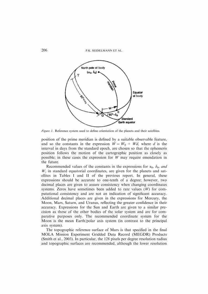
The north pole is that pole of rotation that lies on the north side of theinvariable plane of the solar system. The direction of the north pole isspecified by the value of its right ascension a0 and declination d0, whereas thelocation of the prime meridian is specified by the angle that is measured alongthe planet’s equator in an easterly direction with respect to the planet’s northpole from the node Q (located at right ascension 90� + a0) of the planet’sequator on the standard equator to the point B, where the prime meridiancrosses the planet’s equator (see Figure 1). The right ascension of the point Qis 90� + a0 and the inclination of the planet’s equator to the standardequator is 90�)d0. Because the prime meridian is assumed to rotate uniformlywith the planet, W accordingly varies linearly with time. In addition, a0, d0,and W may vary with time due to a precession of the axis of rotation of theplanet (or satellite). If W increases with time, the planet has a direct (orprograde) rotation, and if W decreases with time, the rotation is said to beretrograde.
In the absence of other information, the axis of rotation is assumed to benormal to the mean orbital plane; Mercury and most of the satellites are inthis category. For many of the satellites, it is assumed that the rotation rate isequal to the mean orbital period.
The angle W specifies the ephemeris position of the prime meridian,and for planets or satellites without any accurately observable fixed sur-face features, the adopted expression for W defines the prime meridianand is not subject to correction. Where possible, however, the cartographic
REPORT OF THE IAU/IAG WORKING GROUP 205
position of the prime meridian is defined by a suitable observable feature,and so the constants in the expression W ¼W0 + Wd, where d is theinterval in days from the standard epoch, are chosen so that the ephemerisposition follows the motion of the cartographic position as closely aspossible; in these cases the expression for W may require emendation inthe future.
Recommended values of the constants in the expressions for a0, d0, andW, in standard equatorial coordinates, are given for the planets and sat-ellites in Tables I and II of the previous report. In general, theseexpressions should be accurate to one-tenth of a degree; however, twodecimal places are given to assure consistency when changing coordinatessystems. Zeros have sometimes been added to rate values (W) for com-putational consistency and are not an indication of significant accuracy.Additional decimal places are given in the expressions for Mercury, theMoon, Mars, Saturn, and Uranus, reflecting the greater confidence in theiraccuracy. Expressions for the Sun and Earth are given to a similar pre-cision as those of the other bodies of the solar system and are for com-parative purposes only. The recommended coordinate system for theMoon is the mean Earth/polar axis system (in contrast to the principalaxis system).
The topographic reference surface of Mars is that specified in the finalMOLA Mission Experiment Gridded Data Record (MEGDR) Products(Smith et al., 2003). In particular, the 128 pixels per degree resolution radiusand topographic surfaces are recommended, although the lower resolution
Figure 1. Reference system used to define orientation of the planets and their satellites.
P.K. SEIDELMANN ET AL.206
versions may be used where appropriate and documented, and for the areaspoleward of ±88� latitude.
3. Rotational Elements for Asteroids and Comets
For planets and satellites the IAU definition of north pole is the pole that liesabove the invariant plane of the solar system, and the rotation can be eitherprograde or retrograde. For asteroids and comets, given substantial indirectevidence for large precession of the rotational poles of some comets, this firstdefinition needs to be rethought, in anticipation of situations in which thepole that is clearly ‘‘north’’ in the IAU sense precesses over several decades tobecome clearly ‘‘south’’ in the IAU sense. Comet 2P/Encke, which is likely tobe visited by spacecraft in the foreseeable future, is a prime example of acomet for which very large precession has been inferred.
There is also clear evidence for excited state rotation at least for comet 1P/Halley. In this case, the angular momentum vector moves around on thesurface of the body. The rotational spin vector describes substantial excur-sions from the angular momentum vector during the course of the 7-dayperiodicity that is seen in the light curve. We can, therefore, anticipate casesin which the rotational spin pole moves back and forth between north andsouth on a time scale of days. So there is the issue of needing to change ourdefinition of the rotational pole.
The choice of a rotational pole for a body in simple rotation with slowprecession is straightforward. One can choose the pole that follows either theright-hand rule or the left-hand rule, and the right-hand rule is chosen here.This would be the ‘‘positive’’ pole to avoid confusion with the north-southterminology. Ideally one would like to choose a pole for excited state rotationthat reduces to this definition as the rotational energy relaxes to the groundstate. For SAM (short-axis mode) rotational states, it is possible to define abody-fixed axis that circulates in a generally complex pattern about theangular momentum vector and this approaches the simple right-hand ruledefinition as the rotational energy relaxes to the ground state of simplerotation. Presumably the appropriate body-fixed pole is the axis of maximummoment of inertia. However, the definition for a body in a LAM (long-axismode) rotational state is not so obvious, since there is then complete rotationabout the long axis of the body as well as rotation about a short axis. In thiscase, the pole should be taken as the minimum moment of inertia (the longaxis of an ellipsoid) according to the right-hand rule.
Increasing longitude should also follow the right-hand rule rather thanfollow the rule that longitude should increase monotonically for an observerfixed in inertial space. With the above definitions of poles, the latter definition
REPORT OF THE IAU/IAG WORKING GROUP 207
of longitude corresponds always to a left-hand rule for increasing longitude,since the concept of retrograde rotation is no longer relevant. The latter wouldcorrespond to the coordinates used for Eros by Thomas et al. (2002),(fortunately the positive pole of Eros is in the north) while the former corre-sponds to the sense of increasing longitude used by Miller et al. (2002).
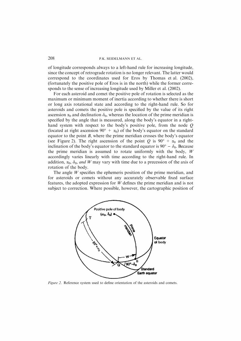
For each asteroid and comet the positive pole of rotation is selected as themaximum or minimum moment of inertia according to whether there is shortor long axis rotational state and according to the right-hand rule. So forasteroids and comets the positive pole is specified by the value of its rightascension a0 and declination d0, whereas the location of the prime meridian isspecified by the angle that is measured, along the body’s equator in a right-hand system with respect to the body’s positive pole, from the node Q(located at right ascension 90� + a0) of the body’s equator on the standardequator to the point B, where the prime meridian crosses the body’s equator(see Figure 2). The right ascension of the point Q is 90� + a0 and theinclination of the body’s equator to the standard equator is 90� ) d0. Becausethe prime meridian is assumed to rotate uniformly with the body, Waccordingly varies linearly with time according to the right-hand rule. Inaddition, a0, d0, and W may vary with time due to a precession of the axis ofrotation of the body.
The angle W specifies the ephemeris position of the prime meridian, andfor asteroids or comets without any accurately observable fixed surfacefeatures, the adopted expression for W defines the prime meridian and is notsubject to correction. Where possible, however, the cartographic position of
Figure 2. Reference system used to define orientation of the asteroids and comets.
P.K. SEIDELMANN ET AL.208
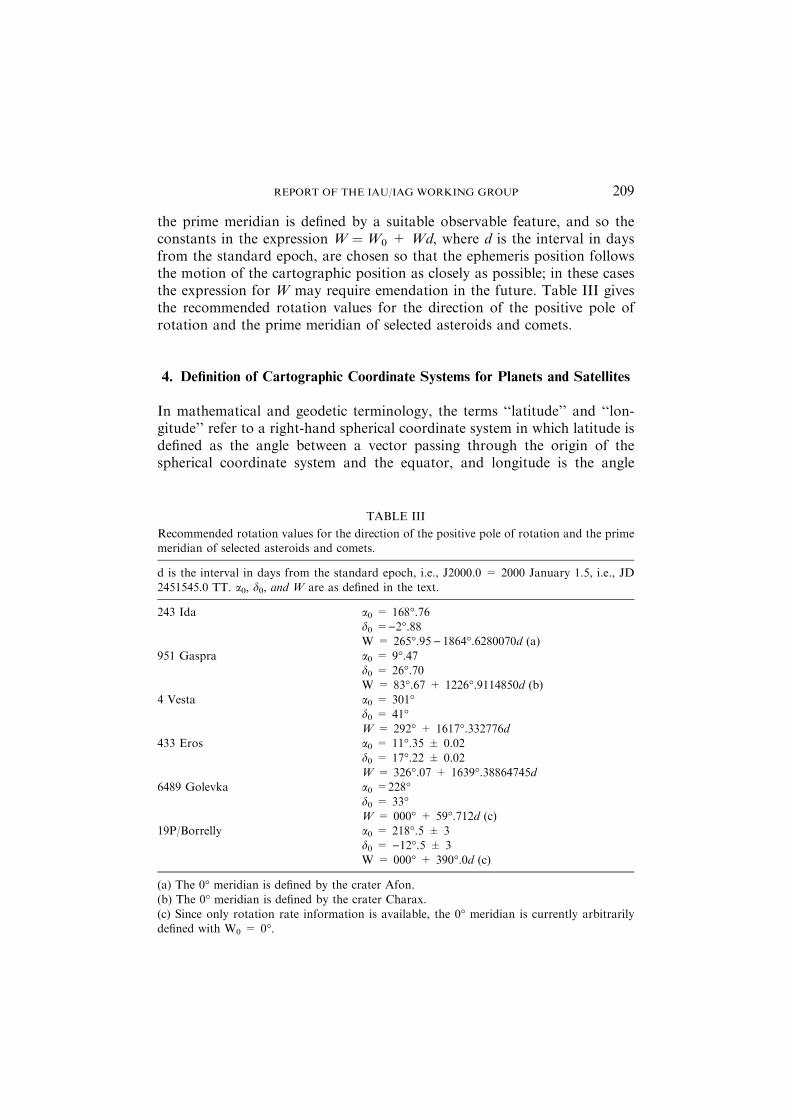
the prime meridian is defined by a suitable observable feature, and so theconstants in the expression W ¼W0 + Wd, where d is the interval in daysfrom the standard epoch, are chosen so that the ephemeris position followsthe motion of the cartographic position as closely as possible; in these casesthe expression for W may require emendation in the future. Table III givesthe recommended rotation values for the direction of the positive pole ofrotation and the prime meridian of selected asteroids and comets.
4. Definition of Cartographic Coordinate Systems for Planets and Satellites
In mathematical and geodetic terminology, the terms ‘‘latitude’’ and ‘‘lon-gitude’’ refer to a right-hand spherical coordinate system in which latitude isdefined as the angle between a vector passing through the origin of thespherical coordinate system and the equator, and longitude is the angle
TABLE III
Recommended rotation values for the direction of the positive pole of rotation and the primemeridian of selected asteroids and comets.
d is the interval in days from the standard epoch, i.e., J2000.0 = 2000 January 1.5, i.e., JD2451545.0 TT. a0, d0, and W are as defined in the text.
243 Ida a0 = 168�.76d0 =)2�.88W = 265�.95) 1864�.6280070d (a)
951 Gaspra a0 = 9�.47d0 = 26�.70W = 83�.67 + 1226�.9114850d (b)
4 Vesta a0 = 301�d0 = 41�W = 292� + 1617�.332776d
433 Eros a0 = 11�.35 ± 0.02
d0 = 17�.22 ± 0.02W = 326�.07 + 1639�.38864745d
6489 Golevka a0 =228�d0 = 33�W = 000� + 59�.712d (c)
19P/Borrelly a0 = 218�.5 ± 3
d0 = )12�.5 ± 3W = 000� + 390�.0d (c)
(a) The 0� meridian is defined by the crater Afon.(b) The 0� meridian is defined by the crater Charax.
(c) Since only rotation rate information is available, the 0� meridian is currently arbitrarilydefined with W0 = 0�.
REPORT OF THE IAU/IAG WORKING GROUP 209
between the vector and the plane of the prime meridian measured in aneastern direction. This coordinate system, together with Cartesian coordi-nates, is used in most planetary computations, and is sometimes called theplanetocentric coordinate system. The origin is the center of mass.
Because of astronomical tradition, planetographic coordinates (thosecommonly used on maps) may or may not be identical with traditionalspherical coordinates. Planetographic coordinates are defined by guidingprinciples contained in a resolution passed at the fourteenth GeneralAssembly of the IAU in 1970. These guiding principles state that
(1) The rotational pole of a planet or satellite which lies on the north side ofthe invariable plane will be called north, and northern latitudes will bedesignated as positive.
(2) The planetographic longitude of the central meridian, as observed from adirection fixed with respect to an inertial system, will increase with time.The range of longitudes shall extend from 0� to 360�.
Thus, west longitudes (i.e., longitudes measured positively to the west) willbe used when the rotation is prograde and east longitudes (i.e., longitudesmeasured positively to the east) when the rotation is retrograde. The origin isthe center of mass. Also because of tradition, the Earth, Sun, and Moon donot conform with this definition. Their rotations are prograde and longitudesrun both east and west 180�, or east 360�.
For planets and satellites, latitude is measured north and south of theequator; north latitudes are designated as positive. The planetographic latitudeof a point on the reference surface is the angle between the equatorial plane andthe normal to the reference surface at the point. In the planetographic system,the position of a point (P) not on the reference surface is specified by theplanetographic latitude of the point (P¢) on the reference surface at which thenormal passes through P and by the height (h) of P above P¢.
The reference surfaces for some planets (such as Earth and Mars) areellipsoids of revolution for which the radius at the equator (A) is larger thanthe polar semi-axis (C).
Calculations of the hydrostatic shapes of some of the satellites (Io, Mimas,Enceladus, and Miranda) indicate that their reference surfaces should betriaxial ellipsoids. Triaxial ellipsoids would render many computations morecomplicated, especially those related to map projections. Many projectionswould lose their elegant and popular properties. For this reason sphericalreference surfaces are frequently used in mapping programs.
Many small bodies of the solar system (satellites, asteroids, and cometnuclei) have very irregular shapes. Sometimes spherical reference surfaces areused for computational convenience, but this approach does not preserve thearea or shape characteristics of common map projections. Orthographic
P.K. SEIDELMANN ET AL.210
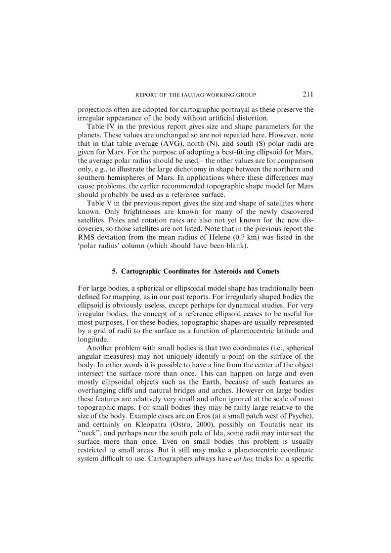
projections often are adopted for cartographic portrayal as these preserve theirregular appearance of the body without artificial distortion.
Table IV in the previous report gives size and shape parameters for theplanets. These values are unchanged so are not repeated here. However, notethat in that table average (AVG), north (N), and south (S) polar radii aregiven for Mars. For the purpose of adopting a best-fitting ellipsoid for Mars,the average polar radius should be used – the other values are for comparisononly, e.g., to illustrate the large dichotomy in shape between the northern andsouthern hemispheres of Mars. In applications where these differences maycause problems, the earlier recommended topographic shape model for Marsshould probably be used as a reference surface.
Table V in the previous report gives the size and shape of satellites whereknown. Only brightnesses are known for many of the newly discoveredsatellites. Poles and rotation rates are also not yet known for the new dis-coveries, so those satellites are not listed. Note that in the previous report theRMS deviation from the mean radius of Helene (0.7 km) was listed in the‘polar radius’ column (which should have been blank).
5. Cartographic Coordinates for Asteroids and Comets
For large bodies, a spherical or ellipsoidal model shape has traditionally beendefined for mapping, as in our past reports. For irregularly shaped bodies theellipsoid is obviously useless, except perhaps for dynamical studies. For veryirregular bodies, the concept of a reference ellipsoid ceases to be useful formost purposes. For these bodies, topographic shapes are usually representedby a grid of radii to the surface as a function of planetocentric latitude andlongitude.
Another problem with small bodies is that two coordinates (i.e., sphericalangular measures) may not uniquely identify a point on the surface of thebody. In other words it is possible to have a line from the center of the objectintersect the surface more than once. This can happen on large and evenmostly ellipsoidal objects such as the Earth, because of such features asoverhanging cliffs and natural bridges and arches. However on large bodiesthese features are relatively very small and often ignored at the scale of mosttopographic maps. For small bodies they may be fairly large relative to thesize of the body. Example cases are on Eros (at a small patch west of Psyche),and certainly on Kleopatra (Ostro, 2000), possibly on Toutatis near its‘‘neck’’, and perhaps near the south pole of Ida, some radii may intersect thesurface more than once. Even on small bodies this problem is usuallyrestricted to small areas. But it still may make a planetocentric coordinatesystem difficult to use. Cartographers always have ad hoc tricks for a specific
REPORT OF THE IAU/IAG WORKING GROUP 211
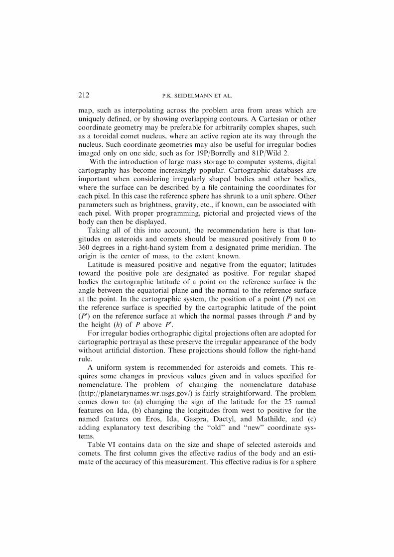
map, such as interpolating across the problem area from areas which areuniquely defined, or by showing overlapping contours. A Cartesian or othercoordinate geometry may be preferable for arbitrarily complex shapes, suchas a toroidal comet nucleus, where an active region ate its way through thenucleus. Such coordinate geometries may also be useful for irregular bodiesimaged only on one side, such as for 19P/Borrelly and 81P/Wild 2.
With the introduction of large mass storage to computer systems, digitalcartography has become increasingly popular. Cartographic databases areimportant when considering irregularly shaped bodies and other bodies,where the surface can be described by a file containing the coordinates foreach pixel. In this case the reference sphere has shrunk to a unit sphere. Otherparameters such as brightness, gravity, etc., if known, can be associated witheach pixel. With proper programming, pictorial and projected views of thebody can then be displayed.
Taking all of this into account, the recommendation here is that lon-gitudes on asteroids and comets should be measured positively from 0 to360 degrees in a right-hand system from a designated prime meridian. Theorigin is the center of mass, to the extent known.
Latitude is measured positive and negative from the equator; latitudestoward the positive pole are designated as positive. For regular shapedbodies the cartographic latitude of a point on the reference surface is theangle between the equatorial plane and the normal to the reference surfaceat the point. In the cartographic system, the position of a point (P) not onthe reference surface is specified by the cartographic latitude of the point(P¢) on the reference surface at which the normal passes through P and bythe height (h) of P above P¢.
For irregular bodies orthographic digital projections often are adopted forcartographic portrayal as these preserve the irregular appearance of the bodywithout artificial distortion. These projections should follow the right-handrule.
A uniform system is recommended for asteroids and comets. This re-quires some changes in previous values given and in values specified fornomenclature. The problem of changing the nomenclature database(http://planetarynames.wr.usgs.gov/) is fairly straightforward. The problemcomes down to: (a) changing the sign of the latitude for the 25 namedfeatures on Ida, (b) changing the longitudes from west to positive for thenamed features on Eros, Ida, Gaspra, Dactyl, and Mathilde, and (c)adding explanatory text describing the ‘‘old’’ and ‘‘new’’ coordinate sys-tems.
Table VI contains data on the size and shape of selected asteroids andcomets. The first column gives the effective radius of the body and an esti-mate of the accuracy of this measurement. This effective radius is for a sphere
P.K. SEIDELMANN ET AL.212
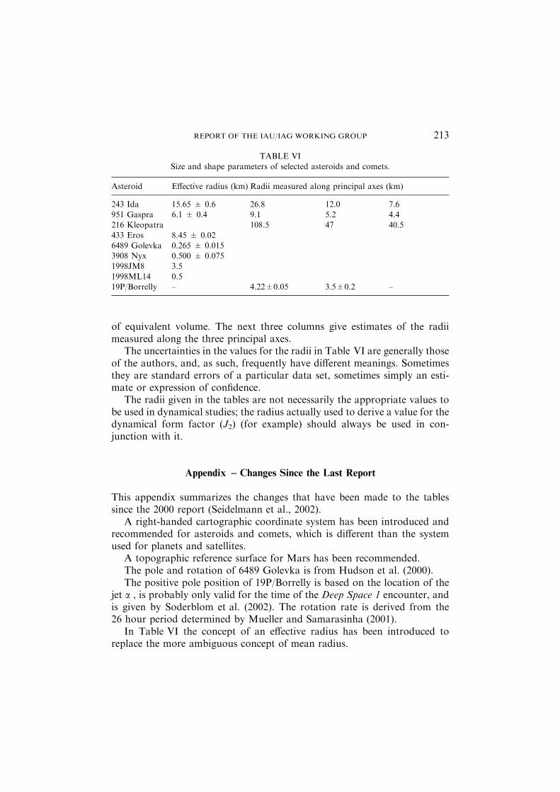
of equivalent volume. The next three columns give estimates of the radiimeasured along the three principal axes.
The uncertainties in the values for the radii in Table VI are generally thoseof the authors, and, as such, frequently have different meanings. Sometimesthey are standard errors of a particular data set, sometimes simply an esti-mate or expression of confidence.
The radii given in the tables are not necessarily the appropriate values tobe used in dynamical studies; the radius actually used to derive a value for thedynamical form factor (J2) (for example) should always be used in con-junction with it.
Appendix – Changes Since the Last Report
This appendix summarizes the changes that have been made to the tablessince the 2000 report (Seidelmann et al., 2002).
A right-handed cartographic coordinate system has been introduced andrecommended for asteroids and comets, which is different than the systemused for planets and satellites.
A topographic reference surface for Mars has been recommended.The pole and rotation of 6489 Golevka is from Hudson et al. (2000).The positive pole position of 19P/Borrelly is based on the location of the
jet a , is probably only valid for the time of the Deep Space 1 encounter, andis given by Soderblom et al. (2002). The rotation rate is derived from the26 hour period determined by Mueller and Samarasinha (2001).
In Table VI the concept of an effective radius has been introduced toreplace the more ambiguous concept of mean radius.
TABLE VISize and shape parameters of selected asteroids and comets.
Asteroid Effective radius (km) Radii measured along principal axes (km)
243 Ida 15.65 ± 0.6 26.8 12.0 7.6951 Gaspra 6.1 ± 0.4 9.1 5.2 4.4216 Kleopatra 108.5 47 40.5
433 Eros 8.45 ± 0.026489 Golevka 0.265 ± 0.0153908 Nyx 0.500 ± 0.0751998JM8 3.5
1998ML14 0.519P/Borrelly – 4.22±0.05 3.5±0.2 –
REPORT OF THE IAU/IAG WORKING GROUP 213
The radii of 6489 Golevka, 3908 Nyx, 1998 JM8, and 1998 ML14 are fromHudson et al. (2000), Benner et al. (2002a), Benner et al. (2002b), and Ostroet al. (2001), respectively.
The radii of 19P/Borrelly are estimates from Kirk (personal communi-cation, 2003). These are based on extrapolations of a digital terrain model ofthe visible portions of the comet (4.28 km · 3.00 km, with a minimum widthof 1.38 km, all ±0.05 km) to likely maximum radii, from work published byKirk et al. (2004).
Acknowledgement
We appreciate the efforts of Mark Rosiek, who assisted in the creation of theFigures.
References
Benner, L. A. M., Ostro, S. J., Hudson, R.S., et al.: 2002a, ‘Radar observations of asteroid
3908 Nyx’, Icarus, 158, 379–388.Benner, L. A. M., Ostro, S. J., Nolan, M. C., et al.: 2002b, ‘Radar observations of asteroid
1999 JM8’, Meteorites & Planet Scien, 37, 779–792.Hudson, R. S., Ostro, S. J., Jurgens, R. F., et al.: 2000, ‘Radar observations and physical
model of asteroid 6489 Golevka’, Icarus, 148, 37–51.Kirk, R. L., Howington-Kraus, E., Soderblom, L. A., Giese, B. and Oberst, J.: 2004, ‘Com-
parison of USGS and DLR topographic models of Comet Borrelly and photometric
applications’, Icarus, 167, 54–69.Ma, C., Arias, E. F., Eubanks, T. M., Fey, A. L., Gontier, A.-M., Jacobs, C. S., Sovers, O. J.,
Archinal, B. A. and Charlot, P.: 1998, ‘The international celestial reference frame as
realized by very long baseline interferometry’, Astron. J., 116, 516–546.Miller, J. K., Konopliv, A. S., Antreasian, P. G., Bordi, J. J., Chesley, S., Helfrich, C. E.,
Owen, W. M., Wang, T. C., Williams, B. G., Yeomans, D. K. and Scheeres, D. J.: 2002,
‘Determination of shape, gravity, and rotational state of asteroid 433 Eros’, Icarus, 155, 3–17.
Mueller, B. and Samarasinha, N.: 2001, ‘Lightcurve observations of 19P/Borrelly’, Bull. Am.Astron. Soc., 33, 1090.
Ostro, S. J., Hudson, R. S., Nolan, M. C., Margot, J.-L., Scheeres, D. J., Campbell, D. B.,Magri, C., Giosini, J. D., and Yeomans, D. K.: 2000, ‘Radar observations of asteroid 216Kleopatra’, Science, 288, 836–839, 5 May.
Ostro, S. J., Hudson, R. S., Benner, L. A. M., et al.: 2001, ‘Radar observations of asteroid1998ML14’, Meteorites & Planet Scien., 36, 1225–1236.
Seidelmann, P. K., Abalakin, V. K., Bursa, M., Davies, M. E., de Bergh, C., Lieske, J. H.,
Oberst, J., Simon, J. L., Standish, E. M., Stooke, P. and Thomas, P. C.: 2002, ‘Report ofthe IAU/IAG Working group on cartographic coordinates and rotational elements of theplanets and satellites: 2000’, Celest. Mech. Dyn. Astron., 82, 83–110.
P.K. SEIDELMANN ET AL.214
Smith, D., Neumann, B., Arvidson, R. E., Guinness, E. A. and Slavney, S.: 2003, ‘Mars globalsurveyor laser altimeter mission experiment gridded data record’, NASA Planetary Data
System, MGS-M-MOLA-5-MEGDR-L3-V1.0, 2003. Available on-line from http://pds-geosciences.wustl.edu/missions/mgs/mola.html.
Soderblom, L.A., Becker, T. L., Bennett, G., Boice, D. C., Britt, D. T., Brown,R.H., Buratti, B.
J., Isbell, C., Giese, B., Hare, T., Hicks, M. D., Howington-Kraus, E., Kirk, R. L., Lee, M.,Nelson, R.M., Oberst, J., Owen, T. C., Rayman,M.D., Sandel, B. R., Stern, S. A., Thomas,N. and Yelle, R.V.: 2002, ‘Observations of comet 19P/Borrelly by the miniature integratedcamera and spectrometer aboard Deep Space 1’, Science, 296, 1087–1091, May 10.
REPORT OF THE IAU/IAG WORKING GROUP 215