report of thermal power plant
TRANSCRIPT

8/11/2019 Report of Thermal Power Plant
http://slidepdf.com/reader/full/report-of-thermal-power-plant 1/92
THERMAL POWER PLANT
A PROJECT REPORT
Submitted by
PRAMOD KUMAR
in partial fulfillment for the award of the degree
B.Tech
IN
MECHANICAL BRANCH
RIMT Institute of Engineering and Technoog!
Mandi "o#indgarh
P$NJAB TECHNICAL $NI%ER&IT'( JALAN)HAR *+,,-+
JAN* MA' /0+1
1

8/11/2019 Report of Thermal Power Plant
http://slidepdf.com/reader/full/report-of-thermal-power-plant 2/92
AC2NOWLE)"EMENT
I am extremely thankful for having been able to receive in-plant training and
submit this report at the )ahanu Ther3a Po4er &tation /)TP&1( a unanimous
part of the Reliance Energy Ltd. (REL)
I express my deep sense of gratitude to Mr. Prasad Rao( station head of !"#
Mr. R.Nandi( $ead (% & ') and Mrs.%an4ai chanda( $R(corporateoffice'umbai) for giving me this opportunity in this plant . I am also thankful to
Mr. A.).Pati ' 'echanical ept. & Mr. C.B.Ne3ade( $% of 'echanical
'aintenance ept. for his co- operation.
I also thank Mr. %i5a! "andhe4ar( #r. 'anager (!rg.) and Mr."irish.P.Bidi6ar
#r. 'anager ('ech. 'aintenance ept.) for their perennial help and ideas to make
the report better and uni*ue.
Last but not the least I +ish to thank the highly dedicated and motivated team at
!"# for making me a part of their team and making the training an exclusive
experience.
2

8/11/2019 Report of Thermal Power Plant
http://slidepdf.com/reader/full/report-of-thermal-power-plant 3/92
"L,! L%,!I%
,$,/ !$ER',L "%0ER #!,!I% 1ILL,E - ,0, ,$,/
R%, I#!2 !$,E- 345 647
REI#!ERE , %R"%R,!E %88IERELI,E EER9 E!RE
#,!,R/: (E,#!) '/';,I- 3444<<
3

8/11/2019 Report of Thermal Power Plant
http://slidepdf.com/reader/full/report-of-thermal-power-plant 4/92
INTRO)$CTION
In recent years India=s energy consumption has been increasing at one of the
fastest rates in the +orld due to population gro+th and economic development.
ommercial primary energy consumption in India has gro+n by about >44? in the
last four decades. !he per capita consumption in India is in the region of 344 @0$
per annum. riven by the rising population expanding economy and a *uest for
improved *uality of life energy usage in India is expected to gro+ at a exponential
rate.
espite the overall increase in energy demand per capita energy consumption in
India is still very lo+ compared to other developing countries. !oday India has one
of the highest potentials for the effective use of rene+able energy. India is the
+orld=s fifth largest producer of +ind po+er after enmark ermany #pain and
the /#,. !here is a significant potential in India for generation of po+er from
rene+able energy sources- small hydro biomass and solar energy. !he country
has an estimated #$" (small-hydro po+er) potential of about 5<444 '0.
4

8/11/2019 Report of Thermal Power Plant
http://slidepdf.com/reader/full/report-of-thermal-power-plant 5/92
ENER"' &CENARIO IN IN)IA
Energy is the prime mover of economic gro+th and is vital to the sustenance
of a modern economy. 8uture economic gro+th crucially depends on the long-term
availability of energy from sources that are affordable accessible and
environmentally friendly.
India ranks sixth in the +orld in total energy consumption and needs to
accelerate the development of the sector to meet its gro+th aspirations. !he
country though rich in coal and oal meets approximately 6A percent of the
country=s total energy re*uirements. ,ccording to current estimates the reserves
are sufficient to meet India=s needs for at least another 544 years. India no+ ranks
Ard amongst the coal producing countries in the +orld
If +e look at the pattern of energy production coal and oil account for <3 percent and A3 percent respectively +ith natural gas hydro and nuclear
contributing to the balance. In the po+er generation front nearly 67 percent of
po+er generation is from coal fired thermal po+er plants and >4 percent of the
coal produced every year in India has been used for thermal generation.
%n the consumption front the industrial sector in India is a maBor energy
user accounting for about <7 percent of commercial energy consumption. "er
capita energy consumption in India is one of the lo+est in the +orld but energy
intensity +hich is energy consumption per unit of " is one of the highest in
comparison to other developed and developing countries !hus there is a huge
scope for energy conservation in the country.
5

8/11/2019 Report of Thermal Power Plant
http://slidepdf.com/reader/full/report-of-thermal-power-plant 6/92
8/11/2019 Report of Thermal Power Plant
http://slidepdf.com/reader/full/report-of-thermal-power-plant 7/92
India has huge coal reserves at least C3A6 million tonnes of proven recoverable
reserves (at the end of 744A). !his amount to almost C.6? of the +orld reserves
and it may last for about 7A4 years at the current Reserve to "roduction (RF") ratio.
In contrast the +orldGs proven coal reserves are expected to last only for 57 years
at the current RF" ratio.
Oi
%il accounts for about A6 ? of IndiaGs total energy consumption. India today is one
of the top ten oil-guDDling nations in the +orld and +ill soon overtake @orea as the
third largest consumer of oil in ,sia after hina and Hapan.
"as tur#ine 8o4er 8ants /Natura "as1
atural gas accounts for about C.? of energy consumption in the country. !he
current demand for natural gas is about 6 million cubic meters per day (mcmd) as
against availability of 6> mcmd. ;y 744> the demand is expected to be around
744 mcmd. atural gas reserves are estimated at 664 billion cubic meters.
Eectrica Energ!
!he all India installed capacity of electric po+er generating stations under utilities
+as 557<C5 '0 as on A5st 'ay 7443 consisting of 7CC64 '0- hydro >>A5
'0 - thermal and 7>74 '0- nuclear and 5C6 '0- +ind ('inistry of "o+er).
!he gross generation of po+er in the year 7447-744A stood at <A5 billion units
(k0h).
Nucear Po4er 8ant
7

8/11/2019 Report of Thermal Power Plant
http://slidepdf.com/reader/full/report-of-thermal-power-plant 8/92
uclear "o+er contributes to about 7.3 per cent of electricity generated in India.
India has ten nuclear po+er reactors at five nuclear po+er stations producing
electricity. 'ore nuclear reactors have also been approved for construction.
H!dro Po4er 8ant
India is endo+ed +ith a vast and viable hydro potential for po+er generation of
+hich only 5<? has been harnessed so far. !he share of hydropo+er in the
countryGs total generated units has steadily decreased and it presently stands at 7<?
as on A5st 'ay 7443. It is assessed that exploitable potential at 64? load factor is
C3444 '0.
&ource units +::,*:; 0+*0 0-*< 0++*0+0
Eectricit! #iion
units 7C.A6 3C4.4C >57.6> 546>.CC
Coa 3iion tonnes >6.6> 54.45 5A3. 5>A.3>
Lignite 3iion tones
3.C<
55.6 56.47 5.>4
Natura gas 3iion
cu#ic 3eters CC4 5<>A4 5C75 74C<A
Oi 8roducts 3iion
tonnes 6A.<<
.C 5A.< 56.3>
The actua fina energ! consu38tion /8ast and 8ro5ected1 is gi=en in Ta#e*0
8

8/11/2019 Report of Thermal Power Plant
http://slidepdf.com/reader/full/report-of-thermal-power-plant 9/92
;,#I 0%R@I %8 !$ER'EL "%0ER "L,!
, modern pulveriDed coal-fired electricity generation facility that uses the most
commonly employed Rankine-based thermodynamic cycle .#team at the desired
pressure temperature and mass flo+ is produced in a steam generator and
expanded through a turbine generator. !he exhausted stem is no+ condensed in a
condenser and the condensed li*uid is used again in the steam generator.
oal is delivered to the facility by rail+ay +agons barges or trucks using sea link.
!he coal handling system unloads the coal stocks reclaims crushes and conveys it
to storage silos. oal from the silos is then pulveriDed to a fine po+der and then
blo+n into the steam generator +here it is mixed +ith air and combusted to release
energy for the generation of steam .!he steam generators produces superheats and
reheats steam as it proceeds through the cycle.
!he steam turbine generator converts the thermal energy of the superheated and
reheated steam to electrical energy. #team exhausted from the turbine is condensed
to li*uid in the condenser. !he condensate pump feed the +ater through the I.p
regenerative feed +ater heaters to a deaerator .boiler feed pumps move thedeaerated li*uid through the h.p feed +ater heaters back to the steam generator
8orced draught fan (8. fan) supply combustion air to the steam generator and the
primary air fan ("., 8an) transport pulveriDed coal into the burners. Induced
9

8/11/2019 Report of Thermal Power Plant
http://slidepdf.com/reader/full/report-of-thermal-power-plant 10/92
draught fans remove the flue gases from the furnace and exhaust them through the
stack into the atmosphere.
ooling +ater from the condenser is supplied by the circulating +ater system
+hich takes the heat removed from the condenser and reBects it to cooling to+ers
or another heat sink such as cooling lake river or sea.
ombustion gases coming out of the steam generator re*uire additional treatment
for removal of fly ash particulates sulphur dioxide and nitrogen oxides before the
gases are released through the exhaust stack
10

8/11/2019 Report of Thermal Power Plant
http://slidepdf.com/reader/full/report-of-thermal-power-plant 11/92
ABO$T
)AHAN$ THERMAL POWER PLANT
/RELIANCE ENER"' LT).1
11
8/11/2019 Report of Thermal Power Plant
http://slidepdf.com/reader/full/report-of-thermal-power-plant 12/92
CONTENT&
+. OR"ANI&ATION PRO7ILE +,
+.+ Introduction +,
+.0 A#out )ahanu Ther3a Po4er &tation +;
+.> Po4er "eneration Process +:
0. MECHANICAL MAINTENANCE )EPARTMENT 0;
0.+ Boier Maintenance 0;
0.0 Boier Pressure Parts Maintenance 0;
0.> Boier Rotar! Parts Maintenance ><
0., Tur#ine Maintenance ,;
>. O77&ITE A$?ILIAR' $NIT& -,
>.+ Ash handing 8u38 house -,
>.0 Coa handing area -<
>.> C.W 8u38 house <:>., Water 8retreat3ent 8ant @+
>.; )e3ineraisation 8ant @,
12
8/11/2019 Report of Thermal Power Plant
http://slidepdf.com/reader/full/report-of-thermal-power-plant 13/92
+. OR"ANI&ATION PRO7ILE
+.+ INTRO)$CTION9
!he ;#E# (;ombay #uburban Electricity #upply) is incorporated in 57.
!he company got license to distribute electricity in areas of 'umbai. It generates
and supply electricity to 'umbai city and its suburbs. 8rom the modest license
supplying po+er to suburbs of 'umbai ;#E# today is a multi occasional and
multi dimensional enterprise.
In the process the company has emerged as the country leading integrated
po+er company +ith activities spanning the entire po+er process right from
concept to the consumption of the electric energy.
;#E# +ith its corporate lineage going back to 57 is India=s premier /tility
engaged in the generation transmission and distribution of electricity in and
around 'umbai. It provides portfolio of value added services in electrical
13

8/11/2019 Report of Thermal Power Plant
http://slidepdf.com/reader/full/report-of-thermal-power-plant 14/92

8/11/2019 Report of Thermal Power Plant
http://slidepdf.com/reader/full/report-of-thermal-power-plant 15/92
REL and its affiliate po+er companies rank among the top 7< listed private
sector companies on maBor financial parameters. REL is part of the Reliance
industries-IndiaGs private sector company ranked among the +orldGs 5>< largest
companies in terms of net profit and the <44 largest companies in terms of sales.
REL is committed to creating superior value for all its stakeholders and be
amongst the most admired and trusted utility companies in the +orld by setting
ne+ benchmarks in standards of corporate governance operational and financial
excellence responsible corporate citiDenship and profitable gro+th.
+.0 ABO$T )AHAN$ THERMAL POWER &TATION9
eneration division is located at ahanu ist. !hane in orth-0est of
'aharashtra nearly about 574 @m from 'umbai. It is called as ahanu !hermal
"o+er #tation (!"#). !he second unit +as test synchroniDed in a record time of
less than three months. !his <44 '0 "o+er #tation +as declared commercial in
Hune #ince then it has crossed several milestones and achieved a number of
laurels as best operating po+er station and for its environment friendly operation.
!he manpo+er of the company incorporates the services of 74> executive and A43
non executives (i.e. +orkers). It also employee=s 644->44 contract labours. It
makes use of combustion process for the generation of heat.
15

8/11/2019 Report of Thermal Power Plant
http://slidepdf.com/reader/full/report-of-thermal-power-plant 16/92
Reliance Energy .!.".#. is coal based !hermal po+er station +hich takes
coal sea +ater oil as inputs for producing electricity as one of the maBor output
including ash flue gases other outputs.
BA&IC PRINCIPLE O7 PLANT9
ahanu !hermal "o+er #tation is totally based on modified Rankine=s
cycle.'odified Rankine=s cycle is a vapour cycle having t+o basic characteristics2
!he +orking fluid is condensable vapour +hich is in li*uid phase during part
of the cycle.
!he cycle consist of succession of steady flo+ process +ith each process
carried out in a separate components +hich is specially design for the
purpose. Each consists an open system and all the components are
connected in series so that the cycle is close.
&ALIENT 7EAT$RE& O7 )TP&9
5. I#% 447 uality management
7. I#% 53445 Environmental 'anagement
A. In 5C certified by ;1I.
16

8/11/2019 Report of Thermal Power Plant
http://slidepdf.com/reader/full/report-of-thermal-power-plant 17/92

8/11/2019 Report of Thermal Power Plant
http://slidepdf.com/reader/full/report-of-thermal-power-plant 18/92
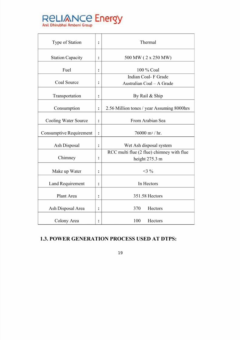
The Technica &8ecifications a#out the 8ant are as foo4s9
18
8/11/2019 Report of Thermal Power Plant
http://slidepdf.com/reader/full/report-of-thermal-power-plant 19/92
+.>. POWER "ENERATION PROCE&& $&E) AT )TP&9
19
!ype of #tation 9 !hermal
#tation apacity 9 <44 '0 ( 7 x 7<4 '0)
8uel 9 544 ? oal
oal #ource 9
Indian oal- 8 rade
,ustralian oal J , rade
!ransportation 9 ;y Rail & #hip
onsumption 9 7.<6 'illion tones F year ,ssuming C444hrs
ooling 0ater #ource 9 8rom ,rabian #ea
onsumptive Re*uirement 9 >6444 mA F hr.
,sh isposal 9 0et ,sh disposal system
himney 9
R multi flue (7 flue) chimney +ith flue
height 7><.A m
'ake up 0ater 9 KA ?
Land Re*uirement 9 In $ectors
"lant ,rea 9 A<5.<C $ectors
,sh isposal ,rea 9 A>4 $ectors
olony ,rea 9 544 $ectors
8/11/2019 Report of Thermal Power Plant
http://slidepdf.com/reader/full/report-of-thermal-power-plant 20/92
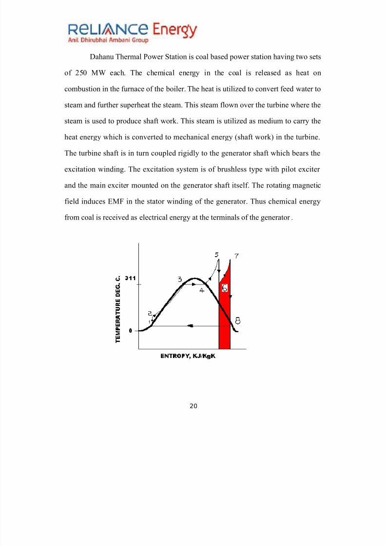
ahanu !hermal "o+er #tation is coal based po+er station having t+o sets
of 7<4 '0 each. !he chemical energy in the coal is released as heat on
combustion in the furnace of the boiler. !he heat is utiliDed to convert feed +ater to
steam and further superheat the steam. !his steam flo+n over the turbine +here the
steam is used to produce shaft +ork. !his steam is utiliDed as medium to carry the
heat energy +hich is converted to mechanical energy (shaft +ork) in the turbine.
!he turbine shaft is in turn coupled rigidly to the generator shaft +hich bears the
excitation +inding. !he excitation system is of brushless type +ith pilot exciter
and the main exciter mounted on the generator shaft itself. !he rotating magnetic
field induces E'8 in the stator +inding of the generator. !hus chemical energy
from coal is received as electrical energy at the terminals of the generator .
20

8/11/2019 Report of Thermal Power Plant
http://slidepdf.com/reader/full/report-of-thermal-power-plant 21/92
RE"ENERATI%E 7EE) HEATIN" C'CLE9*
In regenerative feed +ater heating cycle part of the steam is extracted after partial
expansion in the turbine and is used to heat up the feed +ater before going to the
boiler. In the process superheat and latent heat of extracted steam is transferred to
feed +ater to raise its temperature i.e. sensible heat addition in the feed +ater is
carried out before reaching the boiler. !he drop formed due to the condensation of
extracted steam is recycled in to feed +ater cycle at appropriate point.
7L$E "A& C'CLE9
!he boiler has furnace and heating parts. "ulveriDed coal is fired in the
furnace along +ith air re*uired for combustion. !o ignite the fire first light diesel
oil (L%) is fired in atomiDed form. , spark from Igniter 8lame 'onitoring (I8')
system ignites this oil. %nce the flame is stabiliDed on L% pulveriDed coal (>4-C4
micron siDe) is fired. !he arrangement of oil and coal burners is of tilting tangential
type (!!8). !his results in a vortex of flame revolving at a very speed. !his results
in a turbulent fire ball +hich ensures complete combustion. ;alanced draft of -< to
-54 mm of +ater column is maintained inside the boiler. !his ensures smooth flo+
of flue gas and proper dissipation of heat to the heating surfaces.
!he flue gas is finally passed over regenerative devices viD. economiDer
and ,ir preheater (,"$) to Electrostatic precipitator. $ere the ash from the flue
21
8/11/2019 Report of Thermal Power Plant
http://slidepdf.com/reader/full/report-of-thermal-power-plant 22/92
gas is collected and the flue gas consisting of #%7 is desulphuriDed in the 8 unit
and is then set out to atmosphere through chimney.
!he pulveriDed coal is carried to the boiler by hot "rimary ,ir. !his air is
made available by "rimary ,ir 8an. "art of cold primary air is passed through air
preheater +here it gets heated. It is then mixed +ith the cold primary air. $ot
primary air at desired temperature is then passed to coal mill from +here it carries
the coal. 8orced raft fan gives the (#,) +hich is actually the excess air re*uired
for combustion. !his air is also heated in ,"$ before passing to furnace. !hus
L% is fired initially. "ulveriDed coal "rimary ,ir and #econdary air form the
input to the furnace.
&TEAM C'CLE9
!he +alls of the first pass of boiler are made up of numerous tubes carrying
feed +ater (emineralised +ater). !herefore these +alls are called as +ater +alls.
!he furnace is located in the first pass itself +ith burner and air inBection assembly
being at the four corners formed by the +ater +alls. !hese +ater +alls originate
from a ;ottom Ring $eader (;R$) +hich is supplied +ith feed +ater from boiler
drum through do+n comers. !he boiler drum consists of a steam compartment and
+ater compartment. It has t+o turbo separators +ith AA separators in each ro+.
!urbo separators separate steam from steam +ater mixture.
22
8/11/2019 Report of Thermal Power Plant
http://slidepdf.com/reader/full/report-of-thermal-power-plant 23/92
!he heat evolved from combustion is transmitted to heating surfaces by
radiation and convection. !he +ater in the +ater +alls is heated and converted to
steam. ue to density difference the steam rises in the +ater +alls +hich are
terminated into top headers. !hese top headers are connected to the turbo
separators in the boiler drum. $ere +ater is separated by centrifugal action and it
falls back into drum and mixes +ith drum +ater. ry steam (C4?) rises up through
compartment. 8rom here the steam is passed through various superheating coils
located in the second pass and horiDontal pass in the boiler. !he steam from final
super heater header is passed to $igh "ressure !urbine through main steam pipe.
T$RBINE9
!he steam turbine at !"# is a A cylinder tandem compound @0/ make
(@raft 0orks /nion i.e. erman esign) 7<4 '0 steam turbine. It consists of
$igh "ressure turbine ($"!) Intermediate "ressure turbine (I"!) and Lo+
"ressure turbine (L"!). !he shafts of these turbines are axially coupled to each
other +ith rigid couplings. !he L"! shaft is coupled rigidly to the generator shaft
on the other end.
!he main steam from left and right side of the final super heater is
admitted at 53<-5<4 kgFcm7 pressure and <344 temperature to the $"!. ,t the exit
of $"! the steam has reduced parameters of around 34 kgFcm7 & A344. !he steam
is sent back to reheater in the boiler for reheating through old Reheat line (R$).
23

8/11/2019 Report of Thermal Power Plant
http://slidepdf.com/reader/full/report-of-thermal-power-plant 24/92
Reheating facilitates expansion of steam at reduced pressure due to comparative
higher temperatures. %ther+ise moisture formation may result at the ultimate
stages of L"!. !he reheated steam from left and right sides of the reheater header
is passed to the I"!.
#imilar to $"! I"! is also a single pass turbine. ;ut here the steam
expands in opposite direction as that in $"! thereby balancing the resultant thrust.
,t the exhaust of I"! the steam has reduced parameters of around >.<-C.4 kgFcm 7
pressure and A<4-A>44 temperature. !his steam is admitted to L"! +hich is a
double pass turbine. !he steam expands in either direction. !he exhaust of L"! is
connected to the condenser +hich is under vacuum pressure of 4.C kgFcm7.
24
LPT
B/DRUM ECO LTSH
PSH
FSH
FURNACE
IPT HPT
CONDEN. HOT WELL DEA BFP
2470c 2920c
5400c 3440
c
5400c
5030c
3930c
3510c
155 Kg/cm2
164 Kg/cm2
168 Kg/cm2173 Kg/cm2
40
Kg/cm2
37
Kg/cm2
C R
H H R
H
Sensible heat addition atent heat
FEED HEATERS
8/11/2019 Report of Thermal Power Plant
http://slidepdf.com/reader/full/report-of-thermal-power-plant 25/92
#team is passed over tubes +hich are coated +ith titanium from inside. #team
through these tubes carries the heat along +ith it. %nly latent heat from the steam
is removed so that it is converted to condensate. !his condensate is collected in a
hot +ell. ondensate Extraction "ump (E") is used to evacuate the condensate
from the hot +ell and to supply it to the regenerative circuit. !he regenerative
circuit consists of a land #team ooler rain cooler (3<42 77 kgFcm7) Lo+
pressure heaters (L"$) eaerator ;oiler 8eed "ump (;8"2 56442 54-5<
kgFcm7) $igh "ressure $eaters ($"$) and EconomiDer. ,s seen after the drain
cooler the condensate can be passed through the condensate polishing unit to
maintain its *uality ("$). !he gland steam cooler receives heat from the turbine
gland seal steam coming to condenser +hereas turbine drains are connected to the
drain cooler.
!he L"$5 is placed directly inside the condenser +hereas L"$
7 and L"$
A
receive heat from extractions from L"!. !he hot condensates pass to deaerator
+here dissolved gases are removed. 8eed +ater thus available is stored in 8eed
+ater storage tank. !his tank is connected to the suction of the booster pump. !he
discharge of the booster pump is connected to the suction of the main feed +ater
pump (80"). !he booster pump and main feed +ater pump form the boiler feeder
pump. ;oth the pumps are run by a single motor. ;ooster pump is directly
connected +hereas main 80" is coupled via hydraulic coupling. $ydraulic
25

8/11/2019 Report of Thermal Power Plant
http://slidepdf.com/reader/full/report-of-thermal-power-plant 26/92
coupling facilities stepless control for feed flo+. !he ;oiler 8eeder "ump
discharge is connected to $"$6 through $"$
<. !hese heaters receive heat from
extractions from I"!. !he discharge of $"6 is connected to the economiDer via
8eed Regulating 1alves station.
!he economiDer outlet is connected to the +ater compartment of boiler
drum. !hus the feed and condensate cycle is completed as a close loop. !he drips
of all the regenerative heaters are connected back to the condenser to avoid loss of
emineralised +ater.
"ENERATION O7 POWER9
In pilot exciter permanent magnet on the rotating shaft induces emf in its
stator +indings. !he output is passed through a complex thyristor based
circuit. !he controlled .. supply is fed to the main exciter stator +inding.
Emf induced in the rotor +inding of the main exciter is rectified and
connected to the rotor +inding. !he level being 7AC6 ,mperes at A5 1 ..
Emf is induced in the stator +inding of the generator at 56.<@1 and 5474
,mperes at 4.C< p.f. lagging.
, part of the po+er generated is evacuated by a step do+n /nit ,uxiliary
!ransformer (/,!) 56.< @1F6.6 @1 to meet the auxiliary po+er
re*uirement.
26
8/11/2019 Report of Thermal Power Plant
http://slidepdf.com/reader/full/report-of-thermal-power-plant 27/92
!he generator bus duct is further connected to the enerator !ransformer
(!) +hich steps the voltage up to 7741 at around 5444 ,mperes. !he
output of the enerator !ransformer is connected to the s+itchyard +hich
feed the consumers through a net+ork of substation connected by
transmission lines.
,dditionally a #tation !ransformer (#!) connected to grid is provided +hich
is used at the initial start-up of the plant +hen both the units are not in
service.
0. MECHANICAL MAINTENANCE )EPARTMENT
7.5. ;oiler maintenance
7.5.5. ;oiler "ressure "art 'aintenance
7.5.7. ;oiler Rotary "art maintenance
7.7. !urbine 'aintenance
0.+.+ BOILER PRE&&$RE PART& MAINTENANCE
• ;oiler
• EconomiDer
• ;oiler rum
• o+n comers
• /p risers
27
8/11/2019 Report of Thermal Power Plant
http://slidepdf.com/reader/full/report-of-thermal-power-plant 28/92
• 0ater +alls
• #team cooled +alls
• #uper heaters
• Reheater
• esuperheater
• #afety valve
•#oot blo+ers
• Expansion and sealing
• ;uckstays
• 0ind box ,ssembly
BOILER9
!he boiler in !"# is a natural circulation single drum radiant heat
negative draft type +ith tilting tangential burner type. 8iring e*uipment
consists of remotely controllable $E, igniters air cooled oil guns and coal
noDDles.
!he elevations of coal noDDles are supplied +ith pulveriDed coal from tube
mills.
28
8/11/2019 Report of Thermal Power Plant
http://slidepdf.com/reader/full/report-of-thermal-power-plant 29/92
!he various auxiliaries include t+o air preheaters three tube mills t+o
primary ,ir fans t+o forced raft fans t+o Induced raft fans six #eal ,ir
8ans and a four pass Electrostatic "recipitator.
!he drum internals act as an interface bet+een the boiler and the drum.
!he function of drum is to separate +ater and steam from the mixture
generated in the furnace +alls.
T!8es of #oiers9
epends upon pressure boilers are classified as2
Industrial ;oiler- Less "ressure (64kgFcm7) and less temp.( A<44).
/tility ;oiler- $igh "ressure and $igh !emperature and generally used in
po+er generation.
#ingle rum (#ub-critical boiler) 8; and $R# boiler.
#uper-critical boiler. (8orced circulation).
Boier s8ecifications9
'anufacturer 2 ;$EL .E. esign
!ype 2 atural irculation ;alance
29
8/11/2019 Report of Thermal Power Plant
http://slidepdf.com/reader/full/report-of-thermal-power-plant 30/92
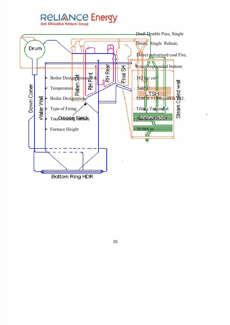
raft ouble "ass #ingle
rum #ingle Reheat
irect pulveriDed coal 8ire
0ater Impounded bottom.
;oiler esign "ressure & 2 5C7 kgF cmM
!emperature 2 <34N
;oiler esignation 2 <734 O 55<46 5 O 537.
!ype of 8iring 2 !ilting !angential.
!otal $eating surface 2 736>4 mP.
8urnace $eight 2 A.6< m
30
8/11/2019 Report of Thermal Power Plant
http://slidepdf.com/reader/full/report-of-thermal-power-plant 31/92
Econo3ier9
!he purpose of economiDer is to preheat the boiler feed +ater before it is
introduced into the steam drum and to recover some of the heat from the flue
gases leaving the boiler. !he economiDer is located in the boiler rear gas pass
belo+ the rear horiDontal superheater. !he flue gas temperature is around 3<5o in
the economiDer the heat is recovered from the flue gas to heat the feed +ater.
Boier )ru39
!he functions of the drum are2
#eparation of saturated steam from the steam +ater mixture produced by
evaporating tubes.
'ixing feed +ater from economiDer and +ater circulated from steam +ater
mixture and re circulate through the evaporating tube.
31
8/11/2019 Report of Thermal Power Plant
http://slidepdf.com/reader/full/report-of-thermal-power-plant 32/92
arrying out blo+ do+n for reduction of boiler +ater salt concentration.
!he feed +ater is supplied to boiler drum from the economiDer through t+o
economiDer outlet links. !his separated feed +ater +hich is at about 5>4 kgFcm7
pressure and +ater from the economiDer goes to furnace bottom +ater +all headers
(or ring headers) through six do+n comers. !he resulting mixture of +ater and steam
is collected in the +ater +all headers and discharged into steam drum through a
series of riser tubes. $ere the separation of +ater and steam takes place leading the
main steam to turbine via various stages of super heaters.
)o4n co3ers
!he do+n comer pipes are connected to the bottom of the drum.
!he +ater from the drum is circulated to the evaporating tubes through the
do+n comers +hich are kept external to the heating Done of the boiler.
!he number of the do+n comers varies +ith the siDe design type etc of the
boiler.
$8 Risers
!he +ater steam mixture formed inside the evaporating tube is collected in
the top headers.
8rom the top headers the +ater steam mixture is brought to the boiler drum
through up risers.
/prisers are connected to one side of the boiler drum opposite to the side
+here feed lines are connected.
32
8/11/2019 Report of Thermal Power Plant
http://slidepdf.com/reader/full/report-of-thermal-power-plant 33/92
8/11/2019 Report of Thermal Power Plant
http://slidepdf.com/reader/full/report-of-thermal-power-plant 34/92
&8ecifications9
!otal no of tubes 3C7
% 6A.< mm!hickness <.< mm
"itch >6.< mm
esign pressure 5C<.< bar
&tea3 cooed 4as
#econd pass is made up of steam cooled +alls
0ater passes through steam cooled +alls before entering into the L!#$
#team cooled +alls minimiDes the heat loss.
&u8er heaters
#uper heaters are used to make the steam turbine moisture free (i.e. dry). It gives
heat.
'etal used for super heaters must have high temp. strength high creep
strength high resistance to oxidation.
,lloy steel having chromium & molybdenum is used.
$eat transfer of flue gases are by either by convection or by radiation.
#team from the drum passes through the follo+ing three types of super heaters2
Lo4 Te38erature &u8er heater /LT&H1
It is situated above the economiDer coil in the second pass.
34

8/11/2019 Report of Thermal Power Plant
http://slidepdf.com/reader/full/report-of-thermal-power-plant 35/92
8/11/2019 Report of Thermal Power Plant
http://slidepdf.com/reader/full/report-of-thermal-power-plant 36/92
,ccurate steam temperature can be obtained by tilting burners in the furnace
as in this by tilting the burners do+n+ards in a furnace much of the heat is
given to the +ater +alls by gas and the gas entering the superheater region is
relatively cool.
If the burners are turned up+ards then the heat given to boiler +ater +all is
less and hotter gas enters the superheater region to increase steam
temperature.
Reheater
!he reheater is composed of t+o stages front & rear section.
!he front section is located bet+een the rear +ater +all hanger tubes &
#$ platen coils. !he rear section is located bet+een +ater-cooled screen
tubes & rear +ater +all hanger tubes.
8unction of reheater is to reheat the steam after its expansion in $"
turbine.
'aterial used are high alloy carbon steels such as #, 75A !55!5!77.
!his material is having properties of resistance to erosion high temp
creep resistance.
)esu8erheater9
esuperheaters are provided in #uper heater connecting link and R$
line (outside boiler).
It is the provided to control the temp. of steam in the circuit itself.
!emperature control is achieved by inBecting spray +ater into the path of
steam through a noDDle.
36

8/11/2019 Report of Thermal Power Plant
http://slidepdf.com/reader/full/report-of-thermal-power-plant 37/92
!he location of the de-super heater helps to ensure against +ater
carryover to the turbine.
&afet! =a=es
'ain function is to release excess pressure developed in the system.
!he opening set pressure of super heater safety valves is maintained lo+er
than the drum safety valve opening set pressure. !his ensures the ade*uate
steam flo+.
,void starvation of super heater tubes.
!o relieve the excessive pressure over & above the permissible +orking
pressure in boiler drum.
A os. of spring loaded safety valves are fitted on the top of the drum.
!he valve must open +ithout fail +hen pressure reaches predetermined
value to release excess steam *uickly & maintained normal pressure.
umber of safety valve depends upon the pressure of drum & capacity of
units.
ormally the safety valves are set to open +hen the drum pressure exceeds
54? of operating pressure.
&oot #o4ers
37
8/11/2019 Report of Thermal Power Plant
http://slidepdf.com/reader/full/report-of-thermal-power-plant 38/92
It is necessary to remove the deposit +hich is settled on the tubes.
!his reduces the heat transfer rates of the tubes.
#oot blo+ers are used to clean these deposits so that ade*uate heat transfer
rate is maintained.
!ypes2 a) 0all blo+ers. b) LR#;.
'edium used- steam lo+ pressure air sound to remove these soots.
E8ansion and seaing
!he provision of free expansion for all the parts of the boiler is important but
in the case of furnace +ater +all tube it is vital.
#ince the boiler is suspended from the boiler house steel +ork expansion is
+holly in do+n+ard direction.
%n the typical 754 '0 and <44 '0 boilers the total expansion from cold to
full load can be greater as 774mm and A34mm respectively. Restriction to free expansion of +ater +all tubes +ill induce stress in the tubes
and their ultimate failure.
!heses seal normally consists of +ater filled trough attached to ash hopper
+hich itself is rigidly mount on the boiler house basement floor.
Buc6sta!s
;uckstays keep the +alls from bo+ing in+ard or out+ard.
It gives external support.
!o provide rigidity to the +ater +all system.
38

8/11/2019 Report of Thermal Power Plant
http://slidepdf.com/reader/full/report-of-thermal-power-plant 39/92
"resent on all four sides at different elevations and on the non firing side of
the +ater +all panels.
Wind #o
!he tangential fire system is based on the single flame envelope. ;oth fuel
and combustion air are proBected from the corners of the furnace along a line
tangent to a small circle lying in a horiDontal plane at the centre of the furnace.
Intensive mixing occurs +here these steams meet.
, rotative motion similar to that of the cyclone is imparted to the flame body
+hich spreads out and fills the furnace area.
8or this system +ind box is provided at each corner of furnace.
!he +ind box is vertically divided into number of compartments each
compartment receives hot secondary air from secondary air damper and also
+ith coal noDDles through +hich pulveriDed coal from the mill is delivered to
the furnace.
0.+.0 BOILER ROTAR' PART&
5. oal mill
7. raught system
(a) "rimary ,ir 8an
(b)8orced raught 8an
(c) Induced raught 8an
39
8/11/2019 Report of Thermal Power Plant
http://slidepdf.com/reader/full/report-of-thermal-power-plant 40/92
A. Electrostatic "recipitator (E#")
3. ,ir "re $eater
+. Coa 3i
Constructiona )etais Wor6ing
!his mill is also called tube mill or drum mill having capacity of C4-544
tonFhr.
It consists of a large heavy role plate shell having disc end or head
+ith trunions.
!he shells and heads are lined inside +ith high chromium liners.
!hese liners are sufficiently hard to last for 57 years. !here are
various types of liners.
(a) ylindrical liners 2 34Q54 344
(b) %bli*ue liners 2 34Q7 C4
(c) Long conical liners 2 74Q7 34
(d) #hort conical liners 2 74Q7 34
40

8/11/2019 Report of Thermal Power Plant
http://slidepdf.com/reader/full/report-of-thermal-power-plant 41/92
!he shell is resting on t+o bearings one at each end by means of trunions. ,t
one end of the shell a gear +heel is embedded on the shell. !his gear +heel
is meshing +ith pinion rotated by a motor through a gear box.
0ith such an arrangement the entire shell can be rotated at a speed of
5>-5 rpm.
41

8/11/2019 Report of Thermal Power Plant
http://slidepdf.com/reader/full/report-of-thermal-power-plant 42/92
!he connecting rods present on the scre+ conveyer give the rotational
movement to the conveyer.
rease or drip oil forms a lubricating oil system lubricates the
meshing point of gear +heel and pinion.
!he inside of the shell is filled +ith little less than half +ith steel
ball(high chromium) varying from 7<-<4 mm in diameter.
oal is fed into ra+ coal feeder from bunker.
In the inlet pipe the coal and hot air (primary air) are mixed in mixing
box. !he function of the primary air is to remove moisture from the
coal.
0hen the drum is rotating the ra+ coal from the feeder falls on the
scre+ conveyer if the trunion. !he scre+ conveyer pushes the coal
inside the mill by its rotational movement +ith the help of ribbons
attached to it and the coal intermingles +ith the grinding media in the
mill.
"ulveriDation of coal is accomplished through continuous cascading of
mixture resulting from2
(a) Impact of falling balls on the coal
(b),ttrition as particles slides over each other as +ell as over the
liners.
42

8/11/2019 Report of Thermal Power Plant
http://slidepdf.com/reader/full/report-of-thermal-power-plant 43/92
8/11/2019 Report of Thermal Power Plant
http://slidepdf.com/reader/full/report-of-thermal-power-plant 44/92
raught is defined as the force re*uired to dra+. In a boiler this term is
commonly used to designate a static pressure in a furnace gas passage flue or
stack. raught pressures are referred to atmospheric pressure at the same
elevation and the plus or minus sign is used to designate +hether the value is
above or belo+ the atmospheric pressure.
)raught t!8es9
(a) atural draught
(b)'echanical draught
/a1Natura draught9
0hen the re*uired flo+ of air and flue gas through a boiler can be
obtained by stack alone the system is kno+n as natural draught
system.
0hen the gas +ithin the stack is hot its specific +eight +ill be less
than that of the cool air outside the stack. !herefore the unit pressure
at the base of stack resulting from the +eight of the column of hot gas
+ithin the stack +ill be less than that of the column of external cool
44
8/11/2019 Report of Thermal Power Plant
http://slidepdf.com/reader/full/report-of-thermal-power-plant 45/92
8/11/2019 Report of Thermal Power Plant
http://slidepdf.com/reader/full/report-of-thermal-power-plant 46/92
!he air suck by the ", fan is passed through ,"$ +here its get heated. It
then mixed +ith the coal primary air.
!he hot primary air at desired is then passed to coal mill from +here it caries
the pulveriDed coal to the furnace.
/#17orced )raught 7an /7) 7an19
!he function of 8 fan is to supply excess air re*uired for complete
combustion ;oiler is provided +ith t+o 8 fans.
!he axial reaction fans are those in +hich the air or medium enters the
impeller radially and leaves axially. !hese fans are driven at constant speed.
8 fan is installed near the base of the boiler and the atmospheric air is
forced to pass through the furnace economiDer ,"$ and to the stack.
(c) Induced )raught 7an /I) 7an19
!he function of I fan (Radial) is to suck the gases out of furnaces and
thro+ them into the stack. !he boiler is provided +ith t+o I fans.
!his results in a furnace pressure lo+er than atmosphere and affects the flo+
of air from outside to the furnace.
46
8/11/2019 Report of Thermal Power Plant
http://slidepdf.com/reader/full/report-of-thermal-power-plant 47/92
!his is an #ingle #tage ouble #uction Radial 8an and is used for
extracting flue gases from the furnace.
In this type of 8an a large part of energy transferred to the medium is
converted in to pressure energy as the medium passes through the impeller.
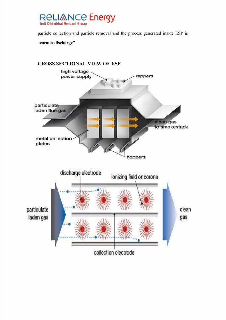
>. Eectrostatic Preci8itator /E&P19
Wor6ing Princi8e9
!he principle upon +hich an electrostatic precipitator operates are that the
dust laden gases pass into a chamber +here the individual particles of dust are
given an electric charge by absorption of free ions from a high voltage .
ioniDing field.
!he E#" utiliDes electrostatic forces to separate ash particles from the flue
gas to be cleaned. , very high efficiency (.3?) Electrostatic "recipitator is used
to collect fly ash generated. !he fly ash emission +ill be +ithin limits even +ith
one out of the six fields out of services.
E#" utiliDes the force acting on electrically charged particles in the presence
of in an electric field to effect the separations of the solid or li*uid particles from
the gas steam. 1arious configuration of E#" are corona effect particle charging
47
8/11/2019 Report of Thermal Power Plant
http://slidepdf.com/reader/full/report-of-thermal-power-plant 48/92
particle collection and particle removal and the process generated inside E#" is
Scorona dischargeD
CRO&& &ECTIONAL %IEW O7 E&P
48
8/11/2019 Report of Thermal Power Plant
http://slidepdf.com/reader/full/report-of-thermal-power-plant 49/92
,.AIR PREHEATER9
,ir "reheater is an important boiler auxiliary +hich primarily pre heats the
combustion air for rapid and efficient combustion in the furnace.
,ir "reheater recovers the +aste heat from the outgoing flue gas of the
boiler and transfer the same to combustion area.
8urther the air preheater may also be used for heating the air to dry the coal
in pulveriDing plant.
0.0 T$RBINE
Introduction9
#team turbine is the heart of the "o+er "lant +hich is a rotating machine
+hich converts heat energy of steam to mechanical energy.
#team turbines are of different capacities from 5< '0 to <44 '0. !he design
material and auxiliaries depend on the capacity of the system (!urbine)
#team turbines of t+o type designs such as
LMW * &o=iet Russian 3ade /Leningrad Meta 4or6s1
2W$ * "er3an 3ade /2raft Wor6s $nion1
49

8/11/2019 Report of Thermal Power Plant
http://slidepdf.com/reader/full/report-of-thermal-power-plant 50/92
In ;#E# eneration ivision (.!.".#.) @0/ design made of 7<4 '0 turbines is
used.
Wor6ing Princi8es9*
!he blades are attached to the turbine rotor. !he rapidly moving particles of
steam issuing from the noDDle enter the blade. ,s the blades are curved the
direction of motion of these particles of steam is changed.
;lades are designed in such a +ay that steam is made to glide upon and do
not get bombarded on the blade. ,s steam moves over the blades direction
is continuously changing and centrifugal pressure is exerted on the blade.
!he total motive force acting on the blades is the resultant of all the
centrifugal forces plus the change of momentum. !his causes the
rotational motion of blades.
&tea3 Tur#ine9*
!he turbine is condensing tandem compounded horiDontal reheat type single
shaft machine. It has separate high pressure ($") intermediate pressure (I") and
lo+ pressure (L") parts. !he $" and I" parts are single flo+ cylinder and L" part is
double flo+ cylinder. ue to steam turbine rotates and its energy is given to the
50

8/11/2019 Report of Thermal Power Plant
http://slidepdf.com/reader/full/report-of-thermal-power-plant 51/92
generator +hich produces electricity. !he turbine rotors are rigidly coupled +ith
each other and +ith generator rotor.
a. High Pressure Tur#ine /HPT19*
45 impulse stage
5C Reaction #tages
%uter casing is barrel
Inner casing axially split
#ingle flo+
,fter the super heater steam comes in to $"! here the steam expands and
steam does the +ork. ,fter this the temperature and pressure of steam
decreases. !hen it goes to the reheater to increase the pressure and temperature
through the cold reheat line (R$). !he R$ is provided +ith a non return
valve to prevent the back flo+ steam.
Para3eters 9*
5. Inlet pressure 53<-5<4 kgFcm7
7. Inlet temperature <34%
51
8/11/2019 Report of Thermal Power Plant
http://slidepdf.com/reader/full/report-of-thermal-power-plant 52/92
A. %utlet pressure 34kgFcm7
3. %utlet temperature A34%
#. Inter3ediate Pressure Tur#ine /IPT1 9
#ingle flo+ type
5> reaction stages
ouble casing ;oth ,xially #plit
Inner casing is axially split and carries guide blades
#team comes from the reheater +here the pressure and temperature are
increased. $ear the steam is allo+ed to expand and heat energy is converted into
mechanical energy. 8rom here the steam is lead to the L"! from the I"! exhaust
duct.
Para3eters 9*
+. Inlet pressure AC-A kgFcm7
0. Inlet temperature <34%
>. %utlet pressure >->.< kgFcm7
,. %utlet temperature A34%
52

8/11/2019 Report of Thermal Power Plant
http://slidepdf.com/reader/full/report-of-thermal-power-plant 53/92
c. Lo4 Pressure Tur#ine /LPT19
ouble flo+ type.
C reaction stages per flo+
asings2 - three casings. ,ll are axially split.
Inner casing carries five guide blades.
'iddle casing carries other three guide blades
Last three stages of L" rotor have t+isted blades. ,bove blade design
features reduces the relative velocity bet+een the droplets and the leading edges of
the moving blades resulting into less +ear and tear. 8irst five blades +ork in
superheated region and rest three in +et region. $o+ever the leading edges of the
final stage rotor blades are flame hardened to give protection against erosion.
BLA)E& O7 T$RBINE9
+. I38use T!8e9
In impulse turbine steam is expanded (i.e. pressure is reduced) in fixed
noDDles In impulse type of turbine pressure drop occurs in noDDles only not in
moving blades.
53

8/11/2019 Report of Thermal Power Plant
http://slidepdf.com/reader/full/report-of-thermal-power-plant 54/92
0 I38uses * Reaction T!8e9
In reaction type of turbine pressure is reduced in both fixed and moving
blades. !hey act like noDDles and are of same shape .0ork is done by the impulse
effect due to the reversal of direction of the high velocity steam plus a reaction
effect due to the expansion of steam through the moving blades
In ;#E# one impulse and other reaction blades turbine are used.
T$RBINE COMPONENT&9 *
!he various turbine components are
+1 Casing
01 Rotors
>1 Bading
,1 Turning gear
;1 Bearings
+. Casing9*
54

8/11/2019 Report of Thermal Power Plant
http://slidepdf.com/reader/full/report-of-thermal-power-plant 55/92
asing is a pressure vessel +hich must be capable of +ith- standing
maximum +orking pressure and temp. enerally casing is of ;,RREL type of
casing single F double.
!he +orking pressure aspects demand thicker and thicker casing and the
temperature aspects demands thinner and thinner casing. #o turbine casings are so
designed to take care of both pressure and temperature. #o three types of turbine
casing are there --
5. #ingle shell casing.
7. ouble (multiple) shell casing
A. ;arrel type of casing.
01 Rotors9*
Rotors are Bust like a shaft of machine. !he rotor used in .!.".# is Integral rotor
INTER"RAL T'PE O7 ROTOR9*
In this type of rotor in +hich +heels and shaft formed from one solid forging.
!he +hole rotor being one complete piece of metal
>1 Bades9-
!hese are most important components of the turbine. !hese are responsible
for main function of turbine.
55

8/11/2019 Report of Thermal Power Plant
http://slidepdf.com/reader/full/report-of-thermal-power-plant 56/92
, blade has A main parts
5. ,erofoil - It is +orking part of the blade.
7. Root - It is the portion of blade +hich is fixed +ith rotor of casing.
A. #hroud - It is riveted to main blade (but blade may be +ithout #hroud
,1 Turning "ear /Barring "ear19*
!urning gear is provided to rotate turbine shafts slo+ly during the pre run up
operation and after shutdo+n to prevent uneven heating or cooling of the shafts.
!his uneven cooling or heating +ill lead to bending and misalignment of the shaft.
/se of turning gear during starting eliminates of admitting suddenly a large
flo+ of steam to rotate turbine from rest. !o give lubrication to bearing and to
provide circulation of air +ithin the casing (L"!) after shutdo+n. #peed of !.. is
+ell chosen.
;1 Bearing of tur#ine shafts9*
56

8/11/2019 Report of Thermal Power Plant
http://slidepdf.com/reader/full/report-of-thermal-power-plant 57/92
!hese are seven bearings used in turbine. !he $" rotor is supported by t+o
bearings a double +edge Bournal bearing of the front end of the turbine and thrust
bearing directly adBacent to the coupling +ith the I.".rotor.
!he combined Bournal and thrust bearing incorporate a self adBusting
double +edge Bournal bearing and a thrust bearing +hich takes up residual thrust
from both directions. !he I.". & L.". rotors have a Bournal bearing each at end of
the shaft. !he Bournal bearing of I" & L" rotors are measured by thermocouple in
the lo+er shell directly under the +hite metal lining. !he temperature of the thrust
bearing is measured in t+o thrust pads on each side.
!he axial position of I" cylinder is also liked at the casing guide on rear end
of $" I" pedestals. !he expansion of I" cylinder takes place from $" & I" pedestal
to+ards generator.
T$RBINE "O%ERNIN" &'&TEM9
"o+er #tation !urbines are constant speed machines. In our country these
are supposed to rotate al+ays at a speed or A444 revolutions per minute (+ith in a
small band of fluctuations on either side) to enable the coupled generator to
produce electricity at <4$D fre*uency.
!he main purpose of governor is to maintain this desired speed of turbine
during fluctuation of load on the generator by varying steam input to the turbine.
57
8/11/2019 Report of Thermal Power Plant
http://slidepdf.com/reader/full/report-of-thermal-power-plant 58/92
!he governing system in addition to ensuring the falling load--speed
haracteristic of the turbine (i.e. a characteristic of falling output po+er +ith
raising shaft speed above nominal value) also ensures the follo+ing functions2
!he run of the turbine from rest to rated speed and synchroniDing +ith the
grid.
'eeting the system load variation in a predetermined manner +hen running
in parallel +ith other machines.
"rotecting the machines by reducing the load or shutting of completely in
abnormal and emergency situations.
T$RBINE A$?ILIARIE&2
!o facilitate proper functioning of turbine the auxiliaries are arranged at
different locations keeping in vie+ the easy installation proper operation and
maintenance and technical re*uirements.
A1 Condenser9
!he condensers used in !"# are surface condensers. In this type of
condensers condensation takes place on the outer surface of the tubes +hich are
cooled by sea+ater flo+ing through them.
58

8/11/2019 Report of Thermal Power Plant
http://slidepdf.com/reader/full/report-of-thermal-power-plant 59/92
!he function of condenser is2
ondenser condenses the steam exhaust from L" turbine by producing
vacuum in the condenser in order to increase the heat drop and increase the
efficiency of turbine by re-using the condensate.
!he cooling agent is sea +ater +hich is pumped by ooling 0ater "umps.
!he sea +ater is cleaned in debris filter and then it is taken to condenser through
t+o passes. $ence the condenser in !"# is a double pass single flo+ condenser.
!he pipes in the condenser are !itanium cladded. !hese tubes are half degree
inclined for self draining during tripping of ooling 0ater "umps. !he tubes are
expanded in main tube plates and are supported by support tube plates at
intermittent points to prevent sagging and to curb flo+ induced vibrations. !he
condenser is supported on springs to take the load variations +hen the condenser is
full and +hen the condenser is empty. !he 1acuum "ump creates vacuum in
ondenser and extracts all non-condensable gases to increase the steam inlet
in condenser.
&8ecifications9
5. 'ake ;$EL $ard+are
7. !ype #urface type
A. esign inlet temp AA
59

8/11/2019 Report of Thermal Power Plant
http://slidepdf.com/reader/full/report-of-thermal-power-plant 60/92
3. .0. flo+ per pass 5444tonesFhr
<. .0. temperature rise >.5
6. !ube material !itanium
>. o of passes 7
C. #urface area 5363Am7
. o of tubes 5>AAC
54. #iDe of tubes 77.77< x 4.>557 x 57744mm
B1 Condensate Etraction Pu389
ondensate extraction pump are five stages vertical double entry (at first
stage) centrifugal pumps. !hey are generally re*uired to operate on minimum et
"ositive #uction $ead ("#$). , vent line connects the hot +ell from +here the
E" takes the suction +ith condenser. !here should not be any temperature rise
here
&8ecifications9
5. 'ake ;$EL $yderabad7. o per unit 7
A. o of stages <
3. 8lo+ >>4mAFhr
<. Efficiency C7?
60

8/11/2019 Report of Thermal Power Plant
http://slidepdf.com/reader/full/report-of-thermal-power-plant 61/92
6. 'otor etails
>. Rating 6<4 k0
C. #peed 53C< rpm
. Rated current >5.7 amp
C1 Lo4 Pressure Heaters9
!he type of L" heaters used in !"# is of horiDontal /-tube surface type of
feed +ater heater +hich are three in no +hich t+o passes per heater.
;affles are provided to ensure that the steam is directed across the tubes.
!he upper section of the *uadrant of the tube nest +hich carries the condensate in
its last pass through the heater is totally enclosed by vertical baffles so forming a
flashed-steam drain cooler section of the heater.
!he three L" heaters L"$-5 L"$-7 L"$-A extractions are taken from the
L" turbine and hence this type of system is called regenerative feed heating
system.
8or L"$-5 bleed steam is taken from L" turbine stage >.L"$-7 receives
steam from L" turbine stage <. L"$-A receives steam from L" turbine stage
A.
!he drain outlet of L"$-A enters drain inlet of L"$-7. !he drain outlet of
L"$7 is given to drain inlet of L"$-5. L"$-5 is located at the neck of the
61

8/11/2019 Report of Thermal Power Plant
http://slidepdf.com/reader/full/report-of-thermal-power-plant 62/92
condenser to reduce floor space. ,ir vents are provided through +hich non-
condensable gases pass out to the condenser +here these gases are sucked
by the 1acuum "ump.
!hus the main purpose of L" heaters to preheat the condensate before
entering the boiler thereby is increasing the efficiency of the plant
)1 %acuu3 Pu389
!here are t+o vacuum pumps per unit. !he function of the vacuum is to absorb
the gases and air bubbles and to create vacuum in condenser
&8ecifications9
5. umber of pumps2 7
7. #tages2 7
A. #peed2 <44 rpm
3. ischarge "ressure2 5.44A kgFs*uare cm
E1 )eaerator9
62
8/11/2019 Report of Thermal Power Plant
http://slidepdf.com/reader/full/report-of-thermal-power-plant 63/92
!he pressure of certain gases like oxygen carbon dioxide and ammonia
dissolved in +ater is harmful because of their corrosive attacks on metals
particularly at elevated temperatures. !hus to prevent internal corrosion the feed
+ater should be free as far as possible of all dissolved gases especially oxygen.
7eed Water &!ste39
!he main e*uipments coming under this system are2
a1 Boier 7eed Pu38 &et9
;oiler feed pump (;8") is a multi stage pump provided for pumping
8eed +ater to economiDer. In !"# t+o ;8" pumps are provided for one unit.
Inlet of ;8" comes from deaerator +hich is located at re*uired head. !he pumped
+ater then goes to high pressure heater ($"$) and from there it goes to boiler
drum.
!hese pumps are barrel casing three stage cartridge pumps. !he cartridge (pump-
barrel) includes all pump internals +ith shaft impellers diffusers shaft seals
bearing housings and pumps half coupling.
The 3ain ee3ents of B7P set are9
63

8/11/2019 Report of Thermal Power Plant
http://slidepdf.com/reader/full/report-of-thermal-power-plant 64/92
+. Booster Pu38.
0. Boier 7eed Pu38.
>. H!drauic Cou8ing
+. Booster Pu389
)escri8tion9*
!he booster pump is a single stage horiDontal axially split casing type having
double suction and single discharge. !he pump shaft is sealed at driving rotor
assembly is supported by plain +hite metal Bournal bearing and
axially located by double thrust bearing. !he casing is made of cast steel.
Importance2
!he main function of booster pump is to aid the safe +orking of ;8". It
maintains the re*uired "#$ and thus the lo+er deaerator height. ;y the use of
booster pump in the main pump suction line the positive suction pressure can be
achieved +hich removes the possibility of cavitations.
NP&H is an acronym for Net Positi=e &uction Head. It sho+s the difference in
any cross-section of a generic hydraulic circuit bet+een the pressure and the li*uid
vapor pressure in that section.
64
8/11/2019 Report of Thermal Power Plant
http://slidepdf.com/reader/full/report-of-thermal-power-plant 65/92
"#$ is an important parameter to be taken into account +hen designing a
circuit 2 +henever the li*uid stagnation pressure drops belo+ the vapor pressure
li*uid boiling occurs and the final effect +ill be cavitation2 vapor bubbles may
reduce or stop the li*uid flo+. entrifugal pumps are particularly vulnerable
+hereas positive displacement pumps are less affected by cavitations as they are
better able to pump t+o-phase flo+ (the mixture of gas and li*uid) ho+ever the
resultant flo+ rate of the pump +ill be diminished because of the gas
volumetrically displacing a disproportion of li*uid.
&8ecification9*
!ype fa 5b ><
#uction >.> kgFcm7
ischarge pressure 7<.3 kgFcm7
"o+er re*uired 6>4 k0
0. Boier 7eed Pu389
!he feed +ater +ith the given operating temperature flo+s to the pump under
a certain "#$. !he +ater then passes through the suction branch into the intake
spiral and from here it is directed to the first impeller. ,fter leaving through the
impeller it passes through the distributing passages of the diffuser +here it gets
certain pressure rise and flo+s over to guide vanes to the inlet of the next impeller.
!his process is caused by the centrifugal action of +ater. !his process repeats from
one stage to the other fill if passes through the last impeller and the end diffuser.
65
8/11/2019 Report of Thermal Power Plant
http://slidepdf.com/reader/full/report-of-thermal-power-plant 66/92
8/11/2019 Report of Thermal Power Plant
http://slidepdf.com/reader/full/report-of-thermal-power-plant 67/92
from the speed difference bet+een impeller and runner. !his speed difference is
called slip.
!he +orking compartment is charged continuously by a pump +hich delivers
oil from the sump belo+ coupling. !he oil level in the +orking compartment
determines the speed of the runner +heel and the oil level depends upon the radial
position of scoop tube located in scoop chamber.
71 High Pressure Heaters9
$igh "ressure $eaters are of horiDontal /-tube surface type. !here are t+o
$"$ $"$-< and $"$-6. $igh pressure heaters receive condensate from the
;oiler 8eed "ump.
$" $eaters consist of tubes made up of stainless steel. !hese tubes expand
into the main tube plates and are supported by support tube plates at intermittent
points to prevent any sagging of tubes.
$"$-< receives steam from I.". turbine 54th stage and $"$-6 receives
steam from cold reheat line. $" $eaters consist of air vents through +hich non-
condensable bases are passed to the flash tank. 8rom there these gases go to the
67

8/11/2019 Report of Thermal Power Plant
http://slidepdf.com/reader/full/report-of-thermal-power-plant 68/92
condenser +here the 1acuum "ump sucks them thus creating a clear path for
steam. !he drain outlet of $"$-6 is given to $"$-<.
"1 Tur#ine Lu#rication Oi &!ste39
!his system fulfils the follo+ing important functions2
a) "rovides a supply of oil to Bournal bearings to give an oil +edge as the shaft
rotates.
b) 'aintains the temperature of turbine bearings constant at the re*uired level.
c) "rovides a medium for hydraulically operating the governor gear and controlling
the steam admission valves.
d) "rovides for hydrogen cooled generators a sealing medium to prevent hydrogen
leaking out along the shaft.
H1 Centrifuge9
!he purifier is used for purification of turbine oil. It dra+s oil from the
turbine oil tank (or dirty oil tank located outside turbine building) through a oil
pump. ,fter removing any +ater and entrained solid matter the clean oil is
returned to the oil tank (or pure oil tank).
!he entrifuge can perform the follo+ing t+o 8unctions2
68
8/11/2019 Report of Thermal Power Plant
http://slidepdf.com/reader/full/report-of-thermal-power-plant 69/92
5. Carification2 , li*uid (oil) - #ludge separation in +hich the machine is used
for separating of particles normally solids.
7. Purification 2 Li*uid (oil) - li*uid (+ater) separation in +hich the machine is
used for separating t+o intermixed li*uids +hich are insoluble in each other and
have different specific gravities solids +ith specific gravities higher than those of
the li*uids that can be separated off at the same time.
Princi8e of o8eration9
!he mixer of dirty oil +ater and solids impurities flo+ through the inlet
connection of the centrifuge hood and through the ports in the +alls of the inlet
pipe into the space bet+een the hub of the bo+l and the bore of the distributor. !he
mixer flo+s through holes in the conical base of the distributor and the discs to the
inner spaces bet+een the revolving disc +here the +ater and the solids are thro+n
out+ards by the centrifugal force and so are separated from the oil.
I1 )e#ris 7iter9
ebris such as shells sticks stones and plastic are a common cause of
failure in condenser. Improvements in primary screening +ould only lead to a
partial solution. It +ould only solve the problem of debris such from 0 pump
house. #econdary screening as close as possible to inlet +ater box is fulfilled by
ebris 8ilter.
69
8/11/2019 Report of Thermal Power Plant
http://slidepdf.com/reader/full/report-of-thermal-power-plant 70/92
!he internal construction and design is based on cooling +ater flo+ cooling
+ater inlet pressure siDe type and *uantity of debris. !he debris in cooling +ater
is collected at inner surface of 1-shaped screen housed inside the filter. ,
ifferential "ressure 'easuring #ystem ("'#) indicates the level of debris
fouling on filter screen across the screen +hen it reaches the preset limit the "'#
initiates the debris removal operation.
!he debris accumulated on the inside surface is removed by extraction
assembly +hich guides the debris along the basket into the debris discharge pipe
connected to main cooling +ater outlet pipe. !he filter incorporates a high-pressure
+ater-inBecting arm +hich is run by the 8lushing "ump.
O77&ITE A$?ILLIAR' $NIT& ARE9
70
8/11/2019 Report of Thermal Power Plant
http://slidepdf.com/reader/full/report-of-thermal-power-plant 71/92
+. Ash handing 8u38 house.
0. Coa handing unit.
>. C.W Pu38 house.
,. Water 8retreat3ent 8ant.
;. Water de3ineraiation 8ant.
A&H HAN)LIN" P$MP HO$&E
!he ash handling system of !"# is of +et and dry type. !he +et ash
handling system consists of bottom ash evacuation. ,sh disposal piping and pump
house. !he bottom ash collected in bottom ash hopper and evacuated once in shift.
!he bottom ash is crushed in clinker grinder and conveyed to the main slurry sump
by means of hydro-eBector. !he bottom ash evacuated at the rate of 574mtFhrs.
!he fly ash is collected in ,"$ /! E#" E%%'I#ER hoppers. !heash is evacuated by feeder eBector and conveyed to the intermediate sump by sluice
+ay trenches. !he ash from intermediate sump is pumped to the main slurry pump.
!he fly ash is evacuated at the rate of 564mtFhrs.
!he ash from main slurry sump is further disposed in ash pond by 3 streams
of slurry pumps +hich are connected to t+o no of basalt disposal pipe lines of
7@m each.
COAR&E A&H &'&TEM
71

8/11/2019 Report of Thermal Power Plant
http://slidepdf.com/reader/full/report-of-thermal-power-plant 72/92
,sh collected in 57 no=s of EconomiDers FuctF,"$ hoppers +ill be
removed once in a shift. !he changeover of hopper group is affected through either
timers or lo+ level s+itches +hichever events are earlier. Each coarse ash hopper
is provided +ith one number manually operated hopper isolation valve
pneumatically operated valve expansion Boint and feeder eBector. !he pressuriDed
+ater feed to the feeder eBector mixes +ith the free falling ash and the resultant
slurry +ill be conveyed into slurry trench connected to intermediate 8E slurry
sump.
7L' A&H HAN)LIN" &'&TEM
8orty-eight electrostatic precipitator hoppers four E#" hoppers constitute one
group. !hus there are 57 groups of fly ash hoppers. Each group of fly ash hoppers
is operated one by one in se*uence. ,ll the hoppers of one group openFclose
simultaneously. !he changeover of hopper group is affected through either timers
or lo+ level s+itches +hichever event is earlier.
Each fly ash hopper is provided +ith one no manually operated hopper
isolation valve pneumatically operated fly ash valve expansion Boint and feeder
eBector. !he feeder eBector +hen feed +ith pressuriDed +ater serves to mix the free
falling fly ash +ith +ater and discharge the resultant slurry into the slopping trench
provided underneath +hich is connected to main slurry trench. !he fly ash slurry
extracted from various hoppers flo+s do+n through main slurry trench. !he fly ash
slurry extracted from various hoppers flo+s do+n through main slurry trench
aided by high-pressure +ater Bets to the intermediate fly ash slurry sump. 8rom
there the slurry +ill be transported to the main slurry sump by means of one 8ly
ash slurry pump in unit-I and t+o fly ash pump in unit-II. Intermediate slurry sump
72

8/11/2019 Report of Thermal Power Plant
http://slidepdf.com/reader/full/report-of-thermal-power-plant 73/92
of both units +as interconnected by common trench. Each group of hopper has one
pneumatically operated valve in feeder eBector +ater line.
A&H )I&PO&AL &'&TEM
!he bottom ash coarse ash & 8ly ,sh led to common slurry pump sets &
disposal lines. 8our no=s of identical streams connected to t+o no=s of slurry
disposal lines. %ut of four streams provided single stream run continuously for
both units & the remaining three streams serve as standby. 'ake valve & line
flushing are provided in each compartment to enable the slurry disposal pumps to
run & flush the disposal pipelines. 1arious level s+itches provided in each of the
sump initiates highFlo+ level alarm protects the sump from dangerously lo+ level
& also controls the makeup valves.
,sh slurry sump +hich is common for both units is a R tank +ith four
compartment one for each of the pump stream. ,gitating noDDles provided in the
sumps keeps the solids in slurry in floating state. "neumatically operated suction &
discharge valve for each stream of pumps helps in isolation of the stream. isposal
piping has special E:9 coupling Boints to ensure ease in periodical rotation of the
pipes for uniform +ear.
R9 ,#$ #9#!E'
• !he fly ash collected at the E#" hoppers are gravity fed into individual
transmitter vessels provided belo+ each hopper • %n initiation of dry fly ash collection system the inlet valve opens and
allo+s the fly ash to be fed into the transmitter vessel for pre-determined
time after +hich the inlet valve closes.
73

8/11/2019 Report of Thermal Power Plant
http://slidepdf.com/reader/full/report-of-thermal-power-plant 74/92
• ,fter+ards the compressed air is allo+ed to flo+ into the transmitter vessel
by opening the air inlet valve.
•%nce the desired conveying pressure is reached inside the vessel the fly ashstorage silo through transport piping.
• !he conveying air is vented through the bag filters mounted on top of the
silo in order to limit the dust concentration in the vented air.
COAL HAN)LIN" $NIT
COAL
oal may be defined as that part of the Earth=s crust +hich has been formed as a
result of the accumulation of decayed plant remains million of years ago and its
subse*uent consolidation over the years by a complex series of chemical and
physical changes. oal is essentially carbon and is mainly used as a combustion
fuel.
T!8es of Coa9*
0e use the term TcoalT to describe a variety of fossiliDed plant materials but no
t+o coals are exactly alike. $eating value ash melting temperature sulfur and
other impurities mechanical strength and many other chemical and physical
properties must be considered +hen matching specific coals to a particular
application.
!he carbon content of coal supplies most of its heating value but other factors
also influence the amount of energy it contains per unit of +eight.
74

8/11/2019 Report of Thermal Power Plant
http://slidepdf.com/reader/full/report-of-thermal-power-plant 75/92
!here are four main types of coal and are arranged in increasing order of their
carbon content on moving do+n+ards2
Lignite
#ub- ;ituminous
;ituminous
,nthracite
COAL 7OR THERMAL POWER &TATION9
India is blessed +ith a very good reserve of non-coking coal. on coking
;ituminous or #ub ;ituminous oal is normally the basic fuel used for thermal
po+er generation. !o achieve economy of individual plant and also to ascertain the
efficiency of the generating e*uipments representative coal sampling is of prime
interest. 8urther coal prices are fixed as per the *uality of coal hence if the proper
vigilance is not given for the *uality of coal +hich are received then consumer
may suffer a substantial loss. $ence continuous monitoring of coal *uality is
essential.
ationalisation of collieries and introduction of modern e*uipments for coal
mining and loading has resulted into variation of coal *ualities even from singlemine.
COAL $&E) AT )AHAN$ THERMAL POWER &TATION
,) Indian oal
75

8/11/2019 Report of Thermal Power Plant
http://slidepdf.com/reader/full/report-of-thermal-power-plant 76/92
I) Ra+ oal
II) 0ashed oal (lean coal)
;) Imported oal
Coa testing is di=ided into > 8arts
I) #ampling
II) Reduction & preparation
III) ,nalysis
I1 &LIN" O7 COAL9 I# -3A6 J "art I J #ec- I2 563 Reaffirmed 7445
ra+ing of Indian oal samples at .!.".#. is carried out at t+o locations J
i) #ampling from running onveyor ;elt
ii) #ampling from Loaded 0agons
)ra4ing of I38orted Coa sa38es at ).T.P.&. is carried out at
Jett!.
i1 &a38ing fro3 Running Con=e!or Bet9 *
ollection of coal samples are carried out from onveyor ;elt 5, F 5; after
!ippler.
i) !he *uantity of coal to be dra+n approx. A44 to 344 kg per rake.
76
8/11/2019 Report of Thermal Power Plant
http://slidepdf.com/reader/full/report-of-thermal-power-plant 77/92
ii) #ample collection to be done +ith the help of a suitable scoop.
iii) !he increment shall be dra+n +ith the help of a scoop at regular intervals.
iv) Each increment shall be of A @g (approx.).
v) !he increments shall be collected from the center and left and right sides of the
belt along the same +idth.
vi) !he scoop shall s+eep the bottom of the conveyor.
vii) !he material collected from all the increments shall be mixed together and
shall constitute a gross sample.
viii) !his gross sample shall be used for *uality analysis.
ix) #eparate unexposed sample shall be dra+n for the determination of !otal
'oisture.
x) !he *uantity of the above sample shall be <4 @g (approx.)
ii1 &a38ing fro3 Loaded Wagons9*
oal rake contains <> to <C nos. of +agons.
i) !he *uantity of coal to be dra+n approx. A44 to 344 kg per rake.
ii) , minimum of 7< ? of the +agons shall be selected at random basis for
collection of coal sample.
iii) %ne point shall be located at random on the coal surface of each of the selected
+agons.
77
8/11/2019 Report of Thermal Power Plant
http://slidepdf.com/reader/full/report-of-thermal-power-plant 78/92

8/11/2019 Report of Thermal Power Plant
http://slidepdf.com/reader/full/report-of-thermal-power-plant 79/92
vii) !his gross sample shall be used for *uality analysis.
viii) #eparate unexposed sample shall be dra+n for the determination of !otal
'oisture.
ix) !he *uantity of the above sample shall be <4 @g (approx.)
II1 RE)$CTION PREPARATION9
!he gross sample (A44-344 @g) for *uality analysis shall be crushed to 57.< mm
and then to A.A< mm siDe by Lab. Ha+ rusher. 8urther reduction of *uantity up to
7.4 @g by using the techni*ue coning & *uartering after air drying. rind the
above material to pass 757 neither micro nor >7 mesh siDes by Lab. "ulveriser.
!his sample shall be used for S"roximate ,nalysisU.
!he gross sample (<4 @g) for !otal 'oisture analysis shall be crushed to57.< mm
by Lab. Ha+ rusher. 8urther around 5.4 kg sample shall be collected from abovesample & kept for air drying for 73 hrs for determination of surface moisture (O).
8urther this sample is crushed to 7.C4 mm siDe & heated at 54C V < eg. in Lab.
%ven for A $rs. 0eight loss isrecorded as W9=.
!otal moisture (?) O X 9 (5 J OF544)
!he coal +hich has been exposed to contact +ith +ater in the seam or in a
+ashery or coal +etted by rain may carry free or visible +ater. !his +ater plus the
moisture +ithin the material is referred to as !otal moisture.
III1 ANAL'&I& 9
oal samples can be analyDed by the follo+ing methods2-
79
8/11/2019 Report of Thermal Power Plant
http://slidepdf.com/reader/full/report-of-thermal-power-plant 80/92
,) "roximate ,nalysis I# -5A<4 J "art I J 5C3 Reaffirmed 7445
;) /ltimate ,nalysis I# -5A<4 J "art I1 J 5>3 Reaffirmed 7444
) ross alorific 1alue I# -5A<4 J "art II J2 5>4 Reaffirmed 7444
) $ard-rove rind ability Index ($I) I# -33AA 5> Reaffirmed 7444
A1 Proi3ate Ana!sis 9*
"roximate analysis is carried out on ,ir dry basis (,;)
"roximate analysis of coal means determination of -
i) Inherent 'oisture (I. '.)
ii) ,sh ontent
iii) 1olatile 'atter (1. '.)
iv) 8ixed arbon (8. .).
ANAL'&I& O7 COAL9
i1Inherent Moisture /I.M19
'oisture in the coal sample after it has attained approx. e*uilibrium +ith air to
+hich it is exposed or it is the moisture in coal +hich has been air J dried under
the laboratory atmospheric condition prior to analysis.
,pprox. 5.4 gm of pulverised laboratory sample Is dried in Lab. %ven at 54C V
< eg. for A $rs. Loss in +eight is reported as Inherent 'oisture.
80

8/11/2019 Report of Thermal Power Plant
http://slidepdf.com/reader/full/report-of-thermal-power-plant 81/92
ii1 Ash9
It is the residue of mineral matter obtained by incinerating coal under define
conditions. In simple term ash is incombustible matter present in the coal.
,pprox. 5.4 gm of Laboratory sample is heated at C5< V 5< deg. in Lab.
8urnace for 5.< to 7.4 $rs and the residue left behind is reported as ,sh content.
iii1 %oatie Matter /%. M.19
1olatile matters are the volatile products of thermal decomposition of coal.
,ctually it is the loss in +eight of moisture free coal.
,pprox. 5.4 gm of lab #ample is heated at 44 V 54 eg. in Lab. 8urnace for
>.4 mins. !he +eight loss minus inherent moisture is reported as 1olatile 'atter.
i=1 7ied Car#on /7. C.19
It is the residue of carbon left after deduction of 1. '. ,sh & 'oisture
8. . 544 J (,sh X 1. '. X I. '.)
B1 $ti3ate Ana!sis9*
;y ultimate analysis +e mean ultimate composition of coal in terms of percent
arbon $ydrogen itrogen #ulphur and %xygen.
arbon & $ydrogen2 arbon & hydrogen in coal directly contributes
to+ards the alorific 1alue of coal. $igher the percent of arbon &
$ydrogen better is the *uality of coal and higher is its calorific value.
itrogen2 It is present in small *uantity say nearly 5-7? and does not
contribute any /seful value to coal.
81
8/11/2019 Report of Thermal Power Plant
http://slidepdf.com/reader/full/report-of-thermal-power-plant 82/92
%xygen 2 !he lo+er the oxygen content the more is the maturity of the coal
and greater is its
alorific 1alue. If %7 content is more the capacity of coal to hold moisture
increases and the caking po+er increases.
/ltimate analysis is determined by using the formulae.
? 4.> 8. X 4.> (1.' J 4.5 ,) J 4.6 I.'
? $ 4.4A6 8. X 4.45 (1.' J 4.5 ,) J 4.4< I.'
? 7.5 - (4.457 x 1.')
? % 544 J (? X ? $ X ? X ? # X ? ,#$ X ? I.')
#ulphur2-#ulphur in coal is determined gravimetrically by the Eschka=s
'ethod.
!he sample of coal is heated in intimate contact +ith Eschka=s mixture in anoxidiDing atmosphere to remove combustible matter and to convert the sulphur to
sulphate. !his is then extracted and determined by gravimetric method by
precipitation as barium sulphate +ith barium chloride.
#ulphur present in coal contributes to heating value of coal but its combustion
products (#%7 & #%A ) have corrosive effects on e*uipments also harmful for
environment. !herefore coal +hich contains lo+ sulphur is preferred.
Esch6aFs 3iture* A 3iture of 3agnesiu3 and dried sodiu3 car#onateG used
as a reagent for deter3ining su8hur in coa or co6e.
82

8/11/2019 Report of Thermal Power Plant
http://slidepdf.com/reader/full/report-of-thermal-power-plant 83/92
C1 "ross Caorific %aue2
!he calorific value of a sample determined by burning the sample in a controlled
environment. !he heat released by combustion is proportional to the calorific value
of the substance. alorific value is measured by an instrument called S;%';
,L%RI'E!ERU is measured in @cal F@g or al F gm or ;tu F lb i.e. ;ritish
thermal unit per pound.
"ross caorific =aue is e38o!ed to find out(
5) !hermal efficiency of combustion.
7) oal consumption per @0$.
A) $eat value of coal.
3) $ard rove rind ability Index ($I)2 I# 33AA2 5> (,mended in 7444)
$I indicates hardness property of coal. 0hich indicates its easiness to+ards
pulveriDation of coalY
It also reflects the life and efficiency of the pulveriDing e*uipments. Lo+er $I
means difficulty in pulveriDation. 1ery high $I is also not +anted as it +ill start
giving fines right from the mines. oal fines are very difficult in handling
particularly in rainy season as it forms a very sticky mass.
<4 grams of coal sample of the siDe 4.6 mm to 5.7 mm is grinded in $I
machine for 64 rotations. !he grinded material is passed through 744 ,#!'
mesh. !he +eight of material passed is taken as W0=
83

8/11/2019 Report of Thermal Power Plant
http://slidepdf.com/reader/full/report-of-thermal-power-plant 84/92
REPORTIN" O7 ANAL'&I& RE&$LT&
• In the actual prevailing conditions there may be variation in the moisture
ontent of coal +hich +ill affect the end *uality. It is advisable to procure and
analyse the coal on W,s Received ;asis =.
• !he analysis of coal is being carried out under laboratory condition. ,ll the
results obtained are on W,ir ried ;asis =.
• !he moisture correction is being applied for converting ,; results in to
,R;.
Pro#e3s Associated 4ith
+1 Moisture of coa
Loss of ;oiler Efficiency
Reduce pulveriDing capacity
8orms reducing atmosphere
($7% X $7 X % )
Reduce the temperature of primary air leading to mill clogging up.
8luctuating moisture tends to cause mill fire
01 Ash content
$igh ash reduce flame stability
#lag & clinkering problem
84

8/11/2019 Report of Thermal Power Plant
http://slidepdf.com/reader/full/report-of-thermal-power-plant 85/92
!ube deposit
ifficulty in ,sh handling and dumping
Reduce life of 'ill components
Erosion in boiler tubes and ash slurry pipes
>1 %oatie Matter
Lo+ 1' coal difficult to burn and less reactive
$igh 1' coal easy to burn and more reactive
$igh 1' coal catch fire in coal yard due to atmospheric temperature
,1 7ied Car#on
1 is dependent on 8 in oal
Lo+er the 8 lo+er is 1 higher is the coal consumption.
;1 &u8hur
8ormation of #%x
$ot corrosion on boiler tubes
85
8/11/2019 Report of Thermal Power Plant
http://slidepdf.com/reader/full/report-of-thermal-power-plant 86/92
COOLIN" WATER P$MP HO$&E
!he cooling +ater pump house is situated on the sea shore of ,rabian sea
+hich is about 7-Akm a+ay from the main plant and the sea +ater is used for the
cooling of steam in the condenser +hich is delivered to the main plant using the
pipe lines.
,s the sea +ater comprises of the living organisms as +ell so if +e deliver
this uncleaned +ater to the main plant then these living organisms could stack thedelivery pipe lines so to prevent this chlorination is done of this +ater to kill those
living organisms and chlorination is done only in that *uantity so that "$ of the
+ater could also be maintained through this addition of chlorination the living
organisms died and are separated from +ater in the primary stage of filtration
through +hich the pump sucks the +ater from the sea.
!his pump house comprises of 3 no of pumps. Each pump is concrete volute fitted
and are mixed flo+ +ith vertical suction.7 pumps are used for the supply of
cooling +ater for cooling a single unit of condenser of 7<4'0 by supplying
7Z7>444 mA Fhr (the capacity of each pump is 7>444mAFhr supply of +ater).
!his +ater cools the steam in the condenser +hich came there from turbine and
converts it in the li*uid form thus forming a recycle process and this converted
+ater is again used for steam formation and approximately 4? of the steam is
converted into li*uid.
86
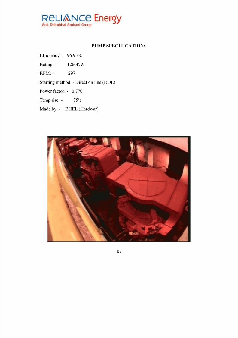
8/11/2019 Report of Thermal Power Plant
http://slidepdf.com/reader/full/report-of-thermal-power-plant 87/92
P$MP &PECI7ICATION9*
Efficiency2 - 6.<?
Rating2 - 5764@0
R"'2 - 7>
#tarting method2 - irect on line (%L)
"o+er factor2 - 4.>>4
!emp rise2 - ><4c
'ade by2 - ;$EL ($ard+ar)
87
8/11/2019 Report of Thermal Power Plant
http://slidepdf.com/reader/full/report-of-thermal-power-plant 88/92

8/11/2019 Report of Thermal Power Plant
http://slidepdf.com/reader/full/report-of-thermal-power-plant 89/92
,fter sand filtration the +ater is stored at a certain place and by doing chlorination
to certain part of it +ater is supplied for the use of drinking +ashing etc to the
colony.
,fter that rest of the +ater it transferred to the emineraliDation plant for its
further treatment
IMP$RITIE& IN WATER
)isso=ed "ases &us8ended I38urities Tota )isso=ed &oids
)ust )e#ries Cooids Cations /1 Anions /*1
Tur#idit! /NT$1 Caciu3 /Ca1 Choride /C1
Magnesiu3 / Mg1 &u8hate /&O,1
&odiu3 /Na1 &iica /&iO01
Nitrate /NO>1
Car#onate /CO>1
Bicar#onate/ HCO>1
Conducti=it! /& c31
The 3ain O#5ecti=es of Water Treat3ent in Po4er Pant9
5) "revention of scaling in boiler
7) "revention of corrosion in boiler.
A) "revention of steam F +ater contamination.
89

8/11/2019 Report of Thermal Power Plant
http://slidepdf.com/reader/full/report-of-thermal-power-plant 90/92
Basic structure of 4ater 8re treat3ent 8o4er 8ant
90

8/11/2019 Report of Thermal Power Plant
http://slidepdf.com/reader/full/report-of-thermal-power-plant 91/92

8/11/2019 Report of Thermal Power Plant
http://slidepdf.com/reader/full/report-of-thermal-power-plant 92/92
7ig*+.interna of de3ineraiation 8ant
PLANT MAINTAINENCE
5.!he tanks are cleaned thoroughly during the maintenance time period of the
plant.
7 In case of failure of any of the tank due to any reason then there is the presence