report on aircraft serious incident - skybrary.aero
TRANSCRIPT
Report on aircraft serious incident
Case no: M-00513/AIG-04 Date: 26. February 2013 Location: Keflavik Airport (BIKF) Description: Uncommanded left roll during final approach
Investigation per Icelandic Law on Transportation Accident Investigation, No. 18/2013 shall
solely be used to determine the cause(s) and contributing factor(s) for transportation accidents
and incidents, but not determine or divide blame or responsibility, to prevent further
occurrences of similar cause(s). This report shall not be used as evidence in court and it shall
not be used to determine or divide blame or responsibility.
2
Contents
Contents .................................................................................................................................... 2
Synopsis .................................................................................................................................... 3
1 Factual information ............................................................................................................ 4
1.1 History of the flight ..................................................................................................... 5
1.2 Injuries to persons ................................................................................................... 12
1.3 Damage to aircraft ................................................................................................... 12
1.4 Other damages ........................................................................................................ 12
1.5 Personnel information .............................................................................................. 13
1.6 Aircraft Information .................................................................................................. 13
1.7 Meteorological information ....................................................................................... 14
1.8 Aids to navigation .................................................................................................... 14
1.9 Communications ...................................................................................................... 14
1.10 Aerodrome information ............................................................................................ 14
1.11 Flight Recorders ...................................................................................................... 14
1.12 Wreckage and Impact information ........................................................................... 15
1.13 Medical and pathological information ...................................................................... 15
1.14 Fire ........................................................................................................................... 15
1.15 Survival aspects ....................................................................................................... 15
1.16 Test and research .................................................................................................... 15
1.16.1 Moog inspection of spoiler actuators ............................................................... 18
1.17 Organizational and management information.......................................................... 21
1.18 Additional information .............................................................................................. 21
1.19 Useful or effective investigation technique .............................................................. 22
2 Analysis ........................................................................................................................... 24
2.1 Flight operation ........................................................................................................ 24
2.2 Operational procedures ........................................................................................... 27
2.3 Air traffic control ....................................................................................................... 27
2.4 Communication ........................................................................................................ 28
2.5 Aircraft maintenance ................................................................................................ 28
2.6 Aircraft systems ....................................................................................................... 28
2.7 Actions already taken as a result of this incident..................................................... 29
3 Conclusion ....................................................................................................................... 30
3.1 Findings ................................................................................................................... 30
3.2 Causes ..................................................................................................................... 32
4 Safety Recommendations ............................................................................................... 33
3
Synopsis
Icelandair B757-200, TF-FIJ, was enroute to Keflavik Airport (BIKF), on a flight from
Copenhagen Airport (EKCH). At top of descent, the airplane’s right hydraulic system
failed when a hydraulic tube in the wheel well cracked. The flight crew performed the
necessary actions to prepare for landing with inoperative systems as a result of the
right hydraulic system failure.
At 22:26, during night, on a 7 NM final approach to RWY 20 at Keflavik Airport, when
the flaps had been fully deployed the airplane suddenly rolled to the left. The airplane’s
center autopilot was engaged. The roll was uncommanded and caused partial loss of
control. When the flight crew was trying to regain full control of the airplane, flap
overspeed occurred. Following the flap overspeed the airplane was pitched down. The
airplane’s speed continued to increase and the airplane started to descend rapidly.
This resulted in the flight crew declaring an emergency. The investigation revealed that
the flight crew had regained full control of the airplane 2 minutes and 42 seconds after
the uncommanded left roll. Three minutes and 22 seconds after the left roll and partial
loss of control, the flight crew contacted ATC1 and advised that they had regained full
control of the airplane and were ready to commence another approach to the airport.
At that time the airplane was located south of Straumsvík, near Hafnarfjörður.
The investigation of the data from the FDR revealed that there had been a latent spoiler
module failure present for the past 27 flights. Inspection of the spoiler system revealed
a latent failure in the actuator of spoiler #6, due to cracked Blocking and Thermal Relief
Valve Housing.
Full deployment of the flaps, with the right hydraulic system unpressurized and the
Blocking and Thermal Relief Valve Housing cracked, caused spoiler #6 to float. This
caused in asymmetrical lift between the left and the right wings, resulting in a rolling
moment to the left.
Several safety recommendations are issued.
1 Air Traffic Control
4
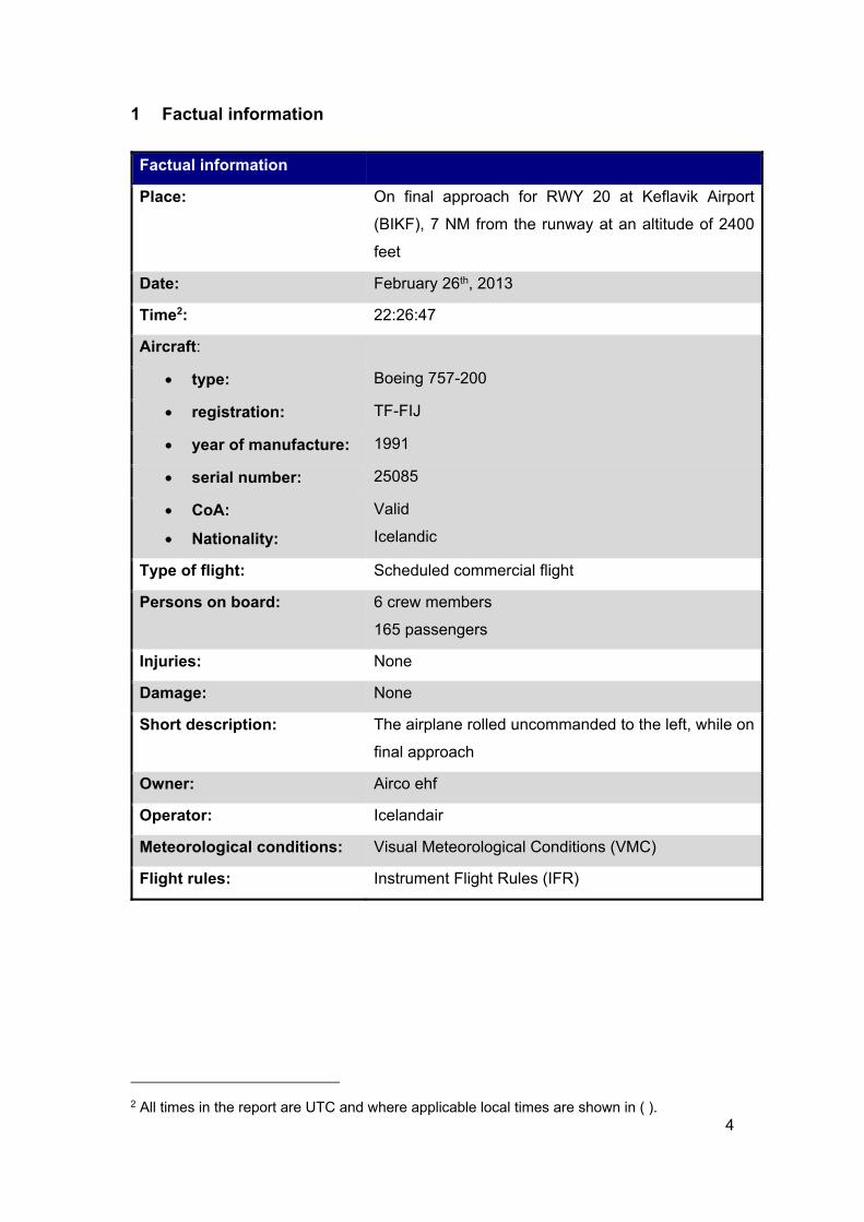
1 Factual information
Factual information
Place: On final approach for RWY 20 at Keflavik Airport
(BIKF), 7 NM from the runway at an altitude of 2400
feet
Date: February 26th, 2013
Time2: 22:26:47
Aircraft:
type: Boeing 757-200
registration: TF-FIJ
year of manufacture: 1991
serial number: 25085
CoA:
Nationality:
Valid
Icelandic
Type of flight: Scheduled commercial flight
Persons on board: 6 crew members
165 passengers
Injuries: None
Damage: None
Short description: The airplane rolled uncommanded to the left, while on
final approach
Owner: Airco ehf
Operator: Icelandair
Meteorological conditions: Visual Meteorological Conditions (VMC)
Flight rules: Instrument Flight Rules (IFR)
2 All times in the report are UTC and where applicable local times are shown in ( ).
5
1.1 History of the flight
On the evening of February 26th 2013 Icelandair B757-200 airplane, TF-FIJ, was
enroute to Keflavik Airport (BIKF), on a flight from Copenhagen Airport (EKCH).
The first officer was the pilot flying, as the commander had flown the previous
flight leg from Keflavik to Copenhagen. The airplane’s center autopilot was
engaged.
Shortly before top of descent, at 21:45 when at FL360, the fourth cabin
attendant3, located in back of the airplane, called the flight crew on the intercom
system. He reported that, about 5 minutes earlier, he started noticing, in the
center area of the airplane, a constant, steady bass like sound unlike anything
he had heard before in flight. The first officer scanned the instruments and did
not observe any indication of a problem. He advised that there were no
abnormalities on the flight crew’s instruments and asked the flight attendant if he
could distinguish from which side of the airplane this unusual sound was
emanating from. The cabin attendant replied that he could not locate the source
of the sound, it was all over he stated, but most noticeable in the wing area and
aft of that location. The flight crew discussed what the source of this abnormal
sound in the cabin could be, as there was no abnormal indication on the flight
deck displays. Shortly thereafter the senior cabin attendant entered the flight
deck and reported that she went to the aft cabin and also noticed the unusual
sound the fourth cabin attendant had previously reported.
At 21:52, when the flight crew was communicating with an ATC officer and about
to initiate descent4, the flight crew noticed the floor vibrating and the following
indication appearedon the EICAS monitor:
R HYD QTY
There was a problem with the right hydraulic quantity, so the flight crew consulted
the QRH5. While they were consulting the QRH, a second EICAS message
appeared:
3 The cabin attendants have a ranking of: Senior-, second-, third- and fourth cabin attendant 4 Top of descent 5 Quick Reference Handbook
6
R HYD SYS PRESS
The flight crew realized that they had lost the right hydraulic system and started
working the “Hydraulic Quantity” and the “Hydraulic System Pressure (R only)”
checklists from the QRH6.
The flight crew was aware that due to the RH hydraulic system failure, some
spoilers on each wing would be inoperative. They also discussed that according
to the QRH, because of the loss of the RH hydraulic system, the right autopilot,
right thrust reverser, the right stabilizer trim and the auto brake system would
also not be functioning. Finally they also discussed that this would affect the
landing distance, due to non-normal landing configuration, but because of the
length of the RWY at BIKF that would not be a factor. During descent the flight
crew tested the spoilers and found them to be performing poorly and the
following indication showed up on the EICAS monitor:
SPOILERS
The flight crew requested from ATC a vector to RWY 20 and to be established
early on the localizer. Until on final approach, the airplane was in IMC7. The
localizer was intercepted, at 2600 feet altitude about 7.8 NM from the runway.
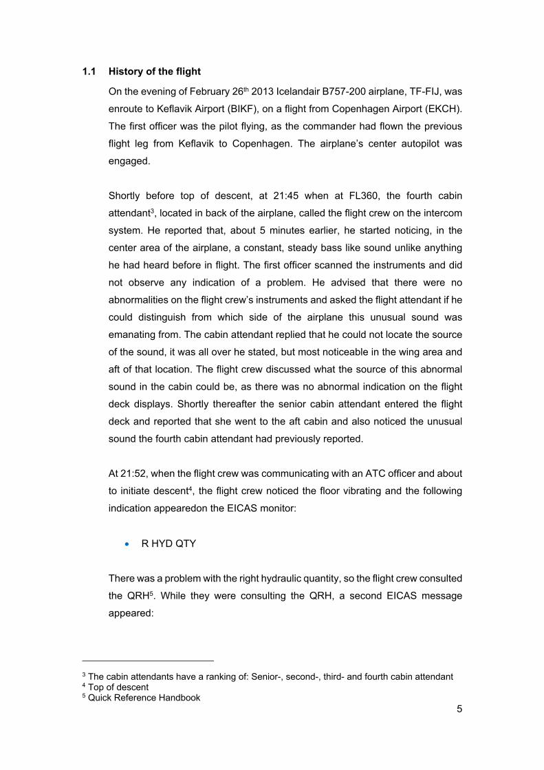
The flaps were extended and the landing gear selected down. At 22:26:47,
during night, when the flaps had reached the 30° position, the flying pilot [first
officer] noticed vibration and the airplane started an uncommanded roll to the
left. The airplane was at an altitude of 2400 feet and a distance of 7 NM from the
runway when this occurred. The flying pilot scanned the instruments, expecting
to see asymmetry indications on the EICAS, but there were none. The flying pilot
then noticed that according to the “trend vector” the airplane was beginning to
turn to the left. See Figure 1 for details.
6 Quick Reference Handbook, pages 13.2 and 13.10-13.11 7 Instrument Meteorological Conditions
7
Figure 1: The airplane (ICE213) starts to turn to the left (ATC radar)
According to the pilot flying, he had not managed to set the go-around altitude at
3000 feet as required by SOP8 when the upset occurred.
The flying pilot disengaged the autopilot and tried to correct the airplane’s
heading by steering full right. Initially there was no response to the pilot’s right
turn steering wheel input. No additional warning was indicated on the EICAS.
Five seconds after the upset9, the commander commanded a go-around. The
airplane continued its uncommanded left roll and reached its maximum left bank
angle of 34°, 8 seconds after the upset. The commander started to retract the
flaps. As the flaps started to retract from the 30° to the 20° position, about 20
seconds after the initial upset, the airplane bank angle decreased to 18°. When
the flaps were somewhere between 20° and 5° the pilot felt the airplane
responding to the right steering wheel input.
8 Standard Operating Procedures 9 To distingush between the right hydraulic failure at top of descent and the uncommanded turn on the final approach, the start of the uncommanded turn is called upset in the report
8
The Keflavik tower ATC officer contacted the flight crew 26 seconds after the
initial upset and requested a confirmation of continuation of the approach. The
flight crew replied that they were going around.
The airplane started to climb in its go-around mode and levelled off at 4000 feet
50 seconds after the upset. One minute after the upset the airplane was wings
level, on heading 135° and the computed airspeed was at 200 knots and
increasing. About six seconds later, when the flaps were still being retracted and
the flaps were in the 5° position the airplane exceeded the flap speed limit of 220
knots.
Following the flap overspeed the airplane was pitched down to descend down to
go-around altitude. The airplane’s speed continued to increase and the airplane
started to descend rapidly. The pilot flying was aware of high descent rate
developing, but did not immediately take the proper action to correct it. According
to the pilots they began to question and discuss their instruments at this time, as
the possible cause of the uncommanded roll.
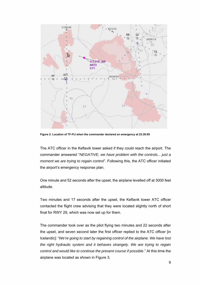
One minute and 21 seconds after the upset, at 22:28:09, following a descent rate
of about 3500 feet/min for few seconds and the pilot flying declaring that they
were descending too quickly, the commander declared an emergency to ATC.
At the same time flap retraction was stopped with the flaps in 1° flap position,
leaving the airplane in a flap overspeed condition. At this time the airplane was
located as shown in Figure 2.
9
Figure 2: Location of TF-FIJ when the commander declared an emergency at 22:28:09
The ATC officer in the Keflavik tower asked if they could reach the airport. The
commander answered “NEGATIVE, we have problem with the controls... just a
moment we are trying to regain control”. Following this, the ATC officer initiated
the airport’s emergency response plan.
One minute and 52 seconds after the upset, the airplane levelled off at 3000 feet
altitude.
Two minutes and 17 seconds after the upset, the Keflavik tower ATC officer
contacted the flight crew advising that they were located slightly north of short
final for RWY 29, which was now set up for them.
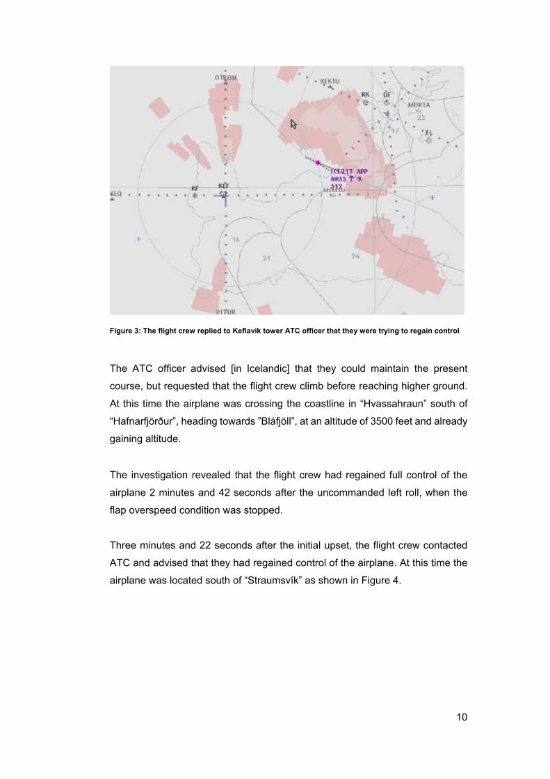
The commander took over as the pilot flying two minutes and 22 seconds after
the upset, and seven second later the first officer replied to the ATC officer [in
Icelandic]: “We’re going to start by regaining control of the airplane. We have lost
the right hydraulic system and it behaves strangely. We are trying to regain
control and would like to continue the present course if possible.” At this time the
airplane was located as shown in Figure 3.
10
Figure 3: The flight crew replied to Keflavik tower ATC officer that they were trying to regain control
The ATC officer advised [in Icelandic] that they could maintain the present
course, but requested that the flight crew climb before reaching higher ground.
At this time the airplane was crossing the coastline in “Hvassahraun” south of
“Hafnarfjörður”, heading towards ”Bláfjöll”, at an altitude of 3500 feet and already
gaining altitude.
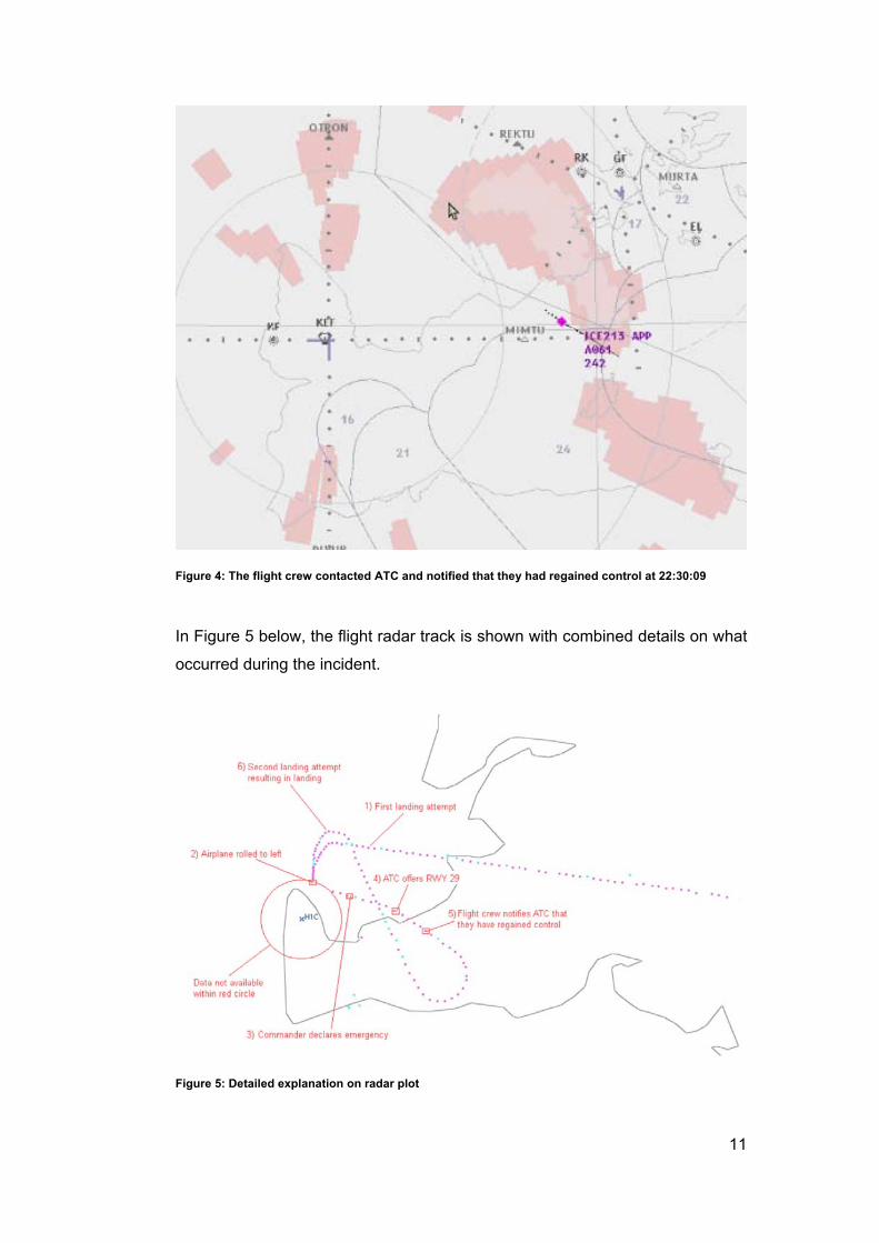
The investigation revealed that the flight crew had regained full control of the
airplane 2 minutes and 42 seconds after the uncommanded left roll, when the
flap overspeed condition was stopped.
Three minutes and 22 seconds after the initial upset, the flight crew contacted
ATC and advised that they had regained control of the airplane. At this time the
airplane was located south of “Straumsvík” as shown in Figure 4.
11
Figure 4: The flight crew contacted ATC and notified that they had regained control at 22:30:09
In Figure 5 below, the flight radar track is shown with combined details on what
occurred during the incident.
Figure 5: Detailed explanation on radar plot
12
The flight crew returned for approach to RWY 20 at Keflavik airport. During the
maneuvering of the airplane back to the final approach position they discussed
the upset and concluded that it had to do with the flight controls and that it
occurred when the flaps were fully deployed. The flight crew therefore decided
to perform the second landing using a long approach and only 15° flap
positioning.
The flight crew requested, and the airline dispatched, a trauma team to meet the
passengers after the landing. The second landing attempt was uneventful and
the airplane landed on RWY 20 at 22:45:33. After the landing, the commander
informed the passengers that during the final approach they’d had problems with
the flight controls of the aircraft and discontinued approach and then returned for
landing.
1.2 Injuries to persons
None.
1.3 Damage to aircraft
None.
1.4 Other damages
None.
13
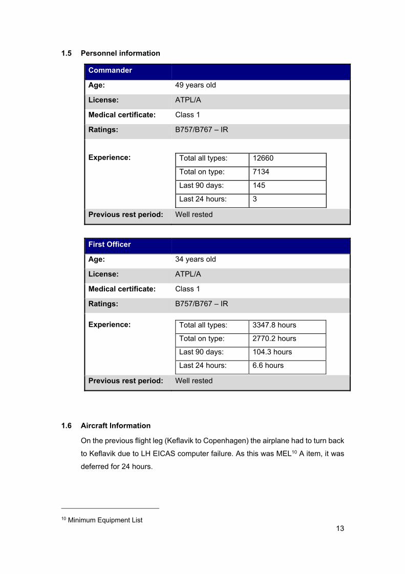
1.5 Personnel information
Commander
Age: 49 years old
License: ATPL/A
Medical certificate: Class 1
Ratings: B757/B767 – IR
Experience:
Total all types: 12660
Total on type: 7134
Last 90 days: 145
Last 24 hours: 3
Previous rest period: Well rested
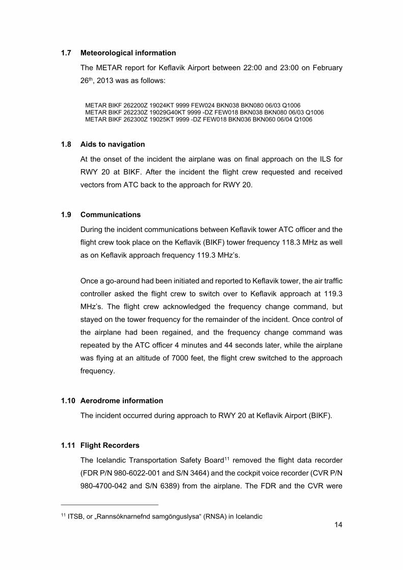
First Officer
Age: 34 years old
License: ATPL/A
Medical certificate: Class 1
Ratings: B757/B767 – IR
Experience:
Total all types: 3347.8 hours
Total on type: 2770.2 hours
Last 90 days: 104.3 hours
Last 24 hours: 6.6 hours
Previous rest period: Well rested
1.6 Aircraft Information
On the previous flight leg (Keflavik to Copenhagen) the airplane had to turn back
to Keflavik due to LH EICAS computer failure. As this was MEL10 A item, it was
deferred for 24 hours.
10 Minimum Equipment List
14
1.7 Meteorological information
The METAR report for Keflavik Airport between 22:00 and 23:00 on February
26th, 2013 was as follows:
METAR BIKF 262200Z 19024KT 9999 FEW024 BKN038 BKN080 06/03 Q1006 METAR BIKF 262230Z 19029G40KT 9999 -DZ FEW018 BKN038 BKN080 06/03 Q1006 METAR BIKF 262300Z 19025KT 9999 -DZ FEW018 BKN036 BKN060 06/04 Q1006
1.8 Aids to navigation
At the onset of the incident the airplane was on final approach on the ILS for
RWY 20 at BIKF. After the incident the flight crew requested and received
vectors from ATC back to the approach for RWY 20.
1.9 Communications
During the incident communications between Keflavik tower ATC officer and the
flight crew took place on the Keflavik (BIKF) tower frequency 118.3 MHz as well
as on Keflavik approach frequency 119.3 MHz’s.
Once a go-around had been initiated and reported to Keflavik tower, the air traffic
controller asked the flight crew to switch over to Keflavik approach at 119.3
MHz’s. The flight crew acknowledged the frequency change command, but
stayed on the tower frequency for the remainder of the incident. Once control of
the airplane had been regained, and the frequency change command was
repeated by the ATC officer 4 minutes and 44 seconds later, while the airplane
was flying at an altitude of 7000 feet, the flight crew switched to the approach
frequency.
1.10 Aerodrome information
The incident occurred during approach to RWY 20 at Keflavik Airport (BIKF).
1.11 Flight Recorders
The Icelandic Transportation Safety Board11 removed the flight data recorder
(FDR P/N 980-6022-001 and S/N 3464) and the cockpit voice recorder (CVR P/N
980-4700-042 and S/N 6389) from the airplane. The FDR and the CVR were
11 ITSB, or „Rannsóknarnefnd samgönguslysa“ (RNSA) in Icelandic
15
transported to the UK Air Accident Investigation Branch, where data was
downloaded and analyzed.
During the analysis of the FDR, it was discovered that spoiler module failure
[SPOILER MODULE0534] had been present during the airplane’s previous 27
flights. It was also confirmed that the right hydraulic system failed at top of
descent, and that the flaps had been deployed to the full position when the
incident occurred.
1.12 Wreckage and Impact information
Not applicable.
1.13 Medical and pathological information
Not applicable.
1.14 Fire
Not applicable.
1.15 Survival aspects
Not applicable.
1.16 Test and research
After the FDR readout, it was known that there had been a spoiler failure present
for the past 27 flights. The Icelandic Transportation Safety Board therefore
requested the operator to inspect and test the spoiler system on the airplane.
The spoiler system on the airplane was subsequently tested, using the following
method:
Removing hydraulic pressure from the spoiler‘s system
Physically, trying to move the spoilers by a “strong” hand
Spoiler #2 did not move
Spoiler #4 was stiff, but did move
Spoiler #6 was loose and moved easily
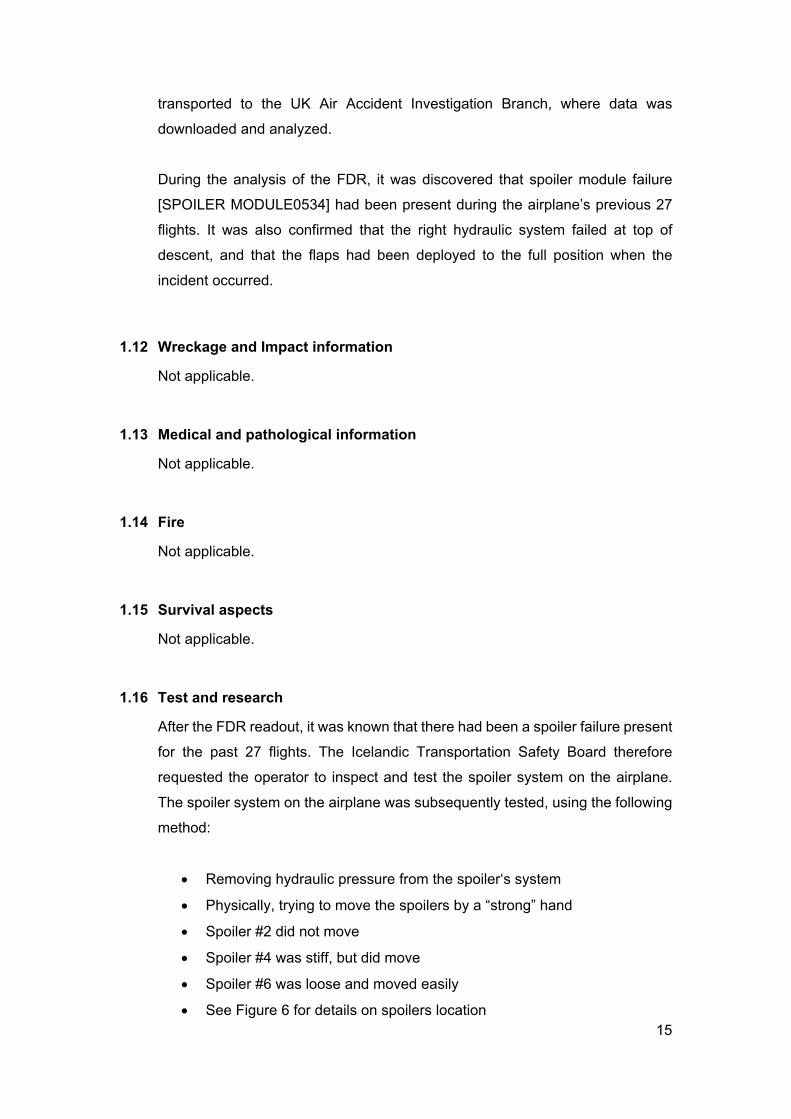
See Figure 6 for details on spoilers location
16
Figure 6: Spoilers on B757-200 airplanes
It was confirmed that spoiler #4 and #6 were not fully locking down as required
during hydraulic system backpressure loss. It was decided to remove all three
spoiler actuators on the left wing that were connected to the right hydraulic
system (# 2, #4 and #6) and to send them for further testing at the component
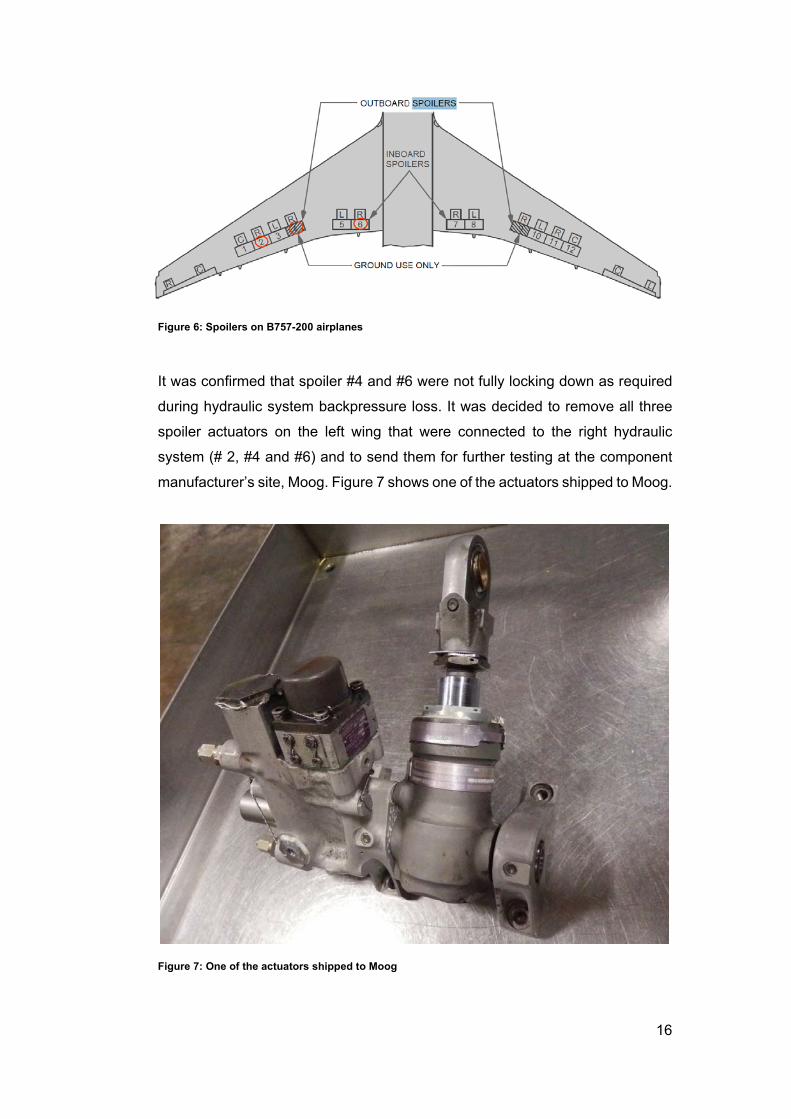
manufacturer’s site, Moog. Figure 7 shows one of the actuators shipped to Moog.
Figure 7: One of the actuators shipped to Moog
17
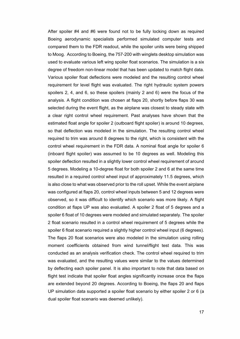
After spoiler #4 and #6 were found not to be fully locking down as required
Boeing aerodynamic specialists performed simulated computer tests and
compared them to the FDR readout, while the spoiler units were being shipped
to Moog. According to Boeing, the 757-200 with winglets desktop simulation was
used to evaluate various left wing spoiler float scenarios. The simulation is a six
degree of freedom non-linear model that has been updated to match flight data.
Various spoiler float deflections were modeled and the resulting control wheel
requirement for level flight was evaluated. The right hydraulic system powers
spoilers 2, 4, and 6, so these spoilers (mainly 2 and 6) were the focus of the
analysis. A flight condition was chosen at flaps 20, shortly before flaps 30 was
selected during the event flight, as the airplane was closest to steady state with
a clear right control wheel requirement. Past analyses have shown that the
estimated float angle for spoiler 2 (outboard flight spoiler) is around 10 degrees,
so that deflection was modeled in the simulation. The resulting control wheel
required to trim was around 8 degrees to the right, which is consistent with the
control wheel requirement in the FDR data. A nominal float angle for spoiler 6
(inboard flight spoiler) was assumed to be 10 degrees as well. Modeling this
spoiler deflection resulted in a slightly lower control wheel requirement of around
5 degrees. Modeling a 10-degree float for both spoiler 2 and 6 at the same time
resulted in a required control wheel input of approximately 11.5 degrees, which
is also close to what was observed prior to the roll upset. While the event airplane
was configured at flaps 20, control wheel inputs between 5 and 12 degrees were
observed, so it was difficult to identify which scenario was more likely. A flight
condition at flaps UP was also evaluated. A spoiler 2 float of 5 degrees and a
spoiler 6 float of 10 degrees were modeled and simulated separately. The spoiler
2 float scenario resulted in a control wheel requirement of 5 degrees while the
spoiler 6 float scenario required a slightly higher control wheel input (6 degrees).
The flaps 20 float scenarios were also modeled in the simulation using rolling
moment coefficients obtained from wind tunnel/flight test data. This was
conducted as an analysis verification check. The control wheel required to trim
was evaluated, and the resulting values were similar to the values determined
by deflecting each spoiler panel. It is also important to note that data based on
flight test indicate that spoiler float angles significantly increase once the flaps
are extended beyond 20 degrees. According to Boeing, the flaps 20 and flaps
UP simulation data supported a spoiler float scenario by either spoiler 2 or 6 (a
dual spoiler float scenario was deemed unlikely).
18
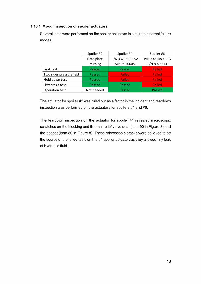
1.16.1 Moog inspection of spoiler actuators
Several tests were performed on the spoiler actuators to simulate different failure
modes.
Spoiler #2 Spoiler #4 Spoiler #6
Data plate P/N 3321500‐09A P/N 3321480‐10A
missing S/N 8950608 S/N 8926513
Leak test Passed Passed Failed
Two sides pressure test Passed Failed Failed
Hold down test Passed Failed Failed
Hysteresis test Passed Passed Failed
Operation test Not needed Passed Passed
The actuator for spoiler #2 was ruled out as a factor in the incident and teardown
inspection was performed on the actuators for spoilers #4 and #6.
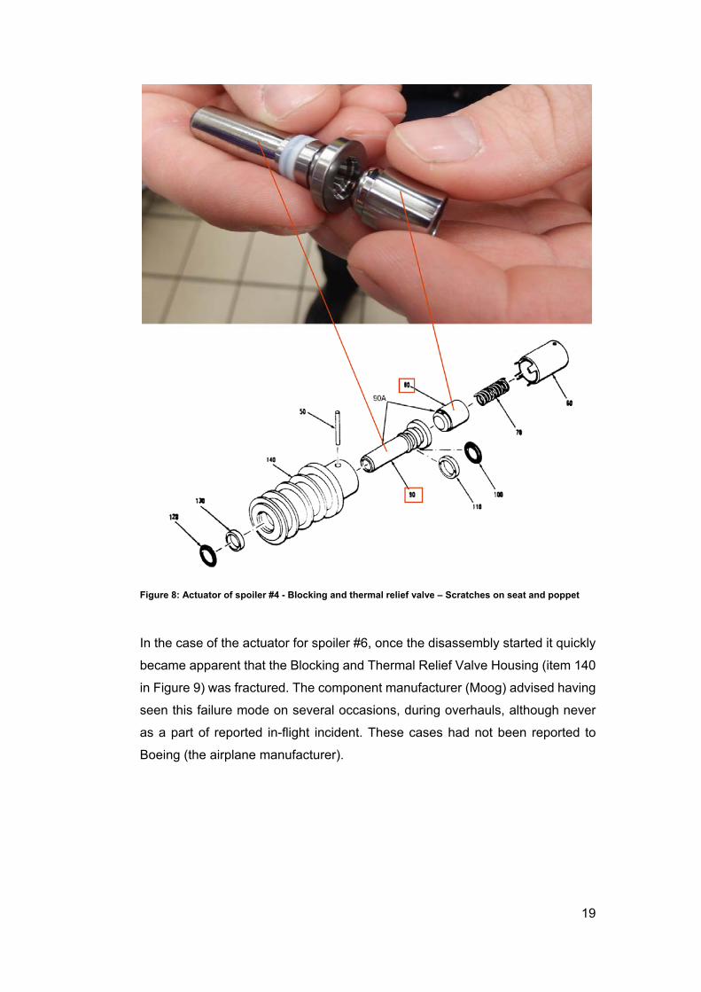
The teardown inspection on the actuator for spoiler #4 revealed microscopic
scratches on the blocking and thermal relief valve seat (item 90 in Figure 8) and
the poppet (item 80 in Figure 8). These microscopic cracks were believed to be
the source of the failed tests on the #4 spoiler actuator, as they allowed tiny leak
of hydraulic fluid.
19
Figure 8: Actuator of spoiler #4 - Blocking and thermal relief valve – Scratches on seat and poppet
In the case of the actuator for spoiler #6, once the disassembly started it quickly
became apparent that the Blocking and Thermal Relief Valve Housing (item 140
in Figure 9) was fractured. The component manufacturer (Moog) advised having
seen this failure mode on several occasions, during overhauls, although never
as a part of reported in-flight incident. These cases had not been reported to
Boeing (the airplane manufacturer).
20
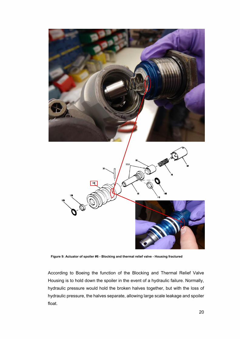
Figure 9: Actuator of spoiler #6 - Blocking and thermal relief valve - Housing fractured
According to Boeing the function of the Blocking and Thermal Relief Valve
Housing is to hold down the spoiler in the event of a hydraulic failure. Normally,
hydraulic pressure would hold the broken halves together, but with the loss of
hydraulic pressure, the halves separate, allowing large scale leakage and spoiler
float.
21
1.17 Organizational and management information
Not applicable.
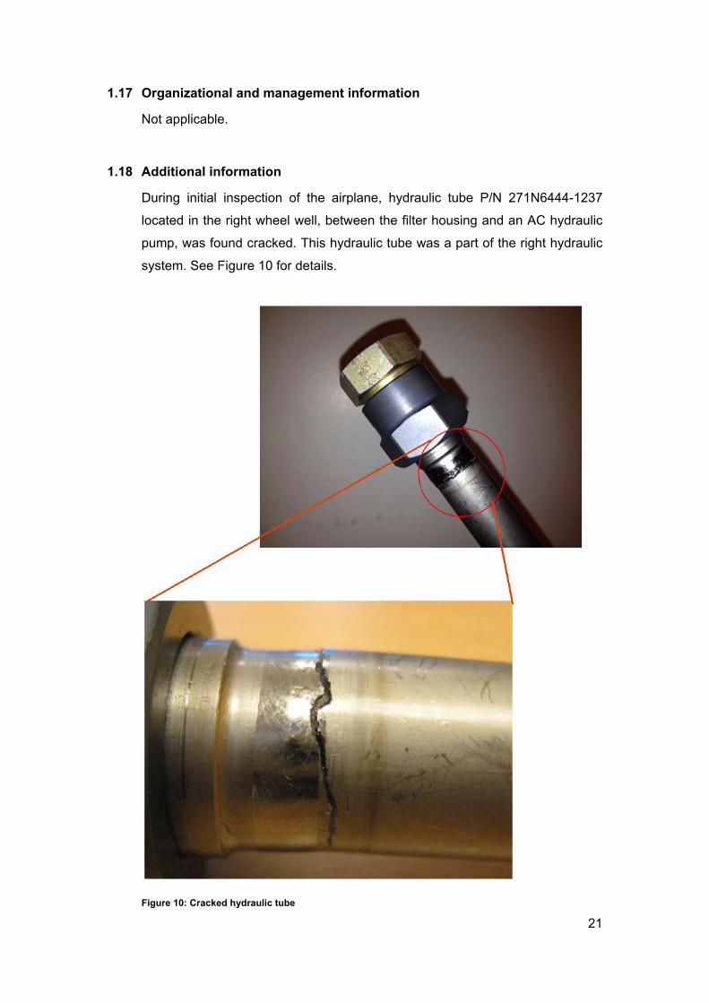
1.18 Additional information
During initial inspection of the airplane, hydraulic tube P/N 271N6444-1237
located in the right wheel well, between the filter housing and an AC hydraulic
pump, was found cracked. This hydraulic tube was a part of the right hydraulic
system. See Figure 10 for details.
Figure 10: Cracked hydraulic tube
22
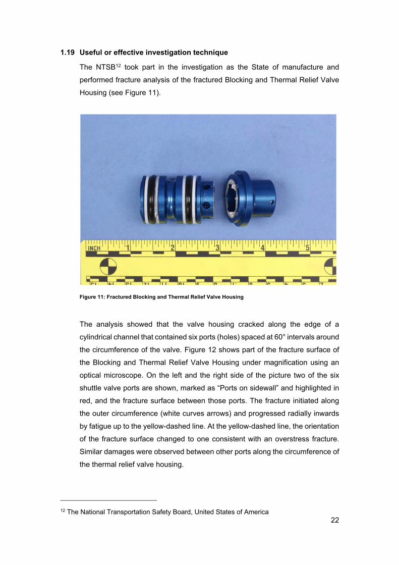
1.19 Useful or effective investigation technique
The NTSB12 took part in the investigation as the State of manufacture and
performed fracture analysis of the fractured Blocking and Thermal Relief Valve
Housing (see Figure 11).
Figure 11: Fractured Blocking and Thermal Relief Valve Housing
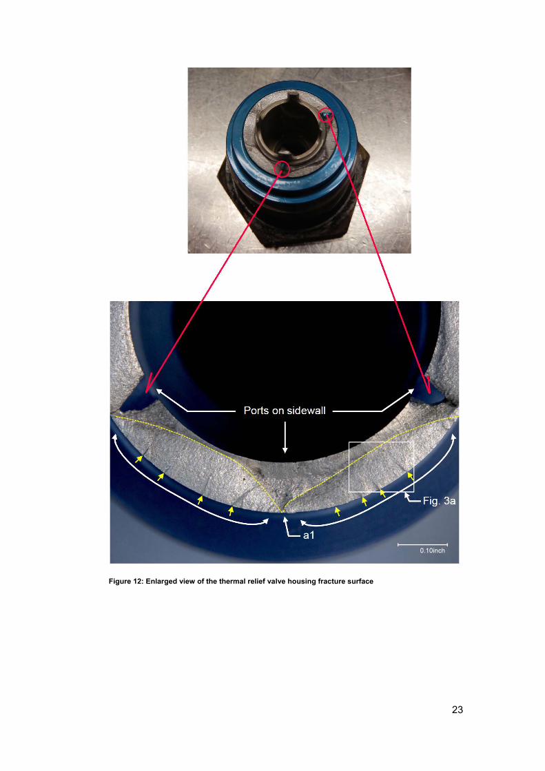
The analysis showed that the valve housing cracked along the edge of a
cylindrical channel that contained six ports (holes) spaced at 60° intervals around
the circumference of the valve. Figure 12 shows part of the fracture surface of
the Blocking and Thermal Relief Valve Housing under magnification using an
optical microscope. On the left and the right side of the picture two of the six
shuttle valve ports are shown, marked as “Ports on sidewall” and highlighted in
red, and the fracture surface between those ports. The fracture initiated along
the outer circumference (white curves arrows) and progressed radially inwards
by fatigue up to the yellow-dashed line. At the yellow-dashed line, the orientation
of the fracture surface changed to one consistent with an overstress fracture.
Similar damages were observed between other ports along the circumference of
the thermal relief valve housing.
12 The National Transportation Safety Board, United States of America
23
Figure 12: Enlarged view of the thermal relief valve housing fracture surface
24
2 Analysis
2.1 Flight operation
During cruise, 34 minutes and 3 seconds prior to the uncommaded left roll, the
right hydraulic system failed as hydraulic tube P/N 271N6444-1237 cracked.
Approximately 3 minutes after this, the autopilot commanded right control wheel
(~ 5 degrees) to maintain wings level. The right control wheel requirement
reduced as the airplane descended and vane angle of attack increased before
returning as the airplane leveled out.
The FDR data show the airplane on descent approaching 10,000 feet pressure
altitude with the center autopilot engaged in Flight Level Change (FLCH) and
Lateral Navigation (LNAV) mode. The airplane was following its target airspeed
and was in the process of descending to a target baro-corrected pressure
altitude, which was selected on the Mode Control Panel (MCP), of just below
2500 feet. The autopilot was commanding a slight right control wheel input to
maintain wings level.
28 minutes and 20 seconds after the right hydraulic system failed, the
speedbrakes were deployed, eventually reaching maximum in-flight detent. At
this speedbrake deflection (spoiler panel deflections not recorded), the control
wheel input returned to around neutral. Computed airspeed decreased as the
crew prepared for flap extension.
28 minutes and 40 seconds after the right hydraulic system failed, there was a
discrete change that indicated the failure of spoiler panel pairs 2/11 and 6/7.
With the speedbrakes remaining deployed, the flaps were extended to 1 degree
30 minutes after the right hydraulic system failed.
30 minutes and 20 seconds after the right hydraulic system failed, a failure
condition was indicated in spoiler panel pair 4/9. As stated earlier, spoiler
deflections are not recorded, but all of the evidence collected at this point
indicated a likely spoiler float scenario on the left wing.
As the airplane continued to descend towards its target altitude, the flaps were
extended to 5 degrees, a left turn was initiated (autopilot roll mode changed to
25
Heading Select [HDG SEL] mode), and the speedbrakes were stowed. Once the
speedbrake handle was stowed, the autopilot returned to commanding a slight
right control wheel input.
32 minutes and 20 seconds after the right hydraulic system failed, just prior to
leveling out at the target altitude, the flaps extended to 15 degrees position.
The airplane leveled off at the target altitude as the autopilot pitch mode
transitioned to Altitude Capture before engaging in Altitude Hold mode. This was
32 minutes and 36 seconds after the right hydraulic system failed.
Approximately 2 seconds later, the autopilot roll mode transitioned to Localizer
mode, and the airplane turned left again to capture the localizer. After rolling out
of the left bank, the airplane required a slightly higher average right control wheel
input to maintain wings level. After the flaps were extended to 20 degrees, the
control wheel requirement increased more to the right.
Glideslope deviation reduced towards zero as the airplane approached the
glideslope beam from below while flying straight and level.
At 22:26, during night, on a 7 NM final approach to RWY 20 at Keflavik Airport,
after the airplane captured the glide slope, the pilot flying called for flaps 30. The
autopilot pitch mode transitioned to Glideslope (G/S) mode just prior to flap
extension to 30 degrees.
As the flaps extended from 20 to 30 degrees, the autopilot increased the right
control wheel input until reaching its maximum control wheel authority (22
degrees). The airplane initially rolled slightly left, but once the autopilot ran out
of control wheel authority, the airplane rolled rapidly to the left. This occurred at
34 minutes and 3 seconds after the right hydraulic system failed. The autopilot
did not disengage.
The pilot flying realized that the airplane was rolling to the left and rapid right
control wheel and rudder pedal inputs were commenced by him 8 seconds after
the uncommanded left roll. This was when the airplane reached an approximate
26
30-degree left bank angle. Multiple right control wheel inputs reached
approximately 80 degrees.
The autopilot and autothrottle concurrently disengaged as the flight crew
commanded the control wheel and rudder pedal inputs.
Following the uncommanded left roll reaching a maximum bank angle of 34°, the
flight crew initiated a go-around, which calls for flaps 20 selection according to
Icelandair procedures. This was done when the airplane was being flown
manually and the go-around altitude had not been set to the required 3000 feet.
The pilot flying increased the engine power, pitched the airplane up and started
retracting the flaps. When the flaps were retracted and go around power had
been applied the airplane started responding to the pilots commands. The flight
crew managed to reduce the bank angle, but did not have the roll under control.
As a result, about 17 seconds after the upset, the flight crew was tackling the
uncommanded roll and initiating a go-around at the same time. At this time, the
left bank angle had decreased to approximately 10 degrees, and the flap handle
was moved to the flaps 20 detent. During this time, the airplane began pitching
up, reaching a maximum of close to 20 degrees before the crew commanded
nose-down column, resulting in a pitch attitude decrease to around 5 degrees
and a normal load factor decrease to 0.3 g’s.
About 27 seconds after the upset, the bank angle increased to approximately 16
degrees to the left before the airplane rapidly rolled to the right around the same
time that the flaps retracted to 20 degrees. The airplane likely rolled to the right
because the flight crew was still maintaining a right control wheel and rudder
input. The airplane reached an approximate 10-degree right bank angle before
the flight crew arrested the roll rate to the right with a left control wheel input.
Around the same time, the autothrottle was re-engaged, and the autopilot Pitch
mode transitioned from G/S mode to Go-Around (G/A) Pitch mode and the
autopilot Roll mode transitioned from Localizer mode to G/A Roll mode, although
the autopilot was not re-engaged.
About 40 seconds after the upset, the airplane overshot its go-around altitude of
3000 feet while the flight crew was still tackling the uncommanded roll.
27
The airplane pitched to approximately 20 degrees before the pitch attitude
decreased to around zero degrees, on average. The autopilot modes continued
to change, transitioning from G/A mode to Altitude Capture (ALT CAP) mode and
eventually Altitude Hold (ALT HOLD) mode while the autopilot Roll mode
transitioned to HDG SEL mode. In this case, with the autopilot not engaged,
these modes were providing Flight Director (FD) guidance.
Flap overspeed occurred at 62 seconds after the upset, as the flaps were
retracting slowly while the airplane speed was increasing rapidly.
The airplane speed continued increasing under flap overspeed condition, while
at the same time the airplane started to descend with a high rate of descent of
up to 3500 feet per minute, for less than 5 seconds, and the pilot flying declaring
that they were descending too rapidly. It was after this escalation of the incident
that the commander declared emergency, one minute and 21 seconds after the
upset.
The first officer was the pilot flying when the incident occurred and the
commander took over as the pilot flying 2 minutes and 21 seconds after the upset
(the uncommanded roll).
The flaps were left in the flap 1 position, leaving the airplane in a flap overspeed
condition for 1 minute and 40 seconds. According to the pilots they were
overloaded with the task at hand and forgot the flaps.
2.2 Operational procedures
When the airplane right hydraulic system failure occurred at top of descent the
flight crew worked the “Hydraulic Quantity” and the “Hydraulic System Pressure
(R only)” checklists in the QRH. The flight crew was therefore well aware prior to
approach, which systems would not be working due to the non-functioning right
hydraulic system.
2.3 Air traffic control
ATC at Keflavik airport, both the tower and the approach, assisted the flight crew:
28
ATCO13 at Keflavik tower set up RWY 29 for short final and offered it to
the flight crew as an alternate after the upset
ATCO at Keflavik tower initiated the airport’s emergency response plan
ATCO at Keflavik approach provided the flight crew with vectors back to
RWY 20, reducing their work load
2.4 Communication
The flight crew stayed on tower frequency despite having received and
acknowledged frequency change instructions. The investigations determined
this to have occurred due to high workload of the flight crew during the incident.
2.5 Aircraft maintenance
The fractured Blocking and Thermal Relief Valve Housing, in spoiler #6 actuator,
was a latent14 failure. It did not raise any flags with maintenance, because with
the right hydraulic system working the hydraulic pressure in the actuator kept the
spoilers from floating.
Once the right hydraulic system became non-functioning, due to the cracked
hydraulic tube, the hydraulic back pressure in the actuator was no longer
present. This, combined with the fractured Blocking and Thermal Relief Valve
Housing, allowed spoiler #6 to float when the flaps were fully extended.
2.6 Aircraft systems
The crack to the hydraulic tube, P/N 271N6444-1237, located in the right wheel
well, caused the loss of the right hydraulic system at top of descent. The crack
is believed to have been caused by weld flaw.
The FDR data shows evidence of a lateral asymmetry consistent with a spoiler
panel 6 float scenario beginning shortly after the right hydraulic system failed in
cruise. Floating spoiler #6 separated the airflow over a section of the left wing,
resulting in a rolling moment to the left.
13 Air Traffic Control Officer 14 Underlying failure not being noticed
29
2.7 Actions already taken as a result of this incident
After the ITSB opened its investigation into this incident, the following actions
have already been performed or initiated:
Icelandair:
Inspected its B757 fleet for this failure type, using the spoiler physical
hand movement inspection method described in chapter 1.16 with the
spoiler’s hydraulic system unpressurized
Replaced three actuators on the incident airplane, as part of the incident
investigation
Inspection of the rest of its 757 fleet resulted in replacement of four
actuators
Reviewed the incident in pilot re-current training
Moog:
Redesigned the Blocking and Thermal Relief Valve Housing with thicker
material section and more radius in the area of the fracture surface. The
redesigned Blocking and Thermal Relief Valve Housing is made from
stainless steel instead of aluminum. This results in better fatigue
performance of the Blocking and Thermal Relief Valve Housing
Boeing:
Issued fleet team bulletin 757-FTS-27-14022 notifying operators of
spoiler float condition in association with a hydraulic system pressure
loss, resulting in an uncommanded roll of an airplane when the flaps
extended between 25° and 30° position
Advised operators that the issue was related to failed spoiler power
control unit (PCU) blocking and thermal relief valve
Released Flight Crew Operation Manual Bulletin TBC-21, regarding the
spoiler float issue and provided flight crews with recommended
procedures to follow in the event of uncommanded roll due to floating
spoiler in the event of a hydraulic pressure loss
Plans to release Boeing Alert Service Bulletin 757-SB-27A0154 on June
25 2016 in coordination with Moog component level service bulletin to
install new improved fatigue life stainless steel blocking and thermal relief
valve into spoiler PCUs
30
3 Conclusion
3.1 Findings
There had been a spoiler module failure present for the past 27 flights before the
incident. This was caused by latent failure in the actuator of spoiler #6, due to a
cracked Blocking and Thermal Relief Valve Housing.
When a hydraulic tube in the right wheel well, part of the right hydraulic system
cracked, it caused a loss of hydraulic pressure in the right hydraulic system at
the top of descent. The crack in the hydraulic tube is believed to have been
caused by weld flaw.
The cracked Blocking and Thermal Relief Valve Housing in the actuator of spoiler
6, combined with the loss of hydraulic pressure in the right hydraulic system,
resulted in floating of spoiler panel 6.
The airplane center autopilot was engaged. It is evident from the data that before
the uncommanded left roll the autopilot was correcting for a lateral asymmetry
that was inducing a left rolling moment. The relatively small amount of autopilot-
commanded control wheel offset went unnoticed by the crew, which had the
effect of masking the lateral asymmetry until saturation occurred.
The control wheel requirement to maintain wings level increased as the flaps
extended. Initially the autopilot was able to sufficiently control the rolling moment
due to the floating spoiler panel. Once the flaps were extended to 30 degrees,
the autopilot control wheel authority was saturated at 22 degrees, and the
autopilot could no longer counter the rolling moment due to the floating spoiler.
This resulted in an uncommanded roll to the left. The autopilot did not disengage.
Following the uncommanded left roll reaching a maximum bank angle of 34°, the
flight crew initiated a go-around, which calls for flaps 20 selection according to
Icelandair procedures.
Following the uncommanded roll, while the pilots were trying to regain control of
the airplane, flap overspeed occurred. Then the airplane was pitched down. This
resulted in a high rate of descent of up to 3500 feet per minute, which lasted for
31
less than 5 seconds. The pilot flying stated that they were descending too rapidly
and the commander declared an emergency.
The commander took over as the pilot flying 2 minutes and 21 seconds after the
upset (the uncommanded roll).
The investigation revealed that the flight crew had regained full control of the
airplane 2 minutes and 42 seconds after the uncommanded left roll, when the
flap overspeed condition was stopped.
The uncommanded roll was due to a rolling moment induced by a floating spoiler
panel that could not be countered by the autopilot’s control wheel authority
following the selection of flaps 30.
32
3.2 Causes
Latent failure in the actuator of spoiler #6, due to a cracked Blocking and
Thermal Relief Valve Housing
Loss of right hydraulic system pressure due to cracked hydraulic tube
Full deployment of the flaps, with the right hydraulic system unpressurized and
the Blocking and Thermal Relief Valve Housing cracked, caused spoiler #6 to
float
Floating spoiler #6 separating the airflow over a section of the left wing, causing
the airplane to roll to the left due to unbalance in lift between the left and the
right wings
33
4 Safety Recommendations
Moog:
In co-operation with the airplane’s manufacturer, set up a program to support
fleet wide replacement of the blocking and thermal relief valve housing with the
fatigue improved unit made from stainless steel
Boeing:
Issue the planned service bulletin 757-SB57A0154 to support fleet wide
replacement of the Blocking and Thermal Relief Valve Housing in co-operation
with the actuator‘s manufacturer
Research other Boeing large transport category aircraft for similar spoiler
actuator design and take corrective action as needed
FAA:
Research the need for making inspections, and possible replacement, of
spoiler actuator’s Blocking and Thermal Relief Valve Housing mandatory via
issue of airworthiness directive, for Boeing 757 airplanes
Research the need for making inspections, and possible replacement, of
spoiler actuator’s Blocking and Thermal Relief Valve Housing mandatory via
issue of airworthiness directive, for other large transport category aircraft with
similar spoiler actuator design
The following board members approved the report:
Bryndís Lára Torfadóttir, board member
Gestur Gunnarsson, board member
Hörður Arilíusson, deputy board member
Reykjavik, 13. August 2015
On behalf of the Icelandic Transportation Safety Board
Ragnar Guðmundsson, Investigator-In-Charge